EP3839206A1 - Vane motor - Google Patents
Vane motor Download PDFInfo
- Publication number
- EP3839206A1 EP3839206A1 EP20020102.8A EP20020102A EP3839206A1 EP 3839206 A1 EP3839206 A1 EP 3839206A1 EP 20020102 A EP20020102 A EP 20020102A EP 3839206 A1 EP3839206 A1 EP 3839206A1
- Authority
- EP
- European Patent Office
- Prior art keywords
- casing
- rotor
- inner liner
- rotational
- fluid
- Prior art date
- Legal status (The legal status is an assumption and is not a legal conclusion. Google has not performed a legal analysis and makes no representation as to the accuracy of the status listed.)
- Granted
Links
Images


Classifications
-
- F—MECHANICAL ENGINEERING; LIGHTING; HEATING; WEAPONS; BLASTING
- F01—MACHINES OR ENGINES IN GENERAL; ENGINE PLANTS IN GENERAL; STEAM ENGINES
- F01C—ROTARY-PISTON OR OSCILLATING-PISTON MACHINES OR ENGINES
- F01C1/00—Rotary-piston machines or engines
- F01C1/30—Rotary-piston machines or engines having the characteristics covered by two or more groups F01C1/02, F01C1/08, F01C1/22, F01C1/24 or having the characteristics covered by one of these groups together with some other type of movement between co-operating members
- F01C1/34—Rotary-piston machines or engines having the characteristics covered by two or more groups F01C1/02, F01C1/08, F01C1/22, F01C1/24 or having the characteristics covered by one of these groups together with some other type of movement between co-operating members having the movement defined in group F01C1/08 or F01C1/22 and relative reciprocation between the co-operating members
- F01C1/344—Rotary-piston machines or engines having the characteristics covered by two or more groups F01C1/02, F01C1/08, F01C1/22, F01C1/24 or having the characteristics covered by one of these groups together with some other type of movement between co-operating members having the movement defined in group F01C1/08 or F01C1/22 and relative reciprocation between the co-operating members with vanes reciprocating with respect to the inner member
-
- F—MECHANICAL ENGINEERING; LIGHTING; HEATING; WEAPONS; BLASTING
- F01—MACHINES OR ENGINES IN GENERAL; ENGINE PLANTS IN GENERAL; STEAM ENGINES
- F01C—ROTARY-PISTON OR OSCILLATING-PISTON MACHINES OR ENGINES
- F01C1/00—Rotary-piston machines or engines
- F01C1/30—Rotary-piston machines or engines having the characteristics covered by two or more groups F01C1/02, F01C1/08, F01C1/22, F01C1/24 or having the characteristics covered by one of these groups together with some other type of movement between co-operating members
- F01C1/34—Rotary-piston machines or engines having the characteristics covered by two or more groups F01C1/02, F01C1/08, F01C1/22, F01C1/24 or having the characteristics covered by one of these groups together with some other type of movement between co-operating members having the movement defined in group F01C1/08 or F01C1/22 and relative reciprocation between the co-operating members
- F01C1/344—Rotary-piston machines or engines having the characteristics covered by two or more groups F01C1/02, F01C1/08, F01C1/22, F01C1/24 or having the characteristics covered by one of these groups together with some other type of movement between co-operating members having the movement defined in group F01C1/08 or F01C1/22 and relative reciprocation between the co-operating members with vanes reciprocating with respect to the inner member
- F01C1/348—Rotary-piston machines or engines having the characteristics covered by two or more groups F01C1/02, F01C1/08, F01C1/22, F01C1/24 or having the characteristics covered by one of these groups together with some other type of movement between co-operating members having the movement defined in group F01C1/08 or F01C1/22 and relative reciprocation between the co-operating members with vanes reciprocating with respect to the inner member the vanes positively engaging, with circumferential play, an outer rotatable member
-
- F—MECHANICAL ENGINEERING; LIGHTING; HEATING; WEAPONS; BLASTING
- F01—MACHINES OR ENGINES IN GENERAL; ENGINE PLANTS IN GENERAL; STEAM ENGINES
- F01C—ROTARY-PISTON OR OSCILLATING-PISTON MACHINES OR ENGINES
- F01C21/00—Component parts, details or accessories not provided for in groups F01C1/00 - F01C20/00
- F01C21/02—Arrangements of bearings
-
- F—MECHANICAL ENGINEERING; LIGHTING; HEATING; WEAPONS; BLASTING
- F01—MACHINES OR ENGINES IN GENERAL; ENGINE PLANTS IN GENERAL; STEAM ENGINES
- F01C—ROTARY-PISTON OR OSCILLATING-PISTON MACHINES OR ENGINES
- F01C21/00—Component parts, details or accessories not provided for in groups F01C1/00 - F01C20/00
- F01C21/08—Rotary pistons
- F01C21/0809—Construction of vanes or vane holders
-
- F—MECHANICAL ENGINEERING; LIGHTING; HEATING; WEAPONS; BLASTING
- F01—MACHINES OR ENGINES IN GENERAL; ENGINE PLANTS IN GENERAL; STEAM ENGINES
- F01C—ROTARY-PISTON OR OSCILLATING-PISTON MACHINES OR ENGINES
- F01C21/00—Component parts, details or accessories not provided for in groups F01C1/00 - F01C20/00
- F01C21/10—Outer members for co-operation with rotary pistons; Casings
-
- F—MECHANICAL ENGINEERING; LIGHTING; HEATING; WEAPONS; BLASTING
- F01—MACHINES OR ENGINES IN GENERAL; ENGINE PLANTS IN GENERAL; STEAM ENGINES
- F01C—ROTARY-PISTON OR OSCILLATING-PISTON MACHINES OR ENGINES
- F01C21/00—Component parts, details or accessories not provided for in groups F01C1/00 - F01C20/00
- F01C21/18—Arrangements for admission or discharge of the working fluid, e.g. constructional features of the inlet or outlet
-
- F—MECHANICAL ENGINEERING; LIGHTING; HEATING; WEAPONS; BLASTING
- F04—POSITIVE - DISPLACEMENT MACHINES FOR LIQUIDS; PUMPS FOR LIQUIDS OR ELASTIC FLUIDS
- F04C—ROTARY-PISTON, OR OSCILLATING-PISTON, POSITIVE-DISPLACEMENT MACHINES FOR LIQUIDS; ROTARY-PISTON, OR OSCILLATING-PISTON, POSITIVE-DISPLACEMENT PUMPS
- F04C18/00—Rotary-piston pumps specially adapted for elastic fluids
- F04C18/30—Rotary-piston pumps specially adapted for elastic fluids having the characteristics covered by two or more of groups F04C18/02, F04C18/08, F04C18/22, F04C18/24, F04C18/48, or having the characteristics covered by one of these groups together with some other type of movement between co-operating members
- F04C18/34—Rotary-piston pumps specially adapted for elastic fluids having the characteristics covered by two or more of groups F04C18/02, F04C18/08, F04C18/22, F04C18/24, F04C18/48, or having the characteristics covered by one of these groups together with some other type of movement between co-operating members having the movement defined in group F04C18/08 or F04C18/22 and relative reciprocation between the co-operating members
- F04C18/344—Rotary-piston pumps specially adapted for elastic fluids having the characteristics covered by two or more of groups F04C18/02, F04C18/08, F04C18/22, F04C18/24, F04C18/48, or having the characteristics covered by one of these groups together with some other type of movement between co-operating members having the movement defined in group F04C18/08 or F04C18/22 and relative reciprocation between the co-operating members with vanes reciprocating with respect to the inner member
- F04C18/348—Rotary-piston pumps specially adapted for elastic fluids having the characteristics covered by two or more of groups F04C18/02, F04C18/08, F04C18/22, F04C18/24, F04C18/48, or having the characteristics covered by one of these groups together with some other type of movement between co-operating members having the movement defined in group F04C18/08 or F04C18/22 and relative reciprocation between the co-operating members with vanes reciprocating with respect to the inner member the vanes positively engaging, with circumferential play, an outer rotatable member
-
- F—MECHANICAL ENGINEERING; LIGHTING; HEATING; WEAPONS; BLASTING
- F04—POSITIVE - DISPLACEMENT MACHINES FOR LIQUIDS; PUMPS FOR LIQUIDS OR ELASTIC FLUIDS
- F04C—ROTARY-PISTON, OR OSCILLATING-PISTON, POSITIVE-DISPLACEMENT MACHINES FOR LIQUIDS; ROTARY-PISTON, OR OSCILLATING-PISTON, POSITIVE-DISPLACEMENT PUMPS
- F04C2/00—Rotary-piston machines or pumps
- F04C2/30—Rotary-piston machines or pumps having the characteristics covered by two or more groups F04C2/02, F04C2/08, F04C2/22, F04C2/24 or having the characteristics covered by one of these groups together with some other type of movement between co-operating members
- F04C2/34—Rotary-piston machines or pumps having the characteristics covered by two or more groups F04C2/02, F04C2/08, F04C2/22, F04C2/24 or having the characteristics covered by one of these groups together with some other type of movement between co-operating members having the movement defined in groups F04C2/08 or F04C2/22 and relative reciprocation between the co-operating members
- F04C2/344—Rotary-piston machines or pumps having the characteristics covered by two or more groups F04C2/02, F04C2/08, F04C2/22, F04C2/24 or having the characteristics covered by one of these groups together with some other type of movement between co-operating members having the movement defined in groups F04C2/08 or F04C2/22 and relative reciprocation between the co-operating members with vanes reciprocating with respect to the inner member
- F04C2/348—Rotary-piston machines or pumps having the characteristics covered by two or more groups F04C2/02, F04C2/08, F04C2/22, F04C2/24 or having the characteristics covered by one of these groups together with some other type of movement between co-operating members having the movement defined in groups F04C2/08 or F04C2/22 and relative reciprocation between the co-operating members with vanes reciprocating with respect to the inner member the vanes positively engaging, with circumferential play, an outer rotatable member
Definitions
- the present invention relates to a vane motor that can generate a rotational force by a hydraulic force to improve output efficiency.
- a vane motor is a mechanical actuator that converts hydraulic pressure into rotation power.
- FIG. 1 shows one example of a vane motor according to the related art.
- a rotor is rotatably installed in a casing 211.
- the casing 211 is provided with a fluid inlet 253 through which a fluid for generating pressure flows in, and a fluid outlet through which the fluid flows out. If the pressurized fluid flows in through the fluid inlet, the pressurized fluid acts on vanes 235 each of which spreads toward the outside of the rotor, and has a variable length. Accordingly, the vanes 235 are moving to the pressurized direction, the rotor turns within the casing 211. If the pressurized fluid for applying the pressure to the vanes 235 arrives at the fluid outlet 255 of the casing, the fluid is discharged through the fluid outlet 255 which is a low pressure side.
- the pressurized fluid flowing in through the fluid inlet arrives at the fluid outlet which is the low pressure side, the fluid is discharged through the fluid outlet, and thus the pressurized fluid applies the pressure to the vanes in the path to turn the rotor.
- the vanes 235 are engaged to a rotor body 231, and the length of the respective vanes protruding from the rotor body 231 is variable.
- the vanes 235 are inserted in grooves 231a formed on an outer peripheral surface of the rotor body 231, and are able to move in a longitudinal direction of the groove.
- the vane 235 moves out from the groove 231a of the rotor body 231 at the wide gap to increase a protruding length of the vane 235, while the vane 235 moves in the groove of the rotor body at the narrow gap to decrease the protruding length of vane.
- a resilient member such as a spring, may be provided between a bottom portion of the rotor groove 231 and the vane 235 so that the vane can smoothly move in or out from the groove of the rotor body 231. Otherwise, since the vane can slide out from the groove by a centrifugal force of the rotor, a separate spring may not be provided.
- the vane motor of the related art has problems in that if the gap between the distal end of the vane 235 and the inner wall surface of the casing 211 is too wide, the fluid leaks through the gap to lead to a loss of pressure, and in that if the gap is too narrow, friction between the vane and the inner wall surface of the casing is increased, so that a lot of energy generated by the pressurized fluid is significantly lost, and thus maintenance costs are increased due to abrasion of the vanes and the inner wall surface.
- These problems are in a trade-off relation and cannot be completely solved in the vane motor of the prior art. Therefore, for vane motors of various materials and sizes, a proper size of the gap should be acquired on an experimental basis to increase the efficiency and the durability of each vane motor.
- the total amount of the force of the fluid acting on the vane should be increased. Since the total amount of the force is equal to the result obtained by multiplying the pressure, which is a force acting on a unit area, by an area of the inner wall surface, to which the pressure is applied, it is necessary to increase the area of the inner wall surface, with which the fluid and the vanes come into contact.
- the vane motor should be designed to increase the contact area with the fluid within a limit to keep the connection between the vanes and the rotor in stable.
- the invention has been made in view of the above problems included in a vane motor of the related art, and one object of the invention is to provide a vane motor having configuration capable of improving efficiency.
- a vane motor including: a casing including an inlet port and an outlet port, through which a pressurized fluid comes in or out; a rotor being installed in the casing, turning around a rotational shaft by the pressurized fluid, the rotor including a rotor body which has a substantially cylindrical shape and an axis coinciding with an axis of the rotational shaft and a plurality of vanes which is installed in grooves formed on an outer circumferential surface of the rotor body and has a portion protruding from the groove and (the portion) having a length varied in accordance with a rotational phase, and an inner liner of a cylindrical shape which is installed in the casing and receives the rotor therein, in which a distal end of the vane comes into contact with an inner wall surface of the inner liner while the pressurized fluid is retained therein until the pressurized fluid flowing through the inlet port of the casing is discharged from the outlet port of the cas
- the imaginary rotational axis of the inner liner and the rotational shaft of the rotor can be maintained at constant positions.
- the vane motor includes a rolling member which, when the inner liner is rotated in the casing, is interposed between an outer surface of the inner liner and the inner wall surface of the casing to reduce friction therebetween
- the casing is configured in such a way that both ends of an outer liner of a cylindrical shape larger than the inner liner are closed by disc-shaped finish plates.
- At least one of the finish plates is configured in such a way that the rotational shaft pass through and is exposed out of the finish plate to transmit the rotational force, and a bearing is mounted between the rotational shaft and the finish plate.
- the vanes there is a fine gap between the finish plates and other components like the inner liner, the vanes in axial (longitudinal) direction, so that the components are able to slide with the finish plates, but the pressurized fluid is hardly leaked through the gap.
- At least one of the finish plates may be provided with a fluid inlet and a fluid outlet.
- the fluid inlet and the fluid outlet are formed in such a way that at least a portion of the fluid inlet and at least a portion of the fluid outlet is overlapped with a gap or space between the inner liner and the rotor body, when seen in an axial direction, and the fluid inlet and the fluid outlet are extended in an arc shape in a circumferential direction.
- the inlet port and the outlet port may be located in the gap or space between an inner liner of a cylindrical shape and the rotor body, when seen from a cross-sectional view of the rotational shaft, and preferably, in both edges of the opening of the groove formed on the rotor body to receive the vane, enlarged portion through which a rear surface of the vane is more exposed may be formed at the rear side edge portion.
- the enlarged portion may be provided on both ends thereof in the longitudinal direction.
- the enlarged portion may be formed at the portion in which the start portion of the arch-shaped fluid inlet is overlapped.
- the invention changes the structure of the vane motor of the prior art in which when the rotor turns, the distal ends of the vanes contact against the inner wall surface of the casing, so that the inner wall surface of the casing and the vanes are worn out, to increase a frequency of replacement and repair. Since the energy consumed by the abrasion is decreased and is used to generate the rotational force, the energy converting efficiency of the vane motor is improved.
- the vane motor 1 of this embodiment includes a casing forming an exterior, an inner liner 20 of a cylindrical shape, and a rotor positioned in the inner liner 20.
- the casing includes a casing body 11 formed of a substantially cylindrical shape, and finish plates 13 and 15 for finishing both ends of the casing body 11 in a longitudinal direction.
- the finish plates 13 and 15 are respectively provided with rotational shaft mounting holes 131 and 151, through which a rotational shaft 33 connected to the rotor passes, arc-shaped fluid inlets 135 and 155, through which a pressurized fluid comes in from the outside, and arc-shaped fluid outlets 133 and 153, through which the pressurized fluid comes out.
- a bearing 17 is installed in the rotational shaft mounting holes 131 and 151, so that the rotational shaft 33 does not come into direct contact with the finish plates 13 and 15, thereby reducing friction between the rotational shaft 33 and the finish plates 13 and 15.
- the inner liner 20 is installed in the casing.
- the length of the inner liner 20 is substantially identical to that of the casing body 11, and both ends of the inner liner 20 contact against the inner surfaces of the finish plates 13 and 15 of the casing in a longitudinal direction, with a fine gap between both ends and the inner surfaces.
- the inner liner 20 turns in the casing, the inner liner produces sliding friction between the inner surfaces of the finish plates 13 and 15 and the inner liner.
- the inner liner 20 is laid on a plurality of rolling members 19 which are disposed on a concave portion 119 formed on the inner wall of the casing wall 11, when the inner liner 20 is installed in the casing.
- the rolling member has a roller 19a and a rolling shaft 19b, and the rolling shaft 19b is formed in the shape of a cylinder or a rotational shaft, and is rotatably installed in parallel with the rotational shaft 33. If the inner liner 20 turns in the casing body 11, the rolling shaft coming into contact with the outer surface of the inner liner rotates, and thus there is no sliding friction between the turning inner liner 20 and the inner surface of the casing body 11.
- the rotor is installed in the inner liner 20, and includes a cylindrical rotor body 31 having the rotational shaft 33, and a plurality of vanes 35 engaged with each groove 31a of the rotor body 31.
- the length of the cylinder forming the rotor body 31 is substantially identical to that of the casing body 11, and when the rotor turns, both ends of the cylinder come into contact with the inner surfaces of the finish plates 13 and 15 in the state in which a fine gap is therebetween, thereby producing sliding friction between the inner surfaces of the finish plates 13 and 15 and both ends thereof.
- the connecting manner between the rotor body 31 and the vane 35 may be substantially identical to that of the vane motor of the prior art. Since the operation of the vane 35 in the groove 31a is widely known in the art, the detailed description will be omitted herein.
- This embodiment is substantially identical to the first embodiment, except that the rotor is not installed to come into directly contact with the inner surface of the casing body 11, but is installed to come into directly contact with the inner surface of the inner liner 20.
- the rotational shaft 33 of the rotor is parallel with an imaginary rotational axis of the inner liner 20, but is spaced apart from the rotational axis of the inner liner at a distance.
- the finish plates 13 and 15 of the casing are respectively provided with a hole through which the rotational shaft 33 penetrates. The position of the hole is spaced apart from the rotational axis of the cylinder forming the casing at a distance.
- the rotor disposed in the casing body 11 pushes the inner liner 20 of the cylindrical shape against the rolling member 19 of the casing body 11, so that an imaginary rotational axis of the cylinder forming the casing body is spaced apart from the imaginary rotational axis of the inner liner 20 of the cylindrical shape at an interval.
- the distance between the rotor body 31 and the inner wall surface of the inner liner 20 is minimized at the position where the rotor pushes the inner liner 20, and thus the vane 35 is completely inserted in the groove 31a so that the rotor body 31 contacts against the inner liner 20, or a protruding length of the vane 35 from the rotor body 31 is decreased.
- the distance between the rotor body 31 and the inner surface of the inner liner 20 is maximized, thereby increasing the protruding length of the vane 35 from the rotor body 31.
- the groove 31a may be formed in various shapes, if necessary, and the vane 35 slidably moving in or out along the groove 31a may be provided in a direction perpendicular to a vertical plane of the cylindrical rotor body 31, but protrudes at a desired angle with respect to the vertical plane.
- the groove is formed on an outer peripheral surface of the rotor body 31 along the entire length thereof in the longitudinal direction, and is slightly sloped at a desired angle with respect to a radial direction pointing along a radius from the rotational shaft 33 toward the rotational direction of the rotor. Therefore, the vane protrudes at a desired angle toward the rotational direction with respect to the vertical plane of the rotor body.
- a supplier for supplying the pressurized fluid to the fluid inlets 135 and 155 of the vane motor from the outside and a collector for receiving the pressurized fluid from the fluid outlets 133 and 153 may be connected to the vane motor of this embodiment, similar to the first embodiment, but the rotor body 31 and the vanes 35 of the rotor are not operated in the casing body 11, but is operated in the inner liner 20.
- the fluid inlet of the vane motor is connected with the supplier (not illustrated) for supplying the pressurized fluid from the outside. Since both of the finish plates 13 and 15 installed to both sides of the vane motor are provided with the fluid inlets 135 and 155 and the fluid outlets 133 and 153, the supplier is branched at any point to supply the pressurized fluid to both fluid inlets of the finish plates 13 and 15. Similarly, the collector is branched at any point to receive the pressurized fluid from both fluid outlets of the finish plates 13 and 15, of which the pressure of the fluid used in the vane motor is decreased.
- the pressurized fluid passing through the arc-shaped fluid inlets of the finish plate flows in the space between the rotor body and the inner wall surface of the inner liner at that position.
- the pressurized fluid applies the pressure to the vane forming a portion of an interface of the space. If the pressure applied to the rear surface of the vane is higher than that applied to the front surface, the vane moves forward. Since the rotor provided with the vanes is rotatably fixed by the rotational shaft, the rotor does not move in parallel, but is just rotated.
- the space between the rotor and the inner wall surface of the inner liner 20 is gradually increased from the positions of the fluid inlets 135 and 155, and the vane 35 protrudes at the most from the groove 31a, so that the pressure applied to the vane is gradually increased. Since the arc-shaped fluid outlets 133 and 153 start to appear next to the position of the maximum gap, the pressurized fluid comes out through the fluid outlets, so that the pressure of the fluid is decreased.
- the rotor of this embodiment is rotated by the pressure difference, similar to the rotor of the vane motor according to the prior art, but the inner liner 20 of the cylindrical shape forms the space in which the pressurized fluid operates, instead of the casing. Since the inner liner is not stationary, the rotational force is transferred to the inner liner 20 of the cylindrical shape which comes into contact with the distal end of the vane 35, due to the friction, when the rotor turns. The inner liner 20 is rotated at the nearly equal linear velocity at the position of the distal end of the respective vanes which forms the outermost circumference of the rotor.
- the inner liner is rotated in the casing, and the rolling members 19, such as a rolling shaft, are interposed between the inner liner and the casing to reduce the sliding friction between the inner liner and the casing body 11.
Landscapes
- Engineering & Computer Science (AREA)
- Mechanical Engineering (AREA)
- General Engineering & Computer Science (AREA)
- Hydraulic Motors (AREA)
- Rotary Pumps (AREA)
Abstract
Description
- The present invention relates to a vane motor that can generate a rotational force by a hydraulic force to improve output efficiency.
- A vane motor is a mechanical actuator that converts hydraulic pressure into rotation power.
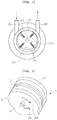
FIG. 1 shows one example of a vane motor according to the related art. - Referring to
FIG. 1 , a rotor is rotatably installed in acasing 211. Thecasing 211 is provided with afluid inlet 253 through which a fluid for generating pressure flows in, and a fluid outlet through which the fluid flows out. If the pressurized fluid flows in through the fluid inlet, the pressurized fluid acts onvanes 235 each of which spreads toward the outside of the rotor, and has a variable length. Accordingly, thevanes 235 are moving to the pressurized direction, the rotor turns within thecasing 211. If the pressurized fluid for applying the pressure to thevanes 235 arrives at thefluid outlet 255 of the casing, the fluid is discharged through thefluid outlet 255 which is a low pressure side. - Specifically, if the pressurized fluid flowing in through the fluid inlet arrives at the fluid outlet which is the low pressure side, the fluid is discharged through the fluid outlet, and thus the pressurized fluid applies the pressure to the vanes in the path to turn the rotor.
- The
vanes 235 are engaged to arotor body 231, and the length of the respective vanes protruding from therotor body 231 is variable. For the variable feature, thevanes 235 are inserted ingrooves 231a formed on an outer peripheral surface of therotor body 231, and are able to move in a longitudinal direction of the groove. Since a gap between the inner wall surface of thecasing 211 and arotational shaft 233 of therotor body 231 is varied according to a position of the inner wall surface of the casing, thevane 235 moves out from thegroove 231a of therotor body 231 at the wide gap to increase a protruding length of thevane 235, while thevane 235 moves in the groove of the rotor body at the narrow gap to decrease the protruding length of vane. - A resilient member, such as a spring, may be provided between a bottom portion of the
rotor groove 231 and thevane 235 so that the vane can smoothly move in or out from the groove of therotor body 231. Otherwise, since the vane can slide out from the groove by a centrifugal force of the rotor, a separate spring may not be provided. - At the narrow gap in which the gap between the
rotor body 231 and the inner wall surface of the casing becomes narrow, when therotor body 231 turns, a distal end of thevane 235 is pressurized so that the vane moves in thegroove 231a while contacting against the inner wall surface. - However, the vane motor of the related art has problems in that if the gap between the distal end of the
vane 235 and the inner wall surface of thecasing 211 is too wide, the fluid leaks through the gap to lead to a loss of pressure, and in that if the gap is too narrow, friction between the vane and the inner wall surface of the casing is increased, so that a lot of energy generated by the pressurized fluid is significantly lost, and thus maintenance costs are increased due to abrasion of the vanes and the inner wall surface. These problems are in a trade-off relation and cannot be completely solved in the vane motor of the prior art. Therefore, for vane motors of various materials and sizes, a proper size of the gap should be acquired on an experimental basis to increase the efficiency and the durability of each vane motor. - In order to increase the rotational force of the rotor by use of the pressurized fluid, the total amount of the force of the fluid acting on the vane should be increased. Since the total amount of the force is equal to the result obtained by multiplying the pressure, which is a force acting on a unit area, by an area of the inner wall surface, to which the pressure is applied, it is necessary to increase the area of the inner wall surface, with which the fluid and the vanes come into contact.
- However, if the vane moves out too far from the groove, the vane may be completely released from the groove, or the vane may be vibrated or be in an unstable state while producing the friction between the vane and the inner wall surface of the casing. Therefore, the vane motor should be designed to increase the contact area with the fluid within a limit to keep the connection between the vanes and the rotor in stable.
-
- Patent Document 1: Korean Patent No.:
10-1116511 - Patent Document 2: Korean Patent No.:
10-1874583 - Therefore, the invention has been made in view of the above problems included in a vane motor of the related art, and one object of the invention is to provide a vane motor having configuration capable of improving efficiency.
- According to one aspect of the present invention,
there is provided a vane motor including: a casing including an inlet port and an outlet port, through which a pressurized fluid comes in or out;
a rotor being installed in the casing, turning around a rotational shaft by the pressurized fluid,
the rotor including a rotor body which has a substantially cylindrical shape and an axis coinciding with an axis of the rotational shaft and a plurality of vanes which is installed in grooves formed on an outer circumferential surface of the rotor body and has a portion protruding from the groove and (the portion) having a length varied in accordance with a rotational phase, and
an inner liner of a cylindrical shape which is installed in the casing and receives the rotor therein, in which a distal end of the vane comes into contact with an inner wall surface of the inner liner while the pressurized fluid is retained therein until the pressurized fluid flowing through the inlet port of the casing is discharged from the outlet port of the casing, and an imaginary rotational axis of the inner liner is spaced apart from a rotational axis of the rotational shaft in a parallel state, but is able to rotate together with the rotor when the rotor turns. - The imaginary rotational axis of the inner liner and the rotational shaft of the rotor can be maintained at constant positions. The vane motor includes a rolling member which, when the inner liner is rotated in the casing, is interposed between an outer surface of the inner liner and the inner wall surface of the casing to reduce friction therebetween
- In the present invention, the casing is configured in such a way that both ends of an outer liner of a cylindrical shape larger than the inner liner are closed by disc-shaped finish plates.
- At least one of the finish plates is configured in such a way that the rotational shaft pass through and is exposed out of the finish plate to transmit the rotational force, and a bearing is mounted between the rotational shaft and the finish plate.
- According to the embodiment, there is a fine gap between the finish plates and other components like the inner liner, the vanes in axial (longitudinal) direction, so that the components are able to slide with the finish plates, but the pressurized fluid is hardly leaked through the gap.
- At least one of the finish plates may be provided with a fluid inlet and a fluid outlet. The fluid inlet and the fluid outlet are formed in such a way that at least a portion of the fluid inlet and at least a portion of the fluid outlet is overlapped with a gap or space between the inner liner and the rotor body, when seen in an axial direction, and the fluid inlet and the fluid outlet are extended in an arc shape in a circumferential direction.
- In the present invention, the inlet port and the outlet port may be located in the gap or space between an inner liner of a cylindrical shape and the rotor body, when seen from a cross-sectional view of the rotational shaft, and preferably, in both edges of the opening of the groove formed on the rotor body to receive the vane, enlarged portion through which a rear surface of the vane is more exposed may be formed at the rear side edge portion.
- The enlarged portion may be provided on both ends thereof in the longitudinal direction. The enlarged portion may be formed at the portion in which the start portion of the arch-shaped fluid inlet is overlapped.
- According to the present invention, the invention changes the structure of the vane motor of the prior art in which when the rotor turns, the distal ends of the vanes contact against the inner wall surface of the casing, so that the inner wall surface of the casing and the vanes are worn out, to increase a frequency of replacement and repair. Since the energy consumed by the abrasion is decreased and is used to generate the rotational force, the energy converting efficiency of the vane motor is improved.
-
-
FIG. 1 is a cross-sectional view illustrating a configuration of a vane motor according to the related art; -
FIG. 2 is a perspective view illustrating an exterior of a vane motor according to one embodiment of the invention; -
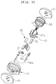
FIG. 3 is an exploded perspective view illustrating a vane motor according to one embodiment of the invention; -
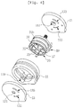
FIG. 4 is a perspective view of the vane motor showing an assembled state of the rotor and the inner liner inFIG. 3 ; -
FIG. 5 is a side view illustrating the assembled state of the rotor and the inner liner inFIG. 4 ; -
FIG. 6 is a fluoroscopic side view illustrating a relationship of the rotor, the inner liner, a fluid inlet and a fluid outlet which are provided on a finish plate engaged to the rotor and the inner liner; and -
FIG. 7 is a perspective view illustrating a rotor body including a rotational shaft of the vane motor. - Repeated use of reference characters throughout the present invention and appended drawings is intended to represent the same or analogous features or elements of the invention.
- Hereinafter, preferred embodiments of the invention will be explained in detail in conjunction with the accompanying drawings.
- Referring to a vane motor according to the embodiment illustrated in
FIGS. 2 to 7 ,
{29} thevane motor 1 of this embodiment includes a casing forming an exterior, aninner liner 20 of a cylindrical shape, and a rotor positioned in theinner liner 20. - The casing includes a
casing body 11 formed of a substantially cylindrical shape, andfinish plates casing body 11 in a longitudinal direction. Thefinish plates shaft mounting holes 131 and 151, through which arotational shaft 33 connected to the rotor passes, arc-shaped fluid inlets shaped fluid outlets bearing 17 is installed in the rotationalshaft mounting holes 131 and 151, so that therotational shaft 33 does not come into direct contact with thefinish plates rotational shaft 33 and thefinish plates - The
inner liner 20 is installed in the casing. The length of theinner liner 20 is substantially identical to that of thecasing body 11, and both ends of theinner liner 20 contact against the inner surfaces of thefinish plates inner liner 20 turns in the casing, the inner liner produces sliding friction between the inner surfaces of thefinish plates inner liner 20 is laid on a plurality of rollingmembers 19 which are disposed on aconcave portion 119 formed on the inner wall of thecasing wall 11, when theinner liner 20 is installed in the casing. The rolling member has aroller 19a and a rollingshaft 19b, and the rollingshaft 19b is formed in the shape of a cylinder or a rotational shaft, and is rotatably installed in parallel with therotational shaft 33. If theinner liner 20 turns in thecasing body 11, the rolling shaft coming into contact with the outer surface of the inner liner rotates, and thus there is no sliding friction between the turninginner liner 20 and the inner surface of thecasing body 11. - The rotor is installed in the
inner liner 20, and includes acylindrical rotor body 31 having therotational shaft 33, and a plurality ofvanes 35 engaged with eachgroove 31a of therotor body 31. The length of the cylinder forming therotor body 31 is substantially identical to that of thecasing body 11, and when the rotor turns, both ends of the cylinder come into contact with the inner surfaces of thefinish plates finish plates - The connecting manner between the
rotor body 31 and thevane 35 may be substantially identical to that of the vane motor of the prior art. Since the operation of thevane 35 in thegroove 31a is widely known in the art, the detailed description will be omitted herein. - This embodiment is substantially identical to the first embodiment, except that the rotor is not installed to come into directly contact with the inner surface of the
casing body 11, but is installed to come into directly contact with the inner surface of theinner liner 20. - The
rotational shaft 33 of the rotor is parallel with an imaginary rotational axis of theinner liner 20, but is spaced apart from the rotational axis of the inner liner at a distance. Thefinish plates rotational shaft 33 penetrates. The position of the hole is spaced apart from the rotational axis of the cylinder forming the casing at a distance. - With the above configuration, the rotor disposed in the
casing body 11 pushes theinner liner 20 of the cylindrical shape against the rollingmember 19 of thecasing body 11, so that an imaginary rotational axis of the cylinder forming the casing body is spaced apart from the imaginary rotational axis of theinner liner 20 of the cylindrical shape at an interval. The distance between therotor body 31 and the inner wall surface of theinner liner 20 is minimized at the position where the rotor pushes theinner liner 20, and thus thevane 35 is completely inserted in thegroove 31a so that therotor body 31 contacts against theinner liner 20, or a protruding length of thevane 35 from therotor body 31 is decreased. At the opposite side (an opposite side on the basis of the rotational shaft), the distance between therotor body 31 and the inner surface of theinner liner 20 is maximized, thereby increasing the protruding length of thevane 35 from therotor body 31. - The
groove 31a may be formed in various shapes, if necessary, and thevane 35 slidably moving in or out along thegroove 31a may be provided in a direction perpendicular to a vertical plane of thecylindrical rotor body 31, but protrudes at a desired angle with respect to the vertical plane. In this embodiment, the groove is formed on an outer peripheral surface of therotor body 31 along the entire length thereof in the longitudinal direction, and is slightly sloped at a desired angle with respect to a radial direction pointing along a radius from therotational shaft 33 toward the rotational direction of the rotor. Therefore, the vane protrudes at a desired angle toward the rotational direction with respect to the vertical plane of the rotor body.(added - The operation of components of the vane motor with the above configuration will now be described. A supplier for supplying the pressurized fluid to the
fluid inlets fluid outlets rotor body 31 and thevanes 35 of the rotor are not operated in thecasing body 11, but is operated in theinner liner 20. - Specifically, explaining the operation of components in the vane motor with the above configuration, the fluid inlet of the vane motor is connected with the supplier (not illustrated) for supplying the pressurized fluid from the outside. Since both of the
finish plates fluid inlets fluid outlets finish plates finish plates - Specifically, if the arc-shaped
fluid inlets inner liner 20 is gradually increased from the positions of thefluid inlets vane 35 protrudes at the most from thegroove 31a, so that the pressure applied to the vane is gradually increased. Since the arc-shapedfluid outlets - The rotor of this embodiment is rotated by the pressure difference, similar to the rotor of the vane motor according to the prior art, but the
inner liner 20 of the cylindrical shape forms the space in which the pressurized fluid operates, instead of the casing. Since the inner liner is not stationary, the rotational force is transferred to theinner liner 20 of the cylindrical shape which comes into contact with the distal end of thevane 35, due to the friction, when the rotor turns. Theinner liner 20 is rotated at the nearly equal linear velocity at the position of the distal end of the respective vanes which forms the outermost circumference of the rotor. - The inner liner is rotated in the casing, and the rolling
members 19, such as a rolling shaft, are interposed between the inner liner and the casing to reduce the sliding friction between the inner liner and thecasing body 11. - As a result, the abrasion caused by the sliding between the vane and the inner wall surface of the inner liner and the energy consumed by the frictional heat are decreased, and thus the efficiency of producing the rotational force by the pressurized fluid is increased.
- Of course, since the
finish plates inner liner 20 of the cylindrical shape which come into contact with the finish plates are rotated, both ends of the inner liner, therotor body 31 and the vanes come into slidable contact with the finish plates to produce the frictional heat and consume the energy. As compared to the prior art, the energy consumed by the friction is decreased. In order to further improve the efficiency, the size and surface of the finish plates, the rotor body and the vane should be maintained, similar to the prior art, and thebearing 17 is interposed between the finish plates of the casing and the rotational shafts to reduce the friction. - While the present invention has been described with reference to the particular illustrative embodiments, it is not to be restricted by the embodiments but only by the appended claims.
- It is to be appreciated that those skilled in the art can change or modify the embodiments without departing from the scope and spirit of the present invention.
-
- 11:
- Casing body
- 13, 15:
- Finish plate
- 17:
- Bearing
- 19:
- Rolling member
- 19a:
- Roller
- 19b:
- Rolling shaft
- 20:
- Inner liner
- 31, 231:
- Rotor body
- 31a, 231a:
- Groove
- 31b:
- Enlarged portion
- 33, 233:
- Rotational shaft
- 35, 235:
- Vane
- 119:
- Concave portion
- 135, 155, 253:
- Fluid inlet
- 133, 153, 255:
- Fluid outlet
- 211:
- Casing
Claims (3)
- A vane motor comprising:a casing including an inlet port and an outlet port, through which a pressurized fluid comes in or out;a rotor being installed in the casing, turning around a rotational shaft by the pressurized fluid and including a rotor body which has a substantially cylindrical shape and an axis coinciding with an axis of the rotational shaft and a plurality of vanes which is installed in grooves formed on an outer circumferential surface of the rotor body and has a portion protruding from the groove and (the portion) having a length varied in accordance with a rotational phase, andan inner liner of a cylindrical shape which is installed in the casing and receives the rotor therein, in which a distal end of the vane comes into contact with an inner wall surface of the inner liner while the pressurized fluid is retained therein until the pressurized fluid flowing through the inlet port of the casing is discharged from the outlet port of the casing, and an imaginary rotational axis of the inner liner is spaced apart from a rotational axis of the rotational shaft in a parallel state, but is able to rotate together with the rotor when the rotor turns.
- The vane motor according to claim 1, wherein the imaginary rotational axis of the inner liner and the rotational shaft of the rotor are maintained at constant positions and a rolling member which, when the inner liner is rotated in the casing, is interposed between an outer surface of the inner liner and the inner wall surface of the casing to reduce friction therebetween is included.
- The vane motor according to claim 1 or 2, whereinthe casing is configured in such a way that both ends of an outer liner of a cylindrical shape larger than the inner liner are closed by disc-shaped finish plates,at least one of the finish plates is configured in such a way that the rotational shaft pass through and is exposed out of the finish plate to transmit the rotational force, and a bearing is mounted between the rotational shaft and the finish plate.there is a fine gap in axial (longitudinal) direction between the finish plates and components including the inner liner and the vanes, so that the inner liner and the vanes are able to slide with the finish plates, but the pressurized fluid is hardly leaked through the gap.at least one of the finish plates may be provided with a fluid inlet and a fluid outlet. and the fluid inlet and the fluid outlet are formed in such a way that at least a portion of the fluid inlet and at least a portion of the fluid outlet are overlapped with a gap or space between the inner liner and the rotor body, when seen in an axial direction, and the fluid inlet and the fluid outlet are extended in an arc shape in a circumferential direction.
Applications Claiming Priority (1)
| Application Number | Priority Date | Filing Date | Title |
|---|---|---|---|
| KR1020190171084A KR102227744B1 (en) | 2019-12-19 | 2019-12-19 | vane motor |
Publications (2)
| Publication Number | Publication Date |
|---|---|
| EP3839206A1 true EP3839206A1 (en) | 2021-06-23 |
| EP3839206B1 EP3839206B1 (en) | 2024-11-20 |
Family
ID=69960186
Family Applications (1)
| Application Number | Title | Priority Date | Filing Date |
|---|---|---|---|
| EP20020102.8A Active EP3839206B1 (en) | 2019-12-19 | 2020-03-05 | Vane motor |
Country Status (7)
| Country | Link |
|---|---|
| US (1) | US20220290566A1 (en) |
| EP (1) | EP3839206B1 (en) |
| JP (1) | JP2023508892A (en) |
| KR (1) | KR102227744B1 (en) |
| CN (1) | CN115053049A (en) |
| CA (1) | CA3161397A1 (en) |
| WO (1) | WO2021125462A1 (en) |
Families Citing this family (9)
| Publication number | Priority date | Publication date | Assignee | Title |
|---|---|---|---|---|
| KR102491034B1 (en) * | 2021-02-19 | 2023-01-26 | 이엑스디엘 주식회사 | vane motor |
| KR102491036B1 (en) * | 2021-03-15 | 2023-01-26 | 이엑스디엘 주식회사 | vane motor system |
| KR102491035B1 (en) * | 2021-03-15 | 2023-01-26 | 이엑스디엘 주식회사 | vane motor |
| KR102555770B1 (en) | 2021-08-12 | 2023-07-20 | 이엑스디엘 주식회사 | power system using pressed gas and liquid |
| KR102555769B1 (en) | 2021-08-12 | 2023-07-20 | 이엑스디엘 주식회사 | power system using multi range of gas pressure |
| KR102617006B1 (en) * | 2021-10-14 | 2023-12-27 | 이엑스디엘 주식회사 | cocentric air motor |
| CN115199338A (en) * | 2022-06-30 | 2022-10-18 | 宁波郡邦新材料有限公司 | A new type of energy transfer device that converts potential energy into mechanical energy |
| WO2025073020A1 (en) * | 2023-10-02 | 2025-04-10 | Pereira Duarte Daniel Pedro | Hydraulic swing-piston motor |
| US12158101B1 (en) * | 2024-03-05 | 2024-12-03 | Adel Al-Subaih | Internal continuous combustion rotary engine |
Citations (5)
| Publication number | Priority date | Publication date | Assignee | Title |
|---|---|---|---|---|
| GB2140088A (en) * | 1983-03-31 | 1984-11-21 | Mitsubishi Electric Corp | Sliding-vane pump with rotating liner |
| EP0224878A2 (en) * | 1985-12-04 | 1987-06-10 | Kurt Gerhard Fickelscher | Machine for the compression and transport of fluids |
| WO2007102033A1 (en) * | 2006-03-06 | 2007-09-13 | Nebojsa Boskovic | Vane machine with stationary and rotating cylinder parts |
| KR101116511B1 (en) | 2011-10-05 | 2012-02-28 | 이병록 | Air vane motor with liner |
| KR101874583B1 (en) | 2016-06-24 | 2018-07-04 | 김재호 | Vane motor |
Family Cites Families (15)
| Publication number | Priority date | Publication date | Assignee | Title |
|---|---|---|---|---|
| US1528075A (en) * | 1921-08-11 | 1925-03-03 | Joseph R Richer | Rotary pump and the like |
| US2658456A (en) * | 1948-07-29 | 1953-11-10 | Gunnar A Wahlmark | Fluid displacement device |
| US2891482A (en) * | 1956-12-01 | 1959-06-23 | Emanuel Di Giuseppe E Roberto | Rotary machine adapted to operate as a pump or as a fluid motor |
| US3437079A (en) * | 1963-12-17 | 1969-04-08 | Daisaku Odawara | Rotary machine of blade type |
| JPS4825131U (en) * | 1971-08-04 | 1973-03-24 | ||
| JPH02130282A (en) * | 1988-11-08 | 1990-05-18 | Mitsuo Okamoto | Vane hydraulic pump having cam ring floating structure and vane hydraulic motor |
| JPH081549A (en) * | 1994-06-24 | 1996-01-09 | Uriyuu Seisaku Kk | Air motor |
| JPH0821373A (en) * | 1994-07-07 | 1996-01-23 | Isao Suzuki | Pump with blade fixed structurally in pump chamber |
| CN1163651A (en) * | 1994-08-23 | 1997-10-29 | 丹提卡特国际有限公司 | Fluid reaction device |
| JPH08144701A (en) * | 1994-11-18 | 1996-06-04 | Uriyuu Seisaku Kk | Air motor |
| US6135742A (en) * | 1998-08-28 | 2000-10-24 | Cho; Bong-Hyun | Eccentric-type vane pump |
| KR20030072497A (en) * | 2002-03-04 | 2003-09-15 | 한국기계연구원 | Pneumatic vane motor |
| JP2009041395A (en) * | 2007-08-07 | 2009-02-26 | Nippon Telegr & Teleph Corp <Ntt> | Rotating device |
| KR101175713B1 (en) * | 2012-05-23 | 2012-08-21 | 정의섭 | Vane motor using high-pressure fluid and apparatus for generating electricity having the same |
| US9206688B2 (en) * | 2013-07-10 | 2015-12-08 | Spx Flow, Inc. | High torque rotary motor with multi-lobed ring with inlet and outlet |
-
2019
- 2019-12-19 KR KR1020190171084A patent/KR102227744B1/en active Active
-
2020
- 2020-03-05 EP EP20020102.8A patent/EP3839206B1/en active Active
- 2020-06-01 CN CN202080087407.6A patent/CN115053049A/en active Pending
- 2020-06-01 CA CA3161397A patent/CA3161397A1/en active Pending
- 2020-06-01 JP JP2022537444A patent/JP2023508892A/en active Pending
- 2020-06-01 WO PCT/KR2020/007092 patent/WO2021125462A1/en not_active Ceased
-
2022
- 2022-06-03 US US17/831,652 patent/US20220290566A1/en not_active Abandoned
Patent Citations (5)
| Publication number | Priority date | Publication date | Assignee | Title |
|---|---|---|---|---|
| GB2140088A (en) * | 1983-03-31 | 1984-11-21 | Mitsubishi Electric Corp | Sliding-vane pump with rotating liner |
| EP0224878A2 (en) * | 1985-12-04 | 1987-06-10 | Kurt Gerhard Fickelscher | Machine for the compression and transport of fluids |
| WO2007102033A1 (en) * | 2006-03-06 | 2007-09-13 | Nebojsa Boskovic | Vane machine with stationary and rotating cylinder parts |
| KR101116511B1 (en) | 2011-10-05 | 2012-02-28 | 이병록 | Air vane motor with liner |
| KR101874583B1 (en) | 2016-06-24 | 2018-07-04 | 김재호 | Vane motor |
Also Published As
| Publication number | Publication date |
|---|---|
| JP2023508892A (en) | 2023-03-06 |
| WO2021125462A1 (en) | 2021-06-24 |
| US20220290566A1 (en) | 2022-09-15 |
| CN115053049A (en) | 2022-09-13 |
| CA3161397A1 (en) | 2021-06-24 |
| KR102227744B1 (en) | 2021-03-15 |
| EP3839206B1 (en) | 2024-11-20 |
Similar Documents
| Publication | Publication Date | Title |
|---|---|---|
| US20220290566A1 (en) | Vane motor | |
| US5022842A (en) | Vane pump with rotatable annular ring means to control vane extension | |
| US4451215A (en) | Rotary piston apparatus | |
| HU210369B (en) | Machine with rotating blades | |
| US4917584A (en) | Vane pump with annular aetainer limiting outward radial vane movement | |
| EP1540174B1 (en) | Cam ring bearing for fuel delivery system | |
| GB2197689A (en) | Rotary sliding-vane pumps | |
| CN101454573B (en) | Vane machine | |
| US10260604B2 (en) | Speed increaser | |
| EP3839207B1 (en) | Vane motor | |
| US20170268509A1 (en) | Vane Pump Assembly | |
| US7192264B2 (en) | Hyrdraulic motor | |
| KR102747674B1 (en) | Turbo compressor | |
| US4561835A (en) | Floating rotary sleeve of a rotary compressor | |
| US4573891A (en) | Rotary sleeve of a rotary compressor | |
| JPH0329995B2 (en) | ||
| KR102491034B1 (en) | vane motor | |
| JP3181244B2 (en) | Vane type fluid motor | |
| CN210218112U (en) | Oil-free lubrication rotary vane vacuum pump | |
| KR100515717B1 (en) | Two stage and non-contacting type rotor device for air tools | |
| GB2197389A (en) | Rotary vane pumps | |
| JP7155429B2 (en) | Variable nozzle device and variable capacity exhaust turbocharger | |
| WO2024013716A1 (en) | Volumetric rotary pump | |
| GB2571794A (en) | Split blane vane pump | |
| CN101087960A (en) | Variable delivery vane pump, in particular for oil |
Legal Events
| Date | Code | Title | Description |
|---|---|---|---|
| PUAI | Public reference made under article 153(3) epc to a published international application that has entered the european phase |
Free format text: ORIGINAL CODE: 0009012 |
|
| STAA | Information on the status of an ep patent application or granted ep patent |
Free format text: STATUS: THE APPLICATION HAS BEEN PUBLISHED |
|
| AK | Designated contracting states |
Kind code of ref document: A1 Designated state(s): AL AT BE BG CH CY CZ DE DK EE ES FI FR GB GR HR HU IE IS IT LI LT LU LV MC MK MT NL NO PL PT RO RS SE SI SK SM TR |
|
| STAA | Information on the status of an ep patent application or granted ep patent |
Free format text: STATUS: REQUEST FOR EXAMINATION WAS MADE |
|
| 17P | Request for examination filed |
Effective date: 20211223 |
|
| RBV | Designated contracting states (corrected) |
Designated state(s): AL AT BE BG CH CY CZ DE DK EE ES FI FR GB GR HR HU IE IS IT LI LT LU LV MC MK MT NL NO PL PT RO RS SE SI SK SM TR |
|
| STAA | Information on the status of an ep patent application or granted ep patent |
Free format text: STATUS: EXAMINATION IS IN PROGRESS |
|
| 17Q | First examination report despatched |
Effective date: 20230317 |
|
| GRAP | Despatch of communication of intention to grant a patent |
Free format text: ORIGINAL CODE: EPIDOSNIGR1 |
|
| STAA | Information on the status of an ep patent application or granted ep patent |
Free format text: STATUS: GRANT OF PATENT IS INTENDED |
|
| INTG | Intention to grant announced |
Effective date: 20240618 |
|
| GRAS | Grant fee paid |
Free format text: ORIGINAL CODE: EPIDOSNIGR3 |
|
| GRAA | (expected) grant |
Free format text: ORIGINAL CODE: 0009210 |
|
| STAA | Information on the status of an ep patent application or granted ep patent |
Free format text: STATUS: THE PATENT HAS BEEN GRANTED |
|
| AK | Designated contracting states |
Kind code of ref document: B1 Designated state(s): AL AT BE BG CH CY CZ DE DK EE ES FI FR GB GR HR HU IE IS IT LI LT LU LV MC MK MT NL NO PL PT RO RS SE SI SK SM TR |
|
| REG | Reference to a national code |
Ref country code: GB Ref legal event code: FG4D |
|
| REG | Reference to a national code |
Ref country code: CH Ref legal event code: EP |
|
| REG | Reference to a national code |
Ref country code: DE Ref legal event code: R096 Ref document number: 602020041524 Country of ref document: DE |
|
| REG | Reference to a national code |
Ref country code: IE Ref legal event code: FG4D |
|
| REG | Reference to a national code |
Ref country code: DE Ref legal event code: R082 Ref document number: 602020041524 Country of ref document: DE Representative=s name: PA-MUNK, DE |
|
| REG | Reference to a national code |
Ref country code: LT Ref legal event code: MG9D |
|
| REG | Reference to a national code |
Ref country code: NL Ref legal event code: MP Effective date: 20241120 |
|
| PG25 | Lapsed in a contracting state [announced via postgrant information from national office to epo] |
Ref country code: HR Free format text: LAPSE BECAUSE OF FAILURE TO SUBMIT A TRANSLATION OF THE DESCRIPTION OR TO PAY THE FEE WITHIN THE PRESCRIBED TIME-LIMIT Effective date: 20241120 Ref country code: PT Free format text: LAPSE BECAUSE OF FAILURE TO SUBMIT A TRANSLATION OF THE DESCRIPTION OR TO PAY THE FEE WITHIN THE PRESCRIBED TIME-LIMIT Effective date: 20250320 Ref country code: IS Free format text: LAPSE BECAUSE OF FAILURE TO SUBMIT A TRANSLATION OF THE DESCRIPTION OR TO PAY THE FEE WITHIN THE PRESCRIBED TIME-LIMIT Effective date: 20250320 |
|
| PGFP | Annual fee paid to national office [announced via postgrant information from national office to epo] |
Ref country code: DE Payment date: 20250331 Year of fee payment: 6 |
|
| PG25 | Lapsed in a contracting state [announced via postgrant information from national office to epo] |
Ref country code: FI Free format text: LAPSE BECAUSE OF FAILURE TO SUBMIT A TRANSLATION OF THE DESCRIPTION OR TO PAY THE FEE WITHIN THE PRESCRIBED TIME-LIMIT Effective date: 20241120 Ref country code: NL Free format text: LAPSE BECAUSE OF FAILURE TO SUBMIT A TRANSLATION OF THE DESCRIPTION OR TO PAY THE FEE WITHIN THE PRESCRIBED TIME-LIMIT Effective date: 20241120 |
|
| REG | Reference to a national code |
Ref country code: AT Ref legal event code: MK05 Ref document number: 1743735 Country of ref document: AT Kind code of ref document: T Effective date: 20241120 |
|
| PG25 | Lapsed in a contracting state [announced via postgrant information from national office to epo] |
Ref country code: BG Free format text: LAPSE BECAUSE OF FAILURE TO SUBMIT A TRANSLATION OF THE DESCRIPTION OR TO PAY THE FEE WITHIN THE PRESCRIBED TIME-LIMIT Effective date: 20241120 |
|
| PG25 | Lapsed in a contracting state [announced via postgrant information from national office to epo] |
Ref country code: ES Free format text: LAPSE BECAUSE OF FAILURE TO SUBMIT A TRANSLATION OF THE DESCRIPTION OR TO PAY THE FEE WITHIN THE PRESCRIBED TIME-LIMIT Effective date: 20241120 |
|
| PG25 | Lapsed in a contracting state [announced via postgrant information from national office to epo] |
Ref country code: NO Free format text: LAPSE BECAUSE OF FAILURE TO SUBMIT A TRANSLATION OF THE DESCRIPTION OR TO PAY THE FEE WITHIN THE PRESCRIBED TIME-LIMIT Effective date: 20250220 |
|
| PG25 | Lapsed in a contracting state [announced via postgrant information from national office to epo] |
Ref country code: GR Free format text: LAPSE BECAUSE OF FAILURE TO SUBMIT A TRANSLATION OF THE DESCRIPTION OR TO PAY THE FEE WITHIN THE PRESCRIBED TIME-LIMIT Effective date: 20250221 Ref country code: AT Free format text: LAPSE BECAUSE OF FAILURE TO SUBMIT A TRANSLATION OF THE DESCRIPTION OR TO PAY THE FEE WITHIN THE PRESCRIBED TIME-LIMIT Effective date: 20241120 Ref country code: LV Free format text: LAPSE BECAUSE OF FAILURE TO SUBMIT A TRANSLATION OF THE DESCRIPTION OR TO PAY THE FEE WITHIN THE PRESCRIBED TIME-LIMIT Effective date: 20241120 |
|
| PG25 | Lapsed in a contracting state [announced via postgrant information from national office to epo] |
Ref country code: PL Free format text: LAPSE BECAUSE OF FAILURE TO SUBMIT A TRANSLATION OF THE DESCRIPTION OR TO PAY THE FEE WITHIN THE PRESCRIBED TIME-LIMIT Effective date: 20241120 |
|
| PGFP | Annual fee paid to national office [announced via postgrant information from national office to epo] |
Ref country code: FR Payment date: 20250324 Year of fee payment: 6 |
|
| PGFP | Annual fee paid to national office [announced via postgrant information from national office to epo] |
Ref country code: GB Payment date: 20250324 Year of fee payment: 6 |
|
| PG25 | Lapsed in a contracting state [announced via postgrant information from national office to epo] |
Ref country code: RS Free format text: LAPSE BECAUSE OF FAILURE TO SUBMIT A TRANSLATION OF THE DESCRIPTION OR TO PAY THE FEE WITHIN THE PRESCRIBED TIME-LIMIT Effective date: 20250220 |
|
| PG25 | Lapsed in a contracting state [announced via postgrant information from national office to epo] |
Ref country code: SM Free format text: LAPSE BECAUSE OF FAILURE TO SUBMIT A TRANSLATION OF THE DESCRIPTION OR TO PAY THE FEE WITHIN THE PRESCRIBED TIME-LIMIT Effective date: 20241120 |
|
| PG25 | Lapsed in a contracting state [announced via postgrant information from national office to epo] |
Ref country code: DK Free format text: LAPSE BECAUSE OF FAILURE TO SUBMIT A TRANSLATION OF THE DESCRIPTION OR TO PAY THE FEE WITHIN THE PRESCRIBED TIME-LIMIT Effective date: 20241120 |
|
| PG25 | Lapsed in a contracting state [announced via postgrant information from national office to epo] |
Ref country code: EE Free format text: LAPSE BECAUSE OF FAILURE TO SUBMIT A TRANSLATION OF THE DESCRIPTION OR TO PAY THE FEE WITHIN THE PRESCRIBED TIME-LIMIT Effective date: 20241120 |
|
| PG25 | Lapsed in a contracting state [announced via postgrant information from national office to epo] |
Ref country code: RO Free format text: LAPSE BECAUSE OF FAILURE TO SUBMIT A TRANSLATION OF THE DESCRIPTION OR TO PAY THE FEE WITHIN THE PRESCRIBED TIME-LIMIT Effective date: 20241120 |
|
| PG25 | Lapsed in a contracting state [announced via postgrant information from national office to epo] |
Ref country code: SK Free format text: LAPSE BECAUSE OF FAILURE TO SUBMIT A TRANSLATION OF THE DESCRIPTION OR TO PAY THE FEE WITHIN THE PRESCRIBED TIME-LIMIT Effective date: 20241120 |
|
| PG25 | Lapsed in a contracting state [announced via postgrant information from national office to epo] |
Ref country code: CZ Free format text: LAPSE BECAUSE OF FAILURE TO SUBMIT A TRANSLATION OF THE DESCRIPTION OR TO PAY THE FEE WITHIN THE PRESCRIBED TIME-LIMIT Effective date: 20241120 |
|
| PG25 | Lapsed in a contracting state [announced via postgrant information from national office to epo] |
Ref country code: IT Free format text: LAPSE BECAUSE OF FAILURE TO SUBMIT A TRANSLATION OF THE DESCRIPTION OR TO PAY THE FEE WITHIN THE PRESCRIBED TIME-LIMIT Effective date: 20241120 |
|
| REG | Reference to a national code |
Ref country code: DE Ref legal event code: R097 Ref document number: 602020041524 Country of ref document: DE |
|
| PG25 | Lapsed in a contracting state [announced via postgrant information from national office to epo] |
Ref country code: SE Free format text: LAPSE BECAUSE OF FAILURE TO SUBMIT A TRANSLATION OF THE DESCRIPTION OR TO PAY THE FEE WITHIN THE PRESCRIBED TIME-LIMIT Effective date: 20241120 |
|
| PLBE | No opposition filed within time limit |
Free format text: ORIGINAL CODE: 0009261 |
|
| STAA | Information on the status of an ep patent application or granted ep patent |
Free format text: STATUS: NO OPPOSITION FILED WITHIN TIME LIMIT |
|
| PG25 | Lapsed in a contracting state [announced via postgrant information from national office to epo] |
Ref country code: MC Free format text: LAPSE BECAUSE OF FAILURE TO SUBMIT A TRANSLATION OF THE DESCRIPTION OR TO PAY THE FEE WITHIN THE PRESCRIBED TIME-LIMIT Effective date: 20241120 |
|
| 26N | No opposition filed |
Effective date: 20250821 |
|
| REG | Reference to a national code |
Ref country code: CH Ref legal event code: H13 Free format text: ST27 STATUS EVENT CODE: U-0-0-H10-H13 (AS PROVIDED BY THE NATIONAL OFFICE) Effective date: 20251023 |
|
| PG25 | Lapsed in a contracting state [announced via postgrant information from national office to epo] |
Ref country code: LU Free format text: LAPSE BECAUSE OF NON-PAYMENT OF DUE FEES Effective date: 20250305 |
|
| REG | Reference to a national code |
Ref country code: BE Ref legal event code: MM Effective date: 20250331 |
|
| PG25 | Lapsed in a contracting state [announced via postgrant information from national office to epo] |
Ref country code: BE Free format text: LAPSE BECAUSE OF NON-PAYMENT OF DUE FEES Effective date: 20250331 |
|
| PG25 | Lapsed in a contracting state [announced via postgrant information from national office to epo] |
Ref country code: CH Free format text: LAPSE BECAUSE OF NON-PAYMENT OF DUE FEES Effective date: 20250331 |
|
| PG25 | Lapsed in a contracting state [announced via postgrant information from national office to epo] |
Ref country code: IE Free format text: LAPSE BECAUSE OF NON-PAYMENT OF DUE FEES Effective date: 20250305 |