EP3839082A1 - Device for fixing a ring, in particular a ring for large-diameter bearings, during the hardening of the ring, method for fixing a ring for hardening the ring - Google Patents
Device for fixing a ring, in particular a ring for large-diameter bearings, during the hardening of the ring, method for fixing a ring for hardening the ring Download PDFInfo
- Publication number
- EP3839082A1 EP3839082A1 EP19218007.3A EP19218007A EP3839082A1 EP 3839082 A1 EP3839082 A1 EP 3839082A1 EP 19218007 A EP19218007 A EP 19218007A EP 3839082 A1 EP3839082 A1 EP 3839082A1
- Authority
- EP
- European Patent Office
- Prior art keywords
- ring
- bottom plate
- plate
- jaws
- axial direction
- Prior art date
- Legal status (The legal status is an assumption and is not a legal conclusion. Google has not performed a legal analysis and makes no representation as to the accuracy of the status listed.)
- Pending
Links
- 238000000034 method Methods 0.000 title claims abstract description 24
- 239000002826 coolant Substances 0.000 claims description 28
- 238000003825 pressing Methods 0.000 claims description 25
- 125000006850 spacer group Chemical group 0.000 claims description 9
- 230000000295 complement effect Effects 0.000 description 4
- 238000003892 spreading Methods 0.000 description 2
- 229910000831 Steel Inorganic materials 0.000 description 1
- 230000006978 adaptation Effects 0.000 description 1
- 230000005540 biological transmission Effects 0.000 description 1
- 238000001816 cooling Methods 0.000 description 1
- 230000008878 coupling Effects 0.000 description 1
- 238000010168 coupling process Methods 0.000 description 1
- 238000005859 coupling reaction Methods 0.000 description 1
- 230000001419 dependent effect Effects 0.000 description 1
- 230000002349 favourable effect Effects 0.000 description 1
- 238000002360 preparation method Methods 0.000 description 1
- 238000005096 rolling process Methods 0.000 description 1
- 239000010959 steel Substances 0.000 description 1
Images



Classifications
-
- C—CHEMISTRY; METALLURGY
- C21—METALLURGY OF IRON
- C21D—MODIFYING THE PHYSICAL STRUCTURE OF FERROUS METALS; GENERAL DEVICES FOR HEAT TREATMENT OF FERROUS OR NON-FERROUS METALS OR ALLOYS; MAKING METAL MALLEABLE, e.g. BY DECARBURISATION OR TEMPERING
- C21D1/00—General methods or devices for heat treatment, e.g. annealing, hardening, quenching or tempering
- C21D1/06—Surface hardening
-
- C—CHEMISTRY; METALLURGY
- C21—METALLURGY OF IRON
- C21D—MODIFYING THE PHYSICAL STRUCTURE OF FERROUS METALS; GENERAL DEVICES FOR HEAT TREATMENT OF FERROUS OR NON-FERROUS METALS OR ALLOYS; MAKING METAL MALLEABLE, e.g. BY DECARBURISATION OR TEMPERING
- C21D1/00—General methods or devices for heat treatment, e.g. annealing, hardening, quenching or tempering
- C21D1/18—Hardening; Quenching with or without subsequent tempering
-
- C—CHEMISTRY; METALLURGY
- C21—METALLURGY OF IRON
- C21D—MODIFYING THE PHYSICAL STRUCTURE OF FERROUS METALS; GENERAL DEVICES FOR HEAT TREATMENT OF FERROUS OR NON-FERROUS METALS OR ALLOYS; MAKING METAL MALLEABLE, e.g. BY DECARBURISATION OR TEMPERING
- C21D9/00—Heat treatment, e.g. annealing, hardening, quenching or tempering, adapted for particular articles; Furnaces therefor
- C21D9/40—Heat treatment, e.g. annealing, hardening, quenching or tempering, adapted for particular articles; Furnaces therefor for rings; for bearing races
Definitions
- the present invention is based on a method for fixing a ring for hardening the ring, particularly hardening a ring for large-diameter bearings.
- Fixing large-sized rings, particular steel rings for large-sized rolling bearings, for hardening the rings is necessary to avoid deformation.
- the rings are clamped into preparations fixing the ring's geometry in axial and radial direction.
- document JP 2005 076 111 (A ) describes a method for hardening large-diameter rings during which the ring is supported by spring supported pistons.
- the devices for fixing large-diameter rings known from the prior art is that the devices exhibit complex mechanics, are thus expensive and need care and servicing.
- a device for fixing a ring in particular a ring for large-diameter bearings, during the hardening of the ring
- the device comprises a bottom plate having a main extension plane, an expanding ring movable in an axial direction orthogonal to the main extension plane, and jaws movable in a radial direction orthogonal to the axial direction, the device being configured such that movement of the expanding ring in an axial direction towards the bottom plate leads to movement of the jaws in a radial direction away from a center of the bottom plate outwards.
- the device according to the invention provides an efficient way to fix a ring by clamping the ring by exerting radial pressure on the inside of the ring by the jaws. For this, force is transmitted by moving the spreading ring in axial direction towards the bottom plate onto the jaws.
- the device is preferably a device for fixing a large-diameter ring.
- a large-diameter ring in the sense of the present invention has an outer diameter of at least 2 meters, preferably 3 meters or more. It is also thinkable, that the device is used for fixing ring with a diameter of less than 2 meters.
- Outside and outwards in the sense of the present invention is directed in radial direction away from the centre of the bottom plate. Inside and inwards in the sense of the present invention is directed in radial direction towards the centre of the bottom plate.
- the jaws are arranged in the radial direction on an outside of the expanding ring, wherein an outside part of the expanding ring, which is oriented outwards in radial direction, has an upper conical region with an outwardly directed profile and a lower conical region with an inwardly directed profile, wherein an inside part of the jaws, which is towards the outside part of the expanding ring, has a further upper conical region with an outwardly directed profile and a further lower conical region with an inwardly directed profile.
- the upper conical region of the expansion ring and the upper conical region of the jaws are shaped complementary.
- the lower conical region of the expansion ring and the lower conical region of the jaws are shaped complementary.
- the expanding ring comprises spacers for limiting the movement of the expanding ring in the axial direction towards the bottom plate, wherein the spacers are preferably adjustable, wherein the spacers particularly preferably comprise screws.
- the device comprises pressing means for exerting mechanical pressure on the expanding ring in an axial direction towards the bottom plate.
- the expanding ring is arranged between the bottom plate and a press plate of the pressing means, wherein the press plate is arranged abutting the expanding ring. This makes it possible to apply a mechanical force uniformly all over the circumference of the expanding ring.
- the pressing means comprises a rod projecting centrally from the bottom plate and in the axial direction beyond the press plate, wherein the rod comprises an opening in the radial direction, wherein the opening is arranged in the axial direction on the side of the press plate remote from the bottom plate.
- the rod comprises a handle. This makes it possible to easily transport the device.
- the rod is arranged in a central opening of the bottom plate.
- the rod is fixed from-locking at the bottom plate.
- the pressing means comprises a wedge-shaped insert arranged in the opening, wherein the pressing means preferably comprises a force conducting ring between the insert and the pressing plate for transmitting mechanical pressure from the insert to the press plate.
- Wedge-shape in the sense of the present invention means wedge-shaped in a plane orthogonal to the main extension plane. This enables exerting a force on the press plate by inserting the insert into the opening.
- the force conducting ring avoids an unbalanced strain on the press plate.
- the pressing means comprises a further rods projecting from the bottom plate and in the axial direction beyond the press plate, wherein the further rods comprise further openings in the radial direction, wherein the further openings are arranged in the axial direction on the side of the press plate remote from the bottom plate, wherein the pressing means preferably comprises wedge-shaped further inserts arranged in the further openings, wherein the pressing means more preferably comprises further force conducting rings between the further inserts and the pressing plate for transmitting mechanical pressure from the further inserts to the pressing plate.
- the further rods are arranged equidistantly to each other. This enables homogenising the applied force on the press plate.
- the device comprises a centring plate, the centring plate being arranged in a radial direction abutting the expanding ring, the rod preferably being arranged in a central opening of the centring plate. This helps arranging the parts of the device and the ring concentrically.
- the jaws comprise coolant channels on their outside part, wherein the coolant channels are preferably arranged to extend in the axial direction.
- the coolant channels can be streamed through by a coolant medium, e.g., coolant oil.
- a coolant medium e.g., coolant oil.
- the bottom plate comprises bottom plate openings
- the press plate comprises press plate openings
- the centring plate comprises centring plate openings
- the bottom plate openings and/or the press plate openings and/or the centring plate openings are preferably arranged coaxially to one another.
- the bottom plate openings and/or the press plate openings and/or the centring plate openings allow a coolant medium to flow through the device. The can be helpful during the hardening procedure, when the ring has to be cooled down.
- the bottom plate comprises further coolant channels, wherein the further coolant channels are preferably arranged circularly around the centre of the bottom plate, wherein the jaws are preferably arranged relative to the radial direction between the further coolant channels and the expanding ring.
- the further coolant channels are arranged such, that a cooling medium flowing through the coolant channels directly contacts the ring. This enables an efficient cooling of the ring during the hardening process.
- the bottom plate comprises guides arranged in the radial direction for guiding the jaws, the jaws preferably comprising guide blocks, the guide blocks engaging in the guides. This enables a very precise guided movement of the jaws towards the ring.
- the expanding ring comprises a centering aid for centering the ring when disposed on the device.
- a further subject of the present invention for the solving of the problem initially presented is a method for fixing a ring for hardening the ring with a device according to the present invention, wherein the ring is disposed on the device, the inside of the ring facing the outside part of the jaws, wherein the expanding ring is moved in axial direction towards the bottom plate resulting in a movement of the jaws towards the ring, wherein the ring is fixed by the jaws abutting the inside of the ring.
- the method according to the invention provides an efficient way to fix the ring by clamping the ring by exerting radial pressure on the inside of the ring by the jaws. For this, force is transmitted by moving the spreading ring in axial direction towards the bottom plate onto the jaws.
- the ring has an outer diameter of at least 2 meters.
- the device is also possible to use for ring that has an outer diameter less than 2 m.
- the expanding ring is moved by inserting the insert into the opening and preferably by inserting the further inserts into the further openings.
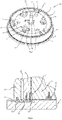
- FIG. 1 shows a schematic illustration of a device 100 according to an exemplary embodiment of the present invention and a method according to an exemplary embodiment of the present invention.
- the device 100 comprises a bottom plate 1 and a rod 2 attached to the bottom plate 1 at the centre O of the bottom plate 1.
- a main extension plane M of the bottom plate 1 is arranged parallel to a radial direction R and orthogonal to an axial direction A.
- the device 100 comprises an expanding ring 4, which is movable along the axial direction A and jaws 5 arranged along the outer circumference of the expanding ring 4.
- the jaws are movable in radial direction R.
- a ring 8 is arranged radially outside of the jaws 5 such, that the ring 8 can be radially clamped and fixed by a movement of the jaws 5 towards the ring 8 and the jaws 5 abutting the ring 8 and exerting pressure on the ring 8.
- the device 100 comprises a centring plate 6, which engages in a recess of the expanding ring 4 and aligns the expanding ring 4 coaxially to the rod 2.
- the rod 2 comprises a handle 22, which helps transporting the device 100.
- a wedge-shaped insert 3 is arranged in an opening 7 of the rod. Inserting the insert 3 in the opening from the left to the right with the upper edge of the insert 3 abutting the upper wall of the opening leads to a movement of the lower edge of the insert in direction of the bottom plate 1. It will be described how a force can be applied with the insert 3 in the ring 8 later referring to Fig. 8 .
- a centring aid 44 is arranged on the expanding ring 4. This will be shown in detail referring to Fig. 5 .
- FIG. 2 shows a schematic illustration of the device 100 according to an exemplary embodiment of the present invention and a method according to an exemplary embodiment of the present invention.
- a view parallel to the axial direction is shown.
- the centring plate 6 comprising centring plate openings 61.
- the further rods 21 comprise further openings 71 in which wedge-shaped further inserts 31 are arranged. This helps homogenizing the force that is exerted on the ring 8.
- a force conducting ring 92 and further force conducting rings 93 are arranged to avoid high local stress on parts of the device abutting the insert 3 and the further inserts 31.
- the jaws 5 comprise coolant channels 51, through which a coolant medium can flow to cool the ring 8 during the hardening process. Hinge screws 45 on the expanding ring 4 enable to easily lift and transport the expanding ring 4.
- Figure 3 shows another schematic illustration of the device 100 and the method shown in Figure 2 .
- FIG 4 shows a schematic illustration of a detail of the device 100 shown in Figure 3 .
- the coolant channels 51 and further coolant channels 12 can be seen.
- the further coolant channels 12 are arranged circularly around the centre of the bottom plate 1 such, that a cooling medium that flows through the further coolant channels 12 can directly cool down the ring 8 during the hardening process.
- the jaws 5 comprise a guide block 54 which engages in a guide 13 of the bottom plate 1.
- the outside part of the expanding ring 4 comprises a lower conical region 42.
- the lower conical region 42 has an inwardly directed profile.
- the jaws 5 also comprise a lower conical region 53 with an inwardly directed profile.
- the lower conical region 53 of the jaws and the lower conical region 42 of the expanding ring 4 are shaped complementary. Hence, a movement of the expanding ring 4 towards the bottom plate 1 causes a movement of the jaws 5 towards the ring 8.
- the movement of the expanding ring 8 towards the bottom plate 1 can be limited by a spacer 43.
- the spacer 43 comprises a screw, which can be adjusted by screwing in or out.
- FIG. 5 shows a schematic illustration of another detail of the device 100 shown in Figure 3 .
- the outside part of the expanding ring 4 comprises an upper conical region 41.
- the upper conical region 41 of the expanding ring 4 has an outwardly directed profile.
- the jaws 5 also comprise an upper conical region 52 with an outwardly directed profile.
- the upper conical region 52 of the jaws and the upper conical region 41 of the expanding ring 4 are shaped complementary.
- a movement of the expanding ring 4 downwards, i.e. towards the bottom plate (not shown here) causes a movement of the jaws 5 towards the ring 8.
- the expanding ring 4 comprises a centring aid 44 to simplify the mounting of the ring 8 on the device 100.
- the centring aid 44 comprises a bevelled edge that centres the ring 8 when it is placed on the device 100. With this, less care must be taken when preparing the hardening of the ring 8 and damage to the device 100 and the ring 8 is avoided.
- FIG 7 shows a schematic perspective illustration of the device 100 shown in Figure 3 as cross-sectional view with all the features already discussed above.
- the centring plate openings 61 and the bottom plate openings 11 are arranged coaxially. This enables a good flow through the device, for example with a cooling medium.
- FIG 8 shows a schematic perspective illustration of the device 100 shown in Figure 3 as cross-sectional view.
- the centring plate openings 61 and the bottom plate openings 11 are arranged coaxially. This enables a good flow through the device, for example with a cooling medium.
- a press plate 9 of the device 100 is shown here.
- the press plate 9 covers the centring plate 6.
- the press plate 9 comprises press plate openings 91 which are arranged coaxially with the bottom plate openings and the centring plate openings (not visible here).
- the wedge-shaped insert 3 and the wedge-shaped further inserts 31 are pushed into the opening 7 of the rod 2 or into the further openings 71 of the further rods, respectively, these exert a force on the force conducting ring 92 or the further force conducting rings 93 (here, only one further force conducting ring is shown).
- the force is evenly transmitted by the force conducting rings 92, 93 to the press plate 9 and leads to a pressure on the expanding ring 4 in the direction of the bottom plate 1.
- the pressure on the expanding ring 4 causes the jaws 5 to move towards the ring 8 and clamp the ring 8 to fix it for the hardening procedure.
Landscapes
- Chemical & Material Sciences (AREA)
- Engineering & Computer Science (AREA)
- Physics & Mathematics (AREA)
- Thermal Sciences (AREA)
- Crystallography & Structural Chemistry (AREA)
- Mechanical Engineering (AREA)
- Materials Engineering (AREA)
- Metallurgy (AREA)
- Organic Chemistry (AREA)
- Heat Treatment Of Articles (AREA)
Abstract
Description
- The present invention is based on a method for fixing a ring for hardening the ring, particularly hardening a ring for large-diameter bearings.
- Fixing large-sized rings, particular steel rings for large-sized rolling bearings, for hardening the rings is necessary to avoid deformation. Usually, the rings are clamped into preparations fixing the ring's geometry in axial and radial direction. For example, document
JP 2005 076 111 (A - It is a purpose of the present invention to provide a device for fixing a ring, in particular a ring for large-diameter bearings, during the hardening of the ring which does not suffer from the disadvantages of the prior art described above, but is robust and needs only little servicing.
- This is solved by a device for fixing a ring, in particular a ring for large-diameter bearings, during the hardening of the ring, wherein the device comprises a bottom plate having a main extension plane, an expanding ring movable in an axial direction orthogonal to the main extension plane, and jaws movable in a radial direction orthogonal to the axial direction, the device being configured such that movement of the expanding ring in an axial direction towards the bottom plate leads to movement of the jaws in a radial direction away from a center of the bottom plate outwards.
- The device according to the invention provides an efficient way to fix a ring by clamping the ring by exerting radial pressure on the inside of the ring by the jaws. For this, force is transmitted by moving the spreading ring in axial direction towards the bottom plate onto the jaws. The device is preferably a device for fixing a large-diameter ring. A large-diameter ring in the sense of the present invention has an outer diameter of at least 2 meters, preferably 3 meters or more. It is also thinkable, that the device is used for fixing ring with a diameter of less than 2 meters.
- Outside and outwards in the sense of the present invention is directed in radial direction away from the centre of the bottom plate. Inside and inwards in the sense of the present invention is directed in radial direction towards the centre of the bottom plate.
- Favourable embodiments and further adaptations of the invention are deducible from the dependent claims as well as from the description with reference to the drawings.
- In accordance with a preferred embodiment of the present invention, it is provided that the jaws are arranged in the radial direction on an outside of the expanding ring, wherein an outside part of the expanding ring, which is oriented outwards in radial direction, has an upper conical region with an outwardly directed profile and a lower conical region with an inwardly directed profile, wherein an inside part of the jaws, which is towards the outside part of the expanding ring, has a further upper conical region with an outwardly directed profile and a further lower conical region with an inwardly directed profile. This enables a good transmission of force from the expansion ring to the jaws. Preferably, the upper conical region of the expansion ring and the upper conical region of the jaws are shaped complementary. Preferably, the lower conical region of the expansion ring and the lower conical region of the jaws are shaped complementary.
- In accordance with another preferred embodiment of the present invention, it is provided that the expanding ring comprises spacers for limiting the movement of the expanding ring in the axial direction towards the bottom plate, wherein the spacers are preferably adjustable, wherein the spacers particularly preferably comprise screws. This enables adjusting the device to the size of the ring and limiting the pressure that is exerted by the jaws on the ring. Hence, deformations of the ring due to fixing can be avoided.
- In accordance with another preferred embodiment of the present invention, it is provided that the device comprises pressing means for exerting mechanical pressure on the expanding ring in an axial direction towards the bottom plate. With this, it is possible to apply a mechanical force to the expanding ring to move the jaws towards the ring.
- Preferably, the expanding ring is arranged between the bottom plate and a press plate of the pressing means, wherein the press plate is arranged abutting the expanding ring. This makes it possible to apply a mechanical force uniformly all over the circumference of the expanding ring.
- In accordance with another preferred embodiment of the present invention, it is provided that the pressing means comprises a rod projecting centrally from the bottom plate and in the axial direction beyond the press plate, wherein the rod comprises an opening in the radial direction, wherein the opening is arranged in the axial direction on the side of the press plate remote from the bottom plate. This enables coupling the pressing plate mechanically to the bottom plate to clamp the expanding ring between the press plate and the bottom plate. The opening provides the possibility to arrange further pressing means to exert force on the press plate. Preferably, the rod comprises a handle. This makes it possible to easily transport the device. Preferably, the rod is arranged in a central opening of the bottom plate. Preferably, the rod is fixed from-locking at the bottom plate.
- In accordance with another preferred embodiment of the present invention, it is provided that the pressing means comprises a wedge-shaped insert arranged in the opening, wherein the pressing means preferably comprises a force conducting ring between the insert and the pressing plate for transmitting mechanical pressure from the insert to the press plate. Wedge-shape in the sense of the present invention means wedge-shaped in a plane orthogonal to the main extension plane. This enables exerting a force on the press plate by inserting the insert into the opening. The force conducting ring avoids an unbalanced strain on the press plate.
- In accordance with another preferred embodiment of the present invention, it is provided that the pressing means comprises a further rods projecting from the bottom plate and in the axial direction beyond the press plate, wherein the further rods comprise further openings in the radial direction, wherein the further openings are arranged in the axial direction on the side of the press plate remote from the bottom plate, wherein the pressing means preferably comprises wedge-shaped further inserts arranged in the further openings, wherein the pressing means more preferably comprises further force conducting rings between the further inserts and the pressing plate for transmitting mechanical pressure from the further inserts to the pressing plate. Preferably, the further rods are arranged equidistantly to each other. This enables homogenising the applied force on the press plate.
- In accordance with another preferred embodiment of the present invention, it is provided that the device comprises a centring plate, the centring plate being arranged in a radial direction abutting the expanding ring, the rod preferably being arranged in a central opening of the centring plate. This helps arranging the parts of the device and the ring concentrically.
- In accordance with another preferred embodiment of the present invention, it is provided that the jaws comprise coolant channels on their outside part, wherein the coolant channels are preferably arranged to extend in the axial direction. The coolant channels can be streamed through by a coolant medium, e.g., coolant oil. With this, the device can actively support the hardening process.
- In accordance with another preferred embodiment of the present invention, it is provided that wherein the bottom plate comprises bottom plate openings, wherein preferably the press plate comprises press plate openings, wherein preferably the centring plate comprises centring plate openings, wherein the bottom plate openings and/or the press plate openings and/or the centring plate openings are preferably arranged coaxially to one another. The bottom plate openings and/or the press plate openings and/or the centring plate openings allow a coolant medium to flow through the device. The can be helpful during the hardening procedure, when the ring has to be cooled down.
- In accordance with another preferred embodiment of the present invention, it is provided that the bottom plate comprises further coolant channels, wherein the further coolant channels are preferably arranged circularly around the centre of the bottom plate, wherein the jaws are preferably arranged relative to the radial direction between the further coolant channels and the expanding ring. Preferably, the further coolant channels are arranged such, that a cooling medium flowing through the coolant channels directly contacts the ring. This enables an efficient cooling of the ring during the hardening process.
- In accordance with another preferred embodiment of the present invention, it is provided that the bottom plate comprises guides arranged in the radial direction for guiding the jaws, the jaws preferably comprising guide blocks, the guide blocks engaging in the guides. This enables a very precise guided movement of the jaws towards the ring.
- In accordance with another preferred embodiment of the present invention, it is provided that the expanding ring comprises a centering aid for centering the ring when disposed on the device. With this, the device can be used more easily. Damages can be avoided and allows less care during disposing the ring on the device.
- A further subject of the present invention for the solving of the problem initially presented is a method for fixing a ring for hardening the ring with a device according to the present invention, wherein the ring is disposed on the device, the inside of the ring facing the outside part of the jaws, wherein the expanding ring is moved in axial direction towards the bottom plate resulting in a movement of the jaws towards the ring, wherein the ring is fixed by the jaws abutting the inside of the ring.
- The method according to the invention provides an efficient way to fix the ring by clamping the ring by exerting radial pressure on the inside of the ring by the jaws. For this, force is transmitted by moving the spreading ring in axial direction towards the bottom plate onto the jaws. Preferably, the ring has an outer diameter of at least 2 meters. The device is also possible to use for ring that has an outer diameter less than 2 m.
- In accordance with another preferred embodiment of the present invention, it is provided that the expanding ring is moved by inserting the insert into the opening and preferably by inserting the further inserts into the further openings.
- All specifications, features and advantages presented above apply both to the device according to the invention and the method according to the invention.
- Further details, features and advantages of the invention can be found in the drawings, as well as in the following description of preferred embodiments based on the drawings. The drawings illustrate only exemplary embodiments of the invention, which do not restrict the essential spirit of the invention.
-
- Figure 1
- shows a schematic illustration of a device according to an exemplary embodiment of the present invention and a method according to an exemplary embodiment of the present invention.
- Figure 2
- shows a schematic illustration of a device according to an exemplary embodiment of the present invention and a method according to an exemplary embodiment of the present invention.
- Figure 3
- shows a schematic illustration of a device according to an exemplary embodiment of the present invention and a method according to an exemplary embodiment of the present invention.
- Figure 4
- shows a schematic illustration of a detail of a device according to an exemplary embodiment of the present invention.
- Figure 5
- shows a schematic illustration of a detail of a device according to an exemplary embodiment of the present invention.
- Figure 6
- shows a schematic illustration of a device according to an exemplary embodiment of the present invention and a method according to an exemplary embodiment of the present invention.
- Figure 7
- shows a schematic illustration of a device according to an exemplary embodiment of the present invention and a method according to an exemplary embodiment of the present invention.
- Figure 8
- shows a schematic illustration of a device according to an exemplary embodiment of the present invention and a method according to an exemplary embodiment of the present invention.
- In the figures, identical parts are always provided with the same reference marks and are therefore usually referred to only once.
-
Figure 1 shows a schematic illustration of adevice 100 according to an exemplary embodiment of the present invention and a method according to an exemplary embodiment of the present invention. Thedevice 100 comprises a bottom plate 1 and a rod 2 attached to the bottom plate 1 at the centre O of the bottom plate 1. A main extension plane M of the bottom plate 1 is arranged parallel to a radial direction R and orthogonal to an axial direction A. Thedevice 100 comprises an expanding ring 4, which is movable along the axial direction A andjaws 5 arranged along the outer circumference of the expanding ring 4. The jaws are movable in radial direction R. Aring 8 is arranged radially outside of thejaws 5 such, that thering 8 can be radially clamped and fixed by a movement of thejaws 5 towards thering 8 and thejaws 5 abutting thering 8 and exerting pressure on thering 8. - The
device 100 comprises a centring plate 6, which engages in a recess of the expanding ring 4 and aligns the expanding ring 4 coaxially to the rod 2. The rod 2 comprises ahandle 22, which helps transporting thedevice 100. A wedge-shaped insert 3 is arranged in anopening 7 of the rod. Inserting the insert 3 in the opening from the left to the right with the upper edge of the insert 3 abutting the upper wall of the opening leads to a movement of the lower edge of the insert in direction of the bottom plate 1. It will be described how a force can be applied with the insert 3 in thering 8 later referring toFig. 8 . - For easier disposing the
ring 8 on the device, a centring aid 44 is arranged on the expanding ring 4. This will be shown in detail referring toFig. 5 . -
Figure 2 shows a schematic illustration of thedevice 100 according to an exemplary embodiment of the present invention and a method according to an exemplary embodiment of the present invention. Here, a view parallel to the axial direction is shown. In the illustration, one can see the centring plate 6 comprising centring plate openings 61. Around the rod 2 with the insert 3 in theopening 7, threefurther rods 21 are arranged. Like the rod 2, thefurther rods 21 comprise further openings 71 in which wedge-shaped further inserts 31 are arranged. This helps homogenizing the force that is exerted on thering 8. Under the insert 3 and the further inserts 31, aforce conducting ring 92 and further force conducting rings 93 are arranged to avoid high local stress on parts of the device abutting the insert 3 and the further inserts 31. - The
jaws 5 comprisecoolant channels 51, through which a coolant medium can flow to cool thering 8 during the hardening process. Hinge screws 45 on the expanding ring 4 enable to easily lift and transport the expanding ring 4. -
Figure 3 shows another schematic illustration of thedevice 100 and the method shown inFigure 2 . -
Figure 4 shows a schematic illustration of a detail of thedevice 100 shown inFigure 3 . Here, thecoolant channels 51 andfurther coolant channels 12 can be seen. Thefurther coolant channels 12 are arranged circularly around the centre of the bottom plate 1 such, that a cooling medium that flows through thefurther coolant channels 12 can directly cool down thering 8 during the hardening process. For guidance of thejaws 5, thejaws 5 comprise aguide block 54 which engages in aguide 13 of the bottom plate 1. The outside part of the expanding ring 4 comprises a lower conical region 42. The lower conical region 42 has an inwardly directed profile. Thejaws 5 also comprise a lower conical region 53 with an inwardly directed profile. The lower conical region 53 of the jaws and the lower conical region 42 of the expanding ring 4 are shaped complementary. Hence, a movement of the expanding ring 4 towards the bottom plate 1 causes a movement of thejaws 5 towards thering 8. The movement of the expandingring 8 towards the bottom plate 1 can be limited by aspacer 43. Thespacer 43 comprises a screw, which can be adjusted by screwing in or out. -
Figure 5 shows a schematic illustration of another detail of thedevice 100 shown inFigure 3 . The outside part of the expanding ring 4 comprises an upper conical region 41. The upper conical region 41 of the expanding ring 4 has an outwardly directed profile. Thejaws 5 also comprise an upperconical region 52 with an outwardly directed profile. The upperconical region 52 of the jaws and the upper conical region 41 of the expanding ring 4 are shaped complementary. Hence, a movement of the expanding ring 4 downwards, i.e. towards the bottom plate (not shown here), causes a movement of thejaws 5 towards thering 8. The expanding ring 4 comprises a centring aid 44 to simplify the mounting of thering 8 on thedevice 100. The centring aid 44 comprises a bevelled edge that centres thering 8 when it is placed on thedevice 100. With this, less care must be taken when preparing the hardening of thering 8 and damage to thedevice 100 and thering 8 is avoided. -
Figure 7 shows a schematic perspective illustration of thedevice 100 shown inFigure 3 as cross-sectional view with all the features already discussed above. In addition to the previously discussed features, it can be seen here that the centring plate openings 61 and thebottom plate openings 11 are arranged coaxially. This enables a good flow through the device, for example with a cooling medium. -
Figure 8 shows a schematic perspective illustration of thedevice 100 shown inFigure 3 as cross-sectional view. In addition to the previously discussed features, it can be seen here that the centring plate openings 61 and thebottom plate openings 11 are arranged coaxially. This enables a good flow through the device, for example with a cooling medium. In contrast toFigure 7 , a press plate 9 of thedevice 100 is shown here. The press plate 9 covers the centring plate 6. The press plate 9 comprises press plate openings 91 which are arranged coaxially with the bottom plate openings and the centring plate openings (not visible here). If the wedge-shaped insert 3 and the wedge-shaped further inserts 31 (here, only one further insert is shown) are pushed into theopening 7 of the rod 2 or into the further openings 71 of the further rods, respectively, these exert a force on theforce conducting ring 92 or the further force conducting rings 93 (here, only one further force conducting ring is shown). The force is evenly transmitted by the force conducting rings 92, 93 to the press plate 9 and leads to a pressure on the expanding ring 4 in the direction of the bottom plate 1. The rod 2 with itsopening 7 and the insert, thefurther rods 21 with the further openings 71 and thefurther inserts 31 as well as the force conducting rings 92, 93 and the press plate 9 from a pressing means of thedevice 100. The pressure on the expanding ring 4 causes thejaws 5 to move towards thering 8 and clamp thering 8 to fix it for the hardening procedure. -
- 1
- bottom plate
- 2
- rod
- 3
- insert
- 4
- expanding ring
- 5
- jaw
- 6
- centring plate
- 7
- opening
- 8
- ring
- 9
- press plate
- 11
- bottom plate opening
- 12
- further coolant channel
- 13
- guide
- 22
- handle
- 21
- further rod
- 31
- further insert
- 41
- upper conical region of the expansion ring
- 42
- lower conical region of the expansion ring
- 43
- spacer
- 44
- centring aid
- 45
- hinge screw
- 51
- coolant channel
- 52
- upper conical region of the jaw
- 53
- lower conical region of the jaw
- 54
- guide block
- 61
- centring plate opening
- 71
- further opening
- 91
- press plate opening
- 92
- force conducting ring
- 93
- further force conducting ring
- 100
- device
- A
- axial direction
- M
- main extension plane
- O
- centre
- R
- radial direction
Claims (16)
- Device (100) for fixing a ring (8), in particular a ring (8) for large-diameter bearings, during the hardening of the ring (8), wherein the device (100) comprises a bottom plate (1) having a main extension plane (M), an expanding ring (4) movable in an axial direction (A) orthogonal to the main extension plane (M), and jaws (5) movable in a radial direction (R) orthogonal to the axial direction (A), the device (100) being configured such that movement of the expanding ring (4) in an axial direction (A) towards the bottom plate (1) leads to movement of the jaws (5) in a radial direction (R) away from a centre (O) of the bottom plate (1) outwards.
- Device (100) according to claim 1, wherein the jaws (5) are arranged in the radial direction (R) on an outside of the expanding ring (4), wherein an outside part of the expanding ring (4), which is oriented outwards in radial direction (R), has an upper conical region (41) with an outwardly directed profile and a lower conical region (42) with an inwardly directed profile, wherein an inside part of the jaws (5), which is towards the outside part of the expanding ring (4), has a further upper conical region (52) with an outwardly directed profile and a further lower conical region (53) with an inwardly directed profile.
- Device (100) according to one of the preceding claims, wherein the expanding ring (4) comprises spacers (43) for limiting the movement of the expanding ring (4) in the axial direction (A) towards the bottom plate (1), wherein the spacers (43) are preferably adjustable, wherein the spacers (43) particularly preferably comprise screws.
- Device (100) according to one of the preceding claims, the device (100) comprising pressing means for exerting mechanical pressure on the expanding ring (4) in an axial direction (A) towards the bottom plate (1).
- Device (100) according to claim 4, wherein the expanding ring (4) is arranged between the bottom plate (1) and a press plate (9) of the pressing means, wherein the press plate (9) is arranged abutting the expanding ring (4).
- Device (100) according to claim 5, wherein the pressing means comprises a rod (2) projecting centrally from the bottom plate (1) and in the axial direction (A) beyond the press plate (9), wherein the rod (2) comprises an opening (7) in the radial direction (R), wherein the opening (7) is arranged in the axial direction (A) on the side of the press plate (9) remote from the bottom plate (1).
- Device (100) according to claim 6, wherein the pressing means comprises a wedge-shaped insert (3) arranged in the opening (7), wherein the pressing means preferably comprises a force conducting (92) ring between the insert (3) and the pressing plate (9) for transmitting mechanical pressure from the insert (3) to the press plate (9).
- Device (100) according to one of the claims 6 to 7, wherein the pressing means comprises a further rods (21) projecting from the bottom plate (1) and in the axial direction (A) beyond the press plate (9), wherein the further rods (21) comprise further openings (71) in the radial direction (R), wherein the further openings (71) are arranged in the axial direction (A) on the side of the press plate (9) remote from the bottom plate (1), wherein the pressing means preferably comprises wedge-shaped further inserts (31) arranged in the further openings (71), wherein the pressing means more preferably comprises further force conducting rings (93) between the further inserts (31) and the pressing plate (9) for transmitting mechanical pressure from the further inserts (31) to the pressing plate (9).
- Device according to one of the preceding claims, the device comprising a centring plate (6), the centring plate (6) being arranged in a radial direction (R) abutting the expanding ring (4), the rod (2) preferably being arranged in a central opening of the centring plate (6).
- Device according to one of the preceding claims, wherein the jaws (5) comprise coolant channels (51) on their outside part, wherein the coolant channels (51) are preferably arranged to extend in the axial direction (R).
- Device according to one of the preceding claims, wherein the bottom plate (1) comprises bottom plate openings (11), wherein preferably the press plate (9) comprises press plate openings (91), wherein preferably the centring plate (6) comprises centring plate openings (61), wherein the bottom plate openings (11) and/or the press plate openings (91) and/or the centring plate openings (61) are preferably arranged coaxially to one another.
- Device according to one of the preceding claims, wherein the bottom plate (1) comprises further coolant channels (12), wherein the further coolant channels (12) are preferably arranged circularly around the centre (O) of the bottom plate (1), wherein the jaws (5) are preferably arranged relative to the radial direction (R) between the further coolant channels (12) and the expanding ring (4).
- Device according to one of the preceding claims, the bottom plate (1) comprising guides (13) arranged in the radial direction (R) for guiding the jaws (5), the jaws (5) preferably comprising guide blocks (54), the guide blocks (54) engaging in the guides (13).
- Device (100) according to one of the preceding claims, the expanding ring (4) comprising a centering aid (44) for centering the ring (8) when disposed on the device (100).
- Method for fixing a ring (8) for hardening the ring (8) with a device (100) according to one of the preceding claims, wherein the ring (8) is disposed on the device (100), the inside of the ring (8) facing the outside part of the jaws (5), wherein the expanding ring (4) is moved in axial direction (A) towards the bottom plate (1) resulting in a movement of the jaws (5) towards the ring (8), wherein the ring (8) is fixed by the jaws (5) abutting the inside of the ring (8).
- Method according to claim 15, wherein the expanding ring (4) is moved by inserting the insert into the opening (7) and preferably by inserting the further inserts (31) into the further openings (71).
Priority Applications (1)
| Application Number | Priority Date | Filing Date | Title |
|---|---|---|---|
| EP19218007.3A EP3839082A1 (en) | 2019-12-19 | 2019-12-19 | Device for fixing a ring, in particular a ring for large-diameter bearings, during the hardening of the ring, method for fixing a ring for hardening the ring |
Applications Claiming Priority (1)
| Application Number | Priority Date | Filing Date | Title |
|---|---|---|---|
| EP19218007.3A EP3839082A1 (en) | 2019-12-19 | 2019-12-19 | Device for fixing a ring, in particular a ring for large-diameter bearings, during the hardening of the ring, method for fixing a ring for hardening the ring |
Publications (1)
| Publication Number | Publication Date |
|---|---|
| EP3839082A1 true EP3839082A1 (en) | 2021-06-23 |
Family
ID=69156152
Family Applications (1)
| Application Number | Title | Priority Date | Filing Date |
|---|---|---|---|
| EP19218007.3A Pending EP3839082A1 (en) | 2019-12-19 | 2019-12-19 | Device for fixing a ring, in particular a ring for large-diameter bearings, during the hardening of the ring, method for fixing a ring for hardening the ring |
Country Status (1)
| Country | Link |
|---|---|
| EP (1) | EP3839082A1 (en) |
Citations (6)
| Publication number | Priority date | Publication date | Assignee | Title |
|---|---|---|---|---|
| US3242017A (en) * | 1963-05-03 | 1966-03-22 | Amsted Ind Inc | Method for heat treating annular castings |
| JPH1025519A (en) * | 1996-07-12 | 1998-01-27 | High Frequency Heattreat Co Ltd | Induction hardening method of annular work |
| JP2000096147A (en) * | 1998-09-22 | 2000-04-04 | Nsk Ltd | Ring parts tempering straightening device |
| JP2005076111A (en) | 2003-09-03 | 2005-03-24 | Nsk Ltd | Hardening method for steel annular members |
| JP2010222619A (en) * | 2009-03-23 | 2010-10-07 | Chugai Ro Co Ltd | Ring workpiece quenching equipment |
| JP2011225998A (en) * | 2011-06-30 | 2011-11-10 | Neturen Co Ltd | Apparatus and method for high-frequency induction heating |
-
2019
- 2019-12-19 EP EP19218007.3A patent/EP3839082A1/en active Pending
Patent Citations (6)
| Publication number | Priority date | Publication date | Assignee | Title |
|---|---|---|---|---|
| US3242017A (en) * | 1963-05-03 | 1966-03-22 | Amsted Ind Inc | Method for heat treating annular castings |
| JPH1025519A (en) * | 1996-07-12 | 1998-01-27 | High Frequency Heattreat Co Ltd | Induction hardening method of annular work |
| JP2000096147A (en) * | 1998-09-22 | 2000-04-04 | Nsk Ltd | Ring parts tempering straightening device |
| JP2005076111A (en) | 2003-09-03 | 2005-03-24 | Nsk Ltd | Hardening method for steel annular members |
| JP2010222619A (en) * | 2009-03-23 | 2010-10-07 | Chugai Ro Co Ltd | Ring workpiece quenching equipment |
| JP2011225998A (en) * | 2011-06-30 | 2011-11-10 | Neturen Co Ltd | Apparatus and method for high-frequency induction heating |
Similar Documents
| Publication | Publication Date | Title |
|---|---|---|
| US3568495A (en) | Crimping or compression device | |
| US9623476B2 (en) | Method for heating forging die device | |
| RU2560889C2 (en) | Bending machine for lh and rh bending | |
| US9149875B2 (en) | Device for clamping a workpiece holder to a collet chuck that can be fixed to a machine tool | |
| KR102625563B1 (en) | A device for fixing a workpiece on a machine tool | |
| US9943926B2 (en) | Press-fit joining apparatus | |
| US11872732B2 (en) | Device and method for injection molding | |
| US11962204B2 (en) | Rotor manufacturing method and rotor manufacturing apparatus | |
| JP5696745B2 (en) | Heat transfer tube expansion device and heat transfer tube expansion method | |
| US11383287B2 (en) | Can base forming | |
| JP2016132011A (en) | Metal pipe forming apparatus and metal pipe forming method | |
| CN204842493U (en) | Bar cold drawing device | |
| EP3156143A1 (en) | Rolling stand for metal products | |
| EP2191913A1 (en) | Casting mold device | |
| JPS6051928B2 (en) | cold forming equipment | |
| CN216940511U (en) | Fan impeller dismounting device | |
| CN206912392U (en) | A kind of pipe fitting machine | |
| KR101937992B1 (en) | Collet Chucking Device and Control Method there of | |
| CN104096963A (en) | Clamping and positioning method for friction welding of steel piston | |
| RU2438822C1 (en) | Horizontal hydraulic press to deform long tube biller ends | |
| RU1810178C (en) | Device for magnetic-pulse forging tubular blanks | |
| JP2005279745A (en) | Method for bending large diameter steel pipe | |
| KR20180056481A (en) | Apparatus and method for manufacturing pipe having variable cross section | |
| US20020139163A1 (en) | Drawing device for drawing wires | |
| CN116568437A (en) | Workpiece holding device |
Legal Events
| Date | Code | Title | Description |
|---|---|---|---|
| PUAI | Public reference made under article 153(3) epc to a published international application that has entered the european phase |
Free format text: ORIGINAL CODE: 0009012 |
|
| STAA | Information on the status of an ep patent application or granted ep patent |
Free format text: STATUS: THE APPLICATION HAS BEEN PUBLISHED |
|
| AK | Designated contracting states |
Kind code of ref document: A1 Designated state(s): AL AT BE BG CH CY CZ DE DK EE ES FI FR GB GR HR HU IE IS IT LI LT LU LV MC MK MT NL NO PL PT RO RS SE SI SK SM TR |
|
| STAA | Information on the status of an ep patent application or granted ep patent |
Free format text: STATUS: REQUEST FOR EXAMINATION WAS MADE |
|
| 17P | Request for examination filed |
Effective date: 20211223 |
|
| RBV | Designated contracting states (corrected) |
Designated state(s): AL AT BE BG CH CY CZ DE DK EE ES FI FR GB GR HR HU IE IS IT LI LT LU LV MC MK MT NL NO PL PT RO RS SE SI SK SM TR |