EP3838768A1 - A carboard packer, and a folding unit for a cardboard packer - Google Patents
A carboard packer, and a folding unit for a cardboard packer Download PDFInfo
- Publication number
- EP3838768A1 EP3838768A1 EP20215563.6A EP20215563A EP3838768A1 EP 3838768 A1 EP3838768 A1 EP 3838768A1 EP 20215563 A EP20215563 A EP 20215563A EP 3838768 A1 EP3838768 A1 EP 3838768A1
- Authority
- EP
- European Patent Office
- Prior art keywords
- flap
- disc
- flap folding
- folding unit
- convex portion
- Prior art date
- Legal status (The legal status is an assumption and is not a legal conclusion. Google has not performed a legal analysis and makes no representation as to the accuracy of the status listed.)
- Granted
Links
- 238000000034 method Methods 0.000 claims description 19
- 238000004806 packaging method and process Methods 0.000 description 14
- 230000033001 locomotion Effects 0.000 description 8
- 230000008569 process Effects 0.000 description 4
- 238000012856 packing Methods 0.000 description 3
- 235000021056 liquid food Nutrition 0.000 description 2
- 230000009471 action Effects 0.000 description 1
- 230000004913 activation Effects 0.000 description 1
- 230000005540 biological transmission Effects 0.000 description 1
- 230000008859 change Effects 0.000 description 1
- 210000000078 claw Anatomy 0.000 description 1
- 239000007788 liquid Substances 0.000 description 1
- 239000000463 material Substances 0.000 description 1
- 230000009347 mechanical transmission Effects 0.000 description 1
- 239000007787 solid Substances 0.000 description 1
- 230000001360 synchronised effect Effects 0.000 description 1
Images


Classifications
-
- B—PERFORMING OPERATIONS; TRANSPORTING
- B65—CONVEYING; PACKING; STORING; HANDLING THIN OR FILAMENTARY MATERIAL
- B65B—MACHINES, APPARATUS OR DEVICES FOR, OR METHODS OF, PACKAGING ARTICLES OR MATERIALS; UNPACKING
- B65B11/00—Wrapping, e.g. partially or wholly enclosing, articles or quantities of material, in strips, sheets or blanks, of flexible material
- B65B11/04—Wrapping, e.g. partially or wholly enclosing, articles or quantities of material, in strips, sheets or blanks, of flexible material the articles being rotated
-
- B—PERFORMING OPERATIONS; TRANSPORTING
- B65—CONVEYING; PACKING; STORING; HANDLING THIN OR FILAMENTARY MATERIAL
- B65B—MACHINES, APPARATUS OR DEVICES FOR, OR METHODS OF, PACKAGING ARTICLES OR MATERIALS; UNPACKING
- B65B43/00—Forming, feeding, opening or setting-up containers or receptacles in association with packaging
- B65B43/08—Forming three-dimensional containers from sheet material
- B65B43/10—Forming three-dimensional containers from sheet material by folding the material
-
- B—PERFORMING OPERATIONS; TRANSPORTING
- B65—CONVEYING; PACKING; STORING; HANDLING THIN OR FILAMENTARY MATERIAL
- B65B—MACHINES, APPARATUS OR DEVICES FOR, OR METHODS OF, PACKAGING ARTICLES OR MATERIALS; UNPACKING
- B65B11/00—Wrapping, e.g. partially or wholly enclosing, articles or quantities of material, in strips, sheets or blanks, of flexible material
- B65B11/004—Wrapping, e.g. partially or wholly enclosing, articles or quantities of material, in strips, sheets or blanks, of flexible material in blanks, e.g. sheets precut and creased for folding
-
- B—PERFORMING OPERATIONS; TRANSPORTING
- B65—CONVEYING; PACKING; STORING; HANDLING THIN OR FILAMENTARY MATERIAL
- B65B—MACHINES, APPARATUS OR DEVICES FOR, OR METHODS OF, PACKAGING ARTICLES OR MATERIALS; UNPACKING
- B65B43/00—Forming, feeding, opening or setting-up containers or receptacles in association with packaging
- B65B43/12—Feeding flexible bags or carton blanks in flat or collapsed state; Feeding flat bags connected to form a series or chain
- B65B43/14—Feeding individual bags or carton blanks from piles or magazines
- B65B43/145—Feeding carton blanks from piles or magazines
-
- B—PERFORMING OPERATIONS; TRANSPORTING
- B65—CONVEYING; PACKING; STORING; HANDLING THIN OR FILAMENTARY MATERIAL
- B65B—MACHINES, APPARATUS OR DEVICES FOR, OR METHODS OF, PACKAGING ARTICLES OR MATERIALS; UNPACKING
- B65B49/00—Devices for folding or bending wrappers around contents
- B65B49/08—Reciprocating or oscillating folders
-
- B—PERFORMING OPERATIONS; TRANSPORTING
- B65—CONVEYING; PACKING; STORING; HANDLING THIN OR FILAMENTARY MATERIAL
- B65B—MACHINES, APPARATUS OR DEVICES FOR, OR METHODS OF, PACKAGING ARTICLES OR MATERIALS; UNPACKING
- B65B49/00—Devices for folding or bending wrappers around contents
- B65B49/12—Rotary folders
-
- B—PERFORMING OPERATIONS; TRANSPORTING
- B65—CONVEYING; PACKING; STORING; HANDLING THIN OR FILAMENTARY MATERIAL
- B65B—MACHINES, APPARATUS OR DEVICES FOR, OR METHODS OF, PACKAGING ARTICLES OR MATERIALS; UNPACKING
- B65B7/00—Closing containers or receptacles after filling
- B65B7/16—Closing semi-rigid or rigid containers or receptacles not deformed by, or not taking-up shape of, contents, e.g. boxes or cartons
- B65B7/20—Closing semi-rigid or rigid containers or receptacles not deformed by, or not taking-up shape of, contents, e.g. boxes or cartons by folding-down preformed flaps
Definitions
- the invention relates to a cardboard packer, in particular to a cardboard packer for producing boxes, trays, and/or wrap-around units for a plurality of carton packages.
- the invention also relates to a folding unit for such cardboard packer, as well as to a folding method for a cardboard packer.
- Individual packaging containers such as liquid food packaging containers, are typically produced from a carton-based material and filled using a high-speed filling machine.
- the filled, formed, and sealed packaging containers are unloaded from the filling machine they are transferred to a cardboard packer in which a predetermined number of packaging containers are stacked in a packing pattern and placed in a case made from a cardboard blank.
- the cardboard case which may be in the form of a box, a tray, or a wrap-around unit is produced by folding the blank; the blank may e.g. be formed by cutting a corrugated cardboard sheet or the like into a predetermined shape.
- the shape of the blank varies in accordance with the dimension and number of packaging containers to be placed in the case, and the manner of packaging.
- the blank sheet In the case of a tray blank, the blank sheet has a shape to cover two opposing side surfaces of a group of packaging containers which have been stacked on the blank sheet in a predetermined packing pattern.
- the blank sheet In the case of a wrap-around blank, the blank sheet has a shape to wholly cover a group of packaging containers which have been stacked on the blank sheet in a predetermined packing pattern.
- the cardboard blank comprises flaps which need to be folded in order to form the desired shape of the case.
- L-shaped flap folders are activated by a pneumatic actuator pushing the cardboard case upwards.
- the cardboard case is stationary in the machine feed direction.
- a flap folding unit comprises at least one flap folding device having a disc-like member being configured to be arranged in a first position to urge passing front flaps of an associated cardboard case to fold, and in a second position to allow unfolded rear flaps of the associated cardboard case to pass the disc-like member.
- the disc-like member may comprise a convex portion and a recessed portion. Due to different geometries along a full revolution, engagement of the disc-like member with passing flaps can be controlled.
- the convex portion may be a section having a circular periphery.
- the disc-like member may be configured to rotate from its second position to its first position, thereby urging rear flaps of the associated cardboard case to fold.
- the disc-like member may be connected to a link arm.
- the link arm may extend substantially parallel with a cardboard case feeder.
- the link arm is pivotally supported.
- the flap folding device may comprise two spaced apart flap folding devices. Hence, each flap folding device can cause folding of flaps on a specific side of the cardboard case.
- the flap folding devices may consequently be arranged on opposite sides of a feeder (60).
- Both flap folding devices may be driven by a common electrical motor. Further, a controller may be provided and configured to control rotation of the disc-like member.
- a cardboard packer comprises a flap folding unit according to the first aspect.
- a method for performing flap folding comprises feeding an unfolded flap to pass a convex portion of a disc-like member thereby urging the flap to fold. Once the flap has passed the convex portion, the method performs rotation of the disc-like member such that a recessed portion of the disc-like member is facing a transport area of one or more flaps, and once an unfolded rear flap has passed the recessed portion, the method performs rotation of the disc-like member such that the convex portion will accelerate and reach the rear flap from behind, causing the rear flap to fold.
- the method may further perform final rotation of the disc-like member for returning the disc-like member to its idle position where the convex portion is ready to engage with a passing front flap.
- a non-transitory computer-readable storage medium storing one or more programs configured for execution by one or more processors.
- the one or more programs comprises instructions for controlling the position of a disc-like member such that a passing unfolded flap engages with a convex portion of the disc-like member thereby urging the flap to fold, and once the flap has passed the convex portion, for controlling rotation of the disc-like member such that a recessed portion of the disc-like member is facing a transport area of one or more flaps, and once an unfolded rear flap has passed the recessed portion, for controlling rotation of the disc-like member such that the convex portion will accelerate and reach the rear flap from behind, causing the rear flap to fold.
- the cardboard packer 10 is configured to transform a cardboard blank to a cardboard package, as will be explained in the following.
- the cardboard packer 10 is fed with a blanks magazine 12.
- the magazine 12 contains a number of separate blanks, stacked on top of each other in the magazine 12.
- the cardboard packer 10 is also receiving a flow of individual packages 20, such as carton packages 20 filled with a liquid food product or other suitable content, may it be in solid form or in liquid form.
- the cardboard packer 10 comprises a blank picker 14 which is configured to access the magazine 12 and to grip one blank 50 at the time, and to move the blank 50 from the magazine 12 to a blank feeder 16.
- the blank feeder 16 is preferably configured to perform initial folding and forming of the blank towards the final cardboard package 30.
- the feeder 16 is in some way configured to also receive the carton packages 20, and to arrange the carton packages 20 within the cardboard package 30.
- a flap folding unit 100 is provided along the transport path of the feeder 16.
- the cardboard packer 10 also includes a control unit 40 for controlling the operation of the flap folding unit 100, at least.
- a cardboard package 30 is shown.
- the cardboard package 30 is representing only one example of how a blank 50 can be formed into an enclosing structure for a plurality of individual packaging containers 20 (in this example 12 pieces).
- FIG. 3 an example of a cardboard blank 50 is shown.
- the cardboard blank 50 is in the form of planar sheet, comprising a plurality of features to assist in forming the blank 50 into a three-dimensional body.
- a first crease line 51a is arranged transverse to separate a rear panel 52a from a bottom panel 52b.
- a second crease line 51b is arranged in parallel, but spaced apart from the first crease line 51a to separate the bottom panel 52b from a front panel 52c.
- a third crease line 51c is arranged in parallel, but spaced apart from the first and second crease lines 51a-b to separate the front panel 52c from a top panel 52d.
- the blank 50 is provided with a plurality of flaps 53-55.
- Front flaps 53a extend laterally on each side of the front panel 52c, while rear flaps 53b extend laterally on each side of the rear panel 52a.
- Bottom flaps 54a extend laterally on each side of the bottom panel 52b, while top flaps 54b extend laterally on each side of the top panel 52d.
- a closing flap 55 is extending longitudinally from the top panel 52d.
- Figs. 4a-d the process of forming a cardboard case is schematically illustrated. It should be noted that the described process is configured for blanks 50 of the type shown in Fig. 3 ; should other blanks 50 be used, the process of forming a cardboard case may be adjusted.
- a plurality of packaging containers 20 are positioned onto the bottom panel 52b of the blank 50.
- the rear panel 52a and the front panel 52c are folded approximately 90° from the bottom panel 52b.
- Fig. 4b it is shown how the front flaps 53a and the rear flaps 53b have been folded inwards, towards the packaging containers 20.
- top panel 52d is folded downwards and towards the upper portion of the packaging container 20.
- the top flaps 54b are folded downwards while the bottom flaps 54a are folded upwards. Also, the closing flap 55 is folded downwards.
- the top flaps 54b and the bottom flaps 54a are sealed to the front and rear flaps 53a-b, and the closing flap 55 may be sealed to the rear panel 52a.
- the flap folding unit 100 is configured to fold the front and rear flaps 53a-b of the blank 50, although it should be understood that the flap folding unit 100 could be used to fold any kind of suitable flap.
- Fig. 5 a schematic top view of the feeder 16 is shown; the transport direction is indicated by the block arrow.
- the feeder 16 receives a flow of blanks 50 (as shown in Fig. 1 ), and the blanks 50 are transformed into closed cardboard cases 60 during their transport along the feeder 16.
- a leading soon-to-be-formed cardboard case 60a is followed by a trailing soon-to-be-formed cardboard case 60b.
- the flap folding unit 100 is arranged along the transport path of the feeder 16.
- the flap folding unit 100 comprises a first flap folding device 110a on a first side of the feeder 16, and a second flap folding device 110b on the opposite side of the feeder 16.
- the trailing cardboard case 60b is arranged with its front and rear flaps 53a-b still unfolded. However, once the cardboard case passes the flap folding unit 100, the front and rear flaps 53a-b will be folded due to the action of the flap folding unit 100. This is illustrated for the leading cardboard case 60a.
- the controller 120 forms part of the flap folding unit 100, or is connected thereto, in order to transmit control signals to driving components of the flap folding unit 100.
- the flap folding unit 100 is shown in Fig. 6 .
- the flap folding unit 100 comprises a first flap folding device 110a and a second flap folding device 110b.
- the flap folding devices 110a-b are arranged on opposite lateral sides of the feeder 16, such that the first flap folding device 110a will act on one side of the cardboard case 60, while the second flap folding device 110b will act on the opposite side of the cardboard case 60.
- the flap folding devices 110a-b are identical, at least with regards to how they act on the cardboard case 60 and engage with the respective flaps 53a-b.
- the flap folding unit 100 comprises a drive means 130, preferably in the form of an electrical motor.
- the electrical motor 130 is powered by a power supply (not shown), and the electrical motor 130 is connected to the controller 120 to receive control signals.
- a flap folding device 110a-b comprises a disc-like member 140. Reference numerals are only inserted for the left flap folding device 110a, although the other flap folding device 110b comprises the same components.
- the disc-like member 140 has a convex portion 142 and a recessed portion 144.
- the convex portion 142 is preferably a section of a circular periphery, while the concave portion 144 is a cut-out from the circular periphery. As shown in Fig. 6 , the convex portion 142 extends slightly less than 180°. However, other extensions of the convex portion 142 are also possible.
- the recessed portion 144 has a curved shape, such that the disc-like member 140 exhibits a claw shape.
- the disc-like member 140 is rotationally supported, and driven by the electrical motor 130.
- the rotational axis of the disc-like member 140 is preferably coinciding with the center point of the disc-like member 140; otherwise the convex portion 142 would move in an eccentric motion, possibly not supporting the flap 53a after it has been folded.
- the disc-like member 140 is rotationally connected to a pivoting lever 150, which in turn is connected to a link arm 152.
- the link arm 152 extends substantially in parallel with the feeder 16, i.e. parallel to the direction by which the cardboard case 60 is transported.
- the pivoting lever 150 will pivot thereby causing the link arm 152 to pivot as well.
- the direction of the link arm 152 will thereby deviate slightly from a strict parallel alignment with the longitudinal axis of the feeder 16.
- the link arm 152 is pivotally supported by means at a pivot joint 154 arranged off-center the longitudinal axis of the link arm 152.
- the front flaps 53a (still being unfolded) will come into contact with the convex portion 142 of the disc-like member 140.
- the disc-like member 140 is kept stationary. Due to the convex shape of the disc-like member 140, i.e. the convex portion 142 is located such that the flaps 53a will engage with it, the flaps 53a will be urged to fold as the cardboard case 60 moves forward.
- FIG. 7 A subsequent position of the cardboard case 60 is shown in Fig. 7 .
- the feeder 16 has moved the cardboard case 60 to a position where the front flaps 53a have been folded entirely by the curved portion 142 of the disc-like member 140. So far, the disc-like member 140 has not rotated.
- the disc-like member 140 is kept stationary in order to support and guide the loaded packaging containers to secure that they do not move out from the cardboard case 60.
- the disc-like members 140 are rapidly rotated such that the rear flap 53b can pass the recessed portion 144 of the disc-like member 140.
- the rotation of each disc-like member 140 is synchronized with the motion of the rear flaps 53b, which also means that it will be possible to adjust the motion of the flap folding devices 110a-b for different sizes of the cardboard case 60. This is shown in Fig. 8 .
- the disc-like member 140 has rotated slightly more than 90° from its position shown in Fig. 7 .
- the flap folding device 110a is programmed, preferably by means of the controller 120, to perform a fast rotation of the disc-like member 140 from the position shown in Fig. 8 , in a direction indicated in Fig. 8 .
- the convex portion 142 will accelerate and reach the rear flaps 53b from behind as is shown in Fig. 9 .
- the rear flaps 53b will be urged to fold in a forward direction as the cardboard case 60 moves forward, and as the disc-like member 140 pushes the flaps 53b in the forward direction at a speed greater than the speed of the cardboard case 60.
- the disc-like member 140 reaches its initial position (i.e. the angular position shown in Fig. 6 )
- the rear flaps 53b are fully folded and the rotational movement of the disc-like member 140 is stopped.
- the link arm 152 will assist in keeping the flaps 53a-b folded as they pass the disc-like member 140. As the front flaps 53a have been folded, they will be in contact with an inner side of the respective link arm 152 in order to assist in maintaining the folded position of the front flaps 53a. However, folding of the rear flaps 53b will also be assisted due to the shape of the link arm 152. In particular, with reference to Fig. 10 there will be a leading cardboard case in front of the cardboard case 60. As the cardboard case 60 is stationary on the feeder 16 such that packaging containers are allowed to be loaded onto the yet unfolded cardboard case 60, the leading cardboard case will be positioned such that the link arm 152 keeps the rear flaps 53b of the leading cardboard in their folded position.
- the link arms 152 represents one of several embodiments for keeping the flaps in place.
- FIG. 11 an embodiment of a flap folding unit 100 is shown separate from the feeder etc.
- the flap folding unit 100 has a first flap folding device 110a and a second flap folding device 110b.
- Each flap folding device has a disc-like member 140, as described earlier with reference to Figs. 6-10 .
- the first flap folding device 110a is driven by means of an electrical motor 130.
- the first flap folding device 110a is connected to the second flap folding device 110b by means of a rotational shaft 132, such that rotation of the disc-like member 140 of the first flap folding device 110a is also transmitted to the second flap folding device 110b, thereby causing the disc-like member 140 of the second flap folding device 110b to rotate as well.
- worm gears or similar can be used. Instead of a mechanical transmission, it would also be possible to use separate motors for each flap folding device 110a-b.
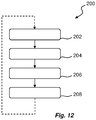
- the method 200 comprises a first step 202 of feeding an unfolded flap 53a to pass a convex portion 142 of a disc-like member 140 in order to cause folding of the flap 53a.
- the convex portion 142 is preferably stationary during this step, although a rotational movement may also be considered.
- the method 200 performs a step 204 of rotating the disc-like member 140 such that a recessed portion 144 of the disc-like member 140 is arranged in a position facing a feeder 16.
- the method 200 performs a step 206 of rotating the disc-like member 140 such that the convex portion 142 will accelerate and reach the rear flaps 53b from behind. Upon further rotation of the disc-like member 140, the rear flap 53b will be folded.
- step 206 the method 200 will perform a step 208 of continued rotation of the disc-like member 140 for returning the disc-like member 140 to its idle position where the convex portion 142 is ready to engage with a passing front flap 53a.
- the method 200 is repeated in order to perform flap folding of a sequence of passing articles, preferably cardboard cases 60 as described previously.
Abstract
Description
- The invention relates to a cardboard packer, in particular to a cardboard packer for producing boxes, trays, and/or wrap-around units for a plurality of carton packages. The invention also relates to a folding unit for such cardboard packer, as well as to a folding method for a cardboard packer.
- Individual packaging containers, such as liquid food packaging containers, are typically produced from a carton-based material and filled using a high-speed filling machine. When the filled, formed, and sealed packaging containers are unloaded from the filling machine they are transferred to a cardboard packer in which a predetermined number of packaging containers are stacked in a packing pattern and placed in a case made from a cardboard blank.
- The cardboard case, which may be in the form of a box, a tray, or a wrap-around unit is produced by folding the blank; the blank may e.g. be formed by cutting a corrugated cardboard sheet or the like into a predetermined shape. The shape of the blank varies in accordance with the dimension and number of packaging containers to be placed in the case, and the manner of packaging. In the case of a tray blank, the blank sheet has a shape to cover two opposing side surfaces of a group of packaging containers which have been stacked on the blank sheet in a predetermined packing pattern. In the case of a wrap-around blank, the blank sheet has a shape to wholly cover a group of packaging containers which have been stacked on the blank sheet in a predetermined packing pattern. For various types of cardboard cases, the cardboard blank comprises flaps which need to be folded in order to form the desired shape of the case.
- An example of flap folding is described in
CA2771449 by the same applicant. According to this disclosure, L-shaped flap folders are activated by a pneumatic actuator pushing the cardboard case upwards. During flap folding, the cardboard case is stationary in the machine feed direction. - Due to different customer requirements in terms of sizes and dimensions of the cardboard cases, the above-described prior art flap folders need to be adjusted accordingly if a producer decides to change the physical dimensions of the cases to be manufactured.
- There is thus a need for an improved cardboard packer, and in particular for an improved flap folding unit, which can be used for different dimensions of the cardboard case.
- It is an object of the invention to at least partly overcome one or more of the above-identified limitations of the prior art. In particular, it is an object to provide a cardboard packer which allows for accurate folding of the flaps of the cardboard case, independently of the dimensions of the cardboard case.
- According to a first aspect, a flap folding unit is provided. The flap folding unit comprises at least one flap folding device having a disc-like member being configured to be arranged in a first position to urge passing front flaps of an associated cardboard case to fold, and in a second position to allow unfolded rear flaps of the associated cardboard case to pass the disc-like member.
- The disc-like member may comprise a convex portion and a recessed portion. Due to different geometries along a full revolution, engagement of the disc-like member with passing flaps can be controlled.
- The convex portion may be a section having a circular periphery.
- The disc-like member may be configured to rotate from its second position to its first position, thereby urging rear flaps of the associated cardboard case to fold.
- The disc-like member may be connected to a link arm. The link arm may extend substantially parallel with a cardboard case feeder. In an embodiment, the link arm is pivotally supported.
- The flap folding device may comprise two spaced apart flap folding devices. Hence, each flap folding device can cause folding of flaps on a specific side of the cardboard case.
- The flap folding devices may consequently be arranged on opposite sides of a feeder (60).
- Both flap folding devices may be driven by a common electrical motor. Further, a controller may be provided and configured to control rotation of the disc-like member.
- According to a second aspect, a cardboard packer is provided. The cardboard packer comprises a flap folding unit according to the first aspect.
- According to a third aspect, a method for performing flap folding is provided. The method comprises feeding an unfolded flap to pass a convex portion of a disc-like member thereby urging the flap to fold. Once the flap has passed the convex portion, the method performs rotation of the disc-like member such that a recessed portion of the disc-like member is facing a transport area of one or more flaps, and once an unfolded rear flap has passed the recessed portion, the method performs rotation of the disc-like member such that the convex portion will accelerate and reach the rear flap from behind, causing the rear flap to fold.
- The method may further perform final rotation of the disc-like member for returning the disc-like member to its idle position where the convex portion is ready to engage with a passing front flap.
- According to a fourth aspect, a non-transitory computer-readable storage medium is provided, storing one or more programs configured for execution by one or more processors. The one or more programs comprises instructions for controlling the position of a disc-like member such that a passing unfolded flap engages with a convex portion of the disc-like member thereby urging the flap to fold, and once the flap has passed the convex portion, for controlling rotation of the disc-like member such that a recessed portion of the disc-like member is facing a transport area of one or more flaps, and once an unfolded rear flap has passed the recessed portion, for controlling rotation of the disc-like member such that the convex portion will accelerate and reach the rear flap from behind, causing the rear flap to fold.
- Still other objectives, features, aspects and advantages of the invention will appear from the following detailed description as well as from the drawings.
- Embodiments of the invention will now be described, by way of example, with reference to the accompanying schematic drawings, in which
-
Fig. 1 is a schematic view of a cardboard packer according to an embodiment; -
Fig. 2 is an isometric view of a cardboard package produced by a cardboard packer; -
Fig. 3 is a top view of a blank to be fed to a cardboard packer, and to be used to form a cardboard case; -
Figs. 4a-d are schematic side views of how a cardboard blank is transformed to a cardboard case by means of a cardboard packer according to an embodiment; -
Fig. 5 is a top view of a parts of a cardboard packer, having a flap folding unit according to an embodiment; -
Figs. 6-10 are schematic top views of the flap folding process according to an embodiment; -
Fig. 11 is an isometric view of a flap folding unit according to an embodiment; and -
Fig. 12 is a schematic view of a method for a cardboard packer. - With reference to
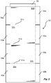
Fig. 1 acardboard packer 10 is illustrated. Thecardboard packer 10 is configured to transform a cardboard blank to a cardboard package, as will be explained in the following. - The
cardboard packer 10 is fed with ablanks magazine 12. Themagazine 12 contains a number of separate blanks, stacked on top of each other in themagazine 12. Thecardboard packer 10 is also receiving a flow ofindividual packages 20, such ascarton packages 20 filled with a liquid food product or other suitable content, may it be in solid form or in liquid form. - The
cardboard packer 10 comprises ablank picker 14 which is configured to access themagazine 12 and to grip one blank 50 at the time, and to move the blank 50 from themagazine 12 to ablank feeder 16. Theblank feeder 16 is preferably configured to perform initial folding and forming of the blank towards thefinal cardboard package 30. Hence, thefeeder 16 is in some way configured to also receive thecarton packages 20, and to arrange thecarton packages 20 within thecardboard package 30. - A
flap folding unit 100 is provided along the transport path of thefeeder 16. As is clear fromFig. 1 , thecardboard packer 10 also includes acontrol unit 40 for controlling the operation of theflap folding unit 100, at least. - In
Fig. 2 acardboard package 30 is shown. Thecardboard package 30 is representing only one example of how a blank 50 can be formed into an enclosing structure for a plurality of individual packaging containers 20 (in this example 12 pieces). - In
Fig. 3 an example of acardboard blank 50 is shown. Thecardboard blank 50 is in the form of planar sheet, comprising a plurality of features to assist in forming the blank 50 into a three-dimensional body. - A
first crease line 51a is arranged transverse to separate arear panel 52a from abottom panel 52b. Similarly, asecond crease line 51b is arranged in parallel, but spaced apart from thefirst crease line 51a to separate thebottom panel 52b from afront panel 52c. Athird crease line 51c is arranged in parallel, but spaced apart from the first andsecond crease lines 51a-b to separate thefront panel 52c from atop panel 52d. - The blank 50 is provided with a plurality of flaps 53-55. Front flaps 53a extend laterally on each side of the
front panel 52c, whilerear flaps 53b extend laterally on each side of therear panel 52a. Bottom flaps 54a extend laterally on each side of thebottom panel 52b, whiletop flaps 54b extend laterally on each side of thetop panel 52d. Yet further, aclosing flap 55 is extending longitudinally from thetop panel 52d. - Now turning to
Figs. 4a-d , the process of forming a cardboard case is schematically illustrated. It should be noted that the described process is configured forblanks 50 of the type shown inFig. 3 ; shouldother blanks 50 be used, the process of forming a cardboard case may be adjusted. - In
Fig. 4a a plurality ofpackaging containers 20 are positioned onto thebottom panel 52b of the blank 50. Therear panel 52a and thefront panel 52c are folded approximately 90° from thebottom panel 52b. - In
Fig. 4b it is shown how thefront flaps 53a and therear flaps 53b have been folded inwards, towards thepackaging containers 20. - In
Fig. 4c , thetop panel 52d is folded downwards and towards the upper portion of thepackaging container 20. - In a last step, shown in
Fig. 4d , thetop flaps 54b are folded downwards while the bottom flaps 54a are folded upwards. Also, theclosing flap 55 is folded downwards. Optionally, thetop flaps 54b and the bottom flaps 54a are sealed to the front andrear flaps 53a-b, and theclosing flap 55 may be sealed to therear panel 52a. - Now, with reference to
Fig. 5 and onwards, details of theflap folding unit 100 will be given. Theflap folding unit 100 is configured to fold the front andrear flaps 53a-b of the blank 50, although it should be understood that theflap folding unit 100 could be used to fold any kind of suitable flap. - In
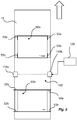
Fig. 5 a schematic top view of thefeeder 16 is shown; the transport direction is indicated by the block arrow. Thefeeder 16 receives a flow of blanks 50 (as shown inFig. 1 ), and theblanks 50 are transformed into closedcardboard cases 60 during their transport along thefeeder 16. Hence, as indicated inFig. 5 a leading soon-to-be-formed cardboard case 60a is followed by a trailing soon-to-be-formed cardboard case 60b. - The
flap folding unit 100 is arranged along the transport path of thefeeder 16. In particular, theflap folding unit 100 comprises a firstflap folding device 110a on a first side of thefeeder 16, and a secondflap folding device 110b on the opposite side of thefeeder 16. - As can be seen in
Fig. 5 , the trailingcardboard case 60b is arranged with its front andrear flaps 53a-b still unfolded. However, once the cardboard case passes theflap folding unit 100, the front andrear flaps 53a-b will be folded due to the action of theflap folding unit 100. This is illustrated for the leadingcardboard case 60a. - As will be explained in the following, operation of the
flap folding unit 100 is controlled by means of acontroller 120. Thecontroller 120 forms part of theflap folding unit 100, or is connected thereto, in order to transmit control signals to driving components of theflap folding unit 100. - The
flap folding unit 100 is shown inFig. 6 . Theflap folding unit 100 comprises a firstflap folding device 110a and a second flap folding device 110b.Theflap folding devices 110a-b are arranged on opposite lateral sides of thefeeder 16, such that the firstflap folding device 110a will act on one side of thecardboard case 60, while the secondflap folding device 110b will act on the opposite side of thecardboard case 60. - As can be seen in
Fig. 6 , theflap folding devices 110a-b are identical, at least with regards to how they act on thecardboard case 60 and engage with therespective flaps 53a-b. - As will be further explained with regards to
Fig. 11 , theflap folding unit 100 comprises a drive means 130, preferably in the form of an electrical motor. Theelectrical motor 130 is powered by a power supply (not shown), and theelectrical motor 130 is connected to thecontroller 120 to receive control signals. - Again referring to
Fig. 6 , aflap folding device 110a-b comprises a disc-like member 140. Reference numerals are only inserted for the leftflap folding device 110a, although the otherflap folding device 110b comprises the same components. - The disc-
like member 140 has aconvex portion 142 and a recessedportion 144. Theconvex portion 142 is preferably a section of a circular periphery, while theconcave portion 144 is a cut-out from the circular periphery. As shown inFig. 6 , theconvex portion 142 extends slightly less than 180°. However, other extensions of theconvex portion 142 are also possible. The recessedportion 144 has a curved shape, such that the disc-like member 140 exhibits a claw shape. - The disc-
like member 140 is rotationally supported, and driven by theelectrical motor 130. The rotational axis of the disc-like member 140 is preferably coinciding with the center point of the disc-like member 140; otherwise theconvex portion 142 would move in an eccentric motion, possibly not supporting theflap 53a after it has been folded. - At the position of the rotational axis R, the disc-
like member 140 is rotationally connected to a pivotinglever 150, which in turn is connected to alink arm 152. Thelink arm 152 extends substantially in parallel with thefeeder 16, i.e. parallel to the direction by which thecardboard case 60 is transported. However, as the disc-like member 140 rotates by activation of theelectrical motor 130, the pivotinglever 150 will pivot thereby causing thelink arm 152 to pivot as well. The direction of thelink arm 152 will thereby deviate slightly from a strict parallel alignment with the longitudinal axis of thefeeder 16. As can be seen inFig. 6 , thelink arm 152 is pivotally supported by means at a pivot joint 154 arranged off-center the longitudinal axis of thelink arm 152. - As the
cardboard case 60 is approaching theflap folding unit 100, thefront flaps 53a (still being unfolded) will come into contact with theconvex portion 142 of the disc-like member 140. During this motion of thecardboard case 60, the disc-like member 140 is kept stationary. Due to the convex shape of the disc-like member 140, i.e. theconvex portion 142 is located such that theflaps 53a will engage with it, theflaps 53a will be urged to fold as thecardboard case 60 moves forward. - A subsequent position of the
cardboard case 60 is shown inFig. 7 . In this position thefeeder 16 has moved thecardboard case 60 to a position where thefront flaps 53a have been folded entirely by thecurved portion 142 of the disc-like member 140. So far, the disc-like member 140 has not rotated. - Once the
cardboard case 60 has moved to a position where thefront flaps 53a have been fully folded, i.e. immediately after the position shown inFig. 7 , the disc-like member 140 is kept stationary in order to support and guide the loaded packaging containers to secure that they do not move out from thecardboard case 60. When therear flaps 53b are approaching the disc-like members 140, the disc-like members 140 are rapidly rotated such that therear flap 53b can pass the recessedportion 144 of the disc-like member 140. Hence, the rotation of each disc-like member 140 is synchronized with the motion of therear flaps 53b, which also means that it will be possible to adjust the motion of theflap folding devices 110a-b for different sizes of thecardboard case 60. This is shown inFig. 8 . The disc-like member 140 has rotated slightly more than 90° from its position shown inFig. 7 . - The
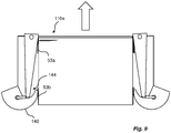
flap folding device 110a is programmed, preferably by means of thecontroller 120, to perform a fast rotation of the disc-like member 140 from the position shown inFig. 8 , in a direction indicated inFig. 8 . As thecardboard case 60 moves forward, theconvex portion 142 will accelerate and reach therear flaps 53b from behind as is shown inFig. 9 . As theconvex portion 142 moves faster than thecardboard case 60, therear flaps 53b will be urged to fold in a forward direction as thecardboard case 60 moves forward, and as the disc-like member 140 pushes theflaps 53b in the forward direction at a speed greater than the speed of thecardboard case 60. When the disc-like member 140 reaches its initial position (i.e. the angular position shown inFig. 6 ), therear flaps 53b are fully folded and the rotational movement of the disc-like member 140 is stopped. - The same motion sequence is repeated for
subsequent cardboard cases 60 being transported by thefeeder 16. - The
link arm 152 will assist in keeping theflaps 53a-b folded as they pass the disc-like member 140. As thefront flaps 53a have been folded, they will be in contact with an inner side of therespective link arm 152 in order to assist in maintaining the folded position of thefront flaps 53a. However, folding of therear flaps 53b will also be assisted due to the shape of thelink arm 152. In particular, with reference toFig. 10 there will be a leading cardboard case in front of thecardboard case 60. As thecardboard case 60 is stationary on thefeeder 16 such that packaging containers are allowed to be loaded onto the yet unfoldedcardboard case 60, the leading cardboard case will be positioned such that thelink arm 152 keeps therear flaps 53b of the leading cardboard in their folded position. Of course, other means may be implemented for keeping the flaps in their folded position, such as linear motors that generate a pushing movement in the direction transverse to the direction by which thecardboard case 60 is transported, to push and keep the flaps against thecase 60. Thus, thelink arms 152 represents one of several embodiments for keeping the flaps in place. - Now turning to
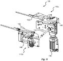
Fig. 11 , an embodiment of aflap folding unit 100 is shown separate from the feeder etc. Theflap folding unit 100 has a firstflap folding device 110a and a secondflap folding device 110b. Each flap folding device has a disc-like member 140, as described earlier with reference toFigs. 6-10 . The firstflap folding device 110a is driven by means of anelectrical motor 130. However, the firstflap folding device 110a is connected to the secondflap folding device 110b by means of arotational shaft 132, such that rotation of the disc-like member 140 of the firstflap folding device 110a is also transmitted to the secondflap folding device 110b, thereby causing the disc-like member 140 of the secondflap folding device 110b to rotate as well. For the transmission, worm gears or similar can be used. Instead of a mechanical transmission, it would also be possible to use separate motors for eachflap folding device 110a-b. - Now turning to
Fig. 12 , amethod 200 for flap folding is schematically shown. Themethod 200 comprises afirst step 202 of feeding an unfoldedflap 53a to pass aconvex portion 142 of a disc-like member 140 in order to cause folding of theflap 53a. Theconvex portion 142 is preferably stationary during this step, although a rotational movement may also be considered. As soon as the foldedflap 53a is transported beyond theconvex portion 142, themethod 200 performs astep 204 of rotating the disc-like member 140 such that a recessedportion 144 of the disc-like member 140 is arranged in a position facing afeeder 16. As an unfoldedrear flap 53b is approaching, it will be allowed to pass the disc-like member 140 by no contact due to the provision of the recessedportion 144. As soon as the unfoldedrear flap 53b has passed the recessedportion 144, themethod 200 performs astep 206 of rotating the disc-like member 140 such that theconvex portion 142 will accelerate and reach therear flaps 53b from behind. Upon further rotation of the disc-like member 140, therear flap 53b will be folded. - After performing
step 206, themethod 200 will perform astep 208 of continued rotation of the disc-like member 140 for returning the disc-like member 140 to its idle position where theconvex portion 142 is ready to engage with a passingfront flap 53a. - The
method 200 is repeated in order to perform flap folding of a sequence of passing articles, preferablycardboard cases 60 as described previously. - From the description above follows that, although various embodiments of the invention have been described and shown, the invention is not restricted thereto, but may also be embodied in other ways within the scope of the subject-matter defined in the following claims.
Claims (15)
- A flap folding unit (100), comprising at least one flap folding device (110a-b) having a disc-like member (140) being configured to be arranged in a first position to urge passing front flaps (53a) of an associated cardboard case (60) to fold, and in a second position to allow unfolded rear flaps (53b) of the associated cardboard case (60) to pass the disc-like member (140).
- The flap folding unit (100) according to claim 1, wherein the disc-like member (140) comprises a convex portion (142) and a recessed portion (144).
- The flap folding unit (100) according to claim 2, wherein the convex portion (142) is a section having a circular periphery.
- The flap folding unit (100) according to any of the preceding claims, wherein the disc-like member (140) is configured to rotate from its second position to its first position, thereby urging rear flaps (53b) of the associated cardboard case (60) to fold.
- The flap folding unit (100) according to any of the preceding claims, wherein the disc-like member (140) is connected to a link arm (152).
- The flap folding unit (100) according to claim 5, wherein the link arm (152) extends substantially parallel with a cardboard case feeder (16).
- The flap folding unit (100) according to claim 5 or 6, wherein the link arm (152) is pivotally supported.
- The flap folding unit (100) according to any of the preceding claims, comprising two spaced apart flap folding devices (110a-b).
- The flap folding unit (100) according to claim 8, wherein the flap folding devices (110a-b) are arranged on opposite sides of a feeder (60).
- The flap folding unit (100) according to claim 8 or 9, wherein both flap folding devices (110a-b) are driven by a common electrical motor (130).
- The flap folding unit (100) according to any of the preceding claims, further comprising a controller (120) being configured to control rotation of the disc-like member (140).
- A cardboard packer (10), comprising a flap folding unit (100) according to any of the preceding claims.
- A method for performing flap folding, comprising
feeding (202) an unfolded flap (53a) to pass a convex portion (142) of a disc-like member (140) thereby urging the flap (53a) to fold,
once the flap (53a) has passed the convex portion (142), rotating (204) the disc-like member (140) such that a recessed portion (144) of the disc-like member (140) is facing a transport area of one or more flaps, and
once an unfolded rear flap (53b) has passed the recessed portion 144, rotating (206) the disc-like member (140) such that the convex portion (142) will accelerate and reach the rear flap (53b) from behind, causing the rear flap (53b) to fold. - The method according to claim 13, further comprising final rotation (208) of the disc-like member (140) for returning the disc-like member (140) to its idle position where the convex portion (142) is ready to engage with a passing front flap (53a).
- A non-transitory computer-readable storage medium, storing one or more programs configured for execution by one or more processors, the one or more programs comprising instructions for:controlling a disc-like member (140) such that a passing unfolded flap (53a) engages with a convex portion (142) of the disc-like member (140) thereby urging the flap (53a) to fold,once the flap (53a) has passed the convex portion (142), controlling rotating (204) the disc-like member (140) such that a recessed portion (144) of the disc-like member (140) is facing a transport area of one or more flaps, andonce an unfolded rear flap (53b) has passed the recessed portion 144, controlling rotating (206) the disc-like member (140) such that the convex portion (142) will accelerate and reach the rear flap (53b) from behind, causing the rear flap (53b) to fold.
Applications Claiming Priority (1)
| Application Number | Priority Date | Filing Date | Title |
|---|---|---|---|
| EP19218136 | 2019-12-19 |
Publications (2)
| Publication Number | Publication Date |
|---|---|
| EP3838768A1 true EP3838768A1 (en) | 2021-06-23 |
| EP3838768B1 EP3838768B1 (en) | 2022-11-30 |
Family
ID=69410935
Family Applications (1)
| Application Number | Title | Priority Date | Filing Date |
|---|---|---|---|
| EP20215563.6A Active EP3838768B1 (en) | 2019-12-19 | 2020-12-18 | A carboard packer, and a folding unit for a cardboard packer |
Country Status (4)
| Country | Link |
|---|---|
| US (1) | US20230025633A1 (en) |
| EP (1) | EP3838768B1 (en) |
| CN (1) | CN114761327B (en) |
| WO (1) | WO2021123263A1 (en) |
Citations (7)
| Publication number | Priority date | Publication date | Assignee | Title |
|---|---|---|---|---|
| US3021768A (en) * | 1956-12-24 | 1962-02-20 | American Mach & Foundry | Apparatus for wrapping |
| US4987727A (en) * | 1988-10-20 | 1991-01-29 | Mcclusky Machinery Sales & Service | Apparatus for packaging citrus fruit |
| US5148654A (en) * | 1990-06-05 | 1992-09-22 | Kisters Maschinenbau Gmbh | Packaging system |
| CA2771449A1 (en) | 2009-08-17 | 2011-02-24 | Tetra Laval Holdings & Finance S.A. | Final folder for cardboard packer |
| DE102010015865A1 (en) * | 2010-03-09 | 2011-09-15 | Krones Ag | Apparatus and method for packaging articles |
| EP3015373A1 (en) * | 2014-10-28 | 2016-05-04 | Rama S.r.l. | Automatic closing group for lids of cardboard boxes formed by punching |
| US20190160774A1 (en) * | 2012-04-24 | 2019-05-30 | H. J. Paul Langen | Method and apparatus for forming containers |
Family Cites Families (13)
| Publication number | Priority date | Publication date | Assignee | Title |
|---|---|---|---|---|
| US2957395A (en) * | 1956-10-09 | 1960-10-25 | Louis A Meyer | Box forming machine |
| US3513757A (en) * | 1967-07-14 | 1970-05-26 | Owens Illinois Inc | Manufacture of open-topped trays |
| US6017298A (en) * | 1998-08-28 | 2000-01-25 | Ward Holding Company | Spiral folder |
| US6226965B1 (en) * | 1999-12-08 | 2001-05-08 | Belcor Industries Inc | Inline case sealing system |
| US6887191B2 (en) * | 2000-10-12 | 2005-05-03 | International Paper Company | Carton bottom forming method and apparatus |
| ES2189680B1 (en) * | 2001-12-05 | 2004-10-16 | Los Pinos Finca Agricola, S.L. | MOLD FOR FORMATION OF CARTON BOXES. |
| US8246527B2 (en) * | 2009-10-21 | 2012-08-21 | J&L Group International, Llc | Systems and methods for folding |
| US8529421B2 (en) * | 2010-01-19 | 2013-09-10 | Richard J. Fallas | Package flap folding method and apparatus |
| WO2014118629A2 (en) * | 2013-01-29 | 2014-08-07 | Neopost Technologies | Method and system for automatically forming packaging boxes |
| EP3187423B1 (en) * | 2015-12-31 | 2018-05-09 | Neopost Technologies | Folding unit for folding cardboard blanks, folding apparatus comprising such folding unit and method for folding cardboard |
| ITUA20163733A1 (en) * | 2016-05-24 | 2017-11-24 | F L Auto Srl | BENDING STATION FOR BENDING A PACKING BOX AND MACHINE FOR PACKING AN ARTICLE INTO A CARTON BOX OBTAINED FROM A PACKING CARD |
| JP7199686B2 (en) * | 2018-06-11 | 2023-01-06 | 株式会社イシダ | cartoning equipment |
| EP3674072A1 (en) * | 2018-12-30 | 2020-07-01 | Neopost Technologies | System and method for forming boxes from cardboard blanks |
-
2020
- 2020-12-18 WO PCT/EP2020/087163 patent/WO2021123263A1/en active Application Filing
- 2020-12-18 CN CN202080084947.9A patent/CN114761327B/en active Active
- 2020-12-18 US US17/786,257 patent/US20230025633A1/en active Pending
- 2020-12-18 EP EP20215563.6A patent/EP3838768B1/en active Active
Patent Citations (7)
| Publication number | Priority date | Publication date | Assignee | Title |
|---|---|---|---|---|
| US3021768A (en) * | 1956-12-24 | 1962-02-20 | American Mach & Foundry | Apparatus for wrapping |
| US4987727A (en) * | 1988-10-20 | 1991-01-29 | Mcclusky Machinery Sales & Service | Apparatus for packaging citrus fruit |
| US5148654A (en) * | 1990-06-05 | 1992-09-22 | Kisters Maschinenbau Gmbh | Packaging system |
| CA2771449A1 (en) | 2009-08-17 | 2011-02-24 | Tetra Laval Holdings & Finance S.A. | Final folder for cardboard packer |
| DE102010015865A1 (en) * | 2010-03-09 | 2011-09-15 | Krones Ag | Apparatus and method for packaging articles |
| US20190160774A1 (en) * | 2012-04-24 | 2019-05-30 | H. J. Paul Langen | Method and apparatus for forming containers |
| EP3015373A1 (en) * | 2014-10-28 | 2016-05-04 | Rama S.r.l. | Automatic closing group for lids of cardboard boxes formed by punching |
Also Published As
| Publication number | Publication date |
|---|---|
| US20230025633A1 (en) | 2023-01-26 |
| CN114761327A (en) | 2022-07-15 |
| WO2021123263A1 (en) | 2021-06-24 |
| CN114761327B (en) | 2024-05-07 |
| EP3838768B1 (en) | 2022-11-30 |
Similar Documents
| Publication | Publication Date | Title |
|---|---|---|
| EP3015373B1 (en) | Automatic closing group for lids of cardboard boxes formed by punching | |
| EP1359092B1 (en) | Method and device for turning over stacks of products on a cartoning machine | |
| US3461642A (en) | Method and machine for forming and sealing a carton | |
| US3716962A (en) | Carton flap folding mechanism | |
| US7510517B2 (en) | Case erector apparatus | |
| US2890560A (en) | Case flap opener | |
| EP1826126B1 (en) | Folding unit for producing sealed packages of pourable food products | |
| WO2006023758A2 (en) | Wrap around carton packaging machine | |
| US5561968A (en) | Automated cartoner | |
| US11059252B2 (en) | Machine for forming a container from a blank | |
| US8419602B1 (en) | Cartoner for cartons having concave sides | |
| US3504478A (en) | Auxiliary end flap sealer for cartoning machine | |
| US2909874A (en) | Packaging machine | |
| US7475525B2 (en) | Method and device for producing packs from at least two partial packs | |
| JPS6154646B2 (en) | ||
| EP3838768B1 (en) | A carboard packer, and a folding unit for a cardboard packer | |
| US3844088A (en) | Packaging and blank handling systems | |
| US11820542B2 (en) | Method and apparatus for reconfiguring containers | |
| US2441410A (en) | Method and apparatus for closing cartons | |
| US3405611A (en) | Article handling method and apparatus | |
| US4012999A (en) | Apparatus for forming trays | |
| BE1026698B1 (en) | Packaging machine feeding, separating and folding mechanisms | |
| EP1757521B1 (en) | A machine for packing products in cases | |
| US2935832A (en) | Box making machine | |
| US3452514A (en) | Packaging apparatus |
Legal Events
| Date | Code | Title | Description |
|---|---|---|---|
| PUAI | Public reference made under article 153(3) epc to a published international application that has entered the european phase |
Free format text: ORIGINAL CODE: 0009012 |
|
| STAA | Information on the status of an ep patent application or granted ep patent |
Free format text: STATUS: THE APPLICATION HAS BEEN PUBLISHED |
|
| AK | Designated contracting states |
Kind code of ref document: A1 Designated state(s): AL AT BE BG CH CY CZ DE DK EE ES FI FR GB GR HR HU IE IS IT LI LT LU LV MC MK MT NL NO PL PT RO RS SE SI SK SM TR |
|
| STAA | Information on the status of an ep patent application or granted ep patent |
Free format text: STATUS: REQUEST FOR EXAMINATION WAS MADE |
|
| 17P | Request for examination filed |
Effective date: 20211223 |
|
| RBV | Designated contracting states (corrected) |
Designated state(s): AL AT BE BG CH CY CZ DE DK EE ES FI FR GB GR HR HU IE IS IT LI LT LU LV MC MK MT NL NO PL PT RO RS SE SI SK SM TR |
|
| RIC1 | Information provided on ipc code assigned before grant |
Ipc: B65B 43/14 20060101ALI20220628BHEP Ipc: B65B 49/12 20060101ALI20220628BHEP Ipc: B65B 49/08 20060101ALI20220628BHEP Ipc: B65B 43/10 20060101ALI20220628BHEP Ipc: B65B 11/04 20060101ALI20220628BHEP Ipc: B65B 43/26 20060101ALI20220628BHEP Ipc: B31B 50/00 20170101ALI20220628BHEP Ipc: B65B 7/20 20060101AFI20220628BHEP |
|
| GRAP | Despatch of communication of intention to grant a patent |
Free format text: ORIGINAL CODE: EPIDOSNIGR1 |
|
| STAA | Information on the status of an ep patent application or granted ep patent |
Free format text: STATUS: GRANT OF PATENT IS INTENDED |
|
| INTG | Intention to grant announced |
Effective date: 20220811 |
|
| GRAS | Grant fee paid |
Free format text: ORIGINAL CODE: EPIDOSNIGR3 |
|
| GRAA | (expected) grant |
Free format text: ORIGINAL CODE: 0009210 |
|
| STAA | Information on the status of an ep patent application or granted ep patent |
Free format text: STATUS: THE PATENT HAS BEEN GRANTED |
|
| AK | Designated contracting states |
Kind code of ref document: B1 Designated state(s): AL AT BE BG CH CY CZ DE DK EE ES FI FR GB GR HR HU IE IS IT LI LT LU LV MC MK MT NL NO PL PT RO RS SE SI SK SM TR |
|
| REG | Reference to a national code |
Ref country code: CH Ref legal event code: EP Ref country code: GB Ref legal event code: FG4D |
|
| REG | Reference to a national code |
Ref country code: AT Ref legal event code: REF Ref document number: 1534519 Country of ref document: AT Kind code of ref document: T Effective date: 20221215 Ref country code: DE Ref legal event code: R096 Ref document number: 602020006618 Country of ref document: DE |
|
| REG | Reference to a national code |
Ref country code: IE Ref legal event code: FG4D |
|
| REG | Reference to a national code |
Ref country code: LT Ref legal event code: MG9D |
|
| REG | Reference to a national code |
Ref country code: NL Ref legal event code: MP Effective date: 20221130 |
|
| PG25 | Lapsed in a contracting state [announced via postgrant information from national office to epo] |
Ref country code: SE Free format text: LAPSE BECAUSE OF FAILURE TO SUBMIT A TRANSLATION OF THE DESCRIPTION OR TO PAY THE FEE WITHIN THE PRESCRIBED TIME-LIMIT Effective date: 20221130 Ref country code: PT Free format text: LAPSE BECAUSE OF FAILURE TO SUBMIT A TRANSLATION OF THE DESCRIPTION OR TO PAY THE FEE WITHIN THE PRESCRIBED TIME-LIMIT Effective date: 20230331 Ref country code: NO Free format text: LAPSE BECAUSE OF FAILURE TO SUBMIT A TRANSLATION OF THE DESCRIPTION OR TO PAY THE FEE WITHIN THE PRESCRIBED TIME-LIMIT Effective date: 20230228 Ref country code: LT Free format text: LAPSE BECAUSE OF FAILURE TO SUBMIT A TRANSLATION OF THE DESCRIPTION OR TO PAY THE FEE WITHIN THE PRESCRIBED TIME-LIMIT Effective date: 20221130 Ref country code: FI Free format text: LAPSE BECAUSE OF FAILURE TO SUBMIT A TRANSLATION OF THE DESCRIPTION OR TO PAY THE FEE WITHIN THE PRESCRIBED TIME-LIMIT Effective date: 20221130 Ref country code: ES Free format text: LAPSE BECAUSE OF FAILURE TO SUBMIT A TRANSLATION OF THE DESCRIPTION OR TO PAY THE FEE WITHIN THE PRESCRIBED TIME-LIMIT Effective date: 20221130 |
|
| REG | Reference to a national code |
Ref country code: AT Ref legal event code: MK05 Ref document number: 1534519 Country of ref document: AT Kind code of ref document: T Effective date: 20221130 |
|
| PG25 | Lapsed in a contracting state [announced via postgrant information from national office to epo] |
Ref country code: RS Free format text: LAPSE BECAUSE OF FAILURE TO SUBMIT A TRANSLATION OF THE DESCRIPTION OR TO PAY THE FEE WITHIN THE PRESCRIBED TIME-LIMIT Effective date: 20221130 Ref country code: PL Free format text: LAPSE BECAUSE OF FAILURE TO SUBMIT A TRANSLATION OF THE DESCRIPTION OR TO PAY THE FEE WITHIN THE PRESCRIBED TIME-LIMIT Effective date: 20221130 Ref country code: LV Free format text: LAPSE BECAUSE OF FAILURE TO SUBMIT A TRANSLATION OF THE DESCRIPTION OR TO PAY THE FEE WITHIN THE PRESCRIBED TIME-LIMIT Effective date: 20221130 Ref country code: IS Free format text: LAPSE BECAUSE OF FAILURE TO SUBMIT A TRANSLATION OF THE DESCRIPTION OR TO PAY THE FEE WITHIN THE PRESCRIBED TIME-LIMIT Effective date: 20230330 Ref country code: HR Free format text: LAPSE BECAUSE OF FAILURE TO SUBMIT A TRANSLATION OF THE DESCRIPTION OR TO PAY THE FEE WITHIN THE PRESCRIBED TIME-LIMIT Effective date: 20221130 Ref country code: GR Free format text: LAPSE BECAUSE OF FAILURE TO SUBMIT A TRANSLATION OF THE DESCRIPTION OR TO PAY THE FEE WITHIN THE PRESCRIBED TIME-LIMIT Effective date: 20230301 |
|
| PGFP | Annual fee paid to national office [announced via postgrant information from national office to epo] |
Ref country code: DE Payment date: 20221227 Year of fee payment: 3 |
|
| P01 | Opt-out of the competence of the unified patent court (upc) registered |
Effective date: 20230426 |
|
| PG25 | Lapsed in a contracting state [announced via postgrant information from national office to epo] |
Ref country code: NL Free format text: LAPSE BECAUSE OF FAILURE TO SUBMIT A TRANSLATION OF THE DESCRIPTION OR TO PAY THE FEE WITHIN THE PRESCRIBED TIME-LIMIT Effective date: 20221130 |
|
| PG25 | Lapsed in a contracting state [announced via postgrant information from national office to epo] |
Ref country code: SM Free format text: LAPSE BECAUSE OF FAILURE TO SUBMIT A TRANSLATION OF THE DESCRIPTION OR TO PAY THE FEE WITHIN THE PRESCRIBED TIME-LIMIT Effective date: 20221130 Ref country code: RO Free format text: LAPSE BECAUSE OF FAILURE TO SUBMIT A TRANSLATION OF THE DESCRIPTION OR TO PAY THE FEE WITHIN THE PRESCRIBED TIME-LIMIT Effective date: 20221130 Ref country code: IT Free format text: LAPSE BECAUSE OF NON-PAYMENT OF DUE FEES Effective date: 20221218 Ref country code: EE Free format text: LAPSE BECAUSE OF FAILURE TO SUBMIT A TRANSLATION OF THE DESCRIPTION OR TO PAY THE FEE WITHIN THE PRESCRIBED TIME-LIMIT Effective date: 20221130 Ref country code: DK Free format text: LAPSE BECAUSE OF FAILURE TO SUBMIT A TRANSLATION OF THE DESCRIPTION OR TO PAY THE FEE WITHIN THE PRESCRIBED TIME-LIMIT Effective date: 20221130 Ref country code: CZ Free format text: LAPSE BECAUSE OF FAILURE TO SUBMIT A TRANSLATION OF THE DESCRIPTION OR TO PAY THE FEE WITHIN THE PRESCRIBED TIME-LIMIT Effective date: 20221130 Ref country code: AT Free format text: LAPSE BECAUSE OF FAILURE TO SUBMIT A TRANSLATION OF THE DESCRIPTION OR TO PAY THE FEE WITHIN THE PRESCRIBED TIME-LIMIT Effective date: 20221130 |
|
| REG | Reference to a national code |
Ref country code: BE Ref legal event code: MM Effective date: 20221231 |
|
| PG25 | Lapsed in a contracting state [announced via postgrant information from national office to epo] |
Ref country code: SK Free format text: LAPSE BECAUSE OF FAILURE TO SUBMIT A TRANSLATION OF THE DESCRIPTION OR TO PAY THE FEE WITHIN THE PRESCRIBED TIME-LIMIT Effective date: 20221130 Ref country code: LU Free format text: LAPSE BECAUSE OF NON-PAYMENT OF DUE FEES Effective date: 20221218 Ref country code: AL Free format text: LAPSE BECAUSE OF FAILURE TO SUBMIT A TRANSLATION OF THE DESCRIPTION OR TO PAY THE FEE WITHIN THE PRESCRIBED TIME-LIMIT Effective date: 20221130 |
|
| REG | Reference to a national code |
Ref country code: DE Ref legal event code: R097 Ref document number: 602020006618 Country of ref document: DE |
|
| PLBE | No opposition filed within time limit |
Free format text: ORIGINAL CODE: 0009261 |
|
| STAA | Information on the status of an ep patent application or granted ep patent |
Free format text: STATUS: NO OPPOSITION FILED WITHIN TIME LIMIT |
|
| PG25 | Lapsed in a contracting state [announced via postgrant information from national office to epo] |
Ref country code: IT Free format text: LAPSE BECAUSE OF NON-PAYMENT OF DUE FEES Effective date: 20221218 Ref country code: IE Free format text: LAPSE BECAUSE OF NON-PAYMENT OF DUE FEES Effective date: 20221218 |
|
| PGFP | Annual fee paid to national office [announced via postgrant information from national office to epo] |
Ref country code: IT Payment date: 20221231 Year of fee payment: 3 |
|
| PGRI | Patent reinstated in contracting state [announced from national office to epo] |
Ref country code: IT Effective date: 20221231 |
|
| 26N | No opposition filed |
Effective date: 20230831 |
|
| PG25 | Lapsed in a contracting state [announced via postgrant information from national office to epo] |
Ref country code: SI Free format text: LAPSE BECAUSE OF FAILURE TO SUBMIT A TRANSLATION OF THE DESCRIPTION OR TO PAY THE FEE WITHIN THE PRESCRIBED TIME-LIMIT Effective date: 20221130 Ref country code: FR Free format text: LAPSE BECAUSE OF NON-PAYMENT OF DUE FEES Effective date: 20230130 Ref country code: BE Free format text: LAPSE BECAUSE OF NON-PAYMENT OF DUE FEES Effective date: 20221231 |
|
| PG25 | Lapsed in a contracting state [announced via postgrant information from national office to epo] |
Ref country code: CY Free format text: LAPSE BECAUSE OF FAILURE TO SUBMIT A TRANSLATION OF THE DESCRIPTION OR TO PAY THE FEE WITHIN THE PRESCRIBED TIME-LIMIT Effective date: 20221130 |
|
| PGFP | Annual fee paid to national office [announced via postgrant information from national office to epo] |
Ref country code: DE Payment date: 20231227 Year of fee payment: 4 |