EP3838428A1 - Cleaning tool for aerosol generation device - Google Patents
Cleaning tool for aerosol generation device Download PDFInfo
- Publication number
- EP3838428A1 EP3838428A1 EP19218019.8A EP19218019A EP3838428A1 EP 3838428 A1 EP3838428 A1 EP 3838428A1 EP 19218019 A EP19218019 A EP 19218019A EP 3838428 A1 EP3838428 A1 EP 3838428A1
- Authority
- EP
- European Patent Office
- Prior art keywords
- wipe
- cleaning
- cleaning tool
- heating chamber
- cleaning head
- Prior art date
- Legal status (The legal status is an assumption and is not a legal conclusion. Google has not performed a legal analysis and makes no representation as to the accuracy of the status listed.)
- Pending
Links
- 238000004140 cleaning Methods 0.000 title claims abstract description 188
- 239000000443 aerosol Substances 0.000 title claims abstract description 29
- 238000010438 heat treatment Methods 0.000 claims abstract description 93
- 230000000007 visual effect Effects 0.000 claims description 9
- 229920001971 elastomer Polymers 0.000 description 6
- 239000000806 elastomer Substances 0.000 description 4
- 241000208125 Nicotiana Species 0.000 description 3
- 235000002637 Nicotiana tabacum Nutrition 0.000 description 3
- 239000000758 substrate Substances 0.000 description 3
- 239000004676 acrylonitrile butadiene styrene Substances 0.000 description 2
- 238000000465 moulding Methods 0.000 description 2
- 239000005060 rubber Substances 0.000 description 2
- 229920001169 thermoplastic Polymers 0.000 description 2
- 239000004416 thermosoftening plastic Substances 0.000 description 2
- SNICXCGAKADSCV-JTQLQIEISA-N (-)-Nicotine Chemical compound CN1CCC[C@H]1C1=CC=CN=C1 SNICXCGAKADSCV-JTQLQIEISA-N 0.000 description 1
- 229920002943 EPDM rubber Polymers 0.000 description 1
- 239000004952 Polyamide Substances 0.000 description 1
- 239000004743 Polypropylene Substances 0.000 description 1
- 238000005452 bending Methods 0.000 description 1
- 238000010276 construction Methods 0.000 description 1
- 230000000694 effects Effects 0.000 description 1
- 239000010408 film Substances 0.000 description 1
- 239000002184 metal Substances 0.000 description 1
- 229960002715 nicotine Drugs 0.000 description 1
- SNICXCGAKADSCV-UHFFFAOYSA-N nicotine Natural products CN1CCCC1C1=CC=CN=C1 SNICXCGAKADSCV-UHFFFAOYSA-N 0.000 description 1
- 239000004033 plastic Substances 0.000 description 1
- 229920003023 plastic Polymers 0.000 description 1
- 229920002647 polyamide Polymers 0.000 description 1
- -1 polypropylene Polymers 0.000 description 1
- 229920001155 polypropylene Polymers 0.000 description 1
- 229920001296 polysiloxane Polymers 0.000 description 1
- 239000004814 polyurethane Substances 0.000 description 1
- 230000000284 resting effect Effects 0.000 description 1
- 239000007787 solid Substances 0.000 description 1
- 239000000126 substance Substances 0.000 description 1
- 229920002725 thermoplastic elastomer Polymers 0.000 description 1
- 239000010409 thin film Substances 0.000 description 1
Images


Classifications
-
- B08B1/145—
-
- A—HUMAN NECESSITIES
- A24—TOBACCO; CIGARS; CIGARETTES; SIMULATED SMOKING DEVICES; SMOKERS' REQUISITES
- A24F—SMOKERS' REQUISITES; MATCH BOXES; SIMULATED SMOKING DEVICES
- A24F40/00—Electrically operated smoking devices; Component parts thereof; Manufacture thereof; Maintenance or testing thereof; Charging means specially adapted therefor
- A24F40/85—Maintenance, e.g. cleaning
-
- B08B1/143—
-
- B—PERFORMING OPERATIONS; TRANSPORTING
- B08—CLEANING
- B08B—CLEANING IN GENERAL; PREVENTION OF FOULING IN GENERAL
- B08B9/00—Cleaning hollow articles by methods or apparatus specially adapted thereto
- B08B9/08—Cleaning containers, e.g. tanks
- B08B9/0804—Cleaning containers having tubular shape, e.g. casks, barrels, drums
- B08B9/0808—Cleaning containers having tubular shape, e.g. casks, barrels, drums by methods involving the use of tools, e.g. by brushes, scrapers
-
- A—HUMAN NECESSITIES
- A24—TOBACCO; CIGARS; CIGARETTES; SIMULATED SMOKING DEVICES; SMOKERS' REQUISITES
- A24F—SMOKERS' REQUISITES; MATCH BOXES; SIMULATED SMOKING DEVICES
- A24F40/00—Electrically operated smoking devices; Component parts thereof; Manufacture thereof; Maintenance or testing thereof; Charging means specially adapted therefor
- A24F40/20—Devices using solid inhalable precursors
Definitions
- Aerosol generation devices are designed to heat or burn an aerosol generation substrate, such as tobacco, to generate an aerosol. This typically leaves a residue in the aerosol generation device.
- a cleaning tool is used to remove the residue.
- Aerosol generating devices are increasingly popular for consumers as reduced risk nicotine delivery products, including e-cigarettes and tobacco vapour products. Such devices heat an aerosol generating substance in the form of a consumable within a heating chamber to produce a vapour to be inhaled by a user.
- Heating chambers generally comprise a heat conductive housing or shell defining an internal volume to hold a consumable and an opening through which the consumable may be received.
- a heater may be employed internally or externally to provide the increased temperature to the heating chamber.
- Most commonly such heating chambers are heated from the outside, with the conductive shell transferring the heat to the internal volume.
- One means to heat such heating chamber uses a thin film heater which conforms to a surface of a heating chamber to ensure efficient heating of a consumable received within the chamber.
- heating chambers need to be formed with a specific shape to accept a specific type of consumable.
- the internal surfaces of the heating chamber may also need to take a specific surface profile shape to hold the consumable and efficiently transfer heat to the consumable.
- One type of heating chamber has a closed end wall comprising multiple different surfaces. These surfaces may be arranged as an inner protrusion that protrudes from a central portion of the end wall into the heating chamber, and an annular ring surrounding the protrusion.
- This specific shape of the end wall can, for example, provide air gap for air circulation inside the consumable, assist with mounting the heating chamber within an aerosol generation device or assist in reducing the chance that a consumable becomes stuck to the end wall.
- heating tool for cleaning a heating chamber of an aerosol generation device, wherein the heating chamber comprises a side wall, an end wall, and protrusion that protrudes from a central portion of the end wall into the heating chamber.
- the present disclosure provides a cleaning tool for cleaning a heating chamber of an aerosol generation device, wherein the heating chamber comprises a side wall, an end wall, and protrusion that protrudes from a central portion of the end wall into the heating chamber, wherein the cleaning tool comprises a cleaning head, and the cleaning head comprises: an inner wipe configured for cleaning the protrusion; and an outer wipe configured for cleaning the end wall.
- the inner wipe and/or the outer wipe comprises a flexible wipe.
- the outer wipe comprises one or more rigid protrusions and the inner wipe comprises a flexible blade.
- the outer wipe further comprises a base portion attached to the one or more rigid protrusions, and the inner wipe is adapted to attach within the base portion.
- the outer wipe comprises one or more rigid protrusions and a flexible wipe.
- the outer wipe comprises a base portion attached to the one or more rigid protrusions, and the flexible wipe is adapted to attach within the base portion, the outer wipe and the one or more rigid protrusions being arranged such that the outer wipe can extend or bend to reach the end wall.
- the inner wipe comprises a flexible central blade configured for cleaning the protrusion, the central blade being shorter than the flexible wipe of the outer wipe.
- the central blade and the flexible wipe of the outer wipe are formed as a single flexible element.
- the cleaning tool is for a heating chamber comprising one or more ribs arranged along the side wall around an inner perimeter of the heating chamber, and the one or more rigid protrusions of the outer wipe are spaced to fit past the one or more ribs when the cleaning tool is appropriately aligned.
- the cleaning tool is for a heating chamber comprising one or more ribs arranged along the side wall around an inner perimeter of the heating chamber, and the one or more rigid protrusions of the outer wipe are arranged to rotate alongside the one or more ribs.
- the one or more rigid protrusions are barbs.
- the cleaning tool comprises a shaft, and arranged such that a user can hold one end of the shaft while using the cleaning head in the heating chamber, the shaft comprising a visual indicator arranged to indicate to the user when the cleaning head is near to the end wall.
- the cleaning tool further comprises a cap for covering the cleaning head, and a tether attaching the cap to the cleaning head.
- the cleaning tool comprises a cap for covering the cleaning head, wherein the cap is adapted to releasably attach to the cleaning head: in a first position at which the cleaning head is covered and in a second position at which the cleaning head is not covered and the cap is arranged as a handle or as a handle extension.
- Fig. 1A schematically illustrates an example of an aerosol generation device 100, in cross-section. This serves as an example of a type of aerosol generation device in which the subsequently described cleaning tool may be used.
- the aerosol generation device 100 comprises a heating chamber 110, a heater 120, control circuitry 130, an electrical power source 140, and a lid 150.
- the heating chamber 110 has a side wall 111, and end wall 112 and an open end 113 opposed to the end wall 112.
- the heating chamber may, for example, have an approximately cylindrical shape.
- the heating chamber 110 comprises a protrusion 114 that protrudes from a central portion of the end wall 112 into an inner volume of the heating chamber.
- This protrusion on an inner surface of the heating chamber may correspond to a recess on an outer surface of the heating chamber.
- the outer surface may be flat along the end wall 112.
- the protrusion 114 is useful because it provides a support to a substrate carrier (e.g. aerosolisable tobacco) contained in the consumable while maintaining an air gap allowing air to enter in the substrate carrier.
- the protrusion has a lower surface area (or diameter) than the surface area of an end of the consumable which rests against the protrusion, so that air can pass along the side of the protrusion and inside the consumable. If there was no protrusion, air could be blocked by consumable resting against the end wall 112.
- the heating chamber 110 comprises a plurality of ribs 115 arranged along the side wall 111.
- a rib 115 is an elongate protrusion extending along the side wall 111 in a direction between the end wall 112 and the open end 113.
- the ribs 115 have the effect of ensuring that, when a consumable is present in the heating chamber 110, an air flow channel is maintained between the consumable and the side wall 111. This means that air can circulate through the consumable by flowing along the side wall 111 to the end wall 112, and then through the consumable. Circulating air can carry a generated aerosol out of the consumable for a user to inhale the aerosol.
- Such an air flow channel can be achieved with only one rib 115, or with two or more ribs 115 spaced around the side wall 111.
- the heater 120 is arranged to supply heat to the heating chamber 110.
- the heater 120 is a film heater arranged on around the side wall 111 of the heating chamber 110.
- the heater 120 may be another type of heater, arranged to supply heat through the side wall 111 or through the end wall 112, or may instead be arranged inside the inner volume of the heating chamber, or may be integrated within the side wall 111 or the end wall 112.
- the control circuitry 130 is configured to receive power from the electrical power source 140, and to drive the heater 120.
- the control circuitry 130 may be arranged to receive user inputs from one or more controls (e.g. buttons or sliders) on the aerosol generation device 100, and may be configured to efficiently heat a consumable in the heating chamber 110 using the heater 120 according to a set of processing instructions or a timing sequence.
- the lid 150 is arranged to be moveable between a closed position, in which access to the open end 113 of the heating chamber is prevented, and an open position, in which the open end 113 of the heating chamber is accessible. With the lid 150 in the open position, a consumable or a cleaning tool may be inserted into, used in, and removed from the heating chamber 110.
- Fig. 1B schematically illustrates detail of the heating chamber 110 near the end wall 112, in particular showing a cross section through the side wall 111 and the end wall 112.
- the inner volume of the heating chamber 110 has a width L1 between two opposing parts of the side wall 111.
- the protrusion 114 has a width L2 which is smaller than L1.
- the protrusion 114 protrudes from a central portion of the end wall 112, and a remaining part of the end wall 112 is recessed by a depth L3 relative to the protrusion 114.
- the width L1 may be 7.6mm with a tolerance of ⁇ 0.05mm
- the width L2 may be 4mm with a greater tolerance of ⁇ 0.3mm
- the depth L3 may be 1mm with a tolerance of ⁇ 0.2mm.
- the heating chamber 110 may be cylindrically symmetric such that the cross-section of Fig. 1B remains the same as the heating chamber 110 is rotated.
- the side wall 111 may be a circular wall of the heating chamber and the protrusion 114 may be a circular protrusion from the end wall 112.
- the side wall 111 and/or the protrusion 114 may have an elliptical or polygonal cross-section.
- the protrusion 114 may, for example, have a cross-shape.
- the consumable When a consumable is inserted into the heating chamber 110, the consumable is generally dimensioned wider than the protrusion 114, and partially rests against the protrusion 114 and is partially suspended above the end wall 112.
- the consumable As the consumable is heated and aerosol generated out of it, the consumable may produce a residue and may thus adhere to the protrusion 114 on which it rests. However, since there is space adjacent to the consumable below the consumable and/or to the side of the consumable, it is relatively easy for a user to break any adhesion between the consumable and the heating chamber 110 by twisting or sideways motion of the consumable.
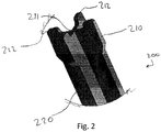
- Fig. 2 schematically illustrates a cleaning head 210 of a cleaning tool 200 according to a first embodiment.
- the cleaning head 210 comprises an inner wipe 211 and an outer wipe 212.
- the inner wipe 211 is recessed relative to the outer wipe 212, such that the inner wipe 211 is configured for cleaning a protrusion 114 as illustrated in Fig. 1B , and the outer wipe 212 is configured for cleaning an end wall 112 as illustrated in Fig. 1B .
- the cleaning head 210 is formed as a single rigid element with the outer wipe 212 comprising four rigid protrusions equally spaced around the inner wipe 211. More specifically, the cleaning head 210 is formed with a cross-shaped cross-section, where each of four branches of the cross shape comprise an inner part of the inner wipe 211 and an outer part of the outer wipe 212.
- the cleaning head 210 may, for example, be constructed from hard plastic or metal, and may be formed by moulding.
- 90A shore hardness polyurethane (PU), polyamide or polypropylene may be used to provide rigid parts of the cleaning tool.
- the cleaning tool 200 also comprises a shaft 220, which is partially shown in Fig. 2 .
- the shaft 220 also has a cross-shaped cross-section.
- Fig. 3A schematically illustrates a cleaning head 310 of a cleaning tool 300 according to a second embodiment.
- the second embodiment is similar to the first embodiment in that the cleaning head 310 comprises an inner wipe 311 and an outer wipe 312. However, the second embodiment illustrates several features each of which can be independently varied from the first embodiment.
- the inner wipe 311 of the second embodiment comprises a flexible blade which can bend when used to clean a heating chamber.
- This has an advantage in that the cleaning tool 300 can be used for heating chambers 110 where the depth L3 of the end wall 112 relative to the protrusion 114 (as shown in Fig. 1B ) is not fixed, and lies within a tolerance range.
- the flexible blade 311 can bend when pressed against the protrusion 114, so that the outer wipe 312 can reach the end wall 112. This ensures that the cleaning tool can reach all surfaces of the heating chamber.
- the inner wipe 311 may nevertheless have a cross-shaped cross-section.
- Flexible components of the cleaning head, including the flexible blade may, for example, comprise an elastomer such as rubber (e.g. EPDM, silicone or TPE).
- the rigid protrusions of the outer wipe 312 are barbs which spread outward meaning that a diameter of the cleaning head 310 is greater than a diameter of a shaft 320 attached to the cleaning head 310 (as shown in Figs. 3B and 3C ).
- the outer wipe 312 further comprises a base portion 313 attached to the rigid protrusions.
- the cleaning head 310 may then be constructed by attaching the inner wipe 311 within the base portion 313. More specifically, the inner wipe 311 may be adapted to form an attachment within the base portion, such as a snap-fit or press-fit attachment.
- the cleaning tool 300 may comprise a handle 330 at an end of the shaft 320 opposing the cleaning head 310.
- Fig. 3D schematically illustrates a cross-section of the cleaning tool 300 in use in a heating chamber 110 as described above.
- the inner wipe 311 presses against the protrusion 114, while the outer wipe 312 reaches the end wall 112. In this position, the cleaning tool 300 may be rotated to dislodge residue from consumables, and clean the aerosol generation device.
- the inner wipe 311 can deform to account for a tolerance in the depth L3 of the end wall 112 relative to the protrusion 114.
- the cleaning head 310 may instead comprise a rigid inner wipe 311 arranged to move in the base portion 313, and biased using a spring.
- the relative position of the inner wipe 311 and outer wipe 312 will adjust according to the depth L3 of the end wall 112 relative to the protrusion 114, so that the inner wipe and outer wipe can respectively clean the protrusion and the end wall when the cleaning tool 300 is pressed into the heating chamber 110.
- the cleaning head 210, 310 comprises four rigid protrusions forming the outer wipe 212, 312.
- the outer wipe 212, 312 may comprise only one rigid protrusion, or any plural number of rigid protrusions.
- the rigid protrusions need not be evenly spaced around the inner wipe 211, 311.
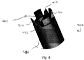
- Fig. 4 schematically illustrates a cleaning head 410 of a cleaning tool 400 according to a third embodiment.
- the third embodiment is similar to the first embodiment in that the cleaning head 410 comprises an inner wipe 411 and an outer wipe 412. However, the third embodiment illustrates further features which can be varied from the first embodiment.
- the cleaning head 410 comprises a rigid inner wipe 411 and rigid protrusions 412 of an outer wipe.
- the outer wipe further comprises four flexible wipes 414.
- the flexible wipes 414 can bend outwards when cleaning a heating chamber 110, to reach a greater diameter than the rigid protrusions 412.
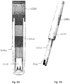
- Fig. 5A schematically illustrates a cleaning head 510 of a cleaning tool 500 according to a fourth embodiment.
- the cleaning head 510 comprises an outer wipe having one or more rigid protrusions 512 and one or more flexible wipes 514.
- the outer wipe comprises a base portion 513 and a flexible wipe is adapted to attach within the base portion 513, as shown in Figs. 5B and 5C .
- the flexible wipe 514 comprises a part of the outer wipe.
- the one or more rigid protrusions 512 and the flexible wipe 514 may be arranged at different points around the cleaning head 510.
- alternating rigid protrusions 512 and flexible wipes 514 are arranged around the cleaning head 510.
- the inner wipe comprises a flexible central blade 511.
- the inner wipe may be formed integrally with the flexible wipe (or wipes) 514 of the outer wipe, as a single flexible element that is adapted to attach within the base portion 513.
- the flexible central blade 511 is shorter than the flexible wipe 514, so that the flexible central blade 511 is configured for cleaning the protrusion 114 without preventing the outer wipe from reaching the end wall 112.
- the one or more rigid protrusions 512 may be barbs.
- Fig. 5D schematically illustrates a cross-section of the cleaning tool 500 in use in a heating chamber 110 as described above.
- the inner wipe 511 presses against the protrusion 114, while the outer wipe reaches the end wall 112.
- the flexible wipes 514 bend to fill the cross-section of the recessed annular portion between the protrusion 114, the side wall 111 and the end wall 112. This in particular helps to account for tolerances in the width L2 of the protrusion 114, and the depth L3 of the end wall 112 relative to the protrusion.
- the rigid protrusions 512 extend into the same recessed annular portion, between the flexible wipes 514. In this position, the cleaning tool 300 may be rotated to dislodge residue from consumables, and clean the aerosol generation device.
- the inner wipe and the outer wipe may be fully flexible.
- the cleaning head 510 may be modified to omit the rigid protrusions 512. (The base portion 513 may nevertheless be rigid). In this case, the cleaning head operates as shown in Fig. 5D , but the end wall 112 is cleaned by the one or more flexible wipes 514, without the use of any rigid protrusions.
- Figs. 6A and 6B schematically illustrate features of cleaning tools which are specifically adapted for a heating chamber 110 including one or more ribs 115, such as the heating chamber 110 shown in Fig. 1A .
- Fig. 6A illustrates a viewpoint from the end wall 112 of a heating chamber 110, looking through the heating chamber.
- a cleaning tool 600 can be seen with a cleaning head 610 directed towards the end wall 112.
- the heating chamber 110 appears as a side wall 111 from which four ribs 115 protrude into the heating chamber. Additionally, a cross-shaped protrusion 114 can be seen in the centre of the figure.
- the cleaning head 610 can be seen to include an inner wipe 611 and an outer wipe 612 comprising one or more (in this case four) rigid protrusions.
- the cleaning head 610 may, for example, be similar to any of the cleaning heads described above with corresponding features.
- a maximum width of the cleaning head 610 between two of the rigid protrusions 612 is close to a maximum internal width of the heating chamber 110 within the side wall 111.
- the ribs 115 protrude into the heating chamber 110 and the internal width of the heating chamber 110 is lower than the maximum at points where a rib 115 is present.
- a maximum width of the cleaning head 610 cannot fit into the heating chamber when aligned with the ribs 115.
- the rigid protrusions of the outer wipe 612 are spaced to fit past the one or more ribs when the cleaning tool 600 is appropriately aligned.
- the ribs 115 do not extend to the end wall 112, and the cleaning head 610 can rotate within the heating chamber without being obstructed by the ribs 115, when the cleaning head 610 is close to the end wall 112.
- Fig. 6B illustrates a cross-section of a heating chamber 110 from a side view, including the side wall 111, the end wall 112 and two ribs 115.
- a cleaning tool 700 comprising a cleaning head 710.
- the cleaning head 710 comprises an inner wipe 711, and an outer wipe comprising one or more rigid protrusions 712 and a flexible wipe 714, similarly to the cleaning head 510.
- the cleaning head may, more generally, be similar to any of the above-described cleaning heads with corresponding features.
- a maximum rigid width of the cleaning head 710 is smaller than a minimum internal width of the heating chamber 110 within the side wall 111, taking into account the one or more ribs 115.
- the one or more rigid protrusions 712 of the outer wipe are arranged to rotate alongside the one or more ribs 115, and there is no need to align the cleaning head 710 with the ribs 115 when inserting the cleaning tool 700 into the heating chamber 110. This is illustrated in Fig. 6B with dashed lines.
- the one or more rigid protrusions 714 do not reach as far as the side wall 111 when they are used to clean the end wall 112. However, as previously illustrated in Fig. 5D , the flexible wipe 714 may bend beyond the maximum rigid width of the cleaning head 710, to reach any part of the end wall 112 which is not reached by the rigid protrusions 714.
- the cleaning tool may be adapted for use in a heating chamber 110 comprising one or more ribs 115.
- Figs. 7A and 7B schematically illustrate features of cleaning tools having shafts.
- a cleaning tool may generally comprise a cleaning head 310, 510, a shaft 320, 520, and a handle 330, 530.
- Figs. 7A and 7B illustrate the shaft and handle, and may be combined with any of the above described cleaning heads.
- a cleaning tool 800 comprises a shaft 820, and the cleaning tool is arranged such that a user can hold one end of the shaft while using the cleaning head 810 (not shown) in a heating chamber.
- the shaft 820 comprises a visual indicator (821 in Fig. 7A , 822 in Fig. 7B ) arranged to indicate to the user when the cleaning head is near to the end wall.
- the visual indicator is simply a structural feature (e.g. an arrow 821 or a flange 822) located at a distance from the cleaning head corresponding to an expected length of the heating chamber.
- the visual indicator may be aligned with the lid 150 (see Fig. 1 ) and the user knows that the cleaning head is near to the end wall.
- the visual indicator may be an electronic component (e.g. LED) and the cleaning head may comprise a sensor configured to detect proximity or pressure between the cleaning head and the protrusion or end wall of the heating chamber. When the detected proximity or pressure exceeds a threshold, the visual indicator may be activated.
- a handle 830 is additionally provided at an end of the shaft 820 for the user to hold the cleaning tool 800.
- the handle may, for example, comprise a thermoplastic such as acrylonitrile butadiene styrene (ABS) and/or elastomer.
- the cleaning tool may be provided as part of an aerosol generation device, and may be arranged and controlled to automatically enter and clean a heating chamber, for example after a consumable is removed.
- the cleaning tool 900 may optionally be provided with a cap 940 for covering the cleaning head 910.
- a cap 940 allows the cleaning tool 900 to be stored when not in use without creating a mess.
- the cap 940 may, for example, comprise a thermoplastic such as acrylonitrile butadiene styrene (ABS) and/or elastomer.
- the cleaning tool has a cleaning head 910, a shaft 920 and a handle 930 which may be according to any of the previous descriptions.
- the handle 930 is attached to a cap 940 by a tether 950.
- the tether 950 has the advantage of ensuring that the cap 940 is not lost from the cleaning tool 900.
- the tether 950 may comprise bungs adapted to fit with the handle 930 and the cap 940, so that the tool can be easily assembled from different components.
- the tether may, for example, comprise an elastomer such as rubber.
- a cleaning tool 1000 may comprise a cap 1040 adapted to releasably attach to the cleaning head 1010 (either directly or attaching to the cleaning head via the shaft 1020 and/or the handle 1030).
- the cleaning head 1010 may be similar to any of the above-described cleaning heads.
- the releasable attachment may be a press fit in which friction between a surface of the handle 1030 and a surface of the cap 1040 holds the cap in place.
- the cap 1040 may releasably attach to the cleaning head 1010 in a first position at which the cleaning head 1010 is covered.
- the cap 1040 may releasably attach to the cleaning head 1010 in a second position at which the cleaning head 1010 is not covered. In this position, the cap 1040 is arranged as a handle extension. This has the advantage that the cleaning tool 1000 has a large grip for a user to hold during use, while minimizing the length of the cleaning tool when it is stored. In embodiments where the handle 1030 is omitted, the cap 1040 acts as a complete handle rather than a handle extension.
- an end of the handle 1030 may serve as a visual indicator arranged to indicate to the user when the cleaning head 1010 is near to the end wall 112 of the heating chamber 110.
- the length of the shaft 1020 may be chosen to correspond to an expected length of the heating chamber.
- Figs. 8 and 9 may be combined to provide a cover that cannot be lost (due to the tether) while also providing an extendible handle.
- a rigid part of the cleaning head may be moulded as a single component with a shaft, and optionally with a handle. Any flexible part of the cleaning head may then be attached as described above.
- a rigid part of the cleaning head, a shaft, and a handle may be formed in two or more mouldings.
- a shaft may have a solid cross section, providing stiffness and effectively translating rotation between the handle and the cleaning head.
- the shaft may have a cut-away cross-section, such as a hollow tube or a cross-shaped cross-section, reducing stiffness and reducing the torque required to apply large forces to dislodge residue at the cleaning head. More specifically, by allowing the handle 330 to rotate relative to the cleaning head 310, the shaft 320 can store mechanical energy which can be released at the cleaning head 310.
Abstract
Description
- The present disclosure relates to cleaning tools for use in aerosol generation devices. Aerosol generation devices are designed to heat or burn an aerosol generation substrate, such as tobacco, to generate an aerosol. This typically leaves a residue in the aerosol generation device. A cleaning tool is used to remove the residue.
- Aerosol generating devices are increasingly popular for consumers as reduced risk nicotine delivery products, including e-cigarettes and tobacco vapour products. Such devices heat an aerosol generating substance in the form of a consumable within a heating chamber to produce a vapour to be inhaled by a user.
- Heating chambers generally comprise a heat conductive housing or shell defining an internal volume to hold a consumable and an opening through which the consumable may be received. A heater may be employed internally or externally to provide the increased temperature to the heating chamber. Most commonly such heating chambers are heated from the outside, with the conductive shell transferring the heat to the internal volume. One means to heat such heating chamber uses a thin film heater which conforms to a surface of a heating chamber to ensure efficient heating of a consumable received within the chamber.
- Often heating chambers need to be formed with a specific shape to accept a specific type of consumable. The internal surfaces of the heating chamber may also need to take a specific surface profile shape to hold the consumable and efficiently transfer heat to the consumable.
- One type of heating chamber has a closed end wall comprising multiple different surfaces. These surfaces may be arranged as an inner protrusion that protrudes from a central portion of the end wall into the heating chamber, and an annular ring surrounding the protrusion. This specific shape of the end wall can, for example, provide air gap for air circulation inside the consumable, assist with mounting the heating chamber within an aerosol generation device or assist in reducing the chance that a consumable becomes stuck to the end wall.
- However, known cleaning tools are not adapted to clean such a heating chamber, and may be ineffective in cleaning all surfaces of the heating chamber. Keeping the heating chamber clean is necessary because residue from aerosol generation can block air flow and/or negatively affect a taste of aerosol generated by the aerosol generation device. Accordingly, it is desirable to provide a heating tool for cleaning a heating chamber of an aerosol generation device, wherein the heating chamber comprises a side wall, an end wall, and protrusion that protrudes from a central portion of the end wall into the heating chamber.
- According to a first aspect, the present disclosure provides a cleaning tool for cleaning a heating chamber of an aerosol generation device, wherein the heating chamber comprises a side wall, an end wall, and protrusion that protrudes from a central portion of the end wall into the heating chamber, wherein the cleaning tool comprises a cleaning head, and the cleaning head comprises: an inner wipe configured for cleaning the protrusion; and an outer wipe configured for cleaning the end wall.
- Optionally, the inner wipe and/or the outer wipe comprises a flexible wipe.
- Optionally, the outer wipe comprises one or more rigid protrusions and the inner wipe comprises a flexible blade.
- Optionally, the outer wipe further comprises a base portion attached to the one or more rigid protrusions, and the inner wipe is adapted to attach within the base portion.
- Optionally, the outer wipe comprises one or more rigid protrusions and a flexible wipe.
- Optionally, the outer wipe comprises a base portion attached to the one or more rigid protrusions, and the flexible wipe is adapted to attach within the base portion, the outer wipe and the one or more rigid protrusions being arranged such that the outer wipe can extend or bend to reach the end wall.
- Optionally, the inner wipe comprises a flexible central blade configured for cleaning the protrusion, the central blade being shorter than the flexible wipe of the outer wipe.
- Optionally, the central blade and the flexible wipe of the outer wipe are formed as a single flexible element.
- Optionally, the cleaning tool is for a heating chamber comprising one or more ribs arranged along the side wall around an inner perimeter of the heating chamber, and the one or more rigid protrusions of the outer wipe are spaced to fit past the one or more ribs when the cleaning tool is appropriately aligned.
- Optionally, the cleaning tool is for a heating chamber comprising one or more ribs arranged along the side wall around an inner perimeter of the heating chamber, and the one or more rigid protrusions of the outer wipe are arranged to rotate alongside the one or more ribs.
- Optionally, the one or more rigid protrusions are barbs.
- Optionally, the cleaning tool comprises a shaft, and arranged such that a user can hold one end of the shaft while using the cleaning head in the heating chamber, the shaft comprising a visual indicator arranged to indicate to the user when the cleaning head is near to the end wall.
- Optionally, the cleaning tool further comprises a cap for covering the cleaning head, and a tether attaching the cap to the cleaning head.
- Optionally, the cleaning tool comprises a cap for covering the cleaning head, wherein the cap is adapted to releasably attach to the cleaning head: in a first position at which the cleaning head is covered and in a second position at which the cleaning head is not covered and the cap is arranged as a handle or as a handle extension.
-
-
Figs. 1A and 1B schematically illustrate a cross-section of an aerosol generation device, and in particular illustrate a heating chamber of the aerosol generation device; -
Fig. 2 schematically illustrates a cleaning head of a cleaning tool according to a first embodiment; -
Figs. 3A to 3D schematically illustrates a cleaning head of a cleaning tool according to a second embodiment; -
Fig. 4 schematically illustrates a cleaning head of a cleaning tool according to a third embodiment; -
Figs. 5A to 5D schematically illustrate a cleaning head of a cleaning tool according to a fourth embodiment; -
Figs. 6A and 6B schematically illustrate features of cleaning tools adapted for a heating chamber including one or more ribs; -
Figs. 7A and 7B schematically illustrate features of cleaning tools having shafts; -
Fig. 8 schematically illustrates a cross section of a cleaning tool comprising a cap; -
Figs. 9A and 9B schematically illustrate another cleaning tool comprising a cap. -
Fig. 1A schematically illustrates an example of an aerosol generation device 100, in cross-section. This serves as an example of a type of aerosol generation device in which the subsequently described cleaning tool may be used. - The aerosol generation device 100 comprises a
heating chamber 110, aheater 120,control circuitry 130, anelectrical power source 140, and alid 150. - The
heating chamber 110 has aside wall 111, andend wall 112 and anopen end 113 opposed to theend wall 112. The heating chamber may, for example, have an approximately cylindrical shape. - Additionally, the
heating chamber 110 comprises aprotrusion 114 that protrudes from a central portion of theend wall 112 into an inner volume of the heating chamber. This protrusion on an inner surface of the heating chamber may correspond to a recess on an outer surface of the heating chamber. Alternatively, the outer surface may be flat along theend wall 112. Theprotrusion 114 is useful because it provides a support to a substrate carrier (e.g. aerosolisable tobacco) contained in the consumable while maintaining an air gap allowing air to enter in the substrate carrier. Generally, the protrusion has a lower surface area (or diameter) than the surface area of an end of the consumable which rests against the protrusion, so that air can pass along the side of the protrusion and inside the consumable. If there was no protrusion, air could be blocked by consumable resting against theend wall 112. - Furthermore, the
heating chamber 110 comprises a plurality ofribs 115 arranged along theside wall 111. As described herein, arib 115 is an elongate protrusion extending along theside wall 111 in a direction between theend wall 112 and theopen end 113. Theribs 115 have the effect of ensuring that, when a consumable is present in theheating chamber 110, an air flow channel is maintained between the consumable and theside wall 111. This means that air can circulate through the consumable by flowing along theside wall 111 to theend wall 112, and then through the consumable. Circulating air can carry a generated aerosol out of the consumable for a user to inhale the aerosol. Such an air flow channel can be achieved with only onerib 115, or with two ormore ribs 115 spaced around theside wall 111. - The
heater 120 is arranged to supply heat to theheating chamber 110. In this example, theheater 120 is a film heater arranged on around theside wall 111 of theheating chamber 110. However, in other examples, theheater 120 may be another type of heater, arranged to supply heat through theside wall 111 or through theend wall 112, or may instead be arranged inside the inner volume of the heating chamber, or may be integrated within theside wall 111 or theend wall 112. - The
control circuitry 130 is configured to receive power from theelectrical power source 140, and to drive theheater 120. Thecontrol circuitry 130 may be arranged to receive user inputs from one or more controls (e.g. buttons or sliders) on the aerosol generation device 100, and may be configured to efficiently heat a consumable in theheating chamber 110 using theheater 120 according to a set of processing instructions or a timing sequence. - The
lid 150 is arranged to be moveable between a closed position, in which access to theopen end 113 of the heating chamber is prevented, and an open position, in which theopen end 113 of the heating chamber is accessible. With thelid 150 in the open position, a consumable or a cleaning tool may be inserted into, used in, and removed from theheating chamber 110. -
Fig. 1B schematically illustrates detail of theheating chamber 110 near theend wall 112, in particular showing a cross section through theside wall 111 and theend wall 112. - As shown in
Fig. 1B , the inner volume of theheating chamber 110 has a width L1 between two opposing parts of theside wall 111. In a same direction, theprotrusion 114 has a width L2 which is smaller than L1. Theprotrusion 114 protrudes from a central portion of theend wall 112, and a remaining part of theend wall 112 is recessed by a depth L3 relative to theprotrusion 114. - In one specific example, the width L1 may be 7.6mm with a tolerance of ±0.05mm, the width L2 may be 4mm with a greater tolerance of ±0.3mm, and the depth L3 may be 1mm with a tolerance of ±0.2mm.
- The
heating chamber 110 may be cylindrically symmetric such that the cross-section ofFig. 1B remains the same as theheating chamber 110 is rotated. In other words, theside wall 111 may be a circular wall of the heating chamber and theprotrusion 114 may be a circular protrusion from theend wall 112. However, other shapes are possible. For example, theside wall 111 and/or theprotrusion 114 may have an elliptical or polygonal cross-section. As a further example, theprotrusion 114 may, for example, have a cross-shape. - When a consumable is inserted into the
heating chamber 110, the consumable is generally dimensioned wider than theprotrusion 114, and partially rests against theprotrusion 114 and is partially suspended above theend wall 112. - As the consumable is heated and aerosol generated out of it, the consumable may produce a residue and may thus adhere to the
protrusion 114 on which it rests. However, since there is space adjacent to the consumable below the consumable and/or to the side of the consumable, it is relatively easy for a user to break any adhesion between the consumable and theheating chamber 110 by twisting or sideways motion of the consumable. -
Fig. 2 schematically illustrates acleaning head 210 of acleaning tool 200 according to a first embodiment. - The cleaning
head 210 comprises an inner wipe 211 and an outer wipe 212. The inner wipe 211 is recessed relative to the outer wipe 212, such that the inner wipe 211 is configured for cleaning aprotrusion 114 as illustrated inFig. 1B , and the outer wipe 212 is configured for cleaning anend wall 112 as illustrated inFig. 1B . - In this embodiment, the cleaning
head 210 is formed as a single rigid element with the outer wipe 212 comprising four rigid protrusions equally spaced around the inner wipe 211. More specifically, the cleaninghead 210 is formed with a cross-shaped cross-section, where each of four branches of the cross shape comprise an inner part of the inner wipe 211 and an outer part of the outer wipe 212. - The cleaning
head 210 may, for example, be constructed from hard plastic or metal, and may be formed by moulding. As a specific example, 90A shore hardness polyurethane (PU), polyamide or polypropylene may be used to provide rigid parts of the cleaning tool. - The
cleaning tool 200 also comprises ashaft 220, which is partially shown inFig. 2 . In this embodiment, theshaft 220 also has a cross-shaped cross-section. -
Fig. 3A schematically illustrates acleaning head 310 of acleaning tool 300 according to a second embodiment. - The second embodiment is similar to the first embodiment in that the cleaning
head 310 comprises an inner wipe 311 and an outer wipe 312. However, the second embodiment illustrates several features each of which can be independently varied from the first embodiment. - Firstly, instead of having a rigid inner wipe 211, the inner wipe 311 of the second embodiment comprises a flexible blade which can bend when used to clean a heating chamber. This has an advantage in that the
cleaning tool 300 can be used forheating chambers 110 where the depth L3 of theend wall 112 relative to the protrusion 114 (as shown inFig. 1B ) is not fixed, and lies within a tolerance range. Theflexible blade 311 can bend when pressed against theprotrusion 114, so that the outer wipe 312 can reach theend wall 112. This ensures that the cleaning tool can reach all surfaces of the heating chamber. As shown inFig. 3A , the inner wipe 311 may nevertheless have a cross-shaped cross-section. Flexible components of the cleaning head, including the flexible blade, may, for example, comprise an elastomer such as rubber (e.g. EPDM, silicone or TPE). - Secondly, in the second embodiment, the rigid protrusions of the outer wipe 312 are barbs which spread outward meaning that a diameter of the
cleaning head 310 is greater than a diameter of ashaft 320 attached to the cleaning head 310 (as shown inFigs. 3B and 3C ). - Thirdly, in the second embodiment, the outer wipe 312 further comprises a
base portion 313 attached to the rigid protrusions. As shown inFigs. 3B and 3C , the cleaninghead 310 may then be constructed by attaching the inner wipe 311 within thebase portion 313. More specifically, the inner wipe 311 may be adapted to form an attachment within the base portion, such as a snap-fit or press-fit attachment. - As also shown in
Figs. 3B and 3C , thecleaning tool 300 may comprise ahandle 330 at an end of theshaft 320 opposing thecleaning head 310. -
Fig. 3D schematically illustrates a cross-section of thecleaning tool 300 in use in aheating chamber 110 as described above. As shown inFig. 3D , the inner wipe 311 presses against theprotrusion 114, while the outer wipe 312 reaches theend wall 112. In this position, thecleaning tool 300 may be rotated to dislodge residue from consumables, and clean the aerosol generation device. By using a flexible inner wipe 311, the inner wipe 311 can deform to account for a tolerance in the depth L3 of theend wall 112 relative to theprotrusion 114. - In a variant of the second embodiment (not shown), rather than using a flexible inner wipe 311, the cleaning
head 310 may instead comprise a rigid inner wipe 311 arranged to move in thebase portion 313, and biased using a spring. With this construction, the relative position of the inner wipe 311 and outer wipe 312 will adjust according to the depth L3 of theend wall 112 relative to theprotrusion 114, so that the inner wipe and outer wipe can respectively clean the protrusion and the end wall when thecleaning tool 300 is pressed into theheating chamber 110. - In the first and second embodiments, the cleaning
head -
Fig. 4 schematically illustrates acleaning head 410 of acleaning tool 400 according to a third embodiment. - The third embodiment is similar to the first embodiment in that the cleaning
head 410 comprises an inner wipe 411 and an outer wipe 412. However, the third embodiment illustrates further features which can be varied from the first embodiment. - More specifically, in the third embodiment, the cleaning
head 410 comprises a rigid inner wipe 411 andrigid protrusions 412 of an outer wipe. However, in this embodiment, the outer wipe further comprises fourflexible wipes 414. Theflexible wipes 414 can bend outwards when cleaning aheating chamber 110, to reach a greater diameter than therigid protrusions 412. - Furthermore, if the
flexible wipes 414 are longer than therigid protrusions 412, theflexible wipes 414 can serve a similar function to theflexible blade 311 of the second embodiment, by bending when pressed against theend wall 112, so that the inner wipe 411 can reach theprotrusion 114. This ensures that the cleaning tool can reach all surfaces of the heating chamber
Fig. 5A schematically illustrates acleaning head 510 of acleaning tool 500 according to a fourth embodiment. - Like the third embodiment, in the fourth embodiment, the cleaning
head 510 comprises an outer wipe having one or morerigid protrusions 512 and one or moreflexible wipes 514. - In the fourth embodiment, similarly to the second embodiment, the outer wipe comprises a
base portion 513 and a flexible wipe is adapted to attach within thebase portion 513, as shown inFigs. 5B and 5C . However, in the case of the fourth embodiment, the flexible wipe 514 comprises a part of the outer wipe. In order to allow the flexible wipe (or wipes) 514 to extend or bend to reach theend wall 112 and/or theside wall 111, the one or morerigid protrusions 512 and the flexible wipe 514 may be arranged at different points around the cleaninghead 510. For example, as shown inFig. 5A , alternatingrigid protrusions 512 andflexible wipes 514 are arranged around the cleaninghead 510. With this arrangement, therigid protrusions 512 can be used to scrape the end wall and loosen strongly adhered consumable residue, and theflexible wipes 514 can displace looser consumable residue and more effectively reach the entire surface of theend wall 112. - Additionally, like the second embodiment, the inner wipe comprises a flexible
central blade 511. In the case of the fourth embodiment, the inner wipe may be formed integrally with the flexible wipe (or wipes) 514 of the outer wipe, as a single flexible element that is adapted to attach within thebase portion 513. In some examples, the flexiblecentral blade 511 is shorter than the flexible wipe 514, so that the flexiblecentral blade 511 is configured for cleaning theprotrusion 114 without preventing the outer wipe from reaching theend wall 112. - Furthermore, as in the second embodiment, the one or more
rigid protrusions 512 may be barbs. -
Fig. 5D schematically illustrates a cross-section of thecleaning tool 500 in use in aheating chamber 110 as described above. As shown inFig. 5D , the inner wipe 511 presses against theprotrusion 114, while the outer wipe reaches theend wall 112. In particular, as shown inFig. 5D , theflexible wipes 514 bend to fill the cross-section of the recessed annular portion between theprotrusion 114, theside wall 111 and theend wall 112. This in particular helps to account for tolerances in the width L2 of theprotrusion 114, and the depth L3 of theend wall 112 relative to the protrusion. Simultaneously, therigid protrusions 512 extend into the same recessed annular portion, between the flexible wipes 514. In this position, thecleaning tool 300 may be rotated to dislodge residue from consumables, and clean the aerosol generation device. - In a further alternative to the above described embodiments, the inner wipe and the outer wipe may be fully flexible. For example, the cleaning
head 510 may be modified to omit therigid protrusions 512. (Thebase portion 513 may nevertheless be rigid). In this case, the cleaning head operates as shown inFig. 5D , but theend wall 112 is cleaned by the one or moreflexible wipes 514, without the use of any rigid protrusions. -
Figs. 6A and 6B schematically illustrate features of cleaning tools which are specifically adapted for aheating chamber 110 including one ormore ribs 115, such as theheating chamber 110 shown inFig. 1A . -
Fig. 6A illustrates a viewpoint from theend wall 112 of aheating chamber 110, looking through the heating chamber. A cleaning tool 600 can be seen with a cleaning head 610 directed towards theend wall 112. - From this viewpoint, the
heating chamber 110 appears as aside wall 111 from which fourribs 115 protrude into the heating chamber. Additionally, across-shaped protrusion 114 can be seen in the centre of the figure. - Behind the
protrusion 114, and within theside wall 111, the cleaning head 610 can be seen to include an inner wipe 611 and an outer wipe 612 comprising one or more (in this case four) rigid protrusions. The cleaning head 610 may, for example, be similar to any of the cleaning heads described above with corresponding features. - A maximum width of the cleaning head 610 between two of the
rigid protrusions 612 is close to a maximum internal width of theheating chamber 110 within theside wall 111. However, theribs 115 protrude into theheating chamber 110 and the internal width of theheating chamber 110 is lower than the maximum at points where arib 115 is present. As a result, a maximum width of the cleaning head 610 cannot fit into the heating chamber when aligned with theribs 115. In order to accommodate the presence of one ormore ribs 115, the rigid protrusions of the outer wipe 612 are spaced to fit past the one or more ribs when the cleaning tool 600 is appropriately aligned. - In this example, the
ribs 115 do not extend to theend wall 112, and the cleaning head 610 can rotate within the heating chamber without being obstructed by theribs 115, when the cleaning head 610 is close to theend wall 112. -
Fig. 6B illustrates a cross-section of aheating chamber 110 from a side view, including theside wall 111, theend wall 112 and tworibs 115. - Inside the
heating chamber 110 is a cleaning tool 700 comprising acleaning head 710. The cleaninghead 710 comprises an inner wipe 711, and an outer wipe comprising one or morerigid protrusions 712 and a flexible wipe 714, similarly to thecleaning head 510. The cleaning head may, more generally, be similar to any of the above-described cleaning heads with corresponding features. - In the example of
Fig. 6B , a maximum rigid width of thecleaning head 710 is smaller than a minimum internal width of theheating chamber 110 within theside wall 111, taking into account the one ormore ribs 115. In other words, the one or morerigid protrusions 712 of the outer wipe are arranged to rotate alongside the one ormore ribs 115, and there is no need to align thecleaning head 710 with theribs 115 when inserting the cleaning tool 700 into theheating chamber 110. This is illustrated inFig. 6B with dashed lines. - In this example, the one or more
rigid protrusions 714 do not reach as far as theside wall 111 when they are used to clean theend wall 112. However, as previously illustrated inFig. 5D , the flexible wipe 714 may bend beyond the maximum rigid width of thecleaning head 710, to reach any part of theend wall 112 which is not reached by therigid protrusions 714. - Accordingly, either by controlling spacing between rigid protrusions, as in
Fig. 6A , or by controlling a maximum rigid width of the cleaning head, as inFig. 6B , the cleaning tool may be adapted for use in aheating chamber 110 comprising one ormore ribs 115. -
Figs. 7A and 7B schematically illustrate features of cleaning tools having shafts. - More specifically, referring back to the broader views shown in
Figs. 3C and5C , a cleaning tool may generally comprise acleaning head shaft handle Figs. 7A and 7B illustrate the shaft and handle, and may be combined with any of the above described cleaning heads. - In both of
Figs. 7A and 7B , a cleaning tool 800 comprises ashaft 820, and the cleaning tool is arranged such that a user can hold one end of the shaft while using the cleaning head 810 (not shown) in a heating chamber. - The
shaft 820 comprises a visual indicator (821 inFig. 7A , 822 inFig. 7B ) arranged to indicate to the user when the cleaning head is near to the end wall. Here "near As shown inFigs. 7A and 7B , the visual indicator is simply a structural feature (e.g. anarrow 821 or a flange 822) located at a distance from the cleaning head corresponding to an expected length of the heating chamber. When the visual indicator is aligned with the lid 150 (seeFig. 1 ), the user knows that the cleaning head is near to the end wall. In other embodiments, more complex visual indicators may be used. For example, the visual indicator may be an electronic component (e.g. LED) and the cleaning head may comprise a sensor configured to detect proximity or pressure between the cleaning head and the protrusion or end wall of the heating chamber. When the detected proximity or pressure exceeds a threshold, the visual indicator may be activated. - In the embodiments shown in
Figs. 7A and 7B , ahandle 830 is additionally provided at an end of theshaft 820 for the user to hold the cleaning tool 800. The handle may, for example, comprise a thermoplastic such as acrylonitrile butadiene styrene (ABS) and/or elastomer. - The handle, and even the shaft, may be omitted in some embodiments. For example, the cleaning tool may be provided as part of an aerosol generation device, and may be arranged and controlled to automatically enter and clean a heating chamber, for example after a consumable is removed.
- Turning to
Fig. 8 , the cleaning tool 900 may optionally be provided with acap 940 for covering thecleaning head 910. This is useful because thecleaning head 910 may become dirty when used to clean an aerosol generation device, and residue from consumables may become stuck to thecleaning head 910. Accordingly, acap 940 allows the cleaning tool 900 to be stored when not in use without creating a mess. As with thehandle 930, thecap 940 may, for example, comprise a thermoplastic such as acrylonitrile butadiene styrene (ABS) and/or elastomer. - More specifically, in the embodiment shown in
Fig. 8 , the cleaning tool has acleaning head 910, ashaft 920 and ahandle 930 which may be according to any of the previous descriptions. Additionally, thehandle 930 is attached to acap 940 by atether 950. Thetether 950 has the advantage of ensuring that thecap 940 is not lost from the cleaning tool 900. As shown inFig. 8 , thetether 950 may comprise bungs adapted to fit with thehandle 930 and thecap 940, so that the tool can be easily assembled from different components. As with flexible parts of any of the above-described cleaning heads, the tether may, for example, comprise an elastomer such as rubber. - Additionally, as shown in
Figs. 9A and 9B , a cleaning tool 1000 may comprise acap 1040 adapted to releasably attach to the cleaning head 1010 (either directly or attaching to the cleaning head via theshaft 1020 and/or the handle 1030). As withFig. 8 , thecleaning head 1010 may be similar to any of the above-described cleaning heads. - As shown in
Fig. 9A , the releasable attachment may be a press fit in which friction between a surface of thehandle 1030 and a surface of thecap 1040 holds the cap in place. - As shown in
Fig. 9A , thecap 1040 may releasably attach to thecleaning head 1010 in a first position at which thecleaning head 1010 is covered. - Additionally, as shown in
Fig. 9B , thecap 1040 may releasably attach to thecleaning head 1010 in a second position at which thecleaning head 1010 is not covered. In this position, thecap 1040 is arranged as a handle extension. This has the advantage that the cleaning tool 1000 has a large grip for a user to hold during use, while minimizing the length of the cleaning tool when it is stored. In embodiments where thehandle 1030 is omitted, thecap 1040 acts as a complete handle rather than a handle extension. - In the embodiment shown in
Fig. 9B , an end of thehandle 1030 may serve as a visual indicator arranged to indicate to the user when thecleaning head 1010 is near to theend wall 112 of theheating chamber 110. In other words, the length of theshaft 1020 may be chosen to correspond to an expected length of the heating chamber. - The features of
Figs. 8 and9 may be combined to provide a cover that cannot be lost (due to the tether) while also providing an extendible handle. - In the above described embodiments, a rigid part of the cleaning head may be moulded as a single component with a shaft, and optionally with a handle. Any flexible part of the cleaning head may then be attached as described above. Alternatively, a rigid part of the cleaning head, a shaft, and a handle may be formed in two or more mouldings.
- In the above described embodiments, a shaft may have a solid cross section, providing stiffness and effectively translating rotation between the handle and the cleaning head. Alternatively, the shaft may have a cut-away cross-section, such as a hollow tube or a cross-shaped cross-section, reducing stiffness and reducing the torque required to apply large forces to dislodge residue at the cleaning head. More specifically, by allowing the
handle 330 to rotate relative to thecleaning head 310, theshaft 320 can store mechanical energy which can be released at thecleaning head 310.
Claims (14)
- A cleaning tool for cleaning a heating chamber of an aerosol generation device, wherein the heating chamber comprises a side wall, an end wall, and protrusion that protrudes from a central portion of the end wall into the heating chamber,
wherein the cleaning tool comprises a cleaning head, and the cleaning head comprises:an inner wipe configured for cleaning the protrusion; andan outer wipe configured for cleaning the end wall. - A cleaning tool according to claim 1, wherein the inner wipe and/or the outer wipe comprises a flexible wipe.
- A cleaning tool according to claim 2, wherein the outer wipe comprises one or more rigid protrusions and the inner wipe comprises a flexible blade.
- A cleaning tool according to claim 3, wherein the outer wipe further comprises a base portion attached to the one or more rigid protrusions, and the inner wipe is adapted to attach within the base portion.
- A cleaning tool according to claim 2, wherein the outer wipe comprises one or more rigid protrusions and a flexible wipe.
- A cleaning tool according to claim 5, wherein the outer wipe comprises a base portion attached to the one or more rigid protrusions, and the flexible wipe is adapted to attach within the base portion, the outer wipe and the one or more rigid protrusions being arranged such that the outer wipe can extend or bend to reach the end wall.
- A cleaning tool according to claim 5 or claim 6, wherein the inner wipe comprises a flexible central blade configured for cleaning the protrusion, the central blade being shorter than the flexible wipe of the outer wipe.
- A cleaning tool according to claim 7, wherein the central blade and the flexible wipe of the outer wipe are formed as a single flexible element.
- A cleaning tool according to any of claims 3 to 8, wherein the cleaning tool is for a heating chamber comprising one or more ribs arranged along the side wall around an inner perimeter of the heating chamber, and the one or more rigid protrusions of the outer wipe are spaced to fit past the one or more ribs when the cleaning tool is appropriately aligned.
- A cleaning tool according to any of claims 3 to 9, wherein the cleaning tool is for a heating chamber comprising one or more ribs arranged along the side wall around an inner perimeter of the heating chamber, and the one or more rigid protrusions of the outer wipe are arranged to rotate alongside the one or more ribs.
- A cleaning tool according to any of claims 3 to 10, wherein the one or more rigid protrusions are barbs.
- A cleaning tool according to any preceding claim, comprising a shaft, and arranged such that a user can hold one end of the shaft while using the cleaning head in the heating chamber, the shaft comprising a visual indicator arranged to indicate to the user when the cleaning head is near to the end wall.
- A cleaning tool according to any preceding claim, further comprising a cap for covering the cleaning head, and a tether attaching the cap to the cleaning head.
- A cleaning tool according to any preceding claim, comprising a cap for covering the cleaning head, wherein the cap is adapted to releasably attach to the cleaning head:in a first position at which the cleaning head is covered andin a second position at which the cleaning head is not covered and the cap is arranged as a handle or as a handle extension.
Priority Applications (1)
| Application Number | Priority Date | Filing Date | Title |
|---|---|---|---|
| EP19218019.8A EP3838428A1 (en) | 2019-12-19 | 2019-12-19 | Cleaning tool for aerosol generation device |
Applications Claiming Priority (1)
| Application Number | Priority Date | Filing Date | Title |
|---|---|---|---|
| EP19218019.8A EP3838428A1 (en) | 2019-12-19 | 2019-12-19 | Cleaning tool for aerosol generation device |
Publications (1)
| Publication Number | Publication Date |
|---|---|
| EP3838428A1 true EP3838428A1 (en) | 2021-06-23 |
Family
ID=69156153
Family Applications (1)
| Application Number | Title | Priority Date | Filing Date |
|---|---|---|---|
| EP19218019.8A Pending EP3838428A1 (en) | 2019-12-19 | 2019-12-19 | Cleaning tool for aerosol generation device |
Country Status (1)
| Country | Link |
|---|---|
| EP (1) | EP3838428A1 (en) |
Citations (3)
| Publication number | Priority date | Publication date | Assignee | Title |
|---|---|---|---|---|
| EP1249282A2 (en) * | 2001-04-11 | 2002-10-16 | NTT Advanced Technology Corporation | Cleaning tool for optical connector |
| EP2201850A1 (en) * | 2008-12-24 | 2010-06-30 | Philip Morris Products S.A. | An article including identification information for use in an electrically heated smoking system |
| US20190117332A1 (en) * | 2015-01-28 | 2019-04-25 | Neomed, Inc. | Cleaning device and method for using the same |
-
2019
- 2019-12-19 EP EP19218019.8A patent/EP3838428A1/en active Pending
Patent Citations (3)
| Publication number | Priority date | Publication date | Assignee | Title |
|---|---|---|---|---|
| EP1249282A2 (en) * | 2001-04-11 | 2002-10-16 | NTT Advanced Technology Corporation | Cleaning tool for optical connector |
| EP2201850A1 (en) * | 2008-12-24 | 2010-06-30 | Philip Morris Products S.A. | An article including identification information for use in an electrically heated smoking system |
| US20190117332A1 (en) * | 2015-01-28 | 2019-04-25 | Neomed, Inc. | Cleaning device and method for using the same |
Similar Documents
| Publication | Publication Date | Title |
|---|---|---|
| US11744690B2 (en) | Toothbrush tip | |
| USD863772S1 (en) | Electric toothbrush head | |
| US8177450B2 (en) | Structure for make-up pen with function of vibration massage | |
| EP2918243B1 (en) | Replacement brush head for an electric toothbrush | |
| CN107981949B (en) | Cleaning implement | |
| CN107981950B (en) | Cleaning implement | |
| US10463462B2 (en) | Electric toothbrush apparatus | |
| USD866981S1 (en) | Electric facial and body cleansing brush | |
| CN109068832B (en) | Heated applicator system with reusable components | |
| WO2005023144A3 (en) | Electric toothbrushes and replaceable components | |
| WO2014054489A1 (en) | Cosmetic tool | |
| EP3661390A1 (en) | Systems, devices, and methods of a self-activation use odometer for a skin care brush | |
| US6809302B1 (en) | Bottle warming device | |
| EP3838428A1 (en) | Cleaning tool for aerosol generation device | |
| US6804839B1 (en) | Combination toilet brush/plunger apparatus | |
| TW200406170A (en) | Cleaning utensil | |
| USD572011S1 (en) | Grill brush with offset handle | |
| CN108542096A (en) | A kind of retainer and external member and electrical equipment for the handle end of brush to be clamped | |
| USD887721S1 (en) | Paint brush with angled handle and without a ferrule | |
| US8906297B1 (en) | Toothbrush sanitizer | |
| US10709231B2 (en) | Rotary scrubber | |
| EP3159447A1 (en) | Stain removing device and stain removing unit | |
| EP3200651B1 (en) | Oral care device having a pump-free fluid delivery system | |
| CA3014803A1 (en) | Nested brush | |
| US10398537B2 (en) | Attachment structure for a personal care appliance, a personal care appliance and a method |
Legal Events
| Date | Code | Title | Description |
|---|---|---|---|
| PUAI | Public reference made under article 153(3) epc to a published international application that has entered the european phase |
Free format text: ORIGINAL CODE: 0009012 |
|
| STAA | Information on the status of an ep patent application or granted ep patent |
Free format text: STATUS: THE APPLICATION HAS BEEN PUBLISHED |
|
| AK | Designated contracting states |
Kind code of ref document: A1 Designated state(s): AL AT BE BG CH CY CZ DE DK EE ES FI FR GB GR HR HU IE IS IT LI LT LU LV MC MK MT NL NO PL PT RO RS SE SI SK SM TR |
|
| STAA | Information on the status of an ep patent application or granted ep patent |
Free format text: STATUS: REQUEST FOR EXAMINATION WAS MADE |
|
| 17P | Request for examination filed |
Effective date: 20211222 |
|
| RBV | Designated contracting states (corrected) |
Designated state(s): AL AT BE BG CH CY CZ DE DK EE ES FI FR GB GR HR HU IE IS IT LI LT LU LV MC MK MT NL NO PL PT RO RS SE SI SK SM TR |
|
| STAA | Information on the status of an ep patent application or granted ep patent |
Free format text: STATUS: EXAMINATION IS IN PROGRESS |
|
| 17Q | First examination report despatched |
Effective date: 20230504 |
|
| GRAP | Despatch of communication of intention to grant a patent |
Free format text: ORIGINAL CODE: EPIDOSNIGR1 |
|
| STAA | Information on the status of an ep patent application or granted ep patent |
Free format text: STATUS: GRANT OF PATENT IS INTENDED |
|
| INTG | Intention to grant announced |
Effective date: 20240119 |
|
| RIN1 | Information on inventor provided before grant (corrected) |
Inventor name: MASON, JON Inventor name: SPOERRI, MONIQUE Inventor name: BOUCHUIGUIR, LAYTH |