EP3200651B1 - Oral care device having a pump-free fluid delivery system - Google Patents
Oral care device having a pump-free fluid delivery system Download PDFInfo
- Publication number
- EP3200651B1 EP3200651B1 EP15732050.8A EP15732050A EP3200651B1 EP 3200651 B1 EP3200651 B1 EP 3200651B1 EP 15732050 A EP15732050 A EP 15732050A EP 3200651 B1 EP3200651 B1 EP 3200651B1
- Authority
- EP
- European Patent Office
- Prior art keywords
- oral care
- assembly
- wall portion
- openings
- fluid
- Prior art date
- Legal status (The legal status is an assumption and is not a legal conclusion. Google has not performed a legal analysis and makes no representation as to the accuracy of the status listed.)
- Active
Links
- 239000012530 fluid Substances 0.000 title claims description 43
- 239000002775 capsule Substances 0.000 claims description 42
- 230000001105 regulatory effect Effects 0.000 claims description 6
- 230000008878 coupling Effects 0.000 claims description 4
- 238000010168 coupling process Methods 0.000 claims description 4
- 238000005859 coupling reaction Methods 0.000 claims description 4
- 230000004044 response Effects 0.000 claims description 4
- 230000002209 hydrophobic effect Effects 0.000 claims description 3
- 210000003128 head Anatomy 0.000 description 19
- 210000000214 mouth Anatomy 0.000 description 11
- 238000004140 cleaning Methods 0.000 description 10
- 239000000463 material Substances 0.000 description 8
- 239000000126 substance Substances 0.000 description 6
- 230000002087 whitening effect Effects 0.000 description 6
- 238000007789 sealing Methods 0.000 description 4
- 239000013543 active substance Substances 0.000 description 3
- 230000000844 anti-bacterial effect Effects 0.000 description 3
- 230000000712 assembly Effects 0.000 description 3
- 238000000429 assembly Methods 0.000 description 3
- 230000007246 mechanism Effects 0.000 description 3
- 239000002324 mouth wash Substances 0.000 description 3
- 229920002379 silicone rubber Polymers 0.000 description 3
- 239000004944 Liquid Silicone Rubber Substances 0.000 description 2
- 230000001419 dependent effect Effects 0.000 description 2
- 239000004205 dimethyl polysiloxane Substances 0.000 description 2
- 238000000034 method Methods 0.000 description 2
- 229940051866 mouthwash Drugs 0.000 description 2
- 229920000435 poly(dimethylsiloxane) Polymers 0.000 description 2
- -1 polypropylene Polymers 0.000 description 2
- 238000005086 pumping Methods 0.000 description 2
- 230000035945 sensitivity Effects 0.000 description 2
- 239000000243 solution Substances 0.000 description 2
- 229920002725 thermoplastic elastomer Polymers 0.000 description 2
- 238000011282 treatment Methods 0.000 description 2
- 239000004743 Polypropylene Substances 0.000 description 1
- 230000009471 action Effects 0.000 description 1
- 239000012876 carrier material Substances 0.000 description 1
- 239000011248 coating agent Substances 0.000 description 1
- 238000000576 coating method Methods 0.000 description 1
- 229920001971 elastomer Polymers 0.000 description 1
- 239000000806 elastomer Substances 0.000 description 1
- 230000002708 enhancing effect Effects 0.000 description 1
- 239000006260 foam Substances 0.000 description 1
- 238000004519 manufacturing process Methods 0.000 description 1
- 230000004048 modification Effects 0.000 description 1
- 238000012986 modification Methods 0.000 description 1
- 230000010355 oscillation Effects 0.000 description 1
- 229920001155 polypropylene Polymers 0.000 description 1
- 229920001296 polysiloxane Polymers 0.000 description 1
- 238000007790 scraping Methods 0.000 description 1
- 239000003566 sealing material Substances 0.000 description 1
- 239000004945 silicone rubber Substances 0.000 description 1
- XLYOFNOQVPJJNP-UHFFFAOYSA-N water Substances O XLYOFNOQVPJJNP-UHFFFAOYSA-N 0.000 description 1
Images


Classifications
-
- A—HUMAN NECESSITIES
- A46—BRUSHWARE
- A46B—BRUSHES
- A46B11/00—Brushes with reservoir or other means for applying substances, e.g. paints, pastes, water
- A46B11/001—Brushes with reservoir or other means for applying substances, e.g. paints, pastes, water with integral reservoirs
-
- A—HUMAN NECESSITIES
- A46—BRUSHWARE
- A46B—BRUSHES
- A46B11/00—Brushes with reservoir or other means for applying substances, e.g. paints, pastes, water
- A46B11/0003—Brushes with reservoir or other means for applying substances, e.g. paints, pastes, water containing only one dose of substance, e.g. single-use toothbrushes
-
- A—HUMAN NECESSITIES
- A61—MEDICAL OR VETERINARY SCIENCE; HYGIENE
- A61C—DENTISTRY; APPARATUS OR METHODS FOR ORAL OR DENTAL HYGIENE
- A61C17/00—Devices for cleaning, polishing, rinsing or drying teeth, teeth cavities or prostheses; Saliva removers; Dental appliances for receiving spittle
- A61C17/02—Rinsing or air-blowing devices, e.g. using fluid jets or comprising liquid medication
- A61C17/0202—Hand-pieces
-
- A—HUMAN NECESSITIES
- A61—MEDICAL OR VETERINARY SCIENCE; HYGIENE
- A61C—DENTISTRY; APPARATUS OR METHODS FOR ORAL OR DENTAL HYGIENE
- A61C17/00—Devices for cleaning, polishing, rinsing or drying teeth, teeth cavities or prostheses; Saliva removers; Dental appliances for receiving spittle
- A61C17/16—Power-driven cleaning or polishing devices
- A61C17/22—Power-driven cleaning or polishing devices with brushes, cushions, cups, or the like
- A61C17/222—Brush body details, e.g. the shape thereof or connection to handle
-
- A—HUMAN NECESSITIES
- A46—BRUSHWARE
- A46B—BRUSHES
- A46B11/00—Brushes with reservoir or other means for applying substances, e.g. paints, pastes, water
- A46B11/001—Brushes with reservoir or other means for applying substances, e.g. paints, pastes, water with integral reservoirs
- A46B11/0013—Brushes with reservoir or other means for applying substances, e.g. paints, pastes, water with integral reservoirs dispensing by gravity or by shaking
-
- A—HUMAN NECESSITIES
- A46—BRUSHWARE
- A46B—BRUSHES
- A46B13/00—Brushes with driven brush bodies or carriers
- A46B13/02—Brushes with driven brush bodies or carriers power-driven carriers
- A46B13/023—Brushes with driven brush bodies or carriers power-driven carriers with means for inducing vibration to the bristles
-
- A—HUMAN NECESSITIES
- A61—MEDICAL OR VETERINARY SCIENCE; HYGIENE
- A61C—DENTISTRY; APPARATUS OR METHODS FOR ORAL OR DENTAL HYGIENE
- A61C17/00—Devices for cleaning, polishing, rinsing or drying teeth, teeth cavities or prostheses; Saliva removers; Dental appliances for receiving spittle
- A61C17/16—Power-driven cleaning or polishing devices
- A61C17/22—Power-driven cleaning or polishing devices with brushes, cushions, cups, or the like
- A61C17/32—Power-driven cleaning or polishing devices with brushes, cushions, cups, or the like reciprocating or oscillating
Definitions
- the present invention pertains to a powered oral care apparatus, such as, without limitation, a power toothbrush, powered tongue cleaning device (e.g., a tongue scraper or tongue brush), or a powered tooth whitening device, and, in particular, to a powered oral care apparatus having a pump-free fluid delivery system for delivering one or more fluids to the oral cavity of a user.
- a powered oral care apparatus such as, without limitation, a power toothbrush, powered tongue cleaning device (e.g., a tongue scraper or tongue brush), or a powered tooth whitening device, and, in particular, to a powered oral care apparatus having a pump-free fluid delivery system for delivering one or more fluids to the oral cavity of a user.
- oral care devices There are a variety of oral care devices known in the industry, including manual and powered toothbrushes, tongue cleaning devices, tooth whitening delivery systems, and chemical treatments, such as mouthwashes.
- US 2013/212823 A1 discloses a toothbrush, comprising a head part with a cleaning structure featuring bristles, a hand part and a neck part, and a cavity located in the head or neck part comprising at least one outlet opening for an active substance.
- the cavity incorporates an active substance element, which contains the active substance in a carrier material and releases said substance in a controlled manner when it comes into contact with water.
- US 2006/165473 A1 discloses an oral care toothbrush which includes a head mounted to one end of the handle containing a plurality of oral care elements. An oral care accessory is mounted to the opposite end of the handle. An oral care material dispenser is mounted in the head within the cleaning field defined by the oral care elements.
- a powered oral care apparatus according to appended claim 1, and an oral care assembly according to appended claim 10, are provided. Further embodiments are defined in the appended dependent claims.
- the powered oral care apparatus further comprises a head assembly having an arm portion, a coupling portion structured to enable the head assembly to be disposed on the driveshaft, and an oral care assembly provided at the distal end of the arm portion.
- the oral care assembly includes a fluid capsule member structured to hold a fluid, wherein the oral care assembly comprises the fluid capsule member provided on a first side of the distal end of the arm portion, the capsule member including an upper portion and a bottom generally planar wall portion defining a reservoir, the bottom wall portion having a number of first openings provided therethrough, wherein the oral care assembly further comprises an outer wall portion defining a planar wall portion, the planar wall portion having a number of second openings provided therethrough, the first openings being generally aligned with the second openings, and wherein the oral care assembly is structured to dispense the fluid from the reservoir and out of the oral care assembly through the number of first openings and the number of second openings in response to motion imparted by the motor.
- the oral care assembly is also structured to dispense the fluid from the reservoir and out of the oral care assembly in response to the motion imparted by the motor.
- the word "unitary” means a component is created as a single piece or unit. That is, a component that includes pieces that are created separately and then coupled together as a unit is not a “unitary” component or body.
- the statement that two or more parts or components "engage” one another shall mean that the parts exert a force against one another either directly or through one or more intermediate parts or components.
- the term “number” shall mean one or an integer greater than one (i.e., a plurality).
- FIG. 1 is a representational view of a powered oral care device 2 according to one exemplary embodiment of the present invention.
- oral care device 2 is, in the illustrated configuration, structured to combine chemical and mechanical oral cleaning methods in a single device by (i) including a head assembly 4 (described below) that may be selectively attached to a handle portion 6 (also described below) for removing debris, plaque, and/or biofilm from the oral cavity of the user (as assisted by the powered movement of head assembly 4 as described herein), and (ii) providing head assembly 4 with a pump-free fluid delivery system for storing and delivering a fluid, such as a tooth cleaning chemistry, mouthwash containing an antibacterial chemical, or tooth whitening chemistry, to the oral cavity of a user.
- a fluid such as a tooth cleaning chemistry, mouthwash containing an antibacterial chemical, or tooth whitening chemistry
- oral care device 2 uses energy harvested from the powered mechanical motion of oral care device 2 to cause the stored fluid to be delivered to the oral cavity of a user.
- oral care device 2 is structured in a manner that enables different head assemblies, such as a more conventional power toothbrush assembly, to be selectively attached to the handle portion 6 as desired.
- Handle portion 6 has an elongated driveshaft 3 extending from the distal end thereof and a battery powered electric motor 1 positioned within handle portion 6.
- head assembly 4 Removably mounted on the driveshaft 3 is head assembly 4.
- the motor 1 housed within handle portion 6 is structured to move driveshaft 3, and thus head assembly 4 coupled thereto, in an oscillating manner through a selected angle.
- the motor 1 is powered by a rechargeable battery 9 and is controlled by controller 11 and a user-operated on/off switch 8 provided on handle portion 6.
- Head assembly 4 includes a coupling assembly 10 at a proximal end thereof for attaching to the drive shaft 3 of handle 6 and an arm portion 12 extending between coupling assembly 10 and oral care assembly 30 at a distal end thereof.
- a number of bristles 5, form a part of and extend from oral care assembly 30 (described in detail below) at the distal end of head assembly 4, and are the primary mechanism for effectuating the mechanical cleaning function of oral care device 2. Also as seen in FIG. 1 , oral care assembly 30 also includes a number of second openings 31 as described elsewhere herein.
- oral care assembly 30 In operation, when the motor 1 in handle portion 6 is activated and drives driveshaft 3, head assembly 4, and thus oral care assembly 30, is caused to rotate/oscillate back and forth through a selected angle. In the exemplary embodiment, oral care assembly 30 is caused to rotate/oscillate ⁇ 5° at 250 Hz. As described in greater detail below, this rotation/oscillation motion simultaneously (i) assists with the mechanical operation of the bristles 5, and (ii) automatically delivers the fluid stored in oral care assembly 30 to the oral cavity of the user.
- oral care assembly 30 includes an outer wall portion 19 which defines an oblong recess 23.
- a planar wall 27 is provided between and within outer wall 19.
- Planar wall 27 includes a number of second openings 31 that extend therethrough.
- the bristles 5 shown in FIG. 1 are attached to and extend outwardly from the outer surface of planar wall 27, with each second opening 31 being positioned adjacent to a number of the bristles 5.
- oral care assembly 30 further includes a capsule member 38 that is coupled thereto, opposite planar wall 27.
- Capsule member 38 is structured to hold a fluid, such as a tooth cleaning chemistry, mouthwash containing an antibacterial chemical, taste enhancing chemistry, or tooth whitening chemistry, and facilitate delivery of the fluid to the oral cavity of the user through second openings 31 during use of oral care device 2.
- Capsule member 38 includes an upper portion 40 coupled to a bottom generally planar wall portion 42, which together define a reservoir 44 structured to hold the fluid therein.
- Upper portion 40 may be made from a generally rigid material, such as polypropylene or a similar material, or may alternatively be made from a flexible material, such as silicone rubber.
- Bottom planar wall portion 42 has a number of first openings 46 that extend therethrough. In the exemplary embodiment, each first opening 46 has an oblong, oval-shape, although it will be understood that other shapes are also possible within the scope of the concept disclosed herein.
- Capsule member 38 further includes a lip member 48 which surrounds bottom planar wall portion 42. Lip member 48 is structured to be received within oral care assembly 30.
- a chamber 50 is formed between planar wall portion 27 and bottom planar wall portion 42.
- Chamber 50 is optional, and may be omitted in alternative embodiments.
- a flow regulating member such as a sponge
- a flow regulating member such as a sponge
- head assembly 4 is constructed such that first openings 46 will be generally aligned with second openings 31 when oral care assembly 30 is assembled.
- second openings 31 each have a circular shape and first openings 46 each have an oblong shape. It will be understood, however, that this is meant to be exemplary only and that other shapes are also possible within the scope of the concept disclosed herein.
- bristles 5 are structured to exhibit hydrophobic behavior such that when capsule member 38 is coupled into oral care assembly 30, the fluid will remain within capsule member 38 even when head assembly 4 is positioned as shown in FIG. 2 . This is accomplished by the material of bristles 5, and any surface coating or treatment thereon.
- bristles 5 may be made from polydimethylsiloxane (PDMS), which is naturally hydrophobic. Also, the size of second openings 31 helps determine how difficult it is for the fluid to be released.
- PDMS polydimethylsiloxane
- a user inserts the distal end of head assembly 4 including oral care assembly 30 into his or her mouth and turns on motor 1 of handle portion 6 using on/off switch 8.
- motor 1 causes head assembly 4, and in particular oral care assembly 30, to rotate/oscillate back and forth over a predetermined angle.
- the user may then use the oral care assembly 30, and in particular bristles 5 thereof, to clean surfaces within the oral cavity, or apply chemicals in the oral care assembly 30 to one or more surfaces within the oral cavity.
- the rotating/oscillating movement of oral care assembly 30 facilitates a scraping function to remove biofilm from the surface of the tongue and deliver chemistry that will help reduce malodor and can enhance taste sensitivity of the user.
- the rotating/oscillating movement of oral care assembly 30 will generate a centrifugal force that will cause the fluid stored in capsule member 38 to be delivered in a controlled manner through first openings 46 of bottom planar wall portion 42, chamber 50, and second openings 31 and past bristles 5 into the oral cavity of the user where it can be delivered to the appropriate surface therein.
- the pumping function is automatically performed by forces generated by the motion.
- the number of openings 31, 46 and/or the dimensions of the openings 31, 46 may be adjusted to tune the pump rate of the fluid from oral care assembly 30 as desired.
- the oral care assemblies described herein may be implemented in a device for delivering a whitening solution to the teeth of a user.
- the bristles 5 described herein may be replaced with an alternative structure, such as an applicator pad 92 having holes 94 aligned with second openings 31 in an alternative planar wall 27, that would facilitate the application of the whitening solution to the user's teeth.
- capsule member 38 is a replaceable element as shown in FIG. 5 (labelled 38-1) that is structured to be selectively snap fit onto oral care assembly 30 and be replaced as needed.
- this embodiment of capsule member 38 includes a sealing member 52 that is sealingly and removably attached to lip member 48 in order to contain the fluid within capsule member 38-1 until it is to be attached to oral care assembly 30.
- sealing member 52 is made from a metallic film material that is releasably attached to lip member 48, although it will be appreciated that other configurations are also possible.
- capsule member 38-1 When capsule member 38-1 is to be attached, sealing member 52 is removed or punctured and capsule member 38-1 is coupled to the oral care assembly 30 by inserting and snap fitting lip member 48 into recess 23 as seen in FIG. 3 so that the fluid in reservoir 44 can be delivered as described above. In such a configuration, capsule member 38-1 is friction fit to oral care assembly 30 so that oral care device 2 may be used as described above. When all of the fluid within the reservoir 44 has been dispensed, capsule 38-1 may be removed and replaced with another similarly structured capsule member 38-1.
- capsule member 38 is removably or permanently affixed to the oral care assembly 30 and is structured to be refillable with fluid as needed.
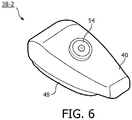
- the capsule member 38 (labeled 38-2 in FIG. 6 ) may have an upper portion 40 that is provided with a filling valve 54 to enable fluid to be added to the reservoir 44 in capsule member 38-2 as needed.
- upper portion 40 may be made from a self-sealing material that self-seals after being punctured with a needle or similar device (which would be used to fill capsule member 38) such as, without limitation, room temperature vulcanizing silicone (RTV), liquid silicone rubber (LSR), thermoplastic elastomer (TPE) or some other suitable, self-sealing elastomer material.
- capsule member 38 may be refilled through the bottom of capsule member 38 using a syringe like device inserted through one of the second openings 31 and one of the first openings 46.
- upper portion 40 may be made of a flexible material, wherein refilling capsule member 38 would involve compressing upper portion 40, placing oral care assembly 30 into fluid, and then releasing upper portion 40 to draw the fluid in through openings 31 and 46.
- the disclosed concept may be employed in connection with an oral care device configured to provide different oral care functionality.
- the oral care assemblies described herein may be provided with bristles that are conventional toothbrush bristles such that the disclosed concept can be implemented in a powered toothbrush device which is able to simultaneously clean teeth and deliver an anti-bacterial fluid to the oral cavity of the user that can be used to reduce malodor and can enhance taste sensitivity.
- any reference signs placed between parentheses shall not be construed as limiting the claim.
- the word “comprising” or “including” does not exclude the presence of elements or steps other than those listed in a claim.
- several of these means may be embodied by one and the same item of hardware.
- the word “a” or “an” preceding an element does not exclude the presence of a plurality of such elements.
- any device claim enumerating several means several of these means may be embodied by one and the same item of hardware.
- the mere fact that certain elements are recited in mutually different dependent claims does not indicate that these elements cannot be used in combination.
Landscapes
- Health & Medical Sciences (AREA)
- Dentistry (AREA)
- Epidemiology (AREA)
- Life Sciences & Earth Sciences (AREA)
- Animal Behavior & Ethology (AREA)
- General Health & Medical Sciences (AREA)
- Public Health (AREA)
- Veterinary Medicine (AREA)
- Brushes (AREA)
- Reciprocating Pumps (AREA)
Description
- The present invention pertains to a powered oral care apparatus, such as, without limitation, a power toothbrush, powered tongue cleaning device (e.g., a tongue scraper or tongue brush), or a powered tooth whitening device, and, in particular, to a powered oral care apparatus having a pump-free fluid delivery system for delivering one or more fluids to the oral cavity of a user.
- There are a variety of oral care devices known in the industry, including manual and powered toothbrushes, tongue cleaning devices, tooth whitening delivery systems, and chemical treatments, such as mouthwashes.
- There is a need for oral care devices that efficiently and effectively combine mechanical action and fluid delivery in a single device. In this respect, it is noted that
US 2013/212823 A1 discloses a toothbrush, comprising a head part with a cleaning structure featuring bristles, a hand part and a neck part, and a cavity located in the head or neck part comprising at least one outlet opening for an active substance. In one embodiment, the cavity incorporates an active substance element, which contains the active substance in a carrier material and releases said substance in a controlled manner when it comes into contact with water. Further,US 2006/165473 A1 discloses an oral care toothbrush which includes a head mounted to one end of the handle containing a plurality of oral care elements. An oral care accessory is mounted to the opposite end of the handle. An oral care material dispenser is mounted in the head within the cleaning field defined by the oral care elements. - According to the invention, a powered oral care apparatus according to appended
claim 1, and an oral care assembly according to appendedclaim 10, are provided. Further embodiments are defined in the appended dependent claims. The powered oral care apparatus further comprises a head assembly having an arm portion, a coupling portion structured to enable the head assembly to be disposed on the driveshaft, and an oral care assembly provided at the distal end of the arm portion. The oral care assembly includes a fluid capsule member structured to hold a fluid, wherein the oral care assembly comprises the fluid capsule member provided on a first side of the distal end of the arm portion, the capsule member including an upper portion and a bottom generally planar wall portion defining a reservoir, the bottom wall portion having a number of first openings provided therethrough, wherein the oral care assembly further comprises an outer wall portion defining a planar wall portion, the planar wall portion having a number of second openings provided therethrough, the first openings being generally aligned with the second openings, and wherein the oral care assembly is structured to dispense the fluid from the reservoir and out of the oral care assembly through the number of first openings and the number of second openings in response to motion imparted by the motor. The oral care assembly is also structured to dispense the fluid from the reservoir and out of the oral care assembly in response to the motion imparted by the motor. - These and other objects, features, and characteristics of the present invention, as well as the methods of operation and functions of the related elements of structure and the combination of parts and economies of manufacture, will become more apparent upon consideration of the following description and the appended claims with reference to the accompanying drawings, all of which form a part of this specification, wherein like reference numerals designate corresponding parts in the various figures. It is to be expressly understood, however, that the drawings are for the purpose of illustration and description only and are not intended as a definition of the limits of the invention.
-
-
FIG. 1 is a view of a powered oral care device according to one exemplary embodiment of the present invention; -
FIGS. 2 and 3 are isometric cross-sectional views of a head assembly forming a part of the powered oral care device ofFIG. 1 according to the non-limiting exemplary embodiment; -
FIG. 4 is a cross-sectional view of an alternative plate member that may be used in the powered oral care device ofFIG. 1 ; and -
FIG. 5 is a bottom plan view of an alternative capsule member; and -
FIG. 6 is an isometric view of another alternative capsule member. - As used herein, the singular form of "a", "an", and "the" include plural references unless the context clearly dictates otherwise. As used herein, the statement that two or more parts or components are "coupled" shall mean that the parts are joined or operate together either directly or indirectly, i.e., through one or more intermediate parts or components, so long as a link occurs. As used herein, "directly coupled" means that two elements are directly in contact with each other. As used herein, "fixedly coupled" or "fixed" means that two components are coupled so as to move as one while maintaining a constant orientation relative to each other.
- As used herein, the word "unitary" means a component is created as a single piece or unit. That is, a component that includes pieces that are created separately and then coupled together as a unit is not a "unitary" component or body. As employed herein, the statement that two or more parts or components "engage" one another shall mean that the parts exert a force against one another either directly or through one or more intermediate parts or components. As employed herein, the term "number" shall mean one or an integer greater than one (i.e., a plurality).
- Directional phrases used herein, such as, for example and without limitation, top, bottom, left, right, upper, lower, front, back, and derivatives thereof, relate to the orientation of the elements shown in the drawings and are not limiting upon the claims unless expressly recited therein.
-
FIG. 1 is a representational view of a poweredoral care device 2 according to one exemplary embodiment of the present invention. As described in greater detail herein,oral care device 2 is, in the illustrated configuration, structured to combine chemical and mechanical oral cleaning methods in a single device by (i) including a head assembly 4 (described below) that may be selectively attached to a handle portion 6 (also described below) for removing debris, plaque, and/or biofilm from the oral cavity of the user (as assisted by the powered movement ofhead assembly 4 as described herein), and (ii) providinghead assembly 4 with a pump-free fluid delivery system for storing and delivering a fluid, such as a tooth cleaning chemistry, mouthwash containing an antibacterial chemical, or tooth whitening chemistry, to the oral cavity of a user. In particular, rather than using motorized pumping for fluid delivery,oral care device 2 uses energy harvested from the powered mechanical motion oforal care device 2 to cause the stored fluid to be delivered to the oral cavity of a user. In addition, as described in greater detail below, in the exemplary embodiment,oral care device 2 is structured in a manner that enables different head assemblies, such as a more conventional power toothbrush assembly, to be selectively attached to thehandle portion 6 as desired. -
Handle portion 6 has anelongated driveshaft 3 extending from the distal end thereof and a battery poweredelectric motor 1 positioned withinhandle portion 6. Removably mounted on thedriveshaft 3 ishead assembly 4. Themotor 1 housed withinhandle portion 6 is structured to movedriveshaft 3, and thushead assembly 4 coupled thereto, in an oscillating manner through a selected angle. Themotor 1 is powered by arechargeable battery 9 and is controlled bycontroller 11 and a user-operated on/offswitch 8 provided onhandle portion 6.Head assembly 4 includes acoupling assembly 10 at a proximal end thereof for attaching to thedrive shaft 3 ofhandle 6 and anarm portion 12 extending betweencoupling assembly 10 andoral care assembly 30 at a distal end thereof. - A number of
bristles 5, form a part of and extend from oral care assembly 30 (described in detail below) at the distal end ofhead assembly 4, and are the primary mechanism for effectuating the mechanical cleaning function oforal care device 2. Also as seen inFIG. 1 ,oral care assembly 30 also includes a number ofsecond openings 31 as described elsewhere herein. - In operation, when the
motor 1 inhandle portion 6 is activated and drivesdriveshaft 3,head assembly 4, and thusoral care assembly 30, is caused to rotate/oscillate back and forth through a selected angle. In the exemplary embodiment,oral care assembly 30 is caused to rotate/oscillate ±5° at 250 Hz. As described in greater detail below, this rotation/oscillation motion simultaneously (i) assists with the mechanical operation of thebristles 5, and (ii) automatically delivers the fluid stored inoral care assembly 30 to the oral cavity of the user. - As seen in
FIGS. 2 and 3 ,oral care assembly 30 includes anouter wall portion 19 which defines anoblong recess 23. Aplanar wall 27 is provided between and withinouter wall 19. Planarwall 27 includes a number ofsecond openings 31 that extend therethrough. Thebristles 5 shown inFIG. 1 are attached to and extend outwardly from the outer surface ofplanar wall 27, with eachsecond opening 31 being positioned adjacent to a number of thebristles 5. - It can be appreciated that the
bristles 5 can be typical toothbrush bristles, or other cleaning mechanisms, such as cone shaped soft elastopolymer structures, or soft foam or sponges, although the term "bristle" as used herein is intended to more broadly encompass all of these mechanisms. Finally,oral care assembly 30 further includes acapsule member 38 that is coupled thereto, oppositeplanar wall 27. Capsulemember 38 is structured to hold a fluid, such as a tooth cleaning chemistry, mouthwash containing an antibacterial chemical, taste enhancing chemistry, or tooth whitening chemistry, and facilitate delivery of the fluid to the oral cavity of the user throughsecond openings 31 during use oforal care device 2. - Capsule
member 38 includes anupper portion 40 coupled to a bottom generallyplanar wall portion 42, which together define areservoir 44 structured to hold the fluid therein.Upper portion 40 may be made from a generally rigid material, such as polypropylene or a similar material, or may alternatively be made from a flexible material, such as silicone rubber. Bottomplanar wall portion 42 has a number offirst openings 46 that extend therethrough. In the exemplary embodiment, eachfirst opening 46 has an oblong, oval-shape, although it will be understood that other shapes are also possible within the scope of the concept disclosed herein. Capsulemember 38 further includes alip member 48 which surrounds bottomplanar wall portion 42.Lip member 48 is structured to be received withinoral care assembly 30. In the illustrated, non-limiting exemplary embodiment, whencapsule member 38 is received in theoral care assembly 30, achamber 50 is formed betweenplanar wall portion 27 and bottomplanar wall portion 42.Chamber 50 is optional, and may be omitted in alternative embodiments. Furthermore, in still another alternative embodiment, a flow regulating member, such as a sponge, may be positioned inchamber 50 to help regulate the flow of fluid fromoral care assembly 30. Alternatively, a flow regulating member, such as a sponge, may be provided as part ofcapsule member 38 within the space defined bylip member 48. In the exemplary embodiment,head assembly 4 is constructed such thatfirst openings 46 will be generally aligned withsecond openings 31 whenoral care assembly 30 is assembled. In the illustrated embodiment,second openings 31 each have a circular shape andfirst openings 46 each have an oblong shape. It will be understood, however, that this is meant to be exemplary only and that other shapes are also possible within the scope of the concept disclosed herein. - In the exemplary embodiment, bristles 5 are structured to exhibit hydrophobic behavior such that when
capsule member 38 is coupled intooral care assembly 30, the fluid will remain withincapsule member 38 even whenhead assembly 4 is positioned as shown inFIG. 2 . This is accomplished by the material ofbristles 5, and any surface coating or treatment thereon. In one embodiment, bristles 5 may be made from polydimethylsiloxane (PDMS), which is naturally hydrophobic. Also, the size ofsecond openings 31 helps determine how difficult it is for the fluid to be released. - In operation, a user inserts the distal end of
head assembly 4 includingoral care assembly 30 into his or her mouth and turns onmotor 1 ofhandle portion 6 using on/offswitch 8. As elsewhere described herein, the operation ofmotor 1 causeshead assembly 4, and in particularoral care assembly 30, to rotate/oscillate back and forth over a predetermined angle. The user may then use theoral care assembly 30, and inparticular bristles 5 thereof, to clean surfaces within the oral cavity, or apply chemicals in theoral care assembly 30 to one or more surfaces within the oral cavity. For example, iforal care device 2 is a tongue cleaning device, the rotating/oscillating movement oforal care assembly 30 facilitates a scraping function to remove biofilm from the surface of the tongue and deliver chemistry that will help reduce malodor and can enhance taste sensitivity of the user. In addition, the rotating/oscillating movement oforal care assembly 30 will generate a centrifugal force that will cause the fluid stored incapsule member 38 to be delivered in a controlled manner throughfirst openings 46 of bottomplanar wall portion 42,chamber 50, andsecond openings 31 andpast bristles 5 into the oral cavity of the user where it can be delivered to the appropriate surface therein. Thus, in this pump free arrangement, the pumping function is automatically performed by forces generated by the motion. - In various alternative embodiments, the number of
openings openings oral care assembly 30 as desired. - In another example, the oral care assemblies described herein may be implemented in a device for delivering a whitening solution to the teeth of a user. In such an implementation, as shown in
FIG. 4 thebristles 5 described herein may be replaced with an alternative structure, such as anapplicator pad 92 havingholes 94 aligned withsecond openings 31 in an alternativeplanar wall 27, that would facilitate the application of the whitening solution to the user's teeth. - In one exemplary embodiment,
capsule member 38 is a replaceable element as shown inFIG. 5 (labelled 38-1) that is structured to be selectively snap fit ontooral care assembly 30 and be replaced as needed. As seen inFIG. 5 , this embodiment ofcapsule member 38 includes a sealingmember 52 that is sealingly and removably attached tolip member 48 in order to contain the fluid within capsule member 38-1 until it is to be attached tooral care assembly 30. In the exemplary embodiment, sealingmember 52 is made from a metallic film material that is releasably attached tolip member 48, although it will be appreciated that other configurations are also possible. When capsule member 38-1 is to be attached, sealingmember 52 is removed or punctured and capsule member 38-1 is coupled to theoral care assembly 30 by inserting and snapfitting lip member 48 intorecess 23 as seen inFIG. 3 so that the fluid inreservoir 44 can be delivered as described above. In such a configuration, capsule member 38-1 is friction fit tooral care assembly 30 so thatoral care device 2 may be used as described above. When all of the fluid within thereservoir 44 has been dispensed, capsule 38-1 may be removed and replaced with another similarly structured capsule member 38-1. - In another alternative exemplary embodiment,
capsule member 38 is removably or permanently affixed to theoral care assembly 30 and is structured to be refillable with fluid as needed. For example, as shown inFIG. 6 , the capsule member 38 (labeled 38-2 inFIG. 6 ) may have anupper portion 40 that is provided with a fillingvalve 54 to enable fluid to be added to thereservoir 44 in capsule member 38-2 as needed. As another example,upper portion 40 may be made from a self-sealing material that self-seals after being punctured with a needle or similar device (which would be used to fill capsule member 38) such as, without limitation, room temperature vulcanizing silicone (RTV), liquid silicone rubber (LSR), thermoplastic elastomer (TPE) or some other suitable, self-sealing elastomer material. As still another example,capsule member 38 may be refilled through the bottom ofcapsule member 38 using a syringe like device inserted through one of thesecond openings 31 and one of thefirst openings 46. As yet another example,upper portion 40 may be made of a flexible material, wherein refillingcapsule member 38 would involve compressingupper portion 40, placingoral care assembly 30 into fluid, and then releasingupper portion 40 to draw the fluid in throughopenings - It will be understood that that the disclosed concept may be employed in connection with an oral care device configured to provide different oral care functionality. For example, the oral care assemblies described herein may be provided with bristles that are conventional toothbrush bristles such that the disclosed concept can be implemented in a powered toothbrush device which is able to simultaneously clean teeth and deliver an anti-bacterial fluid to the oral cavity of the user that can be used to reduce malodor and can enhance taste sensitivity.
- In the claims, any reference signs placed between parentheses shall not be construed as limiting the claim. The word "comprising" or "including" does not exclude the presence of elements or steps other than those listed in a claim. In a device claim enumerating several means, several of these means may be embodied by one and the same item of hardware. The word "a" or "an" preceding an element does not exclude the presence of a plurality of such elements. In any device claim enumerating several means, several of these means may be embodied by one and the same item of hardware. The mere fact that certain elements are recited in mutually different dependent claims does not indicate that these elements cannot be used in combination.
- Although the invention has been described in detail for the purpose of illustration based on what is currently considered to be the most practical and preferred embodiments, it is to be understood that such detail is solely for that purpose and that the invention is not limited to the disclosed embodiments, but, on the contrary, is intended to cover modifications and equivalent arrangements that are within the scope of the appended claims. For example, it is to be understood that the present invention contemplates that, to the extent possible, one or more features of any embodiment can be combined with one or more features of any other embodiment.
Claims (15)
- A powered oral care apparatus (2) comprising:a handle (6) having a motor (1) and a driveshaft (3) coupled to the motor (1);a head assembly (4) having an arm portion (12), a coupling portion (10) structured to enable the head assembly (4) to be disposed on the driveshaft (3), and an oral care assembly (30) provided at a distal end of the arm portion (12), wherein the oral care assembly (30) includes a fluid capsule member (38) structured to hold a fluid, wherein the oral care assembly (30) comprises the fluid capsule member (38) provided on a first side of the distal end of the arm portion (12), the capsule member (38) including an upper portion (40) and a bottom generally planar wall portion (42) defining a reservoir (44), the bottom wall portion (42) having a number of first openings (46) provided therethrough, wherein the oral care assembly (30) further comprises an outer wall portion (19) defining a planar wall portion (27), the planar wall portion (27) having a number of second openings (31) provided therethrough, the first openings (46) being generally aligned with the second openings (31), and wherein the oral care assembly (30) is structured to dispense the fluid from the reservoir (44) and out of the oral care assembly (30) through the number of first openings (46) and the number of second openings (31) in response to motion imparted by the motor (1).
- The powered oral care apparatus (2) according to claim 1, wherein the fluid capsule member (38) further includes a lip member (48) coupled to the bottom planar wall portion (42), the lip member (48) being structured to be received within a recess (23) provided in the oral care assembly (30).
- The powered oral care assembly (2) according to claim 2, wherein a flow regulating member is provided as part of the capsule member (38) within the space defined by the lip member (48).
- The powered oral care apparatus (2) according to claim 2, wherein the fluid capsule member (38) is structured to be removably coupled to the oral care assembly (30).
- The powered oral care apparatus (2) according to claim 1, wherein, when the capsule member (38) is received in the oral care assembly (30), a chamber (50) is formed between the planar wall portion (27) and the bottom planar wall portion (42).
- The powered oral care apparatus (2) according to claim 5, wherein a flow regulating member is positioned in the chamber (50) to help regulate the flow of fluid from the oral care assembly (30).
- The powered oral care apparatus (2) according to claim 1, wherein the planar wall portion (27) includes a number of bristles (5) attached to and extending outwardly from an outer surface thereof.
- The powered oral care apparatus (2) according to claim 7, wherein the bristles (5) are structured to exhibit hydrophobic behavior.
- The powered oral care apparatus (2) according to claim 1, wherein the upper portion (40) of the capsule member (38) includes a valve member (54) for refilling the reservoir (44).
- An oral care assembly (30) for an oral care apparatus (2) having a handle (6) having a motor (1) and a driveshaft (3) coupled to the motor (1), and a head assembly (4) coupled to the handle (6); wherein the oral care assembly (30) is structured to be coupled to a distal end of the head assembly (4);
the oral care assembly (30) comprising an outer wall portion (19) defining a planar wall portion (27), the planar wall portion (27) having a number of second openings (31) provided therethrough, and a fluid capsule member (38) comprising an upper portion (40); and a bottom generally planar wall portion (42) coupled to the upper portion (40), the bottom wall portion (42) having a number of first openings (46) provided therethrough, the first openings (46) being generally aligned with the second openings (31), wherein the upper portion (40) and the bottom wall portion (42) define a reservoir (44) for holding a fluid, and wherein the fluid capsule member (38) is structured to dispense the fluid from the reservoir (44) through the number of first openings (46) and the number of second openings (31) in response to motion imparted by the motor (1) of the oral care apparatus (2) when the head assembly (4) is disposed on the driveshaft (3). - The oral care assembly (30) according to claim 10, further comprising a lip member (48) coupled to the bottom planar wall portion (42), the lip member (48) being structured to be received within a recess (23) provided in the oral care assembly (30).
- The oral care assembly (30) according to claim 11, wherein a flow regulating member is provided as part of the capsule member (38) within the space defined by the lip member (48).
- The oral care assembly (30) according to claim 11, wherein the fluid capsule member (38) is structured to be removably coupled to the oral care assembly (30).
- The oral care assembly (30) according to claim 10, wherein, when the capsule member (38) is received in the oral care assembly (30), a chamber (50) is formed between the planar wall portion (27) and the bottom planar wall portion (42).
- The oral care assembly (30) according to claim 14, wherein a flow regulating member is positioned in the chamber (50) to help regulate the flow of fluid from the oral care assembly (30).
Applications Claiming Priority (2)
| Application Number | Priority Date | Filing Date | Title |
|---|---|---|---|
| US201462056662P | 2014-09-29 | 2014-09-29 | |
| PCT/IB2015/053704 WO2016051287A1 (en) | 2014-09-29 | 2015-05-20 | Oral care device having a pump-free fluid delivery system |
Publications (2)
| Publication Number | Publication Date |
|---|---|
| EP3200651A1 EP3200651A1 (en) | 2017-08-09 |
| EP3200651B1 true EP3200651B1 (en) | 2019-03-20 |
Family
ID=53490011
Family Applications (1)
| Application Number | Title | Priority Date | Filing Date |
|---|---|---|---|
| EP15732050.8A Active EP3200651B1 (en) | 2014-09-29 | 2015-05-20 | Oral care device having a pump-free fluid delivery system |
Country Status (7)
| Country | Link |
|---|---|
| US (1) | US10448729B2 (en) |
| EP (1) | EP3200651B1 (en) |
| JP (1) | JP6717809B2 (en) |
| CN (1) | CN106794057B (en) |
| RU (1) | RU2689066C2 (en) |
| TR (1) | TR201906698T4 (en) |
| WO (1) | WO2016051287A1 (en) |
Families Citing this family (2)
| Publication number | Priority date | Publication date | Assignee | Title |
|---|---|---|---|---|
| JP6700394B2 (en) | 2015-12-15 | 2020-05-27 | コーニンクレッカ フィリップス エヌ ヴェKoninklijke Philips N.V. | Attachment assembly for an oral hygiene device with improved fluid chamber, fluid channel, fluid outlet hole, air inlet hole and air channel features |
| CN115349972B (en) * | 2022-08-05 | 2024-02-02 | 深圳素士科技股份有限公司 | Integrated oral care device |
Family Cites Families (12)
| Publication number | Priority date | Publication date | Assignee | Title |
|---|---|---|---|---|
| BE894029A (en) | 1982-08-04 | 1982-12-01 | Laureys Willy | Disposable tooth-brush bristle head - contg. tooth-paste-filled cavity with openings to bristle area and pref. flexible foil-covered |
| EP0332026B1 (en) * | 1988-03-08 | 1993-07-14 | Colgate-Palmolive Company | Tootbrush with slow release of disinfectant and anti-bacterial agents and method of manufacturing the same |
| EP0565598B1 (en) * | 1990-12-13 | 1998-04-15 | Gemtech, Inc. | Dentifrice-medication dispensing toothbrush |
| CN2358849Y (en) | 1998-12-31 | 2000-01-19 | 邓时武 | Electric toothbrush with shield |
| DE19949671A1 (en) * | 1999-10-14 | 2001-04-19 | Coronet Werke Gmbh | Brush, especially toothbrush |
| US7478959B2 (en) | 2002-09-05 | 2009-01-20 | Colgate-Palmolive Company | Oral care toothbrush |
| JP2004121327A (en) * | 2002-09-30 | 2004-04-22 | Keitouuwai Project:Kk | Treatment probe |
| US7934284B2 (en) | 2003-02-11 | 2011-05-03 | Braun Gmbh | Toothbrushes |
| EP1639913B1 (en) | 2004-09-22 | 2011-11-23 | Trisa Holding AG | Brush, in particular toothbrush and method of making thereof |
| US8517728B2 (en) | 2007-01-24 | 2013-08-27 | Colgate-Palmolive Company | Oral care implement having fluid delivery system |
| US8459892B2 (en) | 2008-06-25 | 2013-06-11 | Colgate-Palmolive Company | Oral care implement |
| WO2012087332A1 (en) | 2010-12-23 | 2012-06-28 | California Institute Of Technology | Systems and methods for remote long standoff biometric identification using microwave cardiac signals |
-
2015
- 2015-05-20 RU RU2017115068A patent/RU2689066C2/en active
- 2015-05-20 EP EP15732050.8A patent/EP3200651B1/en active Active
- 2015-05-20 CN CN201580052561.9A patent/CN106794057B/en active Active
- 2015-05-20 TR TR2019/06698T patent/TR201906698T4/en unknown
- 2015-05-20 JP JP2017516321A patent/JP6717809B2/en active Active
- 2015-05-20 WO PCT/IB2015/053704 patent/WO2016051287A1/en active Application Filing
- 2015-05-20 US US15/515,005 patent/US10448729B2/en active Active
Non-Patent Citations (1)
| Title |
|---|
| None * |
Also Published As
| Publication number | Publication date |
|---|---|
| CN106794057B (en) | 2020-07-03 |
| TR201906698T4 (en) | 2019-05-21 |
| US20170215569A1 (en) | 2017-08-03 |
| CN106794057A (en) | 2017-05-31 |
| EP3200651A1 (en) | 2017-08-09 |
| RU2017115068A3 (en) | 2019-03-26 |
| US10448729B2 (en) | 2019-10-22 |
| WO2016051287A1 (en) | 2016-04-07 |
| RU2017115068A (en) | 2018-11-05 |
| JP6717809B2 (en) | 2020-07-08 |
| JP2017528272A (en) | 2017-09-28 |
| RU2689066C2 (en) | 2019-05-23 |
Similar Documents
| Publication | Publication Date | Title |
|---|---|---|
| US8444416B2 (en) | Valves for personal care devices | |
| US7503715B2 (en) | Soap dispensing attachment for hand-held appliance | |
| US5573020A (en) | Dental flossing device and method therefor | |
| KR20140105844A (en) | Oral care implement | |
| JP5606328B2 (en) | Oral care toothbrush | |
| ES2331858T3 (en) | DEVICE FOR DISPENSING A FLUID AND MASSAGE. | |
| JP2017500956A (en) | Fluid dispensing device for personal care devices | |
| JP7105931B2 (en) | dental care appliances | |
| TW201442667A (en) | Oral care system | |
| EP3200651B1 (en) | Oral care device having a pump-free fluid delivery system | |
| TW201440689A (en) | Oral care dispenser | |
| JP7191129B2 (en) | dental care appliance | |
| CN112334088A (en) | Tooth treatment appliance | |
| US10022203B2 (en) | Handpiece for endodontic treatment | |
| WO2020016547A1 (en) | Dental treatment appliance | |
| US20210353042A1 (en) | Skin treatment head with integrated release system |
Legal Events
| Date | Code | Title | Description |
|---|---|---|---|
| STAA | Information on the status of an ep patent application or granted ep patent |
Free format text: STATUS: THE INTERNATIONAL PUBLICATION HAS BEEN MADE |
|
| PUAI | Public reference made under article 153(3) epc to a published international application that has entered the european phase |
Free format text: ORIGINAL CODE: 0009012 |
|
| STAA | Information on the status of an ep patent application or granted ep patent |
Free format text: STATUS: REQUEST FOR EXAMINATION WAS MADE |
|
| 17P | Request for examination filed |
Effective date: 20170502 |
|
| AK | Designated contracting states |
Kind code of ref document: A1 Designated state(s): AL AT BE BG CH CY CZ DE DK EE ES FI FR GB GR HR HU IE IS IT LI LT LU LV MC MK MT NL NO PL PT RO RS SE SI SK SM TR |
|
| AX | Request for extension of the european patent |
Extension state: BA ME |
|
| DAV | Request for validation of the european patent (deleted) | ||
| DAX | Request for extension of the european patent (deleted) | ||
| GRAP | Despatch of communication of intention to grant a patent |
Free format text: ORIGINAL CODE: EPIDOSNIGR1 |
|
| STAA | Information on the status of an ep patent application or granted ep patent |
Free format text: STATUS: GRANT OF PATENT IS INTENDED |
|
| INTG | Intention to grant announced |
Effective date: 20180928 |
|
| RIN1 | Information on inventor provided before grant (corrected) |
Inventor name: EDWARDS, MARTIN JOHN Inventor name: SPRUIT, JOHANNES HENDRIKUS MARIA Inventor name: DEANE, STEVEN CHARLES |
|
| GRAS | Grant fee paid |
Free format text: ORIGINAL CODE: EPIDOSNIGR3 |
|
| GRAA | (expected) grant |
Free format text: ORIGINAL CODE: 0009210 |
|
| STAA | Information on the status of an ep patent application or granted ep patent |
Free format text: STATUS: THE PATENT HAS BEEN GRANTED |
|
| AK | Designated contracting states |
Kind code of ref document: B1 Designated state(s): AL AT BE BG CH CY CZ DE DK EE ES FI FR GB GR HR HU IE IS IT LI LT LU LV MC MK MT NL NO PL PT RO RS SE SI SK SM TR |
|
| REG | Reference to a national code |
Ref country code: GB Ref legal event code: FG4D |
|
| REG | Reference to a national code |
Ref country code: CH Ref legal event code: EP |
|
| REG | Reference to a national code |
Ref country code: DE Ref legal event code: R096 Ref document number: 602015026749 Country of ref document: DE |
|
| REG | Reference to a national code |
Ref country code: AT Ref legal event code: REF Ref document number: 1109586 Country of ref document: AT Kind code of ref document: T Effective date: 20190415 |
|
| REG | Reference to a national code |
Ref country code: IE Ref legal event code: FG4D |
|
| REG | Reference to a national code |
Ref country code: NL Ref legal event code: MP Effective date: 20190320 |
|
| PG25 | Lapsed in a contracting state [announced via postgrant information from national office to epo] |
Ref country code: LT Free format text: LAPSE BECAUSE OF FAILURE TO SUBMIT A TRANSLATION OF THE DESCRIPTION OR TO PAY THE FEE WITHIN THE PRESCRIBED TIME-LIMIT Effective date: 20190320 Ref country code: SE Free format text: LAPSE BECAUSE OF FAILURE TO SUBMIT A TRANSLATION OF THE DESCRIPTION OR TO PAY THE FEE WITHIN THE PRESCRIBED TIME-LIMIT Effective date: 20190320 Ref country code: FI Free format text: LAPSE BECAUSE OF FAILURE TO SUBMIT A TRANSLATION OF THE DESCRIPTION OR TO PAY THE FEE WITHIN THE PRESCRIBED TIME-LIMIT Effective date: 20190320 Ref country code: NO Free format text: LAPSE BECAUSE OF FAILURE TO SUBMIT A TRANSLATION OF THE DESCRIPTION OR TO PAY THE FEE WITHIN THE PRESCRIBED TIME-LIMIT Effective date: 20190620 |
|
| REG | Reference to a national code |
Ref country code: LT Ref legal event code: MG4D |
|
| PG25 | Lapsed in a contracting state [announced via postgrant information from national office to epo] |
Ref country code: LV Free format text: LAPSE BECAUSE OF FAILURE TO SUBMIT A TRANSLATION OF THE DESCRIPTION OR TO PAY THE FEE WITHIN THE PRESCRIBED TIME-LIMIT Effective date: 20190320 Ref country code: GR Free format text: LAPSE BECAUSE OF FAILURE TO SUBMIT A TRANSLATION OF THE DESCRIPTION OR TO PAY THE FEE WITHIN THE PRESCRIBED TIME-LIMIT Effective date: 20190621 Ref country code: HR Free format text: LAPSE BECAUSE OF FAILURE TO SUBMIT A TRANSLATION OF THE DESCRIPTION OR TO PAY THE FEE WITHIN THE PRESCRIBED TIME-LIMIT Effective date: 20190320 Ref country code: RS Free format text: LAPSE BECAUSE OF FAILURE TO SUBMIT A TRANSLATION OF THE DESCRIPTION OR TO PAY THE FEE WITHIN THE PRESCRIBED TIME-LIMIT Effective date: 20190320 Ref country code: NL Free format text: LAPSE BECAUSE OF FAILURE TO SUBMIT A TRANSLATION OF THE DESCRIPTION OR TO PAY THE FEE WITHIN THE PRESCRIBED TIME-LIMIT Effective date: 20190320 Ref country code: BG Free format text: LAPSE BECAUSE OF FAILURE TO SUBMIT A TRANSLATION OF THE DESCRIPTION OR TO PAY THE FEE WITHIN THE PRESCRIBED TIME-LIMIT Effective date: 20190620 |
|
| REG | Reference to a national code |
Ref country code: AT Ref legal event code: MK05 Ref document number: 1109586 Country of ref document: AT Kind code of ref document: T Effective date: 20190320 |
|
| PG25 | Lapsed in a contracting state [announced via postgrant information from national office to epo] |
Ref country code: PT Free format text: LAPSE BECAUSE OF FAILURE TO SUBMIT A TRANSLATION OF THE DESCRIPTION OR TO PAY THE FEE WITHIN THE PRESCRIBED TIME-LIMIT Effective date: 20190720 Ref country code: ES Free format text: LAPSE BECAUSE OF FAILURE TO SUBMIT A TRANSLATION OF THE DESCRIPTION OR TO PAY THE FEE WITHIN THE PRESCRIBED TIME-LIMIT Effective date: 20190320 Ref country code: CZ Free format text: LAPSE BECAUSE OF FAILURE TO SUBMIT A TRANSLATION OF THE DESCRIPTION OR TO PAY THE FEE WITHIN THE PRESCRIBED TIME-LIMIT Effective date: 20190320 Ref country code: RO Free format text: LAPSE BECAUSE OF FAILURE TO SUBMIT A TRANSLATION OF THE DESCRIPTION OR TO PAY THE FEE WITHIN THE PRESCRIBED TIME-LIMIT Effective date: 20190320 Ref country code: EE Free format text: LAPSE BECAUSE OF FAILURE TO SUBMIT A TRANSLATION OF THE DESCRIPTION OR TO PAY THE FEE WITHIN THE PRESCRIBED TIME-LIMIT Effective date: 20190320 Ref country code: IT Free format text: LAPSE BECAUSE OF FAILURE TO SUBMIT A TRANSLATION OF THE DESCRIPTION OR TO PAY THE FEE WITHIN THE PRESCRIBED TIME-LIMIT Effective date: 20190320 Ref country code: SK Free format text: LAPSE BECAUSE OF FAILURE TO SUBMIT A TRANSLATION OF THE DESCRIPTION OR TO PAY THE FEE WITHIN THE PRESCRIBED TIME-LIMIT Effective date: 20190320 Ref country code: AL Free format text: LAPSE BECAUSE OF FAILURE TO SUBMIT A TRANSLATION OF THE DESCRIPTION OR TO PAY THE FEE WITHIN THE PRESCRIBED TIME-LIMIT Effective date: 20190320 |
|
| PG25 | Lapsed in a contracting state [announced via postgrant information from national office to epo] |
Ref country code: PL Free format text: LAPSE BECAUSE OF FAILURE TO SUBMIT A TRANSLATION OF THE DESCRIPTION OR TO PAY THE FEE WITHIN THE PRESCRIBED TIME-LIMIT Effective date: 20190320 Ref country code: SM Free format text: LAPSE BECAUSE OF FAILURE TO SUBMIT A TRANSLATION OF THE DESCRIPTION OR TO PAY THE FEE WITHIN THE PRESCRIBED TIME-LIMIT Effective date: 20190320 |
|
| REG | Reference to a national code |
Ref country code: CH Ref legal event code: PL |
|
| PG25 | Lapsed in a contracting state [announced via postgrant information from national office to epo] |
Ref country code: AT Free format text: LAPSE BECAUSE OF FAILURE TO SUBMIT A TRANSLATION OF THE DESCRIPTION OR TO PAY THE FEE WITHIN THE PRESCRIBED TIME-LIMIT Effective date: 20190320 Ref country code: IS Free format text: LAPSE BECAUSE OF FAILURE TO SUBMIT A TRANSLATION OF THE DESCRIPTION OR TO PAY THE FEE WITHIN THE PRESCRIBED TIME-LIMIT Effective date: 20190720 |
|
| REG | Reference to a national code |
Ref country code: DE Ref legal event code: R097 Ref document number: 602015026749 Country of ref document: DE |
|
| PLBE | No opposition filed within time limit |
Free format text: ORIGINAL CODE: 0009261 |
|
| STAA | Information on the status of an ep patent application or granted ep patent |
Free format text: STATUS: NO OPPOSITION FILED WITHIN TIME LIMIT |
|
| PG25 | Lapsed in a contracting state [announced via postgrant information from national office to epo] |
Ref country code: MC Free format text: LAPSE BECAUSE OF FAILURE TO SUBMIT A TRANSLATION OF THE DESCRIPTION OR TO PAY THE FEE WITHIN THE PRESCRIBED TIME-LIMIT Effective date: 20190320 Ref country code: CH Free format text: LAPSE BECAUSE OF NON-PAYMENT OF DUE FEES Effective date: 20190531 Ref country code: LI Free format text: LAPSE BECAUSE OF NON-PAYMENT OF DUE FEES Effective date: 20190531 Ref country code: DK Free format text: LAPSE BECAUSE OF FAILURE TO SUBMIT A TRANSLATION OF THE DESCRIPTION OR TO PAY THE FEE WITHIN THE PRESCRIBED TIME-LIMIT Effective date: 20190320 |
|
| REG | Reference to a national code |
Ref country code: BE Ref legal event code: MM Effective date: 20190531 |
|
| 26N | No opposition filed |
Effective date: 20200102 |
|
| PG25 | Lapsed in a contracting state [announced via postgrant information from national office to epo] |
Ref country code: SI Free format text: LAPSE BECAUSE OF FAILURE TO SUBMIT A TRANSLATION OF THE DESCRIPTION OR TO PAY THE FEE WITHIN THE PRESCRIBED TIME-LIMIT Effective date: 20190320 Ref country code: LU Free format text: LAPSE BECAUSE OF NON-PAYMENT OF DUE FEES Effective date: 20190520 |
|
| PG25 | Lapsed in a contracting state [announced via postgrant information from national office to epo] |
Ref country code: IE Free format text: LAPSE BECAUSE OF NON-PAYMENT OF DUE FEES Effective date: 20190520 |
|
| PG25 | Lapsed in a contracting state [announced via postgrant information from national office to epo] |
Ref country code: BE Free format text: LAPSE BECAUSE OF NON-PAYMENT OF DUE FEES Effective date: 20190531 |
|
| PG25 | Lapsed in a contracting state [announced via postgrant information from national office to epo] |
Ref country code: CY Free format text: LAPSE BECAUSE OF FAILURE TO SUBMIT A TRANSLATION OF THE DESCRIPTION OR TO PAY THE FEE WITHIN THE PRESCRIBED TIME-LIMIT Effective date: 20190320 |
|
| PG25 | Lapsed in a contracting state [announced via postgrant information from national office to epo] |
Ref country code: HU Free format text: LAPSE BECAUSE OF FAILURE TO SUBMIT A TRANSLATION OF THE DESCRIPTION OR TO PAY THE FEE WITHIN THE PRESCRIBED TIME-LIMIT; INVALID AB INITIO Effective date: 20150520 Ref country code: MT Free format text: LAPSE BECAUSE OF FAILURE TO SUBMIT A TRANSLATION OF THE DESCRIPTION OR TO PAY THE FEE WITHIN THE PRESCRIBED TIME-LIMIT Effective date: 20190320 |
|
| PG25 | Lapsed in a contracting state [announced via postgrant information from national office to epo] |
Ref country code: MK Free format text: LAPSE BECAUSE OF FAILURE TO SUBMIT A TRANSLATION OF THE DESCRIPTION OR TO PAY THE FEE WITHIN THE PRESCRIBED TIME-LIMIT Effective date: 20190320 |
|
| PGFP | Annual fee paid to national office [announced via postgrant information from national office to epo] |
Ref country code: TR Payment date: 20220509 Year of fee payment: 8 |
|
| PGFP | Annual fee paid to national office [announced via postgrant information from national office to epo] |
Ref country code: GB Payment date: 20240521 Year of fee payment: 10 |
|
| PGFP | Annual fee paid to national office [announced via postgrant information from national office to epo] |
Ref country code: DE Payment date: 20240529 Year of fee payment: 10 |
|
| PGFP | Annual fee paid to national office [announced via postgrant information from national office to epo] |
Ref country code: FR Payment date: 20240527 Year of fee payment: 10 |