EP3838185A1 - Reload assembly with knife carrier lockout - Google Patents
Reload assembly with knife carrier lockout Download PDFInfo
- Publication number
- EP3838185A1 EP3838185A1 EP20214062.0A EP20214062A EP3838185A1 EP 3838185 A1 EP3838185 A1 EP 3838185A1 EP 20214062 A EP20214062 A EP 20214062A EP 3838185 A1 EP3838185 A1 EP 3838185A1
- Authority
- EP
- European Patent Office
- Prior art keywords
- knife carrier
- detent
- knife
- retracted position
- supported
- Prior art date
- Legal status (The legal status is an assumption and is not a legal conclusion. Google has not performed a legal analysis and makes no representation as to the accuracy of the status listed.)
- Granted
Links
Images






Classifications
-
- A—HUMAN NECESSITIES
- A61—MEDICAL OR VETERINARY SCIENCE; HYGIENE
- A61B—DIAGNOSIS; SURGERY; IDENTIFICATION
- A61B17/00—Surgical instruments, devices or methods
- A61B17/11—Surgical instruments, devices or methods for performing anastomosis; Buttons for anastomosis
- A61B17/115—Staplers for performing anastomosis, e.g. in a single operation
- A61B17/1155—Circular staplers comprising a plurality of staples
-
- A—HUMAN NECESSITIES
- A61—MEDICAL OR VETERINARY SCIENCE; HYGIENE
- A61B—DIAGNOSIS; SURGERY; IDENTIFICATION
- A61B17/00—Surgical instruments, devices or methods
- A61B17/068—Surgical staplers, e.g. containing multiple staples or clamps
- A61B17/072—Surgical staplers, e.g. containing multiple staples or clamps for applying a row of staples in a single action, e.g. the staples being applied simultaneously
- A61B17/07207—Surgical staplers, e.g. containing multiple staples or clamps for applying a row of staples in a single action, e.g. the staples being applied simultaneously the staples being applied sequentially
-
- A—HUMAN NECESSITIES
- A61—MEDICAL OR VETERINARY SCIENCE; HYGIENE
- A61B—DIAGNOSIS; SURGERY; IDENTIFICATION
- A61B17/00—Surgical instruments, devices or methods
- A61B17/11—Surgical instruments, devices or methods for performing anastomosis; Buttons for anastomosis
-
- A—HUMAN NECESSITIES
- A61—MEDICAL OR VETERINARY SCIENCE; HYGIENE
- A61B—DIAGNOSIS; SURGERY; IDENTIFICATION
- A61B17/00—Surgical instruments, devices or methods
- A61B17/068—Surgical staplers, e.g. containing multiple staples or clamps
- A61B17/072—Surgical staplers, e.g. containing multiple staples or clamps for applying a row of staples in a single action, e.g. the staples being applied simultaneously
- A61B2017/07214—Stapler heads
- A61B2017/07271—Stapler heads characterised by its cartridge
-
- A—HUMAN NECESSITIES
- A61—MEDICAL OR VETERINARY SCIENCE; HYGIENE
- A61B—DIAGNOSIS; SURGERY; IDENTIFICATION
- A61B90/00—Instruments, implements or accessories specially adapted for surgery or diagnosis and not covered by any of the groups A61B1/00 - A61B50/00, e.g. for luxation treatment or for protecting wound edges
- A61B90/08—Accessories or related features not otherwise provided for
- A61B2090/0814—Preventing re-use
Definitions
- the disclosure is directed to circular stapling devices and, more particularly, to reload assemblies for circular stapling devices with structure to retain a knife carrier of the reload assembly in a retracted position after the stapling device is fired.
- Conventional circular stapling devices include an elongate body and a shell or reload assembly that is supported on a distal portion of the elongate body.
- the reload assembly includes a shell housing, a staple cartridge having a plurality of staples supported on the shell housing, a pusher assembly, a knife defining a cylindrical cavity, and a knife carrier that supports the knife.
- the pusher assembly includes an annular pusher and a staple pushing member that is engaged with the annular pusher and is movable to move the staple pushing member to eject staples from the staple cartridge.
- the knife carrier is movable to advance the knife through the staple cartridge to core or cut tissue.
- the knife carrier and the knife are retracted to withdraw the knife into the shell housing.
- the second purpose is to position the knife in a location recessed within the shell housing to avoid injury to a clinician during manipulation and disposal of the reload assembly.
- tissue donut is compressed within the cavity defined by the knife to such a degree that removal of the tissue donut from within the cavity defined by the knife is difficult. Removal of the tissue donut under such circumstances has a tendency to pull the knife from within the shell housing.
- the adaptor assembly has a proximal end portion and a distal end portion.
- the reload assembly is supported on the distal end portion of the adaptor assembly and includes a shell housing, an auxiliary detent, a staple cartridge, a staple pusher, a knife carrier, and a knife.
- the shell housing includes an outer housing portion and an inner housing portion that define an annular cavity.
- the auxiliary detent is supported within the shell housing.
- the staple cartridge is secured to the shell housing and supports a plurality of staples.
- the staple pusher defines a through bore, is supported within the annular cavity of the shell housing, and is movable from a retracted position to an advanced position to eject staples from the staple cartridge.
- the knife carrier is supported within the through bore of the staple pusher, defines a central bore that receives the inner housing portion of the shell housing, and is movable about the inner housing portion between a retracted position and an advanced position.
- the knife carrier defines a pocket that receives the auxiliary detent when the knife carrier is in the retracted position to obstruct movement of the knife carrier from the retracted position towards the advanced position.
- An annular knife is supported on the knife carrier.
- a reload assembly including a shell housing, an auxiliary detent, a staple cartridge, a staple pusher, a knife carrier, and an annular knife.
- the shell housing includes an outer housing portion and an inner housing portion that define an annular cavity.
- the auxiliary detent is supported within the shell housing.
- the staple cartridge is secured to the shell housing and supports a plurality of staples.
- the staple pusher defines a through bore, is supported within the annular cavity, and is movable from a retracted position to an advanced position to eject staples from the staple cartridge.
- the knife carrier is supported within the through bore of the staple pusher, defines a central bore that receives the inner housing portion of the shell housing, and is movable about the inner housing portion of the shell housing between a retracted position and an advanced position.
- the knife carrier defines a pocket that receives the auxiliary detent when the knife carrier is in the retracted position to obstruct movement of the knife carrier from the retracted position towards the advanced position.
- the knife is supported on the knife carrier.
- the stapling device includes a handle assembly having a proximal end portion and a distal end portion.
- the proximal end portion of the adaptor assembly is supported on the handle assembly.
- the auxiliary detent is longitudinally fixed to the shell housing.
- the auxiliary detent is resilient.
- the auxiliary detent is rigid.
- the knife carrier includes an inner surface that defines the central bore of the knife carrier and supports at least one primary detent
- the inner housing portion of the shell housing includes an outer surface that defines at least one longitudinal recess.
- the at least one longitudinal recess receives the at least one primary detent.
- the at least one primary detent has a proximal portion, a distal portion, and an abutment surface that separates the proximal portion of the at least one recess from the distal portion of the at least one recess.
- the at least one primary detent moves into an interference fit with the abutment surface as the knife carrier is moved from its retracted position towards it advanced position.
- a staple actuator is supported within the annular cavity in abutting relation to the staple pusher and is movable from a retracted position to an advanced position to move the staple pusher from its retracted position to its advanced position.
- the auxiliary detent is in the form of a spring clip.
- the knife carrier includes a plurality of resilient longitudinal body portions that define the central bore, wherein each of the longitudinal body portions is spaced from adjacent longitudinal body portions to define longitudinal slots.
- the pocket is defined in adjacent longitudinal body portions of the knife carrier and communicates with a respective one of the longitudinal slots such that the auxiliary detent is aligned with the respective one of the longitudinal slots, wherein the auxiliary detent is movable into the respective one of the longitudinal slots as the knife carrier moves from its retracted position towards its advanced position.
- the adaptor assembly includes a knife driver that is adapted to be releasably coupled to the knife carrier.
- the width of the auxiliary detent is greater than the width of the respective one of the longitudinal slots such that movement of the auxiliary detent through the respective one of the longitudinal slots causes outward deformation of the adjacent longitudinal body portions to urge the knife driver and the knife carrier into more secure engagement.
- a bushing is secured to the inner housing portion of the shell housing and the auxiliary detent is supported on the bushing.
- proximal is used generally to refer to that portion of the device that is closer to a clinician
- distal is used generally to refer to that portion of the device that is farther from the clinician
- clinician is used generally to refer to medical personnel including doctors, nurses, and support personnel.
- FIGS. 1 and 2 illustrate a circular stapling device 10 including exemplary aspects of the disclosed reload assembly shown generally as reload assembly 100.
- the stapling device 10 includes a handle assembly 12, an elongate body or adaptor assembly 14, the reload assembly 100, and an anvil assembly 18 that is supported for movement in relation to the reload assembly 100 between spaced and clamped positions as is known in the art.
- the reload assembly 100 includes a proximal portion 102 that is releasably coupled to a distal portion 14a of the elongate body 14.
- the handle assembly 12 includes a stationary grip 22 that supports actuation buttons 24 for controlling operation of various functions of the stapling device 10 including approximation of the reload and anvil assemblies 100 and 18, respectively, firing of staples from the reload assembly 100, and cutting or coring of tissue.
- the stapling device 10 is illustrated as an electrically powered stapling device including an electrically powered handle assembly 12 that may support one or more batteries (not shown).
- the elongate body 14 is in the form of an adaptor assembly that translates power from the handle assembly 12 to the reload and anvil assemblies 100, 18, respectively.
- Examples of electrically powered stapling devices can be found in U.S. Patent Nos. 9,055,943 , 9,023,014 , and U.S. Publication Nos. 2018/0125495 , and 2017/0340351 .
- the reload assembly could also be incorporated into a manually powered stapling device such as disclosed in U.S. Patent No. 7,303,106 (the '106 Patent) or a stapling device that is configured for use with a robotic system such as disclosed in U.S. Patent No. 9,962,159 that does not include a handle assembly.
- FIGS. 2-4 illustrate the reload assembly 100 which includes a shell housing 110, a staple actuator 112, a staple pushing member 112a, a knife carrier 114, an annular knife 116 supported on the knife carrier 114, a staple cartridge 118, and a plurality of staples 120 supported within the staple cartridge 118.
- the staple cartridge 118 is annular and defines annular rows of staple pockets 124. Each of the staple pockets 124 supports one staple of the plurality of staples 120.
- the staple actuator 112 and the staple pushing member 112a together define a longitudinal through bore 132 ( FIG. 7 ).
- the staple actuator 112 has a distal portion that abuts a proximal portion of the staple pushing member 112a such that distal movement of the staple actuator 112 within the shell housing 110 causes distal movement of the staple pushing member 112a within the shell housing 110.
- the staple pushing member 112a of the reload assembly 100 has a plurality of fingers 134. Each of the plurality of fingers 134 is received within a respective one of the staple pockets 124 of the staple cartridge 118 and is movable through the respective staple pocket 124 to eject one of the staples 120 from the staple pocket 124 when the staple pushing member 112a is moved from a retracted position to an advanced position within the shell housing 110.
- the shell housing 110 includes an outer housing portion 140 and an inner housing portion 142 ( FIG. 3 ) that are spaced from each other to define an annular cavity 144 between the outer and inner housing portions 140 and 142.
- the staple actuator 112 and the staple pushing member 112a are movable within the annular cavity 144 of the shell housing 110 from retracted positions to advanced positions to eject the staples 120 from the staple cartridge 118.
- the annular knife 116 is supported about an outer surface of the knife carrier 114, has a distal cutting edge 117a, and defines a cylindrical cavity 117.
- the annular knife 116 includes inwardly extending tangs 117b ( FIG. 2 ) that are received within pockets 114a defined in an outer surface of the knife carrier 114 to secure the annular knife 116 to the knife carrier 114.
- the knife carrier 114 and annular knife 116 are positioned within the through bore 132 ( FIG. 7 ) of the staple actuator 112 and are movable from retracted positions to advanced positions to cut tissue positioned radially inward of the staple cartridge 118.
- annular knife 116 can be secured to the knife carrier 114 using a variety of different fastening techniques. It is also envisioned that the annular knife 116 can be secured to an internal surface of the knife carrier 114 rather than to the outer surface of the knife carrier 114.
- the inner housing portion 142 of the shell housing 110 defines a through bore 150 ( FIG. 3 ) that receives an anvil shaft (not shown) of the anvil assembly 18.
- the through bore 150 has a proximal portion that receives a bushing 152 best illustrated in FIG. 5 .
- the bushing 152 includes a longitudinally fixed, rigid auxiliary detent 153 that extends radially outward from the bushing 152 and a flange 152a that extends at least partially about the bushing 152.
- the flange 152a engages the proximal end of the inner housing portion 142 of the shell housing 110 to secure the bushing to the inner housing portion 142.
- the auxiliary detent 153 is described in further detail below.
- the bushing 152 defines a through bore 150a that is coaxial with and forms an extension of the through bore 150 of the inner housing portion 142.
- the bushing 152 is formed of a high strength material, e.g., metal, to provide added strength to the inner housing portion 142 of the shell housing 110 and includes an annular flange 152a.
- the bushing 152 includes is distal end 154 that includes one or more retaining rings 154a. The retaining rings 154a are received within the through bore 150 of the inner housing portion 142 of the shell housing 110 and are shaped to inhibit removal of the bushing 152.
- the shell housing 110 includes a proximal portion 158 ( FIG. 2 ) that supports a coupling mechanism 160 ( FIG. 2 ) that is operable to releasably couple the reload assembly 100 to the adaptor assembly 14 of the stapling device 10 ( FIG. 1 ).
- the coupling mechanism 160 allows for removal and replacement of the reload assembly 100 on the elongate body 14 to facilitate reuse of the stapling device 10 and includes a retaining member 162 and a coupling member 164.
- the coupling member 164 is received about the proximal portion 158 of the shell housing 110 and is configured to engage the distal portion 14a ( FIG. 1 ) of the adaptor assembly 14 to couple the reload assembly 100 to the adaptor assembly 14.
- the retaining member 162 retains the coupling member 164 in a position about the proximal portion 158 of the shell housing 110. It is envisioned that other coupling mechanisms can be used to secure the reload assembly 100 to the adaptor assembly 14. Alternately, the reload assembly 100 can be non-removably secured to the adaptor assembly 14.
- the reload assembly 100 includes an EPROM (erasable programmable read-only memory) chip holder 170 ( FIG. 3 ) that is supported on the shell housing 110 and is configured to support an EPROM chip.
- an EPROM chip communicates with the adaptor assembly 14 to provide information to the adaptor assembly 14 and the handle assembly 12 regarding characteristics of the reload assembly 10.
- the EPROM chip holder 170 includes a cylindrical collar 170a ( FIG. 2 ) that is received about a distal portion of the bushing 152 within the shell housing 110. The cylindrical collar 170a can be clamped between the proximal end of the inner housing portion 142 of the shell housing 110 and the flange 152a of the bushing 152 to secure the EPROM chip holder within the shell housing 110.
- the knife carrier 114 ( FIG. 2 ) includes spaced resilient longitudinal body portions 173 that are spaced from each other and together define a central bore 172 ( FIG. 7A ).
- the central bore 172 of the knife carrier 114 is slidable about the inner housing portion 142 ( FIG. 3 ) of the shell housing 110 such that the knife carrier 114 is movable about the inner housing portion 142 between a retracted position ( FIG. 10 ) and an advanced position ( FIG. 11 ).
- Each of the longitudinal body portions 173 of the knife carrier 114 is formed of a resilient material and is spaced from adjacent body portions 173 to define slots 176 between the adjacent body portions 173.
- the slots 176 receive guide portions 175 ( FIG.
- the guide portions 175 extend between the inner and outer housing portions 142, 140 of the shell housing 110.
- At least one of the longitudinal body portions 173 defines a pocket 178 that communicates with one of the slots 176.
- two of the longitudinal body portions 173 define pockets 178 that are positioned in longitudinal alignment with each other on opposite sides of a respective slot 176 to define the pocket 178.
- the pocket 178 receives the auxiliary detent 153 of the bushing 152 when the knife carrier 114 is in its retracted position.
- FIGS. 7A and 7B illustrate perspective views from the distal end of the knife carrier 114 and the shell housing 110.
- the longitudinal body portions 173 of the knife carrier 114 include an inner surface 196 that defines the central bore 172 of the knife carrier 114 and supports one or more primary detents 196a.
- the primary detents 196a are supported about the periphery of the inner surface 196 of the knife carrier 114.
- the primary detents 196a are secured to the inner surface 196 of the knife carrier 114, although it is envisioned that the primary detents can be integrally formed with the knife carrier 114.
- the outer surface of the inner housing portion 142 includes one or more elongated longitudinal recesses 197.
- the recesses 197 each receive a respective one of the primary detents 196a.
- Each of the recesses 197 include a proximal portion 197a and a distal portion 197b that are separated by an abutment surface 198.
- the primary detents 196a are forced to pass over the abutment surface 198 and pass into the distal portion 197b of the recesses 197. As the detents 196a pass over the abutment surface 198, the detents 196a are in an interference fit with the abutment surface 198.
- FIG. 6 illustrates a proximal portion of the knife carrier 114 which defines an outwardly facing annular recess or channel 180 that extends about each of the longitudinal body portions 173.
- the channel 180 is defined on its proximal end by a tapered abutment 181 and is configured to releasably receive an inwardly extending engagement portion 182a ( FIG. 10 ) of a knife band or driver 182 to facilitate movement of the knife driver 114 between its retracted and advanced positions.
- the longitudinal body portions 173 of the knife carrier 114 are formed of a resilient material to allow the longitudinal body portions 173 to flex inwardly and outwardly into and out of engagement with the knife driver 182. This structure facilitates removal and replacement of the reload assembly 100 in relation to the elongate body 114 of the stapling device 10.
- FIGS. 7-10 illustrate the reload assembly in a clamped, pre-fired position.
- the staple actuator 112 FIG. 8
- the staple pushing member 112a FIG. 8
- the knife carrier 114 When the knife carrier 114 is in its retracted position, the annular knife 116 is recessed within the staple cartridge 118 and the auxiliary detent 153 of the bushing 152 is received within the pocket 178 of the longitudinal body portions 172 of the knife carrier 114.
- the auxiliary detent 153 is aligned with a respective one of the slots 176 defined between adjacent body portions 173 of the knife carrier 114.
- the primary detents 196a are received in the proximal portion 197a of the recesses 197 in the inner housing portion 142 of the shell housing 110 at a positon adjacent the abutment surface 198.
- the staple pushing member 112a When the staple actuator 112 is in its retracted position, the staple pushing member 112a is also in its retracted position with the fingers 134 of the staple pushing member 112a aligned with and positioned proximally of the staples 120 supported within the staple pockets 124.
- the adapter assembly 14 includes a staple driver 184 and the knife driver 182.
- the knife driver 182 is coupled to the knife carrier 114 and is longitudinally movable to move the knife carrier 114 between its advanced and retracted positions.
- the staple driver 184 is coupled to the staple actuator 112 and is longitudinally movable to move the staple actuator 112 between its retracted and advanced positions.
- FIGS. 11-12 illustrate the reload assembly 100 in a clamped position with the knife carrier 114 and the staple actuator 112 moving towards their fully advanced fired positions.
- the knife driver 182 and the staple driver 184 are advanced within the elongate body 14 to advance the knife carrier 114 and the staple actuator 112 within the shell housing 110.
- the staple driver 184 and the knife driver 182 are advanced in the direction indicated by arrows "A" in FIG. 11
- the staple actuator 112 and the knife carrier 114 which are coupled to the staple driver 184 and the knife driver 182, respectively, are advanced from their retracted positions ( FIG.
- the staple driver 184 is advanced before or simultaneously with the knife driver 182 to ensure that tissue is sutured or stapled prior to being cut.
- the staple actuator 112 is in abutting relation to the staple pushing member 112a.
- the staple pushing member 112a is advanced to move the fingers 134 of the staple pushing member 112a through the staple pockets 124 in the cartridge 118 to eject the staples 120 from the cartridge 118.
- the knife carrier 114 is advanced to advance the annular knife 116 in the direction indicated by arrows "B" in FIG. 11 into engagement with a cut ring assembly 190 ( FIG. 11 ) of the anvil assembly 18 to cut tissue clamped between the anvil assembly 18 and the cartridge 118.
- the primary detents 196a When the knife carrier 114 is advanced from its retracted position towards its advanced position, the primary detents 196a are forced to pass over the abutment surface 198 and pass into the distal portion 197b of the recesses 197. As the detents 196a pass over the abutment surface 198, the detents 196a are in an interference fit with the abutment surface 198. The interaction between the primary detents 196a and the recesses 197 increases the knife carrier retention force within the reload assembly 100 as described in further detail below.
- the bushing 152 and the auxiliary detent 153 are fixedly supported within the shell housing 110.
- the longitudinal body portions 173 move in relation to the auxiliary detent 153 to remove auxiliary detent 153 from a position within the pocket 178 of the longitudinal body portions 173 to a position within one of the slots 176.
- the width (or diameter) of the auxiliary detent 153 is greater than the width of the slots 176.
- the auxiliary detent 153 when the auxiliary detent 153 is positioned within one of the slots 176 defined by the longitudinal body portions 173 of the knife carrier 114, as the knife carrier 114 moves within the shell housing 110 from its retracted position to its advanced position, the adjacent longitudinal body portions 173 that define the slot 176 are biased outwardly in the direction indicated by arrows "C" in FIG. 11 . As shown, when the longitudinal body portions 173 are biased outwardly, the tapered abutment 181 of the knife driver 114 and the engagement portion 182a of the knife driver 182 are urged into tight engagement to prevent separation of the knife driver 182 and the knife carrier 114.
- FIG. 13 illustrates the reload assembly 100 in a fired and clamped position with the knife carrier 114 and the staple actuator 112 returned in the direction indicated by arrows "D" to their retracted positions.
- the auxiliary detent 153 moves through the longitudinal slot 176 and returns a position within the pocket 178.
- Engagement between the auxiliary detent 153 and the longitudinal body portions 173 of the knife carrier 114 maintain engagement between the knife driver 182 and the knife carrier 114 until the auxiliary detent passes back into the pocket 178.
- the longitudinal body portions 173 move inwardly in the direction of arrows "E" to reduce the engagement force between the tapered abutments 181 of the knife carrier 114 and the engagement portion 182a of the knife driver 182.
- the annular knife 116 is retracted to a position recessed within the staple cartridge 118 to shield the cutting edge 117a of the annular knife 116 from the clinician.
- the auxiliary detent 153 obstructs further advancement of the knife carrier 114.
- auxiliary detent 153 is positioned to engage inner walls 192 that define the pocket 178 to obstruct readvancement off the knife carrier 114 and, thus readvancement of the annular knife 116 from its shielded position within the staple cartridge 118.
- the primary detents 196a move proximally from the distal portion 197b of the recesses 197, across the abutment surface 198, and back into the proximal portion 197a of the recesses 197.
- engagement between the detents 196a and the abutment surface 198 increases the retention force on the knife carrier 114 to minimize any likelihood of readvancement of the knife carrier 114.
- FIGS. 14-18 illustrate a reload assembly shown generally as reload assembly 200 including additional aspects of the disclosure.
- the reload assembly 200 is substantially similar to reload assembly 100 with the exception that the auxiliary detent 153 ( FIG. 2 ) of the bushing 252 has been replaced by a longitudinally fixed, resilient auxiliary detent, e.g., a spring clip 253.
- the resilient auxiliary detent 253 is secured to a support ring 254 that is received about the about the bushing 252.
- the support ring 254 is secured to the bushing 252 and compressed between the cylindrical collar 270a of the EPROM holder 270 and the flange 252a ( FIG. 16 ) of the bushing 252.
- the flange 252a may include a flat 252b that supports the spring clip 253. It is envisioned that the resilient auxiliary detent 253 can be secured to the bushing 252 in a variety different manners using a variety of different techniques.
- the resilient auxiliary detent 253 When the knife carrier 214 is in a retracted position ( FIG. 14 ), the resilient auxiliary detent 253 is received within the pocket 278 of the knife carrier 214.
- the resilient auxiliary detent 253 includes a tapered, distally facing engagement surface 294 that is aligned with the inner walls 292 that define the pocket 278 in the longitudinally extending body portions 273 of the knife carrier 214.
- the resilient auxiliary detent 253 applies an outwardly directed force onto the longitudinally extending body portion 273 of the knife carrier 214 to urge the knife carrier 214 into more secure engagement with the knife driver 182 ( FIG. 11 ).
- the resilient auxiliary detent 253 returns to a position located within the pocket 278 to obstruct further advancement of the knife carrier 214.
- the resilient auxiliary detent 253 of the reload assembly 200 and the fixed auxiliary detent 153 of the reload assembly 100 in combination with the primary detents 196a on the knife carrier 114 and 214 and recesses 197 on the shell housing 110, 210, provide the disclosed reload assemblies with additional retention structure to minimize the likelihood of readvancement of the knife carrier and annular knife to improve safety for clinicians.
Landscapes
- Health & Medical Sciences (AREA)
- Life Sciences & Earth Sciences (AREA)
- Surgery (AREA)
- Heart & Thoracic Surgery (AREA)
- Engineering & Computer Science (AREA)
- Biomedical Technology (AREA)
- Nuclear Medicine, Radiotherapy & Molecular Imaging (AREA)
- Medical Informatics (AREA)
- Molecular Biology (AREA)
- Animal Behavior & Ethology (AREA)
- General Health & Medical Sciences (AREA)
- Public Health (AREA)
- Veterinary Medicine (AREA)
- Surgical Instruments (AREA)
Abstract
Description
- This application claims the benefit of and priority to
U.S. Provisional Patent Application No. 62/948,400 filed December 16, 2019 - The disclosure is directed to circular stapling devices and, more particularly, to reload assemblies for circular stapling devices with structure to retain a knife carrier of the reload assembly in a retracted position after the stapling device is fired.
- Conventional circular stapling devices include an elongate body and a shell or reload assembly that is supported on a distal portion of the elongate body. The reload assembly includes a shell housing, a staple cartridge having a plurality of staples supported on the shell housing, a pusher assembly, a knife defining a cylindrical cavity, and a knife carrier that supports the knife. The pusher assembly includes an annular pusher and a staple pushing member that is engaged with the annular pusher and is movable to move the staple pushing member to eject staples from the staple cartridge. The knife carrier is movable to advance the knife through the staple cartridge to core or cut tissue.
- After a stapling device has been operated to staple and cut tissue, the knife carrier and the knife are retracted to withdraw the knife into the shell housing. This serves two purposes. The first purpose is to move the knife to a position to allow removal of a tissue donut from within the cavity defined by the knife. The second purpose is to position the knife in a location recessed within the shell housing to avoid injury to a clinician during manipulation and disposal of the reload assembly.
- In some instances, the tissue donut is compressed within the cavity defined by the knife to such a degree that removal of the tissue donut from within the cavity defined by the knife is difficult. Removal of the tissue donut under such circumstances has a tendency to pull the knife from within the shell housing. A continuing need exists in the art for a reload assembly that includes improved structure for retaining the knife/knife carrier in a retracted position.
- One aspect of the disclosure is directed to a surgical stapling device including an adaptor assembly and a reload assembly. The adaptor assembly has a proximal end portion and a distal end portion. The reload assembly is supported on the distal end portion of the adaptor assembly and includes a shell housing, an auxiliary detent, a staple cartridge, a staple pusher, a knife carrier, and a knife. The shell housing includes an outer housing portion and an inner housing portion that define an annular cavity. The auxiliary detent is supported within the shell housing. The staple cartridge is secured to the shell housing and supports a plurality of staples. The staple pusher defines a through bore, is supported within the annular cavity of the shell housing, and is movable from a retracted position to an advanced position to eject staples from the staple cartridge. The knife carrier is supported within the through bore of the staple pusher, defines a central bore that receives the inner housing portion of the shell housing, and is movable about the inner housing portion between a retracted position and an advanced position. The knife carrier defines a pocket that receives the auxiliary detent when the knife carrier is in the retracted position to obstruct movement of the knife carrier from the retracted position towards the advanced position. An annular knife is supported on the knife carrier.
- Another aspect of the disclosure is directed to a reload assembly including a shell housing, an auxiliary detent, a staple cartridge, a staple pusher, a knife carrier, and an annular knife. The shell housing includes an outer housing portion and an inner housing portion that define an annular cavity. The auxiliary detent is supported within the shell housing. The staple cartridge is secured to the shell housing and supports a plurality of staples. The staple pusher defines a through bore, is supported within the annular cavity, and is movable from a retracted position to an advanced position to eject staples from the staple cartridge. The knife carrier is supported within the through bore of the staple pusher, defines a central bore that receives the inner housing portion of the shell housing, and is movable about the inner housing portion of the shell housing between a retracted position and an advanced position. The knife carrier defines a pocket that receives the auxiliary detent when the knife carrier is in the retracted position to obstruct movement of the knife carrier from the retracted position towards the advanced position. The knife is supported on the knife carrier.
- In aspects of the disclosure, the stapling device includes a handle assembly having a proximal end portion and a distal end portion. The proximal end portion of the adaptor assembly is supported on the handle assembly.
- In some aspects of the disclosure, the auxiliary detent is longitudinally fixed to the shell housing.
- In certain aspects of the disclosure, the auxiliary detent is resilient.
- In other aspects of the disclosure, the auxiliary detent is rigid.
- In aspects of the disclosure, the knife carrier includes an inner surface that defines the central bore of the knife carrier and supports at least one primary detent, and the inner housing portion of the shell housing includes an outer surface that defines at least one longitudinal recess. The at least one longitudinal recess receives the at least one primary detent. The at least one primary detent has a proximal portion, a distal portion, and an abutment surface that separates the proximal portion of the at least one recess from the distal portion of the at least one recess. The at least one primary detent moves into an interference fit with the abutment surface as the knife carrier is moved from its retracted position towards it advanced position.
- In some aspects of the disclosure, a staple actuator is supported within the annular cavity in abutting relation to the staple pusher and is movable from a retracted position to an advanced position to move the staple pusher from its retracted position to its advanced position.
- In aspects of the disclosure, the auxiliary detent is in the form of a spring clip.
- In some aspects of the disclosure, the knife carrier includes a plurality of resilient longitudinal body portions that define the central bore, wherein each of the longitudinal body portions is spaced from adjacent longitudinal body portions to define longitudinal slots.
- In certain aspects of the disclosure, the pocket is defined in adjacent longitudinal body portions of the knife carrier and communicates with a respective one of the longitudinal slots such that the auxiliary detent is aligned with the respective one of the longitudinal slots, wherein the auxiliary detent is movable into the respective one of the longitudinal slots as the knife carrier moves from its retracted position towards its advanced position.
- In other aspects of the disclosure, the adaptor assembly includes a knife driver that is adapted to be releasably coupled to the knife carrier.
- In aspects of the disclosure, the width of the auxiliary detent is greater than the width of the respective one of the longitudinal slots such that movement of the auxiliary detent through the respective one of the longitudinal slots causes outward deformation of the adjacent longitudinal body portions to urge the knife driver and the knife carrier into more secure engagement.
- In some aspects of the disclosure, a bushing is secured to the inner housing portion of the shell housing and the auxiliary detent is supported on the bushing.
- Other features of the disclosure will be appreciated from the following description.
- Various aspects of the disclosed reload assembly for a surgical stapling device are described herein below with reference to the drawings, wherein:
-
FIG. 1 is a side perspective view of a surgical stapling device including exemplary aspects of the disclosed reload assembly with a tool assembly of the stapling device in a clamped position; -
FIG. 2 is an exploded perspective view of the reload assembly shown inFIG. 1 ; -
FIG. 3 is a perspective view from the distal end of a shell housing and staple cartridge of the reload assembly shown inFIG. 1 ; -
FIG. 4 is a side perspective view of the reload assembly shown inFIG. 1 with the shell housing shown in phantom; -
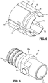
FIG. 5 is an enlarged view of the indicated area of detail shown inFIG. 2 ; -
FIG. 6 is an enlarged view of the indicated area of detail shown inFIG. 2 ; -
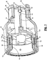
FIG. 7 is a cross-sectional view taken along section line 7-7 ofFIG. 3 ; -
FIG. 7A is a perspective view from the distal end of the knife carrier of the reload assembly shown inFIG. 2 ; -
FIG. 7B is a perspective view from the distal end of the shell housing of the reload assembly shown inFIG. 2 ; -
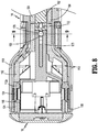
FIG. 8 is a cross-sectional view taken along section line 8-8 ofFIG. 1 ; -
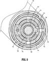
FIG. 9 is a cross-sectional view taken along section line 9-9 ofFIG. 8 ; -
FIG. 10 is a side cross-sectional view of the tool assembly of the surgical stapling device shown inFIG. 1 with the tool assembly in the clamped, pre-fired position; -
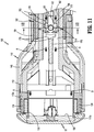
FIG. 11 is a side cross-sectional view of the tool assembly of the surgical stapling device shown inFIG. 1 with the tool assembly in the clamped, and fired position and the knife carrier in the advanced position; -
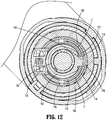
FIG. 12 is a cross-sectional view taken along section line 12-12 ofFIG. 11 ; -
FIG. 13 is a side cross-sectional view of the tool assembly of the surgical stapling device shown inFIG. 1 with the tool assembly in the clamped, and fired position and the knife carrier in the retracted position; -
FIG. 14 is a side perspective view of the reload assembly shown inFIG. 1 with the shell housing shown in phantom and including alternative aspects of the present disclosure; -
FIG. 15 is a side perspective assembled view of the bushing, EPROM chip holder, and stationary spring clip of the reload assembly shown inFIG. 14 ; -
FIG. 16 is a side perspective exploded view of the bushing, EPROM chip holder, and stationary spring clip of the reload assembly shown inFIG. 14 ; -
FIG. 17 is a side cross-sectional view of the reload assembly shown inFIG. 14 with the with the knife carrier in the retracted position; and -
FIG. 18 is a side cross-sectional view of the reload assembly shown inFIG. 14 with the knife carrier in the advanced position. - The disclosed reload assembly for a surgical stapling device will now be described in detail with reference to the drawings in which like reference numerals designate identical or corresponding elements in each of the several views. However, it is to be understood that the aspects of the reload assembly disclosed are merely exemplary of the disclosure and may be embodied in various forms. Well-known functions or constructions are not described in detail to avoid obscuring the disclosure in unnecessary detail. Therefore, specific structural and functional details disclosed herein are not to be interpreted as limiting, but merely as a basis for the claims and as a representative basis for teaching one skilled in the art to variously employ the disclosure in virtually any appropriately detailed structure. In addition, directional terms such as front, rear, upper, lower, top, bottom, distal, proximal, and similar terms are used to assist in understanding the description and are not intended to limit the disclosure.
- In this description, the term "proximal" is used generally to refer to that portion of the device that is closer to a clinician, while the term "distal" is used generally to refer to that portion of the device that is farther from the clinician. In addition, the term "clinician" is used generally to refer to medical personnel including doctors, nurses, and support personnel.
-
FIGS. 1 and2 illustrate acircular stapling device 10 including exemplary aspects of the disclosed reload assembly shown generally as reloadassembly 100. The staplingdevice 10 includes ahandle assembly 12, an elongate body oradaptor assembly 14, the reloadassembly 100, and ananvil assembly 18 that is supported for movement in relation to the reloadassembly 100 between spaced and clamped positions as is known in the art. The reloadassembly 100 includes aproximal portion 102 that is releasably coupled to adistal portion 14a of theelongate body 14. In certain aspects of the disclosure, thehandle assembly 12 includes astationary grip 22 that supportsactuation buttons 24 for controlling operation of various functions of the staplingdevice 10 including approximation of the reload andanvil assemblies assembly 100, and cutting or coring of tissue. - The stapling
device 10 is illustrated as an electrically powered stapling device including an electricallypowered handle assembly 12 that may support one or more batteries (not shown). Theelongate body 14 is in the form of an adaptor assembly that translates power from thehandle assembly 12 to the reload andanvil assemblies U.S. Patent Nos. 9,055,943 9,023,014 U.S. Publication Nos. 2018/0125495 , and2017/0340351 . Alternately, it is envisioned that the reload assembly could also be incorporated into a manually powered stapling device such as disclosed inU.S. Patent No. 7,303,106 (the '106 Patent) or a stapling device that is configured for use with a robotic system such as disclosed inU.S. Patent No. 9,962,159 -
FIGS. 2-4 illustrate the reloadassembly 100 which includes ashell housing 110, astaple actuator 112, astaple pushing member 112a, aknife carrier 114, anannular knife 116 supported on theknife carrier 114, astaple cartridge 118, and a plurality ofstaples 120 supported within thestaple cartridge 118. Thestaple cartridge 118 is annular and defines annular rows of staple pockets 124. Each of the staple pockets 124 supports one staple of the plurality ofstaples 120. Thestaple actuator 112 and thestaple pushing member 112a together define a longitudinal through bore 132 (FIG. 7 ). Thestaple actuator 112 has a distal portion that abuts a proximal portion of thestaple pushing member 112a such that distal movement of thestaple actuator 112 within theshell housing 110 causes distal movement of thestaple pushing member 112a within theshell housing 110. Thestaple pushing member 112a of the reloadassembly 100 has a plurality offingers 134. Each of the plurality offingers 134 is received within a respective one of the staple pockets 124 of thestaple cartridge 118 and is movable through the respectivestaple pocket 124 to eject one of thestaples 120 from thestaple pocket 124 when thestaple pushing member 112a is moved from a retracted position to an advanced position within theshell housing 110. - The
shell housing 110 includes anouter housing portion 140 and an inner housing portion 142 (FIG. 3 ) that are spaced from each other to define anannular cavity 144 between the outer andinner housing portions staple actuator 112 and thestaple pushing member 112a are movable within theannular cavity 144 of theshell housing 110 from retracted positions to advanced positions to eject thestaples 120 from thestaple cartridge 118. - The
annular knife 116 is supported about an outer surface of theknife carrier 114, has adistal cutting edge 117a, and defines acylindrical cavity 117. In aspects of the disclosure, theannular knife 116 includes inwardly extendingtangs 117b (FIG. 2 ) that are received withinpockets 114a defined in an outer surface of theknife carrier 114 to secure theannular knife 116 to theknife carrier 114. Theknife carrier 114 andannular knife 116 are positioned within the through bore 132 (FIG. 7 ) of thestaple actuator 112 and are movable from retracted positions to advanced positions to cut tissue positioned radially inward of thestaple cartridge 118. It is envisioned that theannular knife 116 can be secured to theknife carrier 114 using a variety of different fastening techniques. It is also envisioned that theannular knife 116 can be secured to an internal surface of theknife carrier 114 rather than to the outer surface of theknife carrier 114. - The
inner housing portion 142 of theshell housing 110 defines a through bore 150 (FIG. 3 ) that receives an anvil shaft (not shown) of theanvil assembly 18. For a more detailed description of anexemplary anvil assembly 18, see, e.g., the '106 Patent. The throughbore 150 has a proximal portion that receives abushing 152 best illustrated inFIG. 5 . Thebushing 152 includes a longitudinally fixed, rigidauxiliary detent 153 that extends radially outward from thebushing 152 and aflange 152a that extends at least partially about thebushing 152. Theflange 152a engages the proximal end of theinner housing portion 142 of theshell housing 110 to secure the bushing to theinner housing portion 142. Theauxiliary detent 153 is described in further detail below. Thebushing 152 defines a throughbore 150a that is coaxial with and forms an extension of the throughbore 150 of theinner housing portion 142. Thebushing 152 is formed of a high strength material, e.g., metal, to provide added strength to theinner housing portion 142 of theshell housing 110 and includes anannular flange 152a. In some aspects of the disclosure, thebushing 152 includes is distal end 154 that includes one or more retaining rings 154a. The retainingrings 154a are received within the throughbore 150 of theinner housing portion 142 of theshell housing 110 and are shaped to inhibit removal of thebushing 152. - The
shell housing 110 includes a proximal portion 158 (FIG. 2 ) that supports a coupling mechanism 160 (FIG. 2 ) that is operable to releasably couple the reloadassembly 100 to theadaptor assembly 14 of the stapling device 10 (FIG. 1 ). Thecoupling mechanism 160 allows for removal and replacement of the reloadassembly 100 on theelongate body 14 to facilitate reuse of the staplingdevice 10 and includes a retainingmember 162 and acoupling member 164. Thecoupling member 164 is received about theproximal portion 158 of theshell housing 110 and is configured to engage thedistal portion 14a (FIG. 1 ) of theadaptor assembly 14 to couple the reloadassembly 100 to theadaptor assembly 14. The retainingmember 162 retains thecoupling member 164 in a position about theproximal portion 158 of theshell housing 110. It is envisioned that other coupling mechanisms can be used to secure the reloadassembly 100 to theadaptor assembly 14. Alternately, the reloadassembly 100 can be non-removably secured to theadaptor assembly 14. - In certain aspects of the disclosure, the reload
assembly 100 includes an EPROM (erasable programmable read-only memory) chip holder 170 (FIG. 3 ) that is supported on theshell housing 110 and is configured to support an EPROM chip. As is known in the art, an EPROM chip communicates with theadaptor assembly 14 to provide information to theadaptor assembly 14 and thehandle assembly 12 regarding characteristics of the reloadassembly 10. In some aspects of the disclosure, theEPROM chip holder 170 includes acylindrical collar 170a (FIG. 2 ) that is received about a distal portion of thebushing 152 within theshell housing 110. Thecylindrical collar 170a can be clamped between the proximal end of theinner housing portion 142 of theshell housing 110 and theflange 152a of thebushing 152 to secure the EPROM chip holder within theshell housing 110. - The knife carrier 114 (
FIG. 2 ) includes spaced resilientlongitudinal body portions 173 that are spaced from each other and together define a central bore 172 (FIG. 7A ). Thecentral bore 172 of theknife carrier 114 is slidable about the inner housing portion 142 (FIG. 3 ) of theshell housing 110 such that theknife carrier 114 is movable about theinner housing portion 142 between a retracted position (FIG. 10 ) and an advanced position (FIG. 11 ). Each of thelongitudinal body portions 173 of theknife carrier 114 is formed of a resilient material and is spaced fromadjacent body portions 173 to defineslots 176 between theadjacent body portions 173. Theslots 176 receive guide portions 175 (FIG. 7B ) of theshell housing 110 to limit theknife carrier 114 to longitudinal movement within theshell housing 110. Theguide portions 175 extend between the inner andouter housing portions shell housing 110. At least one of thelongitudinal body portions 173 defines apocket 178 that communicates with one of theslots 176. In certain aspects of the disclosure, two of thelongitudinal body portions 173 definepockets 178 that are positioned in longitudinal alignment with each other on opposite sides of arespective slot 176 to define thepocket 178. Thepocket 178 receives theauxiliary detent 153 of thebushing 152 when theknife carrier 114 is in its retracted position. -
FIGS. 7A and 7B illustrate perspective views from the distal end of theknife carrier 114 and theshell housing 110. As illustrated, thelongitudinal body portions 173 of theknife carrier 114 include aninner surface 196 that defines thecentral bore 172 of theknife carrier 114 and supports one or moreprimary detents 196a. Theprimary detents 196a, of which four are shown, are supported about the periphery of theinner surface 196 of theknife carrier 114. In certain aspects of the disclosure, theprimary detents 196a are secured to theinner surface 196 of theknife carrier 114, although it is envisioned that the primary detents can be integrally formed with theknife carrier 114. - The outer surface of the
inner housing portion 142 includes one or more elongatedlongitudinal recesses 197. Therecesses 197, of which four are shown, each receive a respective one of theprimary detents 196a. Each of therecesses 197 include aproximal portion 197a and adistal portion 197b that are separated by anabutment surface 198. When theknife carrier 114 is in its retracted position, theprimary detents 196a are received in theproximal portion 197a of therecesses 197 formed in theinner housing portion 142 of theknife carrier 110 at a positon adjacent theabutment surface 198. When theknife carrier 114 is advanced from its retracted position towards its advanced position, theprimary detents 196a are forced to pass over theabutment surface 198 and pass into thedistal portion 197b of therecesses 197. As thedetents 196a pass over theabutment surface 198, thedetents 196a are in an interference fit with theabutment surface 198. -
FIG. 6 illustrates a proximal portion of theknife carrier 114 which defines an outwardly facing annular recess orchannel 180 that extends about each of thelongitudinal body portions 173. Thechannel 180 is defined on its proximal end by atapered abutment 181 and is configured to releasably receive an inwardly extendingengagement portion 182a (FIG. 10 ) of a knife band ordriver 182 to facilitate movement of theknife driver 114 between its retracted and advanced positions. Thelongitudinal body portions 173 of theknife carrier 114 are formed of a resilient material to allow thelongitudinal body portions 173 to flex inwardly and outwardly into and out of engagement with theknife driver 182. This structure facilitates removal and replacement of the reloadassembly 100 in relation to theelongate body 114 of the staplingdevice 10. -
FIGS. 7-10 illustrate the reload assembly in a clamped, pre-fired position. In this position, the staple actuator 112 (FIG. 8 ), thestaple pushing member 112a, theknife carrier 114, and theannular knife 116 are in their retracted positions. When theknife carrier 114 is in its retracted position, theannular knife 116 is recessed within thestaple cartridge 118 and theauxiliary detent 153 of thebushing 152 is received within thepocket 178 of thelongitudinal body portions 172 of theknife carrier 114. In this position, theauxiliary detent 153 is aligned with a respective one of theslots 176 defined betweenadjacent body portions 173 of theknife carrier 114. In addition, as described above, when theknife carrier 114 is in its retracted position, theprimary detents 196a are received in theproximal portion 197a of therecesses 197 in theinner housing portion 142 of theshell housing 110 at a positon adjacent theabutment surface 198. - When the
staple actuator 112 is in its retracted position, thestaple pushing member 112a is also in its retracted position with thefingers 134 of thestaple pushing member 112a aligned with and positioned proximally of thestaples 120 supported within the staple pockets 124. Although not described in detail herein, theadapter assembly 14 includes astaple driver 184 and theknife driver 182. As described above, theknife driver 182 is coupled to theknife carrier 114 and is longitudinally movable to move theknife carrier 114 between its advanced and retracted positions. Similarly, thestaple driver 184 is coupled to thestaple actuator 112 and is longitudinally movable to move thestaple actuator 112 between its retracted and advanced positions. -
FIGS. 11-12 illustrate the reloadassembly 100 in a clamped position with theknife carrier 114 and thestaple actuator 112 moving towards their fully advanced fired positions. When the stapling device 10 (FIG. 1 ) is actuated by depressingactuation buttons 24 on the handle assembly 12 (FIG. 1 ), theknife driver 182 and thestaple driver 184 are advanced within theelongate body 14 to advance theknife carrier 114 and thestaple actuator 112 within theshell housing 110. As thestaple driver 184 and theknife driver 182 are advanced in the direction indicated by arrows "A" inFIG. 11 , thestaple actuator 112 and theknife carrier 114, which are coupled to thestaple driver 184 and theknife driver 182, respectively, are advanced from their retracted positions (FIG. 10 ) towards their advanced positions (FIG. 11 ). It is envisioned that thestaple driver 184 is advanced before or simultaneously with theknife driver 182 to ensure that tissue is sutured or stapled prior to being cut. As described above, thestaple actuator 112 is in abutting relation to thestaple pushing member 112a. As such, when thestaple actuator 112 is advanced, thestaple pushing member 112a is advanced to move thefingers 134 of thestaple pushing member 112a through the staple pockets 124 in thecartridge 118 to eject thestaples 120 from thecartridge 118. When theknife driver 182 is advanced, theknife carrier 114 is advanced to advance theannular knife 116 in the direction indicated by arrows "B" inFIG. 11 into engagement with a cut ring assembly 190 (FIG. 11 ) of theanvil assembly 18 to cut tissue clamped between theanvil assembly 18 and thecartridge 118. - When the
knife carrier 114 is advanced from its retracted position towards its advanced position, theprimary detents 196a are forced to pass over theabutment surface 198 and pass into thedistal portion 197b of therecesses 197. As thedetents 196a pass over theabutment surface 198, thedetents 196a are in an interference fit with theabutment surface 198. The interaction between theprimary detents 196a and therecesses 197 increases the knife carrier retention force within the reloadassembly 100 as described in further detail below. - The
bushing 152 and theauxiliary detent 153 are fixedly supported within theshell housing 110. When theknife carrier 114 is advanced within theshell housing 110 from its retracted position towards its advanced position, thelongitudinal body portions 173 move in relation to theauxiliary detent 153 to removeauxiliary detent 153 from a position within thepocket 178 of thelongitudinal body portions 173 to a position within one of theslots 176. The width (or diameter) of theauxiliary detent 153 is greater than the width of theslots 176. As such, when theauxiliary detent 153 is positioned within one of theslots 176 defined by thelongitudinal body portions 173 of theknife carrier 114, as theknife carrier 114 moves within theshell housing 110 from its retracted position to its advanced position, the adjacentlongitudinal body portions 173 that define theslot 176 are biased outwardly in the direction indicated by arrows "C" inFIG. 11 . As shown, when thelongitudinal body portions 173 are biased outwardly, thetapered abutment 181 of theknife driver 114 and theengagement portion 182a of theknife driver 182 are urged into tight engagement to prevent separation of theknife driver 182 and theknife carrier 114. -
FIG. 13 illustrates the reloadassembly 100 in a fired and clamped position with theknife carrier 114 and thestaple actuator 112 returned in the direction indicated by arrows "D" to their retracted positions. When theknife carrier 114 is returned to its retracted position after firing of the stapling device 10 (FIG. 1 ), theauxiliary detent 153 moves through thelongitudinal slot 176 and returns a position within thepocket 178. Engagement between theauxiliary detent 153 and thelongitudinal body portions 173 of theknife carrier 114 maintain engagement between theknife driver 182 and theknife carrier 114 until the auxiliary detent passes back into thepocket 178. When theauxiliary detent 153 is received within thepocket 178, thelongitudinal body portions 173 move inwardly in the direction of arrows "E" to reduce the engagement force between thetapered abutments 181 of theknife carrier 114 and theengagement portion 182a of theknife driver 182. As theknife carrier 114 is retracted, theannular knife 116 is retracted to a position recessed within thestaple cartridge 118 to shield thecutting edge 117a of theannular knife 116 from the clinician. Theauxiliary detent 153 obstructs further advancement of theknife carrier 114. More particularly, theauxiliary detent 153 is positioned to engageinner walls 192 that define thepocket 178 to obstruct readvancement off theknife carrier 114 and, thus readvancement of theannular knife 116 from its shielded position within thestaple cartridge 118. - When the
knife carrier 114 is returned to its retracted position, theprimary detents 196a move proximally from thedistal portion 197b of therecesses 197, across theabutment surface 198, and back into theproximal portion 197a of therecesses 197. When thedetents 196a are received in theproximal portion 197a of therecesses 197, engagement between thedetents 196a and theabutment surface 198 increases the retention force on theknife carrier 114 to minimize any likelihood of readvancement of theknife carrier 114. -
FIGS. 14-18 illustrate a reload assembly shown generally as reloadassembly 200 including additional aspects of the disclosure. The reloadassembly 200 is substantially similar to reloadassembly 100 with the exception that the auxiliary detent 153 (FIG. 2 ) of thebushing 252 has been replaced by a longitudinally fixed, resilient auxiliary detent, e.g., aspring clip 253. In certain aspects of the disclosure, the resilientauxiliary detent 253 is secured to asupport ring 254 that is received about the about thebushing 252. In certain aspects of the disclosure, thesupport ring 254 is secured to thebushing 252 and compressed between thecylindrical collar 270a of theEPROM holder 270 and the flange 252a (FIG. 16 ) of thebushing 252. Theflange 252a may include a flat 252b that supports thespring clip 253. It is envisioned that the resilientauxiliary detent 253 can be secured to thebushing 252 in a variety different manners using a variety of different techniques. - When the
knife carrier 214 is in a retracted position (FIG. 14 ), the resilientauxiliary detent 253 is received within thepocket 278 of theknife carrier 214. In certain aspects of the disclosure, the resilientauxiliary detent 253 includes a tapered, distally facingengagement surface 294 that is aligned with theinner walls 292 that define thepocket 278 in the longitudinally extending body portions 273 of theknife carrier 214. When theknife carrier 214 is moved from its retracted position (FIG. 17 ) towards its advanced position, the resilientauxiliary detent 253 is deformed inwardly by theinner walls 292 of theknife carrier 214 as theknife carrier 214 drives over the resilientauxiliary detent 253. In its deformed state (FIG. 18 ), the resilientauxiliary detent 253 applies an outwardly directed force onto the longitudinally extending body portion 273 of theknife carrier 214 to urge theknife carrier 214 into more secure engagement with the knife driver 182 (FIG. 11 ). After the reload 200 is fired and theknife carrier 214 is returned to its retracted position (FIG. 17 ), the resilientauxiliary detent 253 returns to a position located within thepocket 278 to obstruct further advancement of theknife carrier 214. - The resilient
auxiliary detent 253 of the reloadassembly 200 and the fixedauxiliary detent 153 of the reloadassembly 100 in combination with theprimary detents 196a on theknife carrier shell housing - Persons skilled in the art will understand that the devices and methods specifically described herein and illustrated in the accompanying drawings are non-limiting exemplary embodiments. It is envisioned that the elements and features illustrated or described in connection with one exemplary embodiment may be combined with the elements and features of another without departing from the scope of the disclosure. As well, one skilled in the art will appreciate further features and advantages of the disclosure based on the above-described embodiments. Accordingly, the disclosure is not to be limited by what has been particularly shown and described, except as indicated by the appended claims.
- The invention may be described by reference to the following numbered paragraphs:
- 1. A surgical stapling device comprising: an adaptor assembly having a proximal end portion and a distal end portion; and a reload assembly supported on the distal end portion of the adaptor assembly, the reload assembly including: a shell housing including an outer housing portion and an inner housing portion, the inner and outer housing portions defining an annular cavity; an auxiliary detent supported within the shell housing; a staple cartridge secured to the shell housing and supporting a plurality of staples; a staple pusher defining a through bore, the staple pusher supported within the annular cavity and movable from a retracted position to an advanced position to eject the plurality of staples from the staple cartridge; a knife carrier supported within the through bore of the staple pusher and defining a central bore that receives the inner housing portion of the shell housing, the knife carrier movable about the inner housing portion between a retracted position and an advanced position, the knife carrier defining a pocket that receives the auxiliary detent when the knife carrier is in the retracted position to obstruct movement of the knife carrier from the retracted position towards the advanced position; and an annular knife supported on the knife carrier.
- 2. The surgical stapling device of paragraph 1, further including a handle assembly, the proximal end portion of the adaptor assembly being supported on the handle assembly.
- 3. The surgical stapling device of paragraph 1, wherein the auxiliary detent is longitudinally fixed to the shell housing.
- 4. The surgical stapling device of paragraph 3, wherein the auxiliary detent is resilient.
- 5. The surgical stapling device of paragraph 3, wherein the auxiliary detent is rigid.
- 6. The surgical stapling device of paragraph 1, wherein the knife carrier includes an inner surface that defines the central bore of the knife carrier, the inner surface of the knife carrier supporting at least one primary detent, the inner housing portion of the shell housing including an outer surface that defines at least one longitudinal recess that receives the at least one primary detent, the at least one primary detent having a proximal portion, a distal portion, and an abutment surface that separates the proximal portion of the at least one recess from the distal portion of the at least one recess, wherein the at least one primary detent moves into an interference fit with the abutment surface as the knife carrier is moved from its retracted position towards it advanced position.
- 7. The surgical stapling device of paragraph 4, wherein the auxiliary detent is in the form of a spring clip.
- 8. The surgical stapling device of paragraph 1, wherein the knife carrier includes a plurality of resilient longitudinal body portions that define the central bore, each of the longitudinal body portions being spaced from adjacent longitudinal body portions to define longitudinal slots.
- 9. The surgical stapling device of paragraph 1, wherein the pocket is defined in adjacent longitudinal body portions of the knife carrier and communicates with a respective one of the longitudinal slots such that the auxiliary detent is aligned with the respective one of the longitudinal slots, the auxiliary detent being movable into the respective one of the longitudinal slots as the knife carrier moves from its retracted position towards its advanced position.
- 10. The surgical stapling device of
paragraph 9, wherein the adaptor assembly includes a knife driver that is adapted to be releasably coupled to the knife carrier. - 11. The surgical stapling device of
paragraph 10, wherein the width of the auxiliary detent is greater than the width of the respective one of the longitudinal slots such that movement of the auxiliary detent through the at least one of the longitudinal slots causes deformation of the adjacent longitudinal body portions to urge the knife driver and the knife carrier into more secure engagement. - 12. The surgical stapling device of paragraph 1, further including a bushing secured to the inner housing portion of the shell housing, wherein the auxiliary detent is supported on the bushing.
- 13. A reload assembly comprising: a shell housing including an outer housing portion and an inner housing portion, the inner and outer housing portions defining an annular cavity; an auxiliary detent supported within the shell housing; a staple cartridge secured to the shell housing and supporting a plurality of staples; a staple pusher defining a through bore, the staple pusher supported within the annular cavity and movable from a retracted position to an advanced position to eject the plurality of staples from the staple cartridge; a knife carrier supported within the through bore of the staple pusher and defining a central bore that receives the inner housing portion of the shell housing, the knife carrier movable about the inner housing portion between a retracted position and an advanced position, the knife carrier defining a pocket that receives the auxiliary detent when the knife carrier is in the retracted position to obstruct movement of the knife carrier from the retracted position towards the advanced position; and a knife supported on the knife carrier.
- 14. The reload assembly of paragraph 13, wherein the knife carrier includes an inner surface that defines the central bore of the knife carrier, the inner surface of the knife carrier supporting at least one primary detent, the inner housing portion of the shell housing including an outer surface that defines at least one longitudinal recess that receives the at least one primary detent, the at least one primary detent having a proximal portion, a distal portion, and an abutment surface that separates the proximal portion of the at least one recess from the distal portion of the at least one recess, wherein the at least one primary detent moves into an interference fit with the abutment surface as the knife carrier is moved from its retracted position towards it advanced position.
- 15. The reload assembly of
paragraph 14, wherein the auxiliary detent is longitudinally fixed to the shell housing. - 16. The reload assembly of paragraph 15, wherein the auxiliary detent is resilient and includes a spring clip.
- 17. The reload assembly of paragraph 15, wherein the auxiliary detent is rigid.
- 18. The reload assembly of paragraph 13, wherein the knife carrier includes a plurality of resilient longitudinal body portions that define the central bore, each of the longitudinal body portions being spaced from adjacent longitudinal body portions to define longitudinal slots.
- 19. The reload assembly of paragraph 13, wherein the pocket is defined in adjacent longitudinal body portions of the knife carrier and communicates with a respective one of the longitudinal slots such that the auxiliary detent is aligned with the respective one of the longitudinal slots, the auxiliary detent being movable into the respective one of the longitudinal slots as the knife carrier moves from its retracted position towards its advanced position.
- 20. The reload assembly of paragraph 19, wherein the width of the auxiliary detent is greater than the width of the respective one of the longitudinal slots such that movement of the auxiliary detent through the respective one of the longitudinal slots causes outward deformation of the adjacent longitudinal body portions.
- 21. The reload assembly of paragraph 13, further including a bushing secured to the inner housing portion of the shell housing, wherein the auxiliary detent is supported on the bushing.
Claims (15)
- A surgical stapling device comprising:an adaptor assembly having a proximal end portion and a distal end portion; anda reload assembly supported on the distal end portion of the adaptor assembly, the reload assembly including:a shell housing including an outer housing portion and an inner housing portion, the inner and outer housing portions defining an annular cavity;an auxiliary detent supported within the shell housing;a staple cartridge secured to the shell housing and supporting a plurality of staples;a staple pusher defining a through bore, the staple pusher supported within the annular cavity and movable from a retracted position to an advanced position to eject the plurality of staples from the staple cartridge;a knife carrier supported within the through bore of the staple pusher and defining a central bore that receives the inner housing portion of the shell housing, the knife carrier movable about the inner housing portion between a retracted position and an advanced position, the knife carrier defining a pocket that receives the auxiliary detent when the knife carrier is in the retracted position to obstruct movement of the knife carrier from the retracted position towards the advanced position; andan annular knife supported on the knife carrier.
- The surgical stapling device of claim 1, further including a handle assembly, the proximal end portion of the adaptor assembly being supported on the handle assembly.
- The surgical stapling device of claim 1 or claim 2, wherein the auxiliary detent is longitudinally fixed to the shell housing.
- The surgical stapling device of claim 3, wherein the auxiliary detent is resilient; or wherein the auxiliary detent is rigid.
- The surgical stapling device of any preceding claim, wherein the knife carrier includes an inner surface that defines the central bore of the knife carrier, the inner surface of the knife carrier supporting at least one primary detent, the inner housing portion of the shell housing including an outer surface that defines at least one longitudinal recess that receives the at least one primary detent, the at least one primary detent having a proximal portion, a distal portion, and an abutment surface that separates the proximal portion of the at least one recess from the distal portion of the at least one recess, wherein the at least one primary detent moves into an interference fit with the abutment surface as the knife carrier is moved from its retracted position towards it advanced position.
- The surgical stapling device of claim 3, wherein the auxiliary detent is in the form of a spring clip.
- The surgical stapling device of any preceding claim, wherein the knife carrier includes a plurality of resilient longitudinal body portions that define the central bore, each of the longitudinal body portions being spaced from adjacent longitudinal body portions to define longitudinal slots; and/or wherein the pocket is defined in adjacent longitudinal body portions of the knife carrier and communicates with a respective one of the longitudinal slots such that the auxiliary detent is aligned with the respective one of the longitudinal slots, the auxiliary detent being movable into the respective one of the longitudinal slots as the knife carrier moves from its retracted position towards its advanced position.
- The surgical stapling device of claim 7, wherein the adaptor assembly includes a knife driver that is adapted to be releasably coupled to the knife carrier; preferably wherein the width of the auxiliary detent is greater than the width of the respective one of the longitudinal slots such that movement of the auxiliary detent through the at least one of the longitudinal slots causes deformation of the adjacent longitudinal body portions to urge the knife driver and the knife carrier into more secure engagement.
- The surgical stapling device of any preceding claim, further including a bushing secured to the inner housing portion of the shell housing, wherein the auxiliary detent is supported on the bushing.
- A reload assembly comprising:a shell housing including an outer housing portion and an inner housing portion, the inner and outer housing portions defining an annular cavity;an auxiliary detent supported within the shell housing;a staple cartridge secured to the shell housing and supporting a plurality of staples;a staple pusher defining a through bore, the staple pusher supported within the annular cavity and movable from a retracted position to an advanced position to eject the plurality of staples from the staple cartridge;a knife carrier supported within the through bore of the staple pusher and defining a central bore that receives the inner housing portion of the shell housing, the knife carrier movable about the inner housing portion between a retracted position and an advanced position, the knife carrier defining a pocket that receives the auxiliary detent when the knife carrier is in the retracted position to obstruct movement of the knife carrier from the retracted position towards the advanced position; anda knife supported on the knife carrier.
- The reload assembly of claim 10, wherein the knife carrier includes an inner surface that defines the central bore of the knife carrier, the inner surface of the knife carrier supporting at least one primary detent, the inner housing portion of the shell housing including an outer surface that defines at least one longitudinal recess that receives the at least one primary detent, the at least one primary detent having a proximal portion, a distal portion, and an abutment surface that separates the proximal portion of the at least one recess from the distal portion of the at least one recess, wherein the at least one primary detent moves into an interference fit with the abutment surface as the knife carrier is moved from its retracted position towards it advanced position; preferably wherein the auxiliary detent is longitudinally fixed to the shell housing.
- The reload assembly of claim 11, wherein the auxiliary detent is resilient and includes a spring clip; or wherein the auxiliary detent is rigid.
- The reload assembly of any of claims 10 to 12, wherein the knife carrier includes a plurality of resilient longitudinal body portions that define the central bore, each of the longitudinal body portions being spaced from adjacent longitudinal body portions to define longitudinal slots.
- The reload assembly of any of claims 10 to 13, wherein the pocket is defined in adjacent longitudinal body portions of the knife carrier and communicates with a respective one of the longitudinal slots such that the auxiliary detent is aligned with the respective one of the longitudinal slots, the auxiliary detent being movable into the respective one of the longitudinal slots as the knife carrier moves from its retracted position towards its advanced position; preferably wherein the width of the auxiliary detent is greater than the width of the respective one of the longitudinal slots such that movement of the auxiliary detent through the respective one of the longitudinal slots causes outward deformation of the adjacent longitudinal body portions.
- The reload assembly of any of claims 10 to 14, further including a bushing secured to the inner housing portion of the shell housing, wherein the auxiliary detent is supported on the bushing.
Applications Claiming Priority (2)
| Application Number | Priority Date | Filing Date | Title |
|---|---|---|---|
| US201962948400P | 2019-12-16 | 2019-12-16 | |
| US17/088,160 US11553918B2 (en) | 2019-12-16 | 2020-11-03 | Reload assembly with knife carrier lockout |
Publications (2)
| Publication Number | Publication Date |
|---|---|
| EP3838185A1 true EP3838185A1 (en) | 2021-06-23 |
| EP3838185B1 EP3838185B1 (en) | 2024-01-24 |
Family
ID=73838941
Family Applications (1)
| Application Number | Title | Priority Date | Filing Date |
|---|---|---|---|
| EP20214062.0A Active EP3838185B1 (en) | 2019-12-16 | 2020-12-15 | Reload assembly with knife carrier lockout |
Country Status (3)
| Country | Link |
|---|---|
| US (1) | US11553918B2 (en) |
| EP (1) | EP3838185B1 (en) |
| CN (1) | CN112971898B (en) |
Families Citing this family (1)
| Publication number | Priority date | Publication date | Assignee | Title |
|---|---|---|---|---|
| CN119365125A (en) * | 2022-06-29 | 2025-01-24 | 柯惠有限合伙公司 | Real-time suture tissue perfusion assessment |
Citations (8)
| Publication number | Priority date | Publication date | Assignee | Title |
|---|---|---|---|---|
| US7303106B2 (en) | 2002-10-04 | 2007-12-04 | Tyco Healthcare Group Lp | Surgical stapling device with visual indicator |
| US9023014B2 (en) | 2007-09-21 | 2015-05-05 | Covidien Lp | Quick connect assembly for use between surgical handle assembly and surgical accessories |
| US9055943B2 (en) | 2007-09-21 | 2015-06-16 | Covidien Lp | Hand held surgical handle assembly, surgical adapters for use between surgical handle assembly and surgical end effectors, and methods of use |
| EP2997908A1 (en) * | 2014-07-09 | 2016-03-23 | Covidien LP | Methods and devices for performing a surgical anastomosis |
| US20170340351A1 (en) | 2016-05-31 | 2017-11-30 | Covidien Lp | Flexible trocar assembly for surgical circular stapling devices |
| US9962159B2 (en) | 2002-04-25 | 2018-05-08 | Covidien Lp | Surgical instruments including MEMS devices |
| US20180125495A1 (en) | 2016-11-04 | 2018-05-10 | Covidien Lp | Stapling device with self-releasing knife carrier pusher |
| EP3378411A1 (en) * | 2017-03-23 | 2018-09-26 | Covidien LP | Surgical stapling device with releasable knife carrier |
Family Cites Families (351)
| Publication number | Priority date | Publication date | Assignee | Title |
|---|---|---|---|---|
| CA908529A (en) | 1972-08-29 | V. Astafiev Georgy | Surgical instrument for suturing hollow organs in infants | |
| DE1057729B (en) | 1954-03-29 | 1959-05-21 | Lameris Instr N V | Surgical device for connecting two parts of the intestine |
| GB787043A (en) | 1954-09-15 | 1957-11-27 | Sylvania Electric Prod | Method for production of silicon |
| CA736256A (en) | 1962-08-27 | 1966-06-14 | S. Kasoolin Viacheslav | Instrument for suturing esophagus to intestine or stomach |
| FR1461464A (en) | 1965-08-20 | 1966-02-25 | Niiex Khirurgicheskoi Apparatu | Surgical device for suturing organs |
| CH470170A (en) | 1968-02-02 | 1969-03-31 | Vnii Khirurgicheskoi Apparatur | Device for applying round anastomoses |
| US3638652A (en) | 1970-06-01 | 1972-02-01 | James L Kelley | Surgical instrument for intraluminal anastomosis |
| US3771526A (en) | 1972-02-07 | 1973-11-13 | P Rudie | Anastomosis clamp |
| US4603693A (en) | 1977-05-26 | 1986-08-05 | United States Surgical Corporation | Instrument for circular surgical stapling of hollow body organs and disposable cartridge therefor |
| US4573468A (en) | 1977-05-26 | 1986-03-04 | United States Surgical Corporation | Hollow body organ stapling instrument and disposable cartridge employing relief vents |
| US4304236A (en) | 1977-05-26 | 1981-12-08 | United States Surgical Corporation | Stapling instrument having an anvil-carrying part of particular geometric shape |
| NL7711347A (en) | 1977-10-17 | 1979-04-19 | Carl Robert Erik Daantje | Stapling instrument for joining intestine ends - has head coupling rod in two parts screwing together with hand grip |
| US4207898A (en) | 1978-03-27 | 1980-06-17 | Senco Products, Inc. | Intralumenal anastomosis surgical stapling instrument |
| US4198982A (en) | 1978-03-31 | 1980-04-22 | Memorial Hospital For Cancer And Allied Diseases | Surgical stapling instrument and method |
| DE2947107A1 (en) | 1978-12-07 | 1980-06-26 | United States Surgical Corp | ACCURATELY ALIGNED CARTRIDGE AND INSTRUMENT FOR CLAMPING ANASTOMOSES |
| SU1088712A1 (en) | 1979-11-14 | 1984-04-30 | Всесоюзный научно-исследовательский и испытательный институт медицинской техники | Apparatus for circular suture of blood vessels |
| AU534210B2 (en) | 1980-02-05 | 1984-01-12 | United States Surgical Corporation | Surgical staples |
| US4319576A (en) | 1980-02-26 | 1982-03-16 | Senco Products, Inc. | Intralumenal anastomosis surgical stapling instrument |
| US4289133A (en) | 1980-02-28 | 1981-09-15 | Senco Products, Inc. | Cut-through backup washer for the scalpel of an intraluminal surgical stapling instrument |
| US4606343A (en) | 1980-08-18 | 1986-08-19 | United States Surgical Corporation | Self-powered surgical fastening instrument |
| US4351466A (en) | 1980-10-16 | 1982-09-28 | United States Surgical Corporation | Disposable instrument for surgical fastening |
| US4379457A (en) | 1981-02-17 | 1983-04-12 | United States Surgical Corporation | Indicator for surgical stapler |
| US4476863A (en) | 1981-03-09 | 1984-10-16 | Kanshin Nikolai N | Surgical instrument for establishing circular coloanastomoses |
| US4632290A (en) | 1981-08-17 | 1986-12-30 | United States Surgical Corporation | Surgical stapler apparatus |
| US4576167A (en) | 1981-09-03 | 1986-03-18 | United States Surgical Corporation | Surgical stapler apparatus with curved shaft |
| SU1114405A1 (en) | 1982-02-23 | 1984-09-23 | Всесоюзный научно-исследовательский и испытательный институт медицинской техники | Surgical suturing apparatus for placing compression anastomoses on the organs of digestive tract |
| US4473077A (en) | 1982-05-28 | 1984-09-25 | United States Surgical Corporation | Surgical stapler apparatus with flexible shaft |
| US4485817A (en) | 1982-05-28 | 1984-12-04 | United States Surgical Corporation | Surgical stapler apparatus with flexible shaft |
| US4488523A (en) | 1982-09-24 | 1984-12-18 | United States Surgical Corporation | Flexible, hydraulically actuated device for applying surgical fasteners |
| DE3301713A1 (en) | 1983-01-20 | 1984-07-26 | Horst Dr. 3004 Isernhagen Ziegler | Surgical clip suture apparatus for producing circular joins |
| US4592354A (en) | 1983-10-11 | 1986-06-03 | Senmed, Inc. | Tissue retention spool for intraluminal anastomotic surgical stapling instrument and methods |
| US4505414A (en) | 1983-10-12 | 1985-03-19 | Filipi Charles J | Expandable anvil surgical stapler |
| US4550870A (en) | 1983-10-13 | 1985-11-05 | Alchemia Ltd. Partnership | Stapling device |
| IT1173284B (en) | 1984-02-16 | 1987-06-18 | Riccardo Rosati | CIRCULAR MECHANICAL STAPLING MACHINE |
| US4667673A (en) | 1984-03-12 | 1987-05-26 | American Cyanamid Company | Anastomotic device applicator and method |
| US4671445A (en) | 1984-08-09 | 1987-06-09 | Baxter Travenol Laboratories, Inc. | Flexible surgical stapler assembly |
| US4754909A (en) | 1984-08-09 | 1988-07-05 | Barker John M | Flexible stapler |
| US4703887A (en) | 1985-01-28 | 1987-11-03 | Ethicon, Inc. | Collapsible purse string aid for use with intraluminal stapling device |
| AU582625B2 (en) | 1985-01-28 | 1989-04-06 | Ethicon Inc. | Tissue gripper for use with intraluminal stapling device |
| US4665917A (en) | 1985-01-28 | 1987-05-19 | Ethicon, Inc. | Tissue gripper for use with intraluminal stapling device |
| JPS635697Y2 (en) | 1985-04-04 | 1988-02-17 | ||
| JPS62140776A (en) | 1985-12-16 | 1987-06-24 | 海老原 代師行 | Stapler |
| US4903697A (en) | 1986-03-27 | 1990-02-27 | Semion Resnick | Cartridge assembly for a surgical stapling instrument |
| US4700703A (en) | 1986-03-27 | 1987-10-20 | Semion Resnick | Cartridge assembly for a surgical stapling instrument |
| AU7286587A (en) | 1986-04-21 | 1987-11-24 | Globe Control Finanzaktiengesellschaft | Anastomosis process and device |
| US4917114A (en) | 1986-10-17 | 1990-04-17 | United States Surgical Corporation | Surgical fastener and surgical stapling apparatus |
| US4752024A (en) | 1986-10-17 | 1988-06-21 | Green David T | Surgical fastener and surgical stapling apparatus |
| US4776506A (en) | 1986-11-13 | 1988-10-11 | United States Surgical Corporation | Surgical stapler apparatus |
| US4873977A (en) | 1987-02-11 | 1989-10-17 | Odis L. Avant | Stapling method and apparatus for vesicle-urethral re-anastomosis following retropubic prostatectomy and other tubular anastomosis |
| US5119983A (en) | 1987-05-26 | 1992-06-09 | United States Surgical Corporation | Surgical stapler apparatus |
| US5158222A (en) | 1987-05-26 | 1992-10-27 | United States Surgical Corp. | Surgical stapler apparatus |
| US5285944A (en) | 1987-05-26 | 1994-02-15 | United States Surgical Corporation | Surgical stapler apparatus |
| SU1616624A1 (en) | 1987-07-14 | 1990-12-30 | Предприятие П/Я А-3697 | Surgical suturing apparatus |
| SU1509052A1 (en) | 1988-01-18 | 1989-09-23 | С. А. Попов | Surgical suturing apparatus |
| US4907591A (en) | 1988-03-29 | 1990-03-13 | Pfizer Hospital Products Group, Inc. | Surgical instrument for establishing compression anastomosis |
| US5193731A (en) | 1988-07-01 | 1993-03-16 | United States Surgical Corporation | Anastomosis surgical stapling instrument |
| US5005749A (en) | 1988-07-01 | 1991-04-09 | United States Surgical Corp. | Anastomosis surgical stapling instrument |
| ES2011110A6 (en) | 1988-09-02 | 1989-12-16 | Lopez Hervas Pedro | Hydraulic device with flexible body for surgical anastomosts |
| US5197648A (en) | 1988-11-29 | 1993-03-30 | Gingold Bruce S | Surgical stapling apparatus |
| WO1990006085A1 (en) | 1988-11-29 | 1990-06-14 | Gingold Bruce S | Surgical stapling apparatus |
| US4893662A (en) | 1988-12-06 | 1990-01-16 | Vito Gervasi | Cutting tool |
| CH677728A5 (en) | 1989-10-17 | 1991-06-28 | Bieffe Medital Sa | |
| US5366462A (en) | 1990-08-28 | 1994-11-22 | Robert L. Kaster | Method of side-to-end vascular anastomotic stapling |
| US5047039A (en) | 1990-09-14 | 1991-09-10 | Odis Lynn Avant | Method and apparatus for effecting dorsal vein ligation and tubular anastomosis and laparoscopic prostatectomy |
| US5253793A (en) | 1990-09-17 | 1993-10-19 | United States Surgical Corporation | Apparatus for applying two-part surgical fasteners |
| US5104025A (en) | 1990-09-28 | 1992-04-14 | Ethicon, Inc. | Intraluminal anastomotic surgical stapler with detached anvil |
| US5042707A (en) | 1990-10-16 | 1991-08-27 | Taheri Syde A | Intravascular stapler, and method of operating same |
| CA2055943C (en) | 1990-12-06 | 2003-09-23 | Daniel P. Rodak | Surgical fastening apparatus with locking mechanism |
| US5122156A (en) | 1990-12-14 | 1992-06-16 | United States Surgical Corporation | Apparatus for securement and attachment of body organs |
| US5222963A (en) | 1991-01-17 | 1993-06-29 | Ethicon, Inc. | Pull-through circular anastomosic intraluminal stapler with absorbable fastener means |
| DE69208991T2 (en) | 1991-03-29 | 1996-07-25 | Perouse Implant Lab | Surgical stapler |
| US5221036A (en) | 1991-06-11 | 1993-06-22 | Haruo Takase | Surgical stapler |
| US5333773A (en) | 1991-08-23 | 1994-08-02 | Ethicon, Inc. | Sealing means for endoscopic surgical anastomosis stapling instrument |
| GR920100358A (en) | 1991-08-23 | 1993-06-07 | Ethicon Inc | Surgical anastomosis stapling instrument. |
| US5350104A (en) | 1991-08-23 | 1994-09-27 | Ethicon, Inc. | Sealing means for endoscopic surgical anastomosis stapling instrument |
| US5474223A (en) | 1991-10-18 | 1995-12-12 | United States Surgical Corporation | Surgical fastener applying apparatus |
| US5443198A (en) | 1991-10-18 | 1995-08-22 | United States Surgical Corporation | Surgical fastener applying apparatus |
| US5197649A (en) | 1991-10-29 | 1993-03-30 | The Trustees Of Columbia University In The City Of New York | Gastrointestinal endoscoptic stapler |
| US5433721A (en) | 1992-01-17 | 1995-07-18 | Ethicon, Inc. | Endoscopic instrument having a torsionally stiff drive shaft for applying fasteners to tissue |
| US5188638A (en) | 1992-02-06 | 1993-02-23 | Tzakis Andreas G | Apparatus and method for preforming anastomosis fastener securement of hollow organs |
| US5271543A (en) | 1992-02-07 | 1993-12-21 | Ethicon, Inc. | Surgical anastomosis stapling instrument with flexible support shaft and anvil adjusting mechanism |
| US5348259A (en) | 1992-02-10 | 1994-09-20 | Massachusetts Institute Of Technology | Flexible, articulable column |
| US5282810A (en) | 1992-04-08 | 1994-02-01 | American Cyanamid Company | Surgical anastomosis device |
| US5425738A (en) | 1992-04-08 | 1995-06-20 | American Cyanamid Company | Endoscopic anastomosis ring insertion device and method of use thereof |
| US5355897A (en) | 1992-04-16 | 1994-10-18 | Ethicon, Inc. | Method of performing a pyloroplasty/pylorectomy using a stapler having a shield |
| US5314435A (en) | 1992-05-19 | 1994-05-24 | United States Surgical Corporation | Anvil delivery system |
| US5344059A (en) | 1992-05-19 | 1994-09-06 | United States Surgical Corporation | Surgical apparatus and anvil delivery system therefor |
| JPH0647050A (en) | 1992-06-04 | 1994-02-22 | Olympus Optical Co Ltd | Tissue suture and ligature device |
| US5658300A (en) | 1992-06-04 | 1997-08-19 | Olympus Optical Co., Ltd. | Tissue fixing surgical instrument, tissue-fixing device, and method of fixing tissues |
| US5360154A (en) | 1992-07-17 | 1994-11-01 | United States Surgical Corporation | Apparatus for creating partial anastomoses |
| US5330486A (en) | 1992-07-29 | 1994-07-19 | Wilk Peter J | Laparoscopic or endoscopic anastomosis technique and associated instruments |
| US5261920A (en) | 1992-08-21 | 1993-11-16 | Ethicon, Inc. | Anvil bushing for circular stapler |
| US5368215A (en) | 1992-09-08 | 1994-11-29 | United States Surgical Corporation | Surgical apparatus and detachable anvil rod therefor |
| US5309927A (en) | 1992-10-22 | 1994-05-10 | Ethicon, Inc. | Circular stapler tissue retention spring method |
| US5314436A (en) | 1992-10-30 | 1994-05-24 | Wilk Peter J | Method and apparatus for performing end-to-end anastomoses |
| US5404870A (en) | 1993-05-28 | 1995-04-11 | Ethicon, Inc. | Method of using a transanal inserter |
| US5503320A (en) | 1993-08-19 | 1996-04-02 | United States Surgical Corporation | Surgical apparatus with indicator |
| US5447514A (en) | 1993-10-01 | 1995-09-05 | United States Surgical Corporation | Circular anastomosis device |
| US5454825A (en) | 1993-10-01 | 1995-10-03 | United States Surgical Corporation | Circular anastomosis device with seal |
| US5522534A (en) | 1993-10-01 | 1996-06-04 | United States Surgical Corporation | Anvil for surgical stapler |
| US5437684A (en) | 1993-10-01 | 1995-08-01 | United States Surgical Corporation | Circular anastomosis device |
| CA2132917C (en) | 1993-10-07 | 2004-12-14 | John Charles Robertson | Circular anastomosis device |
| US5503635A (en) | 1993-11-12 | 1996-04-02 | United States Surgical Corporation | Apparatus and method for performing compressional anastomoses |
| DE4407668A1 (en) | 1994-03-09 | 1995-09-14 | Ferdinand Dr Koeckerling | Surgical anastomotic ring setting device |
| US5464415A (en) | 1994-03-15 | 1995-11-07 | Chen; Te-Chuan | Sutureless intestinal anastomosis gun |
| US5860581A (en) | 1994-03-24 | 1999-01-19 | United States Surgical Corporation | Anvil for circular stapler |
| US5715987A (en) | 1994-04-05 | 1998-02-10 | Tracor Incorporated | Constant width, adjustable grip, staple apparatus and method |
| CA2147800C (en) | 1994-05-26 | 2006-07-11 | John Charles Robertson | Circular anastomosis device |
| US5881943A (en) | 1994-06-17 | 1999-03-16 | Heartport, Inc. | Surgical anastomosis apparatus and method thereof |
| US5732872A (en) | 1994-06-17 | 1998-03-31 | Heartport, Inc. | Surgical stapling instrument |
| JP3568207B2 (en) | 1994-06-17 | 2004-09-22 | ハートポート インコーポレイテッド | Surgical stapling instrument |
| CA2146508C (en) | 1994-08-25 | 2006-11-14 | Robert H. Schnut | Anvil for circular stapler |
| US5685474A (en) | 1994-10-04 | 1997-11-11 | United States Surgical Corporation | Tactile indicator for surgical instrument |
| US5868760A (en) | 1994-12-07 | 1999-02-09 | Mcguckin, Jr.; James F. | Method and apparatus for endolumenally resectioning tissue |
| US7235089B1 (en) | 1994-12-07 | 2007-06-26 | Boston Scientific Corporation | Surgical apparatus and method |
| US5720755A (en) | 1995-01-18 | 1998-02-24 | Dakov; Pepi | Tubular suturing device and methods of use |
| US5904697A (en) | 1995-02-24 | 1999-05-18 | Heartport, Inc. | Devices and methods for performing a vascular anastomosis |
| DE19509115C2 (en) | 1995-03-16 | 1997-11-27 | Deutsche Forsch Luft Raumfahrt | Surgical device for preparing an anastomosis using minimally invasive surgical techniques |
| US5769841A (en) | 1995-06-13 | 1998-06-23 | Electroscope, Inc. | Electrosurgical apparatus for laparoscopic and like procedures |
| US5641111A (en) | 1995-06-28 | 1997-06-24 | Ethicon Endo-Surgery, Inc. | Surgical stapling instrument with anvil cutting guide |
| US5749896A (en) | 1995-07-18 | 1998-05-12 | Cook; Melvin S. | Staple overlap |
| US5839639A (en) | 1995-08-17 | 1998-11-24 | Lasersurge, Inc. | Collapsible anvil assembly and applicator instrument |
| US5814055A (en) | 1995-09-19 | 1998-09-29 | Ethicon Endo-Surgery, Inc. | Surgical clamping mechanism |
| US5993468A (en) | 1995-10-31 | 1999-11-30 | Oticon A/S | Method and anastomotic instrument for use when performing an end-to-side anastomosis |
| US5836503A (en) | 1996-04-22 | 1998-11-17 | United States Surgical Corporation | Insertion device for surgical apparatus |
| US6050472A (en) | 1996-04-26 | 2000-04-18 | Olympus Optical Co., Ltd. | Surgical anastomosis stapler |
| US6119913A (en) | 1996-06-14 | 2000-09-19 | Boston Scientific Corporation | Endoscopic stapler |
| US5833698A (en) | 1996-07-23 | 1998-11-10 | United States Surgical Corporation | Anastomosis instrument and method |
| US6440146B2 (en) | 1996-07-23 | 2002-08-27 | United States Surgical Corporation | Anastomosis instrument and method |
| US20020019642A1 (en) | 1996-07-23 | 2002-02-14 | Keith Milliman | Anastomosis instrument and method for performing same |
| US6024748A (en) | 1996-07-23 | 2000-02-15 | United States Surgical Corporation | Singleshot anastomosis instrument with detachable loading unit and method |
| US5855312A (en) | 1996-07-25 | 1999-01-05 | Toledano; Haviv | Flexible annular stapler for closed surgery of hollow organs |
| US5853395A (en) | 1997-02-18 | 1998-12-29 | Dexterity, Inc. | Extracorporeal pneumoperitoneum enclosure and method of use |
| US6338737B1 (en) | 1997-07-17 | 2002-01-15 | Haviv Toledano | Flexible annular stapler for closed surgery of hollow organs |
| US5865361A (en) | 1997-09-23 | 1999-02-02 | United States Surgical Corporation | Surgical stapling apparatus |
| US6117148A (en) | 1997-10-17 | 2000-09-12 | Ravo; Biagio | Intraluminal anastomotic device |
| US5951576A (en) | 1998-03-02 | 1999-09-14 | Wakabayashi; Akio | End-to-side vascular anastomosing stapling device |
| US6279809B1 (en) | 1998-03-10 | 2001-08-28 | Enrico Nicolo | Circular stapler for side to end, side to side and end to side anastomosis |
| US6517566B1 (en) | 1998-05-11 | 2003-02-11 | Surgical Connections, Inc. | Devices and methods for treating e.g. urinary stress incontinence |
| AU751697B2 (en) | 1998-05-11 | 2002-08-22 | Surgical Connections, Inc. | Devices and methods for treating e.g. urinary stress incontinence |
| US6585144B2 (en) | 1998-06-19 | 2003-07-01 | Acimed Life Systems, Inc. | Integrated surgical staple retainer for a full thickness resectioning device |
| US6126058A (en) | 1998-06-19 | 2000-10-03 | Scimed Life Systems, Inc. | Method and device for full thickness resectioning of an organ |
| US6629630B2 (en) | 1998-06-19 | 2003-10-07 | Scimed Life Systems, Inc. | Non-circular resection device and endoscope |
| US6478210B2 (en) | 2000-10-25 | 2002-11-12 | Scimed Life Systems, Inc. | Method and device for full thickness resectioning of an organ |
| US6601749B2 (en) | 1998-06-19 | 2003-08-05 | Scimed Life Systems, Inc. | Multi fire full thickness resectioning device |
| DE19836950B4 (en) | 1998-08-17 | 2004-09-02 | Deutsches Zentrum für Luft- und Raumfahrt e.V. | Surgical instrument in the form of a suturing device |
| DE19837258A1 (en) | 1998-08-17 | 2000-03-02 | Deutsch Zentr Luft & Raumfahrt | Device for operating a surgical instrument for anastomosis of hollow organs |
| US6203553B1 (en) | 1999-09-08 | 2001-03-20 | United States Surgical | Stapling apparatus and method for heart valve replacement |
| US6083241A (en) | 1998-11-23 | 2000-07-04 | Ethicon Endo-Surgery, Inc. | Method of use of a circular stapler for hemorrhoidal procedure |
| US6102271A (en) | 1998-11-23 | 2000-08-15 | Ethicon Endo-Surgery, Inc. | Circular stapler for hemorrhoidal surgery |
| US6142933A (en) | 1998-11-23 | 2000-11-07 | Ethicon Endo-Surgery, Inc. | Anoscope for hemorrhoidal surgery |
| US6551334B2 (en) | 1999-04-16 | 2003-04-22 | Integrated Vascular Interventional Technologies, Lc | Externally directed anastomosis systems and externally positioned anastomosis fenestra cutting apparatus |
| US6626921B2 (en) | 1999-04-16 | 2003-09-30 | Integrated Vascular Interventional Technologies, L.C. | Externally positioned anvil apparatus for cutting anastomosis |
| US6652542B2 (en) | 1999-04-16 | 2003-11-25 | Integrated Vascular Interventional Technologies, L.C. (Ivit, Lc) | External anastomosis operators and related systems for anastomosis |
| US6743244B2 (en) | 1999-04-16 | 2004-06-01 | Integrated Vascular Interventional Technologies, L.C. | Soft anvil apparatus for cutting anastomosis fenestra |
| US6402008B1 (en) | 1999-04-19 | 2002-06-11 | Deborah A. Lucas | Surgical stapler assembly with interchangeable heads |
| US6068636A (en) | 1999-04-23 | 2000-05-30 | Chen; Te-Chuan | Intra-intestinal bypass gun |
| US6981941B2 (en) | 1999-06-02 | 2006-01-03 | Power Medical Interventions | Electro-mechanical surgical device |
| US6315184B1 (en) | 1999-06-02 | 2001-11-13 | Powermed, Inc. | Stapling device for use with an electromechanical driver device for use with anastomosing, stapling, and resecting instruments |
| US6264087B1 (en) | 1999-07-12 | 2001-07-24 | Powermed, Inc. | Expanding parallel jaw device for use with an electromechanical driver device |
| US6793652B1 (en) | 1999-06-02 | 2004-09-21 | Power Medical Interventions, Inc. | Electro-mechanical surgical device |
| US7032798B2 (en) | 1999-06-02 | 2006-04-25 | Power Medical Interventions, Inc. | Electro-mechanical surgical device |
| US6491201B1 (en) | 2000-02-22 | 2002-12-10 | Power Medical Interventions, Inc. | Fluid delivery mechanism for use with anastomosing, stapling, and resecting instruments |
| US6716233B1 (en) | 1999-06-02 | 2004-04-06 | Power Medical Interventions, Inc. | Electromechanical driver and remote surgical instrument attachment having computer assisted control capabilities |
| US6443973B1 (en) | 1999-06-02 | 2002-09-03 | Power Medical Interventions, Inc. | Electromechanical driver device for use with anastomosing, stapling, and resecting instruments |
| US8025199B2 (en) | 2004-02-23 | 2011-09-27 | Tyco Healthcare Group Lp | Surgical cutting and stapling device |
| US7540839B2 (en) | 1999-10-14 | 2009-06-02 | Atropos Limited | Wound retractor |
| EP1251786B1 (en) | 2000-01-18 | 2007-03-14 | Tyco Healthcare Group Lp | Anastomosis instrument |
| US6193129B1 (en) | 2000-01-24 | 2001-02-27 | Ethicon Endo-Surgery, Inc. | Cutting blade for a surgical anastomosis stapling instrument |
| HU225908B1 (en) | 2000-01-24 | 2007-12-28 | Ethicon Endo Surgery Europe | Surgical circular stapling head |
| US6533157B1 (en) | 2000-02-22 | 2003-03-18 | Power Medical Interventions, Inc. | Tissue stapling attachment for use with an electromechanical driver device |
| US6488197B1 (en) | 2000-02-22 | 2002-12-03 | Power Medical Interventions, Inc. | Fluid delivery device for use with anastomosing resecting and stapling instruments |
| US6273897B1 (en) | 2000-02-29 | 2001-08-14 | Ethicon, Inc. | Surgical bettress and surgical stapling apparatus |
| CA2646518C (en) | 2000-03-06 | 2011-01-18 | Tyco Healthcare Group Lp | Apparatus and method for performing a bypass procedure in a digestive system |
| IL139788A (en) | 2000-11-20 | 2006-10-05 | Minelu Zonnenschein | Stapler for endoscopes |
| US6592596B1 (en) | 2000-05-10 | 2003-07-15 | Scimed Life Systems, Inc. | Devices and related methods for securing a tissue fold |
| US20040267310A1 (en) | 2000-10-20 | 2004-12-30 | Racenet David C | Directionally biased staple and anvil assembly for forming the staple |
| US6821282B2 (en) | 2000-11-27 | 2004-11-23 | Scimed Life Systems, Inc. | Full thickness resection device control handle |
| US8286845B2 (en) | 2000-11-27 | 2012-10-16 | Boston Scientific Scimed, Inc. | Full thickness resection device control handle |
| US6398795B1 (en) | 2000-11-30 | 2002-06-04 | Scimed Life Systems, Inc. | Stapling and cutting in resectioning for full thickness resection devices |
| US6439446B1 (en) | 2000-12-01 | 2002-08-27 | Stephen J. Perry | Safety lockout for actuator shaft |
| US6503259B2 (en) | 2000-12-27 | 2003-01-07 | Ethicon, Inc. | Expandable anastomotic device |
| US6632237B2 (en) | 2001-01-11 | 2003-10-14 | Bio-Seal Tech, Inc. | Device and method for sealing a puncture in a blood vessel |
| DE60227235D1 (en) | 2001-01-24 | 2008-08-07 | Tyco Healthcare | INSTRUMENT AND METHOD FOR CARRYING OUT ANASTOMOSIS |
| AU2002242071B2 (en) | 2001-01-31 | 2006-10-19 | Rex Medical, Inc. | Apparatus and method for stapling and resectioning gastro-esophageal tissue |
| US6769590B2 (en) | 2001-04-02 | 2004-08-03 | Susan E. Vresh | Luminal anastomotic device and method |
| CA2442680C (en) | 2001-04-03 | 2010-03-23 | Tyco Healthcare Group Lp | Surgical stapling device |
| US6632227B2 (en) | 2001-08-24 | 2003-10-14 | Scimed Life Systems, Inc. | Endoscopic resection devices |
| JP2005502421A (en) | 2001-09-17 | 2005-01-27 | ガルシア・ビセンテ ヒレテ | Craniotomy bone anchor |
| US6578751B2 (en) | 2001-09-26 | 2003-06-17 | Scimed Life Systems, Inc. | Method of sequentially firing staples using springs and a rotary or linear shutter |
| US20070060952A1 (en) | 2005-09-02 | 2007-03-15 | Roby Mark S | Surgical stapling device with coated knife blade |
| US6605098B2 (en) | 2001-09-28 | 2003-08-12 | Ethicon, Inc. | Surgical device for creating an anastomosis between first and second hollow organs |
| JP4346439B2 (en) | 2001-10-05 | 2009-10-21 | タイコ ヘルスケア グループ エルピー | Inclined top anvil for surgical fastener devices |
| US6605078B2 (en) | 2001-11-26 | 2003-08-12 | Scimed Life Systems, Inc. | Full thickness resection device |
| DE10158246C1 (en) | 2001-11-28 | 2003-08-21 | Ethicon Endo Surgery Europe | Surgical stapling instrument |
| US20030111507A1 (en) | 2001-12-14 | 2003-06-19 | George Nunez | Balloon actuator for use in a resectioning device |
| US6981979B2 (en) | 2001-12-14 | 2006-01-03 | Enrico Nicolo | Surgical anastomotic devices |
| US6905504B1 (en) | 2002-02-26 | 2005-06-14 | Cardica, Inc. | Tool for performing end-to-end anastomosis |
| US7128748B2 (en) | 2002-03-26 | 2006-10-31 | Synovis Life Technologies, Inc. | Circular stapler buttress combination |
| WO2003090631A1 (en) | 2002-04-24 | 2003-11-06 | Surgical Connections, Inc. | Resection and anastomosis devices and methods |
| US6685079B2 (en) | 2002-05-24 | 2004-02-03 | Scimed Life Systems, Inc. | Full thickness resectioning device |
| US6769594B2 (en) | 2002-05-31 | 2004-08-03 | Tyco Healthcare Group, Lp | End-to-end anastomosis instrument and method for performing same |
| US7195142B2 (en) | 2003-05-30 | 2007-03-27 | Tyco Healthcare Group Lp | End-to-end anastomosis instrument and method for performing same |
| ES2327768T3 (en) | 2002-06-17 | 2009-11-03 | Tyco Healthcare Group Lp | ANNULAR SUPPORT STRUCTURES. |
| IL150855A (en) | 2002-07-22 | 2007-06-03 | Leonid Monassevitch | Intratubular anastomosis apparatus |
| CA2500785C (en) | 2002-10-04 | 2011-04-26 | Philip C. Roy | Pneumatic powered surgical stapling device |
| US7220237B2 (en) | 2002-10-23 | 2007-05-22 | Satiety, Inc. | Method and device for use in endoscopic organ procedures |
| JP2004147969A (en) | 2002-10-31 | 2004-05-27 | Univ Waseda | Anastomosis device and anastomosis tool |
| WO2004058078A1 (en) | 2002-12-16 | 2004-07-15 | Edrich Vascular Devices, Inc. | Multiple stapling device for narrow blood vessels |
| JP4468821B2 (en) | 2002-12-20 | 2010-05-26 | タイコ ヘルスケア グループ リミテッド パートナーシップ | Vacuum assisted surgical stapler |
| US6852122B2 (en) | 2003-01-23 | 2005-02-08 | Cordis Corporation | Coated endovascular AAA device |
| KR100547166B1 (en) | 2003-04-11 | 2006-01-26 | 허윤석 | Improved Short-Stage Anastomator |
| ES2550808T3 (en) | 2003-06-20 | 2015-11-12 | Covidien Lp | Surgical stapling instrument |
| WO2005009216A2 (en) | 2003-07-16 | 2005-02-03 | Tyco Healthcare Group, Lp | Surgical stapling device with tissue tensioner |
| US7686201B2 (en) | 2003-09-01 | 2010-03-30 | Tyco Healthcare Group Lp | Circular stapler for hemorrhoid operations |
| US7547312B2 (en) | 2003-09-17 | 2009-06-16 | Gore Enterprise Holdings, Inc. | Circular stapler buttress |
| US7309341B2 (en) | 2003-09-30 | 2007-12-18 | Ethicon Endo-Surgery, Inc. | Single lumen anastomosis applier for self-deploying fastener |
| US7364060B2 (en) | 2003-10-17 | 2008-04-29 | Tyco Healthcare Group Lp | Surgical stapling device with tiltable anvil head |
| US8590764B2 (en) | 2003-12-24 | 2013-11-26 | Boston Scientific Scimed, Inc. | Circumferential full thickness resectioning device |
| US7585306B2 (en) | 2003-12-24 | 2009-09-08 | Maquet Cardiovascular Llc | Anastomosis device, tools and methods of using |
| US7086267B2 (en) | 2004-02-18 | 2006-08-08 | Frank W. Dworak | Metal-forming die and method for manufacturing same |
| US6953138B1 (en) | 2004-02-18 | 2005-10-11 | Frank W. Dworak | Surgical stapler anvil with nested staple forming pockets |
| US7118528B1 (en) | 2004-03-16 | 2006-10-10 | Gregory Piskun | Hemorrhoids treatment method and associated instrument assembly including anoscope and cofunctioning tissue occlusion device |
| EP1729651B1 (en) | 2004-03-19 | 2012-12-05 | Tyco Healthcare Group LP | Anvil assembly with improved cut ring |
| US8181840B2 (en) | 2004-03-19 | 2012-05-22 | Tyco Healthcare Group Lp | Tissue tensioner assembly and approximation mechanism for surgical stapling device |
| CA2566794A1 (en) | 2004-05-17 | 2005-12-08 | Datascope Investment Corp. | Surgical stapling system |
| JP4257270B2 (en) | 2004-07-14 | 2009-04-22 | オリンパス株式会社 | Biological tissue suturing method and biological tissue suturing device |
| US7410086B2 (en) | 2004-07-28 | 2008-08-12 | Ethicon Endo-Surgery, Inc. | Electroactive polymer-based actuation mechanism for circular stapler |
| US7182239B1 (en) | 2004-08-27 | 2007-02-27 | Myers Stephan R | Segmented introducer device for a circular surgical stapler |
| KR100646762B1 (en) | 2004-09-10 | 2006-11-23 | 인하대학교 산학협력단 | Surgical staples and surgical anastomosis device having the same |
| US8372094B2 (en) | 2004-10-15 | 2013-02-12 | Covidien Lp | Seal element for anastomosis |
| US7285125B2 (en) | 2004-10-18 | 2007-10-23 | Tyco Healthcare Group Lp | Compression anastomosis device and method |
| US7845536B2 (en) | 2004-10-18 | 2010-12-07 | Tyco Healthcare Group Lp | Annular adhesive structure |
| EP2345375A1 (en) | 2004-10-18 | 2011-07-20 | Tyco Healthcare Group LP | Annular adhesive structure |
| US7717313B2 (en) | 2004-10-18 | 2010-05-18 | Tyco Healthcare Group Lp | Surgical apparatus and structure for applying sprayable wound treatment material |
| US7938307B2 (en) | 2004-10-18 | 2011-05-10 | Tyco Healthcare Group Lp | Support structures and methods of using the same |
| EP1804682B1 (en) | 2004-10-18 | 2017-11-29 | Covidien LP | Structure for applying sprayable wound treatment material |
| US7455682B2 (en) | 2004-10-18 | 2008-11-25 | Tyco Healthcare Group Lp | Structure containing wound treatment material |
| AU2005295811B2 (en) | 2004-10-18 | 2011-03-03 | Covidien Lp | Adhesive suture structure and methods of using the same |
| ITMI20042132A1 (en) | 2004-11-05 | 2005-02-05 | Ethicon Endo Surgery Inc | DEVICE AND METHOD FOR OBESITY THERAPY |
| US7207168B2 (en) | 2004-11-19 | 2007-04-24 | The Schnipke Family Limited Liability Company | Apparatus and method for inserting staple drivers in a cartridge |
| US7770776B2 (en) | 2005-01-26 | 2010-08-10 | Suzhou Touchstone International Medical Science Co., Ltd | Rotatable stapling head of a surgical stapler |
| US20060201989A1 (en) | 2005-03-11 | 2006-09-14 | Ojeda Herminio F | Surgical anvil and system for deploying the same |
| US9364229B2 (en) | 2005-03-15 | 2016-06-14 | Covidien Lp | Circular anastomosis structures |
| US7717312B2 (en) | 2005-06-03 | 2010-05-18 | Tyco Healthcare Group Lp | Surgical instruments employing sensors |
| US8627995B2 (en) | 2006-05-19 | 2014-01-14 | Ethicon Endo-Sugery, Inc. | Electrically self-powered surgical instrument with cryptographic identification of interchangeable part |
| US7959050B2 (en) | 2005-07-26 | 2011-06-14 | Ethicon Endo-Surgery, Inc | Electrically self-powered surgical instrument with manual release |
| US8573462B2 (en) | 2006-05-19 | 2013-11-05 | Ethicon Endo-Surgery, Inc. | Electrical surgical instrument with optimized power supply and drive |
| US20070029363A1 (en) | 2005-08-07 | 2007-02-08 | Sergey Popov | Surgical apparatus with remote drive |
| US7398908B2 (en) | 2005-08-15 | 2008-07-15 | Tyco Healthcare Group Lp | Surgical stapling instruments including a cartridge having multiple staple sizes |
| US7401721B2 (en) | 2005-08-15 | 2008-07-22 | Tyco Healthcare Group Lp | Surgical stapling instruments including a cartridge having multiple staple sizes |
| US8579178B2 (en) | 2005-08-15 | 2013-11-12 | Covidien Lp | Surgical stapling instruments including a cartridge having multiple staples sizes |
| US7407075B2 (en) | 2005-08-15 | 2008-08-05 | Tyco Healthcare Group Lp | Staple cartridge having multiple staple sizes for a surgical stapling instrument |
| US7771440B2 (en) | 2005-08-18 | 2010-08-10 | Ethicon Endo-Surgery, Inc. | Method and apparatus for endoscopically performing gastric reduction surgery in a single pass |
| US20070194079A1 (en) | 2005-08-31 | 2007-08-23 | Hueil Joseph C | Surgical stapling device with staple drivers of different height |
| US8365976B2 (en) | 2006-09-29 | 2013-02-05 | Ethicon Endo-Surgery, Inc. | Surgical staples having dissolvable, bioabsorbable or biofragmentable portions and stapling instruments for deploying the same |
| CN2868208Y (en) | 2005-12-14 | 2007-02-14 | 苏州天臣国际医疗科技有限公司 | Round Tube Binding Instrument with Automatic Safety Mechanism |
| US7422138B2 (en) | 2006-02-01 | 2008-09-09 | Ethicon Endo-Surgery, Inc. | Elliptical intraluminal surgical stapler for anastomosis |
| US7793813B2 (en) | 2006-02-28 | 2010-09-14 | Tyco Healthcare Group Lp | Hub for positioning annular structure on a surgical device |
| WO2007112059A2 (en) | 2006-03-23 | 2007-10-04 | Edrich Health Technologies , Inc. | Vascular anastomotic staplers |
| US8206294B2 (en) | 2008-09-30 | 2012-06-26 | Ethicon Endo-Surgery, Inc. | Surgical access device with flexible seal channel |
| US8357085B2 (en) | 2009-03-31 | 2013-01-22 | Ethicon Endo-Surgery, Inc. | Devices and methods for providing access into a body cavity |
| EP1875870B1 (en) | 2006-07-07 | 2009-12-02 | Ethicon Endo-Surgery, Inc. | A surgical stapling instrument. |
| US7527185B2 (en) | 2006-07-12 | 2009-05-05 | Niti Surgical Solutions Ltd. | Compression anastomosis ring assembly and applicator for use therewith |
| AU2007348492B9 (en) | 2007-03-07 | 2013-04-18 | Covidien Ag | Stapler for mucosectomy |
| US7673782B2 (en) | 2007-03-15 | 2010-03-09 | Ethicon Endo-Surgery, Inc. | Surgical stapling instrument having a releasable buttress material |
| US7978403B2 (en) | 2007-05-10 | 2011-07-12 | Stc.Unm | Imaging interferometric microscopy |
| US8038045B2 (en) | 2007-05-25 | 2011-10-18 | Tyco Healthcare Group Lp | Staple buttress retention system |
| US7600663B2 (en) | 2007-07-05 | 2009-10-13 | Green David T | Apparatus for stapling and incising tissue |
| US7967181B2 (en) | 2007-08-29 | 2011-06-28 | Tyco Healthcare Group Lp | Rotary knife cutting systems |
| US20090082785A1 (en) | 2007-09-24 | 2009-03-26 | Milliman Keith L | Anvil Delivery Device Accessory |
| US8011554B2 (en) | 2008-01-09 | 2011-09-06 | Tyco Healthcare Group, Lp | Raised boss for staple guide |
| US8733611B2 (en) | 2008-03-12 | 2014-05-27 | Covidien Lp | Ratcheting mechanism for surgical stapling device |
| US8020741B2 (en) | 2008-03-18 | 2011-09-20 | Barosense, Inc. | Endoscopic stapling devices and methods |
| US8231041B2 (en) | 2008-04-14 | 2012-07-31 | Tyco Healthcare Group Lp | Variable compression surgical fastener cartridge |
| JP5376380B2 (en) | 2008-04-30 | 2013-12-25 | 学校法人自治医科大学 | Natural Opening Transluminal Endoscopic Surgery (NOTES) Surgical System |
| US8403889B2 (en) | 2008-06-25 | 2013-03-26 | Covidien Lp | Access assembly |
| US8011551B2 (en) | 2008-07-01 | 2011-09-06 | Tyco Healthcare Group Lp | Retraction mechanism with clutch-less drive for use with a surgical apparatus |
| US8678264B2 (en) | 2008-07-07 | 2014-03-25 | Covidien Lp | Surgical instrument with elongated channel |
| US8109426B2 (en) * | 2008-08-12 | 2012-02-07 | Tyco Healthcare Group Lp | Surgical tilt anvil assembly |
| US8672931B2 (en) | 2008-08-18 | 2014-03-18 | 3JT Enterprises, LLC | Cryosurgical device with metered dose |
| US20100051668A1 (en) | 2008-09-03 | 2010-03-04 | Milliman Keith L | Surgical instrument with indicator |
| US8113405B2 (en) | 2008-09-03 | 2012-02-14 | Tyco Healthcare Group, Lp | Surgical instrument with indicator |
| US8181838B2 (en) | 2008-09-10 | 2012-05-22 | Tyco Healthcare Group Lp | Surgical stapling device |
| US7837080B2 (en) | 2008-09-18 | 2010-11-23 | Ethicon Endo-Surgery, Inc. | Surgical stapling instrument with device for indicating when the instrument has cut through tissue |
| US20100084453A1 (en) | 2008-10-03 | 2010-04-08 | Changzhou Waston Medical Appliance Co., Ltd | Circular stapler |
| US7918377B2 (en) | 2008-10-16 | 2011-04-05 | Ethicon Endo-Surgery, Inc. | Surgical stapling instrument with apparatus for providing anvil position feedback |
| US8231042B2 (en) | 2008-11-06 | 2012-07-31 | Tyco Healthcare Group Lp | Surgical stapler |
| US7886951B2 (en) | 2008-11-24 | 2011-02-15 | Tyco Healthcare Group Lp | Pouch used to deliver medication when ruptured |
| US8770460B2 (en) | 2008-12-23 | 2014-07-08 | George E. Belzer | Shield for surgical stapler and method of use |
| US8408441B2 (en) | 2009-01-06 | 2013-04-02 | Covidien Lp | Surgical stapler |
| US8066167B2 (en) | 2009-03-23 | 2011-11-29 | Ethicon Endo-Surgery, Inc. | Circular surgical stapling instrument with anvil locking system |
| US8418909B2 (en) | 2009-06-02 | 2013-04-16 | Covidien Lp | Surgical instrument and method for performing a resection |
| US8146790B2 (en) | 2009-07-11 | 2012-04-03 | Tyco Healthcare Group Lp | Surgical instrument with safety mechanism |
| US8276802B2 (en) | 2009-07-11 | 2012-10-02 | Tyco Healthcare Group Lp | Surgical instrument with double cartridge and anvil assemblies |
| US20110011916A1 (en) | 2009-07-16 | 2011-01-20 | New York University | Anastomosis device |
| US8328062B2 (en) | 2009-07-21 | 2012-12-11 | Covidien Lp | Surgical instrument with curvilinear tissue-contacting surfaces |
| US8267301B2 (en) | 2009-08-19 | 2012-09-18 | Tyco Healthcare Group Lp | Surgical stapler |
| HU229773B1 (en) | 2009-09-02 | 2014-06-30 | A tool for surgical intervention | |
| WO2011050705A1 (en) | 2009-10-26 | 2011-05-05 | 北京中法派尔特医疗设备有限公司 | Anorectal surgical instrument and anal dilator |
| US8322590B2 (en) | 2009-10-28 | 2012-12-04 | Covidien Lp | Surgical stapling instrument |
| US8413872B2 (en) | 2009-10-28 | 2013-04-09 | Covidien Lp | Surgical fastening apparatus |
| US8430292B2 (en) | 2009-10-28 | 2013-04-30 | Covidien Lp | Surgical fastening apparatus |
| US8622275B2 (en) | 2009-11-19 | 2014-01-07 | Ethicon Endo-Surgery, Inc. | Circular stapler introducer with rigid distal end portion |
| US8136712B2 (en) | 2009-12-10 | 2012-03-20 | Ethicon Endo-Surgery, Inc. | Surgical stapler with discrete staple height adjustment and tactile feedback |
| CN102188271B (en) | 2010-03-08 | 2012-10-10 | 北京中法派尔特医疗设备有限公司 | Nail anvil assembly capable of falling sideways and resetting, and stapler using the anvil assembly |
| US8662370B2 (en) | 2010-04-08 | 2014-03-04 | Hidehisa Thomas Takei | Introducer system and assembly for surgical staplers |
| US8360296B2 (en) | 2010-09-09 | 2013-01-29 | Ethicon Endo-Surgery, Inc. | Surgical stapling head assembly with firing lockout for a surgical stapler |
| US20140046352A1 (en) | 2010-09-22 | 2014-02-13 | Giuliano Reboa | Circular stapler with the capability to resect and anastomose variable volumes of tissue |
| AU2011308701B2 (en) * | 2010-09-30 | 2013-11-14 | Ethicon Endo-Surgery, Inc. | Fastener system comprising a retention matrix and an alignment matrix |
| US8998061B2 (en) | 2010-10-01 | 2015-04-07 | Covidien Lp | Surgical fastener applying apparatus |
| US20120145755A1 (en) | 2010-12-14 | 2012-06-14 | Pk Products, Llc | Tool securing device and methods related thereto |
| US8496157B2 (en) | 2011-02-18 | 2013-07-30 | Covidien Lp | Tilting anvil for annular surgical stapler |
| US8479968B2 (en) | 2011-03-10 | 2013-07-09 | Covidien Lp | Surgical instrument buttress attachment |
| US8789737B2 (en) | 2011-04-27 | 2014-07-29 | Covidien Lp | Circular stapler and staple line reinforcement material |
| US9649113B2 (en) | 2011-04-27 | 2017-05-16 | Covidien Lp | Device for monitoring physiological parameters in vivo |
| US8490850B2 (en) | 2011-04-29 | 2013-07-23 | Covidien Lp | Circular stapler with controlled tissue compression |
| US8910847B2 (en) * | 2011-05-19 | 2014-12-16 | Ethicon Endo-Surgery, Inc. | Low cost anvil assembly for a circular stapler |
| US20130060258A1 (en) | 2011-08-26 | 2013-03-07 | Carman Giacomantonio | Endoluminal Surgical Instrument for Stapling, Cutting and Dividing |
| US9016547B2 (en) | 2011-10-26 | 2015-04-28 | Covidien Lp | EEA tilt top anvil with ratchet/locking mechanism |
| US9351731B2 (en) | 2011-12-14 | 2016-05-31 | Covidien Lp | Surgical stapling apparatus including releasable surgical buttress |
| US8967448B2 (en) | 2011-12-14 | 2015-03-03 | Covidien Lp | Surgical stapling apparatus including buttress attachment via tabs |
| US9113885B2 (en) | 2011-12-14 | 2015-08-25 | Covidien Lp | Buttress assembly for use with surgical stapling device |
| US9010608B2 (en) * | 2011-12-14 | 2015-04-21 | Covidien Lp | Releasable buttress retention on a surgical stapler |
| US9220505B2 (en) | 2011-12-16 | 2015-12-29 | Ethicon Endo-Surgery, Inc. | Surgical stapling instrument with locking feature to lock anvil actuator |
| US9603599B2 (en) | 2011-12-16 | 2017-03-28 | Ethicon Endo-Surgery, Llc | Feature to reengage safety switch of tissue stapler |
| US20130172681A1 (en) | 2011-12-29 | 2013-07-04 | Covidien Lp | Wound protector with reinforced ring |
| US9095340B2 (en) | 2012-01-05 | 2015-08-04 | Ethicon Endo-Surgery, Inc. | Tissue stapler safety switch feature to prevent premature jaw opening |
| US9186148B2 (en) | 2012-01-05 | 2015-11-17 | Ethicon Endo-Surgery, Inc. | Tissue stapler anvil feature to prevent premature jaw opening |
| US9549738B2 (en) | 2012-01-05 | 2017-01-24 | Ethicon Endo-Surgery, Llc | Ratcheting feature on tissue staple trigger to prevent premature jaw opening |
| US20130175315A1 (en) | 2012-01-11 | 2013-07-11 | Covidien Lp | Method and device for performing a surgical anastomosis |
| US9168042B2 (en) | 2012-01-12 | 2015-10-27 | Covidien Lp | Circular stapling instruments |
| US9010605B2 (en) | 2012-01-12 | 2015-04-21 | Covidien Lp | Sliding sleeve for circular stapling instrument reloads |
| US9326773B2 (en) | 2012-01-26 | 2016-05-03 | Covidien Lp | Surgical device including buttress material |
| US9010612B2 (en) | 2012-01-26 | 2015-04-21 | Covidien Lp | Buttress support design for EEA anvil |
| US9010609B2 (en) | 2012-01-26 | 2015-04-21 | Covidien Lp | Circular stapler including buttress |
| US9038882B2 (en) | 2012-02-03 | 2015-05-26 | Covidien Lp | Circular stapling instrument |
| US9022274B2 (en) | 2012-02-15 | 2015-05-05 | Covidien Lp | Circular stapler with increased lumen diameter |
| US20130225932A1 (en) | 2012-02-23 | 2013-08-29 | Covidien Lp | Multi-portion wound protector |
| US20130284792A1 (en) | 2012-04-26 | 2013-10-31 | Covidien Lp | Surgical Stapling Device Including A Camera |
| US10213205B2 (en) | 2012-07-06 | 2019-02-26 | Covidien Lp | T-slot tilt anvil for circular stapling instrument |
| CN102813540A (en) | 2012-08-28 | 2012-12-12 | 刘忠臣 | Sandwich stapler type digestive tract anastomosis incision stitching instrument |
| US9572572B2 (en) * | 2012-11-09 | 2017-02-21 | Covidien Lp | Circular stapler mechanical lockout |
| US20140158747A1 (en) | 2012-12-06 | 2014-06-12 | Ethicon Endo-Surgery, Inc. | Surgical stapler with varying staple widths along different circumferences |
| US20140284370A1 (en) | 2013-03-21 | 2014-09-25 | Mustafa SAHIN | Circular stapler having a foldable anvil |
| US20150083772A1 (en) | 2013-09-23 | 2015-03-26 | Ethicon Endo-Surgery, Inc. | Surgical stapler with rotary cam drive and return |
| RU2712860C2 (en) * | 2014-09-26 | 2020-01-31 | ЭТИКОН ЭлЭлСи | Design of surgical staples and extruders for cassettes with staples |
| US10898196B2 (en) | 2014-11-21 | 2021-01-26 | Covidien Lp | Cleaning apparatus for surgical instruments |
| US10085744B2 (en) | 2014-12-08 | 2018-10-02 | Covidien Lp | Loading unit attachment band for surgical stapling instrument |
| US9706999B2 (en) | 2015-04-20 | 2017-07-18 | Olympus Corporation | Method for tissue resection |
| US11253255B2 (en) * | 2019-07-26 | 2022-02-22 | Covidien Lp | Knife lockout wedge |
-
2020
- 2020-11-03 US US17/088,160 patent/US11553918B2/en active Active
- 2020-12-10 CN CN202011451920.7A patent/CN112971898B/en active Active
- 2020-12-15 EP EP20214062.0A patent/EP3838185B1/en active Active
Patent Citations (8)
| Publication number | Priority date | Publication date | Assignee | Title |
|---|---|---|---|---|
| US9962159B2 (en) | 2002-04-25 | 2018-05-08 | Covidien Lp | Surgical instruments including MEMS devices |
| US7303106B2 (en) | 2002-10-04 | 2007-12-04 | Tyco Healthcare Group Lp | Surgical stapling device with visual indicator |
| US9023014B2 (en) | 2007-09-21 | 2015-05-05 | Covidien Lp | Quick connect assembly for use between surgical handle assembly and surgical accessories |
| US9055943B2 (en) | 2007-09-21 | 2015-06-16 | Covidien Lp | Hand held surgical handle assembly, surgical adapters for use between surgical handle assembly and surgical end effectors, and methods of use |
| EP2997908A1 (en) * | 2014-07-09 | 2016-03-23 | Covidien LP | Methods and devices for performing a surgical anastomosis |
| US20170340351A1 (en) | 2016-05-31 | 2017-11-30 | Covidien Lp | Flexible trocar assembly for surgical circular stapling devices |
| US20180125495A1 (en) | 2016-11-04 | 2018-05-10 | Covidien Lp | Stapling device with self-releasing knife carrier pusher |
| EP3378411A1 (en) * | 2017-03-23 | 2018-09-26 | Covidien LP | Surgical stapling device with releasable knife carrier |
Also Published As
| Publication number | Publication date |
|---|---|
| US20210177422A1 (en) | 2021-06-17 |
| EP3838185B1 (en) | 2024-01-24 |
| CN112971898A (en) | 2021-06-18 |
| US11553918B2 (en) | 2023-01-17 |
| CN112971898B (en) | 2026-04-21 |
Similar Documents
| Publication | Publication Date | Title |
|---|---|---|
| US11076852B2 (en) | Surgical stapling device with releasable knife carrier | |
| EP3701886B1 (en) | Reload assembly for circular stapling device | |
| US20200008804A1 (en) | Stapling device with releasable knife carrier | |
| EP3766434B1 (en) | Reload assembly for circular stapling devices | |
| EP3730067A1 (en) | Reload assembly for circular stapling devices | |
| EP3815626B1 (en) | Reload assembly with knife carrier lockout | |
| EP3838185B1 (en) | Reload assembly with knife carrier lockout | |
| EP3659533B1 (en) | Reload assembly for a circular stapling device | |
| US20220211381A1 (en) | Circular stapling device | |
| US11779343B2 (en) | Staple reload assembly with releasable knife | |
| US11166728B2 (en) | Reload assembly for a circular stapling device | |
| EP3871615B1 (en) | Surgical stapling device with two part knife assembly | |
| EP3560437B1 (en) | Stapling device with cut ring biasing member |
Legal Events
| Date | Code | Title | Description |
|---|---|---|---|
| PUAI | Public reference made under article 153(3) epc to a published international application that has entered the european phase |
Free format text: ORIGINAL CODE: 0009012 |
|
| STAA | Information on the status of an ep patent application or granted ep patent |
Free format text: STATUS: THE APPLICATION HAS BEEN PUBLISHED |
|
| AK | Designated contracting states |
Kind code of ref document: A1 Designated state(s): AL AT BE BG CH CY CZ DE DK EE ES FI FR GB GR HR HU IE IS IT LI LT LU LV MC MK MT NL NO PL PT RO RS SE SI SK SM TR |
|
| STAA | Information on the status of an ep patent application or granted ep patent |
Free format text: STATUS: REQUEST FOR EXAMINATION WAS MADE |
|
| 17P | Request for examination filed |
Effective date: 20211213 |
|
| RBV | Designated contracting states (corrected) |
Designated state(s): AL AT BE BG CH CY CZ DE DK EE ES FI FR GB GR HR HU IE IS IT LI LT LU LV MC MK MT NL NO PL PT RO RS SE SI SK SM TR |
|
| REG | Reference to a national code |
Ref legal event code: R079 Ipc: A61B0090000000 Ref country code: DE Ref legal event code: R079 Ref document number: 602020024783 Country of ref document: DE Free format text: PREVIOUS MAIN CLASS: A61B0017115000 Ipc: A61B0090000000 |
|
| GRAP | Despatch of communication of intention to grant a patent |
Free format text: ORIGINAL CODE: EPIDOSNIGR1 |
|
| STAA | Information on the status of an ep patent application or granted ep patent |
Free format text: STATUS: GRANT OF PATENT IS INTENDED |
|
| RIC1 | Information provided on ipc code assigned before grant |
Ipc: A61B 17/115 20060101ALI20230629BHEP Ipc: A61B 90/00 20160101AFI20230629BHEP |
|
| INTG | Intention to grant announced |
Effective date: 20230726 |
|
| GRAS | Grant fee paid |
Free format text: ORIGINAL CODE: EPIDOSNIGR3 |
|
| GRAA | (expected) grant |
Free format text: ORIGINAL CODE: 0009210 |
|
| STAA | Information on the status of an ep patent application or granted ep patent |
Free format text: STATUS: THE PATENT HAS BEEN GRANTED |
|
| AK | Designated contracting states |
Kind code of ref document: B1 Designated state(s): AL AT BE BG CH CY CZ DE DK EE ES FI FR GB GR HR HU IE IS IT LI LT LU LV MC MK MT NL NO PL PT RO RS SE SI SK SM TR |
|
| REG | Reference to a national code |
Ref country code: GB Ref legal event code: FG4D |
|
| REG | Reference to a national code |
Ref country code: CH Ref legal event code: EP |
|
| REG | Reference to a national code |
Ref country code: DE Ref legal event code: R096 Ref document number: 602020024783 Country of ref document: DE |
|
| REG | Reference to a national code |
Ref country code: IE Ref legal event code: FG4D |
|
| REG | Reference to a national code |
Ref country code: LT Ref legal event code: MG9D |
|
| REG | Reference to a national code |
Ref country code: NL Ref legal event code: MP Effective date: 20240124 |
|
| PG25 | Lapsed in a contracting state [announced via postgrant information from national office to epo] |
Ref country code: NL Free format text: LAPSE BECAUSE OF FAILURE TO SUBMIT A TRANSLATION OF THE DESCRIPTION OR TO PAY THE FEE WITHIN THE PRESCRIBED TIME-LIMIT Effective date: 20240124 |
|
| PG25 | Lapsed in a contracting state [announced via postgrant information from national office to epo] |
Ref country code: NL Free format text: LAPSE BECAUSE OF FAILURE TO SUBMIT A TRANSLATION OF THE DESCRIPTION OR TO PAY THE FEE WITHIN THE PRESCRIBED TIME-LIMIT Effective date: 20240124 |
|
| PG25 | Lapsed in a contracting state [announced via postgrant information from national office to epo] |
Ref country code: IS Free format text: LAPSE BECAUSE OF FAILURE TO SUBMIT A TRANSLATION OF THE DESCRIPTION OR TO PAY THE FEE WITHIN THE PRESCRIBED TIME-LIMIT Effective date: 20240524 |
|
| PG25 | Lapsed in a contracting state [announced via postgrant information from national office to epo] |
Ref country code: LT Free format text: LAPSE BECAUSE OF FAILURE TO SUBMIT A TRANSLATION OF THE DESCRIPTION OR TO PAY THE FEE WITHIN THE PRESCRIBED TIME-LIMIT Effective date: 20240124 |
|
| PG25 | Lapsed in a contracting state [announced via postgrant information from national office to epo] |
Ref country code: GR Free format text: LAPSE BECAUSE OF FAILURE TO SUBMIT A TRANSLATION OF THE DESCRIPTION OR TO PAY THE FEE WITHIN THE PRESCRIBED TIME-LIMIT Effective date: 20240425 |
|
| REG | Reference to a national code |
Ref country code: AT Ref legal event code: MK05 Ref document number: 1651577 Country of ref document: AT Kind code of ref document: T Effective date: 20240124 |
|
| PG25 | Lapsed in a contracting state [announced via postgrant information from national office to epo] |
Ref country code: HR Free format text: LAPSE BECAUSE OF FAILURE TO SUBMIT A TRANSLATION OF THE DESCRIPTION OR TO PAY THE FEE WITHIN THE PRESCRIBED TIME-LIMIT Effective date: 20240124 Ref country code: RS Free format text: LAPSE BECAUSE OF FAILURE TO SUBMIT A TRANSLATION OF THE DESCRIPTION OR TO PAY THE FEE WITHIN THE PRESCRIBED TIME-LIMIT Effective date: 20240424 |
|
| PG25 | Lapsed in a contracting state [announced via postgrant information from national office to epo] |
Ref country code: ES Free format text: LAPSE BECAUSE OF FAILURE TO SUBMIT A TRANSLATION OF THE DESCRIPTION OR TO PAY THE FEE WITHIN THE PRESCRIBED TIME-LIMIT Effective date: 20240124 |
|
| PG25 | Lapsed in a contracting state [announced via postgrant information from national office to epo] |
Ref country code: AT Free format text: LAPSE BECAUSE OF FAILURE TO SUBMIT A TRANSLATION OF THE DESCRIPTION OR TO PAY THE FEE WITHIN THE PRESCRIBED TIME-LIMIT Effective date: 20240124 |
|
| PG25 | Lapsed in a contracting state [announced via postgrant information from national office to epo] |
Ref country code: RS Free format text: LAPSE BECAUSE OF FAILURE TO SUBMIT A TRANSLATION OF THE DESCRIPTION OR TO PAY THE FEE WITHIN THE PRESCRIBED TIME-LIMIT Effective date: 20240424 Ref country code: NO Free format text: LAPSE BECAUSE OF FAILURE TO SUBMIT A TRANSLATION OF THE DESCRIPTION OR TO PAY THE FEE WITHIN THE PRESCRIBED TIME-LIMIT Effective date: 20240424 Ref country code: LT Free format text: LAPSE BECAUSE OF FAILURE TO SUBMIT A TRANSLATION OF THE DESCRIPTION OR TO PAY THE FEE WITHIN THE PRESCRIBED TIME-LIMIT Effective date: 20240124 Ref country code: IS Free format text: LAPSE BECAUSE OF FAILURE TO SUBMIT A TRANSLATION OF THE DESCRIPTION OR TO PAY THE FEE WITHIN THE PRESCRIBED TIME-LIMIT Effective date: 20240524 Ref country code: HR Free format text: LAPSE BECAUSE OF FAILURE TO SUBMIT A TRANSLATION OF THE DESCRIPTION OR TO PAY THE FEE WITHIN THE PRESCRIBED TIME-LIMIT Effective date: 20240124 Ref country code: GR Free format text: LAPSE BECAUSE OF FAILURE TO SUBMIT A TRANSLATION OF THE DESCRIPTION OR TO PAY THE FEE WITHIN THE PRESCRIBED TIME-LIMIT Effective date: 20240425 Ref country code: FI Free format text: LAPSE BECAUSE OF FAILURE TO SUBMIT A TRANSLATION OF THE DESCRIPTION OR TO PAY THE FEE WITHIN THE PRESCRIBED TIME-LIMIT Effective date: 20240124 Ref country code: ES Free format text: LAPSE BECAUSE OF FAILURE TO SUBMIT A TRANSLATION OF THE DESCRIPTION OR TO PAY THE FEE WITHIN THE PRESCRIBED TIME-LIMIT Effective date: 20240124 Ref country code: BG Free format text: LAPSE BECAUSE OF FAILURE TO SUBMIT A TRANSLATION OF THE DESCRIPTION OR TO PAY THE FEE WITHIN THE PRESCRIBED TIME-LIMIT Effective date: 20240124 Ref country code: AT Free format text: LAPSE BECAUSE OF FAILURE TO SUBMIT A TRANSLATION OF THE DESCRIPTION OR TO PAY THE FEE WITHIN THE PRESCRIBED TIME-LIMIT Effective date: 20240124 |
|
| PG25 | Lapsed in a contracting state [announced via postgrant information from national office to epo] |
Ref country code: PT Free format text: LAPSE BECAUSE OF FAILURE TO SUBMIT A TRANSLATION OF THE DESCRIPTION OR TO PAY THE FEE WITHIN THE PRESCRIBED TIME-LIMIT Effective date: 20240524 Ref country code: PL Free format text: LAPSE BECAUSE OF FAILURE TO SUBMIT A TRANSLATION OF THE DESCRIPTION OR TO PAY THE FEE WITHIN THE PRESCRIBED TIME-LIMIT Effective date: 20240124 |
|
| PG25 | Lapsed in a contracting state [announced via postgrant information from national office to epo] |
Ref country code: SE Free format text: LAPSE BECAUSE OF FAILURE TO SUBMIT A TRANSLATION OF THE DESCRIPTION OR TO PAY THE FEE WITHIN THE PRESCRIBED TIME-LIMIT Effective date: 20240124 Ref country code: PT Free format text: LAPSE BECAUSE OF FAILURE TO SUBMIT A TRANSLATION OF THE DESCRIPTION OR TO PAY THE FEE WITHIN THE PRESCRIBED TIME-LIMIT Effective date: 20240524 Ref country code: PL Free format text: LAPSE BECAUSE OF FAILURE TO SUBMIT A TRANSLATION OF THE DESCRIPTION OR TO PAY THE FEE WITHIN THE PRESCRIBED TIME-LIMIT Effective date: 20240124 Ref country code: LV Free format text: LAPSE BECAUSE OF FAILURE TO SUBMIT A TRANSLATION OF THE DESCRIPTION OR TO PAY THE FEE WITHIN THE PRESCRIBED TIME-LIMIT Effective date: 20240124 |
|
| PG25 | Lapsed in a contracting state [announced via postgrant information from national office to epo] |
Ref country code: DK Free format text: LAPSE BECAUSE OF FAILURE TO SUBMIT A TRANSLATION OF THE DESCRIPTION OR TO PAY THE FEE WITHIN THE PRESCRIBED TIME-LIMIT Effective date: 20240124 |
|
| PG25 | Lapsed in a contracting state [announced via postgrant information from national office to epo] |
Ref country code: SM Free format text: LAPSE BECAUSE OF FAILURE TO SUBMIT A TRANSLATION OF THE DESCRIPTION OR TO PAY THE FEE WITHIN THE PRESCRIBED TIME-LIMIT Effective date: 20240124 |
|
| PG25 | Lapsed in a contracting state [announced via postgrant information from national office to epo] |
Ref country code: EE Free format text: LAPSE BECAUSE OF FAILURE TO SUBMIT A TRANSLATION OF THE DESCRIPTION OR TO PAY THE FEE WITHIN THE PRESCRIBED TIME-LIMIT Effective date: 20240124 Ref country code: CZ Free format text: LAPSE BECAUSE OF FAILURE TO SUBMIT A TRANSLATION OF THE DESCRIPTION OR TO PAY THE FEE WITHIN THE PRESCRIBED TIME-LIMIT Effective date: 20240124 |
|
| REG | Reference to a national code |
Ref country code: DE Ref legal event code: R097 Ref document number: 602020024783 Country of ref document: DE |
|
| PG25 | Lapsed in a contracting state [announced via postgrant information from national office to epo] |
Ref country code: SK Free format text: LAPSE BECAUSE OF FAILURE TO SUBMIT A TRANSLATION OF THE DESCRIPTION OR TO PAY THE FEE WITHIN THE PRESCRIBED TIME-LIMIT Effective date: 20240124 |
|
| PG25 | Lapsed in a contracting state [announced via postgrant information from national office to epo] |
Ref country code: SM Free format text: LAPSE BECAUSE OF FAILURE TO SUBMIT A TRANSLATION OF THE DESCRIPTION OR TO PAY THE FEE WITHIN THE PRESCRIBED TIME-LIMIT Effective date: 20240124 Ref country code: SK Free format text: LAPSE BECAUSE OF FAILURE TO SUBMIT A TRANSLATION OF THE DESCRIPTION OR TO PAY THE FEE WITHIN THE PRESCRIBED TIME-LIMIT Effective date: 20240124 Ref country code: EE Free format text: LAPSE BECAUSE OF FAILURE TO SUBMIT A TRANSLATION OF THE DESCRIPTION OR TO PAY THE FEE WITHIN THE PRESCRIBED TIME-LIMIT Effective date: 20240124 Ref country code: DK Free format text: LAPSE BECAUSE OF FAILURE TO SUBMIT A TRANSLATION OF THE DESCRIPTION OR TO PAY THE FEE WITHIN THE PRESCRIBED TIME-LIMIT Effective date: 20240124 Ref country code: CZ Free format text: LAPSE BECAUSE OF FAILURE TO SUBMIT A TRANSLATION OF THE DESCRIPTION OR TO PAY THE FEE WITHIN THE PRESCRIBED TIME-LIMIT Effective date: 20240124 |
|
| PLBE | No opposition filed within time limit |
Free format text: ORIGINAL CODE: 0009261 |
|
| STAA | Information on the status of an ep patent application or granted ep patent |
Free format text: STATUS: NO OPPOSITION FILED WITHIN TIME LIMIT |
|
| PG25 | Lapsed in a contracting state [announced via postgrant information from national office to epo] |
Ref country code: IT Free format text: LAPSE BECAUSE OF FAILURE TO SUBMIT A TRANSLATION OF THE DESCRIPTION OR TO PAY THE FEE WITHIN THE PRESCRIBED TIME-LIMIT Effective date: 20240124 |
|
| PG25 | Lapsed in a contracting state [announced via postgrant information from national office to epo] |
Ref country code: IT Free format text: LAPSE BECAUSE OF FAILURE TO SUBMIT A TRANSLATION OF THE DESCRIPTION OR TO PAY THE FEE WITHIN THE PRESCRIBED TIME-LIMIT Effective date: 20240124 |
|
| 26N | No opposition filed |
Effective date: 20241025 |
|
| PG25 | Lapsed in a contracting state [announced via postgrant information from national office to epo] |
Ref country code: SI Free format text: LAPSE BECAUSE OF FAILURE TO SUBMIT A TRANSLATION OF THE DESCRIPTION OR TO PAY THE FEE WITHIN THE PRESCRIBED TIME-LIMIT Effective date: 20240124 |
|
| PG25 | Lapsed in a contracting state [announced via postgrant information from national office to epo] |
Ref country code: MC Free format text: LAPSE BECAUSE OF FAILURE TO SUBMIT A TRANSLATION OF THE DESCRIPTION OR TO PAY THE FEE WITHIN THE PRESCRIBED TIME-LIMIT Effective date: 20240124 |
|
| REG | Reference to a national code |
Ref country code: CH Ref legal event code: PL |
|
| PG25 | Lapsed in a contracting state [announced via postgrant information from national office to epo] |
Ref country code: LU Free format text: LAPSE BECAUSE OF NON-PAYMENT OF DUE FEES Effective date: 20241215 |
|
| GBPC | Gb: european patent ceased through non-payment of renewal fee |
Effective date: 20241215 |
|
| REG | Reference to a national code |
Ref country code: BE Ref legal event code: MM Effective date: 20241231 |
|
| PG25 | Lapsed in a contracting state [announced via postgrant information from national office to epo] |
Ref country code: GB Free format text: LAPSE BECAUSE OF NON-PAYMENT OF DUE FEES Effective date: 20241215 Ref country code: BE Free format text: LAPSE BECAUSE OF NON-PAYMENT OF DUE FEES Effective date: 20241231 |
|
| PG25 | Lapsed in a contracting state [announced via postgrant information from national office to epo] |
Ref country code: CH Free format text: LAPSE BECAUSE OF NON-PAYMENT OF DUE FEES Effective date: 20241231 |
|
| PG25 | Lapsed in a contracting state [announced via postgrant information from national office to epo] |
Ref country code: IE Free format text: LAPSE BECAUSE OF NON-PAYMENT OF DUE FEES Effective date: 20241215 |
|
| PG25 | Lapsed in a contracting state [announced via postgrant information from national office to epo] |
Ref country code: RO Free format text: LAPSE BECAUSE OF FAILURE TO SUBMIT A TRANSLATION OF THE DESCRIPTION OR TO PAY THE FEE WITHIN THE PRESCRIBED TIME-LIMIT Effective date: 20240124 |
|
| PGFP | Annual fee paid to national office [announced via postgrant information from national office to epo] |
Ref country code: DE Payment date: 20251126 Year of fee payment: 6 |
|
| PGFP | Annual fee paid to national office [announced via postgrant information from national office to epo] |
Ref country code: FR Payment date: 20251120 Year of fee payment: 6 |
|
| PG25 | Lapsed in a contracting state [announced via postgrant information from national office to epo] |
Ref country code: CY Free format text: LAPSE BECAUSE OF FAILURE TO SUBMIT A TRANSLATION OF THE DESCRIPTION OR TO PAY THE FEE WITHIN THE PRESCRIBED TIME-LIMIT Effective date: 20240124 |