EP3766434B1 - Reload assembly for circular stapling devices - Google Patents
Reload assembly for circular stapling devices Download PDFInfo
- Publication number
- EP3766434B1 EP3766434B1 EP20185269.6A EP20185269A EP3766434B1 EP 3766434 B1 EP3766434 B1 EP 3766434B1 EP 20185269 A EP20185269 A EP 20185269A EP 3766434 B1 EP3766434 B1 EP 3766434B1
- Authority
- EP
- European Patent Office
- Prior art keywords
- knife carrier
- hook
- component
- reload assembly
- knife
- Prior art date
- Legal status (The legal status is an assumption and is not a legal conclusion. Google has not performed a legal analysis and makes no representation as to the accuracy of the status listed.)
- Active
Links
- 239000012858 resilient material Substances 0.000 claims description 5
- 238000010304 firing Methods 0.000 claims description 3
- 230000008878 coupling Effects 0.000 description 5
- 238000010168 coupling process Methods 0.000 description 5
- 238000005859 coupling reaction Methods 0.000 description 5
- 208000027418 Wounds and injury Diseases 0.000 description 4
- 230000006378 damage Effects 0.000 description 4
- 208000014674 injury Diseases 0.000 description 4
- 230000000712 assembly Effects 0.000 description 3
- 238000000429 assembly Methods 0.000 description 3
- 235000012489 doughnuts Nutrition 0.000 description 3
- 230000007246 mechanism Effects 0.000 description 3
- 238000000034 method Methods 0.000 description 2
- 238000010276 construction Methods 0.000 description 1
- 230000001419 dependent effect Effects 0.000 description 1
- -1 e.g. Substances 0.000 description 1
- 230000003993 interaction Effects 0.000 description 1
- 239000000463 material Substances 0.000 description 1
- 239000002184 metal Substances 0.000 description 1
Images


Classifications
-
- B—PERFORMING OPERATIONS; TRANSPORTING
- B25—HAND TOOLS; PORTABLE POWER-DRIVEN TOOLS; MANIPULATORS
- B25C—HAND-HELD NAILING OR STAPLING TOOLS; MANUALLY OPERATED PORTABLE STAPLING TOOLS
- B25C5/00—Manually operated portable stapling tools; Hand-held power-operated stapling tools; Staple feeding devices therefor
- B25C5/16—Staple-feeding devices, e.g. with feeding means, supports for staples or accessories concerning feeding devices
- B25C5/1606—Feeding means
- B25C5/1617—Feeding means employing a spring-loaded pusher
- B25C5/162—Feeding means employing a spring-loaded pusher with means for holding pusher out of position during re-loading
-
- A—HUMAN NECESSITIES
- A61—MEDICAL OR VETERINARY SCIENCE; HYGIENE
- A61B—DIAGNOSIS; SURGERY; IDENTIFICATION
- A61B17/00—Surgical instruments, devices or methods, e.g. tourniquets
- A61B17/11—Surgical instruments, devices or methods, e.g. tourniquets for performing anastomosis; Buttons for anastomosis
- A61B17/115—Staplers for performing anastomosis in a single operation
- A61B17/1155—Circular staplers comprising a plurality of staples
-
- A—HUMAN NECESSITIES
- A61—MEDICAL OR VETERINARY SCIENCE; HYGIENE
- A61B—DIAGNOSIS; SURGERY; IDENTIFICATION
- A61B17/00—Surgical instruments, devices or methods, e.g. tourniquets
- A61B17/32—Surgical cutting instruments
- A61B17/3209—Incision instruments
-
- B—PERFORMING OPERATIONS; TRANSPORTING
- B25—HAND TOOLS; PORTABLE POWER-DRIVEN TOOLS; MANIPULATORS
- B25C—HAND-HELD NAILING OR STAPLING TOOLS; MANUALLY OPERATED PORTABLE STAPLING TOOLS
- B25C5/00—Manually operated portable stapling tools; Hand-held power-operated stapling tools; Staple feeding devices therefor
- B25C5/16—Staple-feeding devices, e.g. with feeding means, supports for staples or accessories concerning feeding devices
- B25C5/1686—Staple-feeding devices, e.g. with feeding means, supports for staples or accessories concerning feeding devices using pre-loaded cassettes
-
- A—HUMAN NECESSITIES
- A61—MEDICAL OR VETERINARY SCIENCE; HYGIENE
- A61B—DIAGNOSIS; SURGERY; IDENTIFICATION
- A61B17/00—Surgical instruments, devices or methods, e.g. tourniquets
- A61B2017/0046—Surgical instruments, devices or methods, e.g. tourniquets with a releasable handle; with handle and operating part separable
- A61B2017/00473—Distal part, e.g. tip or head
-
- A—HUMAN NECESSITIES
- A61—MEDICAL OR VETERINARY SCIENCE; HYGIENE
- A61B—DIAGNOSIS; SURGERY; IDENTIFICATION
- A61B17/00—Surgical instruments, devices or methods, e.g. tourniquets
- A61B2017/00477—Coupling
-
- A—HUMAN NECESSITIES
- A61—MEDICAL OR VETERINARY SCIENCE; HYGIENE
- A61B—DIAGNOSIS; SURGERY; IDENTIFICATION
- A61B17/00—Surgical instruments, devices or methods, e.g. tourniquets
- A61B17/068—Surgical staplers, e.g. containing multiple staples or clamps
- A61B17/072—Surgical staplers, e.g. containing multiple staples or clamps for applying a row of staples in a single action, e.g. the staples being applied simultaneously
- A61B2017/07214—Stapler heads
- A61B2017/07285—Stapler heads characterised by its cutter
-
- A—HUMAN NECESSITIES
- A61—MEDICAL OR VETERINARY SCIENCE; HYGIENE
- A61B—DIAGNOSIS; SURGERY; IDENTIFICATION
- A61B17/00—Surgical instruments, devices or methods, e.g. tourniquets
- A61B17/28—Surgical forceps
- A61B17/29—Forceps for use in minimally invasive surgery
- A61B2017/2946—Locking means
-
- A—HUMAN NECESSITIES
- A61—MEDICAL OR VETERINARY SCIENCE; HYGIENE
- A61B—DIAGNOSIS; SURGERY; IDENTIFICATION
- A61B90/00—Instruments, implements or accessories specially adapted for surgery or diagnosis and not covered by any of the groups A61B1/00 - A61B50/00, e.g. for luxation treatment or for protecting wound edges
- A61B90/03—Automatic limiting or abutting means, e.g. for safety
- A61B2090/033—Abutting means, stops, e.g. abutting on tissue or skin
- A61B2090/034—Abutting means, stops, e.g. abutting on tissue or skin abutting on parts of the device itself
-
- A—HUMAN NECESSITIES
- A61—MEDICAL OR VETERINARY SCIENCE; HYGIENE
- A61B—DIAGNOSIS; SURGERY; IDENTIFICATION
- A61B90/00—Instruments, implements or accessories specially adapted for surgery or diagnosis and not covered by any of the groups A61B1/00 - A61B50/00, e.g. for luxation treatment or for protecting wound edges
- A61B90/08—Accessories or related features not otherwise provided for
- A61B2090/0814—Preventing re-use
-
- B—PERFORMING OPERATIONS; TRANSPORTING
- B25—HAND TOOLS; PORTABLE POWER-DRIVEN TOOLS; MANIPULATORS
- B25C—HAND-HELD NAILING OR STAPLING TOOLS; MANUALLY OPERATED PORTABLE STAPLING TOOLS
- B25C5/00—Manually operated portable stapling tools; Hand-held power-operated stapling tools; Staple feeding devices therefor
- B25C5/10—Driving means
- B25C5/15—Driving means operated by electric power
Definitions
- the present disclosure is directed to circular stapling devices and, more particularly, to reload assemblies for circular stapling devices with structure to retain a knife carrier in a retracted position after the stapling device is fired.
- Conventional circular stapling devices include an elongate body and a shell or reload assembly that is supported on a distal portion of the elongate body.
- the reload assembly includes a shell housing, a staple cartridge supported on the shell housing having a plurality of staples, a pusher assembly, a knife defining a cylindrical cavity, and a knife carrier that supports the knife.
- the pusher assembly includes an annular pusher and a staple pushing member that is engaged with the annular pusher and is movable to move the staple pushing member to eject staples from the staple cartridge.
- the knife carrier is movable to advance the knife through the staple cartridge to core or cut tissue
- the knife carrier and the knife are retracted to withdraw the knife into the shell housing.
- This serves two purposes.
- the first purpose is to move the knife to a position to allow removal of a tissue donut from within the cavity defined by the knife.
- the second purpose is to position the knife in a location recessed within the shell housing to avoid injury to a clinician during manipulation and disposal of the reload assembly.
- the tissue donut is compressed within the cavity defined by the knife to such a degree that removal of the tissue donut from within the cavity defined by the knife is difficult.
- EP2614785A2 describes a circular stapler including a stapling forming assembly that is actuated independently from actuation of the cutting assembly.
- the circular stapler includes a handle assembly, an elongate body extending from the handle assembly, and a cartridge assembly mounted on a distal end of the elongate body.
- the cartridge assembly includes a pusher assembly and a knife assembly.
- the knife assembly is selectively fixed relative to the pusher assembly for independent movement relative to the pusher assembly.
- a knife is initially detached from a knife pusher in a first stroke, and subsequently attached to the knife pusher in a second stroke.
- a pusher assembly and a knife assembly may also be included, and are selectively received between inner and outer cylindrical portions of a housing.
- the inner cylindrical portion may include a plurality of longitudinal grooves on an outer surface thereof configured to operably receive the knife assembly.
- the inner cylindrical portion may include a detent in each of the plurality of longitudinal grooves configured to selectively engage the knife assembly.
- the pusher assembly and the knife assembly are substantially cylindrical.
- a reload assembly including a shell housing, a staple cartridge, a pusher, a knife carrier, a lockout component, and a hook component.
- the shell housing includes an inner housing portion and an outer housing portion that is spaced from the inner housing portion to define an annular cavity between the inner and outer housing portions.
- the staple cartridge is supported on a distal portion of the shell housing and defines a plurality of staple pockets that receive staples.
- the pusher is supported within the annular cavity of the shell housing and is movable between a retracted position and an advanced position to eject the staples from the staple cartridge.
- the knife carrier includes a body that defines a longitudinal axis and supports a knife.
- the body of the knife carrier includes an inner wall defining a central bore.
- the inner housing portion of the shell housing is positioned within the central bore of the knife carrier such that the knife carrier is movable about the inner housing portion of the shell housing between advanced and retracted positions.
- the lockout component is supported on the inner wall of the knife carrier, has a body formed of a resilient material, and defines a window.
- the hook component is supported on the inner housing portion of the shell housing and includes a body having a hook that is received within the window of the lockout component when the knife carrier is in its retracted position after the reload assembly has been fired to obstruct readvancement of the knife carrier.
- the lockout component includes a resilient body that has a lockout member positioned proximally of the window, wherein the resilient body is positioned between the hook component and the knife carrier when the knife carrier is in a retracted position prior to firing of the reload assembly.
- the hook is angled downwardly towards the inner housing portion of the shell housing.
- the hook component includes a proximal mounting portion that is secured to the inner housing portion such that the hook component is supported in cantilevered fashion to the inner housing portion of the shell housing.
- the lockout component is positioned to pass between the hook component and the inner housing portion of the shell housing when the knife carrier is returned from its advanced position to its retracted position after the reload assembly has been fired to position the hook of the hook component within the window of the lockout component.
- the lockout component includes a distal mounting portion that is secured to the inner wall of the knife carrier to secure the lockout component to the knife carrier in cantilevered fashion.
- the hook of the hook component has a proximal portion connected to the body and a tip that engages the inner housing portion of the shell assembly, wherein the tip is positioned proximally of the proximal portion of the hook.
- a reload assembly including a shell housing, a staple cartridge, a knife carrier, a first locking component, and a second locking component.
- the shell housing includes an inner housing portion, an outer housing portion, and at least one guide portion positioned between the inner and outer housing portions.
- the inner housing portion is spaced from the outer housing portion to define an annular cavity between the inner and outer housing portions.
- the staple cartridge is supported on a distal portion of the shell housing and defines a plurality of staple pockets that receive staples.
- the knife carrier includes a body defining a longitudinal axis and supporting a knife.
- the body of the knife carrier includes a plurality of longitudinally extending body portions that are spaced from each other to define longitudinal slots that receive the at least one guide portion of the shell housing.
- the longitudinally extending portions include inner walls that define a central bore.
- the inner housing portion of the shell housing is positioned within the central bore of the knife carrier such that the knife carrier is movable about the inner housing portion of the shell housing between advanced and retracted positions.
- the first locking component is supported on the at least one guide portion of the shell housing and includes a resilient body having a first hook that extends radially outward of the at least one guide portion.
- the second locking component is supported on the inner wall of the knife carrier and includes a body formed from a resilient material having a second hook that extends radially inward into the central bore of the knife carrier.
- the second locking component When the knife carrier is in a pre-fired retracted position, the second locking component is positioned between the first locking component and the at least one guide portion of the shell housing such that the first and second hooks are misaligned, and when the knife carrier is in a post-fired retracted position, the second hook component is positioned radially outward of the first hook component such that the first and second hooks are aligned to obstruct readvancement of the knife carrier.
- the first and second locking components are formed of leaf springs.
- the first hook of the first locking component includes a distal portion having a distally facing tapered surface and the second hook of the second locking component includes a proximal portion having a proximally facing tapered surface, wherein the distally facing tapered surface engages the proximally facing tapered surface as the knife carrier is moved from its advanced position to its retracted position to allow the second locking component to pass over the first locking component.
- proximal is used generally to refer to that portion of the device that is closer to a clinician
- distal is used generally to refer to that portion of the device that is farther from the clinician
- endoscopic is generally used to refer to endoscopic, laparoscopic, arthroscopic, and/or any other procedure conducted through small diameter incision or cannula.
- clinician is used generally to refer to medical personnel including doctors, nurses, and support personnel.
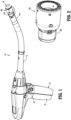
- FIGS. 1 and 2 illustrate a circular stapling device 10 including an exemplary embodiment of the disclosed reload assembly shown generally as reload assembly 100.
- the stapling device 10 includes a handle assembly 12, an elongate body or adaptor assembly 14, the reload assembly 100, and an anvil assembly 18 that is supported for movement in relation to the reload assembly 100 between spaced and approximated positions as is known in the art.
- the reload assembly 100 includes a proximal portion 102 that is releasably coupled to a distal portion 14a of the elongate body 14.
- the handle assembly 12 includes a stationary grip 22 that supports actuation buttons 24 for controlling operation of various functions of the stapling device 10 including approximation of the reload and anvil assemblies 100 and 18, respectively, firing of staples from the reload assembly 100, and cutting or coring of tissue.
- the stapling device 10 is illustrated as an electrically powered stapling device including an electrically powered handle assembly 12 that may support one or more batteries (not shown).
- the elongate body 14 is in the form of an adaptor assembly that translates power from the handle assembly 12 to the reload and anvil assemblies 100, 18, respectively.
- Examples of electrically powered stapling devices can be found in U.S. Patent Nos. 9,055,943 (the ⁇ 943 Patent), 9,023,014 (the ⁇ 014 Patent), and U.S. Publication Nos. 2018/0125495 , and 2017/0340351 .
- the present disclosure could also be incorporated into a manually powered stapling device such as disclosed in U.S. Patent No. 7,303,106 (the ⁇ 106 Patent) or a stapling device that is configured for use with a robotic system such as disclosed in U.S. Patent No. 9,962,159 (the ⁇ 159 Patent) that does not include a handle assembly.
- the reload assembly 100 includes a shell housing 110, a staple actuator 112, a staple pushing member 112a, a knife carrier 114, an annular knife 116 supported on the knife carrier 114, a staple cartridge 118, and a plurality of staples 120 supported within the staple cartridge 118.
- the staple cartridge 118 is annular and defines annular rows of staple pockets 124. Each of the staple pockets 124 supports one of the plurality of staples 120.
- the staple actuator 112 and the staple pushing member 112a together define a longitudinal through-bore 132.
- the staple actuator 112 has a distal portion that abuts a proximal portion of the staple pushing member 112a such that distal movement of the staple actuator 112 within the shell housing 110 causes distal movement of the staple pushing member 112a.
- the staple pushing member 112a of the reload 100 has a plurality of fingers 134. Each of the plurality of fingers 134 is received within a respective one of the staple pockets 124 of the staple cartridge 118 and is movable through the respective staple pocket 124 to eject the staples 120 from the staple pockets 124 when the staple pushing member 130 is moved from a retracted position to an advanced position within the shell housing 110.
- the shell housing 110 includes an outer housing portion 140 and an inner housing portion 142 that are spaced from each other to define an annular cavity 144 between the inner and outer housing portions 140 and 142.
- the staple actuator 112, the staple pushing member 112a, the knife carrier 114, and the annular knife 116 are movable within the annular cavity 144 of the shell housing 110 between retracted and advanced positions.
- the staple actuator 112 and the staple pushing member 112a are movable from their retracted positions to their advanced positions independently of the knife carrier 114 and annular knife 116 to eject the staples 120 from the staple cartridge 118.
- the annular knife 116 defines a cylindrical cavity 117, is supported about an outer surface of the knife carrier 114 and includes a distal cutting edge 117a.
- the knife carrier 114 and annular knife 116 are movable within the through-bore 132 of the staple actuator 112. After the staple actuator 112 and staple pushing member 112a are moved from their retracted positions to their advanced positions, the knife carrier 114 can be moved from its retracted position to its advanced position to cut tissue positioned radially inward of the staple cartridge 118.
- the inner housing portion 142 of the shell housing 110 defines a through-bore 150 ( FIG. 3 ) that receives an anvil shaft (not shown) of the anvil assembly 18.
- the through-bore 150 has a proximal portion that receives a bushing 152 that defines a through-bore 150a that is coaxial and forms an extension of the through-bore 150 of the inner housing portion 142.
- the bushing 152 is formed of a high strength material, e.g., metal, to provide added strength to the inner housing portion 142 of the shell housing 110 and includes an annular flange 151.
- the shell housing 110 includes a proximal portion 158 ( FIG. 3 ) that supports a coupling mechanism 160 ( FIG. 2 ) that is operable to releasably couple the reload assembly 100 to the adaptor assembly 14 of the stapling device 10 ( FIG. 1 ) to facilitate replacement of the reload assembly 100 and reuse of the stapling device 10.
- the coupling mechanism 160 includes a retaining member 162 and a coupling member 164.
- the coupling member 164 is received about the proximal portion 158 ( FIG. 3 ) of the shell housing 110 and is configured to engage the distal portion 14a ( FIG. 1 ) of the adaptor assembly 14 to couple the reload assembly 100 to the adaptor assembly 14. It is envisioned that other coupling mechanisms can be used to secure the reload assembly 100 to the adaptor assembly 14.
- the reload assembly 100 may include an e-prom holder 170 ( FIG. 3 ) that is supported on the shell housing 110 and is configured to support an e-prom (not shown).
- an e-prom can communicate with the adaptor assembly 14 to provide information to the adaptor assembly 14 and the handle assembly 12 related to characteristics of the reload assembly 10.
- the knife carrier 114 is movably positioned within the through-bore 132 ( FIG. 6 ) of the staple actuator 112 and staple pushing member 112a between its retracted and advanced positions and defines a stepped central bore 172.
- the stepped central bore 172 includes a small diameter proximal portion 172a ( FIG. 5 ) and a larger diameter distal portion 172b.
- the proximal portion 172a of the central bore 172 of the knife carrier 114 receives the inner housing portion 142 ( FIG. 8 ) of the shell housing 110 such that the knife carrier 114 slides about the inner housing portion 142.
- the knife carrier 114 defines an annular shoulder 176 ( FIG. 5 ) that is positioned between the proximal portion 172a and the distal portion 172b of the central bore 172.
- the proximal portion 172a of the central bore 172 is defined by longitudinally extending body portions 173 ( FIG. 5 ) that are separated from each other by longitudinal slots 178.
- the longitudinal slots 178 receive guide portions 179 ( FIG. 7 ) of the shell housing 110 to limit the knife carrier 114 to longitudinal movement within the annular cavity 144 of the shell housing 110 as the knife carrier 114 moves between its advanced and retracted positions.
- the proximal portion 172a of knife carrier 114 includes an inner wall surface 115 ( FIG. 5 ) that supports a lockout component 180 ( FIG. 4 ).
- the lockout component 180 includes a resilient body 182 ( FIG. 4 ) that has a distal mounting portion 182a and a proximal locking portion 182b.
- the distal mounting portion 182a of the resilient body 182 is secured to the inner wall 115 of the knife carrier 114 in cantilevered fashion.
- the distal mounting portion 182a defines two openings 184 that receive screws or rivets 186 ( FIG. 5 ) to secure the distal mounting portion 182a of the lockout component 180 to the inner wall surface 115 of the knife carrier 114.
- the lockout component 180 can be secured to the knife carrier 114 using a variety of known attachment techniques.
- the proximal locking portion 182b of the lockout component 180 includes a proximally positioned lockout member 188 and defines a window or opening 190 that is positioned between the lockout member 188 and the distal mounting portion 182a.
- the lockout member 188 is angled inwardly into the central bore 172 of the knife carrier 114 and defines an apex or tip 191.
- the inner housing portion 142 of the shell housing 110 supports a hook component 200 that includes a proximal mounting portion 202 and a body 204 including a hook 206 having a tip or apex 208.
- the mounting portion 202 is an annular member and is received about the bushing 152 between the flange 151 of the bushing 152 and the proximal end 210 of the inner housing portion 142 such that the body 204 including the hook 206 is positioned distally of the mounting portion 202 with the tip 208 of the hook 206 extending in a direction proximally from the body 204.
- the hook component 200 is supported by the mounting portion 202 in cantilevered fashion with the hook 206 biased into engagement with the inner housing portion 142 of the shell housing 110.
- the lockout component 180 when the reload assembly 100 is assembled and the knife carrier 114 is in a retracted position within the shell housing 110, the lockout component 180, which is secured to the inner wall surface 115 of the knife carrier 114, is in a retracted position radially outward of and engaged with the hook component 200 such that the lockout component 180 is biased outwardly of the inner housing portion 142 of the shell housing 110.
- the hook 206 of the hook component 200 is positioned beneath the window 190 of the lockout component 180 and is engaged with the inner housing portion 142 of the shell housing 110.
- the knife carrier 114 is advanced in the direction indicated by arrow "B” to advance the knife 116 in the direction indicted by arrows "C” to cut tissue.
- the lockout component 180 which is secured to the knife carrier 114 moves longitudinally in relation to the hook component 200 in the direction indicated by arrow "D" ( FIG. 13 ).
- the hook 206 of the hook component 200 returns to an unbiased state as the body 204 of the hook component 200 moves radially outwardly from the inner housing portion 142 of the shell housing 110 in the direction indicated by arrow "E" in FIG. 13 .
- the resilient body 182 moves out of engagement with the hook component 200 and inwardly towards its unbiased state in the direction indicated by arrow "F” in FIG. 13 such that the lockout member 188 of the lockout component 180 is engaged with the inner housing portion 142 of the shell housing 110 and is positioned radially inward of the distal end of the body 204 of the hook component 200.
- the above-described structure obstructs readvancement of the knife carrier 114 and the knife 116 to safely retain the knife 116 within the shell housing 110 of the reload assembly 100. This minimizes a risk of injury to a clinician during manipulation and disposal of the reload assembly 200.
- the disclosed reload is described in the context of a powered hand instrument, it is to be understood that the disclosed reload can be adapted for use with robotically controlled systems as well as hand powered instruments.
- the reload can be used with an adaptor 14 that is configured to be coupled to a robotically controlled surgical system.
- the lockout component 200' may be formed with a hook 206' and the hook component 200' may be formed with a body 204' defining a window 190'.
- the distal end of the lockout component 180' is positioned to pass over the lockout member 188'of the component 200' and onto the body 204 of the component 200' after the stapling device 10 ( FIG. 1 ) is fired and the knife carrier 114 ( FIG. 12 ) is retracted such that the hook 206' is received within the window 190'.
- receipt of the hook 206' within the window 190' obstructs readvancement of the knife carrier 114 ( FIG. 12 ) to minimize risk of injury to a clinician during manipulation and disposal of the reload assembly 200.
- FIGS. 18-22 illustrate an alternate embodiment of the disclosed reload assembly shown generally as 300.
- Reload assembly 300 is substantially similar to reload assembly 100 except that the lockout component and the hook component are modified. Only these components are described in further detail herein.
- FIG. 18 illustrates a shell housing 310 of the reload assembly 300 ( FIG. 20 ) which includes an outer housing portion 340, an inner housing portion 342, and guide portions 379.
- the guide portions 379 are positioned between the outer housing portion 340 and the inner housing portion 342.
- At least one of the guide portions 379 supports a first locking component 402.
- the first locking component 402 includes resilient body 404 having a hook 406 that extends radially outward from the respective guide portion 379.
- FIGS. 18 and 19 illustrate the shell housing 310 and the knife carrier 314 of the reload assembly 300.
- the knife carrier 314 includes longitudinally extending body portions 373 that define a central bore 372.
- the longitudinally extending body portions 373 are separated from each other by longitudinal slots 378 that receive the guide portions 379 ( FIG. 18 ) of the shell housing 310 to limit the knife carrier 314 to longitudinal movement within the shell housing 310 as the knife carrier 314 moves between advanced and retracted positions.
- the proximal portion of knife carrier 314 includes an inner wall surface 315 that supports a second locking component 380 ( FIG. 19 ).
- the second locking component 380 is formed from a resilient material and includes a proximal end having a second hook 382 that extends radially inward into the central bore 372 of the knife carrier 314.
- the first and second locking components 402 and 380 are formed from leaf springs.
- a side of the first locking component 402 opposite to the hook 406 is engaged with a side of the second locking component 380 opposite the hook 382.
- the first locking component 402 is aligned and engaged with the second locking component 380 with the hooks 406 and 382 of the first and second locking components 402 and 380 facing away from each other to allow advancement of the knife carrier 314 and knife 316 in relation to the inner housing portion 342 of the shell housing 310.
- the second locking component 380 moves in relation to the first locking component 402 such that the tapered surfaces 406a and 382a of the hooks 406 and 382 engage each other, deform, and pass by each other.
- the hooks 406 and 380 are aligned with each other to obstruct movement of the knife carrier 314 and knife 316 back to their advanced positions.
- the above-described structure obstructs readvancement of the knife carrier 314 and the knife 316 to safely retain the knife 316 within the shell housing 310 of the reload assembly 300. This minimizes a risk of injury to a clinician during manipulation and disposal of the reload assembly 300.
Description
- The present disclosure is directed to circular stapling devices and, more particularly, to reload assemblies for circular stapling devices with structure to retain a knife carrier in a retracted position after the stapling device is fired.
- Conventional circular stapling devices include an elongate body and a shell or reload assembly that is supported on a distal portion of the elongate body. The reload assembly includes a shell housing, a staple cartridge supported on the shell housing having a plurality of staples, a pusher assembly, a knife defining a cylindrical cavity, and a knife carrier that supports the knife. The pusher assembly includes an annular pusher and a staple pushing member that is engaged with the annular pusher and is movable to move the staple pushing member to eject staples from the staple cartridge. The knife carrier is movable to advance the knife through the staple cartridge to core or cut tissue
- After a stapling device has been operated to staple and cut tissue, the knife carrier and the knife are retracted to withdraw the knife into the shell housing. This serves two purposes. The first purpose is to move the knife to a position to allow removal of a tissue donut from within the cavity defined by the knife. The second purpose is to position the knife in a location recessed within the shell housing to avoid injury to a clinician during manipulation and disposal of the reload assembly.
In some instances, the tissue donut is compressed within the cavity defined by the knife to such a degree that removal of the tissue donut from within the cavity defined by the knife is difficult. A continuing need exists in the art for a reload assembly that includes improved structure for retaining the knife/knife carrier in a retracted position.EP2614785A2 describes a circular stapler including a stapling forming assembly that is actuated independently from actuation of the cutting assembly. The circular stapler includes a handle assembly, an elongate body extending from the handle assembly, and a cartridge assembly mounted on a distal end of the elongate body. The cartridge assembly includes a pusher assembly and a knife assembly. The knife assembly is selectively fixed relative to the pusher assembly for independent movement relative to the pusher assembly. A knife is initially detached from a knife pusher in a first stroke, and subsequently attached to the knife pusher in a second stroke. A pusher assembly and a knife assembly may also be included, and are selectively received between inner and outer cylindrical portions of a housing. The inner cylindrical portion may include a plurality of longitudinal grooves on an outer surface thereof configured to operably receive the knife assembly. The inner cylindrical portion may include a detent in each of the plurality of longitudinal grooves configured to selectively engage the knife assembly. In one embodiment the pusher assembly and the knife assembly are substantially cylindrical. - The present invention is defined in the independent claims. Certain optional features thereof are defined in the dependent claims. The only protection sought is for the invention as claimed. One aspect of the disclosure is directed to a reload assembly including a shell housing, a staple cartridge, a pusher, a knife carrier, a lockout component, and a hook component. The shell housing includes an inner housing portion and an outer housing portion that is spaced from the inner housing portion to define an annular cavity between the inner and outer housing portions. The staple cartridge is supported on a distal portion of the shell housing and defines a plurality of staple pockets that receive staples. The pusher is supported within the annular cavity of the shell housing and is movable between a retracted position and an advanced position to eject the staples from the staple cartridge. The knife carrier includes a body that defines a longitudinal axis and supports a knife. The body of the knife carrier includes an inner wall defining a central bore. The inner housing portion of the shell housing is positioned within the central bore of the knife carrier such that the knife carrier is movable about the inner housing portion of the shell housing between advanced and retracted positions. The lockout component is supported on the inner wall of the knife carrier, has a body formed of a resilient material, and defines a window. The hook component is supported on the inner housing portion of the shell housing and includes a body having a hook that is received within the window of the lockout component when the knife carrier is in its retracted position after the reload assembly has been fired to obstruct readvancement of the knife carrier.
- In embodiments, the lockout component includes a resilient body that has a lockout member positioned proximally of the window, wherein the resilient body is positioned between the hook component and the knife carrier when the knife carrier is in a retracted position prior to firing of the reload assembly.
- In some embodiments, the hook is angled downwardly towards the inner housing portion of the shell housing.
- In certain embodiments, the hook component includes a proximal mounting portion that is secured to the inner housing portion such that the hook component is supported in cantilevered fashion to the inner housing portion of the shell housing.
- In embodiments, the lockout component is positioned to pass between the hook component and the inner housing portion of the shell housing when the knife carrier is returned from its advanced position to its retracted position after the reload assembly has been fired to position the hook of the hook component within the window of the lockout component.
- In some embodiments, the lockout component includes a distal mounting portion that is secured to the inner wall of the knife carrier to secure the lockout component to the knife carrier in cantilevered fashion.
- In certain embodiments, the hook of the hook component has a proximal portion connected to the body and a tip that engages the inner housing portion of the shell assembly, wherein the tip is positioned proximally of the proximal portion of the hook.
- Another aspect of the disclosure is directed to a reload assembly including a shell housing, a staple cartridge, a knife carrier, a first locking component, and a second locking component. The shell housing includes an inner housing portion, an outer housing portion, and at least one guide portion positioned between the inner and outer housing portions. The inner housing portion is spaced from the outer housing portion to define an annular cavity between the inner and outer housing portions. The staple cartridge is supported on a distal portion of the shell housing and defines a plurality of staple pockets that receive staples. The knife carrier includes a body defining a longitudinal axis and supporting a knife. The body of the knife carrier includes a plurality of longitudinally extending body portions that are spaced from each other to define longitudinal slots that receive the at least one guide portion of the shell housing. The longitudinally extending portions include inner walls that define a central bore. The inner housing portion of the shell housing is positioned within the central bore of the knife carrier such that the knife carrier is movable about the inner housing portion of the shell housing between advanced and retracted positions. The first locking component is supported on the at least one guide portion of the shell housing and includes a resilient body having a first hook that extends radially outward of the at least one guide portion. The second locking component is supported on the inner wall of the knife carrier and includes a body formed from a resilient material having a second hook that extends radially inward into the central bore of the knife carrier. When the knife carrier is in a pre-fired retracted position, the second locking component is positioned between the first locking component and the at least one guide portion of the shell housing such that the first and second hooks are misaligned, and when the knife carrier is in a post-fired retracted position, the second hook component is positioned radially outward of the first hook component such that the first and second hooks are aligned to obstruct readvancement of the knife carrier.
- In embodiments, the first and second locking components are formed of leaf springs.
- In some embodiments, the first hook of the first locking component includes a distal portion having a distally facing tapered surface and the second hook of the second locking component includes a proximal portion having a proximally facing tapered surface, wherein the distally facing tapered surface engages the proximally facing tapered surface as the knife carrier is moved from its advanced position to its retracted position to allow the second locking component to pass over the first locking component.
- Various embodiments of the disclosed reload assembly are described herein below with reference to the drawings, wherein:
-
FIG. 1 is a side perspective view of a circular stapling device including an exemplary embodiment of the disclosed reload assembly in accordance with the present disclosure; -
FIG. 2 is a side perspective view of the reload assembly ofFIG. 1 ; -
FIG. 3 is an exploded side perspective view of the reload assembly ofFIG. 2 ; -
FIG. 4 is an enlarged view of the indicated area of detail shown inFIG. 3 ; -
FIG. 5 is a cross-sectional view of a knife carrier of the reload assembly shown inFIG. 3 ; -
FIG. 6 is an enlarged view of the indicated area of detail shown inFIG. 3 ; -
FIG. 7 is a perspective, cross-sectional view of the reload assembly shown inFIG. 3 taken through the longitudinal axis of the reload assembly with the reload assembly in a pre-fired condition; -
FIG. 8 is a cross-sectional view of the reload assembly shown inFIG. 3 taken through the longitudinal axis of the reload assembly with the reload assembly in a pre-fired condition; -
FIG. 9 is an enlarged view of the indicated area of detail shown inFIG. 8 ; -
FIG. 10 is a cross-sectional view taken along section line 10-10 ofFIG. 9 ; -
FIG. 11 is a side perspective view of a lockout component of the reload assembly shown inFIG. 3 ; -
FIG. 12 is a cross-sectional view of the reload assembly shown inFIG. 3 taken through the longitudinal axis of the reload assembly with the reload assembly in a fired condition and the knife carrier in an advanced position; -
FIG. 13 is an enlarged view of the indicated area of detail shown inFIG. 12 ; -
FIG. 14 is a cross-sectional view of the reload assembly shown inFIG. 3 taken through the longitudinal axis of the reload assembly with the reload assembly in a fired condition and the knife carrier in the retracted position; -
FIG. 15 is an enlarged view of the indicated area of detail shown inFIG. 14 ; -
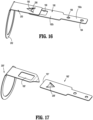
FIG. 16 is a side perspective view of the interaction between the locking component and the hook component of the reload assembly shown inFIG. 14 with the locking component and the hook component in a locked position; -
FIG. 17 is a side perspective view of another exemplary embodiment of the disclosed locking component and hook component of the reload assembly shown inFIG. 3 ; -
FIG. 18 is a perspective, cross-sectional view of a shell housing of another exemplary embodiment of the disclosed reload assembly of the stapling device shown inFIG. 1 with a locking component secured to an inner housing portion of the shell housing; -
FIG. 19 is a perspective, cross-sectional view of the knife carrier of another exemplary embodiment of the disclosed reload assembly with a lock component secured to a body of the knife carrier; -
FIG. 20 is a cross-sectional view of a reload assembly including the locking component and hook component shown inFIGS. 18 and 19 , respectively, with the reload assembly in a pre-fired condition; -
FIG. 21 is a cross-sectional view of the reload assembly shown inFIG. 20 with the reload assembly in a fired condition and the knife carrier in an advanced position; and -
FIG. 22 is a cross-sectional view of the reload assembly shown inFIG. 20 with the reload assembly in a fired condition and the knife carrier in a retracted position. - The disclosed reload assembly will now be described in detail with reference to the drawings in which like reference numerals designate identical or corresponding elements in each of the several views. However, it is to be understood that the disclosed embodiments are merely exemplary of the disclosure and may be embodied in various forms. Well-known functions or constructions are not described in detail to avoid obscuring the present disclosure in unnecessary detail. Therefore, specific structural and functional details disclosed herein are not to be interpreted as limiting, but merely as a basis for the claims and as a representative basis for teaching one skilled in the art to variously employ the present disclosure in virtually any appropriately detailed structure. In addition, directional terms such as front, rear, upper, lower, top, bottom, distal, proximal, and similar terms are used to assist in understanding the description and are not intended to limit the present disclosure.
- In this description, the term "proximal" is used generally to refer to that portion of the device that is closer to a clinician, while the term "distal" is used generally to refer to that portion of the device that is farther from the clinician. In addition, the term "endoscopic" is generally used to refer to endoscopic, laparoscopic, arthroscopic, and/or any other procedure conducted through small diameter incision or cannula. Further, the term "clinician" is used generally to refer to medical personnel including doctors, nurses, and support personnel.
-
FIGS. 1 and 2 illustrate acircular stapling device 10 including an exemplary embodiment of the disclosed reload assembly shown generally as reloadassembly 100. The staplingdevice 10 includes ahandle assembly 12, an elongate body oradaptor assembly 14, the reloadassembly 100, and ananvil assembly 18 that is supported for movement in relation to the reloadassembly 100 between spaced and approximated positions as is known in the art. The reloadassembly 100 includes aproximal portion 102 that is releasably coupled to adistal portion 14a of theelongate body 14. Thehandle assembly 12 includes astationary grip 22 that supportsactuation buttons 24 for controlling operation of various functions of the staplingdevice 10 including approximation of the reload andanvil assemblies assembly 100, and cutting or coring of tissue. - The stapling
device 10 is illustrated as an electrically powered stapling device including an electricallypowered handle assembly 12 that may support one or more batteries (not shown). Theelongate body 14 is in the form of an adaptor assembly that translates power from thehandle assembly 12 to the reload andanvil assemblies U.S. Patent Nos. 9,055,943 9,023,014 U.S. Publication Nos. 2018/0125495 , and2017/0340351 . Alternately, it is envisioned that the present disclosure could also be incorporated into a manually powered stapling device such as disclosed inU.S. Patent No. 7,303,106 (the `106 Patent) or a stapling device that is configured for use with a robotic system such as disclosed inU.S. Patent No. 9,962,159 - Referring to
FIGS. 2 and3 , the reloadassembly 100 includes ashell housing 110, astaple actuator 112, astaple pushing member 112a, aknife carrier 114, anannular knife 116 supported on theknife carrier 114, astaple cartridge 118, and a plurality ofstaples 120 supported within thestaple cartridge 118. Thestaple cartridge 118 is annular and defines annular rows of staple pockets 124. Each of the staple pockets 124 supports one of the plurality ofstaples 120. Thestaple actuator 112 and thestaple pushing member 112a together define a longitudinal through-bore 132. Thestaple actuator 112 has a distal portion that abuts a proximal portion of thestaple pushing member 112a such that distal movement of thestaple actuator 112 within theshell housing 110 causes distal movement of thestaple pushing member 112a. Thestaple pushing member 112a of the reload 100 has a plurality offingers 134. Each of the plurality offingers 134 is received within a respective one of the staple pockets 124 of thestaple cartridge 118 and is movable through the respectivestaple pocket 124 to eject thestaples 120 from the staple pockets 124 when the staple pushing member 130 is moved from a retracted position to an advanced position within theshell housing 110. - The
shell housing 110 includes anouter housing portion 140 and aninner housing portion 142 that are spaced from each other to define anannular cavity 144 between the inner andouter housing portions staple actuator 112, thestaple pushing member 112a, theknife carrier 114, and theannular knife 116 are movable within theannular cavity 144 of theshell housing 110 between retracted and advanced positions. Thestaple actuator 112 and thestaple pushing member 112a are movable from their retracted positions to their advanced positions independently of theknife carrier 114 andannular knife 116 to eject thestaples 120 from thestaple cartridge 118. Theannular knife 116 defines acylindrical cavity 117, is supported about an outer surface of theknife carrier 114 and includes adistal cutting edge 117a. Theknife carrier 114 andannular knife 116 are movable within the through-bore 132 of thestaple actuator 112. After thestaple actuator 112 andstaple pushing member 112a are moved from their retracted positions to their advanced positions, theknife carrier 114 can be moved from its retracted position to its advanced position to cut tissue positioned radially inward of thestaple cartridge 118. - The
inner housing portion 142 of theshell housing 110 defines a through-bore 150 (FIG. 3 ) that receives an anvil shaft (not shown) of theanvil assembly 18. For a more detailed description of anexemplary anvil assembly 18, see, e.g., the ` 106 Patent. The through-bore 150 has a proximal portion that receives abushing 152 that defines a through-bore 150a that is coaxial and forms an extension of the through-bore 150 of theinner housing portion 142. In embodiments, thebushing 152 is formed of a high strength material, e.g., metal, to provide added strength to theinner housing portion 142 of theshell housing 110 and includes anannular flange 151. - The
shell housing 110 includes a proximal portion 158 (FIG. 3 ) that supports a coupling mechanism 160 (FIG. 2 ) that is operable to releasably couple the reloadassembly 100 to theadaptor assembly 14 of the stapling device 10 (FIG. 1 ) to facilitate replacement of the reloadassembly 100 and reuse of the staplingdevice 10. Thecoupling mechanism 160 includes a retainingmember 162 and acoupling member 164. Thecoupling member 164 is received about the proximal portion 158 (FIG. 3 ) of theshell housing 110 and is configured to engage thedistal portion 14a (FIG. 1 ) of theadaptor assembly 14 to couple the reloadassembly 100 to theadaptor assembly 14. It is envisioned that other coupling mechanisms can be used to secure the reloadassembly 100 to theadaptor assembly 14. - The reload
assembly 100 may include an e-prom holder 170 (FIG. 3 ) that is supported on theshell housing 110 and is configured to support an e-prom (not shown). As is known in the art, an e-prom can communicate with theadaptor assembly 14 to provide information to theadaptor assembly 14 and thehandle assembly 12 related to characteristics of the reloadassembly 10. - Referring to
FIGS. 3-5 , theknife carrier 114 is movably positioned within the through-bore 132 (FIG. 6 ) of thestaple actuator 112 andstaple pushing member 112a between its retracted and advanced positions and defines a steppedcentral bore 172. The steppedcentral bore 172 includes a small diameterproximal portion 172a (FIG. 5 ) and a larger diameterdistal portion 172b. Theproximal portion 172a of thecentral bore 172 of theknife carrier 114 receives the inner housing portion 142 (FIG. 8 ) of theshell housing 110 such that theknife carrier 114 slides about theinner housing portion 142. - The
knife carrier 114 defines an annular shoulder 176 (FIG. 5 ) that is positioned between theproximal portion 172a and thedistal portion 172b of thecentral bore 172. Theproximal portion 172a of thecentral bore 172 is defined by longitudinally extending body portions 173 (FIG. 5 ) that are separated from each other bylongitudinal slots 178. Thelongitudinal slots 178 receive guide portions 179 (FIG. 7 ) of theshell housing 110 to limit theknife carrier 114 to longitudinal movement within theannular cavity 144 of theshell housing 110 as theknife carrier 114 moves between its advanced and retracted positions. Theproximal portion 172a ofknife carrier 114 includes an inner wall surface 115 (FIG. 5 ) that supports a lockout component 180 (FIG. 4 ). - In embodiments, the
lockout component 180 includes a resilient body 182 (FIG. 4 ) that has adistal mounting portion 182a and aproximal locking portion 182b. Thedistal mounting portion 182a of theresilient body 182 is secured to theinner wall 115 of theknife carrier 114 in cantilevered fashion. In embodiments, thedistal mounting portion 182a defines twoopenings 184 that receive screws or rivets 186 (FIG. 5 ) to secure thedistal mounting portion 182a of thelockout component 180 to theinner wall surface 115 of theknife carrier 114. Alternately, thelockout component 180 can be secured to theknife carrier 114 using a variety of known attachment techniques. Theproximal locking portion 182b of thelockout component 180 includes a proximally positionedlockout member 188 and defines a window or opening 190 that is positioned between thelockout member 188 and thedistal mounting portion 182a. In embodiments, thelockout member 188 is angled inwardly into thecentral bore 172 of theknife carrier 114 and defines an apex ortip 191. - Referring to
FIGS. 6-8 , theinner housing portion 142 of theshell housing 110 supports ahook component 200 that includes a proximal mountingportion 202 and abody 204 including ahook 206 having a tip orapex 208. In embodiments, the mountingportion 202 is an annular member and is received about thebushing 152 between theflange 151 of thebushing 152 and theproximal end 210 of theinner housing portion 142 such that thebody 204 including thehook 206 is positioned distally of the mountingportion 202 with thetip 208 of thehook 206 extending in a direction proximally from thebody 204. In embodiments, thehook component 200 is supported by the mountingportion 202 in cantilevered fashion with thehook 206 biased into engagement with theinner housing portion 142 of theshell housing 110. - Referring to
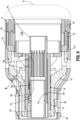
FIGS. 8-11 , when the reloadassembly 100 is assembled and theknife carrier 114 is in a retracted position within theshell housing 110, thelockout component 180, which is secured to theinner wall surface 115 of theknife carrier 114, is in a retracted position radially outward of and engaged with thehook component 200 such that thelockout component 180 is biased outwardly of theinner housing portion 142 of theshell housing 110. In this position, thehook 206 of thehook component 200 is positioned beneath thewindow 190 of thelockout component 180 and is engaged with theinner housing portion 142 of theshell housing 110. - Referring to
FIGS. 12 and13 , after thestaple actuator 112 and thestaple pushing member 112a are advanced in the direction indicated by arrows "A" to drive thestaples 120 from thestaple cartridge 118 into theanvil assembly 18, theknife carrier 114 is advanced in the direction indicated by arrow "B" to advance theknife 116 in the direction indicted by arrows "C" to cut tissue. When theknife carrier 114 advances in direction "B", thelockout component 180 which is secured to theknife carrier 114 moves longitudinally in relation to thehook component 200 in the direction indicated by arrow "D" (FIG. 13 ). When thelockout member 188 of thelockout component 180 moves to a position distally of thehook component 200, thehook 206 of thehook component 200 returns to an unbiased state as thebody 204 of thehook component 200 moves radially outwardly from theinner housing portion 142 of theshell housing 110 in the direction indicated by arrow "E" inFIG. 13 . In addition, when thelockout member 188 of thelockout component 180 moves distally of thehook component 200, theresilient body 182 moves out of engagement with thehook component 200 and inwardly towards its unbiased state in the direction indicated by arrow "F" inFIG. 13 such that thelockout member 188 of thelockout component 180 is engaged with theinner housing portion 142 of theshell housing 110 and is positioned radially inward of the distal end of thebody 204 of thehook component 200. - Referring to
FIGS. 14-17 , when theknife carrier 114 is moved back to its retracted position after the reloadassembly 100 is fired in the direction indicated by arrow "G" inFIGS. 14 and15 , thelockout member 188 of the lockout component moves under thebody 204 of thehook component 200 and engages thehook 206 of thehook component 200. When thelockout member 188 engages thehook 206, thebody 204 of thehook component 200 is biased radially outward of theinner housing portion 142 in the direction indicated by arrow "H" such that thelockout member 188 passes under thehook 206 and thehook 206 moves through thewindow 190 of thelockout component 180 such that the tip 191of thelockout member 188 moves into engagement with theinner housing portion 142 of theshell housing 110. In this position, engagement between thehook 206 and the proximal portion of thebody 182 of thelockout component 180 that defines thewindow 190 obstructs readvancement of thehook component 200 to obstruct readvancement of theknife carrier 114 andknife 116. - The above-described structure obstructs readvancement of the
knife carrier 114 and theknife 116 to safely retain theknife 116 within theshell housing 110 of the reloadassembly 100. This minimizes a risk of injury to a clinician during manipulation and disposal of the reloadassembly 200. - Although the disclosed reload is described in the context of a powered hand instrument, it is to be understood that the disclosed reload can be adapted for use with robotically controlled systems as well as hand powered instruments. For example, the reload can be used with an
adaptor 14 that is configured to be coupled to a robotically controlled surgical system. - Referring to
FIG. 17 , in an alternate embodiment, the lockout component 200' may be formed with a hook 206' and the hook component 200' may be formed with a body 204' defining a window 190'. The distal end of the lockout component 180' is positioned to pass over the lockout member 188'of the component 200' and onto thebody 204 of the component 200' after the stapling device 10 (FIG. 1 ) is fired and the knife carrier 114 (FIG. 12 ) is retracted such that the hook 206' is received within the window 190'. As discussed above with regard to the reload 100 (FIG. 3 ), receipt of the hook 206' within the window 190' obstructs readvancement of the knife carrier 114 (FIG. 12 ) to minimize risk of injury to a clinician during manipulation and disposal of the reloadassembly 200. -
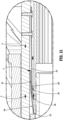
FIGS. 18-22 illustrate an alternate embodiment of the disclosed reload assembly shown generally as 300. Reloadassembly 300 is substantially similar to reloadassembly 100 except that the lockout component and the hook component are modified. Only these components are described in further detail herein. -
FIG. 18 illustrates ashell housing 310 of the reload assembly 300 (FIG. 20 ) which includes anouter housing portion 340, aninner housing portion 342, and guideportions 379. Theguide portions 379 are positioned between theouter housing portion 340 and theinner housing portion 342. At least one of theguide portions 379 supports afirst locking component 402. Thefirst locking component 402 includesresilient body 404 having ahook 406 that extends radially outward from therespective guide portion 379. -
FIGS. 18 and 19 illustrate theshell housing 310 and theknife carrier 314 of the reloadassembly 300. Theknife carrier 314 includes longitudinally extendingbody portions 373 that define acentral bore 372. The longitudinally extendingbody portions 373 are separated from each other bylongitudinal slots 378 that receive the guide portions 379 (FIG. 18 ) of theshell housing 310 to limit theknife carrier 314 to longitudinal movement within theshell housing 310 as theknife carrier 314 moves between advanced and retracted positions. - The proximal portion of
knife carrier 314 includes aninner wall surface 315 that supports a second locking component 380 (FIG. 19 ). Thesecond locking component 380 is formed from a resilient material and includes a proximal end having asecond hook 382 that extends radially inward into thecentral bore 372 of theknife carrier 314. In embodiments, the first andsecond locking components - When the reload
assembly 300 is in a pre-fired position and theknife carrier 314 is in its retracted position as shown inFIG. 20 , a side of thefirst locking component 402 opposite to thehook 406 is engaged with a side of thesecond locking component 380 opposite thehook 382. In this position, thefirst locking component 402 is aligned and engaged with thesecond locking component 380 with thehooks second locking components knife carrier 314 andknife 316 in relation to theinner housing portion 342 of theshell housing 310. - When the
knife carrier 314 is advanced in the direction indicated by arrows "J" inFIG. 21 about theinner housing portion 342 of theshell housing 310 to advance thesecond locking component 380 to a position distally of thefirst locking component 402, the first andsecond locking components first locking component 402 returns in the direction indicated by arrow "L" to its unbiased state in which the side of thefirst locking component 402 opposite to thefirst hook 406 is positioned against theguide 379. Similarly, thesecond locking component 380 returns in the direction indicated by arrow "M" to its unbiased state in which the side of thesecond locking component 380 opposite to thehook 382 is positioned against theinner wall surface 315 of theknife carrier 314. When the first andsecond locking components surfaces hooks - When the
knife carrier 314 is moved from its advanced position back to its retracted position in the direction indicated by arrows "N" (FIG. 22 ) after the stapling device 10 (FIG. 1 ) has been fired and the knife has been advanced to cut tissue disposed between theanvil assembly 18 and thestaple cartridge 118, thesecond locking component 380 moves in relation to thefirst locking component 402 such that thetapered surfaces hooks knife carrier 114 is in its retracted position, thehooks knife carrier 314 andknife 316 back to their advanced positions. - The above-described structure obstructs readvancement of the
knife carrier 314 and theknife 316 to safely retain theknife 316 within theshell housing 310 of the reloadassembly 300. This minimizes a risk of injury to a clinician during manipulation and disposal of the reloadassembly 300.
Claims (10)
- A reload assembly (100) comprising:a shell housing (110) including an inner housing portion (142) and an outer housing portion (140) , the inner housing portion (142) spaced from the outer housing portion (140) to define an annular cavity (144) between the inner and outer housing portions (142, 140);a staple cartridge (118) supported on a distal portion of the shell housing (110), the staple cartridge (118) having a plurality of staple pockets (124), each of the staple pockets (124) supporting a staple (120);a pusher (112a) supported within the annular cavity (144), the pusher (112a) movable between a retracted position and an advanced position to eject the staples (120) from the staple cartridge (118);a knife carrier (114) including a body defining a longitudinal axis and supporting a knife (116), the body of the knife carrier (114) including an inner wall (115) defining a central bore (172), the inner housing portion (142) of the shell housing (110) being positioned within the central bore of the knife carrier (114) such that the knife carrier (114) is movable about the inner housing portion (142) of the shell housing (110) between advanced and retracted positions;a lockout component (180) supported on the inner wall (115) of the knife carrier (114), the lockout component (180) having a body (182) formed of a resilient material and defining a window (190); andcharacterized by a hook component (200) supported on the inner housing portion (142) of the shell housing (110) and including a body (204) having a hook (206) that is received within the window (190) of the lockout component (180) when the knife carrier (114) is in its retracted position after the reload assembly (100) is fired to obstruct movement of the knife carrier (114) back to its advanced position.
- The reload assembly (100) of claim 1, wherein the lockout component (180) includes a resilient body (182) having a lockout member (188) positioned proximally of the window (190), the resilient body (182) being positioned between the hook component (200) and the knife carrier (114) when the knife carrier (114) is in a retracted position prior to firing of the reload assembly (100).
- The reload assembly (100) of claim 2, wherein the hook (206) is angled downwardly towards the inner housing portion (142) of the shell housing (110).
- The reload assembly (100) of claim 3, wherein the hook component (200) includes a proximal mounting portion (202) that is secured to the inner housing portion (142) such that the hook component (200) is supported in cantilevered fashion to the inner housing portion (142) of the shell housing (110).
- The reload assembly (100) of claim 4, wherein the lockout component (180) is positioned to pass between the hook component (200) and the inner housing portion (142) of the shell housing (110) when the knife carrier (114) is returned from its advanced position to its retracted position after the reload assembly (100) is fired to position the hook (206) of the hook component (200) within the window (190) of the lockout component (180).
- The reload assembly (100) of claim 5, wherein the lockout component (180) includes a distal mounting portion (182a) that is secured to the inner wall (115) of the knife carrier (114) to secure the lockout component (180) to the knife carrier (114) in cantilevered fashion.
- The reload assembly (100) of claim 6, wherein the hook of the hook component (200) has a proximal portion connected to the body (204) and a tip (208) that engages the inner housing portion (142) of the shell assembly (110), the tip (208) being positioned proximally of the proximal portion of the hook (206).
- A reload assembly (300) comprising:a shell housing (310) including an inner housing portion (342), an outer housing portion (340), and at least one guide portion (379) positioned between the inner and outer housing portions, (342, 340) the inner housing portion (342) spaced from the outer housing portion (340) to define an annular cavity (144) between the inner and outer housing portions (342, 340);a staple cartridge (118) supported on a distal portion of the shell housing (310), the staple cartridge (118) defining a plurality of staple pockets (124), each of the staple pockets (124) supporting a staple (120);a knife carrier (314) including a body defining a longitudinal axis and supporting a knife (316), the body of the knife carrier (314) including a plurality of longitudinally extending body portions (373) that are spaced from each other to define longitudinal slots (378), the longitudinal slots (378) receiving the at least one guide portion (379) of the shell housing (310), an inner wall (315) of the longitudinally extending portions (373) defining a central bore (372), the inner housing portion (142) of the shell housing (110) being positioned within the central bore (372) of the knife carrier (314) such that the knife carrier (314) is movable about the inner housing portion (342) of the shell housing (310) between advanced and retracted positions; characterized bya first locking component (402) supported on the at least one guide portion (379) of the shell housing (310), the first locking component (402) including a resilient body (404) having a first hook (406) that extends radially outward of the at least one guide portion (379); anda second locking component (380) supported on the inner wall of the knife carrier (314), the second locking component (380) including a body formed from a resilient material having a second hook (382) that extends radially inward into the central bore (372) of the knife carrier (314);wherein when the knife carrier (314) is in a pre-fired retracted position, the second locking component (380) is positioned between the first locking component (402) and the at least one guide portion (379) of the shell housing (310) such that the first and second hooks (406, 382) are misaligned and when the knife carrier (314) is in a post-fired retracted position, the second hook (382) is positioned radially outward of the first hook (406) such that the first and second hooks (406, 382) are aligned to obstruct readvancement of the knife carrier (314) .
- The reload assembly of claim 8, wherein the first and second locking components (402, 380) are formed of leaf springs.
- The reload assembly of claim 8 or claim 9, wherein the first hook (406) of the first locking component (402) includes a distal portion having a distally facing tapered surface (406a) and the second hook (382) of the second locking component (380) includes a proximal portion having a proximally facing tapered surface (382a), the distally facing tapered surface (406a) engaging the proximally facing tapered surface (382a) as the knife carrier (314) is moved from the advanced position to the retracted to allow the second locking component (380) to pass over the first locking component (402).
Applications Claiming Priority (2)
| Application Number | Priority Date | Filing Date | Title |
|---|---|---|---|
| US201962874534P | 2019-07-16 | 2019-07-16 | |
| US16/878,094 US11192227B2 (en) | 2019-07-16 | 2020-05-19 | Reload assembly for circular stapling devices |
Publications (2)
| Publication Number | Publication Date |
|---|---|
| EP3766434A1 EP3766434A1 (en) | 2021-01-20 |
| EP3766434B1 true EP3766434B1 (en) | 2023-10-25 |
Family
ID=71575186
Family Applications (1)
| Application Number | Title | Priority Date | Filing Date |
|---|---|---|---|
| EP20185269.6A Active EP3766434B1 (en) | 2019-07-16 | 2020-07-10 | Reload assembly for circular stapling devices |
Country Status (3)
| Country | Link |
|---|---|
| US (2) | US11192227B2 (en) |
| EP (1) | EP3766434B1 (en) |
| CN (1) | CN112237456A (en) |
Families Citing this family (4)
| Publication number | Priority date | Publication date | Assignee | Title |
|---|---|---|---|---|
| US11065005B2 (en) * | 2018-11-07 | 2021-07-20 | Covidien Lp | Reload assembly for a circular stapling device |
| US11331782B2 (en) * | 2019-03-01 | 2022-05-17 | Covidien Lp | Reload assembly for a circular stapling device |
| US11357509B2 (en) * | 2019-07-11 | 2022-06-14 | Covidien Lp | Reload assembly for a circular stapling device |
| US11192227B2 (en) | 2019-07-16 | 2021-12-07 | Covidien Lp | Reload assembly for circular stapling devices |
Family Cites Families (355)
| Publication number | Priority date | Publication date | Assignee | Title |
|---|---|---|---|---|
| CA908529A (en) | 1972-08-29 | V. Astafiev Georgy | Surgical instrument for suturing hollow organs in infants | |
| DE1057729B (en) | 1954-03-29 | 1959-05-21 | Lameris Instr N V | Surgical device for connecting two parts of the intestine |
| GB787043A (en) | 1954-09-15 | 1957-11-27 | Sylvania Electric Prod | Method for production of silicon |
| CA736256A (en) | 1962-08-27 | 1966-06-14 | S. Kasoolin Viacheslav | Instrument for suturing esophagus to intestine or stomach |
| FR1461464A (en) | 1965-08-20 | 1966-02-25 | Niiex Khirurgicheskoi Apparatu | Surgical device for suturing organs |
| CH470170A (en) | 1968-02-02 | 1969-03-31 | Vnii Khirurgicheskoi Apparatur | Device for applying round anastomoses |
| US3638652A (en) | 1970-06-01 | 1972-02-01 | James L Kelley | Surgical instrument for intraluminal anastomosis |
| US3771526A (en) | 1972-02-07 | 1973-11-13 | P Rudie | Anastomosis clamp |
| US4603693A (en) | 1977-05-26 | 1986-08-05 | United States Surgical Corporation | Instrument for circular surgical stapling of hollow body organs and disposable cartridge therefor |
| US4573468A (en) | 1977-05-26 | 1986-03-04 | United States Surgical Corporation | Hollow body organ stapling instrument and disposable cartridge employing relief vents |
| US4304236A (en) | 1977-05-26 | 1981-12-08 | United States Surgical Corporation | Stapling instrument having an anvil-carrying part of particular geometric shape |
| NL7711347A (en) | 1977-10-17 | 1979-04-19 | Carl Robert Erik Daantje | Stapling instrument for joining intestine ends - has head coupling rod in two parts screwing together with hand grip |
| US4207898A (en) | 1978-03-27 | 1980-06-17 | Senco Products, Inc. | Intralumenal anastomosis surgical stapling instrument |
| US4198982A (en) | 1978-03-31 | 1980-04-22 | Memorial Hospital For Cancer And Allied Diseases | Surgical stapling instrument and method |
| DE2947107A1 (en) | 1978-12-07 | 1980-06-26 | United States Surgical Corp | ACCURATELY ALIGNED CARTRIDGE AND INSTRUMENT FOR CLAMPING ANASTOMOSES |
| SU1088712A1 (en) | 1979-11-14 | 1984-04-30 | Всесоюзный научно-исследовательский и испытательный институт медицинской техники | Apparatus for circular suture of blood vessels |
| AU534210B2 (en) | 1980-02-05 | 1984-01-12 | United States Surgical Corporation | Surgical staples |
| US4319576A (en) | 1980-02-26 | 1982-03-16 | Senco Products, Inc. | Intralumenal anastomosis surgical stapling instrument |
| US4289133A (en) | 1980-02-28 | 1981-09-15 | Senco Products, Inc. | Cut-through backup washer for the scalpel of an intraluminal surgical stapling instrument |
| US4606343A (en) | 1980-08-18 | 1986-08-19 | United States Surgical Corporation | Self-powered surgical fastening instrument |
| US4351466A (en) | 1980-10-16 | 1982-09-28 | United States Surgical Corporation | Disposable instrument for surgical fastening |
| US4379457A (en) | 1981-02-17 | 1983-04-12 | United States Surgical Corporation | Indicator for surgical stapler |
| US4476863A (en) | 1981-03-09 | 1984-10-16 | Kanshin Nikolai N | Surgical instrument for establishing circular coloanastomoses |
| US4632290A (en) | 1981-08-17 | 1986-12-30 | United States Surgical Corporation | Surgical stapler apparatus |
| US4576167A (en) | 1981-09-03 | 1986-03-18 | United States Surgical Corporation | Surgical stapler apparatus with curved shaft |
| SU1114405A1 (en) | 1982-02-23 | 1984-09-23 | Всесоюзный научно-исследовательский и испытательный институт медицинской техники | Surgical suturing apparatus for placing compression anastomoses on the organs of digestive tract |
| US4485817A (en) | 1982-05-28 | 1984-12-04 | United States Surgical Corporation | Surgical stapler apparatus with flexible shaft |
| US4473077A (en) | 1982-05-28 | 1984-09-25 | United States Surgical Corporation | Surgical stapler apparatus with flexible shaft |
| US4488523A (en) | 1982-09-24 | 1984-12-18 | United States Surgical Corporation | Flexible, hydraulically actuated device for applying surgical fasteners |
| DE3301713A1 (en) | 1983-01-20 | 1984-07-26 | Horst Dr. 3004 Isernhagen Ziegler | Surgical clip suture apparatus for producing circular joins |
| US4592354A (en) | 1983-10-11 | 1986-06-03 | Senmed, Inc. | Tissue retention spool for intraluminal anastomotic surgical stapling instrument and methods |
| US4505414A (en) | 1983-10-12 | 1985-03-19 | Filipi Charles J | Expandable anvil surgical stapler |
| US4550870A (en) | 1983-10-13 | 1985-11-05 | Alchemia Ltd. Partnership | Stapling device |
| IT1173284B (en) | 1984-02-16 | 1987-06-18 | Riccardo Rosati | CIRCULAR MECHANICAL STAPLING MACHINE |
| US4667673A (en) | 1984-03-12 | 1987-05-26 | American Cyanamid Company | Anastomotic device applicator and method |
| US4671445A (en) | 1984-08-09 | 1987-06-09 | Baxter Travenol Laboratories, Inc. | Flexible surgical stapler assembly |
| US4754909A (en) | 1984-08-09 | 1988-07-05 | Barker John M | Flexible stapler |
| US4665917A (en) | 1985-01-28 | 1987-05-19 | Ethicon, Inc. | Tissue gripper for use with intraluminal stapling device |
| AU582625B2 (en) | 1985-01-28 | 1989-04-06 | Ethicon Inc. | Tissue gripper for use with intraluminal stapling device |
| US4703887A (en) | 1985-01-28 | 1987-11-03 | Ethicon, Inc. | Collapsible purse string aid for use with intraluminal stapling device |
| JPS635697Y2 (en) | 1985-04-04 | 1988-02-17 | ||
| JPS62140776A (en) | 1985-12-16 | 1987-06-24 | 海老原 代師行 | Stapler |
| US4700703A (en) | 1986-03-27 | 1987-10-20 | Semion Resnick | Cartridge assembly for a surgical stapling instrument |
| US4903697A (en) | 1986-03-27 | 1990-02-27 | Semion Resnick | Cartridge assembly for a surgical stapling instrument |
| ATE96633T1 (en) | 1986-04-21 | 1993-11-15 | Globe Control Finanz Aktienges | DEVICE FOR MAKING AN ANASTOMOSE. |
| US4917114A (en) | 1986-10-17 | 1990-04-17 | United States Surgical Corporation | Surgical fastener and surgical stapling apparatus |
| US4752024A (en) | 1986-10-17 | 1988-06-21 | Green David T | Surgical fastener and surgical stapling apparatus |
| US4776506A (en) | 1986-11-13 | 1988-10-11 | United States Surgical Corporation | Surgical stapler apparatus |
| US4873977A (en) | 1987-02-11 | 1989-10-17 | Odis L. Avant | Stapling method and apparatus for vesicle-urethral re-anastomosis following retropubic prostatectomy and other tubular anastomosis |
| US5119983A (en) | 1987-05-26 | 1992-06-09 | United States Surgical Corporation | Surgical stapler apparatus |
| US5285944A (en) | 1987-05-26 | 1994-02-15 | United States Surgical Corporation | Surgical stapler apparatus |
| US5158222A (en) | 1987-05-26 | 1992-10-27 | United States Surgical Corp. | Surgical stapler apparatus |
| SU1616624A1 (en) | 1987-07-14 | 1990-12-30 | Предприятие П/Я А-3697 | Surgical suturing apparatus |
| SU1509052A1 (en) | 1988-01-18 | 1989-09-23 | С. А. Попов | Surgical suturing apparatus |
| US4907591A (en) | 1988-03-29 | 1990-03-13 | Pfizer Hospital Products Group, Inc. | Surgical instrument for establishing compression anastomosis |
| US5193731A (en) | 1988-07-01 | 1993-03-16 | United States Surgical Corporation | Anastomosis surgical stapling instrument |
| US5005749A (en) | 1988-07-01 | 1991-04-09 | United States Surgical Corp. | Anastomosis surgical stapling instrument |
| ES2011110A6 (en) | 1988-09-02 | 1989-12-16 | Lopez Hervas Pedro | Hydraulic device with flexible body for surgical anastomosts |
| US5197648A (en) | 1988-11-29 | 1993-03-30 | Gingold Bruce S | Surgical stapling apparatus |
| WO1990006085A1 (en) | 1988-11-29 | 1990-06-14 | Gingold Bruce S | Surgical stapling apparatus |
| US4893662A (en) | 1988-12-06 | 1990-01-16 | Vito Gervasi | Cutting tool |
| CH677728A5 (en) | 1989-10-17 | 1991-06-28 | Bieffe Medital Sa | |
| US5366462A (en) | 1990-08-28 | 1994-11-22 | Robert L. Kaster | Method of side-to-end vascular anastomotic stapling |
| US5047039A (en) | 1990-09-14 | 1991-09-10 | Odis Lynn Avant | Method and apparatus for effecting dorsal vein ligation and tubular anastomosis and laparoscopic prostatectomy |
| US5253793A (en) | 1990-09-17 | 1993-10-19 | United States Surgical Corporation | Apparatus for applying two-part surgical fasteners |
| US5104025A (en) | 1990-09-28 | 1992-04-14 | Ethicon, Inc. | Intraluminal anastomotic surgical stapler with detached anvil |
| US5042707A (en) | 1990-10-16 | 1991-08-27 | Taheri Syde A | Intravascular stapler, and method of operating same |
| CA2055943C (en) | 1990-12-06 | 2003-09-23 | Daniel P. Rodak | Surgical fastening apparatus with locking mechanism |
| US5122156A (en) | 1990-12-14 | 1992-06-16 | United States Surgical Corporation | Apparatus for securement and attachment of body organs |
| US5222963A (en) | 1991-01-17 | 1993-06-29 | Ethicon, Inc. | Pull-through circular anastomosic intraluminal stapler with absorbable fastener means |
| CA2083965A1 (en) | 1991-03-29 | 1992-09-30 | Eric Perouse | Surgical stapler |
| US5221036A (en) | 1991-06-11 | 1993-06-22 | Haruo Takase | Surgical stapler |
| US5350104A (en) | 1991-08-23 | 1994-09-27 | Ethicon, Inc. | Sealing means for endoscopic surgical anastomosis stapling instrument |
| GR920100358A (en) | 1991-08-23 | 1993-06-07 | Ethicon Inc | Surgical anastomosis stapling instrument. |
| US5333773A (en) | 1991-08-23 | 1994-08-02 | Ethicon, Inc. | Sealing means for endoscopic surgical anastomosis stapling instrument |
| US5443198A (en) | 1991-10-18 | 1995-08-22 | United States Surgical Corporation | Surgical fastener applying apparatus |
| US5474223A (en) | 1991-10-18 | 1995-12-12 | United States Surgical Corporation | Surgical fastener applying apparatus |
| US5197649A (en) | 1991-10-29 | 1993-03-30 | The Trustees Of Columbia University In The City Of New York | Gastrointestinal endoscoptic stapler |
| US5433721A (en) | 1992-01-17 | 1995-07-18 | Ethicon, Inc. | Endoscopic instrument having a torsionally stiff drive shaft for applying fasteners to tissue |
| US5188638A (en) | 1992-02-06 | 1993-02-23 | Tzakis Andreas G | Apparatus and method for preforming anastomosis fastener securement of hollow organs |
| US5271543A (en) | 1992-02-07 | 1993-12-21 | Ethicon, Inc. | Surgical anastomosis stapling instrument with flexible support shaft and anvil adjusting mechanism |
| US5348259A (en) | 1992-02-10 | 1994-09-20 | Massachusetts Institute Of Technology | Flexible, articulable column |
| US5425738A (en) | 1992-04-08 | 1995-06-20 | American Cyanamid Company | Endoscopic anastomosis ring insertion device and method of use thereof |
| US5282810A (en) | 1992-04-08 | 1994-02-01 | American Cyanamid Company | Surgical anastomosis device |
| US5355897A (en) | 1992-04-16 | 1994-10-18 | Ethicon, Inc. | Method of performing a pyloroplasty/pylorectomy using a stapler having a shield |
| US5314435A (en) | 1992-05-19 | 1994-05-24 | United States Surgical Corporation | Anvil delivery system |
| US5344059A (en) | 1992-05-19 | 1994-09-06 | United States Surgical Corporation | Surgical apparatus and anvil delivery system therefor |
| JPH0647050A (en) | 1992-06-04 | 1994-02-22 | Olympus Optical Co Ltd | Tissue suture and ligature device |
| US5658300A (en) | 1992-06-04 | 1997-08-19 | Olympus Optical Co., Ltd. | Tissue fixing surgical instrument, tissue-fixing device, and method of fixing tissues |
| US5360154A (en) | 1992-07-17 | 1994-11-01 | United States Surgical Corporation | Apparatus for creating partial anastomoses |
| US5330486A (en) | 1992-07-29 | 1994-07-19 | Wilk Peter J | Laparoscopic or endoscopic anastomosis technique and associated instruments |
| US5261920A (en) | 1992-08-21 | 1993-11-16 | Ethicon, Inc. | Anvil bushing for circular stapler |
| US5368215A (en) | 1992-09-08 | 1994-11-29 | United States Surgical Corporation | Surgical apparatus and detachable anvil rod therefor |
| US5309927A (en) | 1992-10-22 | 1994-05-10 | Ethicon, Inc. | Circular stapler tissue retention spring method |
| US5314436A (en) | 1992-10-30 | 1994-05-24 | Wilk Peter J | Method and apparatus for performing end-to-end anastomoses |
| US5404870A (en) | 1993-05-28 | 1995-04-11 | Ethicon, Inc. | Method of using a transanal inserter |
| US5503320A (en) | 1993-08-19 | 1996-04-02 | United States Surgical Corporation | Surgical apparatus with indicator |
| US5447514A (en) | 1993-10-01 | 1995-09-05 | United States Surgical Corporation | Circular anastomosis device |
| US5454825A (en) | 1993-10-01 | 1995-10-03 | United States Surgical Corporation | Circular anastomosis device with seal |
| US5522534A (en) | 1993-10-01 | 1996-06-04 | United States Surgical Corporation | Anvil for surgical stapler |
| US5437684A (en) | 1993-10-01 | 1995-08-01 | United States Surgical Corporation | Circular anastomosis device |
| CA2132917C (en) | 1993-10-07 | 2004-12-14 | John Charles Robertson | Circular anastomosis device |
| US5503635A (en) | 1993-11-12 | 1996-04-02 | United States Surgical Corporation | Apparatus and method for performing compressional anastomoses |
| DE4407668A1 (en) | 1994-03-09 | 1995-09-14 | Ferdinand Dr Koeckerling | Surgical anastomotic ring setting device |
| US5464415A (en) | 1994-03-15 | 1995-11-07 | Chen; Te-Chuan | Sutureless intestinal anastomosis gun |
| US5860581A (en) | 1994-03-24 | 1999-01-19 | United States Surgical Corporation | Anvil for circular stapler |
| US5715987A (en) | 1994-04-05 | 1998-02-10 | Tracor Incorporated | Constant width, adjustable grip, staple apparatus and method |
| CA2147800C (en) | 1994-05-26 | 2006-07-11 | John Charles Robertson | Circular anastomosis device |
| AU696332B2 (en) | 1994-06-17 | 1998-09-10 | Heartport, Inc. | Surgical stapling instrument and method thereof |
| US5732872A (en) | 1994-06-17 | 1998-03-31 | Heartport, Inc. | Surgical stapling instrument |
| US5881943A (en) | 1994-06-17 | 1999-03-16 | Heartport, Inc. | Surgical anastomosis apparatus and method thereof |
| CA2146508C (en) | 1994-08-25 | 2006-11-14 | Robert H. Schnut | Anvil for circular stapler |
| US5685474A (en) | 1994-10-04 | 1997-11-11 | United States Surgical Corporation | Tactile indicator for surgical instrument |
| US7235089B1 (en) | 1994-12-07 | 2007-06-26 | Boston Scientific Corporation | Surgical apparatus and method |
| US5868760A (en) | 1994-12-07 | 1999-02-09 | Mcguckin, Jr.; James F. | Method and apparatus for endolumenally resectioning tissue |
| US5720755A (en) | 1995-01-18 | 1998-02-24 | Dakov; Pepi | Tubular suturing device and methods of use |
| US5904697A (en) | 1995-02-24 | 1999-05-18 | Heartport, Inc. | Devices and methods for performing a vascular anastomosis |
| DE19509115C2 (en) | 1995-03-16 | 1997-11-27 | Deutsche Forsch Luft Raumfahrt | Surgical device for preparing an anastomosis using minimally invasive surgical techniques |
| US5769841A (en) | 1995-06-13 | 1998-06-23 | Electroscope, Inc. | Electrosurgical apparatus for laparoscopic and like procedures |
| US5641111A (en) | 1995-06-28 | 1997-06-24 | Ethicon Endo-Surgery, Inc. | Surgical stapling instrument with anvil cutting guide |
| US5749896A (en) | 1995-07-18 | 1998-05-12 | Cook; Melvin S. | Staple overlap |
| US5839639A (en) | 1995-08-17 | 1998-11-24 | Lasersurge, Inc. | Collapsible anvil assembly and applicator instrument |
| US5814055A (en) | 1995-09-19 | 1998-09-29 | Ethicon Endo-Surgery, Inc. | Surgical clamping mechanism |
| JP3207436B2 (en) | 1995-10-31 | 2001-09-10 | オチコン アクツイエセルスカプ | Anastomotic device for use in performing an end-to-side anastomosis |
| US5836503A (en) | 1996-04-22 | 1998-11-17 | United States Surgical Corporation | Insertion device for surgical apparatus |
| US6050472A (en) | 1996-04-26 | 2000-04-18 | Olympus Optical Co., Ltd. | Surgical anastomosis stapler |
| US6119913A (en) | 1996-06-14 | 2000-09-19 | Boston Scientific Corporation | Endoscopic stapler |
| US6024748A (en) | 1996-07-23 | 2000-02-15 | United States Surgical Corporation | Singleshot anastomosis instrument with detachable loading unit and method |
| US5833698A (en) | 1996-07-23 | 1998-11-10 | United States Surgical Corporation | Anastomosis instrument and method |
| US6440146B2 (en) | 1996-07-23 | 2002-08-27 | United States Surgical Corporation | Anastomosis instrument and method |
| US20020019642A1 (en) | 1996-07-23 | 2002-02-14 | Keith Milliman | Anastomosis instrument and method for performing same |
| US5855312A (en) | 1996-07-25 | 1999-01-05 | Toledano; Haviv | Flexible annular stapler for closed surgery of hollow organs |
| US5853395A (en) | 1997-02-18 | 1998-12-29 | Dexterity, Inc. | Extracorporeal pneumoperitoneum enclosure and method of use |
| US6338737B1 (en) | 1997-07-17 | 2002-01-15 | Haviv Toledano | Flexible annular stapler for closed surgery of hollow organs |
| US5865361A (en) | 1997-09-23 | 1999-02-02 | United States Surgical Corporation | Surgical stapling apparatus |
| US6117148A (en) | 1997-10-17 | 2000-09-12 | Ravo; Biagio | Intraluminal anastomotic device |
| US5951576A (en) | 1998-03-02 | 1999-09-14 | Wakabayashi; Akio | End-to-side vascular anastomosing stapling device |
| US6279809B1 (en) | 1998-03-10 | 2001-08-28 | Enrico Nicolo | Circular stapler for side to end, side to side and end to side anastomosis |
| KR20010052335A (en) | 1998-05-11 | 2001-06-25 | 클레어 티. 호브랜드 | Devices and methods for treating e.g. urinary stress incontinence |
| US6517566B1 (en) | 1998-05-11 | 2003-02-11 | Surgical Connections, Inc. | Devices and methods for treating e.g. urinary stress incontinence |
| US6585144B2 (en) | 1998-06-19 | 2003-07-01 | Acimed Life Systems, Inc. | Integrated surgical staple retainer for a full thickness resectioning device |
| US6126058A (en) | 1998-06-19 | 2000-10-03 | Scimed Life Systems, Inc. | Method and device for full thickness resectioning of an organ |
| US6601749B2 (en) | 1998-06-19 | 2003-08-05 | Scimed Life Systems, Inc. | Multi fire full thickness resectioning device |
| US6478210B2 (en) | 2000-10-25 | 2002-11-12 | Scimed Life Systems, Inc. | Method and device for full thickness resectioning of an organ |
| US6629630B2 (en) | 1998-06-19 | 2003-10-07 | Scimed Life Systems, Inc. | Non-circular resection device and endoscope |
| DE19837258A1 (en) | 1998-08-17 | 2000-03-02 | Deutsch Zentr Luft & Raumfahrt | Device for operating a surgical instrument for anastomosis of hollow organs |
| DE19836950B4 (en) | 1998-08-17 | 2004-09-02 | Deutsches Zentrum für Luft- und Raumfahrt e.V. | Surgical instrument in the form of a suturing device |
| US6203553B1 (en) | 1999-09-08 | 2001-03-20 | United States Surgical | Stapling apparatus and method for heart valve replacement |
| US6102271A (en) | 1998-11-23 | 2000-08-15 | Ethicon Endo-Surgery, Inc. | Circular stapler for hemorrhoidal surgery |
| US6083241A (en) | 1998-11-23 | 2000-07-04 | Ethicon Endo-Surgery, Inc. | Method of use of a circular stapler for hemorrhoidal procedure |
| US6142933A (en) | 1998-11-23 | 2000-11-07 | Ethicon Endo-Surgery, Inc. | Anoscope for hemorrhoidal surgery |
| US6652542B2 (en) | 1999-04-16 | 2003-11-25 | Integrated Vascular Interventional Technologies, L.C. (Ivit, Lc) | External anastomosis operators and related systems for anastomosis |
| US6743244B2 (en) | 1999-04-16 | 2004-06-01 | Integrated Vascular Interventional Technologies, L.C. | Soft anvil apparatus for cutting anastomosis fenestra |
| US6551334B2 (en) | 1999-04-16 | 2003-04-22 | Integrated Vascular Interventional Technologies, Lc | Externally directed anastomosis systems and externally positioned anastomosis fenestra cutting apparatus |
| US6626921B2 (en) | 1999-04-16 | 2003-09-30 | Integrated Vascular Interventional Technologies, L.C. | Externally positioned anvil apparatus for cutting anastomosis |
| US6402008B1 (en) | 1999-04-19 | 2002-06-11 | Deborah A. Lucas | Surgical stapler assembly with interchangeable heads |
| US6068636A (en) | 1999-04-23 | 2000-05-30 | Chen; Te-Chuan | Intra-intestinal bypass gun |
| US6491201B1 (en) | 2000-02-22 | 2002-12-10 | Power Medical Interventions, Inc. | Fluid delivery mechanism for use with anastomosing, stapling, and resecting instruments |
| US8025199B2 (en) | 2004-02-23 | 2011-09-27 | Tyco Healthcare Group Lp | Surgical cutting and stapling device |
| US6264087B1 (en) | 1999-07-12 | 2001-07-24 | Powermed, Inc. | Expanding parallel jaw device for use with an electromechanical driver device |
| US6716233B1 (en) | 1999-06-02 | 2004-04-06 | Power Medical Interventions, Inc. | Electromechanical driver and remote surgical instrument attachment having computer assisted control capabilities |
| US7032798B2 (en) | 1999-06-02 | 2006-04-25 | Power Medical Interventions, Inc. | Electro-mechanical surgical device |
| US6793652B1 (en) | 1999-06-02 | 2004-09-21 | Power Medical Interventions, Inc. | Electro-mechanical surgical device |
| US6315184B1 (en) | 1999-06-02 | 2001-11-13 | Powermed, Inc. | Stapling device for use with an electromechanical driver device for use with anastomosing, stapling, and resecting instruments |
| US6981941B2 (en) | 1999-06-02 | 2006-01-03 | Power Medical Interventions | Electro-mechanical surgical device |
| US6443973B1 (en) | 1999-06-02 | 2002-09-03 | Power Medical Interventions, Inc. | Electromechanical driver device for use with anastomosing, stapling, and resecting instruments |
| US7540839B2 (en) | 1999-10-14 | 2009-06-02 | Atropos Limited | Wound retractor |
| EP1251786B1 (en) | 2000-01-18 | 2007-03-14 | Tyco Healthcare Group Lp | Anastomosis instrument |
| HU225908B1 (en) | 2000-01-24 | 2007-12-28 | Ethicon Endo Surgery Europe | Surgical circular stapling head |
| US6193129B1 (en) | 2000-01-24 | 2001-02-27 | Ethicon Endo-Surgery, Inc. | Cutting blade for a surgical anastomosis stapling instrument |
| US6533157B1 (en) | 2000-02-22 | 2003-03-18 | Power Medical Interventions, Inc. | Tissue stapling attachment for use with an electromechanical driver device |
| US6488197B1 (en) | 2000-02-22 | 2002-12-03 | Power Medical Interventions, Inc. | Fluid delivery device for use with anastomosing resecting and stapling instruments |
| US6273897B1 (en) | 2000-02-29 | 2001-08-14 | Ethicon, Inc. | Surgical bettress and surgical stapling apparatus |
| WO2001066020A2 (en) | 2000-03-06 | 2001-09-13 | United States Surgical | Apparatus and method for performing a bypass procedure in a digestive system |
| IL139788A (en) | 2000-11-20 | 2006-10-05 | Minelu Zonnenschein | Stapler for endoscopes |
| US6592596B1 (en) | 2000-05-10 | 2003-07-15 | Scimed Life Systems, Inc. | Devices and related methods for securing a tissue fold |
| US20040267310A1 (en) | 2000-10-20 | 2004-12-30 | Racenet David C | Directionally biased staple and anvil assembly for forming the staple |
| US6821282B2 (en) | 2000-11-27 | 2004-11-23 | Scimed Life Systems, Inc. | Full thickness resection device control handle |
| US8286845B2 (en) | 2000-11-27 | 2012-10-16 | Boston Scientific Scimed, Inc. | Full thickness resection device control handle |
| US6398795B1 (en) | 2000-11-30 | 2002-06-04 | Scimed Life Systems, Inc. | Stapling and cutting in resectioning for full thickness resection devices |
| US6439446B1 (en) | 2000-12-01 | 2002-08-27 | Stephen J. Perry | Safety lockout for actuator shaft |
| US6503259B2 (en) | 2000-12-27 | 2003-01-07 | Ethicon, Inc. | Expandable anastomotic device |
| US6632237B2 (en) | 2001-01-11 | 2003-10-14 | Bio-Seal Tech, Inc. | Device and method for sealing a puncture in a blood vessel |
| CA2435209C (en) | 2001-01-24 | 2009-08-25 | Tyco Healthcare Group Lp | Anastomosis instrument and method for performing same |
| JP4202138B2 (en) | 2001-01-31 | 2008-12-24 | レックス メディカル インコーポレイテッド | Apparatus and method for stapling and ablating gastroesophageal tissue |
| US6769590B2 (en) | 2001-04-02 | 2004-08-03 | Susan E. Vresh | Luminal anastomotic device and method |
| AU2002257122B2 (en) | 2001-04-03 | 2006-09-14 | Covidien Lp | Surgical stapling device for performing circular anastomoses |
| US6632227B2 (en) | 2001-08-24 | 2003-10-14 | Scimed Life Systems, Inc. | Endoscopic resection devices |
| US20050107813A1 (en) | 2001-09-17 | 2005-05-19 | Vincente Gilete Garcia | Bone fixing device for cranial surgery |
| US6578751B2 (en) | 2001-09-26 | 2003-06-17 | Scimed Life Systems, Inc. | Method of sequentially firing staples using springs and a rotary or linear shutter |
| US20070060952A1 (en) | 2005-09-02 | 2007-03-15 | Roby Mark S | Surgical stapling device with coated knife blade |
| US6605098B2 (en) | 2001-09-28 | 2003-08-12 | Ethicon, Inc. | Surgical device for creating an anastomosis between first and second hollow organs |
| AU2002362751B2 (en) | 2001-10-05 | 2008-07-03 | Covidien Lp | Tilt top anvil for a surgical fastener device |
| US6605078B2 (en) | 2001-11-26 | 2003-08-12 | Scimed Life Systems, Inc. | Full thickness resection device |
| DE10158246C1 (en) | 2001-11-28 | 2003-08-21 | Ethicon Endo Surgery Europe | Surgical stapling instrument |
| US6981979B2 (en) | 2001-12-14 | 2006-01-03 | Enrico Nicolo | Surgical anastomotic devices |
| US20030111507A1 (en) | 2001-12-14 | 2003-06-19 | George Nunez | Balloon actuator for use in a resectioning device |
| US6905504B1 (en) | 2002-02-26 | 2005-06-14 | Cardica, Inc. | Tool for performing end-to-end anastomosis |
| US7128748B2 (en) | 2002-03-26 | 2006-10-31 | Synovis Life Technologies, Inc. | Circular stapler buttress combination |
| US7141055B2 (en) | 2002-04-24 | 2006-11-28 | Surgical Connections, Inc. | Resection and anastomosis devices and methods |
| WO2003090630A2 (en) | 2002-04-25 | 2003-11-06 | Tyco Healthcare Group, Lp | Surgical instruments including micro-electromechanical systems (mems) |
| ES2270045T3 (en) * | 2002-05-10 | 2007-04-01 | Tyco Healthcare Group Lp | APPLICATOR OF WOUND CLOSURE MATERIAL AND STAPLER. |
| US6685079B2 (en) | 2002-05-24 | 2004-02-03 | Scimed Life Systems, Inc. | Full thickness resectioning device |
| US7195142B2 (en) | 2003-05-30 | 2007-03-27 | Tyco Healthcare Group Lp | End-to-end anastomosis instrument and method for performing same |
| US6769594B2 (en) | 2002-05-31 | 2004-08-03 | Tyco Healthcare Group, Lp | End-to-end anastomosis instrument and method for performing same |
| ES2268384T3 (en) | 2002-06-17 | 2007-03-16 | Tyco Healthcare Group Lp | ANNULAR SUPPORT STRUCTURES. |
| IL150855A (en) | 2002-07-22 | 2007-06-03 | Leonid Monassevitch | Intratubular anastomosis apparatus |
| CA2754689C (en) | 2002-10-04 | 2014-12-16 | Tyco Healthcare Group Lp | Surgical stapling device |
| US7481347B2 (en) | 2002-10-04 | 2009-01-27 | Tyco Healthcare Group Lp | Pneumatic powered surgical stapling device |
| US7220237B2 (en) | 2002-10-23 | 2007-05-22 | Satiety, Inc. | Method and device for use in endoscopic organ procedures |
| JP2004147969A (en) | 2002-10-31 | 2004-05-27 | Univ Waseda | Device and implement for anastomosis |
| AU2003297955A1 (en) | 2002-12-16 | 2004-07-22 | Edrich Vascular Devices, Inc. | Multiple stapling device for narrow blood vessels |
| AU2003303337B9 (en) | 2002-12-20 | 2008-11-20 | Covidien Lp | Vacuum assisted surgical stapler |
| US6852122B2 (en) | 2003-01-23 | 2005-02-08 | Cordis Corporation | Coated endovascular AAA device |
| KR100547166B1 (en) | 2003-04-11 | 2006-01-26 | 허윤석 | Improved circular stapler |
| CA2529446C (en) | 2003-06-20 | 2012-12-18 | Tyco Healthcare Group, Lp | Surgical stapling device |
| CA2531909C (en) | 2003-07-16 | 2011-02-15 | Tyco Healthcare Group Lp | Surgical stapling device with tissue tensioner |
| US7686201B2 (en) | 2003-09-01 | 2010-03-30 | Tyco Healthcare Group Lp | Circular stapler for hemorrhoid operations |
| US7547312B2 (en) | 2003-09-17 | 2009-06-16 | Gore Enterprise Holdings, Inc. | Circular stapler buttress |
| US7309341B2 (en) | 2003-09-30 | 2007-12-18 | Ethicon Endo-Surgery, Inc. | Single lumen anastomosis applier for self-deploying fastener |
| ES2387016T3 (en) | 2003-10-17 | 2012-09-11 | Tyco Healthcare Group Lp | Surgical stapling device |
| US9055943B2 (en) | 2007-09-21 | 2015-06-16 | Covidien Lp | Hand held surgical handle assembly, surgical adapters for use between surgical handle assembly and surgical end effectors, and methods of use |
| US8590764B2 (en) | 2003-12-24 | 2013-11-26 | Boston Scientific Scimed, Inc. | Circumferential full thickness resectioning device |
| US7585306B2 (en) | 2003-12-24 | 2009-09-08 | Maquet Cardiovascular Llc | Anastomosis device, tools and methods of using |
| ES2395916T3 (en) * | 2004-02-17 | 2013-02-18 | Covidien Lp | Surgical stapling device with locking mechanism |
| US7086267B2 (en) | 2004-02-18 | 2006-08-08 | Frank W. Dworak | Metal-forming die and method for manufacturing same |
| US6953138B1 (en) | 2004-02-18 | 2005-10-11 | Frank W. Dworak | Surgical stapler anvil with nested staple forming pockets |
| US7118528B1 (en) | 2004-03-16 | 2006-10-10 | Gregory Piskun | Hemorrhoids treatment method and associated instrument assembly including anoscope and cofunctioning tissue occlusion device |
| US8181840B2 (en) | 2004-03-19 | 2012-05-22 | Tyco Healthcare Group Lp | Tissue tensioner assembly and approximation mechanism for surgical stapling device |
| WO2005091986A2 (en) | 2004-03-19 | 2005-10-06 | Tyco Healthcare Group, Lp | Anvil assembly with improved cut ring |
| CA2566794A1 (en) | 2004-05-17 | 2005-12-08 | Datascope Investment Corp. | Surgical stapling system |
| JP4257270B2 (en) | 2004-07-14 | 2009-04-22 | オリンパス株式会社 | Biological tissue suturing method and biological tissue suturing device |
| US8317074B2 (en) | 2004-07-28 | 2012-11-27 | Ethicon Endo-Surgery, Inc. | Electroactive polymer-based articulation mechanism for circular stapler |
| US7182239B1 (en) | 2004-08-27 | 2007-02-27 | Myers Stephan R | Segmented introducer device for a circular surgical stapler |
| KR100646762B1 (en) | 2004-09-10 | 2006-11-23 | 인하대학교 산학협력단 | A staple for operation and a stapler for operation provided with the same |
| US8372094B2 (en) | 2004-10-15 | 2013-02-12 | Covidien Lp | Seal element for anastomosis |
| US7717313B2 (en) | 2004-10-18 | 2010-05-18 | Tyco Healthcare Group Lp | Surgical apparatus and structure for applying sprayable wound treatment material |
| WO2006044194A2 (en) | 2004-10-18 | 2006-04-27 | Tyco Healthcare Group, Lp | Compression anastomosis device and method |
| JP4801083B2 (en) | 2004-10-18 | 2011-10-26 | タイコ ヘルスケア グループ エルピー | Structure for applying a sprayable wound treatment material |
| US7938307B2 (en) | 2004-10-18 | 2011-05-10 | Tyco Healthcare Group Lp | Support structures and methods of using the same |
| ES2389208T3 (en) | 2004-10-18 | 2012-10-24 | Tyco Healthcare Group Lp | Annular adhesive structure |
| US7845536B2 (en) | 2004-10-18 | 2010-12-07 | Tyco Healthcare Group Lp | Annular adhesive structure |
| US7455682B2 (en) | 2004-10-18 | 2008-11-25 | Tyco Healthcare Group Lp | Structure containing wound treatment material |
| WO2006044494A2 (en) | 2004-10-18 | 2006-04-27 | Tyco Healthcare Group, Lp | Adhesive suture structure and methods of using the same |
| ITMI20042132A1 (en) | 2004-11-05 | 2005-02-05 | Ethicon Endo Surgery Inc | DEVICE AND METHOD FOR OBESITY THERAPY |
| US7207168B2 (en) | 2004-11-19 | 2007-04-24 | The Schnipke Family Limited Liability Company | Apparatus and method for inserting staple drivers in a cartridge |
| WO2006079260A1 (en) | 2005-01-26 | 2006-08-03 | Suzhou Touchstone International Medical Science Co., Ltd | A rotatable cutter head of a surgical stapler |
| US20060201989A1 (en) | 2005-03-11 | 2006-09-14 | Ojeda Herminio F | Surgical anvil and system for deploying the same |
| US9364229B2 (en) | 2005-03-15 | 2016-06-14 | Covidien Lp | Circular anastomosis structures |
| US7717312B2 (en) | 2005-06-03 | 2010-05-18 | Tyco Healthcare Group Lp | Surgical instruments employing sensors |
| US8627995B2 (en) | 2006-05-19 | 2014-01-14 | Ethicon Endo-Sugery, Inc. | Electrically self-powered surgical instrument with cryptographic identification of interchangeable part |
| US7959050B2 (en) | 2005-07-26 | 2011-06-14 | Ethicon Endo-Surgery, Inc | Electrically self-powered surgical instrument with manual release |
| US8573462B2 (en) | 2006-05-19 | 2013-11-05 | Ethicon Endo-Surgery, Inc. | Electrical surgical instrument with optimized power supply and drive |
| US20070029363A1 (en) | 2005-08-07 | 2007-02-08 | Sergey Popov | Surgical apparatus with remote drive |
| US7401721B2 (en) | 2005-08-15 | 2008-07-22 | Tyco Healthcare Group Lp | Surgical stapling instruments including a cartridge having multiple staple sizes |
| US7398908B2 (en) | 2005-08-15 | 2008-07-15 | Tyco Healthcare Group Lp | Surgical stapling instruments including a cartridge having multiple staple sizes |
| US7407075B2 (en) | 2005-08-15 | 2008-08-05 | Tyco Healthcare Group Lp | Staple cartridge having multiple staple sizes for a surgical stapling instrument |
| US8579178B2 (en) | 2005-08-15 | 2013-11-12 | Covidien Lp | Surgical stapling instruments including a cartridge having multiple staples sizes |
| US7771440B2 (en) | 2005-08-18 | 2010-08-10 | Ethicon Endo-Surgery, Inc. | Method and apparatus for endoscopically performing gastric reduction surgery in a single pass |
| US20070194079A1 (en) | 2005-08-31 | 2007-08-23 | Hueil Joseph C | Surgical stapling device with staple drivers of different height |
| CN2868208Y (en) | 2005-12-14 | 2007-02-14 | 苏州天臣国际医疗科技有限公司 | Tubular binding instrument having automatic safety unit |
| US7422138B2 (en) | 2006-02-01 | 2008-09-09 | Ethicon Endo-Surgery, Inc. | Elliptical intraluminal surgical stapler for anastomosis |
| US7793813B2 (en) | 2006-02-28 | 2010-09-14 | Tyco Healthcare Group Lp | Hub for positioning annular structure on a surgical device |
| US20100019016A1 (en) | 2006-03-23 | 2010-01-28 | Edoga John K | Vascular Anastomotic Staplers |
| US8357085B2 (en) | 2009-03-31 | 2013-01-22 | Ethicon Endo-Surgery, Inc. | Devices and methods for providing access into a body cavity |
| US8206294B2 (en) | 2008-09-30 | 2012-06-26 | Ethicon Endo-Surgery, Inc. | Surgical access device with flexible seal channel |
| EP1875870B1 (en) | 2006-07-07 | 2009-12-02 | Ethicon Endo-Surgery, Inc. | A surgical stapling instrument. |
| US7527185B2 (en) | 2006-07-12 | 2009-05-05 | Niti Surgical Solutions Ltd. | Compression anastomosis ring assembly and applicator for use therewith |
| US20080078802A1 (en) | 2006-09-29 | 2008-04-03 | Hess Christopher J | Surgical staples and stapling instruments |
| US8272555B2 (en) | 2007-03-07 | 2012-09-25 | Tyco Healthcare Group Lp | Stapler for mucosectomy |
| US20090001121A1 (en) | 2007-03-15 | 2009-01-01 | Hess Christopher J | Surgical staple having an expandable portion |
| US7978403B2 (en) | 2007-05-10 | 2011-07-12 | Stc.Unm | Imaging interferometric microscopy |
| US8038045B2 (en) | 2007-05-25 | 2011-10-18 | Tyco Healthcare Group Lp | Staple buttress retention system |
| US7753245B2 (en) * | 2007-06-22 | 2010-07-13 | Ethicon Endo-Surgery, Inc. | Surgical stapling instruments |
| US7600663B2 (en) | 2007-07-05 | 2009-10-13 | Green David T | Apparatus for stapling and incising tissue |
| US7967181B2 (en) | 2007-08-29 | 2011-06-28 | Tyco Healthcare Group Lp | Rotary knife cutting systems |
| US9023014B2 (en) | 2007-09-21 | 2015-05-05 | Covidien Lp | Quick connect assembly for use between surgical handle assembly and surgical accessories |
| US20090082785A1 (en) | 2007-09-24 | 2009-03-26 | Milliman Keith L | Anvil Delivery Device Accessory |
| US8011554B2 (en) | 2008-01-09 | 2011-09-06 | Tyco Healthcare Group, Lp | Raised boss for staple guide |
| US8608044B2 (en) * | 2008-02-15 | 2013-12-17 | Ethicon Endo-Surgery, Inc. | Feedback and lockout mechanism for surgical instrument |
| US8733611B2 (en) | 2008-03-12 | 2014-05-27 | Covidien Lp | Ratcheting mechanism for surgical stapling device |
| US8020741B2 (en) | 2008-03-18 | 2011-09-20 | Barosense, Inc. | Endoscopic stapling devices and methods |
| US8231041B2 (en) | 2008-04-14 | 2012-07-31 | Tyco Healthcare Group Lp | Variable compression surgical fastener cartridge |
| KR101565441B1 (en) | 2008-04-30 | 2015-11-03 | 각코우호우진 지치 이카다이가쿠 | Surgical system for natural orifice transluminal endoscopic surgery(notes) |
| US8403889B2 (en) | 2008-06-25 | 2013-03-26 | Covidien Lp | Access assembly |
| US8011551B2 (en) | 2008-07-01 | 2011-09-06 | Tyco Healthcare Group Lp | Retraction mechanism with clutch-less drive for use with a surgical apparatus |
| US8678264B2 (en) | 2008-07-07 | 2014-03-25 | Covidien Lp | Surgical instrument with elongated channel |
| US8109426B2 (en) | 2008-08-12 | 2012-02-07 | Tyco Healthcare Group Lp | Surgical tilt anvil assembly |
| US8672931B2 (en) | 2008-08-18 | 2014-03-18 | 3JT Enterprises, LLC | Cryosurgical device with metered dose |
| US8113405B2 (en) | 2008-09-03 | 2012-02-14 | Tyco Healthcare Group, Lp | Surgical instrument with indicator |
| US20100051668A1 (en) | 2008-09-03 | 2010-03-04 | Milliman Keith L | Surgical instrument with indicator |
| US8181838B2 (en) | 2008-09-10 | 2012-05-22 | Tyco Healthcare Group Lp | Surgical stapling device |
| US7837080B2 (en) | 2008-09-18 | 2010-11-23 | Ethicon Endo-Surgery, Inc. | Surgical stapling instrument with device for indicating when the instrument has cut through tissue |
| US20100084453A1 (en) | 2008-10-03 | 2010-04-08 | Changzhou Waston Medical Appliance Co., Ltd | Circular stapler |
| US7918377B2 (en) | 2008-10-16 | 2011-04-05 | Ethicon Endo-Surgery, Inc. | Surgical stapling instrument with apparatus for providing anvil position feedback |
| US8231042B2 (en) | 2008-11-06 | 2012-07-31 | Tyco Healthcare Group Lp | Surgical stapler |
| US7886951B2 (en) | 2008-11-24 | 2011-02-15 | Tyco Healthcare Group Lp | Pouch used to deliver medication when ruptured |
| US8770460B2 (en) | 2008-12-23 | 2014-07-08 | George E. Belzer | Shield for surgical stapler and method of use |
| US8408441B2 (en) | 2009-01-06 | 2013-04-02 | Covidien Lp | Surgical stapler |
| US8066167B2 (en) | 2009-03-23 | 2011-11-29 | Ethicon Endo-Surgery, Inc. | Circular surgical stapling instrument with anvil locking system |
| US8418909B2 (en) | 2009-06-02 | 2013-04-16 | Covidien Lp | Surgical instrument and method for performing a resection |
| US8146790B2 (en) | 2009-07-11 | 2012-04-03 | Tyco Healthcare Group Lp | Surgical instrument with safety mechanism |
| US8276802B2 (en) | 2009-07-11 | 2012-10-02 | Tyco Healthcare Group Lp | Surgical instrument with double cartridge and anvil assemblies |
| US20110011916A1 (en) | 2009-07-16 | 2011-01-20 | New York University | Anastomosis device |
| US8328062B2 (en) | 2009-07-21 | 2012-12-11 | Covidien Lp | Surgical instrument with curvilinear tissue-contacting surfaces |
| US8267301B2 (en) | 2009-08-19 | 2012-09-18 | Tyco Healthcare Group Lp | Surgical stapler |
| HU229773B1 (en) | 2009-09-02 | 2014-06-30 | A tool for surgical intervention | |
| EP2494913B1 (en) | 2009-10-26 | 2018-12-12 | B. J. Zh. F. Panther Medical Equipment Co., Ltd. | Anorectal surgical instrument and anal dilator |
| US8413872B2 (en) | 2009-10-28 | 2013-04-09 | Covidien Lp | Surgical fastening apparatus |
| US8430292B2 (en) | 2009-10-28 | 2013-04-30 | Covidien Lp | Surgical fastening apparatus |
| US8322590B2 (en) | 2009-10-28 | 2012-12-04 | Covidien Lp | Surgical stapling instrument |
| US8899466B2 (en) | 2009-11-19 | 2014-12-02 | Ethicon Endo-Surgery, Inc. | Devices and methods for introducing a surgical circular stapling instrument into a patient |
| US8136712B2 (en) | 2009-12-10 | 2012-03-20 | Ethicon Endo-Surgery, Inc. | Surgical stapler with discrete staple height adjustment and tactile feedback |
| CN102188271B (en) | 2010-03-08 | 2012-10-10 | 北京中法派尔特医疗设备有限公司 | Nail pushing seat assembly capable of inclining laterally and resetting and anastomat adopting same |
| US8662370B2 (en) | 2010-04-08 | 2014-03-04 | Hidehisa Thomas Takei | Introducer system and assembly for surgical staplers |
| US8360296B2 (en) | 2010-09-09 | 2013-01-29 | Ethicon Endo-Surgery, Inc. | Surgical stapling head assembly with firing lockout for a surgical stapler |
| US8998061B2 (en) | 2010-10-01 | 2015-04-07 | Covidien Lp | Surgical fastener applying apparatus |
| US20120145755A1 (en) | 2010-12-14 | 2012-06-14 | Pk Products, Llc | Tool securing device and methods related thereto |
| US8496157B2 (en) | 2011-02-18 | 2013-07-30 | Covidien Lp | Tilting anvil for annular surgical stapler |
| US8479968B2 (en) | 2011-03-10 | 2013-07-09 | Covidien Lp | Surgical instrument buttress attachment |
| US9649113B2 (en) | 2011-04-27 | 2017-05-16 | Covidien Lp | Device for monitoring physiological parameters in vivo |
| US8490850B2 (en) | 2011-04-29 | 2013-07-23 | Covidien Lp | Circular stapler with controlled tissue compression |
| US8733615B2 (en) * | 2011-05-19 | 2014-05-27 | Ethicon Endo-Surgery, Inc. | Circular stapler with frictional reducing member |
| US20130060258A1 (en) | 2011-08-26 | 2013-03-07 | Carman Giacomantonio | Endoluminal Surgical Instrument for Stapling, Cutting and Dividing |
| US9016547B2 (en) | 2011-10-26 | 2015-04-28 | Covidien Lp | EEA tilt top anvil with ratchet/locking mechanism |
| US8967448B2 (en) | 2011-12-14 | 2015-03-03 | Covidien Lp | Surgical stapling apparatus including buttress attachment via tabs |
| US9351731B2 (en) | 2011-12-14 | 2016-05-31 | Covidien Lp | Surgical stapling apparatus including releasable surgical buttress |
| US9010608B2 (en) | 2011-12-14 | 2015-04-21 | Covidien Lp | Releasable buttress retention on a surgical stapler |
| US9113885B2 (en) | 2011-12-14 | 2015-08-25 | Covidien Lp | Buttress assembly for use with surgical stapling device |
| US9603599B2 (en) | 2011-12-16 | 2017-03-28 | Ethicon Endo-Surgery, Llc | Feature to reengage safety switch of tissue stapler |
| US9220505B2 (en) | 2011-12-16 | 2015-12-29 | Ethicon Endo-Surgery, Inc. | Surgical stapling instrument with locking feature to lock anvil actuator |
| US20130172681A1 (en) | 2011-12-29 | 2013-07-04 | Covidien Lp | Wound protector with reinforced ring |
| US9186148B2 (en) | 2012-01-05 | 2015-11-17 | Ethicon Endo-Surgery, Inc. | Tissue stapler anvil feature to prevent premature jaw opening |
| US9095340B2 (en) | 2012-01-05 | 2015-08-04 | Ethicon Endo-Surgery, Inc. | Tissue stapler safety switch feature to prevent premature jaw opening |
| US9549738B2 (en) | 2012-01-05 | 2017-01-24 | Ethicon Endo-Surgery, Llc | Ratcheting feature on tissue staple trigger to prevent premature jaw opening |
| US20130175315A1 (en) | 2012-01-11 | 2013-07-11 | Covidien Lp | Method and device for performing a surgical anastomosis |
| US9010605B2 (en) | 2012-01-12 | 2015-04-21 | Covidien Lp | Sliding sleeve for circular stapling instrument reloads |
| US9168042B2 (en) | 2012-01-12 | 2015-10-27 | Covidien Lp | Circular stapling instruments |
| US9010609B2 (en) | 2012-01-26 | 2015-04-21 | Covidien Lp | Circular stapler including buttress |
| US9326773B2 (en) | 2012-01-26 | 2016-05-03 | Covidien Lp | Surgical device including buttress material |
| US9010612B2 (en) | 2012-01-26 | 2015-04-21 | Covidien Lp | Buttress support design for EEA anvil |
| US9038882B2 (en) | 2012-02-03 | 2015-05-26 | Covidien Lp | Circular stapling instrument |
| US9022274B2 (en) | 2012-02-15 | 2015-05-05 | Covidien Lp | Circular stapler with increased lumen diameter |
| US20130225932A1 (en) | 2012-02-23 | 2013-08-29 | Covidien Lp | Multi-portion wound protector |
| US20130284792A1 (en) | 2012-04-26 | 2013-10-31 | Covidien Lp | Surgical Stapling Device Including A Camera |
| US10213205B2 (en) * | 2012-07-06 | 2019-02-26 | Covidien Lp | T-slot tilt anvil for circular stapling instrument |
| US9572572B2 (en) | 2012-11-09 | 2017-02-21 | Covidien Lp | Circular stapler mechanical lockout |
| US10335146B2 (en) | 2014-04-02 | 2019-07-02 | Coviden Lp | Surgical fastener applying apparatus, kits and methods for endoscopic procedures |
| US10898196B2 (en) | 2014-11-21 | 2021-01-26 | Covidien Lp | Cleaning apparatus for surgical instruments |
| US10085744B2 (en) | 2014-12-08 | 2018-10-02 | Covidien Lp | Loading unit attachment band for surgical stapling instrument |
| US9706999B2 (en) | 2015-04-20 | 2017-07-18 | Olympus Corporation | Method for tissue resection |
| US20170340351A1 (en) | 2016-05-31 | 2017-11-30 | Covidien Lp | Flexible trocar assembly for surgical circular stapling devices |
| US10499922B2 (en) | 2016-11-04 | 2019-12-10 | Covidien Lp | Stapling device with self-releasing knife carrier pusher |
| US11331782B2 (en) | 2019-03-01 | 2022-05-17 | Covidien Lp | Reload assembly for a circular stapling device |
| US11192227B2 (en) | 2019-07-16 | 2021-12-07 | Covidien Lp | Reload assembly for circular stapling devices |
-
2020
- 2020-05-19 US US16/878,094 patent/US11192227B2/en active Active
- 2020-07-02 CN CN202010633363.4A patent/CN112237456A/en active Pending
- 2020-07-10 EP EP20185269.6A patent/EP3766434B1/en active Active
-
2021
- 2021-12-06 US US17/542,891 patent/US11518014B2/en active Active
Also Published As
| Publication number | Publication date |
|---|---|
| US11518014B2 (en) | 2022-12-06 |
| CN112237456A (en) | 2021-01-19 |
| US11192227B2 (en) | 2021-12-07 |
| US20210016426A1 (en) | 2021-01-21 |
| US20220088759A1 (en) | 2022-03-24 |
| EP3766434A1 (en) | 2021-01-20 |
Similar Documents
| Publication | Publication Date | Title |
|---|---|---|
| EP3769697B1 (en) | Knife lockout wedge | |
| EP3766434B1 (en) | Reload assembly for circular stapling devices | |
| EP3649966B1 (en) | Reload assembly for a circular stapling device | |
| EP3701886B1 (en) | Reload assembly for circular stapling device | |
| US20230045604A1 (en) | Reload assembly with knife carrier lockout | |
| EP3730067B1 (en) | Reload assembly for circular stapling devices | |
| EP3815626A1 (en) | Reload assembly with knife carrier lockout | |
| EP3659533B1 (en) | Reload assembly for a circular stapling device | |
| EP3692930B1 (en) | Reload assembly for a circular stapling device | |
| EP3871616B1 (en) | Staple reload assembly with releasable knife | |
| US11553918B2 (en) | Reload assembly with knife carrier lockout | |
| EP3871615A1 (en) | Surgical stapling device with two part knife assembly |
Legal Events
| Date | Code | Title | Description |
|---|---|---|---|
| PUAI | Public reference made under article 153(3) epc to a published international application that has entered the european phase |
Free format text: ORIGINAL CODE: 0009012 |
|
| STAA | Information on the status of an ep patent application or granted ep patent |
Free format text: STATUS: THE APPLICATION HAS BEEN PUBLISHED |
|
| AK | Designated contracting states |
Kind code of ref document: A1 Designated state(s): AL AT BE BG CH CY CZ DE DK EE ES FI FR GB GR HR HU IE IS IT LI LT LU LV MC MK MT NL NO PL PT RO RS SE SI SK SM TR |
|
| AX | Request for extension of the european patent |
Extension state: BA ME |
|
| STAA | Information on the status of an ep patent application or granted ep patent |
Free format text: STATUS: REQUEST FOR EXAMINATION WAS MADE |
|
| 17P | Request for examination filed |
Effective date: 20210716 |
|
| RBV | Designated contracting states (corrected) |
Designated state(s): AL AT BE BG CH CY CZ DE DK EE ES FI FR GB GR HR HU IE IS IT LI LT LU LV MC MK MT NL NO PL PT RO RS SE SI SK SM TR |
|
| GRAP | Despatch of communication of intention to grant a patent |
Free format text: ORIGINAL CODE: EPIDOSNIGR1 |
|
| STAA | Information on the status of an ep patent application or granted ep patent |
Free format text: STATUS: GRANT OF PATENT IS INTENDED |
|
| INTG | Intention to grant announced |
Effective date: 20230522 |
|
| GRAS | Grant fee paid |
Free format text: ORIGINAL CODE: EPIDOSNIGR3 |
|
| GRAA | (expected) grant |
Free format text: ORIGINAL CODE: 0009210 |
|
| STAA | Information on the status of an ep patent application or granted ep patent |
Free format text: STATUS: THE PATENT HAS BEEN GRANTED |
|
| AK | Designated contracting states |
Kind code of ref document: B1 Designated state(s): AL AT BE BG CH CY CZ DE DK EE ES FI FR GB GR HR HU IE IS IT LI LT LU LV MC MK MT NL NO PL PT RO RS SE SI SK SM TR |
|
| REG | Reference to a national code |
Ref country code: GB Ref legal event code: FG4D |
|
| REG | Reference to a national code |
Ref country code: CH Ref legal event code: EP |
|
| REG | Reference to a national code |
Ref country code: DE Ref legal event code: R096 Ref document number: 602020019709 Country of ref document: DE |
|
| REG | Reference to a national code |
Ref country code: IE Ref legal event code: FG4D |
|
| REG | Reference to a national code |
Ref country code: LT Ref legal event code: MG9D |
|
| REG | Reference to a national code |
Ref country code: NL Ref legal event code: MP Effective date: 20231025 |
|
| REG | Reference to a national code |
Ref country code: AT Ref legal event code: MK05 Ref document number: 1623849 Country of ref document: AT Kind code of ref document: T Effective date: 20231025 |
|
| PG25 | Lapsed in a contracting state [announced via postgrant information from national office to epo] |
Ref country code: NL Free format text: LAPSE BECAUSE OF FAILURE TO SUBMIT A TRANSLATION OF THE DESCRIPTION OR TO PAY THE FEE WITHIN THE PRESCRIBED TIME-LIMIT Effective date: 20231025 |
|
| PG25 | Lapsed in a contracting state [announced via postgrant information from national office to epo] |
Ref country code: GR Free format text: LAPSE BECAUSE OF FAILURE TO SUBMIT A TRANSLATION OF THE DESCRIPTION OR TO PAY THE FEE WITHIN THE PRESCRIBED TIME-LIMIT Effective date: 20240126 |
|
| PG25 | Lapsed in a contracting state [announced via postgrant information from national office to epo] |
Ref country code: IS Free format text: LAPSE BECAUSE OF FAILURE TO SUBMIT A TRANSLATION OF THE DESCRIPTION OR TO PAY THE FEE WITHIN THE PRESCRIBED TIME-LIMIT Effective date: 20240225 |
|
| PG25 | Lapsed in a contracting state [announced via postgrant information from national office to epo] |
Ref country code: LT Free format text: LAPSE BECAUSE OF FAILURE TO SUBMIT A TRANSLATION OF THE DESCRIPTION OR TO PAY THE FEE WITHIN THE PRESCRIBED TIME-LIMIT Effective date: 20231025 |
|
| PG25 | Lapsed in a contracting state [announced via postgrant information from national office to epo] |
Ref country code: AT Free format text: LAPSE BECAUSE OF FAILURE TO SUBMIT A TRANSLATION OF THE DESCRIPTION OR TO PAY THE FEE WITHIN THE PRESCRIBED TIME-LIMIT Effective date: 20231025 |