EP3378411A1 - Surgical stapling device with releasable knife carrier - Google Patents
Surgical stapling device with releasable knife carrier Download PDFInfo
- Publication number
- EP3378411A1 EP3378411A1 EP18163304.1A EP18163304A EP3378411A1 EP 3378411 A1 EP3378411 A1 EP 3378411A1 EP 18163304 A EP18163304 A EP 18163304A EP 3378411 A1 EP3378411 A1 EP 3378411A1
- Authority
- EP
- European Patent Office
- Prior art keywords
- knife carrier
- pusher
- stapling device
- surgical stapling
- engagement structure
- Prior art date
- Legal status (The legal status is an assumption and is not a legal conclusion. Google has not performed a legal analysis and makes no representation as to the accuracy of the status listed.)
- Granted
Links
- 230000000694 effects Effects 0.000 description 9
- 238000000926 separation method Methods 0.000 description 6
- 230000000712 assembly Effects 0.000 description 2
- 238000000429 assembly Methods 0.000 description 2
- 238000000034 method Methods 0.000 description 2
- 230000002028 premature Effects 0.000 description 2
- 238000002725 brachytherapy Methods 0.000 description 1
- 238000002788 crimping Methods 0.000 description 1
- 239000003814 drug Substances 0.000 description 1
- 229940079593 drug Drugs 0.000 description 1
- 238000002651 drug therapy Methods 0.000 description 1
- 238000010304 firing Methods 0.000 description 1
- 239000000126 substance Substances 0.000 description 1
- 230000001225 therapeutic effect Effects 0.000 description 1
Images


Classifications
-
- A—HUMAN NECESSITIES
- A61—MEDICAL OR VETERINARY SCIENCE; HYGIENE
- A61B—DIAGNOSIS; SURGERY; IDENTIFICATION
- A61B17/00—Surgical instruments, devices or methods, e.g. tourniquets
- A61B17/068—Surgical staplers, e.g. containing multiple staples or clamps
- A61B17/072—Surgical staplers, e.g. containing multiple staples or clamps for applying a row of staples in a single action, e.g. the staples being applied simultaneously
-
- A—HUMAN NECESSITIES
- A61—MEDICAL OR VETERINARY SCIENCE; HYGIENE
- A61B—DIAGNOSIS; SURGERY; IDENTIFICATION
- A61B17/00—Surgical instruments, devices or methods, e.g. tourniquets
- A61B17/068—Surgical staplers, e.g. containing multiple staples or clamps
-
- A—HUMAN NECESSITIES
- A61—MEDICAL OR VETERINARY SCIENCE; HYGIENE
- A61B—DIAGNOSIS; SURGERY; IDENTIFICATION
- A61B17/00—Surgical instruments, devices or methods, e.g. tourniquets
- A61B17/068—Surgical staplers, e.g. containing multiple staples or clamps
- A61B17/072—Surgical staplers, e.g. containing multiple staples or clamps for applying a row of staples in a single action, e.g. the staples being applied simultaneously
- A61B17/07207—Surgical staplers, e.g. containing multiple staples or clamps for applying a row of staples in a single action, e.g. the staples being applied simultaneously the staples being applied sequentially
-
- A—HUMAN NECESSITIES
- A61—MEDICAL OR VETERINARY SCIENCE; HYGIENE
- A61B—DIAGNOSIS; SURGERY; IDENTIFICATION
- A61B17/00—Surgical instruments, devices or methods, e.g. tourniquets
- A61B17/11—Surgical instruments, devices or methods, e.g. tourniquets for performing anastomosis; Buttons for anastomosis
- A61B17/115—Staplers for performing anastomosis in a single operation
- A61B17/1155—Circular staplers comprising a plurality of staples
-
- A—HUMAN NECESSITIES
- A61—MEDICAL OR VETERINARY SCIENCE; HYGIENE
- A61B—DIAGNOSIS; SURGERY; IDENTIFICATION
- A61B17/00—Surgical instruments, devices or methods, e.g. tourniquets
- A61B2017/0046—Surgical instruments, devices or methods, e.g. tourniquets with a releasable handle; with handle and operating part separable
- A61B2017/00473—Distal part, e.g. tip or head
-
- A—HUMAN NECESSITIES
- A61—MEDICAL OR VETERINARY SCIENCE; HYGIENE
- A61B—DIAGNOSIS; SURGERY; IDENTIFICATION
- A61B17/00—Surgical instruments, devices or methods, e.g. tourniquets
- A61B2017/00477—Coupling
-
- A—HUMAN NECESSITIES
- A61—MEDICAL OR VETERINARY SCIENCE; HYGIENE
- A61B—DIAGNOSIS; SURGERY; IDENTIFICATION
- A61B17/00—Surgical instruments, devices or methods, e.g. tourniquets
- A61B17/068—Surgical staplers, e.g. containing multiple staples or clamps
- A61B17/072—Surgical staplers, e.g. containing multiple staples or clamps for applying a row of staples in a single action, e.g. the staples being applied simultaneously
- A61B2017/07214—Stapler heads
- A61B2017/07257—Stapler heads characterised by its anvil
-
- A—HUMAN NECESSITIES
- A61—MEDICAL OR VETERINARY SCIENCE; HYGIENE
- A61B—DIAGNOSIS; SURGERY; IDENTIFICATION
- A61B17/00—Surgical instruments, devices or methods, e.g. tourniquets
- A61B17/068—Surgical staplers, e.g. containing multiple staples or clamps
- A61B17/072—Surgical staplers, e.g. containing multiple staples or clamps for applying a row of staples in a single action, e.g. the staples being applied simultaneously
- A61B2017/07214—Stapler heads
- A61B2017/07271—Stapler heads characterised by its cartridge
-
- A—HUMAN NECESSITIES
- A61—MEDICAL OR VETERINARY SCIENCE; HYGIENE
- A61B—DIAGNOSIS; SURGERY; IDENTIFICATION
- A61B17/00—Surgical instruments, devices or methods, e.g. tourniquets
- A61B17/068—Surgical staplers, e.g. containing multiple staples or clamps
- A61B17/072—Surgical staplers, e.g. containing multiple staples or clamps for applying a row of staples in a single action, e.g. the staples being applied simultaneously
- A61B2017/07214—Stapler heads
- A61B2017/07278—Stapler heads characterised by its sled or its staple holder
-
- A—HUMAN NECESSITIES
- A61—MEDICAL OR VETERINARY SCIENCE; HYGIENE
- A61B—DIAGNOSIS; SURGERY; IDENTIFICATION
- A61B17/00—Surgical instruments, devices or methods, e.g. tourniquets
- A61B17/068—Surgical staplers, e.g. containing multiple staples or clamps
- A61B17/072—Surgical staplers, e.g. containing multiple staples or clamps for applying a row of staples in a single action, e.g. the staples being applied simultaneously
- A61B2017/07214—Stapler heads
- A61B2017/07285—Stapler heads characterised by its cutter
-
- A—HUMAN NECESSITIES
- A61—MEDICAL OR VETERINARY SCIENCE; HYGIENE
- A61B—DIAGNOSIS; SURGERY; IDENTIFICATION
- A61B17/00—Surgical instruments, devices or methods, e.g. tourniquets
- A61B17/28—Surgical forceps
- A61B17/29—Forceps for use in minimally invasive surgery
- A61B2017/2926—Details of heads or jaws
- A61B2017/2931—Details of heads or jaws with releasable head
Definitions
- the present disclosure is directed to surgical stapling devices and, more particularly, to surgical stapling devices that include a knife carrier that is releasably coupled to a knife carrier pusher.
- Conventional circular stapling devices include an elongate body and a shell or reload assembly supported on a distal portion of the elongate body.
- the reload assembly includes a staple cartridge that supports a plurality of staples, a pusher that is movable in relation to the staple cartridge to eject staples from the staple cartridge, a knife, and a knife carrier that supports the knife and is movable through the staple cartridge to core tissue.
- the surgical stapling device also includes a pusher drive member and a knife carrier pusher that are supported within the elongate body. The pusher drive member is engaged with the staple pusher and is movable to move the staple pusher to eject staples from the staple cartridge.
- the knife carrier pusher is engaged with the knife carrier and is movable to effect movement of the knife carrier to core tissue.
- the knife carrier pusher and the knife carrier are separable to facilitate separation of the reload assembly from the elongate body of the surgical stapling device.
- a back angle may be formed on the knife carrier pusher to facilitate separation of the knife carrier pusher from the knife carrier.
- the knife carrier can be damaged upon removal of the reload from the elongate body, and if the back angle selected is too large, disengagement of the knife carrier pusher from the knife carrier can occur prematurely such that full retraction of the knife is not achieved.
- a surgical stapling device in one aspect of the disclosure, includes an elongate body defining a longitudinal axis and having a proximal portion and a distal portion, and a reload assembly.
- the elongate body includes a pusher drive member and a knife carrier pusher.
- the pusher drive member has an inner surface defining a through bore having a tapered distal portion.
- the reload assembly includes a housing, a staple cartridge supporting a plurality of staples, and a pusher assembly movably supported within the housing between a retracted position and an advanced position to eject the plurality of staples from the staple cartridge.
- the pusher assembly has an inner surface defining a through bore.
- the inner surface has a proximal portion defining a counter bore.
- the reload assembly also includes a knife carrier supporting a knife.
- the knife carrier includes first engagement structure and at least one detent.
- the knife carrier pusher includes second engagement structure configured to releasably engage the first engagement structure of the knife carrier to couple the knife carrier pusher to the knife carrier.
- the first engagement structure is movable from a first position engaged with the second engagement structure to a second position disengaged from the second engagement structure.
- the at least one detent When the stapling device is in a pre-fired state, the at least one detent is positioned within the counter bore of the pusher assembly, and when the knife carrier is retracted after the stapling device has been actuated to eject the plurality of staples and to cut tissue, the detents are positioned to engage the tapered distal portion of the pusher drive member to urge the first engagement structure from the first position towards the second position to uncouple the knife carrier from the knife carrier pusher.
- the knife carrier includes a proximal portion defined by a plurality of flexible legs.
- the at least one detent includes a detent supported on each of the plurality of flexible legs.
- each of the detents extends outwardly from a longitudinal axis of the knife carrier.
- the knife carrier is movably positioned within the through bore defined by the pusher assembly.
- each of the detents is integrally formed with a respective one of the plurality of flexible legs.
- the first engagement structure is formed on the proximal portion of the plurality of flexible legs.
- the first engagement structure includes a recess formed on the proximal portion of the plurality of flexible legs.
- the recess includes an annular channel.
- the proximal portion of each of the plurality of flexible legs is tapered towards a longitudinal axis of the knife carrier in the proximal direction.
- the second engagement structure includes a protrusion configured to be received within the recess of the first engagement structure.
- the protrusion is annular.
- the recess of the first engagement structure is defined by a proximal wall that is orthogonal in relation to the longitudinal axis of the knife carrier.
- the protrusion of the second engagement structure is defined by a proximal wall which is orthogonal in relation to the longitudinal axis of the knife carrier pusher.
- the proximal wall of the second engagement structure is positioned to engage the proximal wall of the first engagement structure to translate proximal movement of the knife carrier pusher into proximal movement of the knife carrier.
- the handle assembly is an electrically powered handle assembly.
- the reload assembly is releasably coupled to the elongate body.
- the pusher assembly includes an annular pusher and a staple pushing member.
- the annular pusher is positioned to abut a proximal portion of the staple pushing member.
- proximal is used generally to refer to that portion of the stapling device that is closer to a clinician
- distal is used generally to refer to that portion of the stapling device that is farther from the clinician.
- the presently disclosed circular stapling device includes a shell or reload assembly that is supported on a distal portion of an elongate shaft of the stapling device.
- the reload assembly includes a housing, a staple cartridge that supports a plurality of annular rows of staples, a staple pusher assembly, a knife carrier, and an annular knife supported on the knife carrier.
- the pusher assembly includes an inner surface defining a through bore.
- the inner surface of the pusher assembly has a proximal portion that defines a counter bore.
- the knife carrier is movably positioned within the through bore of the pusher assembly.
- the elongate body includes a pusher drive member and a knife carrier pusher.
- the pusher drive member has an inner surface that defines a through bore that is aligned with the through bore of the pusher assembly. A distal portion of the inner surface of the pusher drive member is tapered outwardly in a distal direction.
- the knife carrier is movably positioned within the pusher assembly and pusher drive member and includes a plurality of proximally extending resilient legs that are movable from a first position engaged with the knife carrier pusher to couple the knife carrier with the knife carrier pusher to a second position disengaged from the knife carrier pusher.
- Each of the resilient legs supports an outwardly extending detent that is positioned within the counter bore of the pusher assembly when the stapling device is in a pre-fired state.
- the pusher drive member is advanced to advance the pusher assembly to eject staples from the staple cartridge.
- the knife carrier pusher is advanced to advance the knife carrier and the knife to cut or core tissue. After tissue is stapled and cored, the pusher drive member is retracted, and the knife carrier pusher is subsequently retracted to retract the knife carrier and the knife into the housing.
- the detents on the resilient legs of the knife carrier are moved from a position within the counter bore of the pusher assembly into contact with the tapered distal portion of the pusher drive member to urge the resilient legs of the knife carrier to the second position to uncouple the knife carrier pusher from the knife carrier.
- the presently disclosed reload assembly minimizes the likelihood of premature disengagement of the knife carrier from the knife carrier pusher while reducing the force required to effect uncoupling of the knife carrier from the knife carrier pusher after the knife has been fully retracted into the housing.
- FIGS. 1 and 2 illustrate an exemplary embodiment of the presently disclosed surgical stapling device 10.
- the surgical stapling device 10 includes a handle assembly 12, an elongate body or adaptor assembly 14, a reload assembly 16, and an anvil assembly 18 supported for movement in relation to the reload assembly 16 between spaced and approximated positions as is known in the art.
- the reload assembly 16 includes a proximal portion 16a that is releasably coupled to a distal portion 14a of the elongate body 14.
- the handle assembly 12 includes a stationary grip 22, and actuation buttons 24 for controlling operation of the various functions of the surgical stapling device 10 including approximation of the reload and anvil assemblies 16, 18, firing of staples 36 from the reload 16, and cutting or coring of tissue.
- the surgical stapling device 10 is illustrated as an electrically powered stapling device including an electrically powered handle assembly 12 and an elongate body 14 in the form of an adaptor assembly that translates power from the handle assembly 12 to the reload and anvil assemblies 16, 18, it is envisioned that the present disclosure could also be incorporated into a manually powered stapling device. Examples of electrically powered stapling devices can be found in U.S. Patent Nos.
- the surgical stapling device 10 can be configured for use with a robotic system and need not include a handle assembly.
- the reload assembly 16 includes a housing 26, a pusher assembly 28, a knife carrier 30, an annular knife 32 supported on the knife carrier 30, a staple cartridge 34, and staples 36 supported within the staple cartridge 34.
- the staple cartridge 34 is annular and defines annular rows of staple pockets 40 ( FIG. 3 ). Each of the staple pockets 40 supports one of the staples 36.
- the pusher assembly 28 includes an annular pusher 42 and a staple pushing member 44 that together define a longitudinal through bore 28a.
- the pusher 42 has a distal portion that abuts a proximal portion of the staple pushing member 44 such that distal movement of the pusher 42 within the housing 26 effects distal movement of the staple pushing member 44 within the housing 26.
- the staple pushing member 44 of the reload 16 has a plurality of fingers 46.
- Each of the plurality of fingers 46 is received within a respective one of the staple pockets 40 of the staple cartridge 34 and is movable through the respective staple pocket 40 to eject the staple 36 from the staple pocket 40 when the staple pushing member 44 is moved distally within the housing 26 from a retracted position to an advanced position.
- the pusher 42 of the pusher assembly 28 includes an inner surface 42a that defines a portion of the longitudinal through bore 28a.
- the inner surface 42a of the pusher 42 is stepped outwardly at its proximal portion to further define counter bore 43 which is discussed in further detail below.
- the anvil assembly 18 includes an anvil shaft 18a that is releasably coupled to an approximation mechanism (not shown) of the surgical stapling device 10 as is known in the art.
- the anvil shaft 18a is movable within a through bore 41 ( FIG. 6 ) defined by an inner housing portion 26a of the housing 26 as the anvil assembly 18 moves between the spaced and approximated positions in relation to the staple cartridge 34.
- the knife carrier 30 is movably supported within the through bore 28a of the pusher assembly 28 between retracted and advanced positions.
- the knife 30 In the advanced position of the knife carrier 30 ( FIG. 7 ), the knife 30 extends from a distal end of the staple cartridge 32 and in the retracted position of the knife carrier 30 ( FIG. 6 ), the knife 32 is recessed within the staple cartridge 34 to shield the knife 32 from contact by a clinician.
- the knife carrier 30 includes a substantially cylindrical distal portion 50 and a substantially cylindrical smaller diameter proximal portion 52.
- the smaller diameter proximal portion 52 is defined by a plurality of spaced resilient legs 53 that define slots 54 there between.
- the slots 54 receive projections (not shown) defined within the pusher 42 to guide movement of the knife carrier 30 from the retracted position to the advanced position within the pusher assembly 28.
- the longitudinal slots 54 also facilitate inward flexing of the resilient legs 53 of the knife carrier 30 from a first position in which the resilient legs 53 are engaged with a knife carrier pusher 70 ( FIG 5 ) (described in detail below) and a second position in which the knife carrier 30 is disengaged from the knife carrier pusher 70 ( FIG. 8 ) as discussed in further detail below.
- the knife 32 is secured about the distal portion 50 of the knife carrier 30 such as by crimping. Alternately, other fastening techniques can be used to secure the knife 32 to the knife carrier 30.
- a distal-most portion 50a of the distal portion 50 of the knife carrier 30 can be recessed to receive the annular knife 32 such that the knife 32 and the knife carrier 30 define a smooth external surface.
- Each of the resilient legs 53 of the knife carrier 30 supports an outwardly extending detent 55.
- the detents 55 can be integrally formed with the respective legs 53 or, alternatively, can be formed as a separate plug 55a ( FIG. 6B ) that is inserted into an opening 57 formed in a respective resilient leg 53.
- the detents 55 are positioned within the counter bore 43 ( FIG. 6 ) of the pusher assembly 28 when the surgical stapling device 10 is in a pre-fired state with the knife carrier 30 and the pusher assembly 28 in retracted positions. Referring also to FIG.
- each of the resilient legs 53 of the knife carrier 30 defines a longitudinal axis and includes first engagement structure 60 that is configured to engage a distal portion of the knife carrier pusher 70 of the elongate body 14 as described in detail below to releasably couple the knife carrier 30 to the knife carrier pusher 70 ( FIG. 5 ).
- the first engagement structure 60 includes an annular channel or recess 60a that is configured to receive second engagement structure 80 ( FIG. 5 ) formed on a distal portion of the knife carrier pusher 70 as described in further detail below. Although shown as annular, other recess configurations are envisioned.
- the annular channel 60a of the first engagement structure 60 is defined by distal and proximal walls, wherein the proximal wall 80a is substantially orthogonal in relation to the longitudinal axis of the knife carrier 30.
- a proximal portion 53a of each resilient leg 53 of the knife carrier 30 is tapered inwardly towards the longitudinal axis of the knife carrier 30 in a proximal direction.
- the tapered proximal portion 53a and the longitudinal slots 54 of the knife carrier 30 facilitate attachment of the knife carrier 30 to the distal portion of the knife carrier pusher 70 as the reload assembly 16 is being attached to the elongate body 14 as described in detail below.
- the knife carrier pusher 70 includes a substantially cylindrical body 74 having a cutout 75 that extends from a central portion of the body 74 to the distal portion of the body 74.
- the knife carrier pusher 70 is tubular and includes an inner wall 81 defining a through bore 74a.
- the second engagement structure 80 includes a protrusion 81a formed on a distal portion of the inner wall 81 of the knife carrier pusher 70.
- the protrusion 81a is shown as being annular, other configurations are envisioned.
- the annular protrusion 81a includes a proximal surface 81b that is substantially orthogonal to a longitudinal axis of the knife carrier pusher 70.
- the annular protrusion 81a is received within the annular channel 60a ( FIG. 4A ) of the knife carrier 30 when the resilient legs 53 are in the first position ( FIG. 6 ) to couple the knife carrier 30 to the knife carrier pusher 70.
- the proximal wall 81b of the annular protrusion 81a is positioned to engage the proximal wall 80a ( FIG. 6A ) defining the annular channel 60a such that retraction of the knife carrier pusher 70 effects retraction of the knife carrier 30.
- the cylindrical body 74 of the knife carrier pusher 70 defines recesses 84 that are configured to engage a drive member (not shown) supported within the elongate body 14.
- the drive member is secured to the proximal portion of the knife carrier pusher 70 and is operable to advance and retract the knife carrier pusher 70 within the housing 26 of the reload assembly 16 as known in the art.
- U.S. Publication No. 2016/0106406 (“the '406 Publication") which was filed on October 6, 2015 discloses such an elongate body or adaptor and is incorporated herein in its entirety by reference.
- the elongate body 14 includes a pusher drive member 90 defining a longitudinal axis and having a tubular body 90a having an inner surface 92 defining a through bore 92a.
- a distal portion of the inner surface 92 defines a leading edge 94 that is tapered outwardly in a distal direction.
- the through bore 92a receives the knife carrier 30 and the knife carrier pusher 70 as the knife carrier 30 and the knife carrier pusher 70 are moved between retracted and advanced positions as described in further detail below.
- the tubular body 90a includes a proximal portion that is configured to engage structure within the elongate body 14 to effect translation of the pusher drive member 90 between the advanced and retracted positions.
- the '406 Publication which is incorporated herein in its entirety by reference discloses an elongate body including such structure.
- FIGS. 6 and 6A illustrate a distal portion of the stapling device 10 in a pre-fired state.
- the pusher assembly 28 and the knife carrier 30 of the reload 16 and the knife carrier pusher 70 and the pusher drive member 90 of the elongate body 14 are in retracted positions.
- the pusher assembly 28 and the pusher drive member 90 extend about an interface 106 between the first engagement structure 60 on the proximal portion of the resilient legs 53 of the knife carrier 30 and the second engagement structure 80 positioned on the distal portion the knife carrier pusher 70.
- the resilient legs 53 of the knife carrier 30 are in their first position with the detents 55 received within the counter bore 43 of the pusher 42 of the pusher assembly 28, and the knife carrier 30 and the knife carrier pusher 70 are in an engaged state.
- FIG. 6B illustrates the distal portion of the surgical stapling device 10 in a post-fired state with the pusher assembly 28 and the pusher drive member 90 moved in the direction indicated by arrows "A" to their advanced positions to eject the staples 36 ( FIG. 6 ) from the staple cartridge 34.
- the knife carrier 30, the knife 32, and the knife carrier pusher 70 remain in their retracted positions.
- the detents 55 are positioned in a proximal portion of the counter bore 43 such that the resilient legs 53 of the knife carrier 30 remain in their first position and the knife carrier 30 remains in engagement with the knife carrier pusher 70.
- FIG. 7 illustrates the distal portion of the surgical stapling device 10 in a post-fired state after the knife carrier pusher 70 and the knife 32 have been moved to their advanced positions in the direction indicated by arrows "B".
- the pusher assembly 28, pusher drive member 90, knife carrier 30 and knife carrier pusher 70 are in their advanced positions with the detents 55 in a central portion of the counter bore 43.
- the resilient legs 53 of the knife carrier 30 remain in their first position with the first and second engagement structures 60, 80 of the knife carrier 30 and the knife carrier pusher 70 in engagement such that the knife carrier 30 remains coupled to the knife carrier pusher 70.
- the pusher drive member 90 is retracted. As discussed above, the pusher drive member 90 is in abutting relation with the pusher assembly 28 and thus, the pusher assembly 28 does not retract with the pusher drive member 90. Subsequently (or simultaneously), the knife carrier pusher 70 is moved to a fully retracted position to retract the knife carrier 30 within the pusher assembly 28 and the pusher drive member 90.
- the proximal wall 81b of the annular protrusion 81a of the second engagement structure 80 engages the proximal wall 80a defining the annular channel 60a such that retraction of the knife carrier pusher 70 effects retraction of the knife carrier 30. Because the walls 80a and 81b are substantially orthogonal to the longitudinal axis of the knife carrier 30 as discussed above, the force applied by the wall 81b onto the wall 80a does not urge the resilient legs 53 towards their second position.
- the detents 55 move through the counter bore 43 such that the resilient legs 53 remain in their first position engaged with the knife carrier pusher 70 to retract the knife 32 into the housing 26 of the reload assembly 16.
- the detents 55 are positioned to engage the tapered leading edge 94 of the pusher drive member 90.
- the resilient legs 53 are urged inwardly in the direction indicated by arrows "C" from their first position towards their second position to disengage the first engagement structure 60 from the second engagement structure 80 and uncouple the knife carrier 30 from the knife carrier pusher 70.
- the present reload assembly 16 does not rely on a back angle on the knife carrier pusher 70 to effect uncoupling of the knife carrier 30 from the knife carrier pusher 70.
- the detents 55 function to accurately control the timing of separation between the knife carrier 30 and the knife carrier pusher 70 and minimize the likelihood of premature separation of the knife carrier 30 from the knife carrier pusher 70 while minimizing the force required to effect separation of the knife carrier 30 and the knife carrier pusher 70.
- each resilient leg 53 of the knife carrier 30 is tapered inwardly towards the longitudinal axis of the knife carrier 30 in a proximal direction.
- the tapered proximal portion 53a of the resilient legs 53 will engage a distal face 100 of the knife carrier pusher 70.
- Engagement between the tapered proximal portion 53a of the resilient legs 53 and the distal face 100 of the knife carrier pusher 70 will cam the resilient legs 53 downwardly to allow the first engagement structure 60 to pass by the second engagement structure 80.
- the second engagement structure 80 Due to the resilient nature of the legs 53, the second engagement structure 80 will snap into the first engagement structure 60 when the structures are aligned to couple the knife carrier 30 and the knife carrier pusher 70.
- any of the embodiments disclosed herein could include staples with different sizes and/or surfaces with different heights on the staple cartridge and/or anvil.
- Any of the embodiments disclosed herein can include a surgical buttress that may or may not be used to deliver a therapeutic substance such as a drug or brachytherapy seed.
Abstract
Description
- The present disclosure is directed to surgical stapling devices and, more particularly, to surgical stapling devices that include a knife carrier that is releasably coupled to a knife carrier pusher.
- Conventional circular stapling devices include an elongate body and a shell or reload assembly supported on a distal portion of the elongate body. The reload assembly includes a staple cartridge that supports a plurality of staples, a pusher that is movable in relation to the staple cartridge to eject staples from the staple cartridge, a knife, and a knife carrier that supports the knife and is movable through the staple cartridge to core tissue. The surgical stapling device also includes a pusher drive member and a knife carrier pusher that are supported within the elongate body. The pusher drive member is engaged with the staple pusher and is movable to move the staple pusher to eject staples from the staple cartridge. Similarly, the knife carrier pusher is engaged with the knife carrier and is movable to effect movement of the knife carrier to core tissue. In some circular stapling devices, the knife carrier pusher and the knife carrier are separable to facilitate separation of the reload assembly from the elongate body of the surgical stapling device.
- In some designs, a back angle may be formed on the knife carrier pusher to facilitate separation of the knife carrier pusher from the knife carrier. In these designs, if the back angle selected is too small, the knife carrier can be damaged upon removal of the reload from the elongate body, and if the back angle selected is too large, disengagement of the knife carrier pusher from the knife carrier can occur prematurely such that full retraction of the knife is not achieved.
- A need exists in the stapling arts for a simple but reliable mechanism to effect engagement and disengagement of the knife carrier and the knife carrier pusher at the appropriate times.
- In one aspect of the disclosure, a surgical stapling device includes an elongate body defining a longitudinal axis and having a proximal portion and a distal portion, and a reload assembly. The elongate body includes a pusher drive member and a knife carrier pusher. The pusher drive member has an inner surface defining a through bore having a tapered distal portion. The reload assembly includes a housing, a staple cartridge supporting a plurality of staples, and a pusher assembly movably supported within the housing between a retracted position and an advanced position to eject the plurality of staples from the staple cartridge. The pusher assembly has an inner surface defining a through bore. The inner surface has a proximal portion defining a counter bore. The reload assembly also includes a knife carrier supporting a knife. The knife carrier includes first engagement structure and at least one detent. The knife carrier pusher includes second engagement structure configured to releasably engage the first engagement structure of the knife carrier to couple the knife carrier pusher to the knife carrier. The first engagement structure is movable from a first position engaged with the second engagement structure to a second position disengaged from the second engagement structure. When the stapling device is in a pre-fired state, the at least one detent is positioned within the counter bore of the pusher assembly, and when the knife carrier is retracted after the stapling device has been actuated to eject the plurality of staples and to cut tissue, the detents are positioned to engage the tapered distal portion of the pusher drive member to urge the first engagement structure from the first position towards the second position to uncouple the knife carrier from the knife carrier pusher.
- In embodiments, the knife carrier includes a proximal portion defined by a plurality of flexible legs.
- In some embodiments, the at least one detent includes a detent supported on each of the plurality of flexible legs.
- In certain embodiments, each of the detents extends outwardly from a longitudinal axis of the knife carrier.
- In embodiments, the knife carrier is movably positioned within the through bore defined by the pusher assembly.
- In some embodiments, each of the detents is integrally formed with a respective one of the plurality of flexible legs.
- In certain embodiments, the first engagement structure is formed on the proximal portion of the plurality of flexible legs.
- In embodiments, the first engagement structure includes a recess formed on the proximal portion of the plurality of flexible legs.
- In some embodiments, the recess includes an annular channel.
- In certain embodiments, the proximal portion of each of the plurality of flexible legs is tapered towards a longitudinal axis of the knife carrier in the proximal direction.
- In embodiments, the second engagement structure includes a protrusion configured to be received within the recess of the first engagement structure.
- In some embodiments, the protrusion is annular.
- In certain embodiments, the recess of the first engagement structure is defined by a proximal wall that is orthogonal in relation to the longitudinal axis of the knife carrier.
- In embodiments, the protrusion of the second engagement structure is defined by a proximal wall which is orthogonal in relation to the longitudinal axis of the knife carrier pusher.
- In some embodiments, the proximal wall of the second engagement structure is positioned to engage the proximal wall of the first engagement structure to translate proximal movement of the knife carrier pusher into proximal movement of the knife carrier.
- In certain embodiments, the handle assembly is an electrically powered handle assembly.
- In embodiments, the reload assembly is releasably coupled to the elongate body.
- In some embodiments, the pusher assembly includes an annular pusher and a staple pushing member.
- In certain embodiments, the annular pusher is positioned to abut a proximal portion of the staple pushing member.
- Various embodiments of the presently disclosed surgical stapling device including a releasable knife carrier are described herein below with reference to the drawings, wherein:
-
FIG. 1 is a side perspective view of one exemplary embodiment of the presently disclosed surgical stapling device including a reload assembly and an anvil assembly with the anvil assembly in an approximated position; -
FIG. 2 is an enlarged view of the indicated area of detail shown inFIG. 1 ; -
FIG. 3 is a side perspective view with parts separated of a distal portion of presently disclosed stapling device including the reload assembly and anvil assembly shown inFIG. 2 ; -
FIG. 4 is a side perspective view from a proximal end of an annular pusher of a pusher assembly of the reload assembly shown inFIG. 3 ; -
FIG. 4A is a side perspective view from a proximal portion of a knife carrier of the reload assembly shown inFIG. 3 ; -
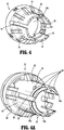
FIG. 5 is a side perspective view from a distal portion of a knife carrier pusher of the distal portion of the stapling device shown inFIG. 3 ; -
FIG. 5A is a side perspective view of a pusher drive member of the distal portion of the stapling device shown inFIG. 3 ; -
FIG. 6 is a cross-sectional view taken along section line 6-6 ofFIG. 2 illustrating the distal portion of the surgical stapling device in a pre-fired state; -
FIG. 6A is an enlarged view of the indicated area of detail shown inFIG. 6 ; -
FIG. 6B is a side cross-sectional view of the distal portion of the surgical stapling device shown inFIG. 6 in a post-fired state with the knife carrier and knife carrier pusher in a retracted position; -
FIG. 7 is a side cross-sectional view of the distal portion of the surgical stapling device shown inFIG. 6A in a post-fired state with the knife carrier and knife carrier pusher in an advanced position; and -
FIG. 8 is a side cross-sectional view of the distal portion of the surgical stapling device shown inFIG. 7 in a post-fired state with the knife carrier and the drive member in retracted positions, and the knife carrier pusher moving towards its retracted position to facilitate separation of the knife carrier and the knife carrier pusher. - The presently disclosed circular stapling device will now be described in detail with reference to the drawings in which like reference numerals designate identical or corresponding elements in each of the several views. In this description, the term "proximal" is used generally to refer to that portion of the stapling device that is closer to a clinician, while the term "distal" is used generally to refer to that portion of the stapling device that is farther from the clinician.
- The presently disclosed circular stapling device includes a shell or reload assembly that is supported on a distal portion of an elongate shaft of the stapling device. The reload assembly includes a housing, a staple cartridge that supports a plurality of annular rows of staples, a staple pusher assembly, a knife carrier, and an annular knife supported on the knife carrier. The pusher assembly includes an inner surface defining a through bore. The inner surface of the pusher assembly has a proximal portion that defines a counter bore. The knife carrier is movably positioned within the through bore of the pusher assembly.
- The elongate body includes a pusher drive member and a knife carrier pusher. The pusher drive member has an inner surface that defines a through bore that is aligned with the through bore of the pusher assembly. A distal portion of the inner surface of the pusher drive member is tapered outwardly in a distal direction. The knife carrier is movably positioned within the pusher assembly and pusher drive member and includes a plurality of proximally extending resilient legs that are movable from a first position engaged with the knife carrier pusher to couple the knife carrier with the knife carrier pusher to a second position disengaged from the knife carrier pusher. Each of the resilient legs supports an outwardly extending detent that is positioned within the counter bore of the pusher assembly when the stapling device is in a pre-fired state. When the stapling device is actuated to fire staples, the pusher drive member is advanced to advance the pusher assembly to eject staples from the staple cartridge. Thereafter, the knife carrier pusher is advanced to advance the knife carrier and the knife to cut or core tissue. After tissue is stapled and cored, the pusher drive member is retracted, and the knife carrier pusher is subsequently retracted to retract the knife carrier and the knife into the housing. As the knife carrier is retracted, the detents on the resilient legs of the knife carrier are moved from a position within the counter bore of the pusher assembly into contact with the tapered distal portion of the pusher drive member to urge the resilient legs of the knife carrier to the second position to uncouple the knife carrier pusher from the knife carrier. The presently disclosed reload assembly minimizes the likelihood of premature disengagement of the knife carrier from the knife carrier pusher while reducing the force required to effect uncoupling of the knife carrier from the knife carrier pusher after the knife has been fully retracted into the housing.
-
FIGS. 1 and2 illustrate an exemplary embodiment of the presently disclosedsurgical stapling device 10. Thesurgical stapling device 10 includes ahandle assembly 12, an elongate body oradaptor assembly 14, a reloadassembly 16, and ananvil assembly 18 supported for movement in relation to the reloadassembly 16 between spaced and approximated positions as is known in the art. The reloadassembly 16 includes aproximal portion 16a that is releasably coupled to adistal portion 14a of theelongate body 14. Thehandle assembly 12 includes astationary grip 22, andactuation buttons 24 for controlling operation of the various functions of thesurgical stapling device 10 including approximation of the reload andanvil assemblies staples 36 from the reload 16, and cutting or coring of tissue. Although thesurgical stapling device 10 is illustrated as an electrically powered stapling device including an electricallypowered handle assembly 12 and anelongate body 14 in the form of an adaptor assembly that translates power from thehandle assembly 12 to the reload andanvil assemblies U.S. Patent Nos. 9,023,014 9,055,943 surgical stapling device 10 can be configured for use with a robotic system and need not include a handle assembly. - Referring to
FIGS. 2-3 , the reloadassembly 16 includes ahousing 26, apusher assembly 28, aknife carrier 30, anannular knife 32 supported on theknife carrier 30, astaple cartridge 34, andstaples 36 supported within thestaple cartridge 34. Thestaple cartridge 34 is annular and defines annular rows of staple pockets 40 (FIG. 3 ). Each of the staple pockets 40 supports one of thestaples 36. Thepusher assembly 28 includes anannular pusher 42 and astaple pushing member 44 that together define a longitudinal throughbore 28a. Thepusher 42 has a distal portion that abuts a proximal portion of thestaple pushing member 44 such that distal movement of thepusher 42 within thehousing 26 effects distal movement of thestaple pushing member 44 within thehousing 26. Thestaple pushing member 44 of the reload 16 has a plurality offingers 46. Each of the plurality offingers 46 is received within a respective one of the staple pockets 40 of thestaple cartridge 34 and is movable through the respectivestaple pocket 40 to eject the staple 36 from thestaple pocket 40 when thestaple pushing member 44 is moved distally within thehousing 26 from a retracted position to an advanced position. - Referring also to
FIG. 4 , thepusher 42 of thepusher assembly 28 includes aninner surface 42a that defines a portion of the longitudinal throughbore 28a. Theinner surface 42a of thepusher 42 is stepped outwardly at its proximal portion to further define counter bore 43 which is discussed in further detail below. - Referring again to
FIG. 3 , theanvil assembly 18 includes ananvil shaft 18a that is releasably coupled to an approximation mechanism (not shown) of thesurgical stapling device 10 as is known in the art. Theanvil shaft 18a is movable within a through bore 41 (FIG. 6 ) defined by aninner housing portion 26a of thehousing 26 as theanvil assembly 18 moves between the spaced and approximated positions in relation to thestaple cartridge 34. - Referring to
FIGS. 3 and4A , theknife carrier 30 is movably supported within the throughbore 28a of thepusher assembly 28 between retracted and advanced positions. In the advanced position of the knife carrier 30 (FIG. 7 ), theknife 30 extends from a distal end of thestaple cartridge 32 and in the retracted position of the knife carrier 30 (FIG. 6 ), theknife 32 is recessed within thestaple cartridge 34 to shield theknife 32 from contact by a clinician. Theknife carrier 30 includes a substantially cylindricaldistal portion 50 and a substantially cylindrical smaller diameterproximal portion 52. The smaller diameterproximal portion 52 is defined by a plurality of spacedresilient legs 53 that defineslots 54 there between. Theslots 54 receive projections (not shown) defined within thepusher 42 to guide movement of theknife carrier 30 from the retracted position to the advanced position within thepusher assembly 28. Thelongitudinal slots 54 also facilitate inward flexing of theresilient legs 53 of theknife carrier 30 from a first position in which theresilient legs 53 are engaged with a knife carrier pusher 70 (FIG 5 ) (described in detail below) and a second position in which theknife carrier 30 is disengaged from the knife carrier pusher 70 (FIG. 8 ) as discussed in further detail below. In embodiments, theknife 32 is secured about thedistal portion 50 of theknife carrier 30 such as by crimping. Alternately, other fastening techniques can be used to secure theknife 32 to theknife carrier 30. Adistal-most portion 50a of thedistal portion 50 of theknife carrier 30 can be recessed to receive theannular knife 32 such that theknife 32 and theknife carrier 30 define a smooth external surface. - Each of the
resilient legs 53 of theknife carrier 30 supports an outwardly extendingdetent 55. Thedetents 55 can be integrally formed with therespective legs 53 or, alternatively, can be formed as aseparate plug 55a (FIG. 6B ) that is inserted into anopening 57 formed in a respectiveresilient leg 53. Thedetents 55 are positioned within the counter bore 43 (FIG. 6 ) of thepusher assembly 28 when thesurgical stapling device 10 is in a pre-fired state with theknife carrier 30 and thepusher assembly 28 in retracted positions. Referring also toFIG. 4A , each of theresilient legs 53 of theknife carrier 30 defines a longitudinal axis and includesfirst engagement structure 60 that is configured to engage a distal portion of theknife carrier pusher 70 of theelongate body 14 as described in detail below to releasably couple theknife carrier 30 to the knife carrier pusher 70 (FIG. 5 ). In embodiments, thefirst engagement structure 60 includes an annular channel orrecess 60a that is configured to receive second engagement structure 80 (FIG. 5 ) formed on a distal portion of theknife carrier pusher 70 as described in further detail below. Although shown as annular, other recess configurations are envisioned. Theannular channel 60a of thefirst engagement structure 60 is defined by distal and proximal walls, wherein theproximal wall 80a is substantially orthogonal in relation to the longitudinal axis of theknife carrier 30. In embodiments, aproximal portion 53a of eachresilient leg 53 of theknife carrier 30 is tapered inwardly towards the longitudinal axis of theknife carrier 30 in a proximal direction. The taperedproximal portion 53a and thelongitudinal slots 54 of theknife carrier 30 facilitate attachment of theknife carrier 30 to the distal portion of theknife carrier pusher 70 as the reloadassembly 16 is being attached to theelongate body 14 as described in detail below. - Referring also to
FIG. 5 , theknife carrier pusher 70 includes a substantiallycylindrical body 74 having acutout 75 that extends from a central portion of thebody 74 to the distal portion of thebody 74. Theknife carrier pusher 70 is tubular and includes aninner wall 81 defining a throughbore 74a. In embodiments, thesecond engagement structure 80 includes aprotrusion 81a formed on a distal portion of theinner wall 81 of theknife carrier pusher 70. Although theprotrusion 81a is shown as being annular, other configurations are envisioned. Theannular protrusion 81a includes aproximal surface 81b that is substantially orthogonal to a longitudinal axis of theknife carrier pusher 70. Theannular protrusion 81a is received within theannular channel 60a (FIG. 4A ) of theknife carrier 30 when theresilient legs 53 are in the first position (FIG. 6 ) to couple theknife carrier 30 to theknife carrier pusher 70. Theproximal wall 81b of theannular protrusion 81a is positioned to engage theproximal wall 80a (FIG. 6A ) defining theannular channel 60a such that retraction of theknife carrier pusher 70 effects retraction of theknife carrier 30. In embodiments, thecylindrical body 74 of theknife carrier pusher 70 definesrecesses 84 that are configured to engage a drive member (not shown) supported within theelongate body 14. The drive member is secured to the proximal portion of theknife carrier pusher 70 and is operable to advance and retract theknife carrier pusher 70 within thehousing 26 of the reloadassembly 16 as known in the art.U.S. Publication No. 2016/0106406 ("the '406 Publication") which was filed on October 6, 2015 discloses such an elongate body or adaptor and is incorporated herein in its entirety by reference. - Referring to
FIGS. 3 and5A , theelongate body 14 includes apusher drive member 90 defining a longitudinal axis and having atubular body 90a having aninner surface 92 defining a throughbore 92a. A distal portion of theinner surface 92 defines aleading edge 94 that is tapered outwardly in a distal direction. The throughbore 92a receives theknife carrier 30 and theknife carrier pusher 70 as theknife carrier 30 and theknife carrier pusher 70 are moved between retracted and advanced positions as described in further detail below. Thetubular body 90a includes a proximal portion that is configured to engage structure within theelongate body 14 to effect translation of thepusher drive member 90 between the advanced and retracted positions. The '406 Publication which is incorporated herein in its entirety by reference discloses an elongate body including such structure. -
FIGS. 6 and 6A illustrate a distal portion of the staplingdevice 10 in a pre-fired state. In the pre-fired state, thepusher assembly 28 and theknife carrier 30 of the reload 16 and theknife carrier pusher 70 and thepusher drive member 90 of theelongate body 14 are in retracted positions. In their retracted positions, thepusher assembly 28 and thepusher drive member 90 extend about aninterface 106 between thefirst engagement structure 60 on the proximal portion of theresilient legs 53 of theknife carrier 30 and thesecond engagement structure 80 positioned on the distal portion theknife carrier pusher 70. In addition, theresilient legs 53 of theknife carrier 30 are in their first position with thedetents 55 received within the counter bore 43 of thepusher 42 of thepusher assembly 28, and theknife carrier 30 and theknife carrier pusher 70 are in an engaged state. -
FIG. 6B illustrates the distal portion of thesurgical stapling device 10 in a post-fired state with thepusher assembly 28 and thepusher drive member 90 moved in the direction indicated by arrows "A" to their advanced positions to eject the staples 36 (FIG. 6 ) from thestaple cartridge 34. In addition, theknife carrier 30, theknife 32, and theknife carrier pusher 70 remain in their retracted positions. In this state, thedetents 55 are positioned in a proximal portion of the counter bore 43 such that theresilient legs 53 of theknife carrier 30 remain in their first position and theknife carrier 30 remains in engagement with theknife carrier pusher 70. -
FIG. 7 illustrates the distal portion of thesurgical stapling device 10 in a post-fired state after theknife carrier pusher 70 and theknife 32 have been moved to their advanced positions in the direction indicated by arrows "B". In this state, thepusher assembly 28,pusher drive member 90,knife carrier 30 andknife carrier pusher 70 are in their advanced positions with thedetents 55 in a central portion of the counter bore 43. As such, theresilient legs 53 of theknife carrier 30 remain in their first position with the first andsecond engagement structures knife carrier 30 and theknife carrier pusher 70 in engagement such that theknife carrier 30 remains coupled to theknife carrier pusher 70. - Referring to
FIG. 8 , after the staples 36 (FIG. 3 ) have been fired and tissue has been cut, thepusher drive member 90 is retracted. As discussed above, thepusher drive member 90 is in abutting relation with thepusher assembly 28 and thus, thepusher assembly 28 does not retract with thepusher drive member 90. Subsequently (or simultaneously), theknife carrier pusher 70 is moved to a fully retracted position to retract theknife carrier 30 within thepusher assembly 28 and thepusher drive member 90. As theknife carrier pusher 70 is moved to the fully retracted position, theproximal wall 81b of theannular protrusion 81a of thesecond engagement structure 80 engages theproximal wall 80a defining theannular channel 60a such that retraction of theknife carrier pusher 70 effects retraction of theknife carrier 30. Because thewalls knife carrier 30 as discussed above, the force applied by thewall 81b onto thewall 80a does not urge theresilient legs 53 towards their second position. - As the
knife carrier 30 is moved towards its retracted position, thedetents 55 move through the counter bore 43 such that theresilient legs 53 remain in their first position engaged with theknife carrier pusher 70 to retract theknife 32 into thehousing 26 of the reloadassembly 16. After theknife 32 is retracted into thehousing 26, thedetents 55 are positioned to engage the tapered leadingedge 94 of thepusher drive member 90. When thedetents 55 engage the tapered leadingedge 94 of thepusher drive member 90, theresilient legs 53 are urged inwardly in the direction indicated by arrows "C" from their first position towards their second position to disengage thefirst engagement structure 60 from thesecond engagement structure 80 and uncouple theknife carrier 30 from theknife carrier pusher 70. By providingdetents 55, the present reloadassembly 16 does not rely on a back angle on theknife carrier pusher 70 to effect uncoupling of theknife carrier 30 from theknife carrier pusher 70. Thedetents 55 function to accurately control the timing of separation between theknife carrier 30 and theknife carrier pusher 70 and minimize the likelihood of premature separation of theknife carrier 30 from theknife carrier pusher 70 while minimizing the force required to effect separation of theknife carrier 30 and theknife carrier pusher 70. - As discussed above, the
proximal portion 53a of eachresilient leg 53 of theknife carrier 30 is tapered inwardly towards the longitudinal axis of theknife carrier 30 in a proximal direction. Referring again toFIG. 6A , when the reloadassembly 16 is attached to the distal portion of theelongate body 14 of thesurgical stapling device 10, the taperedproximal portion 53a of theresilient legs 53 will engage adistal face 100 of theknife carrier pusher 70. Engagement between the taperedproximal portion 53a of theresilient legs 53 and thedistal face 100 of theknife carrier pusher 70 will cam theresilient legs 53 downwardly to allow thefirst engagement structure 60 to pass by thesecond engagement structure 80. Due to the resilient nature of thelegs 53, thesecond engagement structure 80 will snap into thefirst engagement structure 60 when the structures are aligned to couple theknife carrier 30 and theknife carrier pusher 70. - Persons skilled in the art will understand that the devices and methods specifically described herein and illustrated in the accompanying drawings are non-limiting exemplary embodiments. It is envisioned that the elements and features illustrated or described in connection with one exemplary embodiment may be combined with the elements and features of another without departing from the scope of the present disclosure. For example, any of the embodiments disclosed herein could include staples with different sizes and/or surfaces with different heights on the staple cartridge and/or anvil. Any of the embodiments disclosed herein can include a surgical buttress that may or may not be used to deliver a therapeutic substance such as a drug or brachytherapy seed. As well, one skilled in the art will appreciate further features and advantages of the disclosure based on the above-described embodiments. Accordingly, the disclosure is not to be limited by what has been particularly shown and described, except as indicated by the appended claims.
- The invention may be described by reference to the following numbered paragraphs:-
- 1. A surgical stapling device comprising:
- an elongate body defining a longitudinal axis and having a proximal portion and a distal portion, the elongate body including a pusher drive member and a knife carrier pusher, the pusher drive member having an inner surface defining a through bore having a tapered distal portion;
- a reload assembly including a housing , a staple cartridge supporting a plurality of staples, a pusher assembly, a knife carrier, and a knife, the pusher assembly movably supported within the housing between a retracted position and an advanced position to eject the plurality of staples from the staple cartridge, the pusher assembly having an inner surface defining a through bore, the inner surface having a proximal portion defining a counter bore, wherein the knife carrier supports a knife and includes first engagement structure, the knife carrier having at least one detent; and
- the knife carrier pusher including second engagement structure configured to releasably engage the first engagement structure of the knife carrier to couple the knife carrier pusher to the knife carrier, the first engagement structure being movable from a first position engaged with the second engagement structure to a second position disengaged from the second engagement structure;
- wherein when the surgical stapling device is in a pre-fired state, the at least one detent is positioned within the counter bore of the pusher assembly, and when the knife carrier is retracted after the surgical stapling device has been actuated to eject the plurality of staples and to dissect tissue, the detents are positioned to engage the tapered distal portion of the pusher drive member to urge the first engagement from the first position towards the second position to uncouple the knife carrier from the knife carrier pusher.
- 2. The surgical stapling device of paragraph 1, wherein the knife carrier includes a proximal portion defined by a plurality of flexible legs.
- 3. The surgical stapling device of
paragraph 2, wherein the at least one detent includes a detent supported on each of the plurality of flexible legs. - 4. The surgical stapling device of paragraph 3, wherein each of the detents extends outwardly from a longitudinal axis of the knife carrier.
- 5. The surgical stapling device of paragraph 1, wherein the knife carrier is movably positioned within the through bore defined by the pusher assembly.
- 6. The surgical stapling device of paragraph 3, wherein each of the detents is integrally formed with a respective one of the plurality of flexible legs.
- 7. The surgical stapling device of
paragraph 6, wherein the first engagement structure is formed on a proximal portion of the plurality of flexible legs. - 8. The surgical stapling device of paragraph 7, wherein the first engagement structure includes a recess formed on the proximal portion of the plurality of flexible legs.
- 9. The surgical stapling device of paragraph 8, wherein the recess includes an annular channel.
- 10. The surgical stapling device of paragraph 8, wherein the proximal portion of each of the plurality of flexible legs is tapered towards a longitudinal axis of the knife carrier in the proximal direction.
- 11. The surgical stapling device of paragraph 8, wherein the second engagement structure includes a protrusion configured to be received within the recess of the first engagement structure.
- 12. The surgical stapling device of
paragraph 10, wherein the protrusion is annular. - 13. The surgical stapling device of paragraph 11, wherein the recess of the first engagement structure is defined by a proximal wall that is orthogonal in relation to the longitudinal axis of the knife carrier.
- 14. The surgical stapling device of paragraph 13, wherein the protrusion of the second engagement structure is defined by a proximal wall which is orthogonal in relation to the longitudinal axis of the knife carrier pusher.
- 15. The surgical stapling device of paragraph 13, wherein the proximal wall of the second engagement structure is positioned to engage the proximal wall of the first engagement structure to translate proximal movement of the knife carrier pusher into proximal movement of the knife carrier.
- 16. The surgical stapling device of paragraph 1, wherein the handle assembly is an electrically powered handle assembly.
- 17. The surgical stapling device of paragraph 1, wherein the reload assembly is releasably coupled to the elongate body.
- 18. The surgical stapling device of paragraph 1, wherein the pusher assembly includes an annular pusher and a staple pushing member.
- 19. The surgical stapling device of paragraph 17, wherein the annular pusher is positioned to abut a proximal portion of the staple pushing member.
Claims (14)
- A surgical stapling device comprising:an elongate body defining a longitudinal axis and having a proximal portion and a distal portion, the elongate body including a pusher drive member and a knife carrier pusher, the pusher drive member having an inner surface defining a through bore having a tapered distal portion;a reload assembly including a housing , a staple cartridge supporting a plurality of staples, a pusher assembly, a knife carrier, and a knife, the pusher assembly movably supported within the housing between a retracted position and an advanced position to eject the plurality of staples from the staple cartridge, the pusher assembly having an inner surface defining a through bore, the inner surface having a proximal portion defining a counter bore, wherein the knife carrier supports a knife and includes first engagement structure, the knife carrier having at least one detent; and
the knife carrier pusher including second engagement structure configured to releasably engage the first engagement structure of the knife carrier to couple the knife carrier pusher to the knife carrier, the first engagement structure being movable from a first position engaged with the second engagement structure to a second position disengaged from the second engagement structure;wherein when the surgical stapling device is in a pre-fired state, the at least one detent is positioned within the counter bore of the pusher assembly, and when the knife carrier is retracted after the surgical stapling device has been actuated to eject the plurality of staples and to dissect tissue, the detents are positioned to engage the tapered distal portion of the pusher drive member to urge the first engagement from the first position towards the second position to uncouple the knife carrier from the knife carrier pusher. - The surgical stapling device of claim 1, wherein the knife carrier includes a proximal portion defined by a plurality of flexible legs.
- The surgical stapling device of claim 2, wherein the at least one detent includes a detent supported on each of the plurality of flexible legs; preferably wherein each of the detents extends outwardly from a longitudinal axis of the knife carrier.
- The surgical stapling device of any preceding claim, wherein the knife carrier is movably positioned within the through bore defined by the pusher assembly.
- The surgical stapling device of claim 3, wherein each of the detents is integrally formed with a respective one of the plurality of flexible legs; preferably wherein the first engagement structure is formed on a proximal portion of the plurality of flexible legs.
- The surgical stapling device of claim 5, wherein the first engagement structure includes a recess formed on the proximal portion of the plurality of flexible legs.
- The surgical stapling device of claim 6, wherein the recess includes an annular channel; and/ or wherein the proximal portion of each of the plurality of flexible legs is tapered towards a longitudinal axis of the knife carrier in the proximal direction.
- The surgical stapling device of claim 6 or claim 7, wherein the second engagement structure includes a protrusion configured to be received within the recess of the first engagement structure.
- The surgical stapling device of claim 8, wherein the protrusion is annular.
- The surgical stapling device of claim 7, wherein the recess of the first engagement structure is defined by a proximal wall that is orthogonal in relation to the longitudinal axis of the knife carrier.
- The surgical stapling device of claim 8, wherein the protrusion of the second engagement structure is defined by a proximal wall which is orthogonal in relation to the longitudinal axis of the knife carrier pusher.
- The surgical stapling device of claim 8, wherein the proximal wall of the second engagement structure is positioned to engage the proximal wall of the first engagement structure to translate proximal movement of the knife carrier pusher into proximal movement of the knife carrier.
- The surgical stapling device of any preceding claim, wherein the handle assembly is an electrically powered handle assembly; and/or wherein the reload assembly is releasably coupled to the elongate body.
- The surgical stapling device of any preceding claim, wherein the pusher assembly includes an annular pusher and a staple pushing member; preferably wherein the annular pusher is positioned to abut a proximal portion of the staple pushing member.
Applications Claiming Priority (1)
| Application Number | Priority Date | Filing Date | Title |
|---|---|---|---|
| US15/467,153 US10342534B2 (en) | 2017-03-23 | 2017-03-23 | Surgical stapling device with releasable knife carrier |
Publications (2)
| Publication Number | Publication Date |
|---|---|
| EP3378411A1 true EP3378411A1 (en) | 2018-09-26 |
| EP3378411B1 EP3378411B1 (en) | 2019-11-06 |
Family
ID=61750025
Family Applications (1)
| Application Number | Title | Priority Date | Filing Date |
|---|---|---|---|
| EP18163304.1A Active EP3378411B1 (en) | 2017-03-23 | 2018-03-22 | Surgical stapling device with releasable knife carrier |
Country Status (6)
| Country | Link |
|---|---|
| US (2) | US10342534B2 (en) |
| EP (1) | EP3378411B1 (en) |
| JP (1) | JP7123588B2 (en) |
| AU (1) | AU2018201023A1 (en) |
| CA (1) | CA2994459A1 (en) |
| ES (1) | ES2761610T3 (en) |
Cited By (2)
| Publication number | Priority date | Publication date | Assignee | Title |
|---|---|---|---|---|
| EP3838185A1 (en) * | 2019-12-16 | 2021-06-23 | Covidien LP | Reload assembly with knife carrier lockout |
| EP3975876A4 (en) * | 2019-05-31 | 2023-01-04 | Covidien LP | Circular stapling device |
Families Citing this family (5)
| Publication number | Priority date | Publication date | Assignee | Title |
|---|---|---|---|---|
| US9730694B2 (en) * | 2014-07-01 | 2017-08-15 | Covidien Lp | Loading unit including shipping assembly |
| US10342534B2 (en) | 2017-03-23 | 2019-07-09 | Covidien Lp | Surgical stapling device with releasable knife carrier |
| US10952734B2 (en) | 2018-04-23 | 2021-03-23 | Covidien Lp | Stapling device with cut ring biasing member |
| US11065005B2 (en) * | 2018-11-07 | 2021-07-20 | Covidien Lp | Reload assembly for a circular stapling device |
| US11464510B2 (en) | 2019-07-26 | 2022-10-11 | Covidien Lp | Reload assembly with knife carrier lockout |
Citations (10)
| Publication number | Priority date | Publication date | Assignee | Title |
|---|---|---|---|---|
| US4917114A (en) * | 1986-10-17 | 1990-04-17 | United States Surgical Corporation | Surgical fastener and surgical stapling apparatus |
| US5609285A (en) * | 1992-02-07 | 1997-03-11 | Ethicon, Inc. | Surgical anastomosis stapling instrument with flexible support shaft and anvil adjusting mechanism |
| WO2004112618A2 (en) * | 2003-06-17 | 2004-12-29 | Tyco Healthcare Group, Lp | Surgical stapling device |
| US7364060B2 (en) * | 2003-10-17 | 2008-04-29 | Tyco Healthcare Group Lp | Surgical stapling device with tiltable anvil head |
| US9023014B2 (en) | 2007-09-21 | 2015-05-05 | Covidien Lp | Quick connect assembly for use between surgical handle assembly and surgical accessories |
| US20160007999A1 (en) * | 2014-07-09 | 2016-01-14 | Covidien Lp | Methods and devices for performing a surgical anastomosis |
| US20160106406A1 (en) | 2014-10-21 | 2016-04-21 | Covidien Lp | Adapter, extension, and connector assemblies for surgical devices |
| EP3108828A2 (en) * | 2015-06-26 | 2016-12-28 | Ethicon Endo-Surgery, LLC | Bailout assembly for surgical stapler |
| WO2017172704A2 (en) * | 2016-04-01 | 2017-10-05 | Ethicon Llc | Surgical stapling system comprising a shiftable transmission |
| US20180125495A1 (en) * | 2016-11-04 | 2018-05-10 | Covidien Lp | Stapling device with self-releasing knife carrier pusher |
Family Cites Families (342)
| Publication number | Priority date | Publication date | Assignee | Title |
|---|---|---|---|---|
| CA908529A (en) | 1972-08-29 | V. Astafiev Georgy | Surgical instrument for suturing hollow organs in infants | |
| DE1057729B (en) | 1954-03-29 | 1959-05-21 | Lameris Instr N V | Surgical device for connecting two parts of the intestine |
| GB787043A (en) | 1954-09-15 | 1957-11-27 | Sylvania Electric Prod | Method for production of silicon |
| CA736256A (en) | 1962-08-27 | 1966-06-14 | S. Kasoolin Viacheslav | Instrument for suturing esophagus to intestine or stomach |
| FR1461464A (en) | 1965-08-20 | 1966-02-25 | Niiex Khirurgicheskoi Apparatu | Surgical device for suturing organs |
| CH470170A (en) | 1968-02-02 | 1969-03-31 | Vnii Khirurgicheskoi Apparatur | Device for applying round anastomoses |
| US3638652A (en) | 1970-06-01 | 1972-02-01 | James L Kelley | Surgical instrument for intraluminal anastomosis |
| US3771526A (en) | 1972-02-07 | 1973-11-13 | P Rudie | Anastomosis clamp |
| US4603693A (en) | 1977-05-26 | 1986-08-05 | United States Surgical Corporation | Instrument for circular surgical stapling of hollow body organs and disposable cartridge therefor |
| US4304236A (en) | 1977-05-26 | 1981-12-08 | United States Surgical Corporation | Stapling instrument having an anvil-carrying part of particular geometric shape |
| US4573468A (en) | 1977-05-26 | 1986-03-04 | United States Surgical Corporation | Hollow body organ stapling instrument and disposable cartridge employing relief vents |
| NL7711347A (en) | 1977-10-17 | 1979-04-19 | Carl Robert Erik Daantje | Stapling instrument for joining intestine ends - has head coupling rod in two parts screwing together with hand grip |
| US4207898A (en) | 1978-03-27 | 1980-06-17 | Senco Products, Inc. | Intralumenal anastomosis surgical stapling instrument |
| US4198982A (en) | 1978-03-31 | 1980-04-22 | Memorial Hospital For Cancer And Allied Diseases | Surgical stapling instrument and method |
| DE2947107A1 (en) | 1978-12-07 | 1980-06-26 | United States Surgical Corp | ACCURATELY ALIGNED CARTRIDGE AND INSTRUMENT FOR CLAMPING ANASTOMOSES |
| SU1088712A1 (en) | 1979-11-14 | 1984-04-30 | Всесоюзный научно-исследовательский и испытательный институт медицинской техники | Apparatus for circular suture of blood vessels |
| AU534210B2 (en) | 1980-02-05 | 1984-01-12 | United States Surgical Corporation | Surgical staples |
| US4319576A (en) | 1980-02-26 | 1982-03-16 | Senco Products, Inc. | Intralumenal anastomosis surgical stapling instrument |
| US4289133A (en) | 1980-02-28 | 1981-09-15 | Senco Products, Inc. | Cut-through backup washer for the scalpel of an intraluminal surgical stapling instrument |
| US4606343A (en) | 1980-08-18 | 1986-08-19 | United States Surgical Corporation | Self-powered surgical fastening instrument |
| US4351466A (en) | 1980-10-16 | 1982-09-28 | United States Surgical Corporation | Disposable instrument for surgical fastening |
| US4379457A (en) | 1981-02-17 | 1983-04-12 | United States Surgical Corporation | Indicator for surgical stapler |
| US4476863A (en) | 1981-03-09 | 1984-10-16 | Kanshin Nikolai N | Surgical instrument for establishing circular coloanastomoses |
| US4632290A (en) | 1981-08-17 | 1986-12-30 | United States Surgical Corporation | Surgical stapler apparatus |
| US4576167A (en) | 1981-09-03 | 1986-03-18 | United States Surgical Corporation | Surgical stapler apparatus with curved shaft |
| SU1114405A1 (en) | 1982-02-23 | 1984-09-23 | Всесоюзный научно-исследовательский и испытательный институт медицинской техники | Surgical suturing apparatus for placing compression anastomoses on the organs of digestive tract |
| US4485817A (en) | 1982-05-28 | 1984-12-04 | United States Surgical Corporation | Surgical stapler apparatus with flexible shaft |
| US4473077A (en) | 1982-05-28 | 1984-09-25 | United States Surgical Corporation | Surgical stapler apparatus with flexible shaft |
| US4488523A (en) | 1982-09-24 | 1984-12-18 | United States Surgical Corporation | Flexible, hydraulically actuated device for applying surgical fasteners |
| DE3301713A1 (en) | 1983-01-20 | 1984-07-26 | Horst Dr. 3004 Isernhagen Ziegler | Surgical clip suture apparatus for producing circular joins |
| US4592354A (en) | 1983-10-11 | 1986-06-03 | Senmed, Inc. | Tissue retention spool for intraluminal anastomotic surgical stapling instrument and methods |
| US4505414A (en) | 1983-10-12 | 1985-03-19 | Filipi Charles J | Expandable anvil surgical stapler |
| US4550870A (en) | 1983-10-13 | 1985-11-05 | Alchemia Ltd. Partnership | Stapling device |
| IT1173284B (en) | 1984-02-16 | 1987-06-18 | Riccardo Rosati | CIRCULAR MECHANICAL STAPLING MACHINE |
| US4667673A (en) | 1984-03-12 | 1987-05-26 | American Cyanamid Company | Anastomotic device applicator and method |
| US4671445A (en) | 1984-08-09 | 1987-06-09 | Baxter Travenol Laboratories, Inc. | Flexible surgical stapler assembly |
| US4754909A (en) | 1984-08-09 | 1988-07-05 | Barker John M | Flexible stapler |
| US4665917A (en) | 1985-01-28 | 1987-05-19 | Ethicon, Inc. | Tissue gripper for use with intraluminal stapling device |
| AU582625B2 (en) | 1985-01-28 | 1989-04-06 | Ethicon Inc. | Tissue gripper for use with intraluminal stapling device |
| US4703887A (en) | 1985-01-28 | 1987-11-03 | Ethicon, Inc. | Collapsible purse string aid for use with intraluminal stapling device |
| JPS635697Y2 (en) | 1985-04-04 | 1988-02-17 | ||
| JPS62140776A (en) | 1985-12-16 | 1987-06-24 | 海老原 代師行 | Stapler |
| US4903697A (en) | 1986-03-27 | 1990-02-27 | Semion Resnick | Cartridge assembly for a surgical stapling instrument |
| US4700703A (en) | 1986-03-27 | 1987-10-20 | Semion Resnick | Cartridge assembly for a surgical stapling instrument |
| WO1987006448A1 (en) | 1986-04-21 | 1987-11-05 | Finanzaktiengesellschaft Globe Control | Anastomosis process and device |
| US4752024A (en) | 1986-10-17 | 1988-06-21 | Green David T | Surgical fastener and surgical stapling apparatus |
| US4776506A (en) | 1986-11-13 | 1988-10-11 | United States Surgical Corporation | Surgical stapler apparatus |
| US4873977A (en) | 1987-02-11 | 1989-10-17 | Odis L. Avant | Stapling method and apparatus for vesicle-urethral re-anastomosis following retropubic prostatectomy and other tubular anastomosis |
| US5119983A (en) | 1987-05-26 | 1992-06-09 | United States Surgical Corporation | Surgical stapler apparatus |
| US5158222A (en) | 1987-05-26 | 1992-10-27 | United States Surgical Corp. | Surgical stapler apparatus |
| US5285944A (en) | 1987-05-26 | 1994-02-15 | United States Surgical Corporation | Surgical stapler apparatus |
| SU1616624A1 (en) | 1987-07-14 | 1990-12-30 | Предприятие П/Я А-3697 | Surgical suturing apparatus |
| SU1509052A1 (en) | 1988-01-18 | 1989-09-23 | С. А. Попов | Surgical suturing apparatus |
| US4907591A (en) | 1988-03-29 | 1990-03-13 | Pfizer Hospital Products Group, Inc. | Surgical instrument for establishing compression anastomosis |
| US5193731A (en) | 1988-07-01 | 1993-03-16 | United States Surgical Corporation | Anastomosis surgical stapling instrument |
| US5005749A (en) | 1988-07-01 | 1991-04-09 | United States Surgical Corp. | Anastomosis surgical stapling instrument |
| ES2011110A6 (en) | 1988-09-02 | 1989-12-16 | Lopez Hervas Pedro | Hydraulic device with flexible body for surgical anastomosts |
| US5197648A (en) | 1988-11-29 | 1993-03-30 | Gingold Bruce S | Surgical stapling apparatus |
| WO1990006085A1 (en) | 1988-11-29 | 1990-06-14 | Gingold Bruce S | Surgical stapling apparatus |
| US4893662A (en) | 1988-12-06 | 1990-01-16 | Vito Gervasi | Cutting tool |
| CH677728A5 (en) | 1989-10-17 | 1991-06-28 | Bieffe Medital Sa | |
| US5403333A (en) | 1990-08-28 | 1995-04-04 | Robert L. Kaster | Side-to-end vascular anastomotic staple apparatus |
| US5047039A (en) | 1990-09-14 | 1991-09-10 | Odis Lynn Avant | Method and apparatus for effecting dorsal vein ligation and tubular anastomosis and laparoscopic prostatectomy |
| US5253793A (en) | 1990-09-17 | 1993-10-19 | United States Surgical Corporation | Apparatus for applying two-part surgical fasteners |
| US5104025A (en) | 1990-09-28 | 1992-04-14 | Ethicon, Inc. | Intraluminal anastomotic surgical stapler with detached anvil |
| US5042707A (en) | 1990-10-16 | 1991-08-27 | Taheri Syde A | Intravascular stapler, and method of operating same |
| CA2055943C (en) | 1990-12-06 | 2003-09-23 | Daniel P. Rodak | Surgical fastening apparatus with locking mechanism |
| US5122156A (en) | 1990-12-14 | 1992-06-16 | United States Surgical Corporation | Apparatus for securement and attachment of body organs |
| US5222963A (en) | 1991-01-17 | 1993-06-29 | Ethicon, Inc. | Pull-through circular anastomosic intraluminal stapler with absorbable fastener means |
| ATE135182T1 (en) | 1991-03-29 | 1996-03-15 | Perouse Implant Lab | SURGICAL STAPLE SEWING DEVICE |
| US5221036A (en) | 1991-06-11 | 1993-06-22 | Haruo Takase | Surgical stapler |
| US5350104A (en) | 1991-08-23 | 1994-09-27 | Ethicon, Inc. | Sealing means for endoscopic surgical anastomosis stapling instrument |
| US5333773A (en) | 1991-08-23 | 1994-08-02 | Ethicon, Inc. | Sealing means for endoscopic surgical anastomosis stapling instrument |
| GR920100358A (en) | 1991-08-23 | 1993-06-07 | Ethicon Inc | Surgical anastomosis stapling instrument. |
| US5474223A (en) | 1991-10-18 | 1995-12-12 | United States Surgical Corporation | Surgical fastener applying apparatus |
| US5443198A (en) | 1991-10-18 | 1995-08-22 | United States Surgical Corporation | Surgical fastener applying apparatus |
| US5197649A (en) | 1991-10-29 | 1993-03-30 | The Trustees Of Columbia University In The City Of New York | Gastrointestinal endoscoptic stapler |
| US5433721A (en) | 1992-01-17 | 1995-07-18 | Ethicon, Inc. | Endoscopic instrument having a torsionally stiff drive shaft for applying fasteners to tissue |
| US5188638A (en) | 1992-02-06 | 1993-02-23 | Tzakis Andreas G | Apparatus and method for preforming anastomosis fastener securement of hollow organs |
| US5348259A (en) | 1992-02-10 | 1994-09-20 | Massachusetts Institute Of Technology | Flexible, articulable column |
| US5425738A (en) | 1992-04-08 | 1995-06-20 | American Cyanamid Company | Endoscopic anastomosis ring insertion device and method of use thereof |
| US5282810A (en) | 1992-04-08 | 1994-02-01 | American Cyanamid Company | Surgical anastomosis device |
| US5355897A (en) | 1992-04-16 | 1994-10-18 | Ethicon, Inc. | Method of performing a pyloroplasty/pylorectomy using a stapler having a shield |
| US5344059A (en) | 1992-05-19 | 1994-09-06 | United States Surgical Corporation | Surgical apparatus and anvil delivery system therefor |
| US5314435A (en) | 1992-05-19 | 1994-05-24 | United States Surgical Corporation | Anvil delivery system |
| JPH0647050A (en) | 1992-06-04 | 1994-02-22 | Olympus Optical Co Ltd | Tissue suture and ligature device |
| US5658300A (en) | 1992-06-04 | 1997-08-19 | Olympus Optical Co., Ltd. | Tissue fixing surgical instrument, tissue-fixing device, and method of fixing tissues |
| US5360154A (en) | 1992-07-17 | 1994-11-01 | United States Surgical Corporation | Apparatus for creating partial anastomoses |
| US5330486A (en) | 1992-07-29 | 1994-07-19 | Wilk Peter J | Laparoscopic or endoscopic anastomosis technique and associated instruments |
| US5261920A (en) | 1992-08-21 | 1993-11-16 | Ethicon, Inc. | Anvil bushing for circular stapler |
| US5368215A (en) | 1992-09-08 | 1994-11-29 | United States Surgical Corporation | Surgical apparatus and detachable anvil rod therefor |
| US5309927A (en) | 1992-10-22 | 1994-05-10 | Ethicon, Inc. | Circular stapler tissue retention spring method |
| US5314436A (en) | 1992-10-30 | 1994-05-24 | Wilk Peter J | Method and apparatus for performing end-to-end anastomoses |
| US5404870A (en) | 1993-05-28 | 1995-04-11 | Ethicon, Inc. | Method of using a transanal inserter |
| US5503320A (en) | 1993-08-19 | 1996-04-02 | United States Surgical Corporation | Surgical apparatus with indicator |
| US5522534A (en) | 1993-10-01 | 1996-06-04 | United States Surgical Corporation | Anvil for surgical stapler |
| US5447514A (en) | 1993-10-01 | 1995-09-05 | United States Surgical Corporation | Circular anastomosis device |
| US5437684A (en) | 1993-10-01 | 1995-08-01 | United States Surgical Corporation | Circular anastomosis device |
| US5454825A (en) | 1993-10-01 | 1995-10-03 | United States Surgical Corporation | Circular anastomosis device with seal |
| CA2132917C (en) | 1993-10-07 | 2004-12-14 | John Charles Robertson | Circular anastomosis device |
| US5503635A (en) | 1993-11-12 | 1996-04-02 | United States Surgical Corporation | Apparatus and method for performing compressional anastomoses |
| DE4407668A1 (en) | 1994-03-09 | 1995-09-14 | Ferdinand Dr Koeckerling | Surgical anastomotic ring setting device |
| US5464415A (en) | 1994-03-15 | 1995-11-07 | Chen; Te-Chuan | Sutureless intestinal anastomosis gun |
| US5860581A (en) | 1994-03-24 | 1999-01-19 | United States Surgical Corporation | Anvil for circular stapler |
| US5715987A (en) | 1994-04-05 | 1998-02-10 | Tracor Incorporated | Constant width, adjustable grip, staple apparatus and method |
| CA2147800C (en) | 1994-05-26 | 2006-07-11 | John Charles Robertson | Circular anastomosis device |
| US5881943A (en) | 1994-06-17 | 1999-03-16 | Heartport, Inc. | Surgical anastomosis apparatus and method thereof |
| CA2192819A1 (en) | 1994-06-17 | 1995-12-28 | Christopher Francis Heck | Surgical stapling instrument and method thereof |
| US5732872A (en) | 1994-06-17 | 1998-03-31 | Heartport, Inc. | Surgical stapling instrument |
| CA2146508C (en) | 1994-08-25 | 2006-11-14 | Robert H. Schnut | Anvil for circular stapler |
| US5685474A (en) | 1994-10-04 | 1997-11-11 | United States Surgical Corporation | Tactile indicator for surgical instrument |
| US5868760A (en) | 1994-12-07 | 1999-02-09 | Mcguckin, Jr.; James F. | Method and apparatus for endolumenally resectioning tissue |
| US7235089B1 (en) | 1994-12-07 | 2007-06-26 | Boston Scientific Corporation | Surgical apparatus and method |
| US5720755A (en) | 1995-01-18 | 1998-02-24 | Dakov; Pepi | Tubular suturing device and methods of use |
| US5904697A (en) | 1995-02-24 | 1999-05-18 | Heartport, Inc. | Devices and methods for performing a vascular anastomosis |
| DE19509115C2 (en) | 1995-03-16 | 1997-11-27 | Deutsche Forsch Luft Raumfahrt | Surgical device for preparing an anastomosis using minimally invasive surgical techniques |
| US5769841A (en) | 1995-06-13 | 1998-06-23 | Electroscope, Inc. | Electrosurgical apparatus for laparoscopic and like procedures |
| US5641111A (en) | 1995-06-28 | 1997-06-24 | Ethicon Endo-Surgery, Inc. | Surgical stapling instrument with anvil cutting guide |
| US5749896A (en) | 1995-07-18 | 1998-05-12 | Cook; Melvin S. | Staple overlap |
| US5839639A (en) | 1995-08-17 | 1998-11-24 | Lasersurge, Inc. | Collapsible anvil assembly and applicator instrument |
| US5814055A (en) | 1995-09-19 | 1998-09-29 | Ethicon Endo-Surgery, Inc. | Surgical clamping mechanism |
| JP3207436B2 (en) | 1995-10-31 | 2001-09-10 | オチコン アクツイエセルスカプ | Anastomotic device for use in performing an end-to-side anastomosis |
| US5836503A (en) | 1996-04-22 | 1998-11-17 | United States Surgical Corporation | Insertion device for surgical apparatus |
| US6050472A (en) | 1996-04-26 | 2000-04-18 | Olympus Optical Co., Ltd. | Surgical anastomosis stapler |
| US6119913A (en) | 1996-06-14 | 2000-09-19 | Boston Scientific Corporation | Endoscopic stapler |
| US6440146B2 (en) | 1996-07-23 | 2002-08-27 | United States Surgical Corporation | Anastomosis instrument and method |
| WO2001052748A2 (en) | 2000-01-18 | 2001-07-26 | Tyco Healthcare Group Lp | Anastomosis instrument and method for performing same |
| US20020019642A1 (en) | 1996-07-23 | 2002-02-14 | Keith Milliman | Anastomosis instrument and method for performing same |
| US6024748A (en) | 1996-07-23 | 2000-02-15 | United States Surgical Corporation | Singleshot anastomosis instrument with detachable loading unit and method |
| US5833698A (en) | 1996-07-23 | 1998-11-10 | United States Surgical Corporation | Anastomosis instrument and method |
| US5855312A (en) | 1996-07-25 | 1999-01-05 | Toledano; Haviv | Flexible annular stapler for closed surgery of hollow organs |
| US5853395A (en) | 1997-02-18 | 1998-12-29 | Dexterity, Inc. | Extracorporeal pneumoperitoneum enclosure and method of use |
| US6338737B1 (en) | 1997-07-17 | 2002-01-15 | Haviv Toledano | Flexible annular stapler for closed surgery of hollow organs |
| US5865361A (en) | 1997-09-23 | 1999-02-02 | United States Surgical Corporation | Surgical stapling apparatus |
| US6117148A (en) | 1997-10-17 | 2000-09-12 | Ravo; Biagio | Intraluminal anastomotic device |
| US5951576A (en) | 1998-03-02 | 1999-09-14 | Wakabayashi; Akio | End-to-side vascular anastomosing stapling device |
| US6279809B1 (en) | 1998-03-10 | 2001-08-28 | Enrico Nicolo | Circular stapler for side to end, side to side and end to side anastomosis |
| US6517566B1 (en) | 1998-05-11 | 2003-02-11 | Surgical Connections, Inc. | Devices and methods for treating e.g. urinary stress incontinence |
| KR20010052335A (en) | 1998-05-11 | 2001-06-25 | 클레어 티. 호브랜드 | Devices and methods for treating e.g. urinary stress incontinence |
| US6478210B2 (en) | 2000-10-25 | 2002-11-12 | Scimed Life Systems, Inc. | Method and device for full thickness resectioning of an organ |
| US6585144B2 (en) | 1998-06-19 | 2003-07-01 | Acimed Life Systems, Inc. | Integrated surgical staple retainer for a full thickness resectioning device |
| US6601749B2 (en) | 1998-06-19 | 2003-08-05 | Scimed Life Systems, Inc. | Multi fire full thickness resectioning device |
| US6126058A (en) | 1998-06-19 | 2000-10-03 | Scimed Life Systems, Inc. | Method and device for full thickness resectioning of an organ |
| US6629630B2 (en) | 1998-06-19 | 2003-10-07 | Scimed Life Systems, Inc. | Non-circular resection device and endoscope |
| DE19836950B4 (en) | 1998-08-17 | 2004-09-02 | Deutsches Zentrum für Luft- und Raumfahrt e.V. | Surgical instrument in the form of a suturing device |
| DE19837258A1 (en) | 1998-08-17 | 2000-03-02 | Deutsch Zentr Luft & Raumfahrt | Device for operating a surgical instrument for anastomosis of hollow organs |
| US6203553B1 (en) | 1999-09-08 | 2001-03-20 | United States Surgical | Stapling apparatus and method for heart valve replacement |
| US6083241A (en) | 1998-11-23 | 2000-07-04 | Ethicon Endo-Surgery, Inc. | Method of use of a circular stapler for hemorrhoidal procedure |
| US6142933A (en) | 1998-11-23 | 2000-11-07 | Ethicon Endo-Surgery, Inc. | Anoscope for hemorrhoidal surgery |
| US6102271A (en) | 1998-11-23 | 2000-08-15 | Ethicon Endo-Surgery, Inc. | Circular stapler for hemorrhoidal surgery |
| US6551334B2 (en) | 1999-04-16 | 2003-04-22 | Integrated Vascular Interventional Technologies, Lc | Externally directed anastomosis systems and externally positioned anastomosis fenestra cutting apparatus |
| US6652542B2 (en) | 1999-04-16 | 2003-11-25 | Integrated Vascular Interventional Technologies, L.C. (Ivit, Lc) | External anastomosis operators and related systems for anastomosis |
| US6743244B2 (en) | 1999-04-16 | 2004-06-01 | Integrated Vascular Interventional Technologies, L.C. | Soft anvil apparatus for cutting anastomosis fenestra |
| US6626921B2 (en) | 1999-04-16 | 2003-09-30 | Integrated Vascular Interventional Technologies, L.C. | Externally positioned anvil apparatus for cutting anastomosis |
| US6402008B1 (en) | 1999-04-19 | 2002-06-11 | Deborah A. Lucas | Surgical stapler assembly with interchangeable heads |
| US6068636A (en) | 1999-04-23 | 2000-05-30 | Chen; Te-Chuan | Intra-intestinal bypass gun |
| US6793652B1 (en) | 1999-06-02 | 2004-09-21 | Power Medical Interventions, Inc. | Electro-mechanical surgical device |
| US8025199B2 (en) | 2004-02-23 | 2011-09-27 | Tyco Healthcare Group Lp | Surgical cutting and stapling device |
| US6315184B1 (en) | 1999-06-02 | 2001-11-13 | Powermed, Inc. | Stapling device for use with an electromechanical driver device for use with anastomosing, stapling, and resecting instruments |
| US6981941B2 (en) | 1999-06-02 | 2006-01-03 | Power Medical Interventions | Electro-mechanical surgical device |
| US6491201B1 (en) | 2000-02-22 | 2002-12-10 | Power Medical Interventions, Inc. | Fluid delivery mechanism for use with anastomosing, stapling, and resecting instruments |
| US6264087B1 (en) | 1999-07-12 | 2001-07-24 | Powermed, Inc. | Expanding parallel jaw device for use with an electromechanical driver device |
| US6443973B1 (en) | 1999-06-02 | 2002-09-03 | Power Medical Interventions, Inc. | Electromechanical driver device for use with anastomosing, stapling, and resecting instruments |
| US7032798B2 (en) | 1999-06-02 | 2006-04-25 | Power Medical Interventions, Inc. | Electro-mechanical surgical device |
| US6716233B1 (en) | 1999-06-02 | 2004-04-06 | Power Medical Interventions, Inc. | Electromechanical driver and remote surgical instrument attachment having computer assisted control capabilities |
| US7540839B2 (en) | 1999-10-14 | 2009-06-02 | Atropos Limited | Wound retractor |
| HU225908B1 (en) | 2000-01-24 | 2007-12-28 | Ethicon Endo Surgery Europe | Surgical circular stapling head |
| US6193129B1 (en) | 2000-01-24 | 2001-02-27 | Ethicon Endo-Surgery, Inc. | Cutting blade for a surgical anastomosis stapling instrument |
| US6533157B1 (en) | 2000-02-22 | 2003-03-18 | Power Medical Interventions, Inc. | Tissue stapling attachment for use with an electromechanical driver device |
| US6488197B1 (en) | 2000-02-22 | 2002-12-03 | Power Medical Interventions, Inc. | Fluid delivery device for use with anastomosing resecting and stapling instruments |
| US6273897B1 (en) | 2000-02-29 | 2001-08-14 | Ethicon, Inc. | Surgical bettress and surgical stapling apparatus |
| CA2718633C (en) | 2000-03-06 | 2013-01-08 | Tyco Healthcare Group Lp | Apparatus and method for performing a bypass procedure in a digestive system |
| IL139788A (en) | 2000-11-20 | 2006-10-05 | Minelu Zonnenschein | Stapler for endoscopes |
| US6592596B1 (en) | 2000-05-10 | 2003-07-15 | Scimed Life Systems, Inc. | Devices and related methods for securing a tissue fold |
| US20040267310A1 (en) | 2000-10-20 | 2004-12-30 | Racenet David C | Directionally biased staple and anvil assembly for forming the staple |
| US6821282B2 (en) | 2000-11-27 | 2004-11-23 | Scimed Life Systems, Inc. | Full thickness resection device control handle |
| US8286845B2 (en) | 2000-11-27 | 2012-10-16 | Boston Scientific Scimed, Inc. | Full thickness resection device control handle |
| US6398795B1 (en) | 2000-11-30 | 2002-06-04 | Scimed Life Systems, Inc. | Stapling and cutting in resectioning for full thickness resection devices |
| US6439446B1 (en) | 2000-12-01 | 2002-08-27 | Stephen J. Perry | Safety lockout for actuator shaft |
| US6503259B2 (en) | 2000-12-27 | 2003-01-07 | Ethicon, Inc. | Expandable anastomotic device |
| US6632237B2 (en) | 2001-01-11 | 2003-10-14 | Bio-Seal Tech, Inc. | Device and method for sealing a puncture in a blood vessel |
| WO2002058568A1 (en) | 2001-01-24 | 2002-08-01 | Tyco Healthcare Group Lp | Anastomosis instrument and method for performing same |
| EP1359851B1 (en) | 2001-01-31 | 2010-09-22 | Rex Medical, Inc. | Apparatus for stapling and resectioning gastro-edophageal tissue |
| US6769590B2 (en) | 2001-04-02 | 2004-08-03 | Susan E. Vresh | Luminal anastomotic device and method |
| CA2662557C (en) | 2001-04-03 | 2011-03-22 | Tyco Healthcare Group Lp | Surgical stapling device |
| US6632227B2 (en) | 2001-08-24 | 2003-10-14 | Scimed Life Systems, Inc. | Endoscopic resection devices |
| US20050107813A1 (en) | 2001-09-17 | 2005-05-19 | Vincente Gilete Garcia | Bone fixing device for cranial surgery |
| US6578751B2 (en) | 2001-09-26 | 2003-06-17 | Scimed Life Systems, Inc. | Method of sequentially firing staples using springs and a rotary or linear shutter |
| US20070060952A1 (en) | 2005-09-02 | 2007-03-15 | Roby Mark S | Surgical stapling device with coated knife blade |
| US6605098B2 (en) | 2001-09-28 | 2003-08-12 | Ethicon, Inc. | Surgical device for creating an anastomosis between first and second hollow organs |
| US6957758B2 (en) | 2001-10-05 | 2005-10-25 | Tyco Healthcare Group, Lp | Tilt top anvil for a surgical fastener device |
| US6605078B2 (en) | 2001-11-26 | 2003-08-12 | Scimed Life Systems, Inc. | Full thickness resection device |
| DE10158246C1 (en) | 2001-11-28 | 2003-08-21 | Ethicon Endo Surgery Europe | Surgical stapling instrument |
| US6981979B2 (en) | 2001-12-14 | 2006-01-03 | Enrico Nicolo | Surgical anastomotic devices |
| US20030111507A1 (en) | 2001-12-14 | 2003-06-19 | George Nunez | Balloon actuator for use in a resectioning device |
| US6905504B1 (en) | 2002-02-26 | 2005-06-14 | Cardica, Inc. | Tool for performing end-to-end anastomosis |
| US7128748B2 (en) | 2002-03-26 | 2006-10-31 | Synovis Life Technologies, Inc. | Circular stapler buttress combination |
| US7141055B2 (en) | 2002-04-24 | 2006-11-28 | Surgical Connections, Inc. | Resection and anastomosis devices and methods |
| ES2377483T3 (en) | 2002-04-25 | 2012-03-28 | Tyco Healthcare Group Lp | Surgical instruments that include microelectromechanical systems (MEMS) |
| US6685079B2 (en) | 2002-05-24 | 2004-02-03 | Scimed Life Systems, Inc. | Full thickness resectioning device |
| US7195142B2 (en) | 2003-05-30 | 2007-03-27 | Tyco Healthcare Group Lp | End-to-end anastomosis instrument and method for performing same |
| US6769594B2 (en) | 2002-05-31 | 2004-08-03 | Tyco Healthcare Group, Lp | End-to-end anastomosis instrument and method for performing same |
| ES2327768T3 (en) | 2002-06-17 | 2009-11-03 | Tyco Healthcare Group Lp | ANNULAR SUPPORT STRUCTURES. |
| IL150855A (en) | 2002-07-22 | 2007-06-03 | Leonid Monassevitch | Intratubular anastomosis apparatus |
| CA2501049C (en) | 2002-10-04 | 2012-01-03 | Tyco Healthcare Group Lp | Surgical stapling device |
| EP3225177B1 (en) | 2002-10-04 | 2019-09-18 | Covidien LP | Pneumatic powered surgical stapling device |
| US7220237B2 (en) | 2002-10-23 | 2007-05-22 | Satiety, Inc. | Method and device for use in endoscopic organ procedures |
| JP2004147969A (en) | 2002-10-31 | 2004-05-27 | Univ Waseda | Device and implement for anastomosis |
| CA2508246A1 (en) | 2002-12-16 | 2004-07-15 | Edrich Vascular Devices, Inc. | Multiple stapling device for narrow blood vessels |
| US20040217146A1 (en) * | 2002-12-20 | 2004-11-04 | Joachim Beck | Surgical stapler apparatus and method |
| WO2004058080A2 (en) | 2002-12-20 | 2004-07-15 | Tyco Healthcare Group, Lp | Vacuum assisted surgical stapler |
| US6852122B2 (en) | 2003-01-23 | 2005-02-08 | Cordis Corporation | Coated endovascular AAA device |
| KR100547166B1 (en) | 2003-04-11 | 2006-01-26 | 허윤석 | Improved circular stapler |
| ES2551683T3 (en) | 2003-06-20 | 2015-11-23 | Covidien Lp | Surgical stapling instrument |
| WO2005009216A2 (en) | 2003-07-16 | 2005-02-03 | Tyco Healthcare Group, Lp | Surgical stapling device with tissue tensioner |
| US7686201B2 (en) | 2003-09-01 | 2010-03-30 | Tyco Healthcare Group Lp | Circular stapler for hemorrhoid operations |
| US7547312B2 (en) | 2003-09-17 | 2009-06-16 | Gore Enterprise Holdings, Inc. | Circular stapler buttress |
| US7309341B2 (en) | 2003-09-30 | 2007-12-18 | Ethicon Endo-Surgery, Inc. | Single lumen anastomosis applier for self-deploying fastener |
| US8590764B2 (en) | 2003-12-24 | 2013-11-26 | Boston Scientific Scimed, Inc. | Circumferential full thickness resectioning device |
| US7585306B2 (en) | 2003-12-24 | 2009-09-08 | Maquet Cardiovascular Llc | Anastomosis device, tools and methods of using |
| US7086267B2 (en) | 2004-02-18 | 2006-08-08 | Frank W. Dworak | Metal-forming die and method for manufacturing same |
| US6953138B1 (en) | 2004-02-18 | 2005-10-11 | Frank W. Dworak | Surgical stapler anvil with nested staple forming pockets |
| US7118528B1 (en) | 2004-03-16 | 2006-10-10 | Gregory Piskun | Hemorrhoids treatment method and associated instrument assembly including anoscope and cofunctioning tissue occlusion device |
| ES2400050T3 (en) | 2004-03-19 | 2013-04-05 | Covidien Lp | Anvil set with improved cutting ring |
| US8181840B2 (en) | 2004-03-19 | 2012-05-22 | Tyco Healthcare Group Lp | Tissue tensioner assembly and approximation mechanism for surgical stapling device |
| CA2566794A1 (en) | 2004-05-17 | 2005-12-08 | Datascope Investment Corp. | Surgical stapling system |
| JP4257270B2 (en) | 2004-07-14 | 2009-04-22 | オリンパス株式会社 | Biological tissue suturing method and biological tissue suturing device |
| US7410086B2 (en) | 2004-07-28 | 2008-08-12 | Ethicon Endo-Surgery, Inc. | Electroactive polymer-based actuation mechanism for circular stapler |
| US7182239B1 (en) | 2004-08-27 | 2007-02-27 | Myers Stephan R | Segmented introducer device for a circular surgical stapler |
| KR100646762B1 (en) | 2004-09-10 | 2006-11-23 | 인하대학교 산학협력단 | A staple for operation and a stapler for operation provided with the same |
| US8372094B2 (en) | 2004-10-15 | 2013-02-12 | Covidien Lp | Seal element for anastomosis |
| US7938307B2 (en) | 2004-10-18 | 2011-05-10 | Tyco Healthcare Group Lp | Support structures and methods of using the same |
| AU2005295477B2 (en) * | 2004-10-18 | 2011-11-24 | Covidien Lp | Structure for applying sprayable wound treatment material |
| US7455682B2 (en) | 2004-10-18 | 2008-11-25 | Tyco Healthcare Group Lp | Structure containing wound treatment material |
| US7717313B2 (en) | 2004-10-18 | 2010-05-18 | Tyco Healthcare Group Lp | Surgical apparatus and structure for applying sprayable wound treatment material |
| AU2005296053B2 (en) | 2004-10-18 | 2011-03-10 | Covidien Lp | Compression anastomosis device and method |
| US7845536B2 (en) | 2004-10-18 | 2010-12-07 | Tyco Healthcare Group Lp | Annular adhesive structure |
| EP2441396B1 (en) | 2004-10-18 | 2015-01-21 | Covidien LP | Annular adhesive structure |
| CA2583867C (en) | 2004-10-18 | 2014-12-23 | Frank J. Viola | Adhesive suture structure and methods of using the same |
| ITMI20042132A1 (en) | 2004-11-05 | 2005-02-05 | Ethicon Endo Surgery Inc | DEVICE AND METHOD FOR OBESITY THERAPY |
| US7207168B2 (en) | 2004-11-19 | 2007-04-24 | The Schnipke Family Limited Liability Company | Apparatus and method for inserting staple drivers in a cartridge |
| JP4847475B2 (en) | 2005-01-26 | 2011-12-28 | ▲蘇▼州天臣国▲際▼医▲療▼科技有限公司 | Stapling head with rotating blade for surgical stapler |
| US20060201989A1 (en) | 2005-03-11 | 2006-09-14 | Ojeda Herminio F | Surgical anvil and system for deploying the same |
| US9364229B2 (en) | 2005-03-15 | 2016-06-14 | Covidien Lp | Circular anastomosis structures |
| US7717312B2 (en) | 2005-06-03 | 2010-05-18 | Tyco Healthcare Group Lp | Surgical instruments employing sensors |
| US8038046B2 (en) | 2006-05-19 | 2011-10-18 | Ethicon Endo-Surgery, Inc. | Electrical surgical instrument with optimized power supply and drive |
| US8627995B2 (en) | 2006-05-19 | 2014-01-14 | Ethicon Endo-Sugery, Inc. | Electrically self-powered surgical instrument with cryptographic identification of interchangeable part |
| US7959050B2 (en) | 2005-07-26 | 2011-06-14 | Ethicon Endo-Surgery, Inc | Electrically self-powered surgical instrument with manual release |
| US20070029363A1 (en) | 2005-08-07 | 2007-02-08 | Sergey Popov | Surgical apparatus with remote drive |
| US7398908B2 (en) | 2005-08-15 | 2008-07-15 | Tyco Healthcare Group Lp | Surgical stapling instruments including a cartridge having multiple staple sizes |
| US8579178B2 (en) | 2005-08-15 | 2013-11-12 | Covidien Lp | Surgical stapling instruments including a cartridge having multiple staples sizes |
| US7407075B2 (en) | 2005-08-15 | 2008-08-05 | Tyco Healthcare Group Lp | Staple cartridge having multiple staple sizes for a surgical stapling instrument |
| US7401721B2 (en) | 2005-08-15 | 2008-07-22 | Tyco Healthcare Group Lp | Surgical stapling instruments including a cartridge having multiple staple sizes |
| US7771440B2 (en) | 2005-08-18 | 2010-08-10 | Ethicon Endo-Surgery, Inc. | Method and apparatus for endoscopically performing gastric reduction surgery in a single pass |
| US7673781B2 (en) | 2005-08-31 | 2010-03-09 | Ethicon Endo-Surgery, Inc. | Surgical stapling device with staple driver that supports multiple wire diameter staples |
| CN2868208Y (en) | 2005-12-14 | 2007-02-14 | 苏州天臣国际医疗科技有限公司 | Tubular binding instrument having automatic safety unit |
| US7422138B2 (en) | 2006-02-01 | 2008-09-09 | Ethicon Endo-Surgery, Inc. | Elliptical intraluminal surgical stapler for anastomosis |
| US7793813B2 (en) | 2006-02-28 | 2010-09-14 | Tyco Healthcare Group Lp | Hub for positioning annular structure on a surgical device |
| WO2007112059A2 (en) | 2006-03-23 | 2007-10-04 | Edrich Health Technologies , Inc. | Vascular anastomotic staplers |
| US8357085B2 (en) | 2009-03-31 | 2013-01-22 | Ethicon Endo-Surgery, Inc. | Devices and methods for providing access into a body cavity |
| US8206294B2 (en) | 2008-09-30 | 2012-06-26 | Ethicon Endo-Surgery, Inc. | Surgical access device with flexible seal channel |
| DE602006010845D1 (en) | 2006-07-07 | 2010-01-14 | Ethicon Endo Surgery Inc | Surgical stapling device |
| US7527185B2 (en) | 2006-07-12 | 2009-05-05 | Niti Surgical Solutions Ltd. | Compression anastomosis ring assembly and applicator for use therewith |
| US8348131B2 (en) | 2006-09-29 | 2013-01-08 | Ethicon Endo-Surgery, Inc. | Surgical stapling instrument with mechanical indicator to show levels of tissue compression |
| DE602007012771D1 (en) | 2007-03-07 | 2011-04-07 | Covidien Ag | CLAMP DEVICE FOR MUCOSEKTOMY |
| US8727197B2 (en) | 2007-03-15 | 2014-05-20 | Ethicon Endo-Surgery, Inc. | Staple cartridge cavity configuration with cooperative surgical staple |
| US7978403B2 (en) | 2007-05-10 | 2011-07-12 | Stc.Unm | Imaging interferometric microscopy |
| US8038045B2 (en) | 2007-05-25 | 2011-10-18 | Tyco Healthcare Group Lp | Staple buttress retention system |
| US7600663B2 (en) | 2007-07-05 | 2009-10-13 | Green David T | Apparatus for stapling and incising tissue |
| US7967181B2 (en) | 2007-08-29 | 2011-06-28 | Tyco Healthcare Group Lp | Rotary knife cutting systems |
| US20090082785A1 (en) | 2007-09-24 | 2009-03-26 | Milliman Keith L | Anvil Delivery Device Accessory |
| US8011554B2 (en) | 2008-01-09 | 2011-09-06 | Tyco Healthcare Group, Lp | Raised boss for staple guide |
| US8733611B2 (en) | 2008-03-12 | 2014-05-27 | Covidien Lp | Ratcheting mechanism for surgical stapling device |
| US8020741B2 (en) | 2008-03-18 | 2011-09-20 | Barosense, Inc. | Endoscopic stapling devices and methods |
| US8231041B2 (en) | 2008-04-14 | 2012-07-31 | Tyco Healthcare Group Lp | Variable compression surgical fastener cartridge |
| EP2283784B1 (en) | 2008-04-30 | 2016-06-22 | Educational Foundation Jichi Medical University | Surgical system for natural orifice transluminal endoscopic surgery (notes) |
| US8403889B2 (en) | 2008-06-25 | 2013-03-26 | Covidien Lp | Access assembly |
| US8011551B2 (en) | 2008-07-01 | 2011-09-06 | Tyco Healthcare Group Lp | Retraction mechanism with clutch-less drive for use with a surgical apparatus |
| US8678264B2 (en) | 2008-07-07 | 2014-03-25 | Covidien Lp | Surgical instrument with elongated channel |
| US8109426B2 (en) | 2008-08-12 | 2012-02-07 | Tyco Healthcare Group Lp | Surgical tilt anvil assembly |
| US8672931B2 (en) | 2008-08-18 | 2014-03-18 | 3JT Enterprises, LLC | Cryosurgical device with metered dose |
| US20100051668A1 (en) | 2008-09-03 | 2010-03-04 | Milliman Keith L | Surgical instrument with indicator |
| US8113405B2 (en) | 2008-09-03 | 2012-02-14 | Tyco Healthcare Group, Lp | Surgical instrument with indicator |
| US8181838B2 (en) | 2008-09-10 | 2012-05-22 | Tyco Healthcare Group Lp | Surgical stapling device |
| US7837080B2 (en) | 2008-09-18 | 2010-11-23 | Ethicon Endo-Surgery, Inc. | Surgical stapling instrument with device for indicating when the instrument has cut through tissue |
| US20100084453A1 (en) | 2008-10-03 | 2010-04-08 | Changzhou Waston Medical Appliance Co., Ltd | Circular stapler |
| US7918377B2 (en) | 2008-10-16 | 2011-04-05 | Ethicon Endo-Surgery, Inc. | Surgical stapling instrument with apparatus for providing anvil position feedback |
| US8231042B2 (en) | 2008-11-06 | 2012-07-31 | Tyco Healthcare Group Lp | Surgical stapler |
| US7886951B2 (en) | 2008-11-24 | 2011-02-15 | Tyco Healthcare Group Lp | Pouch used to deliver medication when ruptured |
| US8770460B2 (en) | 2008-12-23 | 2014-07-08 | George E. Belzer | Shield for surgical stapler and method of use |
| US8408441B2 (en) | 2009-01-06 | 2013-04-02 | Covidien Lp | Surgical stapler |
| US8066167B2 (en) | 2009-03-23 | 2011-11-29 | Ethicon Endo-Surgery, Inc. | Circular surgical stapling instrument with anvil locking system |
| US8418909B2 (en) | 2009-06-02 | 2013-04-16 | Covidien Lp | Surgical instrument and method for performing a resection |
| US8276802B2 (en) | 2009-07-11 | 2012-10-02 | Tyco Healthcare Group Lp | Surgical instrument with double cartridge and anvil assemblies |
| US8146790B2 (en) | 2009-07-11 | 2012-04-03 | Tyco Healthcare Group Lp | Surgical instrument with safety mechanism |
| US20110011916A1 (en) | 2009-07-16 | 2011-01-20 | New York University | Anastomosis device |
| US8328062B2 (en) | 2009-07-21 | 2012-12-11 | Covidien Lp | Surgical instrument with curvilinear tissue-contacting surfaces |
| US8267301B2 (en) | 2009-08-19 | 2012-09-18 | Tyco Healthcare Group Lp | Surgical stapler |
| HU229773B1 (en) | 2009-09-02 | 2014-06-30 | A tool for surgical intervention | |
| WO2011050705A1 (en) | 2009-10-26 | 2011-05-05 | 北京中法派尔特医疗设备有限公司 | Anorectal surgical instrument and anal dilator |
| US8413872B2 (en) | 2009-10-28 | 2013-04-09 | Covidien Lp | Surgical fastening apparatus |
| US8322590B2 (en) | 2009-10-28 | 2012-12-04 | Covidien Lp | Surgical stapling instrument |
| US8430292B2 (en) | 2009-10-28 | 2013-04-30 | Covidien Lp | Surgical fastening apparatus |
| US8622275B2 (en) | 2009-11-19 | 2014-01-07 | Ethicon Endo-Surgery, Inc. | Circular stapler introducer with rigid distal end portion |
| US8136712B2 (en) | 2009-12-10 | 2012-03-20 | Ethicon Endo-Surgery, Inc. | Surgical stapler with discrete staple height adjustment and tactile feedback |
| CN102188271B (en) | 2010-03-08 | 2012-10-10 | 北京中法派尔特医疗设备有限公司 | Nail pushing seat assembly capable of inclining laterally and resetting and anastomat adopting same |
| US8662370B2 (en) | 2010-04-08 | 2014-03-04 | Hidehisa Thomas Takei | Introducer system and assembly for surgical staplers |
| US8360296B2 (en) | 2010-09-09 | 2013-01-29 | Ethicon Endo-Surgery, Inc. | Surgical stapling head assembly with firing lockout for a surgical stapler |
| US8998061B2 (en) | 2010-10-01 | 2015-04-07 | Covidien Lp | Surgical fastener applying apparatus |
| US20120145755A1 (en) | 2010-12-14 | 2012-06-14 | Pk Products, Llc | Tool securing device and methods related thereto |
| US8496157B2 (en) | 2011-02-18 | 2013-07-30 | Covidien Lp | Tilting anvil for annular surgical stapler |
| US8479968B2 (en) | 2011-03-10 | 2013-07-09 | Covidien Lp | Surgical instrument buttress attachment |
| US9649113B2 (en) | 2011-04-27 | 2017-05-16 | Covidien Lp | Device for monitoring physiological parameters in vivo |
| US8490850B2 (en) | 2011-04-29 | 2013-07-23 | Covidien Lp | Circular stapler with controlled tissue compression |
| US8833629B2 (en) | 2011-05-19 | 2014-09-16 | Ethicon Endo-Surgery, Inc. | Reusable circular stapler handle with open assembly architecture |
| US20130060258A1 (en) | 2011-08-26 | 2013-03-07 | Carman Giacomantonio | Endoluminal Surgical Instrument for Stapling, Cutting and Dividing |
| US9016547B2 (en) | 2011-10-26 | 2015-04-28 | Covidien Lp | EEA tilt top anvil with ratchet/locking mechanism |
| US8967448B2 (en) | 2011-12-14 | 2015-03-03 | Covidien Lp | Surgical stapling apparatus including buttress attachment via tabs |
| US9113885B2 (en) | 2011-12-14 | 2015-08-25 | Covidien Lp | Buttress assembly for use with surgical stapling device |
| US9351731B2 (en) | 2011-12-14 | 2016-05-31 | Covidien Lp | Surgical stapling apparatus including releasable surgical buttress |
| US9010608B2 (en) | 2011-12-14 | 2015-04-21 | Covidien Lp | Releasable buttress retention on a surgical stapler |
| US9220505B2 (en) | 2011-12-16 | 2015-12-29 | Ethicon Endo-Surgery, Inc. | Surgical stapling instrument with locking feature to lock anvil actuator |
| US9603599B2 (en) | 2011-12-16 | 2017-03-28 | Ethicon Endo-Surgery, Llc | Feature to reengage safety switch of tissue stapler |
| US20130172681A1 (en) | 2011-12-29 | 2013-07-04 | Covidien Lp | Wound protector with reinforced ring |
| US9549738B2 (en) | 2012-01-05 | 2017-01-24 | Ethicon Endo-Surgery, Llc | Ratcheting feature on tissue staple trigger to prevent premature jaw opening |
| US9095340B2 (en) | 2012-01-05 | 2015-08-04 | Ethicon Endo-Surgery, Inc. | Tissue stapler safety switch feature to prevent premature jaw opening |
| US9186148B2 (en) | 2012-01-05 | 2015-11-17 | Ethicon Endo-Surgery, Inc. | Tissue stapler anvil feature to prevent premature jaw opening |
| US20130175315A1 (en) | 2012-01-11 | 2013-07-11 | Covidien Lp | Method and device for performing a surgical anastomosis |
| US9168042B2 (en) | 2012-01-12 | 2015-10-27 | Covidien Lp | Circular stapling instruments |
| US9010605B2 (en) | 2012-01-12 | 2015-04-21 | Covidien Lp | Sliding sleeve for circular stapling instrument reloads |
| US9010609B2 (en) | 2012-01-26 | 2015-04-21 | Covidien Lp | Circular stapler including buttress |
| US9326773B2 (en) | 2012-01-26 | 2016-05-03 | Covidien Lp | Surgical device including buttress material |
| US9010612B2 (en) | 2012-01-26 | 2015-04-21 | Covidien Lp | Buttress support design for EEA anvil |
| US9038882B2 (en) | 2012-02-03 | 2015-05-26 | Covidien Lp | Circular stapling instrument |
| US9022274B2 (en) | 2012-02-15 | 2015-05-05 | Covidien Lp | Circular stapler with increased lumen diameter |
| US20130225932A1 (en) | 2012-02-23 | 2013-08-29 | Covidien Lp | Multi-portion wound protector |
| US20130284792A1 (en) | 2012-04-26 | 2013-10-31 | Covidien Lp | Surgical Stapling Device Including A Camera |
| US10213205B2 (en) | 2012-07-06 | 2019-02-26 | Covidien Lp | T-slot tilt anvil for circular stapling instrument |
| US9750503B2 (en) | 2013-07-11 | 2017-09-05 | Covidien Lp | Methods and devices for performing a surgical anastomosis |
| US9730694B2 (en) | 2014-07-01 | 2017-08-15 | Covidien Lp | Loading unit including shipping assembly |
| US10405864B2 (en) | 2014-07-04 | 2019-09-10 | Covidien Lp | Loading unit with shipping member for surgical stapling device |
| US10342534B2 (en) | 2017-03-23 | 2019-07-09 | Covidien Lp | Surgical stapling device with releasable knife carrier |
-
2017
- 2017-03-23 US US15/467,153 patent/US10342534B2/en active Active
-
2018
- 2018-02-09 CA CA2994459A patent/CA2994459A1/en active Pending
- 2018-02-12 AU AU2018201023A patent/AU2018201023A1/en not_active Abandoned
- 2018-03-20 JP JP2018052180A patent/JP7123588B2/en active Active
- 2018-03-22 EP EP18163304.1A patent/EP3378411B1/en active Active
- 2018-03-22 ES ES18163304T patent/ES2761610T3/en active Active
-
2019
- 2019-06-20 US US16/446,856 patent/US11076852B2/en active Active
Patent Citations (10)
| Publication number | Priority date | Publication date | Assignee | Title |
|---|---|---|---|---|
| US4917114A (en) * | 1986-10-17 | 1990-04-17 | United States Surgical Corporation | Surgical fastener and surgical stapling apparatus |
| US5609285A (en) * | 1992-02-07 | 1997-03-11 | Ethicon, Inc. | Surgical anastomosis stapling instrument with flexible support shaft and anvil adjusting mechanism |
| WO2004112618A2 (en) * | 2003-06-17 | 2004-12-29 | Tyco Healthcare Group, Lp | Surgical stapling device |
| US7364060B2 (en) * | 2003-10-17 | 2008-04-29 | Tyco Healthcare Group Lp | Surgical stapling device with tiltable anvil head |
| US9023014B2 (en) | 2007-09-21 | 2015-05-05 | Covidien Lp | Quick connect assembly for use between surgical handle assembly and surgical accessories |
| US20160007999A1 (en) * | 2014-07-09 | 2016-01-14 | Covidien Lp | Methods and devices for performing a surgical anastomosis |
| US20160106406A1 (en) | 2014-10-21 | 2016-04-21 | Covidien Lp | Adapter, extension, and connector assemblies for surgical devices |
| EP3108828A2 (en) * | 2015-06-26 | 2016-12-28 | Ethicon Endo-Surgery, LLC | Bailout assembly for surgical stapler |
| WO2017172704A2 (en) * | 2016-04-01 | 2017-10-05 | Ethicon Llc | Surgical stapling system comprising a shiftable transmission |
| US20180125495A1 (en) * | 2016-11-04 | 2018-05-10 | Covidien Lp | Stapling device with self-releasing knife carrier pusher |
Cited By (4)
| Publication number | Priority date | Publication date | Assignee | Title |
|---|---|---|---|---|
| EP3975876A4 (en) * | 2019-05-31 | 2023-01-04 | Covidien LP | Circular stapling device |
| US11896233B2 (en) | 2019-05-31 | 2024-02-13 | Covidien Lp | Circular stapling device |
| EP3838185A1 (en) * | 2019-12-16 | 2021-06-23 | Covidien LP | Reload assembly with knife carrier lockout |
| US11553918B2 (en) | 2019-12-16 | 2023-01-17 | Covidien Lp | Reload assembly with knife carrier lockout |
Also Published As
| Publication number | Publication date |
|---|---|
| US20180271524A1 (en) | 2018-09-27 |
| ES2761610T3 (en) | 2020-05-20 |
| AU2018201023A1 (en) | 2018-10-11 |
| US10342534B2 (en) | 2019-07-09 |
| EP3378411B1 (en) | 2019-11-06 |
| US20190298349A1 (en) | 2019-10-03 |
| JP7123588B2 (en) | 2022-08-23 |
| CA2994459A1 (en) | 2018-09-23 |
| JP2018158108A (en) | 2018-10-11 |
| US11076852B2 (en) | 2021-08-03 |
Similar Documents
| Publication | Publication Date | Title |
|---|---|---|
| EP3378411B1 (en) | Surgical stapling device with releasable knife carrier | |
| US10499922B2 (en) | Stapling device with self-releasing knife carrier pusher | |
| EP3318200B1 (en) | Stapling device with releasable knife carrier | |
| EP3766434B1 (en) | Reload assembly for circular stapling devices | |
| EP3730067A1 (en) | Reload assembly for circular stapling devices | |
| EP3815626A1 (en) | Reload assembly with knife carrier lockout | |
| US11896233B2 (en) | Circular stapling device | |
| EP3871616A1 (en) | Staple reload assembly with releasable knife | |
| EP3692930A1 (en) | Reload assembly for a circular stapling device | |
| US11553918B2 (en) | Reload assembly with knife carrier lockout | |
| EP3871615A1 (en) | Surgical stapling device with two part knife assembly | |
| EP3560437A1 (en) | Stapling device with cut ring biasing member |
Legal Events
| Date | Code | Title | Description |
|---|---|---|---|
| PUAI | Public reference made under article 153(3) epc to a published international application that has entered the european phase |
Free format text: ORIGINAL CODE: 0009012 |
|
| STAA | Information on the status of an ep patent application or granted ep patent |
Free format text: STATUS: THE APPLICATION HAS BEEN PUBLISHED |
|
| AK | Designated contracting states |
Kind code of ref document: A1 Designated state(s): AL AT BE BG CH CY CZ DE DK EE ES FI FR GB GR HR HU IE IS IT LI LT LU LV MC MK MT NL NO PL PT RO RS SE SI SK SM TR |
|
| AX | Request for extension of the european patent |
Extension state: BA ME |
|
| STAA | Information on the status of an ep patent application or granted ep patent |
Free format text: STATUS: REQUEST FOR EXAMINATION WAS MADE |
|
| RBV | Designated contracting states (corrected) |
Designated state(s): AL AT BE BG CH CY CZ DE DK EE ES FI FR GB GR HR HU IE IS IT LI LT LU LV MC MK MT NL NO PL PT RO RS SE SI SK SM TR |
|
| 17P | Request for examination filed |
Effective date: 20190322 |
|
| GRAP | Despatch of communication of intention to grant a patent |
Free format text: ORIGINAL CODE: EPIDOSNIGR1 |
|
| STAA | Information on the status of an ep patent application or granted ep patent |
Free format text: STATUS: GRANT OF PATENT IS INTENDED |
|
| RIC1 | Information provided on ipc code assigned before grant |
Ipc: A61B 17/072 20060101AFI20190515BHEP Ipc: A61B 17/115 20060101ALI20190515BHEP |
|
| INTG | Intention to grant announced |
Effective date: 20190611 |
|
| GRAS | Grant fee paid |
Free format text: ORIGINAL CODE: EPIDOSNIGR3 |
|
| GRAA | (expected) grant |
Free format text: ORIGINAL CODE: 0009210 |
|
| STAA | Information on the status of an ep patent application or granted ep patent |
Free format text: STATUS: THE PATENT HAS BEEN GRANTED |
|
| AK | Designated contracting states |
Kind code of ref document: B1 Designated state(s): AL AT BE BG CH CY CZ DE DK EE ES FI FR GB GR HR HU IE IS IT LI LT LU LV MC MK MT NL NO PL PT RO RS SE SI SK SM TR |
|
| REG | Reference to a national code |
Ref country code: GB Ref legal event code: FG4D |
|
| REG | Reference to a national code |
Ref country code: CH Ref legal event code: EP Ref country code: AT Ref legal event code: REF Ref document number: 1197697 Country of ref document: AT Kind code of ref document: T Effective date: 20191115 |
|
| REG | Reference to a national code |
Ref country code: DE Ref legal event code: R096 Ref document number: 602018001073 Country of ref document: DE |
|
| REG | Reference to a national code |
Ref country code: IE Ref legal event code: FG4D |
|
| REG | Reference to a national code |
Ref country code: NL Ref legal event code: MP Effective date: 20191106 |
|
| REG | Reference to a national code |
Ref country code: LT Ref legal event code: MG4D |
|
| PG25 | Lapsed in a contracting state [announced via postgrant information from national office to epo] |
Ref country code: PL Free format text: LAPSE BECAUSE OF FAILURE TO SUBMIT A TRANSLATION OF THE DESCRIPTION OR TO PAY THE FEE WITHIN THE PRESCRIBED TIME-LIMIT Effective date: 20191106 Ref country code: GR Free format text: LAPSE BECAUSE OF FAILURE TO SUBMIT A TRANSLATION OF THE DESCRIPTION OR TO PAY THE FEE WITHIN THE PRESCRIBED TIME-LIMIT Effective date: 20200207 Ref country code: NO Free format text: LAPSE BECAUSE OF FAILURE TO SUBMIT A TRANSLATION OF THE DESCRIPTION OR TO PAY THE FEE WITHIN THE PRESCRIBED TIME-LIMIT Effective date: 20200206 Ref country code: NL Free format text: LAPSE BECAUSE OF FAILURE TO SUBMIT A TRANSLATION OF THE DESCRIPTION OR TO PAY THE FEE WITHIN THE PRESCRIBED TIME-LIMIT Effective date: 20191106 Ref country code: LT Free format text: LAPSE BECAUSE OF FAILURE TO SUBMIT A TRANSLATION OF THE DESCRIPTION OR TO PAY THE FEE WITHIN THE PRESCRIBED TIME-LIMIT Effective date: 20191106 Ref country code: PT Free format text: LAPSE BECAUSE OF FAILURE TO SUBMIT A TRANSLATION OF THE DESCRIPTION OR TO PAY THE FEE WITHIN THE PRESCRIBED TIME-LIMIT Effective date: 20200306 Ref country code: LV Free format text: LAPSE BECAUSE OF FAILURE TO SUBMIT A TRANSLATION OF THE DESCRIPTION OR TO PAY THE FEE WITHIN THE PRESCRIBED TIME-LIMIT Effective date: 20191106 Ref country code: SE Free format text: LAPSE BECAUSE OF FAILURE TO SUBMIT A TRANSLATION OF THE DESCRIPTION OR TO PAY THE FEE WITHIN THE PRESCRIBED TIME-LIMIT Effective date: 20191106 Ref country code: FI Free format text: LAPSE BECAUSE OF FAILURE TO SUBMIT A TRANSLATION OF THE DESCRIPTION OR TO PAY THE FEE WITHIN THE PRESCRIBED TIME-LIMIT Effective date: 20191106 Ref country code: BG Free format text: LAPSE BECAUSE OF FAILURE TO SUBMIT A TRANSLATION OF THE DESCRIPTION OR TO PAY THE FEE WITHIN THE PRESCRIBED TIME-LIMIT Effective date: 20200206 |
|
| REG | Reference to a national code |
Ref country code: ES Ref legal event code: FG2A Ref document number: 2761610 Country of ref document: ES Kind code of ref document: T3 Effective date: 20200520 |
|
| PG25 | Lapsed in a contracting state [announced via postgrant information from national office to epo] |
Ref country code: IS Free format text: LAPSE BECAUSE OF FAILURE TO SUBMIT A TRANSLATION OF THE DESCRIPTION OR TO PAY THE FEE WITHIN THE PRESCRIBED TIME-LIMIT Effective date: 20200306 Ref country code: HR Free format text: LAPSE BECAUSE OF FAILURE TO SUBMIT A TRANSLATION OF THE DESCRIPTION OR TO PAY THE FEE WITHIN THE PRESCRIBED TIME-LIMIT Effective date: 20191106 Ref country code: RS Free format text: LAPSE BECAUSE OF FAILURE TO SUBMIT A TRANSLATION OF THE DESCRIPTION OR TO PAY THE FEE WITHIN THE PRESCRIBED TIME-LIMIT Effective date: 20191106 |
|
| PG25 | Lapsed in a contracting state [announced via postgrant information from national office to epo] |
Ref country code: AL Free format text: LAPSE BECAUSE OF FAILURE TO SUBMIT A TRANSLATION OF THE DESCRIPTION OR TO PAY THE FEE WITHIN THE PRESCRIBED TIME-LIMIT Effective date: 20191106 |
|
| PG25 | Lapsed in a contracting state [announced via postgrant information from national office to epo] |
Ref country code: DK Free format text: LAPSE BECAUSE OF FAILURE TO SUBMIT A TRANSLATION OF THE DESCRIPTION OR TO PAY THE FEE WITHIN THE PRESCRIBED TIME-LIMIT Effective date: 20191106 Ref country code: EE Free format text: LAPSE BECAUSE OF FAILURE TO SUBMIT A TRANSLATION OF THE DESCRIPTION OR TO PAY THE FEE WITHIN THE PRESCRIBED TIME-LIMIT Effective date: 20191106 Ref country code: CZ Free format text: LAPSE BECAUSE OF FAILURE TO SUBMIT A TRANSLATION OF THE DESCRIPTION OR TO PAY THE FEE WITHIN THE PRESCRIBED TIME-LIMIT Effective date: 20191106 Ref country code: RO Free format text: LAPSE BECAUSE OF FAILURE TO SUBMIT A TRANSLATION OF THE DESCRIPTION OR TO PAY THE FEE WITHIN THE PRESCRIBED TIME-LIMIT Effective date: 20191106 |
|
| REG | Reference to a national code |
Ref country code: DE Ref legal event code: R097 Ref document number: 602018001073 Country of ref document: DE |
|
| REG | Reference to a national code |
Ref country code: AT Ref legal event code: MK05 Ref document number: 1197697 Country of ref document: AT Kind code of ref document: T Effective date: 20191106 |
|
| PG25 | Lapsed in a contracting state [announced via postgrant information from national office to epo] |
Ref country code: SK Free format text: LAPSE BECAUSE OF FAILURE TO SUBMIT A TRANSLATION OF THE DESCRIPTION OR TO PAY THE FEE WITHIN THE PRESCRIBED TIME-LIMIT Effective date: 20191106 Ref country code: SM Free format text: LAPSE BECAUSE OF FAILURE TO SUBMIT A TRANSLATION OF THE DESCRIPTION OR TO PAY THE FEE WITHIN THE PRESCRIBED TIME-LIMIT Effective date: 20191106 |
|
| PLBE | No opposition filed within time limit |
Free format text: ORIGINAL CODE: 0009261 |
|
| STAA | Information on the status of an ep patent application or granted ep patent |
Free format text: STATUS: NO OPPOSITION FILED WITHIN TIME LIMIT |
|
| 26N | No opposition filed |
Effective date: 20200807 |
|
| PG25 | Lapsed in a contracting state [announced via postgrant information from national office to epo] |
Ref country code: MC Free format text: LAPSE BECAUSE OF FAILURE TO SUBMIT A TRANSLATION OF THE DESCRIPTION OR TO PAY THE FEE WITHIN THE PRESCRIBED TIME-LIMIT Effective date: 20191106 |
|
| PG25 | Lapsed in a contracting state [announced via postgrant information from national office to epo] |
Ref country code: AT Free format text: LAPSE BECAUSE OF FAILURE TO SUBMIT A TRANSLATION OF THE DESCRIPTION OR TO PAY THE FEE WITHIN THE PRESCRIBED TIME-LIMIT Effective date: 20191106 Ref country code: SI Free format text: LAPSE BECAUSE OF FAILURE TO SUBMIT A TRANSLATION OF THE DESCRIPTION OR TO PAY THE FEE WITHIN THE PRESCRIBED TIME-LIMIT Effective date: 20191106 |
|
| REG | Reference to a national code |
Ref country code: BE Ref legal event code: MM Effective date: 20200331 |
|
| PG25 | Lapsed in a contracting state [announced via postgrant information from national office to epo] |
Ref country code: LU Free format text: LAPSE BECAUSE OF NON-PAYMENT OF DUE FEES Effective date: 20200322 |
|
| PG25 | Lapsed in a contracting state [announced via postgrant information from national office to epo] |
Ref country code: BE Free format text: LAPSE BECAUSE OF NON-PAYMENT OF DUE FEES Effective date: 20200331 |
|
| PGFP | Annual fee paid to national office [announced via postgrant information from national office to epo] |
Ref country code: IT Payment date: 20210331 Year of fee payment: 4 |
|
| REG | Reference to a national code |
Ref country code: CH Ref legal event code: PL |
|
| PG25 | Lapsed in a contracting state [announced via postgrant information from national office to epo] |
Ref country code: CH Free format text: LAPSE BECAUSE OF NON-PAYMENT OF DUE FEES Effective date: 20210331 Ref country code: LI Free format text: LAPSE BECAUSE OF NON-PAYMENT OF DUE FEES Effective date: 20210331 |
|
| PG25 | Lapsed in a contracting state [announced via postgrant information from national office to epo] |
Ref country code: TR Free format text: LAPSE BECAUSE OF FAILURE TO SUBMIT A TRANSLATION OF THE DESCRIPTION OR TO PAY THE FEE WITHIN THE PRESCRIBED TIME-LIMIT Effective date: 20191106 Ref country code: MT Free format text: LAPSE BECAUSE OF FAILURE TO SUBMIT A TRANSLATION OF THE DESCRIPTION OR TO PAY THE FEE WITHIN THE PRESCRIBED TIME-LIMIT Effective date: 20191106 Ref country code: CY Free format text: LAPSE BECAUSE OF FAILURE TO SUBMIT A TRANSLATION OF THE DESCRIPTION OR TO PAY THE FEE WITHIN THE PRESCRIBED TIME-LIMIT Effective date: 20191106 |
|
| PG25 | Lapsed in a contracting state [announced via postgrant information from national office to epo] |
Ref country code: MK Free format text: LAPSE BECAUSE OF FAILURE TO SUBMIT A TRANSLATION OF THE DESCRIPTION OR TO PAY THE FEE WITHIN THE PRESCRIBED TIME-LIMIT Effective date: 20191106 |
|
| GBPC | Gb: european patent ceased through non-payment of renewal fee |
Effective date: 20220322 |
|
| PG25 | Lapsed in a contracting state [announced via postgrant information from national office to epo] |
Ref country code: GB Free format text: LAPSE BECAUSE OF NON-PAYMENT OF DUE FEES Effective date: 20220322 |
|
| PGFP | Annual fee paid to national office [announced via postgrant information from national office to epo] |
Ref country code: IE Payment date: 20230222 Year of fee payment: 6 Ref country code: FR Payment date: 20230222 Year of fee payment: 6 |
|
| PG25 | Lapsed in a contracting state [announced via postgrant information from national office to epo] |
Ref country code: IT Free format text: LAPSE BECAUSE OF NON-PAYMENT OF DUE FEES Effective date: 20220322 |
|
| PGFP | Annual fee paid to national office [announced via postgrant information from national office to epo] |
Ref country code: DE Payment date: 20230221 Year of fee payment: 6 |
|
| PGFP | Annual fee paid to national office [announced via postgrant information from national office to epo] |
Ref country code: ES Payment date: 20230403 Year of fee payment: 6 |
|
| PGFP | Annual fee paid to national office [announced via postgrant information from national office to epo] |
Ref country code: IE Payment date: 20240222 Year of fee payment: 7 |