EP3837986B1 - Nozzle arrangement for a powder handling apparatus - Google Patents
Nozzle arrangement for a powder handling apparatus Download PDFInfo
- Publication number
- EP3837986B1 EP3837986B1 EP20214857.3A EP20214857A EP3837986B1 EP 3837986 B1 EP3837986 B1 EP 3837986B1 EP 20214857 A EP20214857 A EP 20214857A EP 3837986 B1 EP3837986 B1 EP 3837986B1
- Authority
- EP
- European Patent Office
- Prior art keywords
- air
- jet nozzles
- container
- interior surface
- flow
- Prior art date
- Legal status (The legal status is an assumption and is not a legal conclusion. Google has not performed a legal analysis and makes no representation as to the accuracy of the status listed.)
- Active
Links
Images


Classifications
-
- A—HUMAN NECESSITIES
- A23—FOODS OR FOODSTUFFS; TREATMENT THEREOF, NOT COVERED BY OTHER CLASSES
- A23L—FOODS, FOODSTUFFS OR NON-ALCOHOLIC BEVERAGES, NOT OTHERWISE PROVIDED FOR; PREPARATION OR TREATMENT THEREOF
- A23L2/00—Non-alcoholic beverages; Dry compositions or concentrates therefor; Preparation or treatment thereof
- A23L2/385—Concentrates of non-alcoholic beverages
- A23L2/39—Dry compositions
-
- A—HUMAN NECESSITIES
- A23—FOODS OR FOODSTUFFS; TREATMENT THEREOF, NOT COVERED BY OTHER CLASSES
- A23C—DAIRY PRODUCTS, e.g. MILK, BUTTER OR CHEESE; MILK OR CHEESE SUBSTITUTES; PREPARATION THEREOF
- A23C19/00—Cheese; Cheese preparations; Making thereof
- A23C19/06—Treating cheese curd after whey separation; Products obtained thereby
- A23C19/086—Cheese powder; Dried cheese preparations
-
- A—HUMAN NECESSITIES
- A23—FOODS OR FOODSTUFFS; TREATMENT THEREOF, NOT COVERED BY OTHER CLASSES
- A23C—DAIRY PRODUCTS, e.g. MILK, BUTTER OR CHEESE; MILK OR CHEESE SUBSTITUTES; PREPARATION THEREOF
- A23C9/00—Milk preparations; Milk powder or milk powder preparations
- A23C9/12—Fermented milk preparations; Treatment using microorganisms or enzymes
- A23C9/123—Fermented milk preparations; Treatment using microorganisms or enzymes using only microorganisms of the genus lactobacteriaceae; Yoghurt
- A23C9/1232—Fermented milk preparations; Treatment using microorganisms or enzymes using only microorganisms of the genus lactobacteriaceae; Yoghurt in powdered, granulated or dried solid form
-
- A—HUMAN NECESSITIES
- A23—FOODS OR FOODSTUFFS; TREATMENT THEREOF, NOT COVERED BY OTHER CLASSES
- A23C—DAIRY PRODUCTS, e.g. MILK, BUTTER OR CHEESE; MILK OR CHEESE SUBSTITUTES; PREPARATION THEREOF
- A23C9/00—Milk preparations; Milk powder or milk powder preparations
- A23C9/16—Agglomerating or granulating milk powder; Making instant milk powder; Products obtained thereby
-
- B—PERFORMING OPERATIONS; TRANSPORTING
- B08—CLEANING
- B08B—CLEANING IN GENERAL; PREVENTION OF FOULING IN GENERAL
- B08B5/00—Cleaning by methods involving the use of air flow or gas flow
- B08B5/02—Cleaning by the force of jets, e.g. blowing-out cavities
Definitions
- the invention relates to a device and method for cleaning an apparatus for handling a food product power.
- Product powders may be used to produce various food products. Using product powders are advantageous in that the powder may be stored for long periods of time without being spoiled. The powder may also be easily dissolved in a liquid to form the desired product.
- Food products formed by powders may include dairy beverages, such as milk, non-dairy beverages, such as soft drinks, and other dairy products such as ice cream, yogurt, or cheese.
- Product powders may include raw materials such as sugar, milk powder, salt, or flour, or finished products such as instant formula, instant drinks, or dry broth. In producing a milk alternative that resembles fresh dairy milk, raw milk powder may be used.
- the raw milk powder dissolves easily in water to form a reconstituted liquid milk that undergoes further processing, including filtration, homogenization, and heat treatment, to form the final beverage product.
- Other form of food product powders are such ingredients that are mixed together to form bake mixtures and cake mixtures.
- Product powders may require a mixing process which often occurs in a sealable container including a stirring arrangement, paddle mixers, or other suitable mixing devices. After mixing and emptying the product mixture from the sealable container, a residual powder may remain on the interior walls of the sealable container.
- a conventional method for cleaning the interior walls includes maintenance personnel manually removing the powder using industrial vacuum cleaners. The conventional cleaning method is deficient in that the cleaning process is labor-intensive. The conventional cleaning method may also require opening the container causing the container interior to be susceptible to contamination.
- Apparatuses for handling powder are disclosed in patent documents EP3513882A1 , DE102013006822A1 , DE102011112016B3 , US3697286A , CN 1 07824368A and US2019/329201A1 .
- An apparatus for the mixing of bulk material which comprises a cleaning system is described in EP 2 777 831 A1 .
- EP 2 777 831 A1 An apparatus for the mixing of bulk material which comprises a cleaning system.
- few if any of these documents relate to powders that are used to produce food products.
- an apparatus for handling a food product powder.
- the apparatus includes a sealable container having an interior surface defining a volume in which the food product powder is handled, and a powder outlet, and a nozzle arrangement that is attached to the container and configured to feed air into the container.
- the nozzle arrangement includes a plurality of jet nozzles configured to direct the air towards the interior surface to remove product powder from the interior surface, such that the air and the removed product powder may flow out of the container via the powder outlet.
- Said apparatus is characterized in that it is a mixing apparatus that comprises at least one rotatable stirring device for the food product powder, the jet nozzles are arranged to ensure coverage of an entire area of the interior surface, such that the product powder may be removed from the entire surface area of the interior surface, and the interior surface area includes the area of the rotatable stirring device.
- the cleaning according to the invention is not done in the traditional way, i.e. by opening the container and manually using a vacuum cleaner to remove the powder from the interior surface and out of the container. Instead, the powder is removed from the interior surface using the jet nozzles that direct the air towards the interior surface, and the removed powder and air may be drawn out of the container.
- the apparatus for handling a food product powder described herein is advantageous in that the apparatus enables cleaning in a very efficient and sanitary manner.
- the container may remain closed during the cleaning process.
- the apparatus includes multiple sets of jet nozzles that are arranged to direct the flow of air towards different walls of the container, and the jet nozzles may be arranged to have a predetermined impact angle of the flow of air hitting the respective surface.
- the arrangement of the jet nozzles is advantageous in ensuring that the powder is removed from the respective surface such that it may be drawn out of the container.
- a method for cleaning according to claim 9 is used for an apparatus for handling a food product powder that includes a sealable container having an interior surface defining a volume in which the food product powder is handled, and a powder outlet, the apparatus being a mixing apparatus that comprises at least one rotatable stirring device for the food product powder,
- the method includes feeding air into the container using a nozzle arrangement that is attached to the container, wherein the air is directed by a plurality of jet nozzles towards the interior surface to remove product powder from the interior surface, and drawing air out from the container, such that air and the removed product powder may flow out of the container via the powder outlet.
- Said method is characterized in having the jet nozzles arranged to ensure coverage of an entire area of the interior surface, such that the product powder may be removed from the entire surface area of the interior surface, and the interior surface area including the area of the rotatable stirring device.
- This method may include the same features as the apparatus for handling a food product powder and shares the same advantages.
- the apparatus 1 includes a sealable container 2 having an interior surface 3 that defines a volume 4 in which the food product powder is handled, and a powder outlet 5.
- the apparatus 1 may be oriented horizontally such that the powder outlet 5 is arranged at a bottom of the apparatus 1.
- a nozzle arrangement 6 is attached to the container 2 and is configured to feed air into the container 2 for removing residual food product powder from the container 2 during a cleaning process that occurs after as much as possible of the food product powder has been removed from the container 2 for packaging or further processing.
- the nozzle arrangement 6 includes a plurality of jet nozzles 7, 8, 9 that are configured to direct the air towards the interior surface 3 to remove the product powder from the interior surface 3. After the product powder is removed from the interior surface 3, the air and the removed product powder exit the container 2 via the powder outlet 5.
- handling the food product powder in the container 2 may include stirring or mixing the food product powder to produce the food product.
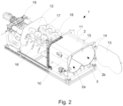
- Fig. 2 shows an exemplary mixing arrangement for the apparatus 1.
- the food product may be a beverage product, such as a dairy beverage or a non-dairy beverage.
- the beverage product may include milk or soft drinks.
- the food product may include other non-beverage food products such as ice cream, yogurt, or cheese.
- the product powder may include any suitable ingredient to form the desired food product.
- the product powder may include raw materials such as sugar, milk powder salt, or flour, or finished product such as instant formula, instant drinks, or dry broth. Other product powders may be suitable.
- the apparatus 1 may not necessarily be used to stir or mix the food product powder.
- the apparatus 1 may be used to transport the product powder and the nozzle arrangement 6 may be used for cleaning the apparatus 1 after the product powder is removed from the container 2.
- the interior surface 3 of the container 2 is defined by a first side wall 10, a second side wall 11 that is opposite the first side wall 10, and a back wall 12 of the container 2 that extends between the first side wall 10 and the second side wall 11.
- a front wall 13 is arranged opposite the back wall 12.
- the front wall 13 may be formed as a pivotable door for the container 2 and may be attached to the container 2 via handles and hinges 14.
- a top surface or ceiling 15 extends between the first side wall 10 and the second side wall 11, and between the back wall 12 and the front wall 13.
- the side walls 10, 11 may be angled relative to the ceiling 15 that extends horizontally.
- the container 2 and the interior surface 3 may have any suitable shape and the shape may be dependent on the application, such as whether the container 2 is used for housing a mixing or stirring arrangement, or for transport.
- a rotatable stirring device 16, 17 for stirring or mixing the product powder may be mounted to the back wall 12 and extend through the volume 4 of the container 2 when the apparatus 1 is assembled.
- the rotatable stirring device 16, 17 may include a first rotatable shaft 16 and a second rotatable shaft 17 that each includes mixing paddles 18.
- the rotatable shafts 16, 17 rotate in same or in an opposite rotational direction relative to each other during mixing of the product powder.
- the shape of the container 2 may be formed to accommodate rotation of the first rotatable shaft 16 and the second rotatable shaft 17.
- the side walls 10, 11 of the container 2 may each be formed to have a concave shape on their interior sides at the bottom of the container 2 such that each of the rotatable shafts 16, 17 are accommodated in a circular cavity 2a, 2b of the container 2.
- Other shapes may be suitable for the container 2.
- An engine 19 is arranged outside the container 2 and is coupled to the rotatable stirring device 16, 17 for rotation thereof. Any suitable engine or drive mechanism may be provided.
- the nozzle arrangement 6 includes a plurality of sets of jet nozzles 7, 8, 9 that are mounted to the container 2 and arranged to direct a flow of air towards the interior surface 3.
- the distribution of the sets of jet nozzles 7, 8, 9 in the nozzle arrangement 5 is dependent on the shape of the container 2.
- the sets of jet nozzles 7, 8, 9 are arranged to ensure coverage of an entire area of the interior surface 3, meaning that product powder may be removed from the entire surface area of the interior surface 3.
- the sets of jet nozzles 7, 8, 9 may have an unsymmetrical distribution along the interior surface 3 of the container 2 and each jet nozzle in the sets of jet nozzles 7, 8, 9 may be arranged tangentially relative to a respective wall 10, 11, 12, 13.
- Each set of jet nozzles 7, 8, 9 may correspond to a different wall 10, 11, 12, 13 for directing air at the respective wall 10, 11, 12, 13. Jet nozzles within a single set may be evenly spaced and mounted in a similar orientation relative to the same wall 10, 11, 12, 13.
- a first set of jet nozzles 7 includes jet nozzles 7, 20 that are arranged to direct a flow of air towards the side walls 10, 11.
- the jet nozzles 7, 20 may be evenly spaced and are angled relative to the respective side wall 10, 11.
- the jet nozzles 7 correspond to the first side wall 10 and the jet nozzles 20 correspond to the second side wall 11.
- Any suitable number of jet nozzles 7, 20 may be used, such as three or more jet nozzles per side wall 10, 11.
- Each side wall 10, 11 may have four jet nozzles that are arranged at an upper location along the respective side wall 10, 11 and configured to direct air at the respective wall 10, 11.
- the jet nozzles 7 corresponding to the first side wall 10 may have the same orientation and angle relative to the first side wall 10.
- the jet nozzles 20 corresponding to the second side wall 11 may have the same orientation and angle relative to the second side wall 11.
- the jet nozzles 7 and the jet nozzles 20 may be symmetrically arranged relative to each other to direct air flow downwardly along the respective side wall 10, 11 for powder removal therefrom.
- a second set of jet nozzles 7 includes jet nozzles 8, 21 that are arranged to direct a flow of air towards the ceiling 15 for removing product powder therefrom.
- the second set of jet nozzles 8, 21 may be arranged perpendicular relative to the first set of jet nozzles 8, 20 such that the second set of jet nozzles 8, 21 are arranged along a line that is parallel with the back wall 12 and the front wall 13 whereas the first set of jet nozzles 7, 20 are arranged along a line that is parallel with the side walls 10, 11.
- the jet nozzles 8 are arranged proximate the back wall 12 and the jet nozzles 21 are arranged opposite the jet nozzles 8 and proximate the front wall 13 (shown in Fig. 2 ).
- the jet nozzles 8 and the jet nozzles 21 may be symmetrically arranged relative to each other such that each set of jet nozzles 8, 21 directs air flow along the ceiling 15 towards the opposite set of jet nozzles 8, 21. Any suitable number of jet nozzles 8, 21 may be used, such as three or more jet nozzles. Four jet nozzles may be arranged proximate each of the back wall 12 and the front wall 13.
- a third set of jet nozzles 9 includes jet nozzles 9, 22 that are arranged to direct a flow of air towards a center of the container 2 or any other common location for collection of the removed powder.
- the jet nozzles 9, 22 may be angled away from the ceiling 15 and the side walls 10, 11 to direct airflow that moves the removed powder from the ceiling and the side walls 10, 11 toward the center of the container 2, such that the air and the powder may be drawn out of the container from the powder outlet 5.
- the jet nozzles 9 may be arranged proximate the first side wall 10 and the jet nozzles 22 may be arranged proximate the second side wall 11.
- the jet nozzles 9, 22 may be symmetrically arranged relative to each other. Any suitable number of jet nozzles 9, 22 may be used. Three jet nozzles may be arranged proximate each of the side walls 10, 11.
- the first, second, and third sets of jet nozzles 7, 8, 9 may be operated at different times and different jet nozzles within a set may also be operated at different times. Operation of each jet nozzle in the nozzle arrangement 6 may be controlled using a control valve 23 for each jet nozzle that independently controls the air passing through the respective jet nozzle.
- the control valves 23 may include any suitable activation device, such as a solenoid.
- Each control valve 23 is fluidly connected to a source of pressurized air (not shown) via a supply line 24.
- the source of pressurized air is connected to the supply line 24 via an air supply pipe (not shown).
- the supplied air may be filtered, sterilized, or dried and the source may be a compressor.
- the amount of air pressure in the supply line 24 may be maintained at a constant value.
- the control valves 23 corresponding to the first and second sets of jet nozzles 7, 8 may first be opened to direct air flow at the ceiling 15 and the side walls 10, 11 to remove the powder.
- the first and second sets of jet nozzles 7, 8 may be closed and the control valves 23 corresponding to the third set of jet nozzles 9 may be opened to direct the removed powder and the air toward the center of the container 2.
- Suction from a vacuum pump 46 (schematically shown in Fig. 6 ) that is connected to the powder outlet 5 may be used to draw the removed powder and the air out of the container 2 through the powder outlet 5.
- the powder outlet 5 may be opened and closed via a valve located in a passage of the powder outlet. This valve is operable by an actuator 25 that is configured to open and close the valve.
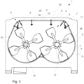
- FIG. 3 a front sectional view of the apparatus 1 including the nozzle arrangement 6 and the rotatable stirring device 16, 17 is shown.
- Fig. 3 shows pipes 26 that are configured for both supplying air to the corresponding jet nozzle and for mounting each jet nozzle 7, 8, 9 to the container 2.
- the pipes 26 may be welded to the periphery of the container 2 and extend into the volume 4 to hold the jet nozzles 7, 8, 9 within the container 2.
- Each pipe 26 is fluidly connected to a respective control valve 23 and to the supply line 24 shown in Fig. 1 .
- the supply line 24 may also be formed of piping that branches through the container 2.
- the nozzle arrangement 6 may be secured to the container 2 using any other suitable mounts, brackets, clamps, hooks, bolts, screws, and the like.
- Each jet nozzle 7, 8, 9 is arranged to direct the flow of air at the respective surface such that the flow of air impacts the surface at a predetermined impact angle.
- the first set of jet nozzles 7 that correspond to the side walls 10, 11 includes jet nozzles that are arranged to direct the flow of air towards the first or second side wall 10, 11 at an impact angle ⁇ 1 that is between 5 and 25 degrees relative to the respective side wall 10, 11.
- the impact angle ⁇ 1 may be between 10 and 20 degrees, or between 12 and 18 degrees.
- the impact angle ⁇ 1 may be defined as the angle between the flow direction F of the air and the tangential direction T of the surface at the point of impact 28 of the air flow.
- the point of impact 28 of the air flow on the respective side wall 10, 11 may be between 10 and 80 centimeters from the outlet of the jet nozzle 7, or even outside this range.
- the third set of jet nozzles 9 are angled away from the walls 10, 11 to direct the flow of air towards a horizontal center-plane C of the container 2.
- the center plane C may be defined as a horizontal plane that divides the volume 4 into two volumes of equal size.
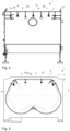
- the pipes 26 for the second set of jet nozzles 8 may alternatively as illustrated in Fig. 4 be attached to the back wall 12 or the front wall 13.
- the second set of jet nozzles 8 are arranged to direct the flow of air towards the ceiling 15.
- the impact angle ⁇ 2 of the flow of air hitting the ceiling 15 is between 5 and 25 degrees relative to the ceiling 15.
- the impact angle ⁇ 2 may be between 10 and 20 degrees, or even between 8 and 18 degrees.
- the point of impact 29 of the air flow on the ceiling 15 may be between 10 and 80 centimeters from the outlet of the jet nozzle 8, or may even be outside this range. As best shown in Fig.
- each of the jet nozzles 7, 8, 9 may include a flat fan nozzle having a fan-shaped outlet 30 that is configured to eject the air in a fan-shaped air flow pattern across the corresponding surface.
- Other types of nozzles may be suitable and the different sets of jet nozzles 7, 8, 9 may have the same or types of nozzles.
- Air may be fed to the sets of jet nozzles 7, 8, 9 at any suitable flow rate. Feeding the air may occur at a flow rate that is between 40 and 200 normal cubic meters per hour (Nm 3 /h) per square meter of the area of the interior surface 3 of the container 2.
- a "normal cubic meter” means one cubic meter of air at a temperature of zero degrees at a pressure of 1.01325 bar. Feeding the air may also occur at a flow rate that is between 40 and 200 cubic meters per hour, where the air has the same temperature and pressure as the air surrounding the apparatus 1.
- the interior surface area may include the area of the rotatable stirring device 16, 17 (shown in Figs. 2 and 3 ) or any other mixing device arranged in the container 2.
- Feeding the air may include varying the air flow through at least one of the jet nozzles 7, 8, 9 to temporarily increase the air flow through the corresponding jet nozzle 7, 8, 9, such that the air supply is pulsated.
- the flow rate during feeding is dependent on the application and in exemplary applications, feeding the air may occur at a flow rate that is between 110 and 130 Nm 3 /h, or between 110 and 130 m 3 /h (surrounding temperature and pressure).
- Feeding the air to the jet nozzles 7, 8, 9 may include feeding the air with a flow rate that provides a velocity of the air that is at least 5 meters per second (m/s) at the point of impact 28.
- Air may be drawn from the container 2 at any suitable flow rate. Drawing the air from the container 2 may occur at a flow rate that is between 60 and 240 Nm 3 /h, or between 60 and 240 m 3 /h (surrounding temperature and pressure), per square meter of the area of the interior surface 3 of the container 2. The flow rate during drawing is dependent on the application and in exemplary applications, drawing the air may occur at a flow rate that is between 130 and 150 Nm 3 /h, or between 130 and 150 m 3 /h (surrounding temperature and pressure).
- the first set of jet nozzles 7 may be configured to direct a flow of air 31 downwardly along the side walls 10, 11.
- the shape of the container 2 may force the air to flow concavely upwardly from a bottom of the container 2 toward the horizontal center-plane C.
- the second set of jet nozzles 8 may be configured to direct a flow of air 32 along the ceiling 15.
- the flow of air 32 may be directed from the back of the container 2 toward the front of the container 2 or vice versa, such that the air hits the front and back walls 12, 13 (shown in Fig. 2 ) after the air passes the ceiling 15.
- the third set of jet nozzles 9 are configured to direct a flow of air 33 toward the horizontal center-plane C of the container 2.
- the nozzles may be operated intermittent so that no air flows collides and interfere with each other.
- Fig. 6 shows an exemplary control system 45 for the apparatus 1.
- the cleaning process may be automated using the control system 45 which includes a processor 34 that is communicatively coupled with the control valves 23 for activation of the control valves 23, and a pneumatic conveying system 35 that is configured to supply air to the nozzle arrangement 6.
- the control valves 23 may be solenoid valves and the processor 34 may include any suitable processors and electronic control mechanisms, such as, for example, a central processing unit (CPU), a microprocessor, control circuitry, and the like.
- CPU central processing unit
- microprocessor microprocessor
- the pneumatic conveying system 35 may include a compressor and the control system 45 may control the compressor to feed the air to the supply line 24 at the predetermined flow rate, e.g. a flow rate that is between 40 and 200 Nm 3 /h.
- the control system 45 may be used to maintain constant pressure in the supply line 24.
- the processor 34 may activate the jet nozzles 7, 8, 9 of the nozzle arrangement 6 sequentially, such that the feeding of air to the container 2 provides an air flow that varies over time through the jet nozzles.
- the control system 45 may also be used to vary the air flow through at least one of the jet nozzles to temporarily increase the air flow through the jet nozzle. Any specific sequence of air flow in the container 2 may be provided using the control system 45. Pulsated air flow, alternating air flow speeds, and different flow rates for different jet nozzles may be provided.
- the pneumatic conveying system 35 may also be fluidly connected to the vacuum pump 25 for creating a suction effect that draws the air and the powder out of the powder outlet 5 of the container 2 (shown in Fig. 1 ).
- the vacuum pump 46 may be operable independently from the nozzle arrangement 6.
- the container 2 may be enclosed such that air may only exit through the powder outlet 5. If more air is drawn out of the container 2 than is being supplied to the container 2, the container 2 may include another additional inlet valve 36 for supplying more air into the container 2.
- the inlet valve 36 may be a one-way valve that enables air to unilaterally pass through the valve into the supply line 24 for the container 2.
- the inlet valve 36 may be arranged as part of the container 2 or outside the container 2.
- any suitable sensor 37 such as a pressure sensor for detecting pressure in the supply line 24, may be a part of the apparatus 1 such that the processor 34 may activate the inlet valve 36 and the control valves 23 in response to the detected data by the sensor 37.
- the inlet valve 36 is a regular, mechanical pressure (vacuum) relief valve.
- a method 38 for cleaning an apparatus for handling a food product powder is shown.
- the apparatus 1 shown in Figs. 1-5 and the control system 45 shown in Fig. 6 may be used to perform the method 38.
- the method 38 includes a step 39 of feeding air into the container 2 using the nozzle arrangement 6 that is attached to the container 2.
- the air is directed by a plurality of jet nozzles 7, 8, 9 towards the interior surface 3 to remove product powder from the interior surface 3.
- Step 39 may include feeding the air into the container 2 with a flow rate of between 40 and 200 Nm 3 /h per m 2 of interior surface area of the container 2, or with another flow rate as previously indicated.
- Step 39 may include feeding the air into the container 2 with a flow rate that provides a velocity of the air of at least 5 m/s at a point of impact 28, 29 of the air against the interior surface 3 of the container 2.
- Step 39 may include varying the air flow through at least one of the jet nozzles 7, 8, 9 to thereby temporarily increase the air flow through at least one jet nozzle 7, 8, 9 and cause powder release from the interior surface 3.
- a step 40 of the method 38 includes activating the jet nozzles 7, 8, 9.
- Step 40 may include activating the jet nozzles 7, 8, 9 sequentially, such that the feeding of air into the container 2 provides an air flow that varies over time through the jet nozzles 7, 8, 9.
- Step 40 may include activating jet nozzles for powder removal and a step 41 may include activating jet nozzles for directing the removed powder to the center of the container 2.
- the first set of jet nozzles 7 and the second set of jet nozzles 8 may be activated and during step 41, the third set of jet nozzles 9 may be activated.
- the activation of the jet nozzles during either step 40 or during step 42 may also be activated sequentially.
- a step 42 of the method 38 includes drawing air out from the container 2, such that air and the removed product powder may flow out of the container 2 via the powder outlet 5.
- Step 42 may include drawing the air from the container 2 at a flow rate of a 60-240 Nm 3 /h per m 3 volume defined by the interior surface 3 of the container 2, or drawing air at another flow rate as previously indicated.
- the method 38 is a dry-cleaning method, i.e. no liquid is supplied into the sealable container 2 when the method is performed.
- the apparatus 1 for handling a food product powder including the nozzle arrangement 6 is advantageous in providing more efficient cleaning of the apparatus.
- the jet nozzles in the nozzle arrangement are configured to direct a flow of air at an interior surface of the sealable container to remove the residual product powder from the interior surface.
- the removed product powder and the air may flow out of the container via the powder outlet and a vacuum pump, such that the manual cleaning process for the apparatus may be less intensive or eliminated.
- using the nozzle arrangement advantageously enables a more sanitary cleaning process due to the container being able to remain sealed during the cleaning process.
Landscapes
- Life Sciences & Earth Sciences (AREA)
- Chemical & Material Sciences (AREA)
- Engineering & Computer Science (AREA)
- Food Science & Technology (AREA)
- Polymers & Plastics (AREA)
- Microbiology (AREA)
- Health & Medical Sciences (AREA)
- Nutrition Science (AREA)
- Cleaning In General (AREA)
- General Preparation And Processing Of Foods (AREA)
Description
- The invention relates to a device and method for cleaning an apparatus for handling a food product power.
- Product powders may be used to produce various food products. Using product powders are advantageous in that the powder may be stored for long periods of time without being spoiled. The powder may also be easily dissolved in a liquid to form the desired product. Food products formed by powders may include dairy beverages, such as milk, non-dairy beverages, such as soft drinks, and other dairy products such as ice cream, yogurt, or cheese. Product powders may include raw materials such as sugar, milk powder, salt, or flour, or finished products such as instant formula, instant drinks, or dry broth. In producing a milk alternative that resembles fresh dairy milk, raw milk powder may be used. The raw milk powder dissolves easily in water to form a reconstituted liquid milk that undergoes further processing, including filtration, homogenization, and heat treatment, to form the final beverage product. Other form of food product powders are such ingredients that are mixed together to form bake mixtures and cake mixtures.
- Product powders may require a mixing process which often occurs in a sealable container including a stirring arrangement, paddle mixers, or other suitable mixing devices. After mixing and emptying the product mixture from the sealable container, a residual powder may remain on the interior walls of the sealable container. A conventional method for cleaning the interior walls includes maintenance personnel manually removing the powder using industrial vacuum cleaners. The conventional cleaning method is deficient in that the cleaning process is labor-intensive. The conventional cleaning method may also require opening the container causing the container interior to be susceptible to contamination.
- Apparatuses for handling powder, some of which describe cleaning, are disclosed in patent documents
EP3513882A1 ,DE102013006822A1 ,DE102011112016B3 ,US3697286A ,CN 1 07824368AUS2019/329201A1 . An apparatus for the mixing of bulk material which comprises a cleaning system is described inEP 2 777 831 A1 - It is an object of the invention to at least partly overcome one or more limitations of the prior art. In particular, it is an object to provide a device and method that accomplish efficient cleaning of an apparatus for handling a food product powder.
- According to an aspect of the invention, an apparatus according to
claim 1 is provided for handling a food product powder. - The apparatus includes a sealable container having an interior surface defining a volume in which the food product powder is handled, and a powder outlet, and a nozzle arrangement that is attached to the container and configured to feed air into the container. The nozzle arrangement includes a plurality of jet nozzles configured to direct the air towards the interior surface to remove product powder from the interior surface, such that the air and the removed product powder may flow out of the container via the powder outlet. Said apparatus is characterized in that it is a mixing apparatus that comprises at least one rotatable stirring device for the food product powder, the jet nozzles are arranged to ensure coverage of an entire area of the interior surface, such that the product powder may be removed from the entire surface area of the interior surface, and the interior surface area includes the area of the rotatable stirring device.
- Accordingly, the cleaning according to the invention is not done in the traditional way, i.e. by opening the container and manually using a vacuum cleaner to remove the powder from the interior surface and out of the container. Instead, the powder is removed from the interior surface using the jet nozzles that direct the air towards the interior surface, and the removed powder and air may be drawn out of the container. The apparatus for handling a food product powder described herein is advantageous in that the apparatus enables cleaning in a very efficient and sanitary manner. The container may remain closed during the cleaning process. The apparatus includes multiple sets of jet nozzles that are arranged to direct the flow of air towards different walls of the container, and the jet nozzles may be arranged to have a predetermined impact angle of the flow of air hitting the respective surface. The arrangement of the jet nozzles is advantageous in ensuring that the powder is removed from the respective surface such that it may be drawn out of the container.
- According to another aspect of the invention, a method for cleaning according to
claim 9 is used for an apparatus for handling a food product powder that includes a sealable container having an interior surface defining a volume in which the food product powder is handled, and a powder outlet, the apparatus being a mixing apparatus that comprises at least one rotatable stirring device for the food product powder, - The method includes feeding air into the container using a nozzle arrangement that is attached to the container, wherein the air is directed by a plurality of jet nozzles towards the interior surface to remove product powder from the interior surface, and drawing air out from the container, such that air and the removed product powder may flow out of the container via the powder outlet. Said method is characterized in having the jet nozzles arranged to ensure coverage of an entire area of the interior surface, such that the product powder may be removed from the entire surface area of the interior surface, and the interior surface area including the area of the rotatable stirring device.
- This method may include the same features as the apparatus for handling a food product powder and shares the same advantages.
- Still other objectives, features, aspects and advantages of the invention will appear from the following detailed description as well as from the drawings.
- Features of the invention will now be described, by way of example, with reference to the accompanying schematic drawings.
-
Fig. 1 is a perspective sectional view of an apparatus for handling a food product powder. -
Fig. 2 is a perspective sectional view of the apparatus for handling a food product powder ofFig. 1 including a stirring arrangement. -
Fig. 3 is a front sectional view of the apparatus ofFig. 1 . -
Fig. 4 is a side sectional view of the apparatus ofFig. 1 . -
Fig. 5 is a front sectional view of the apparatus ofFig. 1 showing an air flow path in the container. -
Fig. 6 is a schematic drawing of a control system for the apparatus ofFig. 1 . -
Fig. 7 is a flow chart of a method for cleaning an apparatus like the apparatus ofFig. 1 . - Embodiments of the invention will now be described more fully hereinafter with reference to the accompanying drawings, in which some, but not all, embodiments of the invention are shown. The invention may be embodied in many different forms and should not be construed as limited to the embodiments set forth herein.
- Referring first to
Fig. 1 , anapparatus 1 for handling a food product powder is shown. Theapparatus 1 includes asealable container 2 having aninterior surface 3 that defines avolume 4 in which the food product powder is handled, and apowder outlet 5. Theapparatus 1 may be oriented horizontally such that thepowder outlet 5 is arranged at a bottom of theapparatus 1. Anozzle arrangement 6 is attached to thecontainer 2 and is configured to feed air into thecontainer 2 for removing residual food product powder from thecontainer 2 during a cleaning process that occurs after as much as possible of the food product powder has been removed from thecontainer 2 for packaging or further processing. Thenozzle arrangement 6 includes a plurality ofjet nozzles interior surface 3 to remove the product powder from theinterior surface 3. After the product powder is removed from theinterior surface 3, the air and the removed product powder exit thecontainer 2 via thepowder outlet 5. - Referring in addition to
Fig. 2 , handling the food product powder in thecontainer 2 may include stirring or mixing the food product powder to produce the food product.Fig. 2 shows an exemplary mixing arrangement for theapparatus 1. The food product may be a beverage product, such as a dairy beverage or a non-dairy beverage. The beverage product may include milk or soft drinks. The food product may include other non-beverage food products such as ice cream, yogurt, or cheese. The product powder may include any suitable ingredient to form the desired food product. The product powder may include raw materials such as sugar, milk powder salt, or flour, or finished product such as instant formula, instant drinks, or dry broth. Other product powders may be suitable. Theapparatus 1 may not necessarily be used to stir or mix the food product powder. For example, theapparatus 1 may be used to transport the product powder and thenozzle arrangement 6 may be used for cleaning theapparatus 1 after the product powder is removed from thecontainer 2. - The
interior surface 3 of thecontainer 2 is defined by afirst side wall 10, asecond side wall 11 that is opposite thefirst side wall 10, and aback wall 12 of thecontainer 2 that extends between thefirst side wall 10 and thesecond side wall 11. As shown inFig. 2 , afront wall 13 is arranged opposite theback wall 12. Thefront wall 13 may be formed as a pivotable door for thecontainer 2 and may be attached to thecontainer 2 via handles and hinges 14. A top surface orceiling 15 extends between thefirst side wall 10 and thesecond side wall 11, and between theback wall 12 and thefront wall 13. Theside walls ceiling 15 that extends horizontally. Thecontainer 2 and theinterior surface 3 may have any suitable shape and the shape may be dependent on the application, such as whether thecontainer 2 is used for housing a mixing or stirring arrangement, or for transport. - As shown in
Fig. 2 , arotatable stirring device back wall 12 and extend through thevolume 4 of thecontainer 2 when theapparatus 1 is assembled. Therotatable stirring device rotatable shaft 16 and a secondrotatable shaft 17 that each includes mixing paddles 18. Therotatable shafts container 2 may be formed to accommodate rotation of the firstrotatable shaft 16 and the secondrotatable shaft 17. Theside walls container 2 may each be formed to have a concave shape on their interior sides at the bottom of thecontainer 2 such that each of therotatable shafts circular cavity container 2. Other shapes may be suitable for thecontainer 2. Anengine 19 is arranged outside thecontainer 2 and is coupled to therotatable stirring device - The
nozzle arrangement 6 includes a plurality of sets ofjet nozzles container 2 and arranged to direct a flow of air towards theinterior surface 3. The distribution of the sets ofjet nozzles nozzle arrangement 5 is dependent on the shape of thecontainer 2. The sets ofjet nozzles interior surface 3, meaning that product powder may be removed from the entire surface area of theinterior surface 3. The sets ofjet nozzles interior surface 3 of thecontainer 2 and each jet nozzle in the sets ofjet nozzles respective wall jet nozzles different wall respective wall same wall - Three different sets of
jet nozzles Fig. 1 . A first set ofjet nozzles 7 includesjet nozzles side walls jet nozzles respective side wall jet nozzles 7 correspond to thefirst side wall 10 and thejet nozzles 20 correspond to thesecond side wall 11. Any suitable number ofjet nozzles side wall side wall respective side wall respective wall jet nozzles 7 corresponding to thefirst side wall 10 may have the same orientation and angle relative to thefirst side wall 10. Similarly, thejet nozzles 20 corresponding to thesecond side wall 11 may have the same orientation and angle relative to thesecond side wall 11. Thejet nozzles 7 and thejet nozzles 20 may be symmetrically arranged relative to each other to direct air flow downwardly along therespective side wall - A second set of
jet nozzles 7 includesjet nozzles ceiling 15 for removing product powder therefrom. The second set ofjet nozzles jet nozzles jet nozzles back wall 12 and thefront wall 13 whereas the first set ofjet nozzles side walls jet nozzles 8 are arranged proximate theback wall 12 and thejet nozzles 21 are arranged opposite thejet nozzles 8 and proximate the front wall 13 (shown inFig. 2 ). Thejet nozzles 8 and thejet nozzles 21 may be symmetrically arranged relative to each other such that each set ofjet nozzles ceiling 15 towards the opposite set ofjet nozzles jet nozzles back wall 12 and thefront wall 13. - A third set of
jet nozzles 9 includesjet nozzles container 2 or any other common location for collection of the removed powder. Thejet nozzles ceiling 15 and theside walls side walls container 2, such that the air and the powder may be drawn out of the container from thepowder outlet 5. Thejet nozzles 9 may be arranged proximate thefirst side wall 10 and thejet nozzles 22 may be arranged proximate thesecond side wall 11. Thejet nozzles jet nozzles side walls - The first, second, and third sets of
jet nozzles nozzle arrangement 6 may be controlled using acontrol valve 23 for each jet nozzle that independently controls the air passing through the respective jet nozzle. Thecontrol valves 23 may include any suitable activation device, such as a solenoid. Eachcontrol valve 23 is fluidly connected to a source of pressurized air (not shown) via asupply line 24. The source of pressurized air is connected to thesupply line 24 via an air supply pipe (not shown). The supplied air may be filtered, sterilized, or dried and the source may be a compressor. The amount of air pressure in thesupply line 24 may be maintained at a constant value. - During the cleaning process, the
control valves 23 corresponding to the first and second sets ofjet nozzles ceiling 15 and theside walls interior surface 3, the first and second sets ofjet nozzles control valves 23 corresponding to the third set ofjet nozzles 9 may be opened to direct the removed powder and the air toward the center of thecontainer 2. Suction from a vacuum pump 46 (schematically shown inFig. 6 ) that is connected to thepowder outlet 5 may be used to draw the removed powder and the air out of thecontainer 2 through thepowder outlet 5. Thepowder outlet 5 may be opened and closed via a valve located in a passage of the powder outlet. This valve is operable by anactuator 25 that is configured to open and close the valve. - Referring now to
Fig. 3 , a front sectional view of theapparatus 1 including thenozzle arrangement 6 and therotatable stirring device Fig. 3 showspipes 26 that are configured for both supplying air to the corresponding jet nozzle and for mounting eachjet nozzle container 2. Thepipes 26 may be welded to the periphery of thecontainer 2 and extend into thevolume 4 to hold thejet nozzles container 2. Eachpipe 26 is fluidly connected to arespective control valve 23 and to thesupply line 24 shown inFig. 1 . Thesupply line 24 may also be formed of piping that branches through thecontainer 2. Thenozzle arrangement 6 may be secured to thecontainer 2 using any other suitable mounts, brackets, clamps, hooks, bolts, screws, and the like. - Each
jet nozzle jet nozzles 7 that correspond to theside walls second side wall respective side wall impact 28 of the air flow. The point ofimpact 28 of the air flow on therespective side wall jet nozzle 7, or even outside this range. As also shown inFig. 3 , the third set ofjet nozzles 9 are angled away from thewalls container 2. The center plane C may be defined as a horizontal plane that divides thevolume 4 into two volumes of equal size. - Referring now to
Fig. 4 , a side view of theapparatus 1 is shown. Thepipes 26 for the second set ofjet nozzles 8 may alternatively as illustrated inFig. 4 be attached to theback wall 12 or thefront wall 13. The second set ofjet nozzles 8 are arranged to direct the flow of air towards theceiling 15. The impact angle θ2 of the flow of air hitting theceiling 15 is between 5 and 25 degrees relative to theceiling 15. The impact angle θ2 may be between 10 and 20 degrees, or even between 8 and 18 degrees. The point ofimpact 29 of the air flow on theceiling 15 may be between 10 and 80 centimeters from the outlet of thejet nozzle 8, or may even be outside this range. As best shown inFig. 4 , each of thejet nozzles outlet 30 that is configured to eject the air in a fan-shaped air flow pattern across the corresponding surface. Other types of nozzles may be suitable and the different sets ofjet nozzles - Referring now to
Fig. 5 , an air flow path in thecontainer 2 of theapparatus 1 is shown. The air flow path may be continuous around theinterior surface 3. Air may be fed to the sets ofjet nozzles interior surface 3 of thecontainer 2. A "normal cubic meter" means one cubic meter of air at a temperature of zero degrees at a pressure of 1.01325 bar. Feeding the air may also occur at a flow rate that is between 40 and 200 cubic meters per hour, where the air has the same temperature and pressure as the air surrounding theapparatus 1. The interior surface area may include the area of therotatable stirring device 16, 17 (shown inFigs. 2 and3 ) or any other mixing device arranged in thecontainer 2. Feeding the air may include varying the air flow through at least one of thejet nozzles jet nozzle jet nozzles impact 28. - Air may be drawn from the
container 2 at any suitable flow rate. Drawing the air from thecontainer 2 may occur at a flow rate that is between 60 and 240 Nm3/h, or between 60 and 240 m3/h (surrounding temperature and pressure), per square meter of the area of theinterior surface 3 of thecontainer 2. The flow rate during drawing is dependent on the application and in exemplary applications, drawing the air may occur at a flow rate that is between 130 and 150 Nm3/h, or between 130 and 150 m3/h (surrounding temperature and pressure). - As shown in
Fig. 5 , the first set ofjet nozzles 7 may be configured to direct a flow ofair 31 downwardly along theside walls container 2 may force the air to flow concavely upwardly from a bottom of thecontainer 2 toward the horizontal center-plane C. The second set ofjet nozzles 8 may be configured to direct a flow ofair 32 along theceiling 15. The flow ofair 32 may be directed from the back of thecontainer 2 toward the front of thecontainer 2 or vice versa, such that the air hits the front andback walls 12, 13 (shown inFig. 2 ) after the air passes theceiling 15. The third set ofjet nozzles 9 are configured to direct a flow of air 33 toward the horizontal center-plane C of thecontainer 2. The nozzles may be operated intermittent so that no air flows collides and interfere with each other. -
Fig. 6 shows anexemplary control system 45 for theapparatus 1. The cleaning process may be automated using thecontrol system 45 which includes aprocessor 34 that is communicatively coupled with thecontrol valves 23 for activation of thecontrol valves 23, and a pneumatic conveying system 35 that is configured to supply air to thenozzle arrangement 6. Thecontrol valves 23 may be solenoid valves and theprocessor 34 may include any suitable processors and electronic control mechanisms, such as, for example, a central processing unit (CPU), a microprocessor, control circuitry, and the like. - The pneumatic conveying system 35 may include a compressor and the
control system 45 may control the compressor to feed the air to thesupply line 24 at the predetermined flow rate, e.g. a flow rate that is between 40 and 200 Nm3/h. Thecontrol system 45 may be used to maintain constant pressure in thesupply line 24. Theprocessor 34 may activate thejet nozzles nozzle arrangement 6 sequentially, such that the feeding of air to thecontainer 2 provides an air flow that varies over time through the jet nozzles. Thecontrol system 45 may also be used to vary the air flow through at least one of the jet nozzles to temporarily increase the air flow through the jet nozzle. Any specific sequence of air flow in thecontainer 2 may be provided using thecontrol system 45. Pulsated air flow, alternating air flow speeds, and different flow rates for different jet nozzles may be provided. - The pneumatic conveying system 35 may also be fluidly connected to the
vacuum pump 25 for creating a suction effect that draws the air and the powder out of thepowder outlet 5 of the container 2 (shown inFig. 1 ). Thevacuum pump 46 may be operable independently from thenozzle arrangement 6. Thecontainer 2 may be enclosed such that air may only exit through thepowder outlet 5. If more air is drawn out of thecontainer 2 than is being supplied to thecontainer 2, thecontainer 2 may include anotheradditional inlet valve 36 for supplying more air into thecontainer 2. Theinlet valve 36 may be a one-way valve that enables air to unilaterally pass through the valve into thesupply line 24 for thecontainer 2. Theinlet valve 36 may be arranged as part of thecontainer 2 or outside thecontainer 2. Anysuitable sensor 37, such as a pressure sensor for detecting pressure in thesupply line 24, may be a part of theapparatus 1 such that theprocessor 34 may activate theinlet valve 36 and thecontrol valves 23 in response to the detected data by thesensor 37. Alternatively, theinlet valve 36 is a regular, mechanical pressure (vacuum) relief valve. - Referring now to
Fig. 7 , amethod 38 for cleaning an apparatus for handling a food product powder is shown. Theapparatus 1 shown inFigs. 1-5 and thecontrol system 45 shown inFig. 6 may be used to perform themethod 38. Themethod 38 includes astep 39 of feeding air into thecontainer 2 using thenozzle arrangement 6 that is attached to thecontainer 2. The air is directed by a plurality ofjet nozzles interior surface 3 to remove product powder from theinterior surface 3.Step 39 may include feeding the air into thecontainer 2 with a flow rate of between 40 and 200 Nm3/h per m2 of interior surface area of thecontainer 2, or with another flow rate as previously indicated.Step 39 may include feeding the air into thecontainer 2 with a flow rate that provides a velocity of the air of at least 5 m/s at a point ofimpact interior surface 3 of thecontainer 2.Step 39 may include varying the air flow through at least one of thejet nozzles jet nozzle interior surface 3. - A
step 40 of themethod 38 includes activating thejet nozzles Step 40 may include activating thejet nozzles container 2 provides an air flow that varies over time through thejet nozzles Step 40 may include activating jet nozzles for powder removal and astep 41 may include activating jet nozzles for directing the removed powder to the center of thecontainer 2. Duringstep 40, the first set ofjet nozzles 7 and the second set ofjet nozzles 8 may be activated and duringstep 41, the third set ofjet nozzles 9 may be activated. The activation of the jet nozzles during eitherstep 40 or duringstep 42 may also be activated sequentially. - A
step 42 of themethod 38 includes drawing air out from thecontainer 2, such that air and the removed product powder may flow out of thecontainer 2 via thepowder outlet 5.Step 42 may include drawing the air from thecontainer 2 at a flow rate of a 60-240 Nm3/h per m3 volume defined by theinterior surface 3 of thecontainer 2, or drawing air at another flow rate as previously indicated. Themethod 38 is a dry-cleaning method, i.e. no liquid is supplied into thesealable container 2 when the method is performed. - The
apparatus 1 for handling a food product powder including thenozzle arrangement 6 is advantageous in providing more efficient cleaning of the apparatus. The jet nozzles in the nozzle arrangement are configured to direct a flow of air at an interior surface of the sealable container to remove the residual product powder from the interior surface. The removed product powder and the air may flow out of the container via the powder outlet and a vacuum pump, such that the manual cleaning process for the apparatus may be less intensive or eliminated. In addition to providing a more efficient cleaning process, using the nozzle arrangement advantageously enables a more sanitary cleaning process due to the container being able to remain sealed during the cleaning process. - From the description above follows that, although various embodiments of the invention have been described and shown, the invention is not restricted thereto, but may also be embodied in other ways within the scope of the subject-matter defined in the following claims.
Claims (14)
- An apparatus (1) for handling a food product powder, the apparatus (1) comprising:a sealable container (2) having an interior surface (3) defining a volume (4) in which the food product powder is handled, and a powder outlet (5); anda nozzle arrangement (6) that is attached to the container (2) and configured to feed air into the container (2), whereinthe nozzle arrangement (6) comprises a plurality of jet nozzles (7, 8, 9) configured to direct the air towards the interior surface (3) to remove product powder from the interior surface (3), such that the air and the removed product powder may flow out of the container (2) via the powder outlet (5), characterized in thatthe apparatus (1) is a mixing apparatus that comprises at least one rotatable stirring device (16, 17) for the food product powder,the jet nozzles (7, 8, 9) are arranged to ensure coverage of an entire area of the interior surface (3), such that product powder may be removed from the entire surface area of the interior surface (3), andthe interior surface area includes the area of the rotatable stirring device (16, 17).
- The apparatus (1) according to claim 1, whereinthe interior surface (3) of the container (2) comprises a first side wall (10) and a second side wall (11) that is opposite the first side wall (10), andthe plurality of jet nozzles (7, 8, 9) comprises a first set of jet nozzles (7, 20) that is arranged to direct a flow of air (31) towards the first and second side walls (10, 11).
- The apparatus (1) according to claim 2, wherein the first set of jet nozzles (7, 20) is arranged to direct the flow of air (31) towards the first and second side walls (10, 11) such that the impact angle (θ1) of the flow of air (31) hitting the first and second side walls (10, 11) is between 5 and 25 degrees relative to the respective side wall (10, 11).
- The apparatus (1) according to any preceding claim, whereinthe interior surface (3) of the container (2) comprises a front wall (13) and a back wall (12) that is opposite the front wall (13), and a ceiling (15) that extends between the front wall (13) and the back wall (12), andthe plurality of jet nozzles (7, 8, 9) comprises a second set of jet nozzles (8, 21) that is arranged to direct a flow of air (32) towards the ceiling (15).
- The apparatus (1) according to claim 4, wherein the second set of jet nozzles (8, 21) is arranged to direct the flow of air (32) towards the ceiling (15) such that the impact angle (θ2) of the flow of air (32) hitting the ceiling (15) is between 5 and 25 degrees relative to the ceiling (15).
- The apparatus (1) according to any preceding claim, wherein the plurality of jet nozzles (7, 8, 9) comprises a third set of jet nozzles (9, 22) that is arranged to direct a flow of air (33) towards a horizontal center-plane (C) of the sealable container (2).
- The apparatus (1) according to any preceding claim, wherein the plurality of jet nozzles (7, 8, 9) comprises flat fan jet nozzles (30) that are arranged to eject the air in a fan-shaped air flow pattern.
- The apparatus (1) according to any preceding claim, wherein the nozzle arrangement (6) comprises a plurality of control valves (23) that are configured to independently control the flow of air through different jet nozzles of the plurality of jet nozzles (7, 8, 9), such that the flow of air is different through at least some of the different jet nozzles.
- A method (38) for cleaning an apparatus (1) for handling a food product powder, the apparatus (1) comprising a sealable container (2) having an interior surface (3) defining a volume (4) in which the food product powder is handled, a powder outlet (5), the apparatus (1) being a mixing apparatus that comprises at least one rotatable stirring device (16, 17) for the food product powder, the method (38) comprisingfeeding (39) air into the container (2) using a nozzle arrangement (6) that is attached to the container (2), wherein the air is directed by a plurality of jet nozzles (7, 8, 9) towards the interior surface (3) to remove product powder from the interior surface (3), anddrawing (42) air out from the container (2), such that air and the removed product powder may flow out of the container (2) via the powder outlet (5), characterized byhaving the jet nozzles (7, 8, 9) arranged to ensure coverage of an entire area of the interior surface (3), such that product powder is removed from the entire surface area of the interior surface (3), andthe interior surface area including the area of the rotatable stirring device (16, 17).
- The method (38) according to claim 9, wherein the feeding (39) of air comprises feeding the air into the sealable container (2) with a flow rate of between 40 and 200 Nm3/h per m2 of interior surface area of the sealable container (2).
- The method (38) according to claim 9 or 10, wherein the feeding (39) of air comprises feeding the air into the sealable container (2) with a flow rate that provides a velocity of the air of at least 5 m/s at a point of impact of the air against the interior surface (3) of the container (2).
- The method (38) according to any one of claims 9-11, wherein the drawing (42) of air comprises drawing the air from the sealable container (2) at a flow rate of a 60-240 Nm3/h per m3 volume defined by the interior surface (3) of the sealable container (2).
- The method (38) according to any one of claims 9-12, comprising activating (40) jet nozzles of the plurality of jet nozzles (7, 8, 9) sequentially, such that the feeding (39) of air provides an air flow that varies over time through the jet nozzles (7, 8, 9).
- The method (38) according to any one of claims 9-13, wherein the feeding (39) of air comprises varying the air flow through at least one of the jet nozzles of the plurality of jet nozzles (7, 8, 9), to thereby temporarily increase the air flow through said at least one jet nozzle (7, 8, 9) and make powder release from the interior surface (3).
Applications Claiming Priority (1)
| Application Number | Priority Date | Filing Date | Title |
|---|---|---|---|
| EP19218844 | 2019-12-20 |
Publications (2)
| Publication Number | Publication Date |
|---|---|
| EP3837986A1 EP3837986A1 (en) | 2021-06-23 |
| EP3837986B1 true EP3837986B1 (en) | 2025-06-18 |
Family
ID=69005320
Family Applications (1)
| Application Number | Title | Priority Date | Filing Date |
|---|---|---|---|
| EP20214857.3A Active EP3837986B1 (en) | 2019-12-20 | 2020-12-17 | Nozzle arrangement for a powder handling apparatus |
Country Status (5)
| Country | Link |
|---|---|
| US (1) | US12389921B2 (en) |
| EP (1) | EP3837986B1 (en) |
| CN (1) | CN114828639B (en) |
| AU (1) | AU2020406094A1 (en) |
| WO (1) | WO2021122916A1 (en) |
Families Citing this family (1)
| Publication number | Priority date | Publication date | Assignee | Title |
|---|---|---|---|---|
| CN116635166B (en) * | 2020-12-22 | 2026-01-02 | 利乐拉瓦尔集团及财务有限公司 | Nozzle of powder processing device |
Citations (29)
| Publication number | Priority date | Publication date | Assignee | Title |
|---|---|---|---|---|
| JPS4998380A (en) * | 1972-12-28 | 1974-09-18 | ||
| DE7824931U1 (en) | 1978-08-21 | 1978-12-14 | Mti-Mischtechnik Industrieanlagen Gmbh, 4930 Detmold | MIXING OR STIRRING DEVICE |
| US4141316A (en) * | 1976-01-23 | 1979-02-27 | Gustav Grun | Apparatus for the treatment of powdery or granular material |
| JPS5449351A (en) * | 1977-07-26 | 1979-04-18 | Hunter Valley Coop Dairy | Production of instant powder from liquid |
| EP0163217A2 (en) | 1984-05-30 | 1985-12-04 | Ritter-Plastic GmbH | Static mixer |
| DE8534830U1 (en) | 1985-12-11 | 1987-02-19 | BHS-Bayerische Berg-, Hütten- und Salzwerke AG, 8000 München | Twin-shaft compulsory mixer for continuous and discontinuous operation |
| EP0446825A1 (en) | 1990-03-16 | 1991-09-18 | GUSBI Officina Meccanica S.p.A. | Mixing apparatus with compressed-air cleaning device |
| WO1992015393A1 (en) | 1991-03-06 | 1992-09-17 | Blentech Corporation | Continuous compartmented mixer |
| JPH10309972A (en) * | 1997-05-13 | 1998-11-24 | Sanki Tsuuun Kk | Cleaning method of powder tank room of powder transport tank truck and cleaning plant used therefor |
| DE10024492A1 (en) | 2000-05-21 | 2002-01-24 | Femix Misch Und Knettechnik Gm | Vertical mixer comprises two conical mixing implements which are rotatable about their longitudinal axes oriented at an angle to one another |
| WO2002016016A1 (en) | 2000-08-24 | 2002-02-28 | Hilutec Systemtechnik Gmbh & Co. Kg | Device and method for mixing constituents |
| DE10196820T5 (en) | 2000-10-23 | 2004-04-15 | Guntert And Zimmermann Const. Div. Inc., Ripon | Large-volume double-shaft compulsory mixer |
| JP2004141772A (en) * | 2002-10-24 | 2004-05-20 | Nippon Pneumatic Mfg Co Ltd | Cleaning apparatus for powder transport passage and pulverization apparatus |
| WO2011107435A1 (en) * | 2010-03-05 | 2011-09-09 | Dürr Ecoclean GmbH | Tool for cleaning and/or drying a cavity |
| US20120138708A1 (en) * | 2009-08-19 | 2012-06-07 | Kirtan Shravan Kamkar | Process and a device to clean substrates |
| FR2984188A1 (en) * | 2011-12-20 | 2013-06-21 | Oce Printing Systems Gmbh | DEVICE FOR CLEANING THE DEPOSITS OF A COMPONENT |
| KR20140070862A (en) * | 2012-11-28 | 2014-06-11 | 볼보 컨스트럭션 이큅먼트 에이비 | dust removing device and construction machine |
| EP2777831A1 (en) * | 2013-03-14 | 2014-09-17 | m-tec mathis technik gmbh | Method for cleaning a bulk material mixer and bulk material mixer with mixing container to be cleaned |
| DE102013006822A1 (en) | 2013-04-22 | 2014-10-23 | Hermann Linder | Cleaning arrangement with a material storage container for the conveyor and cleaning methods |
| CN104550127A (en) * | 2015-01-19 | 2015-04-29 | 郑州佑飞机电科技有限公司 | Novel environmentally-friendly particular and powdered material surface cleaning system |
| CN105215001A (en) * | 2015-10-08 | 2016-01-06 | 格薪源生物质燃料有限公司 | Pulse of compressed air blast cleaning device |
| CN105414072A (en) * | 2015-12-23 | 2016-03-23 | 江苏七O七天然制药有限公司 | Purging device of spray-drying equipment |
| US20160271652A1 (en) * | 2013-07-24 | 2016-09-22 | Sharp Kabushiki Kaisha | Cleaning device |
| US20170000144A1 (en) * | 2015-02-04 | 2017-01-05 | Idaho Milk Products | Process for Manufacture of Milk Permeate Powders |
| DE102016003271B3 (en) * | 2016-03-18 | 2017-05-24 | Cwa Gmbh | Apparatus for preparing a beverage by mixing a liquid-soluble medium with a liquid |
| EP2825323B1 (en) * | 2012-03-12 | 2018-08-29 | Stokely-Van Camp, Inc. | Container rinsing system and method of its assembling |
| CN108499662A (en) * | 2018-05-16 | 2018-09-07 | 泉州市嗣家名茶发展有限公司 | A kind of automatic grinding device for making gold autumn sunflower health tea powder |
| CN109107711A (en) * | 2017-06-23 | 2019-01-01 | 淄博大创自动化科技有限公司 | Multiaxis agriculture grain grinder |
| US10239097B2 (en) * | 2013-07-31 | 2019-03-26 | Limacorporate S.P.A. | Method and apparatus for the recovery and regeneration of metal powder in EBM applications |
Family Cites Families (10)
| Publication number | Priority date | Publication date | Assignee | Title |
|---|---|---|---|---|
| US3697286A (en) * | 1970-12-16 | 1972-10-10 | Gustav Grun | Method of treating powder or granulate substances |
| GB1462667A (en) * | 1974-12-09 | 1977-01-26 | Nat Res Dev | Mixing devices |
| US4511258A (en) * | 1983-03-25 | 1985-04-16 | Koflo Corporation | Static material mixing apparatus |
| DE3900664A1 (en) * | 1989-01-11 | 1990-07-12 | Reinhard Colortronic | Process and apparatus for cleaning the raw-material charging vessel of a processing machine |
| DE102011112016B3 (en) * | 2011-08-30 | 2013-01-17 | Woywod Kunststoffmaschinen Gmbh & Co. Vertriebs Kg | Method for cleaning dosing devices used to feed devices - for example extruders, injection molding machines or the like - with bulk materials - pellets, chips, granules, powders, flakes, granules, flour or the like - and device for carrying out such a method and control for the cleaning of such a metering device |
| CN106269708B (en) * | 2016-09-13 | 2019-03-26 | 老虎表面技术新材料(苏州)有限公司 | A kind of auto-cleaning method and automatic cleaning system of powdery paints production line |
| CN207414341U (en) * | 2017-10-26 | 2018-05-29 | 深圳市铂科新材料股份有限公司 | A kind of vacuum atomizing powder bucket with cleaning plant |
| CN107824368A (en) * | 2017-11-23 | 2018-03-23 | 中山市君禾机电设备有限公司 | Self-cleaning spray room system |
| US10569244B2 (en) * | 2018-04-28 | 2020-02-25 | ZoomEssence, Inc. | Low temperature spray drying of carrier-free compositions |
| CN209271892U (en) * | 2018-12-18 | 2019-08-20 | 无锡索本工业技术有限公司 | A kind of ceramic industry dust removing machine |
-
2020
- 2020-12-17 US US17/775,302 patent/US12389921B2/en active Active
- 2020-12-17 WO PCT/EP2020/086671 patent/WO2021122916A1/en not_active Ceased
- 2020-12-17 AU AU2020406094A patent/AU2020406094A1/en active Pending
- 2020-12-17 EP EP20214857.3A patent/EP3837986B1/en active Active
- 2020-12-17 CN CN202080088565.3A patent/CN114828639B/en active Active
Patent Citations (30)
| Publication number | Priority date | Publication date | Assignee | Title |
|---|---|---|---|---|
| JPS4998380A (en) * | 1972-12-28 | 1974-09-18 | ||
| US4141316A (en) * | 1976-01-23 | 1979-02-27 | Gustav Grun | Apparatus for the treatment of powdery or granular material |
| JPS5449351A (en) * | 1977-07-26 | 1979-04-18 | Hunter Valley Coop Dairy | Production of instant powder from liquid |
| DE7824931U1 (en) | 1978-08-21 | 1978-12-14 | Mti-Mischtechnik Industrieanlagen Gmbh, 4930 Detmold | MIXING OR STIRRING DEVICE |
| EP0163217A2 (en) | 1984-05-30 | 1985-12-04 | Ritter-Plastic GmbH | Static mixer |
| DE8534830U1 (en) | 1985-12-11 | 1987-02-19 | BHS-Bayerische Berg-, Hütten- und Salzwerke AG, 8000 München | Twin-shaft compulsory mixer for continuous and discontinuous operation |
| EP0446825A1 (en) | 1990-03-16 | 1991-09-18 | GUSBI Officina Meccanica S.p.A. | Mixing apparatus with compressed-air cleaning device |
| WO1992015393A1 (en) | 1991-03-06 | 1992-09-17 | Blentech Corporation | Continuous compartmented mixer |
| JPH10309972A (en) * | 1997-05-13 | 1998-11-24 | Sanki Tsuuun Kk | Cleaning method of powder tank room of powder transport tank truck and cleaning plant used therefor |
| DE10024492A1 (en) | 2000-05-21 | 2002-01-24 | Femix Misch Und Knettechnik Gm | Vertical mixer comprises two conical mixing implements which are rotatable about their longitudinal axes oriented at an angle to one another |
| WO2002016016A1 (en) | 2000-08-24 | 2002-02-28 | Hilutec Systemtechnik Gmbh & Co. Kg | Device and method for mixing constituents |
| DE10196820T5 (en) | 2000-10-23 | 2004-04-15 | Guntert And Zimmermann Const. Div. Inc., Ripon | Large-volume double-shaft compulsory mixer |
| JP2004141772A (en) * | 2002-10-24 | 2004-05-20 | Nippon Pneumatic Mfg Co Ltd | Cleaning apparatus for powder transport passage and pulverization apparatus |
| US20120138708A1 (en) * | 2009-08-19 | 2012-06-07 | Kirtan Shravan Kamkar | Process and a device to clean substrates |
| WO2011107435A1 (en) * | 2010-03-05 | 2011-09-09 | Dürr Ecoclean GmbH | Tool for cleaning and/or drying a cavity |
| FR2984188A1 (en) * | 2011-12-20 | 2013-06-21 | Oce Printing Systems Gmbh | DEVICE FOR CLEANING THE DEPOSITS OF A COMPONENT |
| EP2825323B1 (en) * | 2012-03-12 | 2018-08-29 | Stokely-Van Camp, Inc. | Container rinsing system and method of its assembling |
| KR20140070862A (en) * | 2012-11-28 | 2014-06-11 | 볼보 컨스트럭션 이큅먼트 에이비 | dust removing device and construction machine |
| DE102013204491A1 (en) | 2013-03-14 | 2014-09-18 | M-Tec Mathis Technik Gmbh | Cleaning procedure for a bulk material mixer as well as bulk material mixer with mixing container to be cleaned |
| EP2777831A1 (en) * | 2013-03-14 | 2014-09-17 | m-tec mathis technik gmbh | Method for cleaning a bulk material mixer and bulk material mixer with mixing container to be cleaned |
| DE102013006822A1 (en) | 2013-04-22 | 2014-10-23 | Hermann Linder | Cleaning arrangement with a material storage container for the conveyor and cleaning methods |
| US20160271652A1 (en) * | 2013-07-24 | 2016-09-22 | Sharp Kabushiki Kaisha | Cleaning device |
| US10239097B2 (en) * | 2013-07-31 | 2019-03-26 | Limacorporate S.P.A. | Method and apparatus for the recovery and regeneration of metal powder in EBM applications |
| CN104550127A (en) * | 2015-01-19 | 2015-04-29 | 郑州佑飞机电科技有限公司 | Novel environmentally-friendly particular and powdered material surface cleaning system |
| US20170000144A1 (en) * | 2015-02-04 | 2017-01-05 | Idaho Milk Products | Process for Manufacture of Milk Permeate Powders |
| CN105215001A (en) * | 2015-10-08 | 2016-01-06 | 格薪源生物质燃料有限公司 | Pulse of compressed air blast cleaning device |
| CN105414072A (en) * | 2015-12-23 | 2016-03-23 | 江苏七O七天然制药有限公司 | Purging device of spray-drying equipment |
| DE102016003271B3 (en) * | 2016-03-18 | 2017-05-24 | Cwa Gmbh | Apparatus for preparing a beverage by mixing a liquid-soluble medium with a liquid |
| CN109107711A (en) * | 2017-06-23 | 2019-01-01 | 淄博大创自动化科技有限公司 | Multiaxis agriculture grain grinder |
| CN108499662A (en) * | 2018-05-16 | 2018-09-07 | 泉州市嗣家名茶发展有限公司 | A kind of automatic grinding device for making gold autumn sunflower health tea powder |
Also Published As
| Publication number | Publication date |
|---|---|
| EP3837986A1 (en) | 2021-06-23 |
| CN114828639A (en) | 2022-07-29 |
| CN114828639B (en) | 2025-09-30 |
| WO2021122916A1 (en) | 2021-06-24 |
| AU2020406094A1 (en) | 2022-06-09 |
| US20220386638A1 (en) | 2022-12-08 |
| US12389921B2 (en) | 2025-08-19 |
Similar Documents
| Publication | Publication Date | Title |
|---|---|---|
| US7048149B1 (en) | Method and apparatus for mixing beverage ingredient powder in a drink dispenser | |
| KR20160073988A (en) | Automatically rotating, high-pressure sterilizer and processing method having continuous operation stages | |
| GB2100610A (en) | Mixer-granulator drier | |
| EP3837986B1 (en) | Nozzle arrangement for a powder handling apparatus | |
| US11142412B2 (en) | Dispenser | |
| CN110770519A (en) | Food processor with integrated blending process | |
| EP0776829A1 (en) | Powder filling apparatus | |
| AU2005273002B2 (en) | Apparatus and process for cooling and de-steaming calcined stucco | |
| EP4019153B1 (en) | Jet nozzle for powder handling apparatus | |
| JPH1052366A (en) | Rice cooker | |
| RU2066102C1 (en) | Paste and minced meat production line | |
| US20150208670A1 (en) | Device for mixing and/or kneading food products | |
| WO2016191801A1 (en) | Mixing apparatus | |
| JPH1075990A (en) | Sterilizer | |
| JPH10234344A (en) | Sterilizing machine | |
| KR20090032039A (en) | Devices for the production of beverages, in particular infant milk, from aqueous liquids and fatty instant products | |
| Leniger et al. | Mechanical Operations | |
| JPWO1996006009A1 (en) | powder filling equipment | |
| JP2000342233A (en) | Sterilizer |
Legal Events
| Date | Code | Title | Description |
|---|---|---|---|
| PUAI | Public reference made under article 153(3) epc to a published international application that has entered the european phase |
Free format text: ORIGINAL CODE: 0009012 |
|
| STAA | Information on the status of an ep patent application or granted ep patent |
Free format text: STATUS: THE APPLICATION HAS BEEN PUBLISHED |
|
| AK | Designated contracting states |
Kind code of ref document: A1 Designated state(s): AL AT BE BG CH CY CZ DE DK EE ES FI FR GB GR HR HU IE IS IT LI LT LU LV MC MK MT NL NO PL PT RO RS SE SI SK SM TR |
|
| STAA | Information on the status of an ep patent application or granted ep patent |
Free format text: STATUS: REQUEST FOR EXAMINATION WAS MADE |
|
| 17P | Request for examination filed |
Effective date: 20211223 |
|
| RBV | Designated contracting states (corrected) |
Designated state(s): AL AT BE BG CH CY CZ DE DK EE ES FI FR GB GR HR HU IE IS IT LI LT LU LV MC MK MT NL NO PL PT RO RS SE SI SK SM TR |
|
| GRAP | Despatch of communication of intention to grant a patent |
Free format text: ORIGINAL CODE: EPIDOSNIGR1 |
|
| STAA | Information on the status of an ep patent application or granted ep patent |
Free format text: STATUS: GRANT OF PATENT IS INTENDED |
|
| INTG | Intention to grant announced |
Effective date: 20250113 |
|
| GRAS | Grant fee paid |
Free format text: ORIGINAL CODE: EPIDOSNIGR3 |
|
| GRAA | (expected) grant |
Free format text: ORIGINAL CODE: 0009210 |
|
| STAA | Information on the status of an ep patent application or granted ep patent |
Free format text: STATUS: THE PATENT HAS BEEN GRANTED |
|
| AK | Designated contracting states |
Kind code of ref document: B1 Designated state(s): AL AT BE BG CH CY CZ DE DK EE ES FI FR GB GR HR HU IE IS IT LI LT LU LV MC MK MT NL NO PL PT RO RS SE SI SK SM TR |
|
| REG | Reference to a national code |
Ref country code: GB Ref legal event code: FG4D |
|
| REG | Reference to a national code |
Ref country code: CH Ref legal event code: EP |
|
| REG | Reference to a national code |
Ref country code: DE Ref legal event code: R096 Ref document number: 602020052871 Country of ref document: DE |
|
| REG | Reference to a national code |
Ref country code: CH Ref legal event code: EP |
|
| REG | Reference to a national code |
Ref country code: IE Ref legal event code: FG4D |
|
| REG | Reference to a national code |
Ref country code: NL Ref legal event code: FP |
|
| PG25 | Lapsed in a contracting state [announced via postgrant information from national office to epo] |
Ref country code: FI Free format text: LAPSE BECAUSE OF FAILURE TO SUBMIT A TRANSLATION OF THE DESCRIPTION OR TO PAY THE FEE WITHIN THE PRESCRIBED TIME-LIMIT Effective date: 20250618 |
|
| REG | Reference to a national code |
Ref country code: LT Ref legal event code: MG9D |
|
| PG25 | Lapsed in a contracting state [announced via postgrant information from national office to epo] |
Ref country code: NO Free format text: LAPSE BECAUSE OF FAILURE TO SUBMIT A TRANSLATION OF THE DESCRIPTION OR TO PAY THE FEE WITHIN THE PRESCRIBED TIME-LIMIT Effective date: 20250918 Ref country code: GR Free format text: LAPSE BECAUSE OF FAILURE TO SUBMIT A TRANSLATION OF THE DESCRIPTION OR TO PAY THE FEE WITHIN THE PRESCRIBED TIME-LIMIT Effective date: 20250919 |
|
| PG25 | Lapsed in a contracting state [announced via postgrant information from national office to epo] |
Ref country code: BG Free format text: LAPSE BECAUSE OF FAILURE TO SUBMIT A TRANSLATION OF THE DESCRIPTION OR TO PAY THE FEE WITHIN THE PRESCRIBED TIME-LIMIT Effective date: 20250618 |
|
| PG25 | Lapsed in a contracting state [announced via postgrant information from national office to epo] |
Ref country code: HR Free format text: LAPSE BECAUSE OF FAILURE TO SUBMIT A TRANSLATION OF THE DESCRIPTION OR TO PAY THE FEE WITHIN THE PRESCRIBED TIME-LIMIT Effective date: 20250618 |
|
| PG25 | Lapsed in a contracting state [announced via postgrant information from national office to epo] |
Ref country code: RS Free format text: LAPSE BECAUSE OF FAILURE TO SUBMIT A TRANSLATION OF THE DESCRIPTION OR TO PAY THE FEE WITHIN THE PRESCRIBED TIME-LIMIT Effective date: 20250918 |
|
| PG25 | Lapsed in a contracting state [announced via postgrant information from national office to epo] |
Ref country code: LV Free format text: LAPSE BECAUSE OF FAILURE TO SUBMIT A TRANSLATION OF THE DESCRIPTION OR TO PAY THE FEE WITHIN THE PRESCRIBED TIME-LIMIT Effective date: 20250618 |
|
| PG25 | Lapsed in a contracting state [announced via postgrant information from national office to epo] |
Ref country code: PT Free format text: LAPSE BECAUSE OF FAILURE TO SUBMIT A TRANSLATION OF THE DESCRIPTION OR TO PAY THE FEE WITHIN THE PRESCRIBED TIME-LIMIT Effective date: 20251020 |
|
| REG | Reference to a national code |
Ref country code: AT Ref legal event code: MK05 Ref document number: 1803347 Country of ref document: AT Kind code of ref document: T Effective date: 20250618 |
|
| PG25 | Lapsed in a contracting state [announced via postgrant information from national office to epo] |
Ref country code: IS Free format text: LAPSE BECAUSE OF FAILURE TO SUBMIT A TRANSLATION OF THE DESCRIPTION OR TO PAY THE FEE WITHIN THE PRESCRIBED TIME-LIMIT Effective date: 20251018 |
|
| PG25 | Lapsed in a contracting state [announced via postgrant information from national office to epo] |
Ref country code: AT Free format text: LAPSE BECAUSE OF FAILURE TO SUBMIT A TRANSLATION OF THE DESCRIPTION OR TO PAY THE FEE WITHIN THE PRESCRIBED TIME-LIMIT Effective date: 20250618 Ref country code: SM Free format text: LAPSE BECAUSE OF FAILURE TO SUBMIT A TRANSLATION OF THE DESCRIPTION OR TO PAY THE FEE WITHIN THE PRESCRIBED TIME-LIMIT Effective date: 20250618 |
|
| PGFP | Annual fee paid to national office [announced via postgrant information from national office to epo] |
Ref country code: NL Payment date: 20251222 Year of fee payment: 6 Ref country code: FR Payment date: 20251223 Year of fee payment: 6 |
|
| PG25 | Lapsed in a contracting state [announced via postgrant information from national office to epo] |
Ref country code: CZ Free format text: LAPSE BECAUSE OF FAILURE TO SUBMIT A TRANSLATION OF THE DESCRIPTION OR TO PAY THE FEE WITHIN THE PRESCRIBED TIME-LIMIT Effective date: 20250618 |
|
| PG25 | Lapsed in a contracting state [announced via postgrant information from national office to epo] |
Ref country code: PL Free format text: LAPSE BECAUSE OF FAILURE TO SUBMIT A TRANSLATION OF THE DESCRIPTION OR TO PAY THE FEE WITHIN THE PRESCRIBED TIME-LIMIT Effective date: 20250618 |
|
| PG25 | Lapsed in a contracting state [announced via postgrant information from national office to epo] |
Ref country code: EE Free format text: LAPSE BECAUSE OF FAILURE TO SUBMIT A TRANSLATION OF THE DESCRIPTION OR TO PAY THE FEE WITHIN THE PRESCRIBED TIME-LIMIT Effective date: 20250618 |
|
| PG25 | Lapsed in a contracting state [announced via postgrant information from national office to epo] |
Ref country code: RO Free format text: LAPSE BECAUSE OF FAILURE TO SUBMIT A TRANSLATION OF THE DESCRIPTION OR TO PAY THE FEE WITHIN THE PRESCRIBED TIME-LIMIT Effective date: 20250618 Ref country code: SK Free format text: LAPSE BECAUSE OF FAILURE TO SUBMIT A TRANSLATION OF THE DESCRIPTION OR TO PAY THE FEE WITHIN THE PRESCRIBED TIME-LIMIT Effective date: 20250618 |
|
| PG25 | Lapsed in a contracting state [announced via postgrant information from national office to epo] |
Ref country code: ES Free format text: LAPSE BECAUSE OF FAILURE TO SUBMIT A TRANSLATION OF THE DESCRIPTION OR TO PAY THE FEE WITHIN THE PRESCRIBED TIME-LIMIT Effective date: 20250618 |
|
| REG | Reference to a national code |
Ref country code: DE Ref legal event code: R026 Ref document number: 602020052871 Country of ref document: DE |
|
| PLBI | Opposition filed |
Free format text: ORIGINAL CODE: 0009260 |
|
| REG | Reference to a national code |
Ref country code: CH Ref legal event code: L10 Free format text: ST27 STATUS EVENT CODE: U-0-0-L10-L00 (AS PROVIDED BY THE NATIONAL OFFICE) Effective date: 20260211 |
|
| 26 | Opposition filed |
Opponent name: GEBR. LOEDIGE MASCHINENBAU GMBH Effective date: 20260130 |