EP3837748B1 - Water-bound device having multiple zones comprising a power supply system - Google Patents
Water-bound device having multiple zones comprising a power supply system Download PDFInfo
- Publication number
- EP3837748B1 EP3837748B1 EP19786473.9A EP19786473A EP3837748B1 EP 3837748 B1 EP3837748 B1 EP 3837748B1 EP 19786473 A EP19786473 A EP 19786473A EP 3837748 B1 EP3837748 B1 EP 3837748B1
- Authority
- EP
- European Patent Office
- Prior art keywords
- voltage
- bus
- zone
- energy
- supply system
- Prior art date
- Legal status (The legal status is an assumption and is not a legal conclusion. Google has not performed a legal analysis and makes no representation as to the accuracy of the status listed.)
- Active
Links
- XLYOFNOQVPJJNP-UHFFFAOYSA-N water Substances O XLYOFNOQVPJJNP-UHFFFAOYSA-N 0.000 title claims description 52
- 238000000034 method Methods 0.000 claims description 20
- 230000001419 dependent effect Effects 0.000 claims description 4
- 238000004804 winding Methods 0.000 description 70
- 238000007667 floating Methods 0.000 description 45
- 238000010586 diagram Methods 0.000 description 17
- 238000009826 distribution Methods 0.000 description 17
- 239000002887 superconductor Substances 0.000 description 12
- 238000006243 chemical reaction Methods 0.000 description 7
- 239000004065 semiconductor Substances 0.000 description 7
- 230000001360 synchronised effect Effects 0.000 description 6
- 238000004146 energy storage Methods 0.000 description 4
- 239000000446 fuel Substances 0.000 description 4
- 239000003921 oil Substances 0.000 description 4
- 238000004378 air conditioning Methods 0.000 description 3
- 230000005540 biological transmission Effects 0.000 description 3
- 238000002485 combustion reaction Methods 0.000 description 3
- 238000005516 engineering process Methods 0.000 description 3
- 230000001105 regulatory effect Effects 0.000 description 3
- 230000010354 integration Effects 0.000 description 2
- 238000003860 storage Methods 0.000 description 2
- 230000009466 transformation Effects 0.000 description 2
- 238000010146 3D printing Methods 0.000 description 1
- 239000003990 capacitor Substances 0.000 description 1
- 239000000969 carrier Substances 0.000 description 1
- 238000010276 construction Methods 0.000 description 1
- 230000001276 controlling effect Effects 0.000 description 1
- 238000001816 cooling Methods 0.000 description 1
- 230000008878 coupling Effects 0.000 description 1
- 238000010168 coupling process Methods 0.000 description 1
- 238000005859 coupling reaction Methods 0.000 description 1
- 238000011161 development Methods 0.000 description 1
- 230000018109 developmental process Effects 0.000 description 1
- 238000005265 energy consumption Methods 0.000 description 1
- 239000003063 flame retardant Substances 0.000 description 1
- 239000000295 fuel oil Substances 0.000 description 1
- 235000000396 iron Nutrition 0.000 description 1
- 238000004519 manufacturing process Methods 0.000 description 1
- 230000005405 multipole Effects 0.000 description 1
- 238000005457 optimization Methods 0.000 description 1
- 238000010248 power generation Methods 0.000 description 1
- 230000008569 process Effects 0.000 description 1
- 230000001681 protective effect Effects 0.000 description 1
- 230000009467 reduction Effects 0.000 description 1
- 238000000638 solvent extraction Methods 0.000 description 1
- 238000009987 spinning Methods 0.000 description 1
- 230000001960 triggered effect Effects 0.000 description 1
- 235000012773 waffles Nutrition 0.000 description 1
Images


Classifications
-
- H—ELECTRICITY
- H02—GENERATION; CONVERSION OR DISTRIBUTION OF ELECTRIC POWER
- H02J—CIRCUIT ARRANGEMENTS OR SYSTEMS FOR SUPPLYING OR DISTRIBUTING ELECTRIC POWER; SYSTEMS FOR STORING ELECTRIC ENERGY
- H02J1/00—Circuit arrangements for dc mains or dc distribution networks
- H02J1/10—Parallel operation of dc sources
- H02J1/12—Parallel operation of dc generators with converters, e.g. with mercury-arc rectifier
-
- H—ELECTRICITY
- H02—GENERATION; CONVERSION OR DISTRIBUTION OF ELECTRIC POWER
- H02J—CIRCUIT ARRANGEMENTS OR SYSTEMS FOR SUPPLYING OR DISTRIBUTING ELECTRIC POWER; SYSTEMS FOR STORING ELECTRIC ENERGY
- H02J1/00—Circuit arrangements for dc mains or dc distribution networks
- H02J1/08—Three-wire systems; Systems having more than three wires
- H02J1/082—Plural DC voltage, e.g. DC supply voltage with at least two different DC voltage levels
-
- H—ELECTRICITY
- H02—GENERATION; CONVERSION OR DISTRIBUTION OF ELECTRIC POWER
- H02J—CIRCUIT ARRANGEMENTS OR SYSTEMS FOR SUPPLYING OR DISTRIBUTING ELECTRIC POWER; SYSTEMS FOR STORING ELECTRIC ENERGY
- H02J7/00—Circuit arrangements for charging or depolarising batteries or for supplying loads from batteries
- H02J7/0029—Circuit arrangements for charging or depolarising batteries or for supplying loads from batteries with safety or protection devices or circuits
- H02J7/0034—Circuit arrangements for charging or depolarising batteries or for supplying loads from batteries with safety or protection devices or circuits using reverse polarity correcting or protecting circuits
-
- B—PERFORMING OPERATIONS; TRANSPORTING
- B63—SHIPS OR OTHER WATERBORNE VESSELS; RELATED EQUIPMENT
- B63H—MARINE PROPULSION OR STEERING
- B63H23/00—Transmitting power from propulsion power plant to propulsive elements
- B63H23/22—Transmitting power from propulsion power plant to propulsive elements with non-mechanical gearing
- B63H23/24—Transmitting power from propulsion power plant to propulsive elements with non-mechanical gearing electric
-
- H—ELECTRICITY
- H02—GENERATION; CONVERSION OR DISTRIBUTION OF ELECTRIC POWER
- H02J—CIRCUIT ARRANGEMENTS OR SYSTEMS FOR SUPPLYING OR DISTRIBUTING ELECTRIC POWER; SYSTEMS FOR STORING ELECTRIC ENERGY
- H02J2310/00—The network for supplying or distributing electric power characterised by its spatial reach or by the load
- H02J2310/40—The network being an on-board power network, i.e. within a vehicle
- H02J2310/42—The network being an on-board power network, i.e. within a vehicle for ships or vessels
Definitions
- the invention relates to a water-bound device, in particular a floating device, with an energy supply system.
- Floating facilities are, for example, ships, submarines, oil platforms and/or gas platforms. Examples of ships are cruise ships, frigates, container ships, aircraft carriers, icebreakers, etc. Floating facilities are water-based facilities. Oil rigs or gas rigs standing on the seabed are examples of water-based facilities. In addition to the energy supply system, the invention also relates to a corresponding method for operating this energy supply system.
- a power supply system for a water-based facility or a floating facility has energy sources. If a floating facility is mentioned below, this also means a water-bound facility and vice versa.
- energy sources are a diesel generator, a fuel cell, a battery/accumulator, a flywheel, etc.
- the diesel from the diesel generator can be operated with heavy oil ship diesel and/or LNG, for example.
- the energy supply system is intended, for example, to supply a drive of the floating facility with electrical energy or also auxiliary systems or other consumers, such as air conditioning, lighting, automation systems, etc.
- the energy supply system can be configured in particular in such a way that even if one energy source fails, at least emergency operation is possible can be made possible for the floating facility.
- the power supply for a floating facility has, in particular, an on-board network.
- the on-board network (the on-board electrical system) serves to supply the floating device with electrical energy.
- a floating device is capable of maintaining its position, for example, then it has a large number of drives. These drives have in particular a propeller or a water jet (water jet). These drives for maintaining the position of the ship in the water and/or for propelling the ship in the water are to be kept ready for operation, in particular independently of one another. If this floating device has, for example, two or more drive systems in the stern area, such as two POD drives or two propellers with shafts protruding from the ship's hull, which are driven by an electric motor and/or a diesel engine with a shaft generator, it is advantageous if these can be supplied with electrical energy independently of one another in the event of a fault in a drive.
- two or more drive systems in the stern area such as two POD drives or two propellers with shafts protruding from the ship's hull, which are driven by an electric motor and/or a diesel engine with a shaft generator
- the power distribution further includes a low voltage first AC bus, a first power converter between the first medium voltage bus and the first AC bus to enable power flow from the first medium voltage bus to the first AC bus.
- the power distribution also includes a second AC bus and a second power converter between the second medium voltage bus and the second AC bus to enable power flow from the second medium voltage bus to the second AC bus.
- a device for distributing stored electrical energy on a ship which also includes one or more AC consumers.
- a DC network with a large number of electrical energy storage elements is provided to supply the supply to enable one or more AC consumers with stored electrical energy.
- interrupter systems are provided in the direct current circuit for switching off one or more auxiliary electrical energy.
- the electric drive shaft has at least one variable-speed generator for generating a voltage with variable amplitude and variable frequency, and at least one variable-speed drive motor supplied with this voltage.
- the generator has, for example, a superconductor winding, in particular a high-temperature superconductor (HTS) winding.
- HTS high-temperature superconductor
- a water-based device with an energy supply system having a first zone and a second zone, with a first DC voltage bus for a first DC voltage and with a second DC voltage bus for a second DC voltage, with a first energy source and with a second energy source, wherein the first energy source is provided in the first zone for feeding at least one DC voltage bus of the at least two DC voltage buses and wherein the second energy source is provided in the second zone for feeding at least one DC voltage bus of the at least two DC voltage buses, wherein the energy supply system is at least partially divided up according to zone, wherein the first DC voltage bus is suitable or provided for a first DC voltage level and the second DC voltage bus is suitable or provided for a second DC voltage level.
- the electrical energy is often required at different voltage levels and/or in different voltage forms (AC or DC).
- AC or DC for example, primary energy is made available from one or more internal combustion engines and by means of one or more three-phase generators (asynchronous generator or synchronous generator) converted into electrical energy.
- the synchronous generator is, for example, a permanently excited synchronous generator.
- This electrical energy is generated in particular at the highest voltage level available in the vehicle electrical system (supply network, upper voltage level).
- Transformers and/or DC/DC converters for example, are used to generate additional voltage levels.
- the transformers usually have a high weight and volume, losses of around 1% and the input and output frequencies are always identical.
- the entire generator power generated is fed in via the upper voltage level and distributed to a main energy bus.
- the electrical energy is distributed in particular via one or more control panels.
- the frequency is a lower grid equal to the frequency of the upper grid.
- the lower net differs from the upper net in terms of tension, with the upper net having a higher tension than the lower net.
- the use of an AC network with an AC energy bus for the distribution of electrical energy can be disadvantageous if the frequency is variable in the upper voltage level. Variable frequencies are particularly the result of variable-speed internal combustion engines.
- In order to supply a lower voltage level from an upper AC power bus several transformers are usually required. The energy is transmitted via the upper AC main energy bus, i.e. via the upper voltage level.
- the energy can be distributed via a switchgear.
- AC switchgear is used to distribute AC.
- the voltage level of the power bus or the voltage level depends largely on the installed power.
- the various consumers are fed and the underlying voltage levels are supplied with energy.
- transformers are required, which means that the voltage levels have the same frequency.
- the transformation ratio of the transformer used determines the ratio of the voltages.
- An energy supply system for a water-based device has a first DC voltage bus for a first DC voltage and a second DC voltage bus for a second DC voltage.
- the first DC voltage bus is suitable or provided for a first DC voltage level
- the second DC voltage bus is suitable or provided for a second DC voltage level.
- the first DC voltage level is higher than the second DC voltage level.
- the first direct voltage level thus corresponds to the first direct voltage bus
- the second direct voltage level corresponds to the second direct voltage bus.
- the DC voltage levels differ by a factor of between 5 and 50. Ratios of e.g. 1:5 to 1:20 are possible. The same applies to a water-bound or floating device, in particular a ship, which has an energy supply system in one of the configurations described.
- Examples of a waterborne facility are: a ship (e.g., crusaders, container ships, feeder ships, support ships, crane ships, tankers, combat ships, landing ships, icebreakers, etc.), a floating platform, a platform anchored to the seabed, etc.
- a ship e.g., crusaders, container ships, feeder ships, support ships, crane ships, tankers, combat ships, landing ships, icebreakers, etc.
- a floating platform e.g., a floating platform, a platform anchored to the seabed, etc.
- the floating or water-bound facility and/or the energy supply system has a first zone and a second zone.
- a floating facility should also be understood to mean a water-bound facility.
- the floating device can also have more than two zones.
- the type of zones can be different.
- a zone can be a fire zone. Zones may be separated from each other by one or more bulkheads.
- the species forms chambers which, for example, provide protection against fire and/or the protection against sinking of the floating or water-bound facility can serve.
- a bulkhead or bulkheads can be designed or constructed to be airtight and/or liquid-tight and/or fire-retardant.
- a chamber can represent a zone, just as a zone can represent a chamber.
- the energy supply system for the floating or water-based facility has a first energy source and a second energy source, the first energy source being provided in the first zone for feeding at least one DC bus of the at least two DC buses and the second energy source being in the second zone for feeding at least a direct voltage bus of the at least two direct voltage buses is provided.
- the first energy source can therefore be provided, for example, for feeding only the first DC voltage bus or for feeding the first DC voltage bus and the second DC voltage bus.
- the second energy source which can be provided, for example, for feeding only the first direct voltage bus or for feeding the first direct voltage bus and the second direct voltage bus.
- the feeding of the respective DC bus relates in particular to a direct connection to the DC bus.
- a direct connection is to be understood as an electrical connection in which no further DC bus for power distribution is interposed.
- a direct connection can have, for example, a power converter, a transformer, a switch, a DC/DC controller.
- Energy sources of the energy supply system can be of the following type, for example: a diesel generator, a gas turbine generator, a battery, a capacitor, SUPER-Caps, a flywheel storage device, fuel cells.
- this is at least partially divided up according to zones.
- the structure corresponds locally to the zone division for at least two zones.
- Zones of the water-bound facility result in particular from a structural facility such as a bulkhead.
- a structure of the energy supply system results in particular from switching devices which can separate or establish an electrical connection. Sections in the energy supply system can be formed by switching devices of this type.
- primary energy sources relate to their assignment to a respective bus.
- secondary energy sources relate to any type of energy source, such as a diesel generator, a battery, a fuel cell, a gas turbine with generator, SUPER-Caps, flywheel storage, etc..
- Primary energy sources are assigned to the first direct current bus (DC bus), with a primary energy source is used in particular to generate electrical energy for the main drive of the floating or water-bound facility.
- DC bus direct current bus
- one or more primary energy sources can also be used to supply a further, in particular downstream, DC voltage bus (has a lower DC voltage than the supplying DC bus). This assignment means that no further direct voltage bus is interposed between this primary energy source and the first direct voltage bus.
- Secondary energy sources are assigned to the second direct voltage bus (DC bus), with a secondary energy source serving in particular to generate electrical energy for operating systems of the floating or water-bound facility which are not used for the main drive of the floating facility. This assignment also means that no further direct voltage bus is interposed between this secondary energy source and the second direct voltage bus. In one configuration, there is also the possibility of using at least one secondary energy source, which is assigned to the second DC voltage bus, to supply the first DC voltage bus and in particular to supply the main drives. Operating systems of the floating facility are, for example (on-board supply, hotel operations, weapon systems, etc.). In one embodiment of the energy supply system, secondary energy sources are selected in such a way that they can react more quickly to load fluctuations, if necessary.
- the load is, for example, at least one drive motor for driving the floating facility and/or other electrical consumers of the floating facility for pumps, compressors, air conditioning, cable winches, on-board electronics, etc., for example.
- electrical consumers are used for the air conditioning, the kitchens, the laundry, for example , the lighting, etc. also referred to as hotel load.
- the energy supply system can have several energy sources of the same type.
- energy sources of different types can be in different zones.
- the security of supply within the floating facility can be increased, for example in emergencies and/or in the event of a fault.
- energy sources of different types can be in the same zone.
- the intermediate circuit voltage is measured at the lowest load, i.e. the lowest power, so that an inverter can be used for this.
- a single inverter is used as long as it is available.
- parallel inverters or motors with multiple winding systems are used. With this procedure, medium-voltage direct voltage systems can be implemented in a cost-optimized manner.
- the intermediate circuit voltage is set to 4.5 kV DC voltage (3.3 kV three-phase voltage) for a thruster load of 3.5 MW.
- the 3.5 MW is the smallest load connected to the medium voltage DC system.
- One another load with 12 MW is also operated with 3.3 kV three-phase voltage, and thus with 4.5 kV DC voltage.
- This load is operated with two parallel converters or with a machine with two winding systems. Two machines on one shaft are also possible.
- the reduced medium-voltage DC specification also reduces the bulk and cost of the solid-state switches between zones, as well as the cost of short-circuit protection for the inverters
- first DC voltage bus and a second DC voltage bus in the floating device, electrical energy can be transmitted from one bus to the other bus in a simple manner without unnecessary losses. This is particularly advantageous in the event of a fault in which one or more energy sources for the first bus fail. If energy levels are linked via an AC connection, this can lead to higher losses, especially in the event of a fault.
- DC networks the energy is first rectified in order to be distributed on the upper DC voltage (conversion 1). An AC voltage must then be generated from the DC voltage using an inverter (conversion 2).
- the inverter must fulfill the same functions as a generator (selectivity and frequency control in the lower voltage level).
- a transformer is required to adjust the voltage (conversion 3). This triple conversion comes with losses about 3-3.5% connected.
- the cost of the components and the weights are very high.
- the inverters used are sensitive to harmonics of the lower voltage level.
- the connection of motors and non-linear loads to the inverters used is also problematic and limited. Losses can be reduced with the aid of the proposed energy supply system, which has a first DC voltage bus and a second DC voltage bus.
- this also has a third energy source in addition to the first energy source and the second energy source.
- the first energy source and the second energy source are primary energy sources
- the third energy source is a secondary energy source.
- the third energy source can be used for peak shaving and/or spinning reserve, for example. This means that peaks in the energy consumption of the floating facility, which cannot be quickly met by the primary energy source, can be met by the secondary energy source and/or energy can be made available if an energy source fails
- this has a medium-voltage DC bus with a DC voltage of 3 kV to 18 kV, which is designed as a ring bus, and a low-voltage DC bus with a DC voltage of 0.4 kV to 1.5 kV designed as a ring bus.
- a three-phase alternating current bus can also be used as an energy bus, in particular as a further main energy bus or as a replacement for the DC bus, in addition to a DC bus.
- a DC distribution system (DC bus) and/or an AC distribution system (AC bus) can also be used at a low-voltage level.
- An energy supply system for a water-bound facility in particular a floating facility, can also be designed with a first DC voltage bus for a first DC voltage and with a second DC voltage bus for a second DC voltage, the energy supply system having a first energy source, the first energy source having a generator system, which has a first winding system for feeding the first DC voltage bus and which has a second winding system for feeding the second DC voltage bus.
- Different voltage levels can be fed with one generator system. If the energy supply system has other energy sources, these can also have such a generator system.
- the first winding system is designed for a first voltage and the second winding system is designed for a second voltage, with the first voltage being greater than the second Tension.
- the generator system has, for example, only one generator or, for example, two generators.
- the generator is in particular a synchronous generator. Asynchronous generators and/or PEM generators can also be used. If the generator has a low-voltage winding system and a medium-voltage winding system, it has a large xd". In one embodiment of the generator, it can have a large xd".
- the short-circuit current contribution of the generator is reduced and a simpler design of a short-circuit-proof rectifier is made possible.
- This reduced short-circuit current also reduces the mechanical stress on the shaft assembly in the event of a short-circuit.
- the short-circuit-proof design of the rectifier allows for a simple structure of the energy supply system, since no additional short-circuit protection elements are required and a direct connection without isolating elements between the generator and rectifier is therefore possible.
- the three-phase medium-voltage connection of the generator can be connected, for example, to a diode rectifier or to a regulated rectifier and thus to feed the medium-voltage direct current bus.
- the power converter for the low-voltage direct current bus can in particular also be an active front end (AFE). In particular, this has a four-quadrant operation. This makes it possible, for example, to feed electrical energy from batteries into the low-voltage direct current bus from there via the Active Front End into the medium-voltage direct current bus.
- the Active Front End is an active rectifier that allows energy to flow in both directions.
- the first winding system is electrically connected to the first DC voltage bus in order to feed it without a transformer.
- the first winding system is electrically connected to the first DC voltage bus in order to feed it without a transformer.
- the second winding system is electrically connected to the second DC voltage bus in order to feed it without a transformer.
- weight, volume and/or costs are saved by eliminating the transformer.
- the generator system has a first generator with the first winding system and a second generator with the second winding system, the first generator and the second generator being drivable by means of a common shaft system.
- the first generator and the second generator are, in particular, rigidly, ie rigidly, coupled.
- the construction of the generators can be kept simple.
- the generator system is a multi-winding system generator, with the stator of the multi-winding system generator having the first winding system and the second winding system or further winding system.
- a compact generator system can be formed in this way.
- the multi-winding system generator has slots which relate to the first winding system and the second winding system. A compact structure can thereby be realized.
- the two winding systems in the generator can be arranged in the slots in such a way that the best possible decoupling is achieved in order to avoid influencing the winding systems. Sufficient decoupling is achieved when the different winding systems are placed in different slots.
- the water-based device such as in particular the floating device, also has a first zone, a second zone, and a second energy source, with the first energy source being provided in the first zone for feeding at least one DC voltage bus of the at least two DC voltage buses and wherein the second energy source is provided in the second zone for feeding at least one DC voltage bus of the at least two DC voltage buses.
- the reliability of the supply of electrical energy to the DC voltage buses can be improved.
- An energy supply system for a water-based device in particular a floating device, can also be designed with a first direct voltage bus for a first direct voltage and with a second direct voltage bus for a second direct voltage, with a first energy source has at least three feeding electrical connections to the DC voltage buses, wherein at least one of the DC voltage buses has sections.
- the security of supply of the energy supply system can also be improved in this way.
- a first feeding connection of the at least three feeding electrical connections feeds a first section and a second feeding connection of the at least three feeding electrical connections feeds a second section of the same DC voltage bus, with a third feeding connection of the at least three feeding electrical connections feeding one Section of the other DC bus feeds.
- this has a fourth feeding connection of the first energy source, with two of the at least four feeding connections for feeding the first DC voltage bus being provided in different sections of the first DC voltage bus and with two more of the at least four feeding connections for feeding the second DC voltage bus in different sections of the second DC voltage bus are provided. This increases the operational reliability of the water-bound facility.
- An energy supply system for a water-based facility in particular a floating facility, can also be designed with a first DC voltage bus for a first DC voltage and with a second DC voltage bus for a second DC voltage, with a first energy source having at least two feeding electrical connections to the DC voltage buses, with at least one the DC buses has sections.
- the security of supply of the energy supply system can also be improved in this way.
- a first feeding connection of the at least two feeding electrical connections feeds a first section and a second feeding connection of the at least two feeding electrical connections feeds a second section of the same DC voltage bus or the second feeding connection of the at least two feeding electrical connections feeds one Section of the further DC voltage bus.
- this has a third and fourth feeding connection of the first energy source, with two of the at least four feeding connections for feeding the first DC voltage bus being provided in different sections of the first DC voltage bus and with two more of the four feeding connections for feeding the second DC voltage bus are provided in different sections of the second DC voltage bus.
- a first feeding connection of the at least two feeding electrical connections feeds a first section and a second feeding connection of the at least two feeding electrical connections feeds a second section of the same direct voltage bus, with a third feeding connection feeding a section of the further direct voltage bus.
- the water-based device has a first zone and a second zone, the first DC voltage bus and/or the second DC voltage bus extending across the first zone and/or the second zone, the first energy source is provided for feeding sections of the first direct voltage bus and/or the second direct voltage bus in different zones.
- the energy supply system has a second energy source, the first energy source being provided in the first zone for feeding at least one DC voltage bus of the at least two DC voltage buses, and the second energy source being provided in the second zone for feeding at least one DC voltage bus of the at least two DC voltage buses is.
- both DC voltage buses can be supplied with electrical energy, even if only one energy source is active.
- a section of the first DC voltage bus has both a feeding connection to the first energy source and a further feeding electrical connection to the second energy source. This can also improve the flexibility of the system.
- a section of the second DC voltage bus has both a feeding connection to the first energy source and a further feeding electrical connection to the second energy source.
- feeding connections can also generally have a switch here in order to be able to flexibly activate or deactivate the feeding connection (the feeding electrical connection).
- At least one of the DC buses can be designed or designed as a ring bus.
- the ring bus can be separated by switches.
- a ring bus can be divided into two smaller buses.
- the smaller buses can in turn be transformed into ring buses with additional elements.
- the switches for separating the bus and/or ring bus are designed as ultra-fast switching elements and in particular as semiconductor switching elements or hybrid switching elements that have a tripping time in the range from 1 ⁇ s to 150 ⁇ s.
- Hybrid switching elements have mechanical and semiconductor and/or electronic elements. Fast tripping reduces the short-circuit current that occurs and prevents the fault from having a negative impact on the adjacent zone. This prevents further failures of neighboring zones.
- the first direct voltage bus of the energy supply system is provided for a first direct voltage and the second direct voltage bus of the energy supply system is provided for a second direct voltage, the first direct voltage being greater than the second direct voltage.
- the smaller voltage is a low voltage (LV) and the higher voltage is a medium voltage (MV).
- the low voltage is in particular between 400V and 1000V. In the future, therefore, low-voltage systems up to a voltage of 1500V can also be expected.
- the medium voltage is greater than 1000V or 1500V, in particular between 10kV and 20kV or between 5kV and 20kV. For example, the following values are suitable for medium voltage: 5kV, 6kV, 12kV and 18kV.
- the different voltage levels of the DC voltage buses also offer a cost-optimal assignment (particularly because of the costs of the power electronics) of the consumers, with the consumers with lower power being assigned the lower voltage here.
- Allocation means the electrical connection of the load to the DC voltage bus.
- the first direct voltage is greater than the second direct voltage.
- the first DC voltage is a medium voltage (MV: medium voltage) and the second DC voltage is a low voltage (LV: low voltage), with energy transfer from the first DC voltage bus to the second DC voltage bus being possible, as well as energy transfer from the second DC voltage bus to the first DC bus is possible.
- MV medium voltage
- LV low voltage
- the first direct voltage bus is provided for a first direct voltage and the second direct voltage bus is provided for a second direct voltage, the first direct voltage being greater than the second direct voltage.
- Consumers such as motors, electronics, heaters, etc. can be supplied with electrical energy via a suitable voltage level.
- At least one of the direct voltage buses is provided for an extension over at least two zones.
- a zone can be supplied with electrical energy, for example, which itself has no energy source.
- a zone can be bridged by means of a bypass.
- the bypass can be understood as part of a ring bus, with branches in the area of the bypass being separated.
- the bypass can also be implemented via a further DC voltage level. For example, a zone which is under water or in which a fire has broken out can be disconnected from the electrical supply without affecting another zone to which the bus in question extends.
- At least one of the DC voltage buses has sections, the sections being zone-related.
- the sections can be separated from one another, for example by means of a switch.
- a switch can be a mechanical switch and/or a mechanical and semiconductor switch and/or a semiconductor switch.
- two zones can have two sections.
- a zone may have two sections of the same bus.
- each zone with a section has its own energy source.
- the first energy source is provided in the first zone for feeding the first DC voltage bus and the second DC voltage bus.
- both voltage levels can be supplied with energy in one zone.
- the first DC voltage bus is provided for feeding the second DC voltage bus.
- the second DC voltage bus can also be supplied with energy by an energy source which is connected to the first DC voltage bus.
- the energy supply system has a three-phase bus, the second DC voltage bus being provided for feeding the three-phase bus.
- the three-phase bus can extend over at least two zones or be limited to one zone. In one embodiment, it is also possible that through the three-phase bus or more zones are bridged, ie there is a bypass at least one zone.
- the three-phase bus (alternating current) is intended for the supply of alternating current suppliers. In a cruise ship, for example, this can also be kitchen appliances that can be connected to sockets, such as toasters, waffle irons or coffee machines.
- the energy supply system it is possible, in particular depending on a ship application, to at least partially integrate an AC distribution network at the low-voltage level into a medium-voltage DC distribution network or to form individual DC islands within the zones, which are connected between the zones via AC connections are.
- individual DC islands are connected to one another via DC/DC converters.
- one zone can be operated autonomously, with this autonomous zone having at least one of the energy sources, with the first DC voltage bus and/or the second DC voltage bus being able to be fed, with the first DC voltage bus and the second DC voltage bus also having their respective section in this zone remain. So a section does not go beyond a zone. In this way, self-sufficient areas can be set up within a floating facility, which are able to work independently even if one of the zones of the floating facility fails or is damaged.
- the floating device has at least two longitudinal zones and at least two transverse zones, with two sections of at least one DC voltage bus being in the same transverse zone and also in different longitudinal zones.
- faults occurring on one side of a ship can be limited in terms of their impact on the electrical power supply.
- the longitudinal zone is through bounded by a longitudinal bulkhead.
- the transverse zone is delimited by a transverse bulkhead, for example.
- At least one of the DC buses has a switching device (switch).
- the switching device which works mechanically and/or electrically by means of semiconductors, is used to disconnect or connect sections of the respective buses.
- the switching device for disconnection or connection can be triggered based on switching commands that are generated based on an electrical condition and/or based on switching commands that are generated based on events in a zone (e.g. water ingress, fire, etc.).
- the switching device in the DC voltage bus is a fault circuit breaker, with the fault circuit breaker disconnecting the bus in particular in the event of a short-circuit fault.
- the fault circuit breaker can also be referred to as a short-circuit switch.
- the switching device separates two zones.
- the switching device is, for example, a high-speed switch that enables sections of a bus to be separated safely. In this way, a short circuit in one zone can be limited to this zone. Other zones remain largely unaffected by a short in one of the plurality of zones. Shutting down and restarting the energy supply in the event of a short circuit can thus be avoided. The probability of a blackout for the entire floating facility can thus be reduced.
- a method for operating a power supply system of a floating facility the floating facility having a first zone and a second zone, the floating facility having a first DC voltage bus for a first DC voltage and a second DC voltage bus for a second DC voltage, the floating facility having a first energy source and a second power source, electrical power is transferred from the first zone to the second zone or from the second zone to the first zone.
- zones can be supplied with electrical energy regardless of whether they have an energy source.
- the feed through the first winding system or the feed through the second winding system is suppressed.
- its hotel load can be served via just one winding system.
- the direct voltage buses are supplied with electrical energy.
- the dining ones electrical connections have, for example, switches to disconnect or close the connection. For example, faulty areas (e.g. due to a short circuit) of the energy supply system can be separated from correctly working areas.
- an energy supply system described here is used when carrying out the method.
- At least one of the methods is separated in the event of a fault, e.g. short circuit, ground fault, water ingress, fire, in a zone, at least one of the DC buses depending on the bulkhead, e.g. depending on the zone.
- a fault e.g. short circuit, ground fault, water ingress, fire
- At least one of the methods closes a bulkhead in the event of a fault and at least one of the DC buses is separated depending on the bulkhead.
- this fault can be limited to one zone.
- At least one of the methods carries out a first energy management for at least the first zone and a second energy management for at least the second zone.
- each zone that has an energy source can have energy management by an energy management system, with the energy management systems of different zones being able to be connected to one another in terms of data technology.
- a master energy management system can be defined, which controls and/or regulates the energy flow between the zones that are managed by the individual energy management systems.
- a wired or radio-based transmission system can be used for data transmission. The radio-based transmission system makes it easier to deal with disruptions that occur, for example, due to mechanical damage within a zone.
- a zone has at least one autonomous automation system.
- At least one of the methods can be used with any of the configurations and combinations of the energy supply system described here. Due to the high flexibility of the process and the energy supply system, flexible operation of the floating facility is possible.
- a network architecture for high-performance shipboard networks with at least two voltage levels can be implemented.
- DC networks the electrical energy is rectified and distributed over the common DC bus.
- Large AC loads, as well as small ones, such as main and auxiliary drives, are fed from the DC bus via inverters.
- AC sub-grids require an inverter and a transformer.
- the voltage can be selected via the transformation ratio of the transformer.
- the frequency can be set by the inverter independently of the speed of the generators.
- the use, and in particular the increased use, of direct voltage buses can avoid the problems that exist in AC networks with regard to the heavy weight of the transformers and different frequencies of the networks in relation to the generator.
- the network architecture is characterized in particular by at least two DC bus systems (LV and MV), which can be designed as a closed bus.
- LV and MV DC bus systems
- These DC ring busses are made possible by using a very fast semiconductor switch for LV and MV in order to protect the integrity of each ensure bus sections in the zones in the event of a fault. This prevents faulty bus sections from causing other bus sections to fail.
- an LV DC ring bus in addition to an MV ring bus enables the connection of decentralized energy storage systems to the LV DC ring bus and, thanks to the closed bus, the use and distribution of the energy.
- the decentralized energy storage systems represent in particular secondary energy sources.
- the use of a plurality of closed DC ring busses in particular also enables a better possibility of power distribution and/or energy distribution between the ring busses of the different voltage levels.
- One way of connecting the different voltage levels is via a DC/DC converter.
- Another possibility is to supply the further DC ring bus on the AC side of the generator via a transformer and a rectifier, while the DC ring bus with the higher power/higher voltage is supplied directly via a rectifier.
- the rectifier of the low-voltage ring bus can also be implemented as an active inverter to enable energy flow in both directions. Feeding the generator via rectifiers or controlled rectifiers also enables a higher frequency of the generator output voltage, which reduces the weight and dimensions of the required transformer.
- a generator has at least two voltage levels. This allows further optimization of the system and avoidance of a heavy transformer.
- a first voltage level and a second voltage level can be supplied.
- This relates in particular to the first direct voltage bus and the second direct voltage bus, which are each connected to the generator via rectifiers.
- the multiple conversion of energy as in AC networks can be avoided. It makes sense to arrange which cover the upper and the second voltage level, since the performances in the 2nd and other lower voltage levels continue to decrease.
- the rectifier on the second DC voltage bus can also be in the form of an active rectifier, in which case it allows energy to flow in both directions and/or is also able to form a network.
- energy can be transported from the second DC voltage bus, operated as a low-voltage bus, and energy via the stationary, non-rotating generator to the first DC voltage bus, operated as a medium-voltage bus.
- the generator frequency can be freely selected within certain limits.
- different frequencies for the different voltages are also possible.
- the frequencies and other machine parameters affect the stability of the assigned DC network.
- the two voltage levels are fed independently of one another by different generator windings or active parts. It is irrelevant whether the active parts are installed in a housing on a shaft or in a tandem arrangement. Operation on two shaft ends is also possible.
- the length of the active part of the generator is shortened.
- a generator can thus have two different active part lengths, for example. This is achieved, for example, by using new manufacturing technologies such as 3D printing. Possible savings arise, for example, in the area of the winding heads. This also makes sense for generators that do not become longer or only slightly longer despite several windings lying one behind the other.
- a new network architecture for ships with large on-board power supplies and/or hotel services can be integrated with the integration of several closed DC ring
- An efficient energy supply can be realized for buses on different voltage levels.
- the increased use of DC buses enables the reduction of mains distribution transformers, e.g. 50Hz or 60Hz, which are necessary for AC networks.
- an AC/DC/AC conversion in the upper voltage level can be dispensed with in the floating device and the DC/AC/DC conversion between the voltage levels can be simplified.
- the sub-grid i.e. the grid with a lower voltage
- the frequency of the feeding AC voltage can be optimally selected.
- the use of multiple DC ring buses with different voltage levels can be ensured by fast-switching semiconductor switches and enables more optimal and safe load distribution between the buses and more optimal distribution and use of energy stores between the individual zones.
- the consumers of the second and lower voltage levels can be supplied with a fixed, freely assignable frequency that is not dependent on the speed of the diesel generators, even if the upper voltage level is operated with a variable frequency.
- the distribution transformers for the second voltage levels are designed redundantly. If the hotel output is 10MW, for example, the installed total output of the distribution transformers is at least 20MW. Due to additional security and taking into account simultaneity factors this value increases again significantly to values between 25MW and 30MW.
- the generators, which are connected to the first voltage level, only have to provide the 20 MW in total for the second voltage level.
- the corresponding system, the corresponding device or method can be adapted, for example, to use in a cruise ship, a crane ship, an oil platform, etc.
- the energy supply system has an electrical shaft.
- This is an electrical drive solution in which at least one generator and at least one drive motor are coupled to one another without any intermediate converters or power converters.
- one or more variable-speed drive motors ie the motors for driving the propellers
- Such generators can also feed at least one of the DC buses via a rectifier.
- the motors and thus the propulsion units are controlled and/or regulated indirectly by controlling and/or regulating the internal combustion engines for driving the generators.
- the drive motors are electrically coupled to the generators, ie a rotary movement of the generators causes a corresponding proportional rotary movement of the electric drive motors.
- the function of a mechanical shaft is thus simulated with the help of electrical machines.
- Such a drive solution is referred to as an electric shaft.
- Uncouple energy ie an on-board converter converts the (the) generator (s) generated voltage of variable amplitude and variable frequency into a voltage with constant amplitude and constant frequency for a vehicle electrical system.
- the LV direct voltage bus is assigned to the vehicle electrical system, ie it has it.
- An electric drive shaft comprises, for example, at least one variable-speed generator for generating a voltage with variable amplitude and variable frequency and at least one variable-speed drive motor supplied with this voltage.
- the at least one generator has in particular a superconductor winding, in particular a high-temperature superconductor (HTS) winding.
- the superconductor winding can be a stator winding or a rotating rotor winding of the generator.
- a generator with a superconductor winding has, in particular, a much larger magnetic air gap between the rotor and the stator than a conventional generator without a superconductor winding.
- the at least one drive motor also has a superconductor winding, in particular a high-temperature superconductor (HTS) winding, it can be designed to be very powerful and high-torque with a small size, which in particular is important for using a watercraft in the ice.
- the superconductor winding is a rotating rotor winding. With this, the surface to be cooled is smaller than can be maintained with a superconductor stator winding.
- the electric shaft also includes a generator synchronizing device for synchronizing the amplitude, frequency and phase of the voltages produced by the generators.
- At least one generator and/or one motor has HTS technology.
- an interface for a port power supply is provided.
- This interface is, for example, a connection to the MV DC bus and/or a connection to the LV DC bus and/or a connection to a three-phase system of the energy supply system.
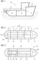
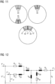
- FIG 1 shows a ship 101 with a first division into zones.
- a first zone 31, a second zone 32, a third zone 33 and a fourth zone 34 are shown.
- Another example is a watertight deck 70.
- FIG 2 shows a ship 101 in a kind of top view, as well as top view, with a second division into zones 31 to 39.
- the zones can also be divided into longitudinal zones 102 and transverse zones 103.
- a power supply system 100 extends across the zones.
- the power supply system has a first DC voltage bus 11 and a second DC voltage bus 12 .
- the DC buses 11 and 12 extend differently across the zones.
- the partitioning in the longitudinal zones can also be omitted. However, this is not shown.
- the representation after 3 10 shows a ship 100 with a third subdivision into zones 31 to 39, with zones 37, 38 and 39 being central zones within the ship and bounded by further zones on the port side and starboard side, respectively are.
- the energy supply system 100 has a first DC voltage bus 11 and a second DC voltage bus 12, the first DC voltage bus 11 being a medium-voltage bus, for example, and the second DC voltage bus 12 being a low-voltage bus.
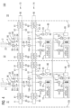
- FIG 4 shows a first circuit diagram for an energy supply system 100.
- the representation has a first zone 31, a second zone 32 and a third zone 33.
- FIG. The zones are marked by zone boundaries 105.
- a first energy source 21 is located in the first zone 31 .
- the first energy source 21 has a diesel engine 1 and a generator 5 .
- a second energy source 22 is located in the second zone 32 .
- the second energy source 22 has a diesel engine 2 and a generator 6 .
- a first DC voltage bus 11 extends into the first zone 31 as well as into the second zone 32 and also into the third zone 33 and forms a ring bus.
- a second DC voltage bus 12 extends both into the first zone 31 and into the second zone 32 and also into the third zone 33 and also forms a ring bus.
- the buses can also not be in the form of ring buses, although this is not shown.
- the first DC voltage bus 11 is located in a first DC voltage level 13 or makes it available.
- the second DC voltage bus 12 is located in a second DC voltage level 14 or makes it available.
- the first direct voltage bus 11 can be divided into sections 61 to 66. The subdivision is achieved by means of MV switching devices 81.
- the first DC voltage bus 11 is therefore at a medium voltage.
- the second DC voltage bus 12 can also be divided into sections 61-66. The subdivision is achieved by means of LV switching devices 80.
- the second DC voltage bus 12 is therefore at a low voltage.
- a three-phase bus (AC bus) 15 can be fed via the second DC voltage bus 12 .
- Batteries 91 are also connected to the second DC voltage bus 12 .
- Motors 85 which have inverters 93 can be operated, as well as further DC consumers 86 are shown.
- a first supply 51, a second supply 52, a third supply 53 and a fourth supply 54 are provided for supplying the direct voltage buses 11 and 12 in each case. These feeds are feeding electrical connections for the DC buses.
- the generator 5 feeds the first section 61 via the first feed 51 , the first feed 51 having a rectifier 95 and a switch 84 .
- the generator 5 feeds the fourth section 64 of the first DC voltage bus 11 via the second feed 52.
- the second feed 52 in the first zone 31 also has a rectifier 96 and a switch 84.
- the third feed 53 has a medium-voltage transformer 105 and a rectifier 97 .
- the third feed 53 feeds the first section 61 of the second DC bus 12 .
- the fourth feed 54 has a switch 84 and a DC/DC converter 104 .
- the fourth feed 54 thus connects a section 64 of the first direct current bus 11 to a section 61 of the second direct current bus 12.
- the generator 6 is connected to the direct current buses 11 and 12 in the same way via the feeds 1 to 4, as described in the first zone 31.
- FIG 5 shows a second circuit diagram for a power supply system 100 is compared to FIG 4 an enlarged section is shown.
- a generator 5 is shown which has only three feeding electrical connections 51, 53 and 54 to the DC buses 11 and 12.
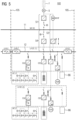
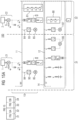
- the representation after 6 shows a third circuit diagram for an energy supply system 100. It shows that ship propulsion motors 106, 107 can be connected as consumers to the first DC voltage bus 11, each of which is provided for driving a propeller 108. Motor 106 is doubly fed via inverters 93 and 94 . Motor 107 is single fed.
- auxiliary drives e.g. compressor drive 207.
- a three-phase network can be generated via an active inverter, e.g. a modular multilevel converter (MMC) with/without a filter 208, which is connected to the DC voltage bus 11.
- MMC modular multilevel converter
- a generator 201 with an associated rectifier is shown.
- a generator 200 with at least two winding systems and two associated rectifiers can be used for powers that cannot be realized for a rectifier.
- these rectifiers can also feed a generator with a winding system (not shown) in parallel.
- the generator 202 spears the first direct voltage bus 11 via a rectifier and the second direct voltage bus 12 via a transformer 205 and a rectifier 206.
- a feed 204 is shown as a shore connection.
- a connection of the DC voltage bus 11 to the DC voltage bus 12 with a DC/DC converter 209 is shown as an embodiment.
- this DC/DC converter is shown as a three-pole 210, three pole.
- this DC bus 12 and 11 also connect a battery 211 and or another DC bus.
- this three-pole can also be in the form of a multi-pole.
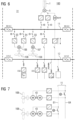
- FIG 7 shows a fourth circuit diagram, two motors each being connected to the propellers 108 via a shaft system 43 for driving purposes.
- the power is supplied via the DC voltage bus 11, but via different sections 61 and 64 of this bus.
- the representation after 8 shows a fifth circuit diagram, in which alternative energy sources are also shown in addition to four energy sources 21 to 24 with diesel.
- a wind turbine 25 can be an energy source.
- a shore connection 26 can be an energy source but also a photovoltaic system 27.
- the representation after 9 shows a generator system 10 with two generators 7 and 8, which are rigidly coupled via a shaft system 43.
- the generator 7 here has a low-voltage winding system and the generator 8 has a medium-voltage winding system.
- a low-voltage direct current bus 12 is fed by means of the generator 7 and a medium-voltage direct current bus 11 is fed by means of the generator 8 .
- the representation after 10 shows a multi-winding system generator 9 which has at least two winding systems, a first winding system for a medium voltage and a second winding system for a low voltage.
- the first DC bus 11 is fed at the medium-voltage level (MV) via a first feeding electrical connection 51 .
- the second winding system is used to feed the second DC bus 12 at the low-voltage level (LV) via a further feeding electrical connection 53 .
- the representation after 11 shows schematically the possible arrangements of windings in the stator of a multi-winding system generator.
- the LV windings can be in sections in adjacent slots 44 and the MV windings in sections in adjacent slots 45.
- the MV windings and the LV windings can be in common slots 46.
- the MV windings and the LV windings can be in slots 24 and 48 alternately.
- the representation after 12 shows an equivalent circuit for a D-axis of a multi-winding system generator.
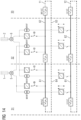
- the representation after 13 shows an eighth circuit diagram for an energy supply system 100, showing how the generator 6 can feed the first DC voltage bus 11 via two different sections 61 and 64 and how the second DC voltage bus 12 can also be fed from this generator 6 via two different sections there as well can.
- the representation after 14 shows how two sections 61 and 62 of the first DC voltage bus 11 in different zones 31 and 32 can be fed by a generator in a zone (generator 5 in zone 31 and generator 6 in zone 32) and how this also applies to the second DC voltage bus 12 .
- the representation after 15 is divided into two partial figures 15A and 15B. Both combine an energy supply system 100, which has four diesel engines 1, 2, 3 and 4 as part of the energy sources 21, 22, 23 and 24 and expresses the fact that the energy supply system can be expanded or changed almost at will according to the requirements of the water-based facility . Because the water-based device is located, for example, on a ship or an oil platform, it is operated entirely or predominantly as an island network.
Description
Die Erfindung betrifft eine wassergebundene Einrichtung, insbesondere eine schwimmende Einrichtung, mit einem Energieversorgungssystem.The invention relates to a water-bound device, in particular a floating device, with an energy supply system.
Schwimmende Einrichtungen sind beispielsweise Schiffe, U-Boote, Ölplattformen und/oder Gasplattformen. Beispiele für Schiffe sind Kreuzfahrtschiffe, Fregatten, Containerschiffe, Flugzeugträger, Eisbrecher etc.. Schwimmende Einrichtungen sind wassergebundene Einrichtungen. Ölplattformen oder Gasplattformen, welche auf dem Meeresgrund stehen, sind Beispiele für wassergebundene Einrichtungen. Neben dem Energieversorgungssystem betrifft die Erfindung auch ein entsprechendes Verfahren zum Betrieb dieses Energieversorgungssystems.Floating facilities are, for example, ships, submarines, oil platforms and/or gas platforms. Examples of ships are cruise ships, frigates, container ships, aircraft carriers, icebreakers, etc. Floating facilities are water-based facilities. Oil rigs or gas rigs standing on the seabed are examples of water-based facilities. In addition to the energy supply system, the invention also relates to a corresponding method for operating this energy supply system.
Ein Energieversorgungssystem für eine wassergebundene Einrichtung bzw. eine schwimmende Einrichtung weist Energiequellen auf. Wird nachfolgend von einer schwimmenden Einrichtung gesprochen, so ist damit auch entsprechend eine wassergebundene Einrichtung gemeint und umgekehrt. Beispiele für Energiequellen sind ein Dieselgenerator, eine Brennstoffzelle, eine Batterie/Akkumulator, ein Schwungrad, etc. Der Diesel des Dieselgenerators ist beispielsweise mit Schwerölschiffsdiesel und/oder LNG betreibbar. Das Energieversorgungssystem ist beispielsweise dafür vorgesehen, einen Antrieb der schwimmenden Einrichtung mit elektrischer Energie zu versorgen oder auch Hilfsbetriebe bzw. weitere Verbraucher, wie Klimaanlage, Beleuchtung, Automatisierungssysteme, etc. Das Energieversorgungssystem ist insbesondere derart ausgestaltbar, dass auch bei Ausfall einer Energiequelle zumindest ein Notbetrieb für die schwimmende Einrichtung ermöglicht werden kann. Die Energieversorgung einer schwimmenden Einrichtung weist insbesondere ein Bordnetz auf. Das Bordnetz (das elektrische Bordnetz) dient der elektrischen Energieversorgung der schwimmenden Einrichtung.A power supply system for a water-based facility or a floating facility has energy sources. If a floating facility is mentioned below, this also means a water-bound facility and vice versa. Examples of energy sources are a diesel generator, a fuel cell, a battery/accumulator, a flywheel, etc. The diesel from the diesel generator can be operated with heavy oil ship diesel and/or LNG, for example. The energy supply system is intended, for example, to supply a drive of the floating facility with electrical energy or also auxiliary systems or other consumers, such as air conditioning, lighting, automation systems, etc. The energy supply system can be configured in particular in such a way that even if one energy source fails, at least emergency operation is possible can be made possible for the floating facility. The power supply for a floating facility has, in particular, an on-board network. The on-board network (the on-board electrical system) serves to supply the floating device with electrical energy.
Ist eine schwimmende Einrichtung beispielsweise dazu befähigt, ihre Position zu halten, so weist diese eine Vielzahl von Antrieben auf. Diese Antriebe weisen insbesondere einen Propeller oder einen Wasserstrahler (Waterjet) auf. Diese Antriebe zum Halten der Position des Schiffes im Wasser und/oder für den Vortrieb des Schiffes im Wasser sind insbesondere unabhängig voneinander betriebsbereit zu halten. Weist diese schwimmende Einrichtung beispielsweise zwei oder mehr Antriebssysteme im Heckbereich auf, wie z.B. zwei POD-Antriebe oder zwei Propeller mit aus dem Schiffsrumpf ragenden Wellen, welche von einem elektrischen Motor und/oder von einem Dieselmotor mit einem Wellengenerator angetrieben sind, so ist es vorteilhaft, wenn diese im Falle eines Fehlers bei einem Antrieb unabhängig voneinander mit elektrischer Energie versorgt werden können.If a floating device is capable of maintaining its position, for example, then it has a large number of drives. These drives have in particular a propeller or a water jet (water jet). These drives for maintaining the position of the ship in the water and/or for propelling the ship in the water are to be kept ready for operation, in particular independently of one another. If this floating device has, for example, two or more drive systems in the stern area, such as two POD drives or two propellers with shafts protruding from the ship's hull, which are driven by an electric motor and/or a diesel engine with a shaft generator, it is advantageous if these can be supplied with electrical energy independently of one another in the event of a fault in a drive.
Aus der
Aus der
Aus der
Aus der
Aus der
In elektrischen Bordnetzen wird die elektrische Energie oft in verschiedenen Spannungsebenen und/oder in verschiedenen Spannungsformen (AC bzw. DC) benötigt. Dazu wird beispielsweise Primärenergie aus einer oder mehreren Verbrennungskraftmaschinen zur Verfügung gestellt und mittels eines oder mehrere Drehstromgeneratoren (Asynchrongenerator bzw. Synchrongcncrator) in elektrische Energie umgewandelt. Der Synchrongenerator ist beispielsweise ein permanenterregter Synchrongenerator. Diese elektrische Energie wird insbesondere auf der höchsten im Bordnetz zur Verfügung stehenden Spannungsebenen (Versorgungsnetz obere Spannungsebene) erzeugt. Um weitere Spannungsebenen zu erzeugen werden zum Beispiel Transformatoren und/oder DC/DC-Wandler eingesetzt. Die Transformatoren haben in der Regel ein hohes Gewicht und Bauvolumen, Verluste in Höhe von ca. 1% und die Eingangs- und Ausgangs-Frequenz sind immer identisch. Beispielsweise wird die gesamte erzeugte Generatorleistung über die obere Spannungsebene eingespeist und auf einen Hautenergiebus verteilt. Der Hauptenergiebus ist in vielen Anlagen bzw. Bordnetzen ein 3 Phasen Wechselstrom Bus (Wechselstrom=AC), wodurch ein AC Netz aufgespannt ist. Die Verteilung der elektrischen Energie erfolgt dabei insbesondere über eine oder mehrere Schalttafeln. In AC Netzen ist die Frequenz eines unteren Netzes gleich der Frequenz des oberen Netzes. Dabei unterscheidet sich das untere Netz vom oberen Netz durch die Spannung, wobei das obere Netz eine höhere Spannung hat als das untere Netz. Die Verwendung eines AC Netzes mit einem AC Energiebus zur Verteilung der elektrischen Energie kann nachteilig sein, wenn in der oberen Spannungsebene die Frequenz variabel ist. Variable Frequenzen sind besondere die Folge von drehzahlvariablen Verbrennungsmaschinen. Um aus einem oberen AC Energiebus eine untere Spannungsebene zu versorgen werden in der Regel mehrere Transformatoren benötigt. Die Energie wird über den oberen AC Hauptenergiebus also über die obere Spannungsebene übertragen. Innerhalb einer Spannungsebene kann die Energie über eine Schaltanlage verteilt werden. Zur Verteilung von AC wird eine AC Schaltanlage verwendet. Die Spannungshöhe des Energiebusses bzw. der Spannungsebene hängen maßgeblich von der installierten Leistung ab. Die verschiedenen Verbraucher werden gespeist und die darunter liegenden Spannungsebenen mit Energie versorgt. Zur Verbindung der unterschiedlichen Spannungsebenen sind in AC Netzen Transformatoren notwendig, wodurch die Spannungsebenen die gleiche Frequenz haben. Das Übersetzungsverhältnis des verwendeten Transformators legt das Verhältnis der Spannungen fest.In on-board electrical systems, the electrical energy is often required at different voltage levels and/or in different voltage forms (AC or DC). For this purpose, for example, primary energy is made available from one or more internal combustion engines and by means of one or more three-phase generators (asynchronous generator or synchronous generator) converted into electrical energy. The synchronous generator is, for example, a permanently excited synchronous generator. This electrical energy is generated in particular at the highest voltage level available in the vehicle electrical system (supply network, upper voltage level). Transformers and/or DC/DC converters, for example, are used to generate additional voltage levels. The transformers usually have a high weight and volume, losses of around 1% and the input and output frequencies are always identical. For example, the entire generator power generated is fed in via the upper voltage level and distributed to a main energy bus. In many systems or vehicle electrical systems, the main energy bus is a 3-phase alternating current bus (alternating current = AC), which creates an AC network. The electrical energy is distributed in particular via one or more control panels. In AC grids, the frequency is a lower grid equal to the frequency of the upper grid. The lower net differs from the upper net in terms of tension, with the upper net having a higher tension than the lower net. The use of an AC network with an AC energy bus for the distribution of electrical energy can be disadvantageous if the frequency is variable in the upper voltage level. Variable frequencies are particularly the result of variable-speed internal combustion engines. In order to supply a lower voltage level from an upper AC power bus, several transformers are usually required. The energy is transmitted via the upper AC main energy bus, i.e. via the upper voltage level. Within a voltage level, the energy can be distributed via a switchgear. AC switchgear is used to distribute AC. The voltage level of the power bus or the voltage level depends largely on the installed power. The various consumers are fed and the underlying voltage levels are supplied with energy. To connect the different voltage levels in AC networks, transformers are required, which means that the voltage levels have the same frequency. The transformation ratio of the transformer used determines the ratio of the voltages.
Da auf der schwimmenden Einrichtung die Verbraucher unterschiedliche Anforderungen an das Energieversorgungssystem stellen und auch abhängig vom Betriebszustand der schwimmenden Einrichtung unterschiedliche Verbraucher Energie vom Energieversorgungssystem beziehen, ist dieses möglichst flexibel auszulegen. Eine Aufgabe der vorliegenden Erfindung ist es demnach, ein flexibles Energieversorgungssystem bzw. ein flexibles Verfahren zum Betrieb eines solchen Energieversorgungssystems bereit zu stellen.Since the consumers on the floating facility have different requirements for the energy supply system and also depending on the operating state of the floating facility, different consumers draw energy from the energy supply system, this should be designed as flexibly as possible. It is therefore an object of the present invention to provide a flexible energy supply system or a flexible method for operating such an energy supply system.
Eine Lösung der Aufgabe gelingt nach Anspruch 1 bzw. 11. Weitere Ausgestaltungen der Erfindung ergeben sich nach den Ansprüchen 2 bis 10 bzw. 12 bis 13.The object is achieved according to
Ein Energieversorgungssystem für eine wassergebundene Einrichtung, sowie insbesondere für eine schwimmende Einrichtung, weist einen ersten Gleichspannungsbus für eine erste Gleichspannung und einen zweiten Gleichspannungsbus für eine zweite Gleichspannung auf. Dies bedeutet, dass der erste Gleichspannungsbus für eine erste Gleichspannungsebene geeignet bzw. vorgesehen ist und der zweite Gleichspannungsbus für eine zweite Gleichspannungsebenen geeignet bzw. vorgesehen ist. Die erste Gleichspannungsebene ist höher als die zweite Gleichspannungsebene. Die erste Gleichspannungsebene entspricht also dem ersten Gleichspannungsbus und die zweite Gleichspannungsebene entspricht dem zweiten Gleichspannungsbus. Beispielsweise unterscheiden sich die Gleichspannungsebenen um einen Faktor zwischen 5 und 50. Es sind also Verhältnisse von z.B. 1:5 bis 1:20 möglich. Entsprechendes ergibt sich bei einer wassergebundenen bzw. schwimmenden Einrichtung, insbesondere ein Schiff, welche ein Energieversorgungssystem in einer der beschriebenen Ausgestaltungen aufweist.An energy supply system for a water-based device, and in particular for a floating device, has a first DC voltage bus for a first DC voltage and a second DC voltage bus for a second DC voltage. This means that the first DC voltage bus is suitable or provided for a first DC voltage level and the second DC voltage bus is suitable or provided for a second DC voltage level. The first DC voltage level is higher than the second DC voltage level. The first direct voltage level thus corresponds to the first direct voltage bus and the second direct voltage level corresponds to the second direct voltage bus. For example, the DC voltage levels differ by a factor of between 5 and 50. Ratios of e.g. 1:5 to 1:20 are possible. The same applies to a water-bound or floating device, in particular a ship, which has an energy supply system in one of the configurations described.
Beispiele für eine wassergebundene Einrichtung sind: ein Schiff (z.B. Kreuzfahrer, Containerschiffe, Feeder-Schiffe, Supportschiffe, Kranschiffe, Tanker, Kampfschiffe, Landungsschiffe, Eisbrecher etc.), eine schwimmende Plattform, eine fest im Meeresgrund verankerte Plattform, etc.Examples of a waterborne facility are: a ship (e.g., crusaders, container ships, feeder ships, support ships, crane ships, tankers, combat ships, landing ships, icebreakers, etc.), a floating platform, a platform anchored to the seabed, etc.
Die schwimmende bzw. wassergebundene Einrichtung und/oder das Energieversorgungssystem weist in einer Ausgestaltung eine erste Zone und eine zweite Zone auf. Auch hier soll, wie bereits obig angemerkt, im weiteren Fortgang unter einer schwimmenden Einrichtung auch eine wassergebundene Einrichtung verstanden werden. Die schwimmende Einrichtung kann auch mehr als zwei Zonen aufweisen. Die Art der Zonen kann unterschiedlich sein. So kann es sich bei einer Zone beispielsweise um eine Feuerzone handeln. Zonen können voneinander durch eine oder mehrere Schotten getrennt sein. Der Art bilden sich Kammern aus, welche beispielsweise dem Schutz vor Feuer und oder dem Schutz vor einem Untergang der schwimmenden bzw. wassergebundenen Einrichtung dienen können. Ein Schott bzw. Schotten kann luftdicht und/oder flüssigkeitsdicht und/oder brandhemmend ausgelegt bzw. ausgeführt sein. In einer schwimmenden Einrichtung wie beispielsweise einem Schiff kann es zum Beispiel zumindest ein Querschott und/oder ein Längsschott und/oder ein wasserdichtes Deck geben. Jedoch bilden sich Zonen bzw. Kammern. Eine Kammer kann eine Zone darstellen wie auch eine Zone eine Kammer darstellen kann. Das Energieversorgungssystem für die schwimmende bzw. wassergebundene Einrichtung weist eine erste Energiequelle und eine zweite Energiequelle auf, wobei die erste Energiequelle in der ersten Zone zur Speisung zumindest eines Gleichspannungsbusses der zumindest zwei Gleichspannungsbusse vorgesehen ist und wobei die zweite Energiequelle in der zweiten Zone zur Speisung zumindest eines Gleichspannungsbusses der zumindest zwei Gleichspannungsbusse vorgesehen ist. Die erste Energiequelle kann also beispielsweise zur Speisung nur des ersten Gleichspannungsbusses vorgesehen sein oder zur Speisung des ersten Gleichspannungsbusses und des zweiten Gleichspannungsbusses vorgesehen sein. Ebenso verhält es sich mit der zweiten Energiequelle welchen beispielsweise zur Speisung nur des ersten Gleichspannungsbusses vorgesehen sein oder zur Speisung des ersten Gleichspannungsbusses und des zweiten Gleichspannungsbusses vorgesehen sein kann. Die Speisung des jeweiligen Gleichspannungsbusses betrifft dabei insbesondere eine direkte Verbindung zu dem Gleichspannungsbus. Unter einer direkten Verbindung ist eine elektrische Verbindung zu verstehen, bei welcher kein weiterer DC-Bus zur Energieverteilung zwischengeschaltet ist. Eine direkte Verbindung kann jedoch beispielsweise einen Stromrichter, einen Transformator, einen Schalter, einen DC/DC Steller aufweisen. Energiequellen des Energieversorgungssystems können beispielsweise folgenden Typs sein: ein Dieselgenerator, ein Gasturbinengenerator, eine Batterie, ein Kondensator, SUPER-Caps, ein Schwungradspeicher, Brennstoffzellen sein.In one embodiment, the floating or water-bound facility and/or the energy supply system has a first zone and a second zone. Here, too, as already noted above, a floating facility should also be understood to mean a water-bound facility. The floating device can also have more than two zones. The type of zones can be different. For example, a zone can be a fire zone. Zones may be separated from each other by one or more bulkheads. The species forms chambers which, for example, provide protection against fire and/or the protection against sinking of the floating or water-bound facility can serve. A bulkhead or bulkheads can be designed or constructed to be airtight and/or liquid-tight and/or fire-retardant. In a floating facility such as a ship, for example, there may be at least one transverse bulkhead and/or longitudinal bulkhead and/or watertight deck. However, zones or chambers form. A chamber can represent a zone, just as a zone can represent a chamber. The energy supply system for the floating or water-based facility has a first energy source and a second energy source, the first energy source being provided in the first zone for feeding at least one DC bus of the at least two DC buses and the second energy source being in the second zone for feeding at least a direct voltage bus of the at least two direct voltage buses is provided. The first energy source can therefore be provided, for example, for feeding only the first DC voltage bus or for feeding the first DC voltage bus and the second DC voltage bus. The same applies to the second energy source, which can be provided, for example, for feeding only the first direct voltage bus or for feeding the first direct voltage bus and the second direct voltage bus. The feeding of the respective DC bus relates in particular to a direct connection to the DC bus. A direct connection is to be understood as an electrical connection in which no further DC bus for power distribution is interposed. However, a direct connection can have, for example, a power converter, a transformer, a switch, a DC/DC controller. Energy sources of the energy supply system can be of the following type, for example: a diesel generator, a gas turbine generator, a battery, a capacitor, SUPER-Caps, a flywheel storage device, fuel cells.
In einer Ausgestaltung des Energieversorgungssystems ist dieses zumindest teilweise zonenabhängig gegliedert. Insbesondere entspricht die Gliederung örtlich der Zonenaufteilung für zumindest zwei Zonen. Zonen der wassergebundenen Einrichtung ergeben sich insbesondere durch eine bauliche Einrichtung wie ein Schott. Eine Gliederung des Energieversorgungssystems ergibt sich insbesondere durch Schalteinrichtungen, welche eine elektrische Verbindung trennen oder herstellen können. Durch derartige Schalteinrichtungen können Abschnitte im Energieversorgungssystem ausgebildet sein.In one configuration of the energy supply system, this is at least partially divided up according to zones. In particular the structure corresponds locally to the zone division for at least two zones. Zones of the water-bound facility result in particular from a structural facility such as a bulkhead. A structure of the energy supply system results in particular from switching devices which can separate or establish an electrical connection. Sections in the energy supply system can be formed by switching devices of this type.
In einer Ausgestaltung des Energieversorgungssystems wird zwischen primären Energiequellen und sekundären Energiequellen unterschieden. Diese Typen von Energiequellen betreffen deren Zuordnung zu einem jeweiligen Bus. Diese Typen von Energiequellen betreffen jegliche Art von Energiequelle, wie z.B. einen Dieselgenerator, eine Batterie, eine Brennstoffzelle, eine Gasturbine mit Generator, SUPER-Caps, Schwungradspeicher, etc.. Primäre Energiequellen sind dem ersten Gleichspannungsbus (DC-Bus) zugeordnet, wobei eine primäre Energiequelle insbesondere der Gewinnung elektrischer Energie für den Hauptantrieb der schwimmenden bzw. wassergebundenen Einrichtung dient. Beispielsweise kann eine oder können mehrere primäre Energiequellen auch der Versorgung eines weiteren, insbesondere nachgeordneten Gleichspannungsbusses (weist eine kleinere DC-Spannung auf als der versorgende DC-Bus) dienen. Diese Zuordnung bedeutet, dass zwischen dieser primären Energiequelle und dem ersten Gleichspannungsbus kein weiterer Gleichspannungsbus zwischengeschaltet ist. Sekundäre Energiequellen sind dem zweiten Gleichspannungsbus (DC-Bus) zugeordnet, wobei eine sekundäre Energiequelle insbesondere der Gewinnung elektrischer Energie für Betriebssysteme der schwimmenden bzw. wassergebundenen Einrichtung dient, welche nicht dem Hauptantrieb der schwimmenden Einrichtung dienen. Auch diese Zuordnung bedeutet, dass zwischen dieser sekundären Energiequelle und dem zweiten Gleichspannungsbus kein weiterer Gleichspannungsbus zwischengeschaltet ist. Es gibt in einer Ausgestaltung auch die Möglichkeit, zumindest eine sekundäre Energiequelle, die dem zweiten Gleichspannungsbus zugeordnet ist, zur Versorgung des ersten Gleichspannungsbusses und insbesondere zur Versorgung der Hauptantriebe zu nutzen. Betriebssysteme der schwimmenden Einrichtung sind beispielsweise (Bordversorgung, Hotelbetrieb, Waffensysteme, etc.). In einer Ausgestaltung des Energieversorgungssystems sind sekundäre Energiequellen derart gewählt, dass diese ggf. schneller auf Lastschwankungen reagieren können. Die Last ist beispielsweise zumindest ein Antriebsmotor zum Antrieb der schwimmenden Einrichtung und oder weitere elektrische Verbraucher der schwimmenden Einrichtung für beispielsweise Pumpen, Kompressoren, Klimaanlagen, Seilwinden, Bordelektronik, etc. Bei einem Kreuzfahrtschiff werden elektrische Verbraucher für beispielsweise die Klimaanlage, die Küchen, die Wäscherei, die Beleuchtung, etc. auch als Hotellast bezeichnet.In one embodiment of the energy supply system, a distinction is made between primary energy sources and secondary energy sources. These types of energy sources relate to their assignment to a respective bus. These types of energy sources relate to any type of energy source, such as a diesel generator, a battery, a fuel cell, a gas turbine with generator, SUPER-Caps, flywheel storage, etc.. Primary energy sources are assigned to the first direct current bus (DC bus), with a primary energy source is used in particular to generate electrical energy for the main drive of the floating or water-bound facility. For example, one or more primary energy sources can also be used to supply a further, in particular downstream, DC voltage bus (has a lower DC voltage than the supplying DC bus). This assignment means that no further direct voltage bus is interposed between this primary energy source and the first direct voltage bus. Secondary energy sources are assigned to the second direct voltage bus (DC bus), with a secondary energy source serving in particular to generate electrical energy for operating systems of the floating or water-bound facility which are not used for the main drive of the floating facility. This assignment also means that no further direct voltage bus is interposed between this secondary energy source and the second direct voltage bus. In one configuration, there is also the possibility of using at least one secondary energy source, which is assigned to the second DC voltage bus, to supply the first DC voltage bus and in particular to supply the main drives. Operating systems of the floating facility are, for example (on-board supply, hotel operations, weapon systems, etc.). In one embodiment of the energy supply system, secondary energy sources are selected in such a way that they can react more quickly to load fluctuations, if necessary. The load is, for example, at least one drive motor for driving the floating facility and/or other electrical consumers of the floating facility for pumps, compressors, air conditioning, cable winches, on-board electronics, etc., for example. On a cruise ship, electrical consumers are used for the air conditioning, the kitchens, the laundry, for example , the lighting, etc. also referred to as hotel load.
Das Energieversorgungsystem kann mehrere Energiequellen gleichen Typs aufweisen. In einer Ausgestaltung des Energieversorgungssystems können Energiequellen unterschiedlichen Typs in unterschiedlichen Zonen sein. Dadurch kann die Versorgungssicherheit innerhalb der schwimmenden Einrichtung beispielsweise in Notfällen und/oder in einem Fehlerfall erhöht werden. In einer weiteren Ausgestaltung können Energiequellen unterschiedlichen Typs in der gleichen Zone sein.The energy supply system can have several energy sources of the same type. In one configuration of the energy supply system, energy sources of different types can be in different zones. As a result, the security of supply within the floating facility can be increased, for example in emergencies and/or in the event of a fault. In a further embodiment, energy sources of different types can be in the same zone.
In einer Ausgestaltung des Energieversorgungssystems wird die Zwischenkreisspannung an der kleinsten Last, d.h. der kleinsten Leistung bemessen, so dass hierfür ein Inverter eingesetzt werden kann. Bei weiteren größeren Lasten wird solange ein einzelner Inverter verwendet solange dieser verfügbar ist. Für weitere größere Lasten, die für einen Inverter mit der gewählten Spannung zu groß sind werden parallele Inverter oder Motoren mit mehreren Wicklungssystemen verwendet. Durch diese Vorgehensweise können Mittelspannuns- Gleichspannungssysteme kostenoptimiert realisiert werden.In one embodiment of the energy supply system, the intermediate circuit voltage is measured at the lowest load, i.e. the lowest power, so that an inverter can be used for this. For other larger loads, a single inverter is used as long as it is available. For other larger loads that are too large for an inverter with the selected voltage, parallel inverters or motors with multiple winding systems are used. With this procedure, medium-voltage direct voltage systems can be implemented in a cost-optimized manner.
Zum Bespiel wird die Zwischenkreisspanung bei einer Thrusterlast von 3,5 MW auf 4,5 kV Gleichspannung (3,3 kV Drehspannung) festgelegt. Die 3,5 MW ist die kleinste Last, die am Mittelspapnnungs-Gleichspannungssystem angeschlossen ist. Eine weitere Last mit 12 MW wird ebenfalls mit 3,3 kV Drehspannung, und damit mit 4,5 kV Gleichspannung betrieben. Diese Last wird mit zwei parallelen Umrichtern oder mit einer Maschine mit zwei Wicklungssystemen betrieben. Auch zwei Maschinen auf einer Welle sind möglich.For example, the intermediate circuit voltage is set to 4.5 kV DC voltage (3.3 kV three-phase voltage) for a thruster load of 3.5 MW. The 3.5 MW is the smallest load connected to the medium voltage DC system. One another load with 12 MW is also operated with 3.3 kV three-phase voltage, and thus with 4.5 kV DC voltage. This load is operated with two parallel converters or with a machine with two winding systems. Two machines on one shaft are also possible.
Mit dem Design Ziel den Mittelspannungs-Gleichspannungsbus im Spannungsbereich 3,2 kV bis 6 kV zu halten werden ein kostenoptimales System sichergestellt.With the design goal of keeping the medium-voltage DC bus in the voltage range of 3.2 kV to 6 kV, a cost-optimal system is ensured.
Größere Leistungen werden durch Parallelschaltung und/oder durch Mehrwicklungsmaschienen realisiert.Larger outputs are realized by parallel connection and/or by multi-winding machines.
Die reduzierte Mittelspannungs-Gleichspannungsfestlegung reduziert auch das Bauvolumen und die Kosten für die Halbleiterschalter zwischen den Zonen als auch die Kosten für den Kurzschlussschutz der InverterThe reduced medium-voltage DC specification also reduces the bulk and cost of the solid-state switches between zones, as well as the cost of short-circuit protection for the inverters
In gleicher Weise kann auch bei den Gleichrichtern auf der Einspeiseseite vorgegangen werden.You can proceed in the same way with the rectifiers on the feed side.
Durch die Verwendung eines ersten Gleichspannungsbusses und eines zweiten Gleichspannungsbusses in der schwimmenden Einrichtung kann elektrische Energie in einfacher Weise ohne unnötige Verluste von einem Bus in den anderen Bus übertragen werden. Dies ist insbesondere in einem Fehlerfall vorteilhaft bei dem eine oder mehrere Energiequellen für den ersten Bus ausfallen. Erfolgte eine Verknüpfung von Energieebenen über eine AC Verbindung so kann dies insbesondere in einem Fehlerfall zu höheren Verlusten führen. In DC Netzen wird die Energie erst gleichgerichtet um auf der oberen DC Spannung verteilt zu werden (Umwandlung 1). Anschließend muss aus der DC Spannung mittels eines Wechselrichters eine AC Spannung erzeugt werden (Umwandlung 2). Der Wechselrichter muss die gleichen Funktionen wie ein Generator erfüllen (Selektivität, und Frequenzführung in der unteren Spannungsebene) Zur Anpassung der Spannung ist ein Transformator erforderlich (Umwandlung 3). Diese dreifache Umwandlung ist mit Verlusten in Höhe ca. 3-3,5% verbunden. Die Kosten für die Komponenten und die Gewichte sind sehr hoch. Die eingesetzten Wechselrichter sind empfindlich gegenüber harmonischen der unteren Spannungsebene. Das Aufschalten von Motoren und nicht linearen Lasten auf die eingesetzten Wechselrichter ist auch problematisch und limitiert. Mithilfe des vorgeschlagenen Energieversorgungssystems, welches einen ersten Gleichspannungsbus und einen zweiten Gleichspannungsbus aufweist, können Verluste reduziert werden.By using a first DC voltage bus and a second DC voltage bus in the floating device, electrical energy can be transmitted from one bus to the other bus in a simple manner without unnecessary losses. This is particularly advantageous in the event of a fault in which one or more energy sources for the first bus fail. If energy levels are linked via an AC connection, this can lead to higher losses, especially in the event of a fault. In DC networks, the energy is first rectified in order to be distributed on the upper DC voltage (conversion 1). An AC voltage must then be generated from the DC voltage using an inverter (conversion 2). The inverter must fulfill the same functions as a generator (selectivity and frequency control in the lower voltage level). A transformer is required to adjust the voltage (conversion 3). This triple conversion comes with losses about 3-3.5% connected. The cost of the components and the weights are very high. The inverters used are sensitive to harmonics of the lower voltage level. The connection of motors and non-linear loads to the inverters used is also problematic and limited. Losses can be reduced with the aid of the proposed energy supply system, which has a first DC voltage bus and a second DC voltage bus.
In einer Ausgestaltung des Energieversorgungssystems weist dieses neben der ersten Energiequelle und der zweiten Energiequelle auch eine dritte Energiequelle auf. Die erste Energiequelle und die zweite Energiequelle sind beispielsweise primäre Energiequellen und die dritte Energiequelle ist eine sekundäre Energiequelle. Die dritte Energiequelle kann beispielsweise zum Peakshaving und/oder Spinning Reserve verwendet werden. Dies bedeutet, dass Spitzen im Energieverbrauch der schwimmenden Einrichtung, welche nicht rasch von der primären Energiequelle gedeckt werden können durch die sekundäre Energiequelle gedeckt werden und/oder es kann Energie zur Verfügung gestellt werden falls eine Energiequelle ausfälltIn one configuration of the energy supply system, this also has a third energy source in addition to the first energy source and the second energy source. For example, the first energy source and the second energy source are primary energy sources, and the third energy source is a secondary energy source. The third energy source can be used for peak shaving and/or spinning reserve, for example. This means that peaks in the energy consumption of the floating facility, which cannot be quickly met by the primary energy source, can be met by the secondary energy source and/or energy can be made available if an energy source fails
In einer Ausgestaltung des Energieversorgungssystems weist dieses einen Mittelspannungs-Gleichspannungsbus, mit einer Gleichspannung mit 3 kV bis 18 kV, auf der als Ring Bus ausgeführt ist und einen Niederspannuns-Gleichspannungsbus, mit einer Gleichspannung mit 0,4 kV bis 1,5 kV, auf der als Ring Bus ausgeführt ist.In one embodiment of the energy supply system, this has a medium-voltage DC bus with a DC voltage of 3 kV to 18 kV, which is designed as a ring bus, and a low-voltage DC bus with a DC voltage of 0.4 kV to 1.5 kV designed as a ring bus.
In einer Ausgestaltung des Energieversorgungssystems kann als Energiebus, insbesondere als weiterer Hauptenergiebus oder auch als Ersatz für den DC Bus, zusätzlich zu einem DC Bus auch ein Dreiphasenwechselstrombus (AC Bus) verwendet werden. Auch auf einer Niederspannungsebene kann ein DC Verteilsystem (DC Bus) und/oder ein AC Verteilsystem (AC Bus) verwendet werden.In one embodiment of the energy supply system, a three-phase alternating current bus (AC bus) can also be used as an energy bus, in particular as a further main energy bus or as a replacement for the DC bus, in addition to a DC bus. A DC distribution system (DC bus) and/or an AC distribution system (AC bus) can also be used at a low-voltage level.
Ein Energieversorgungssystem für eine wassergebundene Einrichtung, insbesondere eine schwimmende Einrichtung, ist also auch mit einem ersten Gleichspannungsbus für eine erste Gleichspannung und mit einem zweiten Gleichspannungsbus für eine zweite Gleichspannung ausführbar, wobei das Energieversorgungssystem eine erste Energiequelle aufweist, wobei die erste Energiequelle ein Generatorsystem aufweist, welches ein erstes Wicklungssystem zur Speisung des ersten Gleichspannungsbusses aufweist und welches ein zweites Wicklungssystem zur Speisung des zweiten Gleichspannungsbusses aufweist. So können mit einem Generatorsystem verschiedene Spannungsebenen gespeist werden. Weist das Energieversorgungssystem weitere Energiequellen auf, so können auch diese ein derartiges Generatorsystem aufweisen.An energy supply system for a water-bound facility, in particular a floating facility, can also be designed with a first DC voltage bus for a first DC voltage and with a second DC voltage bus for a second DC voltage, the energy supply system having a first energy source, the first energy source having a generator system, which has a first winding system for feeding the first DC voltage bus and which has a second winding system for feeding the second DC voltage bus. Different voltage levels can be fed with one generator system. If the energy supply system has other energy sources, these can also have such a generator system.
In einer Ausgestaltung des Energieversorgungssystem, wobei hier, wie auch bis hier und im Folgenden alle beschriebenen Energieversorgungssysteme gemeint sind, ist das erste Wicklungssystem für eine erste Spannung ausgelegt und das zweite Wicklungssystem für eine zweite Spannung ausgelegt, wobei die erste Spannung größer ist als die zweite Spannung. Das Generatorsystem weist beispielsweise nur einen Generator auf oder z.B. zwei Generatoren. Der Generator ist insbesondere ein Synchrongenerator. Auch Asynchrongeneratoren und/oder PEM-Generatoren können zum Einsatz kommen. Weist der Generator ein Niederspannungs-Wicklungssystem und ein MittelspannungsWicklungssystem auf, so hat dieser insbesondere ein großes xd". In einer Ausführung des Generators kann dieser ein gro-ßes xd" aufweisen. Hierdurch wird der Kurzschlussstrom-Beitrag des Generators reduziert und eine einfachere Auslegung eines Kurzschlussfesten Gleichrichters ermöglicht. Dieser reduzierte Kurzschlussstrom reduziert auch die mechanische Beanspruchung des Wellenstranges im Kurzschlussfall. Insbesondere die kurzschlussfeste Auslegung des Gleichrichters ermöglicht einen einfachen Aufbau des Energieversorgungssystems da keine zusätzlichen Kurzschluss-Schutz Elemente benötigt werden und damit eine direkte Verbindung ohne Trennorgane zwischen Generator und Gleichrichter möglich ist.In one configuration of the energy supply system, which means all energy supply systems described here, as well as up to here and in the following, the first winding system is designed for a first voltage and the second winding system is designed for a second voltage, with the first voltage being greater than the second Tension. The generator system has, for example, only one generator or, for example, two generators. The generator is in particular a synchronous generator. Asynchronous generators and/or PEM generators can also be used. If the generator has a low-voltage winding system and a medium-voltage winding system, it has a large xd". In one embodiment of the generator, it can have a large xd". As a result, the short-circuit current contribution of the generator is reduced and a simpler design of a short-circuit-proof rectifier is made possible. This reduced short-circuit current also reduces the mechanical stress on the shaft assembly in the event of a short-circuit. In particular, the short-circuit-proof design of the rectifier allows for a simple structure of the energy supply system, since no additional short-circuit protection elements are required and a direct connection without isolating elements between the generator and rectifier is therefore possible.
Dieses ist insbesondere auf der Mittelspannungseben von Vorteil, da Trenn- oder Schutzorgane, wie z.B. Leistungschalter oder Sicherungen, viel Platz benötigen, einen deutlichen Kostenfaktor haben oder zum Teil auch nicht verfügbar sind. Der dreiphasige MiLtelspannungsanschluss des Generators kann beispielsweise an einen Diodengleichrichter oder an einen geregelten Gleichrichter angeschlossen sein und damit den Mittelspannungs-Gleichstrombus zu speisen. Dies gilt in vergleichbarer Weise auch für den dreiphasigen Niederspannungsanschluss für den Niederspannungs-Gleichstrombus. Der Stromrichter für den Niederspannungs- Gleichstrombus kann insbesondere auch ein Active Front End (AFE) sein. Dieser weist insbesondere einen Vier Quadranten Betrieb auf. Dadurch ist es beispielsweise möglich elektrische Energie aus Batterien in den Niederspannungs-Gleichstrombus zu speisen von dort über das Active Front End in den Mittelspannungs-Gleichstrombus. Der Aktive Front End ist ein Aktiver Gleichrichter der Energiefluss in beide Richtungen ermöglicht.This is particularly advantageous at the medium-voltage level, since isolating or protective devices, such as circuit breakers or fuses, require a lot of space, have a significant cost factor or are sometimes not available. The three-phase medium-voltage connection of the generator can be connected, for example, to a diode rectifier or to a regulated rectifier and thus to feed the medium-voltage direct current bus. This also applies in a comparable way to the three-phase low-voltage connection for the low-voltage direct current bus. The power converter for the low-voltage direct current bus can in particular also be an active front end (AFE). In particular, this has a four-quadrant operation. This makes it possible, for example, to feed electrical energy from batteries into the low-voltage direct current bus from there via the Active Front End into the medium-voltage direct current bus. The Active Front End is an active rectifier that allows energy to flow in both directions.
In einer Ausgestaltung des Energieversorgungssystems ist das erste Wicklungssystem elektrisch mit dem ersten Gleichspannungsbus zu dessen trafolosen Speisung verbunden. Durch den Wegfall eines Trafos lässt sich Gewicht, Volumen und/oder Kosten sparen.In one configuration of the energy supply system, the first winding system is electrically connected to the first DC voltage bus in order to feed it without a transformer. By eliminating a transformer, weight, volume and/or costs can be saved.
In einer Ausgestaltung des Energieversorgungssystems ist das zweite Wicklungssystem elektrisch mit dem zweiten Gleichspannungsbus zu dessen trafolosen Speisung verbunden. Auch hier wird durch den Wegfall des Trafos Gewicht, Volumen und/oder Kosten gespart.In one configuration of the energy supply system, the second winding system is electrically connected to the second DC voltage bus in order to feed it without a transformer. Here, too, weight, volume and/or costs are saved by eliminating the transformer.
In einer Ausgestaltung des Energieversorgungssystems weist das Generatorsystem einen ersten Generator mit dem ersten Wicklungssystem und einen zweiten Generator mit dem zweiten Wicklungssystem aufweist, wobei der erste Generator und der zweite Generator mittels eines gemeinsamen Wellensystems antreibbar sind. Der erste Generator und der zweite Generator sind insbesondere steif, also starr gekoppelt. Durch die Verwendung zweier Generatoren für die zwei Wicklungssysteme lässt sich die Konstruktion der Generatoren einfach halten. In einer Ausgestaltung des Energieversorgungssystems ist das Generatorsystem ein Multiwicklungssystemgenerator, wobei der Stator des Multiwicklungssystemgenerators das erste Wicklungssystem und das zweite Wicklungssystem oder weitere Wicklungssystem aufweist. Derart ist ein kompaktes Generatorsystem ausbildbar.In one configuration of the energy supply system, the generator system has a first generator with the first winding system and a second generator with the second winding system, the first generator and the second generator being drivable by means of a common shaft system. The first generator and the second generator are, in particular, rigidly, ie rigidly, coupled. By using two generators for the two winding systems, the construction of the generators can be kept simple. In one configuration of the energy supply system, the generator system is a multi-winding system generator, with the stator of the multi-winding system generator having the first winding system and the second winding system or further winding system. A compact generator system can be formed in this way.
In einer Ausgestaltung des Energieversorgungssystems weist der Multiwicklungssystemgenerator Nuten auf, welche das erste Wicklungssystem und das zweite Wicklungssystem betreffen. Dadurch kann ein kompakter Aufbau realisiert werden.In one configuration of the energy supply system, the multi-winding system generator has slots which relate to the first winding system and the second winding system. A compact structure can thereby be realized.
In einer Ausgestaltung können bei dem Generator die beiden Wicklungssysteme so in den Nuten angeordnet sein, dass eine möglichst gute Entkopplung erreicht wird, um eine Beeinflussung der Wicklungssysteme zu vermeiden. Eine ausreichende Entkopplung wird erreicht, wenn die unterschiedlichen Wicklungssystem in unterschiedlichen Nuten eingebracht sind.In one configuration, the two winding systems in the generator can be arranged in the slots in such a way that the best possible decoupling is achieved in order to avoid influencing the winding systems. Sufficient decoupling is achieved when the different winding systems are placed in different slots.
In einer Ausgestaltung des Energieversorgungssystems weist die wassergebundene Einrichtung, wie insbesondere die schwimmende Einrichtung, eine ersten Zone auch, eine zweite Zone auf , und eine zweite Energiequelle auf, wobei die erste Energiequelle in der ersten Zone zur Speisung zumindest eines Gleichspannungsbusses der zumindest zwei Gleichspannungsbusse vorgesehen ist und wobei die zweite Energiequelle in der zweiten Zone zur Speisung zumindest eines Gleichspannungsbusses der zumindest zwei Gleichspannungsbusse vorgesehen ist. So kann die Sicherheit der Versorgung der Gleichspannungsbusse mit elektrischer Energie verbessert werden.In one configuration of the energy supply system, the water-based device, such as in particular the floating device, also has a first zone, a second zone, and a second energy source, with the first energy source being provided in the first zone for feeding at least one DC voltage bus of the at least two DC voltage buses and wherein the second energy source is provided in the second zone for feeding at least one DC voltage bus of the at least two DC voltage buses. In this way, the reliability of the supply of electrical energy to the DC voltage buses can be improved.
Ein Energieversorgungssystem für eine wassergebundene Einrichtung, insbesondere eine schwimmende Einrichtung, ist auch mit einem ersten Gleichspannungsbus für eine erste Gleichspannung und mit einem zweiten Gleichspannungsbus für eine zweite Gleichspannung ausführbar, wobei eine erste Energiequelle zumindest drei speisende elektrische Verbindungen zu den Gleichspannungsbussen aufweist, wobei zumindest einer der Gleichspannungsbusse Abschnitte aufweist. Auch damit kann die Versorgungssicherheit es Energieversorgungssystems verbessert werden.An energy supply system for a water-based device, in particular a floating device, can also be designed with a first direct voltage bus for a first direct voltage and with a second direct voltage bus for a second direct voltage, with a first energy source has at least three feeding electrical connections to the DC voltage buses, wherein at least one of the DC voltage buses has sections. The security of supply of the energy supply system can also be improved in this way.
In einer Ausgestaltung des Energieversorgungssystems speist eine erste speisende Verbindung der zumindest drei speisenden elektrischen Verbindungen einen ersten Abschnitt und eine zweite speisende Verbindung der zumindest drei speisenden elektrischen Verbindungen speist einen zweiten Abschnitt des gleichen Gleichspannungsbusses, wobei eine dritte speisende Verbindung der zumindest drei speisenden elektrischen Verbindungen einen Abschnitt des weiteren Gleichspannungsbusses speist. So kann die Speisung mit elektrischer Energie über verschiedene Gleichspannungsbusse verteilt werden.In one configuration of the energy supply system, a first feeding connection of the at least three feeding electrical connections feeds a first section and a second feeding connection of the at least three feeding electrical connections feeds a second section of the same DC voltage bus, with a third feeding connection of the at least three feeding electrical connections feeding one Section of the other DC bus feeds. In this way, the supply of electrical energy can be distributed over various DC voltage buses.
In einer Ausgestaltung des Energieversorgungssystems wiest dieses eine vierte speisende Verbindung der ersten Energiequelle, wobei zwei der zumindest vier speisenden Verbindungen zur Speisung des ersten Gleichspannungsbusses in unterschiedlichen Abschnitten des ersten Gleichspannungsbusses vorgesehen sind und wobei zwei weitere der zumindest vier speisenden Verbindungen zur Speisung des zweiten Gleichspannungsbusses in unterschiedlichen Abschnitten des zweiten Gleichspannungsbusses vorgesehen sind. Dies erhöht die Betriebssicherheit der wassergebundenen Einrichtung.In one configuration of the energy supply system, this has a fourth feeding connection of the first energy source, with two of the at least four feeding connections for feeding the first DC voltage bus being provided in different sections of the first DC voltage bus and with two more of the at least four feeding connections for feeding the second DC voltage bus in different sections of the second DC voltage bus are provided. This increases the operational reliability of the water-bound facility.
Ein Energieversorgungssystem für eine wassergebundene Einrichtung, insbesondere eine schwimmende Einrichtung, ist auch mit einem ersten Gleichspannungsbus für eine erste Gleichspannung und mit einem zweiten Gleichspannungsbus für eine zweite Gleichspannung ausführbar, wobei eine erste Energiequelle zumindest zwei speisende elektrische Verbindungen zu den Gleichspannungsbussen aufweist, wobei zumindest einer der Gleichspannungsbusse Abschnitte aufweist. Auch damit kann die Versorgungssicherheit es Energieversorgungssystems verbessert werden.An energy supply system for a water-based facility, in particular a floating facility, can also be designed with a first DC voltage bus for a first DC voltage and with a second DC voltage bus for a second DC voltage, with a first energy source having at least two feeding electrical connections to the DC voltage buses, with at least one the DC buses has sections. The security of supply of the energy supply system can also be improved in this way.
In einer Ausgestaltung des Energieversorgungssystems speist eine erste speisende Verbindung der zumindest zwei speisenden elektrischen Verbindungen einen ersten Abschnitt und eine zweite speisende Verbindung der zumindest zwei speisenden elektrischen Verbindungen speist einen zweiten Abschnitt des gleichen Gleichspannungsbusses oder die zweite speisende Verbindung der zumindest zwei speisenden elektrischen Verbindungen speist einen Abschnitt des weiteren Gleichspannungsbusses. So kann die Speisung mit elektrischer Energie über verschiedene Gleichspannungsbusse verteilt werden.In one configuration of the energy supply system, a first feeding connection of the at least two feeding electrical connections feeds a first section and a second feeding connection of the at least two feeding electrical connections feeds a second section of the same DC voltage bus or the second feeding connection of the at least two feeding electrical connections feeds one Section of the further DC voltage bus. In this way, the supply of electrical energy can be distributed over various DC voltage buses.
In einer Ausgestaltung des Energieversorgungssystems weist dieses eine dritte und vierte speisende Verbindung der ersten Energiequelle, wobei zwei der zumindest vier speisenden Verbindungen zur Speisung des ersten Gleichspannungsbusses in unterschiedlichen Abschnitten des ersten Gleichspannungsbusses vorgesehen sind und wobei zwei weitere der vier speisenden Verbindungen zur Speisung des zweiten Gleichspannungsbusses in unterschiedlichen Abschnitten des zweiten Gleichspannungsbusses vorgesehen sind. Dies erhöht die Betriebssicherheit der wassergebundenen Einrichtung.In one configuration of the energy supply system, this has a third and fourth feeding connection of the first energy source, with two of the at least four feeding connections for feeding the first DC voltage bus being provided in different sections of the first DC voltage bus and with two more of the four feeding connections for feeding the second DC voltage bus are provided in different sections of the second DC voltage bus. This increases the operational reliability of the water-bound facility.
In einer Ausgestaltung des Energieversorgungssystems speist eine erste speisende Verbindung der zumindest zwei speisenden elektrischen Verbindungen einen ersten Abschnitt und eine zweite speisende Verbindung der zumindest zwei speisenden elektrischen Verbindungen speist einen zweiten Abschnitt des gleichen Gleichspannungsbusses, wobei eine dritte speisende Verbindung einen Abschnitt des weiteren Gleichspannungsbusses speist. So kann die Speisung mit elektrischer Energie über verschiedene Gleichspannungsbusse verteilt werden.In one configuration of the energy supply system, a first feeding connection of the at least two feeding electrical connections feeds a first section and a second feeding connection of the at least two feeding electrical connections feeds a second section of the same direct voltage bus, with a third feeding connection feeding a section of the further direct voltage bus. In this way, the supply of electrical energy can be distributed over various DC voltage buses.
In einer Ausgestaltung des Energieversorgungssystems weist die wassergebundene Einrichtung eine erste Zone und eine zweite Zone auf, wobei sich der erste Gleichspannungsbus und/oder der zweite Gleichspannungsbus über die erste Zone und/oder die zweite Zone erstreckt, wobei die erste Energiequelle zur Speisung von Abschnitten des ersten Gleichspannungsbusses und/oder des zweiten Gleichspannungsbusses in unterschiedlichen Zonen vorgesehen ist. Dadurch kann die Redundanz für die Versorgung der Gleichspannungsbusse mit elektrischer Energie erhöht werden.In one configuration of the energy supply system, the water-based device has a first zone and a second zone, the first DC voltage bus and/or the second DC voltage bus extending across the first zone and/or the second zone, the first energy source is provided for feeding sections of the first direct voltage bus and/or the second direct voltage bus in different zones. As a result, the redundancy for the supply of electrical energy to the DC buses can be increased.
In einer Ausgestaltung des Energieversorgungssystems weist dieses eine zweite Energiequelle auf, wobei die erste Energiequelle in der ersten Zone zur Speisung zumindest eines Gleichspannungsbusses der zumindest zwei Gleichspannungsbusse vorgesehen ist und wobei die zweite Energiequelle in der zweiten Zone zur Speisung zumindest eines Gleichspannungsbusses der zumindest zwei Gleichspannungsbusse vorgesehen ist. So können beide Gleichspannungsbusse mit elektrischer Energie versorgt werden, auch wenn nur eine Energiequelle aktiv ist.In one configuration of the energy supply system, it has a second energy source, the first energy source being provided in the first zone for feeding at least one DC voltage bus of the at least two DC voltage buses, and the second energy source being provided in the second zone for feeding at least one DC voltage bus of the at least two DC voltage buses is. In this way, both DC voltage buses can be supplied with electrical energy, even if only one energy source is active.
In einer Ausgestaltung des Energieversorgungssystems weist ein Abschnitt des ersten Gleichspannungsbusses sowohl eine speisende Verbindung zur ersten Energiequelle als auch eine weitere speisende elektrische Verbindung zur zweiten Energiequelle auf. Auch dadurch kann die Flexibilität des Systems verbessert werden.In one configuration of the energy supply system, a section of the first DC voltage bus has both a feeding connection to the first energy source and a further feeding electrical connection to the second energy source. This can also improve the flexibility of the system.
In einer Ausgestaltung des Energieversorgungssystems weist ein Abschnitt des zweiten Gleichspannungsbusses sowohl eine speisende Verbindung zur ersten Energiequelle als auch eine weitere speisende elektrische Verbindung zur zweiten Energiequelle auf. Speisende Verbindungen können hier aber auch im Allgemeinen einen Schalter aufweisen, um die speisende Verbindung (die speisende elektrische Verbindung) flexibel aktivieren bzw. deaktivieren zu können.In one configuration of the energy supply system, a section of the second DC voltage bus has both a feeding connection to the first energy source and a further feeding electrical connection to the second energy source. However, feeding connections can also generally have a switch here in order to be able to flexibly activate or deactivate the feeding connection (the feeding electrical connection).
In einer Ausgestaltung des Energieversorgungssystems ist zumindest einer der Gleichspannungsbusse als ein Ringbus ausbildbar bzw. ausgebildet. Der Ringbus ist durch Schalter auftrennbar. Insbesondere kann ein Ringbus in zwei kleinere Busse unterteilt werden. Die kleineren Busse können ihrerseits durch Zusatz Elemente in Ringbusse verwandelt werden. Durch die Möglichkeit der Auftrennung des Ringbusses kann flexibel auf Fehler reagiert werden.In one configuration of the energy supply system, at least one of the DC buses can be designed or designed as a ring bus. The ring bus can be separated by switches. In particular, a ring bus can be divided into two smaller buses. The smaller buses can in turn be transformed into ring buses with additional elements. Through the possibility of splitting the ring bus means that errors can be reacted to flexibly.
In einer Ausgestaltung des Energieversorgungssystems sind die Schalter zur Auftrennung des Busses und/oder Ringbusses als ultraschnelle Schaltelemente ausgeführt und insbesondere als Halbleiter- Schaltorgane oder Hybrid- Schaltorgane, die eine Auslösezeit im Bereich von 1 us bis 150 us aufweisen. Hybrid-Schaltorgane weisen mechanische und Halbleiter und/oder Elektronische Elemente aus. Die schnelle Auslösung reduziert den auftretenden Kurzschlussstrom und verhindert eine negative Auswirkung des Fehlers auf die benachbarte Zone. Dieses verhindert weitere Ausfälle von benachbarten Zonen.In one embodiment of the energy supply system, the switches for separating the bus and/or ring bus are designed as ultra-fast switching elements and in particular as semiconductor switching elements or hybrid switching elements that have a tripping time in the range from 1 μs to 150 μs. Hybrid switching elements have mechanical and semiconductor and/or electronic elements. Fast tripping reduces the short-circuit current that occurs and prevents the fault from having a negative impact on the adjacent zone. This prevents further failures of neighboring zones.
Erfindungsgemäß ist der erste Gleichspannungsbus des Energieversorgungssystems für eine erste Gleichspannung vorgesehen und der zweite Gleichspannungsbus des Energieversorgungssystems für eine zweite Gleichspannung vorgesehen, wobei die erste Gleichspannung größer ist als die zweite Gleichspannung. Insbesondere ist die kleinere Spannung eine Niederspannung (LV) und die höhere Spannung eine Mittelspannung (MV). Die Niederspannung ist insbesondere zwischen 400V und 1000V. Zukünftig also realisiert sind auch Niederspannungssysteme bis zu einer Spannung von 1500V zu erwarten. Die Mittelspannung ist größer 1000V bzw. 1500V, insbesondere zwischen 10kV und 20kV oder zwischen 5kV und 20kV. Als Werte für die Mittelspannung bieten sich beispielsweise folgende an: 5kV, 6kV, 12kV und 18kV. Insbesondere bieten die unterschiedlichen Spannungsebenen der Gleichspannungsbusse auch eine kostenoptimale Zuordnung (insbesondere wegen der Kosten der Leistungselektronik) der Verbraucher, wobei hier die Verbraucher kleinerer Leistung der kleineren Spannung zugeordnet werden. Unter Zuordnung ist die elektrische Anbindung des Verbrauchers an den Gleichspannungsbus zu verstehen.According to the invention, the first direct voltage bus of the energy supply system is provided for a first direct voltage and the second direct voltage bus of the energy supply system is provided for a second direct voltage, the first direct voltage being greater than the second direct voltage. In particular, the smaller voltage is a low voltage (LV) and the higher voltage is a medium voltage (MV). The low voltage is in particular between 400V and 1000V. In the future, therefore, low-voltage systems up to a voltage of 1500V can also be expected. The medium voltage is greater than 1000V or 1500V, in particular between 10kV and 20kV or between 5kV and 20kV. For example, the following values are suitable for medium voltage: 5kV, 6kV, 12kV and 18kV. In particular, the different voltage levels of the DC voltage buses also offer a cost-optimal assignment (particularly because of the costs of the power electronics) of the consumers, with the consumers with lower power being assigned the lower voltage here. Allocation means the electrical connection of the load to the DC voltage bus.
In einer Ausgestaltung des Energieversorgungssystems ist der erste Gleichspannungsbus mit dem zweiten Gleichspannungsbus beispielsweise über zumindest einer der folgenden Kopplungen verbunden:
- o DC/DC-Wandler
- o Wechselrichter - Transformator - Gleichrichter
- o DC/DC converter
- o Inverter - Transformer - Rectifier
Erfindungsgemäß ist also die erste Gleichspannung größer als die zweite Gleichspannung. Insbesondere ist die erste Gleichspannung eine Mittelspannung (MV: Medium Voltage - Mittelspannung) und die zweite Gleichspannung eine Niederspannung (LV: Low Voltage - Niederspannung), wobei eine Energieübertragung vom ersten Gleichspannungsbus zum zweiten Gleichspannungsbus möglich ist wie auch eine Energieübertragung vom zweiten Gleichspannungsbus zum ersten Gleichspannungsbus möglich ist. Dies erhöht die Flexibilität, Einsatzfähigkeit und/oder Fehlertoleranz des Energieversorgungssystems.According to the invention, the first direct voltage is greater than the second direct voltage. In particular, the first DC voltage is a medium voltage (MV: medium voltage) and the second DC voltage is a low voltage (LV: low voltage), with energy transfer from the first DC voltage bus to the second DC voltage bus being possible, as well as energy transfer from the second DC voltage bus to the first DC bus is possible. This increases the flexibility, usability and/or fault tolerance of the energy supply system.
Erfindungsgemäß ist der erste Gleichspannungsbus für eine erste Gleichspannung vorgesehen und der zweite Gleichspannungsbus ist für eine zweite Gleichspannung vorgesehen, wobei die erste Gleichspannung größer ist als die zweite Gleichspannung. So können Verbraucher wie Motoren, Elektronik, Heizungen, etc. über einer geeigneten Spannungsebene mit elektrischer Energie versorgt werden.According to the invention, the first direct voltage bus is provided for a first direct voltage and the second direct voltage bus is provided for a second direct voltage, the first direct voltage being greater than the second direct voltage. Consumers such as motors, electronics, heaters, etc. can be supplied with electrical energy via a suitable voltage level.
In einer Ausgestaltung des Energieversorgungssystems ist zumindest einer der Gleichspannungsbusse für eine Erstreckung über zumindest zwei Zonen vorgesehen. Dadurch kann zum Beispiel eine Zone mit elektrischer Energie versorgt werden, welche selbst keine Energiequelle hat.In one configuration of the energy supply system, at least one of the direct voltage buses is provided for an extension over at least two zones. As a result, a zone can be supplied with electrical energy, for example, which itself has no energy source.
In einer Ausgestaltung des Energieversorgungssystems ist mittels eines Bypasses eine Zone überbrückbar. Der Bypass kann als Teil eines Ringbusses verstanden werden, wobei Abzweigungen im Bereich des Bypasses aufgetrennt sind. In einer Ausgestaltung kann der Bypass auch über eine weitere Gleichspannungsebene realisiert sein. So kann beispielsweise eine Zone, welche unter Wasser steht oder in dem Feuer ausgebrochen ist von der elektrischen Versorgung getrennt werden ohne dass eine weitere Zone, in welche der entsprechende Bus reicht, beeinträchtigt ist.In one configuration of the energy supply system, a zone can be bridged by means of a bypass. The bypass can be understood as part of a ring bus, with branches in the area of the bypass being separated. In one configuration, the bypass can also be implemented via a further DC voltage level. For example, a zone which is under water or in which a fire has broken out can be disconnected from the electrical supply without affecting another zone to which the bus in question extends.
In einer Ausgestaltung des Energieversorgungssystems weist zumindest einer der Gleichspannungsbusse Abschnitte auf, wobei die Abschnitte zonenbezogen sind. Die Abschnitte sind voneinander beispielsweise mittels Schalter trennbar. Ein Schalter kann dabei ein mechanischer Schalter und/oder ein mechanischer und Halbleiterschalter und/oder ein Halbleiterschalter sein.In one configuration of the energy supply system, at least one of the DC voltage buses has sections, the sections being zone-related. The sections can be separated from one another, for example by means of a switch. A switch can be a mechanical switch and/or a mechanical and semiconductor switch and/or a semiconductor switch.
In einer Ausgestaltung des Energieversorgungssystems können zwei Zonen zwei Abschnitte aufweisen. In einer weiteren Ausgestaltung kann eine Zone zwei Abschnitte vom gleichen Bus aufweisen. In einer weiteren Ausgestaltung weist jede Zone mit einem Abschnitt eine eigene Energiequelle auf.In one configuration of the energy supply system, two zones can have two sections. In another embodiment, a zone may have two sections of the same bus. In a further refinement, each zone with a section has its own energy source.
In einer Ausgestaltung des Energieversorgungssystems ist die erste Energiequelle in der ersten Zone zur Speisung des ersten Gleichspannungsbusses und des zweiten Gleichspannungsbusses vorgesehen. So können in einer Zone beispielsweise beide Spannungsebenen mit Energie versorgt werden.In one configuration of the energy supply system, the first energy source is provided in the first zone for feeding the first DC voltage bus and the second DC voltage bus. For example, both voltage levels can be supplied with energy in one zone.
In einer Ausgestaltung des Energieversorgungssystems ist der erste Gleichspannungsbus zur Speisung des zweiten Gleichspannungsbusses vorgesehen. So kann durch eine Energiequelle, welche an dem ersten Gleichspannungsbus angeschlossen ist, auch der zweite Gleichspannungsbus mit Energie versorgt werden.In one configuration of the energy supply system, the first DC voltage bus is provided for feeding the second DC voltage bus. Thus, the second DC voltage bus can also be supplied with energy by an energy source which is connected to the first DC voltage bus.
In einer Ausgestaltung des Energieversorgungssystems weist dieses einen Drehstrombus auf, wobei der zweite Gleichspannungsbus zur Speisung des Drehstrombusses vorgesehen ist. Dabei kann der Drehstrombus sich über zumindest zwei Zonen erstrecken oder auf eine Zone begrenzt sein. In einer Ausgestaltung ist es auch möglich, dass durch den Drehstrombus eine oder mehr Zonen überbrückt werden, d.h. es gibt einen Bypass zumindest einer Zone. Der Drehstrombus (Wechselstrom) ist zur Versorgung von Wechselstromversorgern vorgesehen. Dies können beispielsweise in einem Kreuzfahrtschiff auch an Steckdosen anschließbare Küchengeräte wie Toaster, Waffeleisen oder Kaffeemaschinen sein.In one embodiment of the energy supply system, it has a three-phase bus, the second DC voltage bus being provided for feeding the three-phase bus. The three-phase bus can extend over at least two zones or be limited to one zone. In one embodiment, it is also possible that through the three-phase bus or more zones are bridged, ie there is a bypass at least one zone. The three-phase bus (alternating current) is intended for the supply of alternating current suppliers. In a cruise ship, for example, this can also be kitchen appliances that can be connected to sockets, such as toasters, waffle irons or coffee machines.
In einer Ausgestaltung des Energieversorgungssystems ist es möglich, insbesondere abhängig von einer Schiffsapplikationen, zu einem Mittelspannungs-DC Verteilnetz zumindest teilweise ein AC Verteilnetztes auf der Niederspannungsebene zu integrieren oder einzelne DC-Inseln innerhalb der Zonen auszubilden, die zwischen den Zonen über AC-Verbindungen verbunden sind. In einer Ausgestaltung des Energieversorgungssystems sind einzelne DC-Inseln über DC/DC Konverter miteinander verbunden.In one configuration of the energy supply system, it is possible, in particular depending on a ship application, to at least partially integrate an AC distribution network at the low-voltage level into a medium-voltage DC distribution network or to form individual DC islands within the zones, which are connected between the zones via AC connections are. In one configuration of the energy supply system, individual DC islands are connected to one another via DC/DC converters.
In einer Ausgestaltung des Energieversorgungssystems ist eine Zone autark betreibbar, wobei diese autarke Zone zumindest eine der Energiequellen aufweist, wobei der erste Gleichspannungsbus und/oder der zweite Gleichspannungsbus speisbar sind, wobei der erste Gleichspannungsbus und der zweite Gleichspannungsbus mit ihrem jeweiligen Abschnitt in dieser Zone auch verbleiben. Ein Abschnitt geht also nicht über eine Zone hinaus. So können innerhalb einer schwimmenden Einrichtung autarke Bereiche errichtet werden, welche auch bei Ausfall oder Beschädigung einer der Zonen der schwimmenden Einrichtung für sich arbeitsfähig sind.In one configuration of the energy supply system, one zone can be operated autonomously, with this autonomous zone having at least one of the energy sources, with the first DC voltage bus and/or the second DC voltage bus being able to be fed, with the first DC voltage bus and the second DC voltage bus also having their respective section in this zone remain. So a section does not go beyond a zone. In this way, self-sufficient areas can be set up within a floating facility, which are able to work independently even if one of the zones of the floating facility fails or is damaged.
In einer Ausgestaltung des Energieversorgungssystems weist die schwimmende Einrichtung zumindest zwei Längszonen und zumindest zwei Querzonen auf, wobei zwei Abschnitte zumindest eines Gleichspannungsbusses in derselben Querzone sind und auch in unterschiedlichen Längszonen. So können beispielsweise Fehler, welche auf einer Seite eines Schiffes auftreten, bezüglich der Auswirkung auf die elektrische Energieversorgung begrenzt werden. Die Längszone ist beispielsweise durch ein Längsschott begrenzt. Die Querzone ist beispielsweise durch ein Querschott begrenzt.In one embodiment of the energy supply system, the floating device has at least two longitudinal zones and at least two transverse zones, with two sections of at least one DC voltage bus being in the same transverse zone and also in different longitudinal zones. For example, faults occurring on one side of a ship can be limited in terms of their impact on the electrical power supply. For example, the longitudinal zone is through bounded by a longitudinal bulkhead. The transverse zone is delimited by a transverse bulkhead, for example.
Erfindungsgemäß weist zumindest einer der Gleichspannungsbusse eine Schalteinrichtung (Schalter) auf. Die Schalteinrichtung, welche mechanisch und/oder elektrisch durch Halbleiter arbeitet, dient zum Trennen bzw. Verbinden von Abschnitten der jeweiligen Busse. Das Auslösen der Schalteinrichtung zum Trennen bzw. Verbinden kann aufgrund von Schaltbefehlen erfolgen, welche aufgrund eines elektrischen Zustandes generiert werden und/oder aufgrund von Schaltbefehlen erfolgen, welche aufgrund von Ereignissen in einer Zone generiert werden (z.B. Wassereinbruch, Feuer, etc.).According to the invention, at least one of the DC buses has a switching device (switch). The switching device, which works mechanically and/or electrically by means of semiconductors, is used to disconnect or connect sections of the respective buses. The switching device for disconnection or connection can be triggered based on switching commands that are generated based on an electrical condition and/or based on switching commands that are generated based on events in a zone (e.g. water ingress, fire, etc.).
Erfindungsgemäß ist die Schalteinrichtung im Gleichspannungsbus ein Fehlertrennschalter, wobei der Fehlertrennschalter insbesondere bei einem Kurzschlussfehler den Bus trennt. Durch diese Funktion kann der Fehlertrennschalter auch als Kurzschlussschalter bezeichnet werden. Die Schalteinrichtung trennt insbesondere zwei Zonen. Die Schalteinrichtung ist beispielsweise ein Schnellschalter, der eine sichere Trennung von Abschnitten eines Busses ermöglicht. So kann ein Kurzschluss in einer Zone auf diese Zone begrenzt werden. Andere Zonen bleiben von einem Kurzschluss in einer der Vielzahl von Zonen weitestgehend unberührt. Ein herunterfahren und wieder hochfahren der Energieversorgung im Falle eines Kurzschlusses ist damit vermeidbar. Die Wahrscheinlichkeit eines Blackouts für die gesamte schwimmende Einrichtung kann damit reduziert werden.According to the invention, the switching device in the DC voltage bus is a fault circuit breaker, with the fault circuit breaker disconnecting the bus in particular in the event of a short-circuit fault. Due to this function, the fault circuit breaker can also be referred to as a short-circuit switch. In particular, the switching device separates two zones. The switching device is, for example, a high-speed switch that enables sections of a bus to be separated safely. In this way, a short circuit in one zone can be limited to this zone. Other zones remain largely unaffected by a short in one of the plurality of zones. Shutting down and restarting the energy supply in the event of a short circuit can thus be avoided. The probability of a blackout for the entire floating facility can thus be reduced.
In einem Verfahren zum Betrieb eines Energieversorgungssystems einer schwimmenden Einrichtung, wobei die schwimmende Einrichtung eine erste Zone und eine zweite Zone aufweist, wobei die schwimmende Einrichtung einen ersten Gleichspannungsbus für eine erste Gleichspannung und einen zweiten Gleichspannungsbus für eine zweite Gleichspannung aufweist, wobei die schwimmende Einrichtung eine erste Energiequelle und eine zweite Energiequelle aufweist, wird elektrische Energie von der ersten Zone in die zweite Zone oder von der zweiten Zone in die erste Zone übertragen. So können Zonen beispielsweise unabhängig davon, ob diese eine Energiequelle aufweisen mit elektrischer Energie versorgt werden.In a method for operating a power supply system of a floating facility, the floating facility having a first zone and a second zone, the floating facility having a first DC voltage bus for a first DC voltage and a second DC voltage bus for a second DC voltage, the floating facility having a first energy source and a second power source, electrical power is transferred from the first zone to the second zone or from the second zone to the first zone. For example, zones can be supplied with electrical energy regardless of whether they have an energy source.
Bei einem Verfahren zum Betrieb eines Energieversorgungssystems für eine wassergebundene Einrichtung, mit einem ersten Gleichspannungsbus für eine erste Gleichspannung und mit einem zweiten Gleichspannungsbus für eine zweite Gleichspannung, mit einer ersten Energiequelle, wobei die erste Energiequelle ein Generatorsystem aufweist, welches ein erstes Wicklungssystem zur Speisung des ersten Gleictispamimngsbusses aufweist und welches ein zweites Wicklungssystem zur Speisung des zweiten Gleichspannungsbusses aufweist, wird mittels des ersten Wicklungssystems eine erste Spannung erzeugt und mittels des zweiten Wicklungssystems eine zweite Spannung erzeugt, wobei die zweite Spannung kleiner ist als die erste Spannung, wobei zum Antrieb des Generatorsystems ein Diesel oder eine Gasturbine verwendet wird. Dieses wie auch weitere Verfahren können durch weitere Ausgestaltungen ergänzt und/oder kombiniert werden.In a method for operating an energy supply system for a water-based device, with a first DC voltage bus for a first DC voltage and with a second DC voltage bus for a second DC voltage, with a first energy source, the first energy source having a generator system which has a first winding system for feeding the first direct current bus and which has a second winding system for feeding the second direct voltage bus, a first voltage is generated by means of the first winding system and a second voltage is generated by means of the second winding system, the second voltage being lower than the first voltage, for driving the generator system a diesel or a gas turbine is used. This as well as other methods can be supplemented and/or combined by further configurations.
In einer Ausgestaltung des Verfahrens wird die Speisung durch das erste Wicklungssystem oder die Speisung durch das zweite Wicklungssystem unterbunden. So kann beispielsweis bei einem Kreuzfahrtschiff in einem Hafen dessen Hotellast über nur ein Wicklungssystem bedient werden.In one embodiment of the method, the feed through the first winding system or the feed through the second winding system is suppressed. For example, in the case of a cruise ship in a port, its hotel load can be served via just one winding system.
Bei einem Verfahren zum Betrieb eines Energieversorgungssystems für eine wassergebundene Einrichtung, mit einem ersten Gleichspannungsbus für eine erste Gleichspannung und mit einem zweiten Gleichspannungsbus für eine zweite Gleichspannung, mit einer ersten Energiequelle, welche zumindest zwei oder zumindest drei speisende elektrische Verbindungen zu den Gleichspannungsbussen aufweist, wobei zumindest einer der Gleichspannungsbusse Abschnitte aufweisl, werden die Gleichspannungsbusse mit elektrischer Energie versorgt. Die speisenden elektrischen Verbindungen weisen beispielsweise Schalter auf, um die Verbindung zu trennen oder zu schließen. So können beispielsweise fehlerhafte Bereiche (z.B. durch einen Kurzschluss) des Energieversorgungssystems von korrekt arbeitenden Bereichen getrennt werden.In a method for operating an energy supply system for a water-based facility, with a first DC voltage bus for a first DC voltage and with a second DC voltage bus for a second DC voltage, with a first energy source which has at least two or at least three feeding electrical connections to the DC voltage buses, wherein at least one of the direct voltage buses has sections, the direct voltage buses are supplied with electrical energy. The dining ones electrical connections have, for example, switches to disconnect or close the connection. For example, faulty areas (e.g. due to a short circuit) of the energy supply system can be separated from correctly working areas.
In einer Ausgestaltung des Verfahrens wird ein hier beschriebenes Energieversorgungssystem bei der Durchführung des Verfahrens verwendet.In one configuration of the method, an energy supply system described here is used when carrying out the method.
In einer Ausgestaltung zumindest einer der Verfahren wird im Fall einer Störung z.B. Kurzschluss, Erdschluss, Wassereinbruch, Feuer, in einer Zone, zumindest einer der Gleichstrombusse schottabhängig, z.B. zonenabhängig getrennt.In one embodiment, at least one of the methods is separated in the event of a fault, e.g. short circuit, ground fault, water ingress, fire, in a zone, at least one of the DC buses depending on the bulkhead, e.g. depending on the zone.
In einer Ausgestaltung zumindest eines der Verfahren wird im Fall einer Störung ein Schott geschlossen und zumindest einer der Gleichstrombusse wird schottabhängig getrennt. So kann insbesondere im Fall einer Störung diese Störung auf eine Zone beschränkt werden.In one configuration, at least one of the methods closes a bulkhead in the event of a fault and at least one of the DC buses is separated depending on the bulkhead. In particular, in the event of a fault, this fault can be limited to one zone.
In einer Ausgestaltung zumindest eines der Verfahren wird ein erstes Energiemanagement für zumindest die erste Zone durchgeführt und ein zweites Energiemanagement für zumindest die zweite Zone. So kann beispielsweise jede Zone, welche eine Energiequelle aufweist, ein Energiemanagement durch ein Energiemanagementsystem aufweisen, wobei die Energiemanagementsysteme unterschiedlicher Zonen miteinander datentechnisch verbindbar sind. Insbesondere kann ein Master Energiemanagementsystem definiert sein, welches den Energiefluss zwischen den Zonen, welche von den einzelnen Energiemanagement Systemen verwaltet werden, steuert und/oder regelt. Zur Datenübertragung kann ein kabelgebundenes bzw. ein funkbasiertes Übertragungssystem verwendet werden. Durch das funkbasierte Übertragungssystem können Störungen, welche beispielsweise durch mechanische Schäden innerhalb einer Zone auftreten, besser gemeistert werden.In one configuration, at least one of the methods carries out a first energy management for at least the first zone and a second energy management for at least the second zone. For example, each zone that has an energy source can have energy management by an energy management system, with the energy management systems of different zones being able to be connected to one another in terms of data technology. In particular, a master energy management system can be defined, which controls and/or regulates the energy flow between the zones that are managed by the individual energy management systems. A wired or radio-based transmission system can be used for data transmission. The radio-based transmission system makes it easier to deal with disruptions that occur, for example, due to mechanical damage within a zone.
In einer Ausgestaltung ist nur ein Energiemanagementsystem vorhanden, wobei im Fehlerfall jede Zone autark betreibbar ist, auch bei Ausfall des übergeordneten Energiemanagementsystem. Hierfür weißt eine Zone zumindest ein autarkes Automatisierungssystem auf.In one embodiment, there is only one energy management system, with each zone being able to be operated independently in the event of a fault, even if the higher-level energy management system fails. For this purpose, a zone has at least one autonomous automation system.
In einer Ausgestaltung zumindest eines der Verfahren kann dieses mit jeder der hier beschriebenen Ausgestaltungen und Kombinationen des Energieversorgungssystems verwendet werden. Durch die hohe Flexibilität des Verfahrens bzw. des Energieversorgungssystems ist ein flexibler Betrieb der schwimmenden Einrichtung möglich.In one configuration, at least one of the methods can be used with any of the configurations and combinations of the energy supply system described here. Due to the high flexibility of the process and the energy supply system, flexible operation of the floating facility is possible.
Mit dem hier beschriebenen Energieversorgungssystem kann eine Netzwerksarchitektur für leistungsstarke Schiffsbordnetze mit mindestens zwei Spannungsebenen realisiert werden. In DC Netzen ist die elektrische Energie gleichgerichtet und über den gemeinsamen DC Bus verteilt. Große AC Verbraucher, wie auch kleine, wie z.B. Haupt- und Hilfsantriebe werden über Wechselrichter aus dem DC Bus gespeist. AC Unternetze benötigen einen Wechselrichter und einen Transformator. Die Spannung kann wie bei einem herkömmlichen AC Hauptnetz über das Übersetzungsverhältnis des Transformators gewählt werden. Die Frequenz ist unabhängig von der Drehzahl der Generatoren durch den Wechselrichter einstellbar. Durch den Einsatz, insbesondere vermehrten Einsatz von Gleichspannungsbussen können die in den AC Netzen vorhandenen Probleme bezüglich eines hohen Gewichts der Transformatoren und unterschiedliche Frequenzen der Netze in Bezug zum Generator vermieden werden. Beim Einsatz einer DC Netzwerkarchitektur mit mindestens zwei DC Spannungsebenen (Mittelspannung (MV) und Niederspannung (LV)) wird die Notwendigkeit des Einsatzes von Netzfrequenz-Transformatoren z.B 50Hz oder 60Hz reduziert. Die Netzwerksarchitektur zeichnet sich insbesondere durch mindestens zwei DC Bussysteme (LV und MV) aus, die als geschlossener Bus ausgeprägt sein können. Diese DC Ring-Busse werden insbesondere ermöglicht durch Verwendung eines sehr schnellen Halbleiter-Schalters für LV und MV um die Integrität der einzelnen Busabschnitte in den Zonen im Fehlerfall sicherzustellen. Dadurch wird vermieden, dass fehlerhafte Busabschnitte zu Ausfällen anderer Busabschnitte führen. Die Integration eines LV DC Ring-Busses zusätzlich zu einem MV Ring-Bus ermöglicht die Anbindung von dezentralen Energiespeichersystemen an dem LV DC Ring-Bus und durch den geschlossenen Bus die Nutzung und Verteilung der Energie. Dabei stellen die dezentralen Energiespeichersystemen insbesondere sekundäre Energiequellen dar. Der Einsatz mehrerer geschlossener DC Ring-Busse ermöglicht insbesondere auch eine bessere Möglichkeit der Leistungsaufteilung und/oder Energieverteilung zwischen den Ring-Bussen der unterschiedlichen Spannungsebenen. Eine Möglichkeit der Verbindung der verschiedenen Spannungsebenen besteht über eine DC/DC Konverter. Eine andere Möglichkeit liegt darin, auf der AC Seite des Generators über einen Trafo und einen Gleichrichter den weiteren DC Ring-Bus zu versorgen während der DC Ring-Bus mit der höheren Leistung/höheren Spannung direkt über eine Gleichrichter versorgt wird. In dem Fall, dass Energie Speicher an dem Niederspannungs- DC Ring Bus angeschlossen sind, kann der Gleichrichter des Niederspannungs- Ring-Busses auch als aktiver Inverter ausgeführt werden, um den Energiefluss in beide Richtungen zu ermöglichen. Die Einspeisung des Generators über Gleichrichter oder gesteuerte Gleichrichter ermöglicht auch eine höhere Frequenz der Generator Ausgangsspannung, was den erforderlichen Transformator in Gewicht und Abmessung verkleinert.With the energy supply system described here, a network architecture for high-performance shipboard networks with at least two voltage levels can be implemented. In DC networks, the electrical energy is rectified and distributed over the common DC bus. Large AC loads, as well as small ones, such as main and auxiliary drives, are fed from the DC bus via inverters. AC sub-grids require an inverter and a transformer. As with a conventional AC mains network, the voltage can be selected via the transformation ratio of the transformer. The frequency can be set by the inverter independently of the speed of the generators. The use, and in particular the increased use, of direct voltage buses can avoid the problems that exist in AC networks with regard to the heavy weight of the transformers and different frequencies of the networks in relation to the generator. When using a DC network architecture with at least two DC voltage levels (medium voltage (MV) and low voltage (LV)), the need to use mains frequency transformers, eg 50Hz or 60Hz, is reduced. The network architecture is characterized in particular by at least two DC bus systems (LV and MV), which can be designed as a closed bus. These DC ring busses are made possible by using a very fast semiconductor switch for LV and MV in order to protect the integrity of each ensure bus sections in the zones in the event of a fault. This prevents faulty bus sections from causing other bus sections to fail. The integration of an LV DC ring bus in addition to an MV ring bus enables the connection of decentralized energy storage systems to the LV DC ring bus and, thanks to the closed bus, the use and distribution of the energy. The decentralized energy storage systems represent in particular secondary energy sources. The use of a plurality of closed DC ring busses in particular also enables a better possibility of power distribution and/or energy distribution between the ring busses of the different voltage levels. One way of connecting the different voltage levels is via a DC/DC converter. Another possibility is to supply the further DC ring bus on the AC side of the generator via a transformer and a rectifier, while the DC ring bus with the higher power/higher voltage is supplied directly via a rectifier. In the case of energy storage devices connected to the low-voltage DC ring bus, the rectifier of the low-voltage ring bus can also be implemented as an active inverter to enable energy flow in both directions. Feeding the generator via rectifiers or controlled rectifiers also enables a higher frequency of the generator output voltage, which reduces the weight and dimensions of the required transformer.
In einer Ausgestaltung des Energieversorgungssystems weist ein Generator zumindest zwei Spannungsebenen auf. Damit ist eine weitere Optimierung des Systems und eine Vermeidung eines schweren Transformators möglich. Durch den Einsatz von Generatoren mit mindestens zwei Spannungsebenen kann eine erste Spannungsebene und eine zweite Spannungsebene versorgt werden. Dies betrifft insbesondere den ersten Gleichspannungsbus und den zweiten Gleichspannungsbus gleich, welche jeweils über Gleichrichter mit dem Generator verbunden sind. Dadurch kann die mehrfache Umwandlung von Energie wie bei AC Netzen vermieden werden. Sinnvoll sind dabei Anordnungen, welche die obere und die zweite Spannungsebene abdecken, da die Leistungen in der 2ten und weiteren unteren Spannungsebenen immer weiter abnehmen.In one configuration of the energy supply system, a generator has at least two voltage levels. This allows further optimization of the system and avoidance of a heavy transformer. By using generators with at least two voltage levels, a first voltage level and a second voltage level can be supplied. This relates in particular to the first direct voltage bus and the second direct voltage bus, which are each connected to the generator via rectifiers. As a result, the multiple conversion of energy as in AC networks can be avoided. It makes sense to arrange which cover the upper and the second voltage level, since the performances in the 2nd and other lower voltage levels continue to decrease.
In einer weiteren Ausgestaltung kann der Gleichrichter auf dem zweiten Gleichspannungsbus auch als aktiver Gleichrichter ausgeführt werden, wobei dieser einen Energiefluss in beide Richtungen zulässt und/oder auch in der Lage ist ein Netz zu bilden. Hierdurch kann Energie von dem zweiten Gleichspanungsbus, als Niederspannungsbus betrieben, Energie über den stehenden, nicht drehenden, Generator zum ersten Gleichspannungsbus, als Mittelspannungsbus betrieben, transportiert werden.In a further refinement, the rectifier on the second DC voltage bus can also be in the form of an active rectifier, in which case it allows energy to flow in both directions and/or is also able to form a network. As a result, energy can be transported from the second DC voltage bus, operated as a low-voltage bus, and energy via the stationary, non-rotating generator to the first DC voltage bus, operated as a medium-voltage bus.
In einer Ausgestaltung des Energieversorgungssystems kann die Generatorfrequenz in gewissen Grenzen frei gewählt werden. Bei Einsatz von Generatoren mit separaten Wicklungen sind auch unterschiedliche Frequenzen für die unterschiedlichen Spannungen möglich. Die Frequenzen und andere Maschinenparameter haben Einfluss auf die Stabilität des zugeordneten DC Netzes. Die beiden Spannungsebenen werden durch unterschiedliche Generatorwicklungen bzw. Aktivteile unabhängig voneinander gespeist. Es ist dabei unerheblich, ob die Aktivteile in einem Gehäuse auf einer Welle oder in Tandemanordnung aufgestellt werden. Auch der Betrieb an zwei Wellenenden ist möglich.In one embodiment of the energy supply system, the generator frequency can be freely selected within certain limits. When using generators with separate windings, different frequencies for the different voltages are also possible. The frequencies and other machine parameters affect the stability of the assigned DC network. The two voltage levels are fed independently of one another by different generator windings or active parts. It is irrelevant whether the active parts are installed in a housing on a shaft or in a tandem arrangement. Operation on two shaft ends is also possible.
In einer Ausgestaltung des Energieversorgungssystems ist die Aktivteillänge des Generators verkürzt. Ein Generator kann so beispielsweise zwei unterschiedliche Aktivteillänge aufweisen. Dies gelingt beispielsweise durch die Verwendung neuer Fertigungstechnologien wie dem 3D Druck. Mögliche Einsparungen ergeben sich beispielsweise im Bereich der Wickelköpfe. Damit werden auch Generatoren sinnvoll, die trotz mehrerer hintereinander liegender Wicklungen nicht oder nur unwesentlich länger werden.In one configuration of the energy supply system, the length of the active part of the generator is shortened. A generator can thus have two different active part lengths, for example. This is achieved, for example, by using new manufacturing technologies such as 3D printing. Possible savings arise, for example, in the area of the winding heads. This also makes sense for generators that do not become longer or only slightly longer despite several windings lying one behind the other.
Durch eine neue Netzwerkarchitektur für Schiffe mit großen Bordnetzleistungen und/oder Hotelleistungen (z.B. Kreuzfahrtschiffe, Navy (neue Klassen mit erhöhten Bedarf an elektrischer Leistung zusätzlich zu den Antriebsleistungen, FPSO; FSRU; ... )) kann mit der Integration mehrerer geschlossener DC Ring-Busse auf unterschiedlichen Spannungsebenen eine effiziente Energieversorgung realisiert werden. Der verstärkte Einsatz von DC Bussen ermöglicht die Reduzierung von Netz-Verteilertransformatoren, z.B. 50Hz oder 60Hz, welche für AC Netze notwendig sind.A new network architecture for ships with large on-board power supplies and/or hotel services (e.g. cruise ships, Navy (new classes with increased electrical power requirements in addition to the propulsion power, FPSO; FSRU; ... )) can be integrated with the integration of several closed DC ring An efficient energy supply can be realized for buses on different voltage levels. The increased use of DC buses enables the reduction of mains distribution transformers, e.g. 50Hz or 60Hz, which are necessary for AC networks.
Auf Basis einer der beschriebenen Ausgestaltungen des Energieversorgungssystems kann in der schwimmenden Einrichtung auf eine Umwandlung AC/DC/AC in der oberen Spannungsebene verzichtet werden und die Umwandlung DC/AC/DC zwischen den Spannungsebenen vereinfacht werden. Ist das Unternetz, also das Netz mit einer niedrigeren Spannung, ein DC Netz, kann die Frequenz der speisenden AC Spannung optimal gewählt werden.Based on one of the described configurations of the energy supply system, an AC/DC/AC conversion in the upper voltage level can be dispensed with in the floating device and the DC/AC/DC conversion between the voltage levels can be simplified. If the sub-grid, i.e. the grid with a lower voltage, is a DC grid, the frequency of the feeding AC voltage can be optimally selected.
In einer Ausgestaltung kann der Einsatz mehrerer DC Ring-Busse mit verschiedenen Spannungseben durch schnell schaltende Halbleiterschalter sichergestellt werden und ermöglicht eine optimalere und sichere Lastverteilung zwischen den Bussen und eine optimalere Verteilung und Nutzung von Energiespeichern zwischen den einzelnen Zonen. Die Verbraucher der zweiten und darunter liegenden Spannungsebene können mit einer festen, frei vergebbaren Frequenz, gespeist werden, die nicht von der Drehzahl der Dieselgeneratoren abhängig ist, auch wenn die obere Spannungsebene mit variabler Frequenz betrieben wird.In one embodiment, the use of multiple DC ring buses with different voltage levels can be ensured by fast-switching semiconductor switches and enables more optimal and safe load distribution between the buses and more optimal distribution and use of energy stores between the individual zones. The consumers of the second and lower voltage levels can be supplied with a fixed, freely assignable frequency that is not dependent on the speed of the diesel generators, even if the upper voltage level is operated with a variable frequency.
In herkömmlichen Netzen, z.B. bei Kreuzfahrschiffen, werden die Verteiltransformatoren für die zweiten Spannungsebenen redundant ausgelegt. Beträgt die Hotelleistung zum Beispiel 10MW beträgt die installierte Summenleistung der Verteiltransformatoren mindesten 20MW. Aufgrund von zusätzlichen Sicherheiten und unter Berücksichtigung von Gleichzeitigkeitsfaktoren erhöht sich dieser Wert noch einmal deutlich auf Werte zwischen 25MW und 30MW. Die Generatoren, welche an der ersten Spannungsebene angeschlossen sind, müssen für die zweite Spannungsebene aber in Summe nur die 20MW zur Verfügung stellen.In conventional networks, eg on cruise ships, the distribution transformers for the second voltage levels are designed redundantly. If the hotel output is 10MW, for example, the installed total output of the distribution transformers is at least 20MW. Due to additional security and taking into account simultaneity factors this value increases again significantly to values between 25MW and 30MW. The generators, which are connected to the first voltage level, only have to provide the 20 MW in total for the second voltage level.
Die verschiedenen beschriebenen Energieversorgungssysteme bzw. wassergebundenen Einrichtungen, wie auch die beschriebenen Verfahren können in ihren Merkmalen variabel kombiniert werden. Dadurch lässt sich das entsprechende System, die entsprechende Einrichtung bzw. Verfahren z.B. an einen Einsatz in einem Kreuzfahrtschiff, einem Kranschitf, einer Ölplattform, etc. anpassen.The features of the various energy supply systems or water-based facilities described, as well as the methods described, can be variably combined. As a result, the corresponding system, the corresponding device or method can be adapted, for example, to use in a cruise ship, a crane ship, an oil platform, etc.
In einer Ausgestaltung des Energieversorgungssystems weist dieses eine elektrische Welle auf. Dies ist eine elektrische Antriebslösung, bei der zumindest ein Generatoren und zumindest ein Antriebsmotoren ohne zwischengeschaltete Umrichter bzw. Stromrichter miteinander gekoppelt sind. Bei einer derartigen Antriebslösung werden ein oder mehrere drehzahlveränderbare Antriebsmotoren (d.h. die Motoren zum Antrieb der Propeller) ohne zwischengeschalteten Umrichter oder Stromrichter direkt mit der von einem oder mehreren drehzahlveränderbaren Generatoren erzeugten Spannung variabler Amplitude und variabler Frequenz betrieben. Derartige Generatoren können über einen Gleichrichter auch zumindest einer der Gleichspannungsbusse speisen. Bei einer elektrischen Welle erfolgt die Steuerung und/oder Regelung der Motoren und somit der Vortriebseinheiten somit indirekt durch eine Steuerung und/oder Regelung der Verbrennungskraftmaschinen zum Antrieb der Generatoren. Die Antriebsmotoren sind dabei elektrisch fest mit den Generatoren gekoppelt, d.h. eine Drehbewegung der Generatoren bewirkt eine entsprechende proportionale Drehbewegung der elektrischen Antriebsmotoren. Es wird somit die Funktion einer mechanischen Welle mit Hilfe von elektrischen Maschinen nachgebildet. Eine derartige Antriebslösung ist als elektrische Welle bezeichnet. Es ist auch möglich aus der elektrischen Welle über einen Bordnetzumrichter elektrische Energie auszukoppeln, d.h. ein Bordnetzumrichter wandelt die von dem (den) Generator(en) erzeugte Spannung variabler Amplitude und variabler Frequenz in eine Spannung mit konstanter Amplitude und konstanter Frequenz für ein Bordnetz um. Dem Bordnetz ist beispielsweise der LV-Gleichspannungsbus zugeordnet, weist diesen also auf. Eine elektrische Antriebswelle umfasst beispielsweise zumindest einen drehzahlveränderbaren Generator zur Erzeugung einer Spannung mit variabler Amplitude und variabler Frequenz und zumindest einen mit dieser Spannung versorgten drehzahlveränderbaren Antriebsmotor. Der zumindest eine Generator weist dabei insbesondere eine Supraleiter-Wicklung, insbesondere eine Hoch-Temperatur-Supraleiter (HTS)- Wicklung, auf. Bei der Supraleiter-Wicklung kann es sich um eine Ständerwicklung oder um eine rotierende Läuferwicklung des Generators handeln. Ein Generator mit einer Supraleiter-Wicklung weist insbesondere einen im Vergleich zu einem konventionellen Generator ohne Supraleiter-Wicklung wesentlich größeren magnetischen Luftspalt zwischen Läufer und Ständer auf. Dies liegt vor allem daran, dass der Supraleiter durch einen Vakuumkryostaten oder eine ähnliche Kühleinrichtung gekühlt wird, dessen bzw. deren Wandung im Luftspalt verläuft. Der relativ große magnetische Luftspalt bewirkt, dass der Generator eine wesentlich geringere synchrone Reaktanz als ein konventioneller Generator aufweist. Dies führt dazu, dass bei gleicher elektrischer Leistung ein HTS-Generator im Vergleich zu einem herkömmlichen Generator eine deutlich steifere Strom-Spannunqs-Kennlinie aufweist. Hierdurch kommt es bei Lastaufschaltungen oder -stoßen zu keinem Einbruch der von dem Generator erzeugten Spannung. Spannungs- und Frequenzschwankungen in der elektrischen Welle können hierdurch reduziert werden. Damit wird keine aufwändige Regelung für die elektrische Welle zur Stabilisierung der Spannung des Fahrnetzes und der Drehzahl der Antriebsmotoren bzw. der Vortriebseinheit benötigt. Wenn auch der zumindest eine Antriebsmotor eine Supraleiter-Wicklung, insbesondere eine Hoch-Temperatur-Supraleiter (HTS)- Wicklung, aufweist, kann er bei geringer Baugröße sehr leistungs- und drehmomentstark ausgebildet werden, was insbesondere für einen Einsatz eines Wasserfahrzeuges im Eis wichtig ist. In einer Ausgestaltung ist die Supraleiter-Wicklung eine rotierende Läuferwicklung. Bei dieser ist die zu kühlende Oberfläche kleiner als bei einer Supraleiter-Ständerwicklung gehalten werden kann. Im Fall mehrerer drehzahlveränderbarer Generatoren zur Erzeugung jeweils einer Spannung mit variabler Amplitude und variabler Frequenz umfasst die elektrische Welle auch eine Generator-Synchronisiereinrichtung zur Synchronisierung der Amplitude, Frequenz und Phase der von den Generatoren erzeugten Spannungen.In one configuration of the energy supply system, it has an electrical shaft. This is an electrical drive solution in which at least one generator and at least one drive motor are coupled to one another without any intermediate converters or power converters. With such a drive solution, one or more variable-speed drive motors (ie the motors for driving the propellers) are operated directly with the voltage of variable amplitude and variable frequency generated by one or more variable-speed generators without an intermediate converter or power converter. Such generators can also feed at least one of the DC buses via a rectifier. In the case of an electric shaft, the motors and thus the propulsion units are controlled and/or regulated indirectly by controlling and/or regulating the internal combustion engines for driving the generators. The drive motors are electrically coupled to the generators, ie a rotary movement of the generators causes a corresponding proportional rotary movement of the electric drive motors. The function of a mechanical shaft is thus simulated with the help of electrical machines. Such a drive solution is referred to as an electric shaft. It is also possible from the electrical shaft via an electrical converter Uncouple energy, ie an on-board converter converts the (the) generator (s) generated voltage of variable amplitude and variable frequency into a voltage with constant amplitude and constant frequency for a vehicle electrical system. For example, the LV direct voltage bus is assigned to the vehicle electrical system, ie it has it. An electric drive shaft comprises, for example, at least one variable-speed generator for generating a voltage with variable amplitude and variable frequency and at least one variable-speed drive motor supplied with this voltage. The at least one generator has in particular a superconductor winding, in particular a high-temperature superconductor (HTS) winding. The superconductor winding can be a stator winding or a rotating rotor winding of the generator. A generator with a superconductor winding has, in particular, a much larger magnetic air gap between the rotor and the stator than a conventional generator without a superconductor winding. This is mainly due to the fact that the superconductor is cooled by a vacuum cryostat or a similar cooling device, the wall of which runs in the air gap. The relatively large magnetic air gap means that the generator has a much lower synchronous reactance than a conventional generator. As a result, with the same electrical power, an HTS generator has a significantly stiffer current-voltage characteristic curve compared to a conventional generator. As a result, there is no drop in the voltage generated by the generator when loads are applied or bumped. Voltage and frequency fluctuations in the electric wave can be reduced as a result. This means that there is no need for complex control of the electric shaft to stabilize the voltage of the traction network and the speed of the drive motors or the propulsion unit. If the at least one drive motor also has a superconductor winding, in particular a high-temperature superconductor (HTS) winding, it can be designed to be very powerful and high-torque with a small size, which in particular is important for using a watercraft in the ice. In one configuration, the superconductor winding is a rotating rotor winding. With this, the surface to be cooled is smaller than can be maintained with a superconductor stator winding. In the case of multiple variable-speed generators, each generating a voltage of variable amplitude and variable frequency, the electric shaft also includes a generator synchronizing device for synchronizing the amplitude, frequency and phase of the voltages produced by the generators.
In einer Ausgestaltung des Energieversorgungssystems weist zumindest ein Generator und/oder ein Motor HTS-Technik auf.In one configuration of the energy supply system, at least one generator and/or one motor has HTS technology.
In einer Ausgestaltung des Energieversorgungssystems ist eine Schnittstelle für eine Hafenstromversorgung vorgesehen. Diese Schnittstelle ist beispielweise eine Verbindung mit dem MV-Gleichspannungsbus und/oder eine Verbindung mit dem LV-Gleichspannungsbus und/oder eine Verbindung mit einem Drehstromsystem des Energieversorgungssystems.In one configuration of the energy supply system, an interface for a port power supply is provided. This interface is, for example, a connection to the MV DC bus and/or a connection to the LV DC bus and/or a connection to a three-phase system of the energy supply system.
Die Erfindung wird nachfolgend beispielhaft anhand von Figuren beschrieben. Dabei werden für gleichartige Einheiten die gleichen Bezugszeichen verwendet. Es zeigt:
- FIG 1
- ein Schiff mit einer ersten Unterteilung in Zonen,
- FIG 2
- ein Schiff mit einer zweiten Unterteilung in Zonen,
- FIG 3
- ein Schiff mit einer dritten Unterteilung in Zonen,
- FIG 4
- einen ersten Schaltplan für ein Energieversorgungssystem,
- FIG 5
- einen zweiten Schaltplan für ein Energieversorgungssystem,
- FIG 6
- einen dritten Schaltplan für ein Energieversorgungssystem,
- FIG 7
- einen vierten Schaltplan für ein Energieversorgungssystem,
- FIG 8
- einen fünften Schaltplan für ein Energieversorgungssystem,
- FIG 9
- einen sechsten Schaltplan für ein Energieversorgungssystem,
- FIG 10
- einen siebten Schaltplan für ein Energieversorgungssystem,
- FIG 11
- Wicklungssysteme,
- FIG 12
- eine Ersatzschaltung,
- FIG 13
- einen achten Schaltplan für ein Energieversorgungssystem,
- FIG 14
- einen neunten Schaltplan für ein Energieversorgungssystem,
- FIG 15A
- Teil A eines zehnten Schaltplans für ein Energieversorgungssystem und
- FIG 15B
- Teil B des zehnten Schaltplans für ein Energieversorgungssystem
- FIG 1
- a ship with a first division into zones,
- FIG 2
- a ship with a second division into zones,
- 3
- a ship with a third zone division,
- FIG 4
- a first circuit diagram for an energy supply system,
- 5
- a second circuit diagram for a power supply system,
- 6
- a third circuit diagram for a power supply system,
- FIG 7
- a fourth circuit diagram for a power supply system,
- 8
- a fifth circuit diagram for a power supply system,
- 9
- a sixth circuit diagram for a power supply system,
- 10
- a seventh circuit diagram for a power supply system,
- 11
- winding systems,
- 12
- a replacement circuit,
- 13
- an eighth circuit diagram for a power supply system,
- 14
- a ninth circuit diagram for a power supply system,
- 15A
- Part A of a tenth circuit diagram for a power supply system and
- 15B
- Part B of the tenth circuit diagram for a power supply system
Die Darstellung nach
Die Darstellung nach
Die Darstellung nach
Die Darstellung nach
Die Darstellung nach
Die Darstellung nach
Dabei ist gezeigt, dass weitere Verbraucher an dem Gleichspannungsbus 11 Hilfsantriebe, z.B. Kompressor Antrieb 207, angeschlossen sein können.It is shown that additional consumers can be connected to the
Dabei ist gezeigt, dass ein Drehstromnetz über einen aktiven Wechselrichter, z.B. einem Modularen Multilevel Umrichter (MMC) mit/ohne Filter 208, der an dem Gleichspannungsbus 11 angeschlossen ist, erzeugt werden kann.It is shown that a three-phase network can be generated via an active inverter, e.g. a modular multilevel converter (MMC) with/without a filter 208, which is connected to the
Dabei ist gezeigt, dass als Energieeinspeisung verschiedene Varianten vorgesehen sind.It is shown that different variants are provided for the energy supply.
Als eine Ausgestaltung ist ein Generator 201 mit einem zugeordneten Gleichrichter gezeigt.As an embodiment, a generator 201 with an associated rectifier is shown.
Als eine Ausgestaltung ist ein Generator 200 mit mindestens zwei Wicklungssystemen und zwei zugeordneten Gleichrichtern für den Einsatz bei Leistungen, die für einen Gleichrichter nicht realisiert werden können.As an embodiment, a generator 200 with at least two winding systems and two associated rectifiers can be used for powers that cannot be realized for a rectifier.
Als eine Ausgestaltung können diese Gleichrichter auch parallel einen Generator mit einem Wicklungssystem (nicht gezeigt) speisen.As an embodiment, these rectifiers can also feed a generator with a winding system (not shown) in parallel.
Als eine Ausgestaltung spießt der Generator 202 über einen Gleichrichter den ersten Gleichspannungsbus 11 und über einen Transformator 205 und einem Gleichrichter 206 den zweiten Gleichspannungsbus 12.As an embodiment, the generator 202 spears the first
Als eine Ausgestaltung ist eine Einspeisung 204, als Verbindung zu Land, shore connection, gezeigt.As an embodiment, a feed 204 is shown as a shore connection.
Als eine Ausgestaltung ist eine Verbindung des Gleichspannungsbusses 11 mit dem Gleichspannungsbus 12 mit einem DC/DC Umrichter 209 gezeigt.A connection of the
Als eine Ausgestaltung ist dieser DC/DC Umrichter als Dreipolige 210, Three pole, gezeigt. Hierbei lassen sich neben des Gleichspanungsbusses 12 und 11 auch eine Batterie 211 und oder ein weiterer Gleichspannungsbus anschließen.As one embodiment, this DC/DC converter is shown as a three-pole 210, three pole. In addition to the
In einer weiteren Ausgestaltung kann dieser Three Pole auch als Mehrpol ausgeführt sein.In a further refinement, this three-pole can also be in the form of a multi-pole.
Die Darstellung nach
Die Darstellung nach
Die Darstellung nach
Die Darstellung nach
Die Darstellung nach
Die Darstellung nach
Die Darstellung nach
Die Darstellung nach
Die Darstellung nach
Claims (13)
- Water-bound facility (101) having a power supply system (100), wherein the water-bound facility (101) comprises a first zone (31) and a second zone (32),having a first DC voltage bus (11) for a first DC voltage and having a second DC voltage bus (12) for a second DC voltage, having a first energy source (21) andhaving a second energy source (22),wherein the first energy source (21) is provided in the first zone (31) to feed at least one DC voltage bus (11, 12) of the at least two DC voltage buses (11, 12) andwherein the second energy source (22) is provided in the second zone (32) to feed at least one DC voltage bus (11, 12) of the at least two DC voltage buses (11, 12), wherein the power supply system (100) is at least partly subdivided in a zone-dependent manner, wherein the first DC voltage bus (11) is suitable or provided for a first DC voltage level (13) and the second DC voltage bus (12) is suitable or provided for a second DC voltage level (14), characterized in that the first DC voltage level (13) is higher than the second DC voltage level (14), wherein at least one of the DC voltage buses (11, 12) comprises a switching device (80, 81), wherein the switching device (80, 81) in the DC voltage bus (11, 12) is a fault isolator (80, 81), the fault isolator (80, 81) disconnecting the bus (11, 12) in particular in the event of a short-circuit fault.
- Water-bound facility (101) according to Claim 1, wherein at least one of the DC voltage buses (11, 12) can be in the form of a ring bus.
- Water-bound facility (101) according to Claim 1 or 2, wherein the first DC voltage bus (11) is provided for a first DC voltage and the second DC voltage bus (12) is provided for a second DC voltage, the first DC voltage being higher than the second DC voltage.
- Water-bound facility (101) according to one of Claims 1 to 3, wherein at least one of the DC voltage buses (11, 12) is provided to extend via at least two zones (31, 32).
- Water-bound facility (101) according to one of Claims 1 to 4, wherein at least one of the DC voltage buses (11, 12) comprises sections (61, 62, 63, 64, 65, 66, 67), wherein the sections are zone-based, wherein in particular the power supply system is subdivided by the sections (61, 62, 63, 64, 65, 66, 67) .
- Water-bound facility (101) according to one of Claims 1 to 5,
wherein the first energy source (21) in the first zone (31) is provided to feed the first DC voltage bus (11, 12) and the second DC voltage bus (12). - Water-bound facility (101) according to one of Claims 1 to 6,
wherein the first DC voltage bus (11) is provided to feed the second DC voltage bus (12). - Water-bound facility (101) according to one of Claims 1 to 7,
having a three-phase bus (15), wherein the second DC voltage bus (12) is provided to feed the three-phase bus (15). - Water-bound facility (101) according to one of Claims 1 to 8,
wherein a zone (31, 32) can be operated autonomously, wherein this autonomous zone (31, 32) comprises at least one of the energy sources (21, 22), wherein the first DC voltage bus (11) and/or the second DC voltage bus (12) can be fed, wherein the respective sections of the first DC voltage bus (11) and the second DC voltage bus (12) in this zone also remain in this zone. - Water-bound facility (101) according to one of claims 1 to 9,
wherein the water-bound facility (101) comprises at least two longitudinal zones (102) and at least two transverse zones (103), two sections of at least one DC voltage bus (11, 12) being in the same transverse zone (103) and in different longitudinal zones (102). - Method for operating a power supply system of a water-bound facility (101),wherein the water-bound facility (101) comprises a first zone (31) and a second zone (32),wherein the water-bound facility (101) comprises a first DC voltage bus (11) for a first DC voltage and a second DC voltage bus (12) for a second DC voltage,wherein the first DC voltage bus (11) is suitable or provided for a first DC voltage level (13) and the second DC voltage bus (12) is suitable or provided for a second DC voltage level (14),wherein the water-bound facility (101) comprises a first energy source (21) and a second energy source (22), electrical energy being transmitted from the first zone (31) to the second zone (32) or from the second zone (32) to the first zone (31), characterized in that the first DC voltage level (13) is higher than the second DC voltage level (14), in that at least one of the DC voltage buses (11, 12) comprises a switching device (80, 81), wherein the switching device (80, 81) in the DC voltage bus (11, 12) is a fault isolator (80, 81), the fault isolator (80, 81) disconnecting the bus (11, 12) in particular in the event of a short-circuit fault.
- Method according to Claim 11, wherein a disturbance in a zone, in particular a short circuit, a fault, flooding or fire, results in at least one of the DC buses (11, 12) being disconnected in a bulkhead-dependent manner, in particular in a zone-dependent manner.
- Method according to Claim 11 or 12, wherein a first energy management is carried out for at least the first zone (31) and a second energy management is carried out for at least the second zone (32).
Applications Claiming Priority (2)
| Application Number | Priority Date | Filing Date | Title |
|---|---|---|---|
| DE102018216766.4A DE102018216766A1 (en) | 2018-09-28 | 2018-09-28 | Power supply system for a water-bound facility |
| PCT/EP2019/076138 WO2020064983A1 (en) | 2018-09-28 | 2019-09-27 | Energy supply system for a water-bound device which has multiple zones |
Publications (3)
| Publication Number | Publication Date |
|---|---|
| EP3837748A1 EP3837748A1 (en) | 2021-06-23 |
| EP3837748C0 EP3837748C0 (en) | 2023-08-23 |
| EP3837748B1 true EP3837748B1 (en) | 2023-08-23 |
Family
ID=68210736
Family Applications (1)
| Application Number | Title | Priority Date | Filing Date |
|---|---|---|---|
| EP19786473.9A Active EP3837748B1 (en) | 2018-09-28 | 2019-09-27 | Water-bound device having multiple zones comprising a power supply system |
Country Status (5)
| Country | Link |
|---|---|
| EP (1) | EP3837748B1 (en) |
| CN (1) | CN113196607B (en) |
| DE (1) | DE102018216766A1 (en) |
| ES (1) | ES2963648T3 (en) |
| WO (1) | WO2020064983A1 (en) |
Family Cites Families (23)
| Publication number | Priority date | Publication date | Assignee | Title |
|---|---|---|---|---|
| DE19740466A1 (en) * | 1997-09-15 | 1999-03-18 | Stn Atlas Elektronik Gmbh | Power distribution system in ships |
| DE10231152A1 (en) * | 2002-07-10 | 2004-02-12 | Siemens Ag | Electrical power supply system for a ship, in particular for a Navy (Navy) ship which can be operated with a low IR signature |
| WO2004042887A2 (en) * | 2002-09-18 | 2004-05-21 | Sure Power Corporation | Dc power system for marine vessels |
| DE10353967A1 (en) * | 2003-11-19 | 2005-07-07 | Siemens Ag | Power generation, distribution and on-board power supply system for low-emission (navy) marine vessels of different classes and sizes |
| EP2157687A1 (en) * | 2008-08-19 | 2010-02-24 | Converteam Technology Ltd | Generators |
| DE102009043530A1 (en) | 2009-09-30 | 2011-04-07 | Siemens Aktiengesellschaft | Electric drive shaft and vehicle with such an electric drive shaft |
| NO332138B2 (en) * | 2009-11-09 | 2016-04-11 | Rolls Royce Marine As Power Electric Systems Bergen | Hybrid propulsion system for a vessel |
| ES2523823T3 (en) * | 2012-02-29 | 2014-12-01 | Abb Technology Ltd | DC power unit for a power supply unit |
| CN103457246B (en) * | 2013-09-10 | 2016-04-20 | 中国人民解放军海军工程大学 | The DC-zonal electric distribution network protection method of middle pressure direct current supply |
| US20150326022A1 (en) * | 2014-03-05 | 2015-11-12 | Huntington Ingalls, Inc. | Method and System for Breaker-Less Medium Voltage DC Architecture |
| CN103929040B (en) * | 2014-04-25 | 2016-03-23 | 哈尔滨工业大学 | Circular Winding polyphase ac linear induction motor system |
| CN104015912B (en) * | 2014-07-02 | 2017-12-05 | 武汉理工大学 | Ship hybrid power control system and control method |
| US9745038B2 (en) * | 2014-07-11 | 2017-08-29 | General Electric Company | DC power system for marine applications |
| CA2898926A1 (en) * | 2014-07-31 | 2016-01-31 | General Electric Company | Dc power system for marine applications |
| US9744925B2 (en) * | 2014-07-31 | 2017-08-29 | General Electric Company | DC power system for marine applications |
| EP3046206B1 (en) * | 2015-01-15 | 2018-10-31 | Siemens Aktiengesellschaft | Power distribution on a vessel |
| EP3248256A1 (en) * | 2015-01-23 | 2017-11-29 | Siemens Aktiengesellschaft | Distribution of electric energy on a vessel |
| CN105991055A (en) * | 2015-03-06 | 2016-10-05 | 南京南瑞继保电气有限公司 | AC/DC converter sub module with redundant operation capability and converter |
| US9762047B2 (en) * | 2015-06-16 | 2017-09-12 | Abb Technology Ltd. | Technologies for zonal fault protection of DC distribution systems |
| EP3109964A1 (en) * | 2015-06-26 | 2016-12-28 | Siemens Aktiengesellschaft | Dc grid |
| US10008856B2 (en) * | 2015-11-09 | 2018-06-26 | General Electric Company | Power system for offshore applications |
| CN106816874B (en) * | 2016-01-28 | 2024-02-27 | 上海冠图电气科技有限公司 | Ship shore power system based on alternating current-direct current composite power grid and power supply method |
| CN107947146B (en) * | 2017-12-19 | 2020-09-11 | 湖南大学 | Direct-current power grid based on modular multilevel converter and multilayer fault-tolerant control method |
-
2018
- 2018-09-28 DE DE102018216766.4A patent/DE102018216766A1/en not_active Ceased
-
2019
- 2019-09-27 WO PCT/EP2019/076138 patent/WO2020064983A1/en active Search and Examination
- 2019-09-27 CN CN201980064025.9A patent/CN113196607B/en active Active
- 2019-09-27 EP EP19786473.9A patent/EP3837748B1/en active Active
- 2019-09-27 ES ES19786473T patent/ES2963648T3/en active Active
Also Published As
| Publication number | Publication date |
|---|---|
| EP3837748C0 (en) | 2023-08-23 |
| CN113196607A (en) | 2021-07-30 |
| EP3837748A1 (en) | 2021-06-23 |
| CN113196607B (en) | 2024-04-05 |
| DE102018216766A1 (en) | 2020-04-02 |
| ES2963648T3 (en) | 2024-04-01 |
| WO2020064983A1 (en) | 2020-04-02 |
Similar Documents
| Publication | Publication Date | Title |
|---|---|---|
| EP2483146B1 (en) | Electric drive shaft and vehicle comprising such an electric drive shaft | |
| EP3213952B1 (en) | Electric drive system for an aircraft and method of operating same | |
| EP2013077B1 (en) | Method for operation of a marine-vessel propulsion system with waste-heat recovery, as well as a marine-vessel propulsion system with waste-heat recovery | |
| EP2531366B1 (en) | Ship drive system having a plurality of electric drive shafts | |
| EP1701879A2 (en) | Power generation, distribution, and on-board power supply system for low-emissive surface marine (navy) ships of different classes and sizes | |
| EP1537017B1 (en) | Frigate ship-type equipment system | |
| DE102007060928A1 (en) | Method and device for generating electricity | |
| DE102005056700A1 (en) | Method for supplying external energy to electrical on-board power networks of ship involves converting frequency and voltage differing for on-board power networks into frequency and voltage same as on-board power network | |
| DE102010003632B4 (en) | Apparatus and method for converting provided electrical power into mechanical power for starting at least one engine | |
| DE102008043626A1 (en) | Power distribution device for distributing power and method for distributing power | |
| DE3305225A1 (en) | High-voltage DC-transmission power station in a block circuit | |
| WO2020099636A1 (en) | Power supply system for a water-bound device | |
| WO2020070201A1 (en) | Energy supply system for a water-bound device comprising a modular multilevel converter | |
| WO2020065000A1 (en) | Energy supply system for a water-bound device having a first and second winding system of a generator system for supplying different dc voltage buses | |
| WO2020064996A1 (en) | Energy supply system for a water-bound device which has different connected zones | |
| EP3837748B1 (en) | Water-bound device having multiple zones comprising a power supply system | |
| WO2018114445A1 (en) | Onboard electrical system for ships, comprising a ring bus | |
| DE102018208619A1 (en) | Electric power grid and its operation | |
| DE3836418A1 (en) | Power-supply installation for motor ships with fixed pitch propeller | |
| WO2023052206A1 (en) | Modular heavy-duty drive train, electric power unit for an aircraft and use of a modular drive train |
Legal Events
| Date | Code | Title | Description |
|---|---|---|---|
| STAA | Information on the status of an ep patent application or granted ep patent |
Free format text: STATUS: UNKNOWN |
|
| STAA | Information on the status of an ep patent application or granted ep patent |
Free format text: STATUS: THE INTERNATIONAL PUBLICATION HAS BEEN MADE |
|
| STAA | Information on the status of an ep patent application or granted ep patent |
Free format text: STATUS: THE INTERNATIONAL PUBLICATION HAS BEEN MADE |
|
| PUAI | Public reference made under article 153(3) epc to a published international application that has entered the european phase |
Free format text: ORIGINAL CODE: 0009012 |
|
| STAA | Information on the status of an ep patent application or granted ep patent |
Free format text: STATUS: REQUEST FOR EXAMINATION WAS MADE |
|
| 17P | Request for examination filed |
Effective date: 20210315 |
|
| AK | Designated contracting states |
Kind code of ref document: A1 Designated state(s): AL AT BE BG CH CY CZ DE DK EE ES FI FR GB GR HR HU IE IS IT LI LT LU LV MC MK MT NL NO PL PT RO RS SE SI SK SM TR |
|
| RAP3 | Party data changed (applicant data changed or rights of an application transferred) |
Owner name: SIEMENS ENERGY GLOBAL GMBH & CO. KG Owner name: SIEMENS ENERGY AS |
|
| DAV | Request for validation of the european patent (deleted) | ||
| DAX | Request for extension of the european patent (deleted) | ||
| REG | Reference to a national code |
Ref country code: DE Ref legal event code: R079 Ref document number: 502019009077 Country of ref document: DE Free format text: PREVIOUS MAIN CLASS: H02J0001080000 Ipc: H02J0007000000 Ref country code: DE Ref legal event code: R079 Free format text: PREVIOUS MAIN CLASS: H02J0001080000 Ipc: H02J0007000000 |
|
| GRAP | Despatch of communication of intention to grant a patent |
Free format text: ORIGINAL CODE: EPIDOSNIGR1 |
|
| STAA | Information on the status of an ep patent application or granted ep patent |
Free format text: STATUS: GRANT OF PATENT IS INTENDED |
|
| RIC1 | Information provided on ipc code assigned before grant |
Ipc: B63H 23/24 20060101ALN20230316BHEP Ipc: H02J 1/08 20060101ALI20230316BHEP Ipc: H02J 1/12 20060101ALI20230316BHEP Ipc: H02J 7/00 20060101AFI20230316BHEP |
|
| INTG | Intention to grant announced |
Effective date: 20230328 |
|
| GRAS | Grant fee paid |
Free format text: ORIGINAL CODE: EPIDOSNIGR3 |
|
| GRAA | (expected) grant |
Free format text: ORIGINAL CODE: 0009210 |
|
| STAA | Information on the status of an ep patent application or granted ep patent |
Free format text: STATUS: THE PATENT HAS BEEN GRANTED |
|
| AK | Designated contracting states |
Kind code of ref document: B1 Designated state(s): AL AT BE BG CH CY CZ DE DK EE ES FI FR GB GR HR HU IE IS IT LI LT LU LV MC MK MT NL NO PL PT RO RS SE SI SK SM TR |
|
| REG | Reference to a national code |
Ref country code: GB Ref legal event code: FG4D Free format text: NOT ENGLISH |
|
| REG | Reference to a national code |
Ref country code: CH Ref legal event code: EP |
|
| REG | Reference to a national code |
Ref country code: DE Ref legal event code: R096 Ref document number: 502019009077 Country of ref document: DE |
|
| REG | Reference to a national code |
Ref country code: IE Ref legal event code: FG4D Free format text: LANGUAGE OF EP DOCUMENT: GERMAN |
|
| U01 | Request for unitary effect filed |
Effective date: 20230913 |
|
| U07 | Unitary effect registered |
Designated state(s): AT BE BG DE DK EE FI FR IT LT LU LV MT NL PT SE SI Effective date: 20230919 |
|
| U20 | Renewal fee paid [unitary effect] |
Year of fee payment: 5 Effective date: 20230926 |
|
| REG | Reference to a national code |
Ref country code: NO Ref legal event code: T2 Effective date: 20230823 |
|
| PG25 | Lapsed in a contracting state [announced via postgrant information from national office to epo] |
Ref country code: GR Free format text: LAPSE BECAUSE OF FAILURE TO SUBMIT A TRANSLATION OF THE DESCRIPTION OR TO PAY THE FEE WITHIN THE PRESCRIBED TIME-LIMIT Effective date: 20231124 |
|
| PGFP | Annual fee paid to national office [announced via postgrant information from national office to epo] |
Ref country code: ES Payment date: 20231017 Year of fee payment: 5 |
|
| PG25 | Lapsed in a contracting state [announced via postgrant information from national office to epo] |
Ref country code: IS Free format text: LAPSE BECAUSE OF FAILURE TO SUBMIT A TRANSLATION OF THE DESCRIPTION OR TO PAY THE FEE WITHIN THE PRESCRIBED TIME-LIMIT Effective date: 20231223 |
|
| PG25 | Lapsed in a contracting state [announced via postgrant information from national office to epo] |
Ref country code: RS Free format text: LAPSE BECAUSE OF FAILURE TO SUBMIT A TRANSLATION OF THE DESCRIPTION OR TO PAY THE FEE WITHIN THE PRESCRIBED TIME-LIMIT Effective date: 20230823 Ref country code: IS Free format text: LAPSE BECAUSE OF FAILURE TO SUBMIT A TRANSLATION OF THE DESCRIPTION OR TO PAY THE FEE WITHIN THE PRESCRIBED TIME-LIMIT Effective date: 20231223 Ref country code: HR Free format text: LAPSE BECAUSE OF FAILURE TO SUBMIT A TRANSLATION OF THE DESCRIPTION OR TO PAY THE FEE WITHIN THE PRESCRIBED TIME-LIMIT Effective date: 20230823 Ref country code: GR Free format text: LAPSE BECAUSE OF FAILURE TO SUBMIT A TRANSLATION OF THE DESCRIPTION OR TO PAY THE FEE WITHIN THE PRESCRIBED TIME-LIMIT Effective date: 20231124 |
|
| PGFP | Annual fee paid to national office [announced via postgrant information from national office to epo] |
Ref country code: TR Payment date: 20231122 Year of fee payment: 5 Ref country code: NO Payment date: 20230920 Year of fee payment: 5 |
|
| PG25 | Lapsed in a contracting state [announced via postgrant information from national office to epo] |
Ref country code: PL Free format text: LAPSE BECAUSE OF FAILURE TO SUBMIT A TRANSLATION OF THE DESCRIPTION OR TO PAY THE FEE WITHIN THE PRESCRIBED TIME-LIMIT Effective date: 20230823 |
|
| REG | Reference to a national code |
Ref country code: ES Ref legal event code: FG2A Ref document number: 2963648 Country of ref document: ES Kind code of ref document: T3 Effective date: 20240401 |