EP3837153B1 - A-b reverse door ring - Google Patents
A-b reverse door ring Download PDFInfo
- Publication number
- EP3837153B1 EP3837153B1 EP19850317.9A EP19850317A EP3837153B1 EP 3837153 B1 EP3837153 B1 EP 3837153B1 EP 19850317 A EP19850317 A EP 19850317A EP 3837153 B1 EP3837153 B1 EP 3837153B1
- Authority
- EP
- European Patent Office
- Prior art keywords
- door ring
- pillar
- ring member
- reverse
- bodyside
- Prior art date
- Legal status (The legal status is an assumption and is not a legal conclusion. Google has not performed a legal analysis and makes no representation as to the accuracy of the status listed.)
- Active
Links
- 230000002787 reinforcement Effects 0.000 claims description 12
- 229910052751 metal Inorganic materials 0.000 description 8
- 239000002184 metal Substances 0.000 description 8
- 238000003466 welding Methods 0.000 description 7
- 229910000831 Steel Inorganic materials 0.000 description 3
- 229910052782 aluminium Inorganic materials 0.000 description 3
- XAGFODPZIPBFFR-UHFFFAOYSA-N aluminium Chemical compound [Al] XAGFODPZIPBFFR-UHFFFAOYSA-N 0.000 description 3
- 239000010959 steel Substances 0.000 description 3
- 239000000463 material Substances 0.000 description 2
- 238000000034 method Methods 0.000 description 2
- 238000007789 sealing Methods 0.000 description 2
- 230000007704 transition Effects 0.000 description 2
- 229920000049 Carbon (fiber) Polymers 0.000 description 1
- 239000000853 adhesive Substances 0.000 description 1
- 230000001070 adhesive effect Effects 0.000 description 1
- 230000000712 assembly Effects 0.000 description 1
- 238000000429 assembly Methods 0.000 description 1
- 239000004917 carbon fiber Substances 0.000 description 1
- 238000010276 construction Methods 0.000 description 1
- 238000001125 extrusion Methods 0.000 description 1
- 238000004519 manufacturing process Methods 0.000 description 1
- VNWKTOKETHGBQD-UHFFFAOYSA-N methane Chemical compound C VNWKTOKETHGBQD-UHFFFAOYSA-N 0.000 description 1
- 238000012986 modification Methods 0.000 description 1
- 230000004048 modification Effects 0.000 description 1
Images

Classifications
-
- B—PERFORMING OPERATIONS; TRANSPORTING
- B62—LAND VEHICLES FOR TRAVELLING OTHERWISE THAN ON RAILS
- B62D—MOTOR VEHICLES; TRAILERS
- B62D25/00—Superstructure or monocoque structure sub-units; Parts or details thereof not otherwise provided for
- B62D25/04—Door pillars ; windshield pillars
-
- B—PERFORMING OPERATIONS; TRANSPORTING
- B62—LAND VEHICLES FOR TRAVELLING OTHERWISE THAN ON RAILS
- B62D—MOTOR VEHICLES; TRAILERS
- B62D25/00—Superstructure or monocoque structure sub-units; Parts or details thereof not otherwise provided for
- B62D25/02—Side panels
-
- B—PERFORMING OPERATIONS; TRANSPORTING
- B62—LAND VEHICLES FOR TRAVELLING OTHERWISE THAN ON RAILS
- B62D—MOTOR VEHICLES; TRAILERS
- B62D25/00—Superstructure or monocoque structure sub-units; Parts or details thereof not otherwise provided for
- B62D25/02—Side panels
- B62D25/025—Side sills thereof
Definitions
- the present disclosure relates generally to a design structural metal parts for a portion of a body of a motor vehicle. More specifically, the present disclosure relates to design of sheet metal parts for a door ring surrounding a front door opening of a passenger vehicle.
- U.S. 2016/200364 provides a vehicle body structure having a sill structure, a roof rail structure, an A-pillar structure defining a pillar cavity, and a reinforcement member. The reinforcement member is attached at its first end to the sill structure, extends within the pillar cavity and terminates at its second end in the roof rail cavity.
- the present disclosure provides a reverse door ring assembly for a vehicle, as defined in claim 1.
- the reverse door ring assembly includes a door ring member defining an interior face and an exterior face opposite of the interior face.
- the door ring member has a thickness between an inner bodyside and an outer bodyside spaced apart from the inner bodyside.
- the door ring member includes a sill and a bulkhead extending perpendicularly from a front end of the sill.
- the bulkhead defines an upper portion spaced apart from the sill.
- the door ring member also includes an A-pillar base sloping upwardly from the bulkhead to a roof edge.
- the door ring member includes a B-pillar base extending from the sill to the roof edge.
- the reverse door ring assembly also includes an elongate member having a tubular shape disposed adj acent the exterior face of the door ring member and extending along the A-pillar base.
- a reverse door ring assembly for a vehicle as defined in claim 12.
- the reverse door ring assembly includes a door ring member defining an interior face and an exterior face opposite of the interior face.
- the door ring member has a thickness between an inner bodyside and an outer bodyside spaced apart from the inner bodyside.
- the door ring member includes a bulkhead defining an upper portion.
- the door ring member also includes an A-pillar base sloping upwardly from the bulkhead to a roof edge.
- the door ring member also includes a B-pillar base extending perpendicularly to the roof edge.
- the reverse door ring assembly also includes an elongate member disposed adj acent the exterior face of the door ring member and extending along the A-pillar base.
- the reverse door ring assembly also includes a B-pillar outer member secured on the exterior face of the door ring member and covering the B-pillar base.
- the reverse door ring provides several advantages over door ring assemblies of the prior art. It allows for a lighter weight body side structure to be constructed with equivalent performance, such as strength against roof crush (rollover) loads and resilience to side-impacts.
- the transition between the inner bodyside to outer bodyside and vice-versa provides structural unity in bodyside components. Material at the transition portion may act as a bulkhead reinforcement.
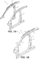
- FIGS. 1A-1D illustrate a door ring assembly 20 of the prior art.
- the door ring assembly 20 includes a first door ring member 22 of stamped structural metal, such as steel or aluminum, with a generally ring shape to define a generally trapezoidal opening for a front door of the vehicle.
- the door ring assembly 20 includes including an A-pillar 30 as a first sloping generally-upright portion extending to a roof edge 32, which is generally horizontal when the door ring assembly 20 in its installed orientation upright within a vehicle body.
- the door ring assembly 20 also includes a B-pillar 34 extending generally upright and transverse to the roof edge 32.
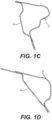
- the door ring assembly 20 includes an A-pillar inner member 24 having a generally flat and elongated shape and extending along an inner side of the first door ring member 22 along the A-pillar and the roof edge 32 and joined together with the first door ring member 22, for example by welding, in a clamshell arrangement to form a tubular shape shown in the cross-sectional views of FIGS. 1C and 1D .
- the door ring assembly 20 also includes a B-pillar inner member 26 that is joined to an inner side of the first door ring member 22 along the upright B-pillar between a lower sill and to the roof edge 32.
- the B-pillar inner member 26 is joined together with the first door ring member 22, for example by welding, in a clamshell arrangement to form a tubular shape.
- each of the A-pillar inner member 24 and the B-pillar inner member 26 are joined to the inner side of the first door ring member 22, which is the side that faces the interior space of the vehicle when the door ring assembly 20 joined with other structural components to form a vehicle body.
- the reverse door ring assembly 120 of the present disclosure includes a door ring member 122 of structural metal, such as steel or aluminum, with a generally ring shape to define a generally trapezoidal opening for a front door of the vehicle.
- the door ring member 122 may be formed from a monolithic piece, tailor-welded blank (TWB), or a C-Ring construction.
- TWB tailor-welded blank
- the reverse door ring assembly 120 of the present disclosure includes a similar overall structure as the door ring assembly 20 shown in FIGS. 1A-1B , including an opening bounded by an A-pillar 30 and a B-pillar 34.
- the door ring member 122 defines an interior face 124 that faces inwardly toward an interior of an assembled vehicle body that includes the reverse door ring assembly 120.
- the door ring member 122 also defines an exterior face 126 opposite of the interior face 124, or facing the exterior of the assembled vehicle.
- the door ring member 122 has a thickness between an inner body side 128 and an outer bodyside 130 that extends parallel to and spaced apart from the inner bodyside 128.
- the door ring member 122 includes a frame portion 132 extending in a plane along the inner body side 128 and surrounding an opening 134 for a door of the vehicle.
- the frame portion 132 may form a sealing surface or a structural foundation for such a sealing surface for a door.
- the door ring member 122 also includes a sill 136 extending in a straight line between a front end 138 and a rear end 139.
- the sill 136 may have a C-shaped cross section or a rectangular cross-section that includes a side wall 140 defining the outer bodyside 130 and extending parallel to and spaced apart from the frame portion 132.
- the sill 136 also includes a ledge 142 extending perpendicularly from the side wall 140 to the inner bodyside 128.
- the door ring member 122 also includes a bulkhead 144 extending perpendicularly from the front end 138 of the sill 136 and defining an upper portion 146 spaced apart from the sill 136.
- the upper portion 146 of the bulkhead 144 includes a shoulder 147 that slopes inwardly and upwardly from the outer body side 130 closest to the sill 136 to the inner bodyside 128 away from the sill 136.
- the door ring member 122 includes an A-pillar base 148 that slopes upwardly from the upper portion 146 of the bulkhead 144 to a roof edge 150 that is parallel to and spaced apart from the sill 136.
- the roof edge 150 is generally horizontal when the reverse door ring assembly 120 in its installed orientation on a vehicle body.
- the A-pillar base 148 thus forms a base portion of the A-pillar of the vehicle.
- the door ring member 122 also includes a B-pillar base 152 that extends from the sill 136 to the roof edge 150.
- the B-pillar base 152 extends perpendicularly to the sill 136.
- the B-pillar base 152 may extend at an oblique angle to the sill 136.
- the reverse door ring assembly 120 also includes an elongate member 160 disposed adjacent the exterior face 126 of the door ring member 122 and extending along the A-pillar base 148 across the B-pillar base 152 and along the roof edge 150 there beyond.
- the elongate member 160 has a tubular shape. More specifically, the elongate member 160 may have a closed cross-section, such as an O-shape or a D-shape for substantially an entire length thereof. For example, the elongate member 160 may have a closed cross-section for the entire length except for a few ports or holes therethrough. In other embodiments, the elongate member 160 may have a C-shaped cross-section.
- the elongate member 160 may be formed of steel, aluminum, or carbon fiber.
- the elongate member 160 may be formed by any suitable means such as, for example, hot metal gas forming hydro-forming, roll form, or extrusion.
- the reverse door ring assembly 120 also includes a B-pillar outer member 170 secured on the exterior face 126 of the door ring member 122 and covering the B-pillar base 152.
- the B-pillar outer member 170 defines a T-shape with a body portion 172 extending along the B-pillar base 152 from a bottom portion 174 to a top portion 176.
- the bottom portion 174 surrounds and engages the sill 136, and the top portion 176 extends along the roof edge 150.
- the B-pillar outer member 170 defines a generally I-shaped profile, which may include the T-shape, with the bottom portion 174 extending perpendicularly to the body portion 172.
- each of the elongate member 160 and the B-pillar outer member 170 are joined to the exterior face 126 of the door ring member 122, which is the side facing outwardly, away from the interior of the vehicle when the reverse door ring assembly 120 is joined with other structural components to form a vehicle body.
- the top portion 176 of the B-pillar outer member 170 covers the elongate member 160 with the elongate member 160 disposed between the door ring member 122 and the B-pillar outer member 170.
- the top portion 176 of the B-pillar outer member 170 defines a rim 178 that extends inwardly toward the door ring member 122 and wraps over a top of the elongate member 160 at the roof edge 150.
- the top portion 176 of the B-pillar outer member 170 at least partially encapsulates the elongate member 160, thus providing a stronger joint.
- the reverse door ring assembly 120 also includes a front reinforcement member 180 that is on the exterior face 126 of the door ring member 122 on the upper portion 146 of the bulkhead 144 and overlying the shoulder 147 of the of the bulkhead 144.
- a support arm 182 extends from the front reinforcement member 180 along the A-pillar base 148 of the door ring member 122.
- the support arm 182 also extends along and supports the elongate member 160.
- the support arm 182 includes a lower wall 184 and a shelf portion 186 extending outwardly therefrom, with the lower wall 184 extending along and adjacent to the A-pillar base 148 of the door ring member 122.
- the shelf portion 186 of the front reinforcement member 180 and the A-pillar base 148 of the door ring member 122 together define a cradle 188 with a Y-shaped cross section holding the elongate member 160 with the elongate member 160 disposed upon the shelf portion 186 of the front reinforcement member 180 and along the A-pillar base 148 of the door ring member 122.
- the reverse door ring assembly 120 also includes a roof support plate 190 fixed to the elongate member 160 at the roof edge 150 spaced away from the A-pillar base 148.
- the roof support plate 190 is fixed to the elongate member 160 at a part of the elongate member 160 rearward of the B-pillar.
- the roof support plate 190 is configured to secure the elongate member 160 to a vehicle structure.
- the vehicle structure may include, for example, metal roof panels and/or structural elements, such as stamped metal beams forming all or part of a rear door opening.
- the reverse door ring assembly 120 of the present disclosure may include its component pieces, including one or more of the door ring member 122, the elongate member 160, the B-pillar outer member 170, the front reinforcement member 180, and the roof support plate 190 joined together by any suitable welding process such as, for example, a structural adhesive, spot welding, laser welding, and/or mig-welding. Two or more different welding processes may be used in constructing the reverse door ring assembly 120.
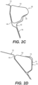
- the reverse door ring assembly 120 of the present disclosure is optimized for crash performance by including four walls at each of the front A-pillar joint as shown in the detail of FIG. 2C and the upper B-pillar joint as shown in the detail of FIG. 2D .
Description
- The present disclosure relates generally to a design structural metal parts for a portion of a body of a motor vehicle. More specifically, the present disclosure relates to design of sheet metal parts for a door ring surrounding a front door opening of a passenger vehicle.
- Various different designs exist using different combinations of structural metal parts to make a door ring surrounding and defining a front door opening of a passenger vehicle, such as a car or truck. Several different design considerations include those pertinent to the finished vehicle, such as weight, roof crush strength, and side impact performance. Additional design considerations relate to the feasibility and economics of manufacturing, which include cost of materials, and manufacturability.
U.S. 2016/200364 provides a vehicle body structure having a sill structure, a roof rail structure, an A-pillar structure defining a pillar cavity, and a reinforcement member. The reinforcement member is attached at its first end to the sill structure, extends within the pillar cavity and terminates at its second end in the roof rail cavity. - The present disclosure provides a reverse door ring assembly for a vehicle, as defined in claim 1. The reverse door ring assembly includes a door ring member defining an interior face and an exterior face opposite of the interior face. The door ring member has a thickness between an inner bodyside and an outer bodyside spaced apart from the inner bodyside. The door ring member includes a sill and a bulkhead extending perpendicularly from a front end of the sill. The bulkhead defines an upper portion spaced apart from the sill. The door ring member also includes an A-pillar base sloping upwardly from the bulkhead to a roof edge. The door ring member includes a B-pillar base extending from the sill to the roof edge. The reverse door ring assembly also includes an elongate member having a tubular shape disposed adj acent the exterior face of the door ring member and extending along the A-pillar base.
- According to another aspect, there is provided a reverse door ring assembly for a vehicle as defined in claim 12. The reverse door ring assembly includes a door ring member defining an interior face and an exterior face opposite of the interior face. The door ring member has a thickness between an inner bodyside and an outer bodyside spaced apart from the inner bodyside. The door ring member includes a bulkhead defining an upper portion. The door ring member also includes an A-pillar base sloping upwardly from the bulkhead to a roof edge. The door ring member also includes a B-pillar base extending perpendicularly to the roof edge. The reverse door ring assembly also includes an elongate member disposed adj acent the exterior face of the door ring member and extending along the A-pillar base. The reverse door ring assembly also includes a B-pillar outer member secured on the exterior face of the door ring member and covering the B-pillar base.
- Further details, features and advantages of designs of the invention result from the following description of embodiment examples in reference to the associated drawings.
-
FIG. 1A is an exploded view of a door ring assembly of the prior art -
FIG. 1B is profile view of the door ring assembly ofFIG. 1A ; -
FIG. 1C is an enlarged cross-sectional view of the door ring assembly ofFIG. 1B along line C-C; -
FIG. 1D is an enlarged cross-sectional view of the door ring assembly ofFIG. 1A along line D-D; -
FIG. 2A is an exploded view of a reverse door ring assembly of the present disclosure; -
FIG. 2B is profile view of the reverse door ring assembly ofFIG. 2A ; -
FIG. 2C is an enlarged cross-sectional view of the reverse door ring assembly ofFIG. 2B along line C-C; and -
FIG. 2D is an enlarged cross-sectional view of the reverse door ring assembly ofFIG. 2B along line D-D. - Recurring features are marked with identical reference numerals in the figures, in which an example embodiment of a reverse door ring for a vehicle, such as a passenger car or truck, is disclosed.
- The reverse door ring provides several advantages over door ring assemblies of the prior art. It allows for a lighter weight body side structure to be constructed with equivalent performance, such as strength against roof crush (rollover) loads and resilience to side-impacts. The transition between the inner bodyside to outer bodyside and vice-versa provides structural unity in bodyside components. Material at the transition portion may act as a bulkhead reinforcement.
-
FIGS. 1A-1D illustrate adoor ring assembly 20 of the prior art. Thedoor ring assembly 20 includes a firstdoor ring member 22 of stamped structural metal, such as steel or aluminum, with a generally ring shape to define a generally trapezoidal opening for a front door of the vehicle. Thedoor ring assembly 20 includes including anA-pillar 30 as a first sloping generally-upright portion extending to aroof edge 32, which is generally horizontal when thedoor ring assembly 20 in its installed orientation upright within a vehicle body. Thedoor ring assembly 20 also includes a B-pillar 34 extending generally upright and transverse to theroof edge 32. - The
door ring assembly 20 includes an A-pillarinner member 24 having a generally flat and elongated shape and extending along an inner side of the firstdoor ring member 22 along the A-pillar and theroof edge 32 and joined together with the firstdoor ring member 22, for example by welding, in a clamshell arrangement to form a tubular shape shown in the cross-sectional views ofFIGS. 1C and 1D . Thedoor ring assembly 20 also includes a B-pillarinner member 26 that is joined to an inner side of the firstdoor ring member 22 along the upright B-pillar between a lower sill and to theroof edge 32. The B-pillarinner member 26 is joined together with the firstdoor ring member 22, for example by welding, in a clamshell arrangement to form a tubular shape. In thedoor ring assembly 20, each of the A-pillarinner member 24 and the B-pillarinner member 26 are joined to the inner side of the firstdoor ring member 22, which is the side that faces the interior space of the vehicle when thedoor ring assembly 20 joined with other structural components to form a vehicle body. - As shown in
FIGS. 2A-2D , the reversedoor ring assembly 120 of the present disclosure includes adoor ring member 122 of structural metal, such as steel or aluminum, with a generally ring shape to define a generally trapezoidal opening for a front door of the vehicle. Thedoor ring member 122 may be formed from a monolithic piece, tailor-welded blank (TWB), or a C-Ring construction. The reversedoor ring assembly 120 of the present disclosure includes a similar overall structure as thedoor ring assembly 20 shown inFIGS. 1A-1B , including an opening bounded by an A-pillar 30 and a B-pillar 34. - As shown in
FIGS. 2A-2B , thedoor ring member 122 defines aninterior face 124 that faces inwardly toward an interior of an assembled vehicle body that includes the reversedoor ring assembly 120. Thedoor ring member 122 also defines anexterior face 126 opposite of theinterior face 124, or facing the exterior of the assembled vehicle. Thedoor ring member 122 has a thickness between aninner body side 128 and anouter bodyside 130 that extends parallel to and spaced apart from theinner bodyside 128. Thedoor ring member 122 includes aframe portion 132 extending in a plane along theinner body side 128 and surrounding anopening 134 for a door of the vehicle. Theframe portion 132 may form a sealing surface or a structural foundation for such a sealing surface for a door. Thedoor ring member 122 also includes asill 136 extending in a straight line between afront end 138 and arear end 139. In some embodiments, thesill 136 may have a C-shaped cross section or a rectangular cross-section that includes aside wall 140 defining theouter bodyside 130 and extending parallel to and spaced apart from theframe portion 132. Thesill 136 also includes aledge 142 extending perpendicularly from theside wall 140 to theinner bodyside 128. - The
door ring member 122 also includes abulkhead 144 extending perpendicularly from thefront end 138 of thesill 136 and defining anupper portion 146 spaced apart from thesill 136. Theupper portion 146 of thebulkhead 144 includes ashoulder 147 that slopes inwardly and upwardly from theouter body side 130 closest to thesill 136 to theinner bodyside 128 away from thesill 136. Thedoor ring member 122 includes anA-pillar base 148 that slopes upwardly from theupper portion 146 of thebulkhead 144 to aroof edge 150 that is parallel to and spaced apart from thesill 136. Theroof edge 150 is generally horizontal when the reversedoor ring assembly 120 in its installed orientation on a vehicle body. TheA-pillar base 148, thus forms a base portion of the A-pillar of the vehicle. Thedoor ring member 122 also includes a B-pillar base 152 that extends from thesill 136 to theroof edge 150. In some embodiments, and as shown inFIGS. 2A-2B , the B-pillar base 152 extends perpendicularly to thesill 136. However, in other embodiments, the B-pillar base 152 may extend at an oblique angle to thesill 136. - The reverse
door ring assembly 120 also includes anelongate member 160 disposed adjacent theexterior face 126 of thedoor ring member 122 and extending along theA-pillar base 148 across the B-pillar base 152 and along theroof edge 150 there beyond. In some embodiments, theelongate member 160 has a tubular shape. More specifically, theelongate member 160 may have a closed cross-section, such as an O-shape or a D-shape for substantially an entire length thereof. For example, theelongate member 160 may have a closed cross-section for the entire length except for a few ports or holes therethrough. In other embodiments, theelongate member 160 may have a C-shaped cross-section. Theelongate member 160 may be formed of steel, aluminum, or carbon fiber. Theelongate member 160 may be formed by any suitable means such as, for example, hot metal gas forming hydro-forming, roll form, or extrusion. - As shown in
FIGS. 2A-2B , the reversedoor ring assembly 120 also includes a B-pillarouter member 170 secured on theexterior face 126 of thedoor ring member 122 and covering the B-pillar base 152. In some embodiments, the B-pillarouter member 170 defines a T-shape with abody portion 172 extending along the B-pillar base 152 from abottom portion 174 to atop portion 176. Thebottom portion 174 surrounds and engages thesill 136, and thetop portion 176 extends along theroof edge 150. In some embodiments, the B-pillarouter member 170 defines a generally I-shaped profile, which may include the T-shape, with thebottom portion 174 extending perpendicularly to thebody portion 172. - In some embodiments, each of the
elongate member 160 and the B-pillarouter member 170 are joined to theexterior face 126 of thedoor ring member 122, which is the side facing outwardly, away from the interior of the vehicle when the reversedoor ring assembly 120 is joined with other structural components to form a vehicle body. - In some embodiments, and as shown in
FIG. 2D , thetop portion 176 of the B-pillarouter member 170 covers theelongate member 160 with theelongate member 160 disposed between thedoor ring member 122 and the B-pillarouter member 170. In some embodiments, thetop portion 176 of the B-pillarouter member 170 defines arim 178 that extends inwardly toward thedoor ring member 122 and wraps over a top of theelongate member 160 at theroof edge 150. Thus, thetop portion 176 of the B-pillarouter member 170 at least partially encapsulates theelongate member 160, thus providing a stronger joint. - As shown in
FIGS. 2A-2B , the reversedoor ring assembly 120 also includes afront reinforcement member 180 that is on theexterior face 126 of thedoor ring member 122 on theupper portion 146 of thebulkhead 144 and overlying theshoulder 147 of the of thebulkhead 144. Asupport arm 182 extends from thefront reinforcement member 180 along theA-pillar base 148 of thedoor ring member 122. Thesupport arm 182 also extends along and supports theelongate member 160. As shown inFIG. 2C , Thesupport arm 182 includes alower wall 184 and ashelf portion 186 extending outwardly therefrom, with thelower wall 184 extending along and adjacent to theA-pillar base 148 of thedoor ring member 122. Theshelf portion 186 of thefront reinforcement member 180 and theA-pillar base 148 of thedoor ring member 122 together define acradle 188 with a Y-shaped cross section holding theelongate member 160 with theelongate member 160 disposed upon theshelf portion 186 of thefront reinforcement member 180 and along theA-pillar base 148 of thedoor ring member 122. - In some embodiments, and as shown in
FIG. 2B , the reversedoor ring assembly 120 also includes aroof support plate 190 fixed to theelongate member 160 at theroof edge 150 spaced away from theA-pillar base 148. In other words, theroof support plate 190 is fixed to theelongate member 160 at a part of theelongate member 160 rearward of the B-pillar. Theroof support plate 190 is configured to secure theelongate member 160 to a vehicle structure. The vehicle structure may include, for example, metal roof panels and/or structural elements, such as stamped metal beams forming all or part of a rear door opening. - The reverse
door ring assembly 120 of the present disclosure may include its component pieces, including one or more of thedoor ring member 122, theelongate member 160, the B-pillarouter member 170, thefront reinforcement member 180, and theroof support plate 190 joined together by any suitable welding process such as, for example, a structural adhesive, spot welding, laser welding, and/or mig-welding. Two or more different welding processes may be used in constructing the reversedoor ring assembly 120. - The reverse
door ring assembly 120 of the present disclosure is optimized for crash performance by including four walls at each of the front A-pillar joint as shown in the detail ofFIG. 2C and the upper B-pillar joint as shown in the detail ofFIG. 2D . - The foregoing description of the embodiments has been provided for purposes of illustration and description. It is not intended to be exhaustive or to limit the disclosure. Individual elements or features of a particular embodiment are generally not limited to that particular embodiment, but, where applicable, are interchangeable and can be used in a selected embodiment, even if not specifically shown or described. The same may also be varied in many ways. Such variations are not to be regarded as a departure from the disclosure, and all such modifications are intended to be included within the scope of the disclosure.
Claims (12)
- A reverse door ring assembly (120) for a vehicle comprising:a door ring member (122) defining an interior face (124) and an exterior face (126) opposite of the interior face, the door ring member having a thickness between an inner bodyside (128) and an outer bodyside (130) spaced apart from the inner bodyside, the door ring member including a sill (136) and a bulkhead (144) extending perpendicularly from a front end (138) of the sill and defining an upper portion (146) spaced apart from the sill, the door ring member including an A-pillar base (148) sloping upwardly from the bulkhead to a roof edge (150), the door ring member including a B-pillar base (152) extending from the sill to the roof edge; andan elongate member (160) having a tubular shape disposed adjacent the exterior face of the door ring member and extending along the A-pillar base; characterised bya front reinforcement member (180) secured on the exterior face of the door ring member on the upper portion of the bulkhead, wherein the upper portion of the bulkhead defines a shoulder (147) sloping inwardly from the outer bodyside toward the inner bodyside; andwherein the front reinforcement member overlies the shoulder of the bulkhead.
- The reverse door ring assembly (120) of Claim 1, wherein the elongate member (160) extends across the B-pillar base (152) and continues along the roof edge (150) beyond the A-pillar base (148).
- The reverse door ring assembly (120) of Claim 1, further comprising a B-pillar outer member (170) secured on the exterior face (126) of the door ring member (122) and covering the B-pillar base (152).
- The reverse door ring assembly (120) of Claim 3, wherein the sill (136) includes a side wall (140) defining the outer bodyside (130) and a ledge (142) extending perpendicularly from the side wall to the inner bodyside (128); and
wherein the B-pillar outer member (170) includes a bottom portion (174) that extends along and around the sill, the bottom portion extending across the ledge and along and adjacent to the side wall of the sill. - The reverse door ring assembly (120) of Claim 3, wherein the B-pillar outer member (170) defines a T-shape with a body portion (172) extending along the B-pillar base (152) from a bottom portion (174) adjacent to the sill (136) to a top portion (176), the top portion extending along the roof edge (150).
- The reverse door ring assembly (120) of Claim 3, wherein the B-pillar outer member (170) includes a top portion spaced (176) apart from the sill (136); and
wherein the top portion of the B-pillar outer member covers the elongate member (160) with the elongate member disposed between the door ring member (122) and the B-pillar outer member. - The reverse door ring assembly (120) of Claim 6, wherein the top portion (176) of the B-pillar outer member (170) defines a rim (178) extending inwardly toward the door ring member (122) and wrapping over a top of the elongate member (160) at the roof edge (150).
- The reverse door ring assembly (120) of any preceding Claim, further comprising a support arm (182) extending from the front reinforcement member (180) along the A-pillar base (148) of the door ring member (122).
- The reverse door ring assembly (120) of Claim 8, wherein the support arm (182) extends along and supports the elongate member (160).
- The reverse door ring assembly (120) of Claim 8, wherein the support arm (182) includes a lower wall (184) and a shelf portion (186) extending outwardly therefrom, with the lower wall extending along and adjacent to the A-pillar base (148) of the door ring member (122); and
wherein the support arm and the A-pillar base of the door ring member together define a cradle (188) with a Y-shaped cross section holding the elongate member (160) therein. - The reverse door ring assembly (120) of Claim 1, further comprising a roof support plate (190) fixed to the elongate member (160) at the roof edge (150) and configured to secure the elongate member to a vehicle structure.
- A reverse door ring assembly (120) for a vehicle comprising:a door ring member (122) defining an interior face (124) and an exterior face (126) opposite of the interior face, the door ring member having a thickness between an inner bodyside (128) and an outer bodyside (130) spaced apart from the inner bodyside, the door ring member including a bulkhead (144) defining an upper portion (146), the door ring member including an A-pillar base (148) sloping upwardly from the bulkhead to a roof edge (150), the door ring member including a B-pillar base (152) extending perpendicularly to the roof edge;an elongate member (160) disposed adjacent the exterior face of the door ring member and extending along the A-pillar base; anda B-pillar outer member (170) secured on the exterior face of the door ring member and covering the B-pillar base, wherein the B-pillar outer member includes a top portion (176) covering the elongate member, with the elongate member disposed between the door ring member and the B-pillar outer member, characterised in that the top portion of the B-pillar outer member defines a rim (178) extending inwardly toward the door ring member and wrapping over a top of the elongate member at the roof edge; wherein the upper portion of the bulkhead defines a shoulder (147) sloping inwardly from the outer bodyside toward the inner bodyside anda front reinforcement member (180) is secured on the exterior face of the door ring member and overlies the shoulder of the bulkhead.
Applications Claiming Priority (2)
| Application Number | Priority Date | Filing Date | Title |
|---|---|---|---|
| US201862718505P | 2018-08-14 | 2018-08-14 | |
| PCT/US2019/046100 WO2020036841A1 (en) | 2018-08-14 | 2019-08-12 | A-b reverse door ring |
Publications (3)
| Publication Number | Publication Date |
|---|---|
| EP3837153A1 EP3837153A1 (en) | 2021-06-23 |
| EP3837153A4 EP3837153A4 (en) | 2022-05-04 |
| EP3837153B1 true EP3837153B1 (en) | 2024-04-03 |
Family
ID=69525844
Family Applications (1)
| Application Number | Title | Priority Date | Filing Date |
|---|---|---|---|
| EP19850317.9A Active EP3837153B1 (en) | 2018-08-14 | 2019-08-12 | A-b reverse door ring |
Country Status (4)
| Country | Link |
|---|---|
| US (1) | US11485419B2 (en) |
| EP (1) | EP3837153B1 (en) |
| CN (1) | CN112566837B (en) |
| WO (1) | WO2020036841A1 (en) |
Families Citing this family (2)
| Publication number | Priority date | Publication date | Assignee | Title |
|---|---|---|---|---|
| CN114987622B (en) * | 2022-04-21 | 2023-06-23 | 岚图汽车科技有限公司 | Thermoforming laser welding integral type door ring structure |
| CN115071834B (en) * | 2022-06-07 | 2023-06-09 | 东风柳州汽车有限公司 | Automobile front door frame structure and automobile |
Family Cites Families (7)
| Publication number | Priority date | Publication date | Assignee | Title |
|---|---|---|---|---|
| JP3446712B2 (en) | 2000-03-10 | 2003-09-16 | 日産自動車株式会社 | Car front body structure |
| DE60232575D1 (en) * | 2002-01-16 | 2009-07-23 | Nissan Motor | Reinforcement construction for body frames of motor vehicles |
| CN102198843B (en) * | 2010-03-23 | 2013-02-20 | 本田技研工业株式会社 | Vehicle side body structure |
| US8491047B1 (en) * | 2012-01-23 | 2013-07-23 | Nissan North America, Inc. | Vehicle body structure |
| US9187135B1 (en) * | 2015-01-09 | 2015-11-17 | Nissan North America, Inc. | Vehicle body structure |
| CN206243254U (en) * | 2016-11-08 | 2017-06-13 | 北京汽车股份有限公司 | Gusset reinforcement structure for vehicle and the vehicle with it |
| CN108058746A (en) * | 2018-01-10 | 2018-05-22 | 北京汽车研究总院有限公司 | Knocker component and with its vehicle |
-
2019
- 2019-08-12 EP EP19850317.9A patent/EP3837153B1/en active Active
- 2019-08-12 US US17/268,202 patent/US11485419B2/en active Active
- 2019-08-12 CN CN201980053071.9A patent/CN112566837B/en active Active
- 2019-08-12 WO PCT/US2019/046100 patent/WO2020036841A1/en unknown
Also Published As
| Publication number | Publication date |
|---|---|
| EP3837153A4 (en) | 2022-05-04 |
| WO2020036841A1 (en) | 2020-02-20 |
| CN112566837A (en) | 2021-03-26 |
| US20210316794A1 (en) | 2021-10-14 |
| EP3837153A1 (en) | 2021-06-23 |
| US11485419B2 (en) | 2022-11-01 |
| CN112566837B (en) | 2023-06-06 |
Similar Documents
| Publication | Publication Date | Title |
|---|---|---|
| JP5927187B2 (en) | Automobile pillar reinforcement | |
| CN102198843B (en) | Vehicle side body structure | |
| US9308941B2 (en) | Vehicle body side portion structure | |
| US8740290B2 (en) | Structure for side section of vehicle body | |
| JP5427895B2 (en) | Body side structure | |
| US8662567B2 (en) | Vehicle roof support pillar assembly | |
| US20160194031A1 (en) | Vehicle body front portion structure | |
| EP2412611B1 (en) | Structure for vehicle body upper portion | |
| US11021191B2 (en) | Structural component for a motor vehicle body | |
| EP3837153B1 (en) | A-b reverse door ring | |
| US20180237072A1 (en) | Vehicle body including reinforcement on rocker panel | |
| JP6344126B2 (en) | Center pillar structure | |
| CN108602417B (en) | Arrangement on a motor vehicle having a crash profile and a load transmission element, load transmission element and motor vehicle or vehicle door | |
| CN110709311B (en) | Panel for vehicle and method for manufacturing same | |
| JP5328057B2 (en) | Energy absorbing beam for vehicle and door structure for vehicle | |
| CN108778907B (en) | Motor vehicle | |
| JP2003127901A (en) | Side part car body structure for automobile | |
| JP4834353B2 (en) | Energy absorbing beam for vehicle and door structure for vehicle | |
| JP5120268B2 (en) | Pillar upper coupling structure | |
| EP1927534B1 (en) | Unitary hydroformed roof support pillar | |
| EP3386843B1 (en) | Method for producing an inner automotive structural part comprising localized reinforced areas | |
| US20200269924A1 (en) | Structure for vehicle | |
| JP5193459B2 (en) | Vehicle roof support assembly and roof support pillar | |
| CN113428235A (en) | Car B post upper joint structure and car | |
| JP3860357B2 (en) | Method for forming reinforcing member for automobile |
Legal Events
| Date | Code | Title | Description |
|---|---|---|---|
| STAA | Information on the status of an ep patent application or granted ep patent |
Free format text: STATUS: THE INTERNATIONAL PUBLICATION HAS BEEN MADE |
|
| PUAI | Public reference made under article 153(3) epc to a published international application that has entered the european phase |
Free format text: ORIGINAL CODE: 0009012 |
|
| STAA | Information on the status of an ep patent application or granted ep patent |
Free format text: STATUS: REQUEST FOR EXAMINATION WAS MADE |
|
| 17P | Request for examination filed |
Effective date: 20210219 |
|
| AK | Designated contracting states |
Kind code of ref document: A1 Designated state(s): AL AT BE BG CH CY CZ DE DK EE ES FI FR GB GR HR HU IE IS IT LI LT LU LV MC MK MT NL NO PL PT RO RS SE SI SK SM TR |
|
| DAV | Request for validation of the european patent (deleted) | ||
| DAX | Request for extension of the european patent (deleted) | ||
| A4 | Supplementary search report drawn up and despatched |
Effective date: 20220405 |
|
| RIC1 | Information provided on ipc code assigned before grant |
Ipc: B62D 25/04 20060101ALI20220330BHEP Ipc: B62D 25/02 20060101AFI20220330BHEP |
|
| GRAP | Despatch of communication of intention to grant a patent |
Free format text: ORIGINAL CODE: EPIDOSNIGR1 |
|
| STAA | Information on the status of an ep patent application or granted ep patent |
Free format text: STATUS: GRANT OF PATENT IS INTENDED |
|
| INTG | Intention to grant announced |
Effective date: 20231218 |
|
| GRAS | Grant fee paid |
Free format text: ORIGINAL CODE: EPIDOSNIGR3 |
|
| P01 | Opt-out of the competence of the unified patent court (upc) registered |
Effective date: 20240119 |
|
| GRAA | (expected) grant |
Free format text: ORIGINAL CODE: 0009210 |
|
| STAA | Information on the status of an ep patent application or granted ep patent |
Free format text: STATUS: THE PATENT HAS BEEN GRANTED |
|
| AK | Designated contracting states |
Kind code of ref document: B1 Designated state(s): AL AT BE BG CH CY CZ DE DK EE ES FI FR GB GR HR HU IE IS IT LI LT LU LV MC MK MT NL NO PL PT RO RS SE SI SK SM TR |
|
| REG | Reference to a national code |
Ref country code: CH Ref legal event code: EP |