EP3836624B1 - Indication information sending method, apparatus and system, and storage medium - Google Patents
Indication information sending method, apparatus and system, and storage medium Download PDFInfo
- Publication number
- EP3836624B1 EP3836624B1 EP19847453.8A EP19847453A EP3836624B1 EP 3836624 B1 EP3836624 B1 EP 3836624B1 EP 19847453 A EP19847453 A EP 19847453A EP 3836624 B1 EP3836624 B1 EP 3836624B1
- Authority
- EP
- European Patent Office
- Prior art keywords
- amf
- pdu session
- indication information
- interworking
- smf
- Prior art date
- Legal status (The legal status is an assumption and is not a legal conclusion. Google has not performed a legal analysis and makes no representation as to the accuracy of the status listed.)
- Active
Links
Images


Classifications
-
- H—ELECTRICITY
- H04—ELECTRIC COMMUNICATION TECHNIQUE
- H04W—WIRELESS COMMUNICATION NETWORKS
- H04W48/00—Access restriction; Network selection; Access point selection
- H04W48/08—Access restriction or access information delivery, e.g. discovery data delivery
-
- H—ELECTRICITY
- H04—ELECTRIC COMMUNICATION TECHNIQUE
- H04W—WIRELESS COMMUNICATION NETWORKS
- H04W36/00—Hand-off or reselection arrangements
- H04W36/0005—Control or signalling for completing the hand-off
- H04W36/0011—Control or signalling for completing the hand-off for data sessions of end-to-end connection
- H04W36/0022—Control or signalling for completing the hand-off for data sessions of end-to-end connection for transferring data sessions between adjacent core network technologies
-
- H—ELECTRICITY
- H04—ELECTRIC COMMUNICATION TECHNIQUE
- H04W—WIRELESS COMMUNICATION NETWORKS
- H04W36/00—Hand-off or reselection arrangements
- H04W36/0005—Control or signalling for completing the hand-off
- H04W36/0011—Control or signalling for completing the hand-off for data sessions of end-to-end connection
- H04W36/0033—Control or signalling for completing the hand-off for data sessions of end-to-end connection with transfer of context information
-
- H—ELECTRICITY
- H04—ELECTRIC COMMUNICATION TECHNIQUE
- H04W—WIRELESS COMMUNICATION NETWORKS
- H04W36/00—Hand-off or reselection arrangements
- H04W36/14—Reselecting a network or an air interface
- H04W36/144—Reselecting a network or an air interface over a different radio air interface technology
-
- H—ELECTRICITY
- H04—ELECTRIC COMMUNICATION TECHNIQUE
- H04W—WIRELESS COMMUNICATION NETWORKS
- H04W36/00—Hand-off or reselection arrangements
- H04W36/24—Reselection being triggered by specific parameters
- H04W36/32—Reselection being triggered by specific parameters by location or mobility data, e.g. speed data
- H04W36/326—Reselection being triggered by specific parameters by location or mobility data, e.g. speed data by proximity to another entity
-
- H—ELECTRICITY
- H04—ELECTRIC COMMUNICATION TECHNIQUE
- H04W—WIRELESS COMMUNICATION NETWORKS
- H04W36/00—Hand-off or reselection arrangements
- H04W36/34—Reselection control
- H04W36/38—Reselection control by fixed network equipment
- H04W36/385—Reselection control by fixed network equipment of the core network
-
- H—ELECTRICITY
- H04—ELECTRIC COMMUNICATION TECHNIQUE
- H04W—WIRELESS COMMUNICATION NETWORKS
- H04W48/00—Access restriction; Network selection; Access point selection
- H04W48/16—Discovering, processing access restriction or access information
-
- H—ELECTRICITY
- H04—ELECTRIC COMMUNICATION TECHNIQUE
- H04W—WIRELESS COMMUNICATION NETWORKS
- H04W8/00—Network data management
- H04W8/02—Processing of mobility data, e.g. registration information at HLR [Home Location Register] or VLR [Visitor Location Register]; Transfer of mobility data, e.g. between HLR, VLR or external networks
- H04W8/08—Mobility data transfer
- H04W8/12—Mobility data transfer between location registers or mobility servers
-
- H—ELECTRICITY
- H04—ELECTRIC COMMUNICATION TECHNIQUE
- H04W—WIRELESS COMMUNICATION NETWORKS
- H04W8/00—Network data management
- H04W8/22—Processing or transfer of terminal data, e.g. status or physical capabilities
- H04W8/24—Transfer of terminal data
-
- H—ELECTRICITY
- H04—ELECTRIC COMMUNICATION TECHNIQUE
- H04W—WIRELESS COMMUNICATION NETWORKS
- H04W92/00—Interfaces specially adapted for wireless communication networks
- H04W92/16—Interfaces between hierarchically similar devices
- H04W92/24—Interfaces between hierarchically similar devices between backbone network devices
-
- H—ELECTRICITY
- H04—ELECTRIC COMMUNICATION TECHNIQUE
- H04W—WIRELESS COMMUNICATION NETWORKS
- H04W92/00—Interfaces specially adapted for wireless communication networks
- H04W92/02—Inter-networking arrangements
Definitions
- the present application relates to the field of communications and, in particular, to an indication information sending method, apparatus and system, and a storage medium.
- PDN connection When a packet data network connection (PDN connection) is established in the 4G system, there is a restriction condition that a mobility management entity (MME) must select the same PDN gateway (PGW) for multiple PDN connections established using the same APN.
- MME mobility management entity
- 3GPP, S2-170851, LG ELECTRONICS INC: "TS 23.502: UE triggered PDU Session Activation procedure in connected mode " relates to the activation of a PDU Session.
- the embodiments of the present disclosure provide an indication information sending method, apparatus and system, a storage medium, and an electronic device to at least solve the problem that interworking across network systems for a user equipment (UE) can not be performed in the related art.
- UE user equipment
- a first AMF sends first indication information to a first target network element, where the first indication information is used for indicating whether a PDU session is capable of interworking with a target network system so that the first target network element can know which PDU session is capable of interworking with the target network system and thus can select the corresponding PDU session, thereby solving the problem that the interworking across network systems for the UE can not be performed in the related art and implementing the inter-network system interworking for the UE between different network systems.
- FIG. 1 illustrates a network architecture which satisfies the bidirectional interworking between 4G and 5G in the related art.
- One core feature is that the architecture is compatible with both 4G and 5G architectures.
- Another core feature is that a PGW-C and an SMF are co-located, a PDN gateway user plane (PGW-U) and a user plane function (UPF) are co-located, a policy control function (PCF) and a policy and charging control function (PCRF) are co-located, and the user plane of the UE is always anchored on the UPF or the PGW-U.
- An N26 interface may or may not be deployed between the AMF and the MME. The system has different flows to handle the case of having the N26 interface deployed and the case of having no N26 interface deployed.
- UE User equipment
- the UE accesses a 4G or 5G network mainly through a wireless air interface and obtains services, and the UE performs information interaction with a base station through an air interface and performs information interaction through non-access stratum (NAS) signaling and a management entity (when the UE accesses the 4G network, the UE interacts with the MME whereas when the UE accesses the 5G network, the UE interacts with the AMF and the SMF) of a core network.
- NAS non-access stratum
- the 4G base station (a radio access network (RAN), an E-Node B (eNB)): the 4G base station is responsible for air interface resource scheduling and air interface connection management of a network which the UE accesses.
- RAN radio access network
- eNB E-Node B
- the 5G base station (a next generation-radio access network (NG RAN), a radio access network): the 5G base station is responsible for air interface resource scheduling and air interface connection management of a network which the UE accesses, and the NG RAN base station may adopt new radio (NR) access technology (gNB) or enhanced Long Term Evolution (eLTE) technology.
- NR new radio
- eLTE enhanced Long Term Evolution
- Mobility management entity the MME is a 4G core network control plane entity and is mainly responsible for user authentication, authorization and subscription checking, user mobility management, PDN connection and bearer maintenance, and paging triggering in a user IDLE state.
- the serving GW is a 4G core network user plane function entity and is mainly responsible for the interaction with a PDN GW in the case of roaming.
- Packet data network gateway (PDN GW): the PDN GW is a 4G core network user plane function entity and an access point through which the UE accesses the PDN network, is responsible for user Internet protocol (IP) address allocation, network-triggered bearer setup, modification and deletion, and QoS control and charging, and is the anchor point of the user in the 3rd Generation Partnership Project (3GPP) system so that the IP address is ensured to be unchanged and service continuity is ensured.
- IP Internet protocol
- 3GPP 3rd Generation Partnership Project
- the P-GW is further divided into two parts: a control entity PGW-C and a user plane entity PGW-U, where the PGW-C is responsible for signaling control and the PGW-U is responsible for IP forwarding.
- HSS Home subscription server
- PCRF Policy and charging control function
- the PCRF is responsible for the formulation of policy and charging rules, provides network control rules based on service data flows, where the network control includes service data flow detection, gating control, Quality of Service (QoS) control, a charging rule based on data flows, and the like, and sends the policy and charging rules formulated by the PCRF itself to the P-GW for execution.
- QoS Quality of Service
- Control functions of the 5G network are illustrated below.
- Session management function the SMF interacts with the UE and is mainly responsible for processing requests of user PDU session setup, modification and deletion, selecting a user plane function (UPF), setting up a user plane connection between the UE and the UPF, and determining, with the PCF, the QoS parameter of the session.
- UPF user plane function
- Access and mobility control function the AMF is a common control plane function in the core network, and a user has only one AMF that is responsible for user authentication, authorization, and subscription checking to ensure that the user is a legitimate user; user mobility management which includes location registration and temporary identity allocation; selecting an appropriate SMF when the user initiates a PDU connection setup request; forwarding the NAS signaling between the UE and the SMF, and forwarding access stratum (AS) signaling between the base station and the SMF.
- AMF Access and mobility control function
- UPF User plane function
- the UPF provides the user plane processing function including data forwarding and QoS execution and also provides user plane anchor points when the user moves to ensure the service continuity.
- PCF Policy Control Function
- Unified data management function (UDM): the UDM stores subscription data of the user and is similar to the HSS in the 4G era.
- the UE When the UE requests to set up a PDU session in the 5G system, the UE carries a DNN parameter to indicate the data network to which the PDU session is connected, and meanwhile, the UE allocates a unique PDU session identifier (ID) in this UE and sends this unique PDU session ID to the network.
- ID unique PDU session identifier
- the UE When the UE sets up a PDU connection in the 4G system, the UE carries an APN parameter to indicate the data network to which the PDU connection is connected. In order to ensure the interworking for the UE between 4G and 5G, there is a mapping relationship between the APN and the PDN.
- the network when the UE sets up or modifies the PDU session in the 5G system, the network generates a session parameter corresponding to the 4G PDN connection and sends the session parameter to the UE.
- the UE When the UE sets up or modifies the PDU connection in the 4G system, the UE generates a corresponding PDU session ID and sends the PDU session ID to the SMF+PGW-C, and the SMF+PGW-C also generates a session parameter corresponding to the 5G PDU session and sends the session parameter to the UE.
- a mobility process handover, or idle state mobility
- a target system When a mobility process (handover, or idle state mobility) between the 4G and 5G systems occurs for a UE, a target system generates a corresponding PDN connection/PDU Session at the target system according to session information created by a source system.
- the SMF+PGW-C stores DNN and PGW-C identification information (such as PGW-C Fully Qualified Domain Name (FQDN)) corresponding to this PDU session in the context of this session of the UE in the UDM or the HSS.
- PGW-C identification information such as PGW-C Fully Qualified Domain Name (FQDN)
- FQDN Fully Qualified Domain Name
- the UE requests to re-establish the PDN connection, indicates that this session is an existing session, and carries PDU session ID information.
- the MME obtains the APN (mapped from the DNN) and PGW-C identification information from the UDM or the HSS, matches the APN and PGW-C identification information with the APN received from the UE, and sends the session setup request to the PGW corresponding to the PGW-C identification information (through the S-GW).
- the SMF+PGW-C after receiving the session setup request, finds the corresponding session according to the PDU session ID in this request and completes the re-establishment at the 4G side.
- the SMF+PGW-C stores APN and PGW-C identification information (such as PGW-C FQDN) corresponding to this PDU connection in the UDM or the HSS.
- PGW-C identification information such as PGW-C FQDN
- the selection of different SMF+PGW-C in the 5G system means that after the session is tranferred to the 4G system, multiple different PDN connections under the same APN have different PGWs, which violates the principle of the 4G system.
- the 5G system in order to ensure the uniqueness of the PGW in the 4G system, the 5G system must decide that the PDU session under a certain SMF can perform interworking with the 4G system while the PDU sessions under other SMFs cannot perform interworking with the 4G system.
- the first problem is how the SMF knows whether the PDU session established by the UE on this SMF can perform interworking with the 4G system.
- the SMF can determine whether PDU session can perform interworking through whether the AMF allocates an EBI, but when the network is not deployed with the N26 interface, the SMF cannot know about that.
- the SMF/PGW does not know whether it supports interworking, when the SMF/PGW receives the re-establishement request sent by the MME after moving to the 4G system, the SMF/PGW probably refuses to set up the PDU connection.
- the second problem is how the UDM or the HSS handles the PGW identity.
- the UE sets up two PDU sessions by using DNN1.
- the SMF of PDU session 1 is SMF A+PGW-C A
- the SMF of PDU session 2 is SMF_B+PGW-C_B.
- the UDM or the HSS delivers subscription data to the MME, only one PGW identity is delivered for APN1 mapped by DNN1.
- the UDM or the HSS cannot determine which PGW identity to send to the MME to let the MME know on which PGW the PDN connection can be set up.
- FIG. 2 is a block diagram showing hardware structures of a mobile terminal for an indication information sending method according to an embodiment of the present disclosure.
- a mobile terminal 10 may include one or more (only one is shown in FIG. 2 ) processors 102 (the processors 102 may include, but are not limited to, a microprocessor such as a microcontroller unit (MCU), a programmable logic device such as a field-programmable gate array (FPGA), and other processing apparatuses), and a memory 104 used for storing data.
- MCU microcontroller unit
- FPGA field-programmable gate array
- the preceding mobile terminal may further include a transmission device 106 for a communication function and an input/output device 108.
- a transmission device 106 for a communication function may further include more or fewer components than the components shown in FIG. 2 or may have a configuration different from the configuration shown in FIG. 2 .
- the memory 104 may be configured to store a computer program such as a software program and a module of application software, for example, the computer program corresponding to the indication information sending method in the embodiment of the present disclosure.
- the processor 102 executes the computer program stored in the memory 104 to perform various functional applications and data processing, that is, to implement the method described above.
- the memory 104 may include a high-speed random access memory, and may further include a nonvolatile memory such as one or more magnetic storage apparatuses, flash memories, or other nonvolatile solid-state memories.
- the memory 104 may further include memories that are remotely disposed with respect to the processors 102. These remote memories may be connected to the mobile terminal 10 via a network.
- the examples of the preceding network include, but are not limited to, the Internet, an intranet, a local area network, a mobile communication network, and a combination thereof.
- the transmission device 106 is configured to receive or send data via a network.
- Specific examples of the preceding network may include a wireless network provided by a communication provider of the mobile terminal 10.
- the transmission device 106 includes a network interface controller (NIC) which may be connected to other network devices via a base station and thus can communicate with the Internet.
- the transmission device 106 may be a radio frequency (RF) module which is configured to communicate with the Internet in a wireless way.
- RF radio frequency
- FIG. 3 is a flowchart of an indication information sending method according to an embodiment of the present disclosure. As shown in FIG. 3 , the method includes the step described below.
- a first AMF sends first indication information to a first target network element, where the first indication information is used for indicating whether a PDU session can perform interwoking in the target network system.
- a first AMF sends first indication information to a first target network element, where the first indication information is used for indicating whether a PDU session can perform interworking to the target network system so that the first target network element can know which PDU session can perform interworking to the target network system and thus can select the corresponding PDU session, thereby solving the problem that the SMF or the PGW does not know whether it can support interworking and thus the interworking across network systems for the UE can not be performed in the related art and implementing the cross-network system interworking for the UE between different network systems.
- target network system herein may be a 4G system, a 3G system, or a 5G system, and may also be any other network systems that need to implement the cross-network interworking , which is not limited in the embodiment of the present disclosure.
- the above step S301 may be implemented in the following manner: in response to the first AMF receiving a message in which a UE requests to set up the PDU session, the first AMF sends a PDU session setup request to an SMF, where the PDU session setup request carries the first indication information, and the first indication information is used for indicating whether the PDU session can perform interworkingin the target network system.
- the setup request message is sent from the first AMF to the SMF, and in the PDU session setup process, the first indication information carried in the setup request message may be used for indicating whether the currently established PDU session can perform the interworking in the target network system.
- the above step S301 may be implemented in the following manner: in response to the first AMF determining that a status parameter of the PDU session changes, the first AMF sends a PDU session modification request to an SMF, where the PDU session modification request carries the first indication information, and the first indication information is used for indicating whether the PDU session can perform interworking in the target network system.
- the modification request message is sent from the first AMF to the SMF, and in the PDU session modification process, the first indication information carried in the modification request message may be used for indicating whether the currently modified PDU session can perform the interworking in the target network system. That the status parameter changes may be that the state of the current PDU session changes from a state of being able to perform interworking in the target network system to a state of not being able to perform interworking in the target network system, or that the state of the current PDU session changes from a state of not being able to perform interworking in the target network system to a state of being able to perform interworking in the target network system.
- step S301 may further be implemented in the following manner: in response to a inter-AMF mobility event in which the UE is transferred from the first AMF to a second AMF occurring, the first AMF sends the first indication information to the second AMF, where the first indication information is used for indicating whether the PDU session of the UE under the first AMF can perform interworking in the target network system.
- the inter-AMF mobility event herein includes at least one of a connected state handover process or an idle state mobility process.
- the message carried in the first indication information may be whether part or all of PDU sessions belonging to the same UE under the first AMF can perform interworking in the target network system.
- the step in which the first AMF sends the first indication information to the second AMF may be implemented in the following manner: the first AMF sends a UE context message to the second AMF, where the UE context message carries the first indication information.
- the above step S301 may further be implemented in the following manner: the first AMF sends the first indication information to the SMF, where the first indication information is used for indicating whether the PDU session under the SMF can perform interworking in the target network system; and in response to an inter-AMF mobility event in which the UE is transferred from the first AMF to a second AMF occurring, the SMF sends a message the second AMF, where the message is used for indicating whether the PDU session under the SMF can perform interworking in the target network system.
- the process herein may be understood that when a mobility event occurs, the first AMF does not directly send the first indication information to the second AMF but sends the first indication information to the SMF, and the SMF may indicate whether the PDU session under the current SMF can perform interworking in the target network system by sending a message to the second AMF.
- FIG. 4 is a flowchart of an indication information sending method according to an embodiment of the present disclosure. As shown in FIG. 4 , the method includes the step described below.
- step S401 a first AMF sends second indication information to a second target network element.
- a first AMF sends second indication information to a second target network element, where the second indication information is used for indicating that the second target network element stores DNN interworking information, thereby solving the problem that the UDM or the HSS cannot determine to send which one to the MME to let the MME know on which PGW the PDU connection can be re-established and thus the interworking across network systems for the UE can not be performed in the related art and implementing the cross-network system interworking for the UE between different network systems.
- the step S401 may be implemented in the following manner: the first AMF sends the second indication information to a UDM or an HSS, where the second indication information is used for indicating that the UDM or the HSS stores the DNN interworking information, and the DNN interworking information includes DNN information and at least one of: an SMF address or a PGW address.
- the UDM or the HSS stores one piece of DNN interworking information corresponding to the DNN.
- each DNN has an independent message to store corresponding interworking information, for example, DNN1 corresponds to multiple SMFs/PGWs, but only SMF1 and/or PGW1 can support interworking across network systems, and in this case, the stored DNN interworking information may include (DNN1, SMF 1) or (DNN1, PGW 1) or (DNN1, SMF1, PGW1).
- the above step S401 may be implemented in the following manner: in response to an inter-AMF mobility event in which the UE is transferred from the first AMF to a second AMF occurring, the first AMF sends the second indication information to the second AMF, where the second indication information is used for indicating to store the DNN interworking information, and the DNN interworking information includes DNN information and at least one of: an SMF address or a PGW address.
- the inter-AMF mobility event herein includes at least one of a connected state handover process or an idle state mobility process.
- the DNN interworking information carried in the second indication information may be part or all of DNN interworking information belonging to the same UE under the first AMF.
- the step in which the first AMF sends the second indication information to the second AMF may be implemented in the following manner: the first AMF sends a UE context message to the second AMF, where the UE context message carries the second indication information.
- an indication information sending apparatus is further provided.
- the apparatus is configured to implement the preceding embodiment and preferred implementations. What has been described will not be repeated.
- the term "module” may be software, hardware, or a combination thereof capable of implementing predetermined functions.
- the apparatus described below in this embodiment is implemented by software, but implementation by hardware or by a combination of software and hardware is also possible and conceived.
- an indication information sending apparatus is further provided.
- the apparatus is applied to a first AMF and is configured to implement the above method.
- FIG. 5 is a structural block diagram of an indication information sending apparatus according to an embodiment of the present disclosure.
- the apparatus includes a first sending module 50, which is configured to send first indication information to a target network element, where the first indication information is used for indicating whether a PDU session can perform interworking in the target network system.
- the problem that the SMF or the PGW does not know whether it can support interworking and thus the interworking across network systems for the UE can not be performed in the related art can be solved, and the cross-network system interworking for the UE between different network systems can be implemented.
- the first sending module 50 includes a first sending unit, which is configured to, in response to the first AMF receiving a message in which a UE requests to set up the PDU session, send PDU session setup requestto an SMF, where the PDU session setup request carries the first indication information, and the first indication information is used for indicating whether the PDU session can perform interworking in the target network system.
- the first sending module 50 further includes a second sending unit, which is configured to, in response to the first AMF determining that a status parameter of the PDU session changes, send a PDU session modification request to an SMF, where the PDU session modification request carries the first indication information, and the first indication information is used for indicating whether the PDU session can perform the interworking in the target network system.
- a second sending unit which is configured to, in response to the first AMF determining that a status parameter of the PDU session changes, send a PDU session modification request to an SMF, where the PDU session modification request carries the first indication information, and the first indication information is used for indicating whether the PDU session can perform the interworking in the target network system.
- the first sending module 50 further includes a third sending unit, which is configured to, in response to an inter-AMF mobility event in which the UE transfers from the first AMF to a second AMF occurring, send the first indication information to the second AMF, where the first indication information is used for indicating whether the PDU session of the UE under the first AMF can perform the interworking in the target network system.
- a third sending unit which is configured to, in response to an inter-AMF mobility event in which the UE transfers from the first AMF to a second AMF occurring, send the first indication information to the second AMF, where the first indication information is used for indicating whether the PDU session of the UE under the first AMF can perform the interworking in the target network system.
- an indication information sending apparatus is further provided.
- the apparatus is applied to a first AMF and is configured to implement the above method.
- FIG. 6 is a structural block diagram of an indication information sending apparatus according to an embodiment of the present disclosure.
- the apparatus includes a second sending module 60, which is configured to send second indication information to a second target network element, where the second indication information is used for indicating that the second target network element stores DNN interworking information.
- a first AMF sends second indication information to a second target network element, where the second indication information is used for indicating that the second target network element stores DNN interworking information, thereby solving the problem that the UDM or the HSS cannot determine to send which one to the MME to let the MME know on which PGW the PDN connection can be re-established and thus the interworking across network systems for the UE can not be performed in the related art and implementing the cross-network system interworking for the UE between different network systems.
- the second sending module 60 includes a fourth sending unit, which is configured to send the second indication information to a UDM or an HSS, where the second indication information is used for indicating that the UDM or the HSS stores the DNN interworking information, and the DNN interworking information includes DNN information and at least one of: an SMF address or a PGW address.
- the UDM or the HSS stores one piece of DNN interworking information corresponding to the DNN.
- the second sending module 60 further includes a fifth sending unit, which is configured to, in response to an inter-AMF mobility event in which the UE is tranferred the first AMF to a second AMF occurring, send the second indication information to the second AMF, where the second indication information is used for indicating to store the DNN interworking information, and the DNN interworking information includes DNN information and at least one of: an SMF address or a PGW address.
- a fifth sending unit which is configured to, in response to an inter-AMF mobility event in which the UE is tranferred the first AMF to a second AMF occurring, send the second indication information to the second AMF, where the second indication information is used for indicating to store the DNN interworking information, and the DNN interworking information includes DNN information and at least one of: an SMF address or a PGW address.
- FIG. 7 is a structural block diagram of an indication information sending system according to an embodiment of the present disclosure. As shown in FIG. 7 , the system includes: a first AMF 70, which is configured to send first indication information to a target network element; and a first target network element 72, which is configured to determine whether a PDU session can perform interworking in a target network system according to the first indication information.
- a first AMF 70 which is configured to send first indication information to a target network element
- a first target network element 72 which is configured to determine whether a PDU session can perform interworking in a target network system according to the first indication information.
- the problem that the SMF or the PGW does not know whether it can support interworking and thus the interworking across network systems for the UE can not be performed in the related art can be solved, and the cross-network system interworking for the UE between different network systems can be implemented.
- the first target network element 72 includes an SMF, and in response to the first AMF receiving a message in which a UE requests to set up the PDU session, the first AMF is further configured to send a PDU session setup request to the SMF, where the PDU session setup request carries the first indication information, and the SMF is configured to determine whether the PDU session can perform interworking in a target network system according to the first indication information.
- the first AMF in response to the first AMF determining that a status parameter of the PDU session changes, is further configured to send PDU session modification request to an SMF, where the PDU session modification request carries the first indication information, and the SMF is configured to determine whether the PDU session whose status parameter has changed can perform interworking in the target network system.
- the first target network element 72 further includes a second AMF, and in response to a inter-AMF mobility event in which the UE transfers from the first AMF to a second AMF occurring, the first AMF is further configured to send the second indication information to the second AMF, and the second AMF is configured to determine whether the PDU session under the first AMF can perform interworking in the target network system according to the first indication information.
- FIG. 8 is a structural block diagram of an indication information sending system according to an embodiment of the present disclosure. As shown in FIG. 8 , the system includes: a first AMF 70, which is configured to send second indication information to a second target network element, where the second indication information carries DNN interworking information; and a second target network element 80, which is configured to store the DNN interworking information according to the second indication information.
- a first AMF 70 which is configured to send second indication information to a second target network element, where the second indication information carries DNN interworking information
- a second target network element 80 which is configured to store the DNN interworking information according to the second indication information.
- a first AMF sends second indication information to a second target network element, where the second indication information is used for indicating that the second target network element stores DNN interworking information, thereby solving the problem that the UDM or the HSS cannot determine to send which one to the MME to let the MME know on which PGW the PDN connection can be re-established and thus the interworking across network systems for the UE can not be performed in the related art and implementing the cross-network system interworking for the UE between different network systems.
- the second target network element includes a UDM or an HSS
- the UDM or the HSS is configured to store the DNN interworking information according to the second indication information, where the DNN interworking information includes DNN information and at least one of: an SMF address or a PGW address.
- the second target network element includes a second AMF, and in response to a inter-AMF mobility event in which the UE transfers from the first AMF to a second AMF occurring, the first AMF is further configured to send the second indication information to the second AMF, where the second indication information carries the DNN interworking information, and the second AMF is configured to store the DNN interworking information according to the second indication information, where the DNN interworking information includes DNN information and at least one of: an SMF address or a PGW address.
- the embodiments of the present disclosure provide the following examples to illustrate specific application scenarios by using an example in which the UE moves from the 5G system to the 4G system.
- the example proposes that the AMF informs the SMF in the process of PDU session setup and modification whether the PDU session or the PDU session of the UE on this SMF can perform interworking with the 4G system.
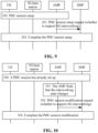
- FIG. 9 is a flowchart of a PDU session setup method according to an example one of the present disclosure. As shown in FIG. 9 , the setup process includes the steps described below.
- step 200 the UE requests to set up a PDU session.
- step 201 the AMF sends a PDU session setup request to the SMF, where the PDU session setup request carries indication information indicating whether the PDU session can perform interworking with the 4G system.
- step 202 the PDU session setup process is completed.
- FIG. 10 is a flowchart of a PDU session modification method according to the example one of the present disclosure. As shown in FIG. 10 , the modification process includes the steps described below.
- step 300 the UE has set up the PDU session, where the status of the PDU session may be that the PDU session can perform interworking with the 4G system or that the PDU session cannot perform intreworking.
- step 301 the AMF determines that the status of interworking with 4G of the PDU session changes.
- the AMF sends a PDU session modification request to the SMF, where the PDU session modification request carries indication information indicating whether the PDU session can perform interworking with the 4G system. For example, the status of the PDU session, which was that the PDU session cannot perform interworking, now becomes that the PDU session can perform interworking; or the status of the PDU session, which was that the PDU session can perform interworking, now becomes that the PDU session cannot perform interworking.
- step 303 the PDU session modification process is completed.
- the SMF and the AMF always support interworking by default, and when the interworking status changes, the SMF needs to be notified (that is, only the steps in FIG. 10 need executing).
- the source AMF In response to a inter-AMF mobility process occurs, such as the process of connected state handover or idle state mobility, the source AMF (which may be equivalent to the first AMF in the above embodiments) needs to send an indication indicating whether the PDU session supports interworking with 4G to the target AMF (which may be equivalent to the second AMF in the above embodiments).
- FIG. 11 is a flowchart of a inter-AMF mobility process according to an example two of the present disclosure. As shown in FIG. 11 , the mobility process includes the steps described below.
- step 400 the UE has set up the PDU session, where the status of the PDU session may be that the PDU session can perform interworkingwith the 4G system or that the PDU session cannot perform interworking.
- the UE has a inter-AMF mobility process such as the process of the connected state handover or idle state mobility.
- the UE context sent by the source AMF to the target AMF carries an indication indicating whether the PDU session supports the interworking with 4G or carries an indication indicating whether PDU sessions under a certain SMF support the interworking with 4G.
- step 403 the inter-AMF mobility process is completed.
- the SMF In response to a inter-AMF mobility process occurs, such as the process of connected state handover or idle state mobility, the SMF sends an indication indicating whether the PDU session supports interworking with 4G to the target AMF.
- FIG. 12 is a flowchart of a inter-AMF mobility process according to an example three of the present disclosure. As shown in FIG. 12 , the mobility process includes the steps described below.
- step 500 the UE has set up the PDU session, where the status of the PDU session may be that the PDU session can perform interworkingwith the 4G system or that the PDU session cannot perform interworking.
- the UE has a inter-AMF mobility process such as the process of the connected state handover or idle state mobility.
- step 502 the target AMF sends PDU session update to the SMF.
- step 503 the SMF sends a PDU session update response to the target AMF, where the PDU session update response carries an indication indicating whether the PDU session supports interworking with 4G.
- step 504 the inter-AMF mobility process is completed.
- the AMF For each DNN in which the PDU session is set up with the UE, the AMF stores interworking information in the UDM or the HSS, modifies the interworking information, or deletes the interworking information from the UDM or the HSS, where the information includes DNN and PGW identification information and/or SMF identification information and may also include corresponding access types.
- the information is not stored in each PDU session context on each UDM or HSS, and for the UE, for each DNN, there is a piece of independent 4G-5G interworking information.
- the UDM or the HSS sends APN and PGW identification information to the MME.
- FIG. 13 is a flowchart illustrating an interworking information sending process according to an example four of the present disclosure. As shown in FIG. 13 , the method includes the steps described below.
- step 600 a PDU session is set up or modified for the UE.
- the AMF stores 4G-5G interworking information in the UDM or the HSS, where the information includes a DNN and corresponding PGW-C identification information and/or SMF identification information, and/or corresponding access types (for example, 3GPP access or non-3GPP access).
- the AMF may delete the above-mentioned 4G-5G interworking information stored in the UDM or the HSS.
- the information is not stored in each PDU session context of the UE in the UDM or the HSS, and for the UE, for each DNN, there is a piece of 4G-5G interworking information.
- a piece of 4G-5G interworking information is stored each DNN.
- the source AMF In response to a inter-AMF mobility process occurs, such as the process of connected state handover or idle state mobility, the source AMF needs to send 4G-5G interworking information to the target AMF.
- the information includes a DNN and corresponding PGW-C identification information and/or SMF identification information and/or corresponding access types (for example, 3GPP access or non-3GPP access).
- FIG. 14 is a flowchart illustrating an interworking information sending process according to an example five of the present disclosure. As shown in FIG. 14 , the method includes the steps described below.
- step 700 the UE has set up the PDU session, where the status of the PDU session may be that the PDU session can perform interworking with the 4G system or that the PDU session cannot perform interworking with 4G.
- the UE has a inter-AMF mobility process such as the process of the connected state handover or idle state mobility.
- the UE context sent by the source AMF to the target AMF carries 4G-5G interworking information.
- the information includes a DNN and corresponding PGW-C identification information and/or SMF identification information and/or corresponding access types (for example, 3GPP access or non-3GPP access).
- step 703 the inter-AMF mobility process is completed.
- the SMF stores interworking information in the UDM or the HSS, where the information includes DNN and PGW identification information and/or SMF identification information and may also include corresponding access types.
- the information is not stored in the PDU session context in the UDM or the HSS, and for the UE, for each DNN, there is a piece of 4G-5G interworking information.
- the UDM or the HSS sends APN and PGW identification information to the MME.
- FIG. 15 is a flowchart illustrating an interworking information sending process according to an example six of the present disclosure. As shown in FIG. 15 , the method includes the steps described below.
- step 800 a PDU session is set up or modified for the UE.
- the SMF stores 4G-5G interworking information in the UDM or the HSS, where the information includes a DNN and corresponding PGW-C identification information and/or SMF identification information, and/or corresponding access types (for example, 3GPP access or non-3GPP access).
- the information is not stored in the PDU session context in the UDM or the HSS, and for the UE, for the DNN of the PDU session, there is a piece of independent 4G-5G interworking information.
- a piece of 4G-5G interworking information is stored each DNN.
- the embodiment of the present application further provides a storage medium.
- the storage medium stores a computer program which is configured to, when executed, perform the steps in any one of the preceding method embodiments
- the storage medium may be configured to store a computer program for executing the following step: S1, a first AMF sends first indication information to a first target network element, where the first indication information is used for indicating whether a PDU session can perform interworking in a target network system.
- the storage medium is further configured to store a computer program for executing the following step: in response to the first AMF receiving a message in which a UE requests to set up the PDU session, the first AMF sends PDU session setup request to an SMF, where the PDU session setup request carries the first indication information, and the first indication information is used for indicating whether the PDU session can perform interworking in the target network system.
- the storage medium is further configured to store a computer program for executing the following step: in response to the first AMF determining that a status parameter of the PDU session changes, the first AMF sends a PDU session modification request to an SMF, where the PDU session modification request carries the first indication information, and the first indication information is used for indicating whether the PDU session can perform interworking in the target network system.
- the storage medium is further configured to store a computer program for executing the following step: in response to a inter-AMF mobility event in which the UE transfers from the first AMF to a second AMF occurring, the first AMF sends the first indication information to the second AMF, where the first indication information is used for indicating whether the PDU session of the UE under the first AMF can perform interworking in the target network system.
- the storage medium may be configured to store a computer program for executing the following step: S1, a first AMF sends second indication information to a second target network element, where the second indication information is used for in which the second target network element store DNN interworking information.
- the storage medium is further configured to store a computer program for executing the following step: the first AMF sends the second indication information to a UDM or an HSS, where the second indication information is used for indicating that the UDM or the HSS stores the DNN interworking information, and the DNN interworking information includes DNN information and at least one of: an SMF address or a PGW address.
- the storage medium is further configured to store a computer program for executing the following step: in response to a inter-AMF mobility event in which the UE transfers from the first AMF to a second AMF occurring, the first AMF sends the second indication information to the second AMF, where the second indication information is used for indicating that the UDM or the HSS stores the DNN interworking information, and the DNN interworking information includes DNN information and at least one of: an SMF address or a PGW address.
- the storage medium may include, but is not limited to, a USB flash drive, a read-only memory (ROM), a random access memory (RAM), a mobile hard disk, a magnetic disk, an optical disk or another medium capable of storing a computer program.
- the embodiments of the present application further provide an electronic device.
- the electronic device includes a memory and a processor.
- the memory stores a computer program
- the processor is configured to execute the computer program to perform the steps in any one of the preceding method embodiments.
- the electronic apparatus may further include a transmission device and an input/output device. Both the transmission device and the input/output device are connected to the processor.
- the processor may be configured to perform the following step through a computer program.
- a first AMF sends first indication information to a target network element, where the first indication information is used for indicating whether a PDU session can perform interworking in a target network system.
- the processor is further configured to perform the following step through a computer program.
- the first AMF In response to the first AMF receiving a message in which a UE requests to set up the PDU session, the first AMF sends a PDU session setup request to an SMF, where the PDU session setup request carries the first indication information, and the first indication information is used for indicating whether the PDU session can perform interworking in the target network system.
- the processor is further configured to perform the following step through a computer program.
- the first AMF In response to the first AMF determining that a status parameter of the PDU session changes, the first AMF sends PDU session modification request to an SMF, where the PDU session modification request carries the first indication information, and the first indication information is used for indicating whether the PDU session can perform interworking in the target network system.
- the processor is further configured to perform the following step through a computer program: in response to an inter-AMF mobility event in which the UE is transferred from the first AMF to a second AMF occurring, the first AMF sends the first indication information to the second AMF, where the first indication information is used for indicating whether the PDU session of the UE under the first AMF can perform interworking in the target network system.
- the processor is further configured to perform the following step through a computer program: S1, a first AMF sends second indication information to a second target network element, where the second indication information is used for indicating that the second target network element stores DNN interworking information.
- the processor is further configured to perform the following step through a computer program: the first AMF sends the second indication information to a UDM or an HSS, where the second indication information is used for indicating that the UDM or the HSS stores the DNN interworking information, and the DNN interworking information includes DNN information and at least one of: an SMF address or a PGW address.
- the processor is further configured to perform the following step through a computer program: in response to an inter-AMF mobility event in which the UE is transferred from the first AMF to a second AMF occurring, the first AMF sends the second indication information to the second AMF, where the second indication information is used for indicating that the UDM or the HSS stores the DNN interworking information, and the DNN interworking information includes DNN information and at least one of: an SMF address or a PGW address.
- each of the modules or steps of the present application may be implemented by a general-purpose computing apparatus and may be concentrated on a single computing apparatus or distributed on a network formed by multiple computing apparatuses.
- these modules or steps may be implemented by program codes executable by the computing apparatus.
- these modules or steps may be stored in a storage apparatus and executed by the computing apparatus.
- the illustrated or described steps may be executed in sequences different from the sequence described herein.
- these modules or steps may be implemented by being made into integrated circuit modules separately or multiple ones of these modules or steps may be implemented by being made into a single integrated circuit module. In this manner, the present application is not limited to any specific combination of hardware and software.
Landscapes
- Engineering & Computer Science (AREA)
- Computer Networks & Wireless Communication (AREA)
- Signal Processing (AREA)
- Databases & Information Systems (AREA)
- Computer Security & Cryptography (AREA)
- Mobile Radio Communication Systems (AREA)
- Computer And Data Communications (AREA)
- Communication Control (AREA)
- Data Exchanges In Wide-Area Networks (AREA)
Priority Applications (1)
| Application Number | Priority Date | Filing Date | Title |
|---|---|---|---|
| EP24185486.8A EP4432770A3 (en) | 2018-08-10 | 2019-08-10 | Indication information sending method, apparatus and system, and storage medium |
Applications Claiming Priority (2)
| Application Number | Priority Date | Filing Date | Title |
|---|---|---|---|
| CN201810912161.6A CN110831086B (zh) | 2018-08-10 | 2018-08-10 | 指示信息的发送方法、装置及系统、存储介质 |
| PCT/CN2019/100111 WO2020030166A1 (zh) | 2018-08-10 | 2019-08-10 | 指示信息的发送方法、装置及系统、存储介质 |
Related Child Applications (1)
| Application Number | Title | Priority Date | Filing Date |
|---|---|---|---|
| EP24185486.8A Division EP4432770A3 (en) | 2018-08-10 | 2019-08-10 | Indication information sending method, apparatus and system, and storage medium |
Publications (3)
| Publication Number | Publication Date |
|---|---|
| EP3836624A1 EP3836624A1 (en) | 2021-06-16 |
| EP3836624A4 EP3836624A4 (en) | 2021-12-15 |
| EP3836624B1 true EP3836624B1 (en) | 2024-07-24 |
Family
ID=69413991
Family Applications (2)
| Application Number | Title | Priority Date | Filing Date |
|---|---|---|---|
| EP19847453.8A Active EP3836624B1 (en) | 2018-08-10 | 2019-08-10 | Indication information sending method, apparatus and system, and storage medium |
| EP24185486.8A Pending EP4432770A3 (en) | 2018-08-10 | 2019-08-10 | Indication information sending method, apparatus and system, and storage medium |
Family Applications After (1)
| Application Number | Title | Priority Date | Filing Date |
|---|---|---|---|
| EP24185486.8A Pending EP4432770A3 (en) | 2018-08-10 | 2019-08-10 | Indication information sending method, apparatus and system, and storage medium |
Country Status (8)
| Country | Link |
|---|---|
| US (2) | US11974355B2 (https=) |
| EP (2) | EP3836624B1 (https=) |
| JP (2) | JP7507144B2 (https=) |
| KR (2) | KR20250037578A (https=) |
| CN (1) | CN110831086B (https=) |
| AU (1) | AU2019316896B2 (https=) |
| SG (1) | SG11202101411PA (https=) |
| WO (1) | WO2020030166A1 (https=) |
Families Citing this family (5)
| Publication number | Priority date | Publication date | Assignee | Title |
|---|---|---|---|---|
| CN115604753A (zh) * | 2021-07-09 | 2023-01-13 | 展讯半导体(南京)有限公司(Cn) | 会话建立方法、装置、系统、电子设备、存储介质 |
| CN116017405B (zh) * | 2021-10-22 | 2025-09-09 | 华为技术有限公司 | 一种通信方法及装置 |
| CN114363912B (zh) * | 2021-12-28 | 2024-08-06 | 天翼物联科技有限公司 | 异构网络的数据传输方法、系统、计算机装置和存储介质 |
| US12317360B2 (en) * | 2022-05-09 | 2025-05-27 | Hewlett Packard Enterprise Development Lp | Session continuity for a user equipment |
| CN120201412A (zh) * | 2023-12-22 | 2025-06-24 | 华为技术有限公司 | 通信方法、通信装置以及通信系统 |
Family Cites Families (24)
| Publication number | Priority date | Publication date | Assignee | Title |
|---|---|---|---|---|
| CA2789634A1 (en) * | 2010-02-11 | 2011-08-18 | Telefonaktiebolaget L M Ericsson (Publ) | Interworking between systems using different ip mobility management protocols |
| CN107592328A (zh) * | 2016-07-08 | 2018-01-16 | 中兴通讯股份有限公司 | 会话连续的实现方法、装置及系统 |
| JP6925411B2 (ja) * | 2016-08-16 | 2021-08-25 | アイディーエーシー ホールディングス インコーポレイテッド | ネットワークスライス再選択 |
| EP3557905A4 (en) * | 2016-12-15 | 2020-08-12 | LG Electronics Inc. -1- | METHOD FOR PERFORMING A HANDOVER IN A WIRELESS COMMUNICATION SYSTEM AND DEVICE FOR IT |
| KR102549946B1 (ko) * | 2017-01-09 | 2023-06-30 | 삼성전자주식회사 | 이동통신 환경에서 단말의 초기 접속 요청 메시지를 라우팅하는 방법 및 관련 파라미터 |
| EP3603179B1 (en) * | 2017-03-21 | 2021-01-06 | Telefonaktiebolaget LM Ericsson (PUBL) | Method and node for handling handover in 5g networks |
| CN107018542A (zh) * | 2017-03-27 | 2017-08-04 | 中兴通讯股份有限公司 | 网络系统中状态信息的处理方法、装置及存储介质 |
| US10264506B2 (en) * | 2017-05-13 | 2019-04-16 | Qualcomm Incorporated | Enable a network-trigger change of network slices |
| CN109005565B (zh) * | 2017-06-06 | 2022-11-04 | 大唐移动通信设备有限公司 | 一种会话管理方法和装置 |
| KR102224248B1 (ko) * | 2017-06-09 | 2021-03-08 | 삼성전자주식회사 | 통신 시스템에서 PDU(Protocol Data Unit) 세션을 설립하는 방법 |
| US11184842B2 (en) * | 2017-06-13 | 2021-11-23 | Nokia Technologies Oy | Conveying non-access stratum messages over ethernet |
| KR102388936B1 (ko) * | 2017-06-14 | 2022-04-22 | 삼성전자 주식회사 | 단말의 망 접속 방법 및 이동성 지원과 데이터 전달 방법 및 장치 |
| WO2019033269A1 (zh) * | 2017-08-15 | 2019-02-21 | 华为技术有限公司 | 一种会话建立的方法及设备 |
| US10757611B2 (en) * | 2017-09-22 | 2020-08-25 | Ofinno, Llc | SMF and AMF relocation during UE registration |
| US11463929B2 (en) * | 2017-09-28 | 2022-10-04 | Lg Electronics Inc. | Method for transmitting and receiving signal related to handover from 5GS to EPS in wireless communication system and device therefor |
| EP3673682B1 (en) * | 2017-09-28 | 2023-12-27 | Ofinno, LLC | Smf, amf and upf relocation during ue registration |
| KR102371810B1 (ko) | 2017-10-20 | 2022-03-10 | 삼성전자주식회사 | 다중 무선 접속 기술(Multi-Radio Access Technology)을 지원하는 무선 접속 시스템에서 단말이 데이터를 송수신하기 위한 방법 및 장치. |
| CN111357339B (zh) * | 2017-11-13 | 2022-12-20 | Lg电子株式会社 | 在无线通信系统中发送和接收与切换接入有关的信号的方法及其设备 |
| WO2019098745A1 (ko) * | 2017-11-19 | 2019-05-23 | 엘지전자 주식회사 | 무선 통신 시스템에서의 핸드오버 방법 및 이를 위한 장치 |
| US10986602B2 (en) * | 2018-02-09 | 2021-04-20 | Intel Corporation | Technologies to authorize user equipment use of local area data network features and control the size of local area data network information in access and mobility management function |
| CN116709594A (zh) * | 2018-02-14 | 2023-09-05 | 华为技术有限公司 | 确定协议数据单元会话服务网元的方法和装置 |
| WO2019158973A1 (en) * | 2018-02-15 | 2019-08-22 | Telefonaktiebolaget Lm Ericsson (Publ) | Method for providing a breakout pdu session for local ip access |
| US10986528B2 (en) * | 2018-02-15 | 2021-04-20 | Huawei Technologies Co., Ltd. | Tracking QoS violated events |
| CN110324840B (zh) * | 2018-03-31 | 2022-04-05 | 华为技术有限公司 | 一种更新配置的方法及装置 |
-
2018
- 2018-08-10 CN CN201810912161.6A patent/CN110831086B/zh active Active
-
2019
- 2019-08-10 WO PCT/CN2019/100111 patent/WO2020030166A1/zh not_active Ceased
- 2019-08-10 EP EP19847453.8A patent/EP3836624B1/en active Active
- 2019-08-10 JP JP2021507086A patent/JP7507144B2/ja active Active
- 2019-08-10 KR KR1020257006730A patent/KR20250037578A/ko active Pending
- 2019-08-10 AU AU2019316896A patent/AU2019316896B2/en active Active
- 2019-08-10 EP EP24185486.8A patent/EP4432770A3/en active Pending
- 2019-08-10 KR KR1020217004163A patent/KR102872742B1/ko active Active
- 2019-08-10 SG SG11202101411PA patent/SG11202101411PA/en unknown
-
2021
- 2021-02-10 US US17/172,711 patent/US11974355B2/en active Active
-
2024
- 2024-04-24 US US18/644,457 patent/US12587827B2/en active Active
- 2024-06-19 JP JP2024098882A patent/JP7785853B2/ja active Active
Also Published As
| Publication number | Publication date |
|---|---|
| KR20210042916A (ko) | 2021-04-20 |
| EP4432770A2 (en) | 2024-09-18 |
| KR20250037578A (ko) | 2025-03-17 |
| AU2019316896B2 (en) | 2024-05-09 |
| JP2021534654A (ja) | 2021-12-09 |
| JP7507144B2 (ja) | 2024-06-27 |
| SG11202101411PA (en) | 2021-03-30 |
| AU2019316896A1 (en) | 2021-03-11 |
| KR102872742B1 (ko) | 2025-10-16 |
| WO2020030166A1 (zh) | 2020-02-13 |
| JP2024123131A (ja) | 2024-09-10 |
| US11974355B2 (en) | 2024-04-30 |
| EP3836624A1 (en) | 2021-06-16 |
| CN110831086B (zh) | 2022-09-13 |
| US20240276196A1 (en) | 2024-08-15 |
| US12587827B2 (en) | 2026-03-24 |
| EP3836624A4 (en) | 2021-12-15 |
| JP7785853B2 (ja) | 2025-12-15 |
| CN110831086A (zh) | 2020-02-21 |
| US20210168585A1 (en) | 2021-06-03 |
| EP4432770A3 (en) | 2025-04-16 |
Similar Documents
| Publication | Publication Date | Title |
|---|---|---|
| US11503523B2 (en) | Network handover method, apparatus and system, and handover determination method and apparatus | |
| US12587827B2 (en) | Indication information sending method, apparatus and system, and storage medium | |
| US12207089B2 (en) | User equipment, intra-core network apparatus, and communication control method | |
| US8855045B2 (en) | Method and system for controlling establishment of local IP access | |
| US20190394684A1 (en) | Method and device for determining a bearer identifier, and storage medium therefor | |
| US12150046B2 (en) | User equipment and core network apparatus | |
| WO2009117879A1 (zh) | 一种指示服务网关承载管理的方法 | |
| WO2018059401A1 (zh) | 网络切换方法、装置及系统,网络接入方法及装置 | |
| CN111988821A (zh) | 语音通信方法及其装置 | |
| US10616752B2 (en) | Method and device for processing terminal unloading and processing terminal registration | |
| WO2018045928A1 (zh) | 网络拥塞控制的方法及装置 | |
| CN101998567B (zh) | 终端转为连接态时更改服务网关的连接激活方法及系统 | |
| EP3833075A1 (en) | Session migration method and device | |
| WO2016086611A1 (zh) | 获取PGW FQDN的方法、Home PGW及系统 | |
| JP2024538935A (ja) | アクセスタイプごとのネットワークスライス受付制御のための方法 | |
| CN107548167A (zh) | 用户设备的控制方法、装置及系统和网关 | |
| WO2016150115A1 (zh) | 一种承载建立方法、分组数据网关、服务网关及系统 | |
| CN114846843A (zh) | 请求分组数据网络连接信息的通信方法 | |
| BR112020002580B1 (pt) | Equipamento de usuário e métodos de operação relacionados | |
| BR112020002580A2 (pt) | dipositivo sem fio e entidade ou função de rede núcleo para prover controle de gap de serviço e métodos de operação relacionados | |
| WO2012097524A1 (zh) | 移动管理网元复位的处理方法、设备及系统 |
Legal Events
| Date | Code | Title | Description |
|---|---|---|---|
| STAA | Information on the status of an ep patent application or granted ep patent |
Free format text: STATUS: THE INTERNATIONAL PUBLICATION HAS BEEN MADE |
|
| PUAI | Public reference made under article 153(3) epc to a published international application that has entered the european phase |
Free format text: ORIGINAL CODE: 0009012 |
|
| STAA | Information on the status of an ep patent application or granted ep patent |
Free format text: STATUS: REQUEST FOR EXAMINATION WAS MADE |
|
| 17P | Request for examination filed |
Effective date: 20210210 |
|
| AK | Designated contracting states |
Kind code of ref document: A1 Designated state(s): AL AT BE BG CH CY CZ DE DK EE ES FI FR GB GR HR HU IE IS IT LI LT LU LV MC MK MT NL NO PL PT RO RS SE SI SK SM TR |
|
| RIC1 | Information provided on ipc code assigned before grant |
Ipc: H04W 76/22 20180101ALI20210802BHEP Ipc: H04W 36/00 20090101AFI20210802BHEP |
|
| DAV | Request for validation of the european patent (deleted) | ||
| DAX | Request for extension of the european patent (deleted) | ||
| A4 | Supplementary search report drawn up and despatched |
Effective date: 20211111 |
|
| RIC1 | Information provided on ipc code assigned before grant |
Ipc: H04W 76/22 20180101ALI20211105BHEP Ipc: H04W 36/00 20090101AFI20211105BHEP |
|
| STAA | Information on the status of an ep patent application or granted ep patent |
Free format text: STATUS: EXAMINATION IS IN PROGRESS |
|
| 17Q | First examination report despatched |
Effective date: 20230306 |
|
| GRAP | Despatch of communication of intention to grant a patent |
Free format text: ORIGINAL CODE: EPIDOSNIGR1 |
|
| STAA | Information on the status of an ep patent application or granted ep patent |
Free format text: STATUS: GRANT OF PATENT IS INTENDED |
|
| INTG | Intention to grant announced |
Effective date: 20240417 |
|
| GRAS | Grant fee paid |
Free format text: ORIGINAL CODE: EPIDOSNIGR3 |
|
| GRAA | (expected) grant |
Free format text: ORIGINAL CODE: 0009210 |
|
| STAA | Information on the status of an ep patent application or granted ep patent |
Free format text: STATUS: THE PATENT HAS BEEN GRANTED |
|
| AK | Designated contracting states |
Kind code of ref document: B1 Designated state(s): AL AT BE BG CH CY CZ DE DK EE ES FI FR GB GR HR HU IE IS IT LI LT LU LV MC MK MT NL NO PL PT RO RS SE SI SK SM TR |
|
| RAP3 | Party data changed (applicant data changed or rights of an application transferred) |
Owner name: ZTE CORPORATION |
|
| REG | Reference to a national code |
Ref country code: GB Ref legal event code: FG4D |
|
| REG | Reference to a national code |
Ref country code: CH Ref legal event code: EP |
|
| REG | Reference to a national code |
Ref country code: IE Ref legal event code: FG4D Ref country code: DE Ref legal event code: R096 Ref document number: 602019055857 Country of ref document: DE |
|
| REG | Reference to a national code |
Ref country code: LT Ref legal event code: MG9D |
|
| REG | Reference to a national code |
Ref country code: NL Ref legal event code: MP Effective date: 20240724 |
|
| PG25 | Lapsed in a contracting state [announced via postgrant information from national office to epo] |
Ref country code: PT Free format text: LAPSE BECAUSE OF FAILURE TO SUBMIT A TRANSLATION OF THE DESCRIPTION OR TO PAY THE FEE WITHIN THE PRESCRIBED TIME-LIMIT Effective date: 20241125 |
|
| REG | Reference to a national code |
Ref country code: AT Ref legal event code: MK05 Ref document number: 1707429 Country of ref document: AT Kind code of ref document: T Effective date: 20240724 |
|
| PG25 | Lapsed in a contracting state [announced via postgrant information from national office to epo] |
Ref country code: NL Free format text: LAPSE BECAUSE OF FAILURE TO SUBMIT A TRANSLATION OF THE DESCRIPTION OR TO PAY THE FEE WITHIN THE PRESCRIBED TIME-LIMIT Effective date: 20240724 |
|
| PG25 | Lapsed in a contracting state [announced via postgrant information from national office to epo] |
Ref country code: PT Free format text: LAPSE BECAUSE OF FAILURE TO SUBMIT A TRANSLATION OF THE DESCRIPTION OR TO PAY THE FEE WITHIN THE PRESCRIBED TIME-LIMIT Effective date: 20241125 Ref country code: NL Free format text: LAPSE BECAUSE OF FAILURE TO SUBMIT A TRANSLATION OF THE DESCRIPTION OR TO PAY THE FEE WITHIN THE PRESCRIBED TIME-LIMIT Effective date: 20240724 |
|
| PG25 | Lapsed in a contracting state [announced via postgrant information from national office to epo] |
Ref country code: NO Free format text: LAPSE BECAUSE OF FAILURE TO SUBMIT A TRANSLATION OF THE DESCRIPTION OR TO PAY THE FEE WITHIN THE PRESCRIBED TIME-LIMIT Effective date: 20241024 |
|
| PG25 | Lapsed in a contracting state [announced via postgrant information from national office to epo] |
Ref country code: FI Free format text: LAPSE BECAUSE OF FAILURE TO SUBMIT A TRANSLATION OF THE DESCRIPTION OR TO PAY THE FEE WITHIN THE PRESCRIBED TIME-LIMIT Effective date: 20240724 Ref country code: GR Free format text: LAPSE BECAUSE OF FAILURE TO SUBMIT A TRANSLATION OF THE DESCRIPTION OR TO PAY THE FEE WITHIN THE PRESCRIBED TIME-LIMIT Effective date: 20241025 Ref country code: PL Free format text: LAPSE BECAUSE OF FAILURE TO SUBMIT A TRANSLATION OF THE DESCRIPTION OR TO PAY THE FEE WITHIN THE PRESCRIBED TIME-LIMIT Effective date: 20240724 |
|
| PG25 | Lapsed in a contracting state [announced via postgrant information from national office to epo] |
Ref country code: BG Free format text: LAPSE BECAUSE OF FAILURE TO SUBMIT A TRANSLATION OF THE DESCRIPTION OR TO PAY THE FEE WITHIN THE PRESCRIBED TIME-LIMIT Effective date: 20240724 |
|
| PG25 | Lapsed in a contracting state [announced via postgrant information from national office to epo] |
Ref country code: LV Free format text: LAPSE BECAUSE OF FAILURE TO SUBMIT A TRANSLATION OF THE DESCRIPTION OR TO PAY THE FEE WITHIN THE PRESCRIBED TIME-LIMIT Effective date: 20240724 |
|
| PG25 | Lapsed in a contracting state [announced via postgrant information from national office to epo] |
Ref country code: AT Free format text: LAPSE BECAUSE OF FAILURE TO SUBMIT A TRANSLATION OF THE DESCRIPTION OR TO PAY THE FEE WITHIN THE PRESCRIBED TIME-LIMIT Effective date: 20240724 Ref country code: IS Free format text: LAPSE BECAUSE OF FAILURE TO SUBMIT A TRANSLATION OF THE DESCRIPTION OR TO PAY THE FEE WITHIN THE PRESCRIBED TIME-LIMIT Effective date: 20241124 |
|
| PG25 | Lapsed in a contracting state [announced via postgrant information from national office to epo] |
Ref country code: HR Free format text: LAPSE BECAUSE OF FAILURE TO SUBMIT A TRANSLATION OF THE DESCRIPTION OR TO PAY THE FEE WITHIN THE PRESCRIBED TIME-LIMIT Effective date: 20240724 |
|
| PG25 | Lapsed in a contracting state [announced via postgrant information from national office to epo] |
Ref country code: ES Free format text: LAPSE BECAUSE OF FAILURE TO SUBMIT A TRANSLATION OF THE DESCRIPTION OR TO PAY THE FEE WITHIN THE PRESCRIBED TIME-LIMIT Effective date: 20240724 Ref country code: RS Free format text: LAPSE BECAUSE OF FAILURE TO SUBMIT A TRANSLATION OF THE DESCRIPTION OR TO PAY THE FEE WITHIN THE PRESCRIBED TIME-LIMIT Effective date: 20241024 |
|
| PG25 | Lapsed in a contracting state [announced via postgrant information from national office to epo] |
Ref country code: RS Free format text: LAPSE BECAUSE OF FAILURE TO SUBMIT A TRANSLATION OF THE DESCRIPTION OR TO PAY THE FEE WITHIN THE PRESCRIBED TIME-LIMIT Effective date: 20241024 Ref country code: PL Free format text: LAPSE BECAUSE OF FAILURE TO SUBMIT A TRANSLATION OF THE DESCRIPTION OR TO PAY THE FEE WITHIN THE PRESCRIBED TIME-LIMIT Effective date: 20240724 Ref country code: NO Free format text: LAPSE BECAUSE OF FAILURE TO SUBMIT A TRANSLATION OF THE DESCRIPTION OR TO PAY THE FEE WITHIN THE PRESCRIBED TIME-LIMIT Effective date: 20241024 Ref country code: LV Free format text: LAPSE BECAUSE OF FAILURE TO SUBMIT A TRANSLATION OF THE DESCRIPTION OR TO PAY THE FEE WITHIN THE PRESCRIBED TIME-LIMIT Effective date: 20240724 Ref country code: IS Free format text: LAPSE BECAUSE OF FAILURE TO SUBMIT A TRANSLATION OF THE DESCRIPTION OR TO PAY THE FEE WITHIN THE PRESCRIBED TIME-LIMIT Effective date: 20241124 Ref country code: HR Free format text: LAPSE BECAUSE OF FAILURE TO SUBMIT A TRANSLATION OF THE DESCRIPTION OR TO PAY THE FEE WITHIN THE PRESCRIBED TIME-LIMIT Effective date: 20240724 Ref country code: GR Free format text: LAPSE BECAUSE OF FAILURE TO SUBMIT A TRANSLATION OF THE DESCRIPTION OR TO PAY THE FEE WITHIN THE PRESCRIBED TIME-LIMIT Effective date: 20241025 Ref country code: FI Free format text: LAPSE BECAUSE OF FAILURE TO SUBMIT A TRANSLATION OF THE DESCRIPTION OR TO PAY THE FEE WITHIN THE PRESCRIBED TIME-LIMIT Effective date: 20240724 Ref country code: ES Free format text: LAPSE BECAUSE OF FAILURE TO SUBMIT A TRANSLATION OF THE DESCRIPTION OR TO PAY THE FEE WITHIN THE PRESCRIBED TIME-LIMIT Effective date: 20240724 Ref country code: BG Free format text: LAPSE BECAUSE OF FAILURE TO SUBMIT A TRANSLATION OF THE DESCRIPTION OR TO PAY THE FEE WITHIN THE PRESCRIBED TIME-LIMIT Effective date: 20240724 Ref country code: AT Free format text: LAPSE BECAUSE OF FAILURE TO SUBMIT A TRANSLATION OF THE DESCRIPTION OR TO PAY THE FEE WITHIN THE PRESCRIBED TIME-LIMIT Effective date: 20240724 |
|
| REG | Reference to a national code |
Ref country code: CH Ref legal event code: PL |
|
| PG25 | Lapsed in a contracting state [announced via postgrant information from national office to epo] |
Ref country code: SM Free format text: LAPSE BECAUSE OF FAILURE TO SUBMIT A TRANSLATION OF THE DESCRIPTION OR TO PAY THE FEE WITHIN THE PRESCRIBED TIME-LIMIT Effective date: 20240724 Ref country code: RO Free format text: LAPSE BECAUSE OF FAILURE TO SUBMIT A TRANSLATION OF THE DESCRIPTION OR TO PAY THE FEE WITHIN THE PRESCRIBED TIME-LIMIT Effective date: 20240724 Ref country code: DK Free format text: LAPSE BECAUSE OF FAILURE TO SUBMIT A TRANSLATION OF THE DESCRIPTION OR TO PAY THE FEE WITHIN THE PRESCRIBED TIME-LIMIT Effective date: 20240724 |
|
| PG25 | Lapsed in a contracting state [announced via postgrant information from national office to epo] |
Ref country code: LU Free format text: LAPSE BECAUSE OF NON-PAYMENT OF DUE FEES Effective date: 20240810 |
|
| P01 | Opt-out of the competence of the unified patent court (upc) registered |
Free format text: CASE NUMBER: APP_12763/2025 Effective date: 20250314 |
|
| PG25 | Lapsed in a contracting state [announced via postgrant information from national office to epo] |
Ref country code: EE Free format text: LAPSE BECAUSE OF FAILURE TO SUBMIT A TRANSLATION OF THE DESCRIPTION OR TO PAY THE FEE WITHIN THE PRESCRIBED TIME-LIMIT Effective date: 20240724 Ref country code: MC Free format text: LAPSE BECAUSE OF FAILURE TO SUBMIT A TRANSLATION OF THE DESCRIPTION OR TO PAY THE FEE WITHIN THE PRESCRIBED TIME-LIMIT Effective date: 20240724 Ref country code: CH Free format text: LAPSE BECAUSE OF NON-PAYMENT OF DUE FEES Effective date: 20240831 |
|
| PG25 | Lapsed in a contracting state [announced via postgrant information from national office to epo] |
Ref country code: CZ Free format text: LAPSE BECAUSE OF FAILURE TO SUBMIT A TRANSLATION OF THE DESCRIPTION OR TO PAY THE FEE WITHIN THE PRESCRIBED TIME-LIMIT Effective date: 20240724 |
|
| REG | Reference to a national code |
Ref country code: DE Ref legal event code: R097 Ref document number: 602019055857 Country of ref document: DE |
|
| PG25 | Lapsed in a contracting state [announced via postgrant information from national office to epo] |
Ref country code: SK Free format text: LAPSE BECAUSE OF FAILURE TO SUBMIT A TRANSLATION OF THE DESCRIPTION OR TO PAY THE FEE WITHIN THE PRESCRIBED TIME-LIMIT Effective date: 20240724 Ref country code: IT Free format text: LAPSE BECAUSE OF FAILURE TO SUBMIT A TRANSLATION OF THE DESCRIPTION OR TO PAY THE FEE WITHIN THE PRESCRIBED TIME-LIMIT Effective date: 20240724 |
|
| PLBE | No opposition filed within time limit |
Free format text: ORIGINAL CODE: 0009261 |
|
| STAA | Information on the status of an ep patent application or granted ep patent |
Free format text: STATUS: NO OPPOSITION FILED WITHIN TIME LIMIT |
|
| REG | Reference to a national code |
Ref country code: BE Ref legal event code: MM Effective date: 20240831 |
|
| 26N | No opposition filed |
Effective date: 20250425 |
|
| PGFP | Annual fee paid to national office [announced via postgrant information from national office to epo] |
Ref country code: GB Payment date: 20250619 Year of fee payment: 7 |
|
| PG25 | Lapsed in a contracting state [announced via postgrant information from national office to epo] |
Ref country code: BE Free format text: LAPSE BECAUSE OF NON-PAYMENT OF DUE FEES Effective date: 20240831 |
|
| PGFP | Annual fee paid to national office [announced via postgrant information from national office to epo] |
Ref country code: FR Payment date: 20250610 Year of fee payment: 7 |
|
| PG25 | Lapsed in a contracting state [announced via postgrant information from national office to epo] |
Ref country code: IE Free format text: LAPSE BECAUSE OF NON-PAYMENT OF DUE FEES Effective date: 20240810 |
|
| PG25 | Lapsed in a contracting state [announced via postgrant information from national office to epo] |
Ref country code: SE Free format text: LAPSE BECAUSE OF FAILURE TO SUBMIT A TRANSLATION OF THE DESCRIPTION OR TO PAY THE FEE WITHIN THE PRESCRIBED TIME-LIMIT Effective date: 20240724 |
|
| PGFP | Annual fee paid to national office [announced via postgrant information from national office to epo] |
Ref country code: DE Payment date: 20250618 Year of fee payment: 7 |
|
| PG25 | Lapsed in a contracting state [announced via postgrant information from national office to epo] |
Ref country code: CY Free format text: LAPSE BECAUSE OF FAILURE TO SUBMIT A TRANSLATION OF THE DESCRIPTION OR TO PAY THE FEE WITHIN THE PRESCRIBED TIME-LIMIT; INVALID AB INITIO Effective date: 20190810 |
|
| PG25 | Lapsed in a contracting state [announced via postgrant information from national office to epo] |
Ref country code: HU Free format text: LAPSE BECAUSE OF FAILURE TO SUBMIT A TRANSLATION OF THE DESCRIPTION OR TO PAY THE FEE WITHIN THE PRESCRIBED TIME-LIMIT; INVALID AB INITIO Effective date: 20190810 |