EP3836476A1 - Method and apparatus for sending reference signal, method and apparatus for receiving reference signal, vehicle-mounted device, and terminal - Google Patents
Method and apparatus for sending reference signal, method and apparatus for receiving reference signal, vehicle-mounted device, and terminal Download PDFInfo
- Publication number
- EP3836476A1 EP3836476A1 EP18929816.9A EP18929816A EP3836476A1 EP 3836476 A1 EP3836476 A1 EP 3836476A1 EP 18929816 A EP18929816 A EP 18929816A EP 3836476 A1 EP3836476 A1 EP 3836476A1
- Authority
- EP
- European Patent Office
- Prior art keywords
- vssb
- target
- information
- reference signal
- time domain
- Prior art date
- Legal status (The legal status is an assumption and is not a legal conclusion. Google has not performed a legal analysis and makes no representation as to the accuracy of the status listed.)
- Granted
Links
Images





Classifications
-
- H—ELECTRICITY
- H04—ELECTRIC COMMUNICATION TECHNIQUE
- H04L—TRANSMISSION OF DIGITAL INFORMATION, e.g. TELEGRAPHIC COMMUNICATION
- H04L5/00—Arrangements affording multiple use of the transmission path
- H04L5/003—Arrangements for allocating sub-channels of the transmission path
- H04L5/0037—Inter-user or inter-terminal allocation
-
- H—ELECTRICITY
- H04—ELECTRIC COMMUNICATION TECHNIQUE
- H04J—MULTIPLEX COMMUNICATION
- H04J11/00—Orthogonal multiplex systems, e.g. using WALSH codes
- H04J11/0069—Cell search, i.e. determining cell identity [cell-ID]
-
- H—ELECTRICITY
- H04—ELECTRIC COMMUNICATION TECHNIQUE
- H04J—MULTIPLEX COMMUNICATION
- H04J11/00—Orthogonal multiplex systems, e.g. using WALSH codes
- H04J11/0069—Cell search, i.e. determining cell identity [cell-ID]
- H04J11/0073—Acquisition of primary synchronisation channel, e.g. detection of cell-ID within cell-ID group
-
- H—ELECTRICITY
- H04—ELECTRIC COMMUNICATION TECHNIQUE
- H04J—MULTIPLEX COMMUNICATION
- H04J11/00—Orthogonal multiplex systems, e.g. using WALSH codes
- H04J11/0069—Cell search, i.e. determining cell identity [cell-ID]
- H04J11/0076—Acquisition of secondary synchronisation channel, e.g. detection of cell-ID group
-
- H—ELECTRICITY
- H04—ELECTRIC COMMUNICATION TECHNIQUE
- H04L—TRANSMISSION OF DIGITAL INFORMATION, e.g. TELEGRAPHIC COMMUNICATION
- H04L27/00—Modulated-carrier systems
- H04L27/26—Systems using multi-frequency codes
- H04L27/2601—Multicarrier modulation systems
- H04L27/2602—Signal structure
- H04L27/26025—Numerology, i.e. varying one or more of symbol duration, subcarrier spacing, Fourier transform size, sampling rate or down-clocking
-
- H—ELECTRICITY
- H04—ELECTRIC COMMUNICATION TECHNIQUE
- H04L—TRANSMISSION OF DIGITAL INFORMATION, e.g. TELEGRAPHIC COMMUNICATION
- H04L5/00—Arrangements affording multiple use of the transmission path
- H04L5/003—Arrangements for allocating sub-channels of the transmission path
- H04L5/0048—Allocation of pilot signals, i.e. of signals known to the receiver
-
- H—ELECTRICITY
- H04—ELECTRIC COMMUNICATION TECHNIQUE
- H04L—TRANSMISSION OF DIGITAL INFORMATION, e.g. TELEGRAPHIC COMMUNICATION
- H04L5/00—Arrangements affording multiple use of the transmission path
- H04L5/003—Arrangements for allocating sub-channels of the transmission path
- H04L5/0048—Allocation of pilot signals, i.e. of signals known to the receiver
- H04L5/0051—Allocation of pilot signals, i.e. of signals known to the receiver of dedicated pilots, i.e. pilots destined for a single user or terminal
-
- H—ELECTRICITY
- H04—ELECTRIC COMMUNICATION TECHNIQUE
- H04L—TRANSMISSION OF DIGITAL INFORMATION, e.g. TELEGRAPHIC COMMUNICATION
- H04L5/00—Arrangements affording multiple use of the transmission path
- H04L5/003—Arrangements for allocating sub-channels of the transmission path
- H04L5/0053—Allocation of signalling, i.e. of overhead other than pilot signals
-
- H—ELECTRICITY
- H04—ELECTRIC COMMUNICATION TECHNIQUE
- H04L—TRANSMISSION OF DIGITAL INFORMATION, e.g. TELEGRAPHIC COMMUNICATION
- H04L5/00—Arrangements affording multiple use of the transmission path
- H04L5/003—Arrangements for allocating sub-channels of the transmission path
- H04L5/0058—Allocation criteria
- H04L5/006—Quality of the received signal, e.g. BER, SNR, water filling
-
- H—ELECTRICITY
- H04—ELECTRIC COMMUNICATION TECHNIQUE
- H04W—WIRELESS COMMUNICATION NETWORKS
- H04W4/00—Services specially adapted for wireless communication networks; Facilities therefor
- H04W4/30—Services specially adapted for particular environments, situations or purposes
- H04W4/40—Services specially adapted for particular environments, situations or purposes for vehicles, e.g. vehicle-to-pedestrians [V2P]
-
- H—ELECTRICITY
- H04—ELECTRIC COMMUNICATION TECHNIQUE
- H04W—WIRELESS COMMUNICATION NETWORKS
- H04W48/00—Access restriction; Network selection; Access point selection
- H04W48/08—Access restriction or access information delivery, e.g. discovery data delivery
- H04W48/10—Access restriction or access information delivery, e.g. discovery data delivery using broadcasted information
-
- H—ELECTRICITY
- H04—ELECTRIC COMMUNICATION TECHNIQUE
- H04W—WIRELESS COMMUNICATION NETWORKS
- H04W56/00—Synchronisation arrangements
- H04W56/001—Synchronization between nodes
-
- H—ELECTRICITY
- H04—ELECTRIC COMMUNICATION TECHNIQUE
- H04W—WIRELESS COMMUNICATION NETWORKS
- H04W72/00—Local resource management
- H04W72/20—Control channels or signalling for resource management
-
- H—ELECTRICITY
- H04—ELECTRIC COMMUNICATION TECHNIQUE
- H04W—WIRELESS COMMUNICATION NETWORKS
- H04W72/00—Local resource management
- H04W72/20—Control channels or signalling for resource management
- H04W72/23—Control channels or signalling for resource management in the downlink direction of a wireless link, i.e. towards a terminal
-
- H—ELECTRICITY
- H04—ELECTRIC COMMUNICATION TECHNIQUE
- H04W—WIRELESS COMMUNICATION NETWORKS
- H04W72/00—Local resource management
- H04W72/20—Control channels or signalling for resource management
- H04W72/25—Control channels or signalling for resource management between terminals via a wireless link, e.g. sidelink
-
- H—ELECTRICITY
- H04—ELECTRIC COMMUNICATION TECHNIQUE
- H04W—WIRELESS COMMUNICATION NETWORKS
- H04W72/00—Local resource management
- H04W72/50—Allocation or scheduling criteria for wireless resources
- H04W72/54—Allocation or scheduling criteria for wireless resources based on quality criteria
- H04W72/542—Allocation or scheduling criteria for wireless resources based on quality criteria using measured or perceived quality
-
- H—ELECTRICITY
- H04—ELECTRIC COMMUNICATION TECHNIQUE
- H04W—WIRELESS COMMUNICATION NETWORKS
- H04W92/00—Interfaces specially adapted for wireless communication networks
- H04W92/16—Interfaces between hierarchically similar devices
- H04W92/18—Interfaces between hierarchically similar devices between terminal devices
Definitions
- the present disclosure relates to the field of communication technology, and in particular, to methods, devices, vehicle user equipment (UE), and terminals of transmitting and receiving a reference signal.
- UE vehicle user equipment
- V2X Vehicle-to-Everything
- V2V Vehicle-to-Vehicle
- each of a Primary Sidelink Synchronization Signal (PSSS) and a Secondary Sidelink Synchronization Signal (SSSS) of V2X occupies two symbols, and a Physical Sidelink Broadcast Channel (PSBCH) occupies 5 symbols, and among them, 3 symbols of Demodulation Reference Signal (DMRS) are transmitted in a manner of time division to demodulate the PSBCH.
- PSSS Primary Sidelink Synchronization Signal
- SSSS Secondary Sidelink Synchronization Signal
- DMRS Demodulation Reference Signal
- a subframe of 1 ms contains two slots, each of which contains 7 symbols.
- the first symbol is used for Automatic Gain Control (AGC), that is, for adjusting power gain of a device to receive PSSS/SSSS/PSBCH, and the last symbol is used to counteract transmission and reception delay caused by devices at different positions.
- AGC Automatic Gain Control
- a period for transmitting the synchronization signal and the broadcast channel is 160 ms, that is, 1 ms of every 160 ms is used to transmit a frame structure of synchronization signal and broadcast channel.
- SC-FDMA Single-carrier Frequency-Division Multiple Access
- each time slot (slot) includes 14 symbols, and how many slots are contained in 1 millisecond (ms) is determined by a subcarrier spacing.
- ms millisecond
- the subcarrier spacing is 15 kilohertz (KHz)
- KHz kilohertz
- the subcarrier spacing is 30 KHz
- the subcarrier spacing is 60KHz, there are 4 slots in 1ms, and so on.
- a Synchronization Signal Block occupies 4 consecutive symbols, which are, in sequence, a Primary Synchronization Signal (PSS), a Physical Broadcast Channel (PBCH), a Secondary Synchronization Signal (SSS) and a PBCH, respectively, wherein, 12 resource blocks (RB) in a symbol in which the SSB is located are the SSS, and 4 RBs on respective sides are the PBCH, and some subcarriers in the PBCH are Demodulation Reference Signals (DMRS).
- a subcarrier spacing of the synchronization signal block may be 15 KHz, 30 KHz, 120 KHz and 240 KHz.
- All synchronization signal blocks are transmitted within 5 ms.
- each beam needs to transmit SSBs, so the maximum number of synchronization signal blocks that can be transmitted within 5 ms is 4 (in a case that the carrier frequency is below 3GHz) or 8 (in a case that the carrier frequency is 3 GHz ⁇ 6 GHz) or 64 (in a case that the carrier frequency is above 6GHz), and the plurality of SSBs within 5 ms are referred to as an SSB burst set.
- a period for transmitting an SSB burst set may be 5 ms, 10 ms, 20 ms, 40 ms, and etc.
- V2X technology has further been introduced into a 5G NR system, but transmission of synchronization signals and broadcast channels has not been defined yet.
- embodiments of the present disclosure provide methods, devices, vehicle user equipment (UE), and terminals of transmitting and receiving a reference signal, wherein transmission characteristics of VSSBs may be dynamically changed so as to effectively counteract Doppler shift effect occurring between the vehicle UE and the receiving terminal.
- a method of transmitting a reference signal including:
- transmitting the N VSSBs within the VSSB transmission time window that occurs periodically includes: for each of VSSB to be transmitted, determining target carrier frequency information for transmitting the VSSB; determining, according to both the target carrier frequency information and current speed information of vehicle user equipment (UE), a target reference signal time domain density for the VSSB to be transmitted; determining transmission information for the VSSB to be transmitted according to the target reference signal time domain density, wherein the transmission information includes: a target subcarrier spacing for transmitting the VSSB and a structure of the VSSB to be transmitted, and the structure of the VSSB to be transmitted comprises a number and a position of symbols occupied by respective signals; and transmitting, according to the transmission information for the VSSB to be transmitted, the VSSB within the VSSB transmission time window.
- determining the target carrier frequency information for transmitting the VSSB includes:
- the current speed information includes: a relative speed between the vehicle UE and a preset receiving terminal; Determining, according to the target carrier frequency information and the current speed information of the vehicle UE, the target reference signal time domain density for each VSSB to be transmitted includes:
- determining the target reference signal time domain density according to both the target carrier frequency information and the comparison result includes: in response to the comparison result indicating that the relative speed is greater than or equal to the preset speed threshold, increasing a reference signal time domain density at the target carrier frequency to a target reference signal time domain density corresponding to the comparison result.
- increasing a reference signal time domain density at the target carrier frequency to the target reference signal time domain density corresponding to the comparison result is implemented through at least one of:
- transmitting the N VSSBs within the VSSB transmission time window that occurs periodically includes:
- loading the VSSB index information into the setting signal of the VSSB to be transmitted is implemented through any one of:
- transmitting the N VSSBs within the VSSB transmission time window that occurs periodically includes: transmitting the PSBCH signal and the DMRS of each of the VSSBs in at least one of a frequency division multiplexing (FDM) manner and a time division multiplexing (TDM) manner.
- FDM frequency division multiplexing
- TDM time division multiplexing
- a method of receiving a reference signal including:
- detecting the VSSB transmitted from the vehicle UE includes:
- obtaining the VSSB index information from the detected target VSSB includes:
- obtaining the VSSB index information from the setting signal includes any one of:
- obtaining the VSSB index information from the setting signal includes:
- determining the time domain position of the VSSB according to the VSSB index information includes: determining the time domain position of the target VSSB according to the VSSB index information, the target carrier frequency information, and the target subcarrier spacing; wherein the target subcarrier spacing indicates a detecting subcarrier spacing used to detect the target VSSB.
- a device for transmitting a reference signal including:
- the transmitting module includes:
- the carrier frequency determining sub-module includes:
- the current speed information includes: a relative speed between the vehicle UE and a preset receiving terminal; the time domain density determining sub-module includes:
- the time domain density determining unit is configured to increase a target reference signal time domain density at a target carrier frequency to a target reference signal time domain density corresponding to the comparison result in response to the comparison result indicating the relative speed is greater than or equal to the preset speed threshold.
- the time domain density determining unit is configured to increase a target reference signal time domain density at the target carrier frequency to a target reference signal time domain density corresponding to the comparison result through at least one of:
- the transmitting module includes:
- the target VSSB generating sub-module is configured to load the VSSB index information into the setting signal of the VSSB to be transmitted through any one of:
- the transmitting module is configured to transmit the PSBCH signal and the DMRS of each of the VSSBs through at least one of a frequency division multiplexing (FDM) manner and a time division multiplexing (TDM) manner.
- FDM frequency division multiplexing
- TDM time division multiplexing
- a device for receiving a reference signal including:
- the detecting module includes:
- the index information obtaining module includes:
- the index information obtaining sub-module includes:
- the index information obtaining sub-module includes:
- the position determining module is configured to determine a time domain position of the target VSSB according to the VSSB index information, the target carrier frequency information and the target subcarrier spacing, the target subcarrier spacing indicating a detecting subcarrier spacing used to detect the target VSSB.
- a non-transitory computer-readable storage medium having stored therein computer instructions that, when executed by a processor, cause the processor to implement operations of any method according to the first aspect of the present disclosure.
- a non-transitory computer-readable storage medium having stored therein computer instructions that, when executed by a processor, cause the processor to implement operations of any method according to the second aspect of the present disclosure.
- vehicle user equipment including:
- a terminal includes:
- the present disclosure designs methods of transmitting a reference signal for 5G NR-V2X systems, and the vehicle UE can transmit reference signals in a structure of synchronization signal block VSSBs to receiving terminals in different directions through a plurality of beams, such that the receiving terminal can perform, after receiving VSSBs transmitted by the vehicle UE, a time domain synchronization quickly with the vehicle UE according to a reference signal of the VSSB and index information carried by the VSSB, which increases efficiency of time domain synchronization between the receiving terminal and the vehicle UE and decreases time for signal synchronization, thereby guaranteeing the immediacy of communication between the vehicle UE and the receiving terminal.
- first, second, third, etc. may be used in this disclosure to describe various information, the information should not be limited to these terms. These terms are only used to distinguish information of same type from each other.
- first information may also be referred to as second information, and similarly, the second information may also be referred to as first information.
- word “if” as used herein can be interpreted as “when” or “when” or “in response to determination”.
- the executing body involved in the present disclosure includes: vehicle user equipment (UE) and receiving terminals of a new radio-vehicle-to-everything (NR-V2X) system, wherein V2X includes: vehicle-to-vehicle (V2V) communication, Vehicle to Infrastructure (V2I) communication, Vehicle to Nomadic Device (V2N, which represent communication between a vehicle and a mobile terminals of a driver) communication, and Vehicle to Pedestrain (V2P, which means communication between a vehicle to a mobile terminal of a pedestrain) communication.
- V2V vehicle-to-vehicle
- V2I Vehicle to Infrastructure
- V2N Vehicle to Nomadic Device
- V2P Vehicle to Pedestrain
- a receiving terminal may be a terminal such as a vehicle, a roadside infrastructure device, and a mobile terminal of a pedestrian.
- the vehicle UE and the receiving terminal are independent of each other, and at the same time, they are connected to each other to jointly implement the technical solutions according to the present disclosure.
- the present disclosure provides a method of transmitting a reference signal, which dynamically changes transmission characteristics of VSSB to counteract the Doppler shift effect that occurs between a vehicle-borne device and a receiving terminal.
- Doppler shift effect means that when there is relative movement between a transmitting source and a receiving end, a frequency at which the transmitting source transmits information is different from a frequency at which the receiving end receives the information transmitted by the transmitting source. This phenomenon is called Doppler shift effect. The difference between the transmitting frequency and the receiving frequency is called the Doppler frequency shift.
- phenomenon such as signal quality degradation occurs, which is an example of Doppler shift in electromagnetic waves.
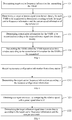
- FIG. 2 is a flowchart illustrating a method of transmitting a reference signal according to an exemplary embodiment of the present disclosure.
- the method is applicable to vehicle user equipment (UE), and includes following steps: In step 11, transmission configuration information of a synchronization signal block (VSSB) in a new radio-vehicle-to-everything (NR-V2X) system is determined.
- the transmission configuration information includes: a transmission period of the VSSB and a time domain position of a VSSB transmission time window within the transmission period.
- each VSSB includes: a primary sidelink synchronization signal (PSSS), a secondary sidelink synchronization signal (SSSS), a physical sidelink broadcast channel (PSBCH) signal, and a demodulation reference signal (DMRS).
- PSSS primary sidelink synchronization signal
- SSSS secondary sidelink synchronization signal
- PSBCH physical sidelink broadcast channel
- DMRS demodulation reference signal
- N VSSBs are transmitted within a VSSB transmission time window which occurs periodically, where N is an integer greater than or equal to 1.
- a VSSB transmission time window is set at a fixed position of each transmission period in the present disclosure. For example, a transmission window with a duration of 5 ms is set at the 50 ms position of 160 ms, and a position of the VSSB transmission time window within the SVVB transmission window may be expressed as 50 ms ⁇ 54 ms.
- the vehicle-borne device in response to that a VSSB transmission time window arrives, transmits N VSSBs though a beam.
- vehicle UE may predict a possible Doppler frequency shift based on speed information of the vehicle UE, and then changes a reference signal time domain density for the VSSBs to counteract the Doppler shift effect, thereby guaranteeing that the VSSB transmitted by the vehicle-borne device can be detected by a receiving terminal.
- the step 12 may include:
- the vehicle UE may determine the target carrier frequency information for transmitting the VSSBs in any one of: Manner 1: determining the target carrier frequency information according to preset resource configuration information.
- carrier frequency information for transmitting VSSB is pre-stored in a chip of the vehicle UE, and the vehicle UE may directly read target carrier frequency information from the chip.
- the foregoing step 121 may include:
- step 1211 resource configuration information is received from a base station, where the resource configuration information is configured to instruct the vehicle-borne device to transmit the VSSB with configured resource.
- VSSB is transmitted with preset resources configured by the base station.
- resource blocks that the base station configures for the vehicle UE is located at a same carrier frequency as resources used by the base station, then, the resource configuration information does not need to indicate any carrier frequency band information, but only indicates position information of a resource block (RB).
- RB resource block
- the resource configuration information is required to indicate both carrier frequency band information and resource block position information.
- the target carrier frequency information is determined according to the resource configuration information.
- the current working carrier frequency for communicating with the base station is determined as the above target carrier frequency for transmitting VSSB.
- the vehicle UE determines the target carrier frequency according to the carrier frequency band information notified by the base station.
- the frequency band of the carrier frequency configured by the system for transmitting VSSB may include: frequency bands below 3 GHz, 3 GHz-6 GHz, and above 6 GHz.
- a target reference signal time domain density for each VSSB to be transmitted is determined according to both the target carrier frequency information and the current speed information of the vehicle UE.
- the reference signal time domain density may be expressed as a ratio of the total number of symbols occupied by the reference signal to a duration occupied a VSSB, wherein the reference signal includes: a primary sidelink synchronization signal (PSSS), a secondary sidelink synchronization signal (SSSS) and a demodulation reference signal (DMRS).
- PSSS primary sidelink synchronization signal
- SSSS secondary sidelink synchronization signal
- DMRS demodulation reference signal
- the current speed information of the vehicle UE may include: a current speed of the vehicle where the vehicle UE is located; or, a relative speed between the vehicle UE and a target receiving terminal.
- the Doppler frequency shift may be estimated according to the current speed information, and then the reference signal time domain density for the VSSB is adjusted so as to counteract the Doppler frequency effect.
- the foregoing step 122 may include:
- time domain density levels may be used to indicate reference signal time domain densities with different magnitudes, and the higher the level, the greater corresponding reference signal time domain density.
- a preset number of reference signal time domain density levels may be agreed in the protocol, and each time domain density level corresponds to a preset speed matching condition.
- a correspondence between the time domain density level and the preset speed matching condition may be determined according to the protocol.
- V10 and V20 are set in the system, wherein V10 is less than V20; and the two speed thresholds correspond to different reference signal time domain density levels, respectively.
- Table I Speed matching condition Time domain density level V ⁇ V10 First level V10 ⁇ V ⁇ V20 second level V >V20 Third level
- the vehicle UE may compare the currently determined relative speed with the respective speed thresholds as illustrated in Table I to determine which speed matching condition the current relative speed falls into, and thus determine a required reference signal time domain density level.
- transmission information for the VSSB to be transmitted is determined according to the target reference signal time domain density.
- the transmission information includes: a target subcarrier spacing for transmitting the VSSB and a structure of the VSSBs to be transmitted.
- the structure of VSSBs to be transmitted comprises: a number of symbols occupied by each signal and positions of the symbols occupied;
- a reference signal time domain density level for a VSSB is related to both the subcarrier spacing for transmitting the VSSB and the total number of time domain units such as symbols occupied by the reference signal in a signal structure of the VSSB.
- the subcarrier spacings that the system may use to transmit VSSBs include: 15 KHz, 30 KHz, and 60 KHz.
- the sub-carrier spacings that the system may use to transmit VSSBs include: 120 KHz, 240 KHz, and 480 KHz. The higher the frequency band to which the target carrier frequency of the vehicle UE belongs, the greater the sub-carrier spacing for transmitting VSSBs.
- a subcarrier spacing that may be used in a case that the target carrier frequency is 6 GHz should be greater than or equal to a subcarrier spacing that may be used in a case that the target carrier frequency is 3 GHz.
- 15 KHz or 30 KHz may be used at 3 GHz
- 30 KHz or 60 KHz may be used at 6 GHz.
- the target carrier frequency determined in step 121 above being 3 GHz frequency band as an example, supposing that it is agreed in the system that an available subcarrier spacing for the 3 GHz frequency band includes: 15 KHz and 30 KHz; and meanwhile, it is also agreed in the system that two VSSB structures, which are expressed as a first VSSB structure and a second VSSB, may be used in this frequency band, wherein a symbol ratio of a reference signal in the second VSSB structure is greater than a symbol ratio of a reference signal in the first VSSB structure.
- Table II Subcarrier Spacing VSSB Structure Time domain density level 15 KHz First VSSB structure First level Second VSSB structure second level 30 KHz First VSSB structure Second VSSB structure Third level
- the vehicle UE determines that it is necessary to increase the reference signal time domain density level for the VSSB to be transmitted from the first level to the second level according to a current relative speed.
- a VSSB structure used by the vehicle UE before adjusting the reference signal time domain density may be referred to as an original VSSB structure.
- the adopted subcarrier spacing is 15 KHz.
- a VSSB is provided in a time slot, and is supposed that an original VSSB structure used by the vehicle-borne device is the first VSSB structure.
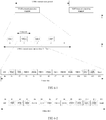
- the first VSSB structure used by the vehicle UE may be as illustrated in Figure 6-1 , where the number of symbols occupied by PSSS is 2, the number of symbols occupied by SSSS is 2, the number of symbols occupied by PSBCH is 5, and the number of symbols occupied by DMRS.
- the number of symbols is 3.
- the vehicle UE may increase the reference signal time domain density for the VSSB to be transmitted to the second level through at least one of: Manner 1: the second VSSB structure with a larger reference signal is adopted without changing the used subcarrier spacing.
- the second VSSB structure in the present disclosure may be designed in any one of:
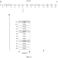
- the number of symbols occupied by at least one reference signal is increased and the number of symbols occupied by PSBCH is reduced in a case that a duration of the VSSB remains unchanged.
- the number of symbols occupied by PSSS is 3
- the number of symbols occupied by SSSS is 3
- the number of symbols occupied by PSBCH is 2
- the number of symbols occupied by DMRS is 4.
- the number of symbols occupied by DMRS is increased in a FDM manner in a case that a duration of the VSSB remains unchanged.
- a portion of resource blocks corresponding to the symbols occupied by each or part of the PSBCHs, such as #3, #5, #7, #8, #10, are allocated to carry DMRSs, as illustrated in FIG. 6-3 , thereby increasing the number of symbols occupied by DMRS.
- the proportion of reference signals is increased, that is, a ratio of the number of the symbols occupied by reference signals to the duration of the VSSB, thereby increasing the reference signal time domain density.
- the reference signal time domain density for the VSSB may be increased by increasing the subcarrier spacing.
- VSSB transmission time window of 5 ms includes 5 time slots.
- VSSB0, VSSB1, VSSB2, and VSSB3 respectively represent index information of each VSSB to be transmitted.
- 1 ms corresponds to 2 time slots, that is, a duration of 1 time slot is shortened to 0.5 ms. Since position and the number of symbols occupied by VSSB in a time slot remain unchanged, a duration of a single VSSB is reduced to half of the time illustrated in FIG. 6-1 , as illustrated in FIG. 6-4 , where V0, V1, V2, and V3 represent index information of each VSSB, which is same to VSSB0, VSSB1, VSSB2, and VSSB3 as illustrated in FIG. 6-1 .
- the ratio of the number of symbols occupied by the reference signal in VSSB to a duration occupied by the VSSB becomes larger, so as to increase the reference signal time domain density by increasing the target subcarrier spacing, thereby counteracting greater Doppler frequency shift.
- both the target subcarrier spacing and the target VSSB structure required by the target reference signal time domain density are determined, that is, transmission information for a single VSSB to be transmitted is determined.
- the vehicle UE may adjust in time the reference signal time domain density for the VSSB to be transmitted through at least one of the above methods, thereby effectively counteracting Doppler shift and ensuring instant communication between the vehicle-mounted equipment and a receiving terminal.
- step 124 the VSSB is transmitted within the VSSB transmission time window according to the transmission information for the VSSB to be transmitted.
- the vehicle UE in a case that the vehicle UE transmits an VSSB to a receiving terminal within the VSSB transmission time window, it also needs to carry index information of occupied effective unit time domain resources, so that the receiving terminal may perform a time domain synchronization with the vehicle UE according to the index information.
- the step 12 may include:
- the index information of the VSSB to be transmitted may be loaded into the setting signal of the VSSB to be transmitted through any of: Manner 1: the index information of the VSSB to be transmitted may be indicated by a corresponding DMRS target sequence;
- index information DMRS sequence VSSB 0 * VSSB 1 ** VSSB 2 *** VSSB 3 ****
- the vehicle UE may load the sequence "****" corresponding to VSSB3 into the DMRS of the VSSB.
- the above index information VSSB 3 is indicated by the DMRS sequence "****”.
- Manner 2 index information of the VSSB to be transmitted is loaded into a first bit of a PSBCH signal.
- the index information can be loaded into a reserved information bit or a new information bit of the PSBCH signal, which is referred to as the first bit in the present disclosure.
- the bit value 11 of the VSSB 3 is set in the 2 reserved bits or new bits of the PSBCH signal to indicate the index information.
- Manner 3 Indicating a part of bit values of the index information of the VSSB to be transmitted by a corresponding DMRS target sequence, and loading remaining of the bit values into a second bit of the PSBCH signal.
- the index information may further be indicated by a combination of a DMRS target sequence and bit information set in the PSBCH signal.
- bit values of the index information VSSB 3 are 11.
- the bit value of the lower bit “ 1" may be indicated by the preset DMRS target sequence such as "*”, and the bit value of the higher bit "1" is placed in a reserved bit or a new bit of the PSBCH signal.
- the reserved bit or the new bit of the PSBCH signal which is used to carry partial index information is referred to as the second bit.
- a bit value of a higher bit of the index information is indicated by a DMRS target sequence, and correspondingly, a remaining bit value is indicated by the second bit of the PSBCH signal, which is not limited in the present disclosure.
- VSSB which carries VSSB index information
- target VSSB a VSSB which carries VSSB index information
- step 1202 the target VSSB is transmitted through a plurality of beams within the VSSB transmission time window that occurs periodically.
- a beam is used to transmit the target VSSB in different directions at different times. For example, in the example as illustrated in FIG. 6-1 , at a time domain position corresponding to a first time slot VSSB0 of 5 ms, a beam is used to transmit the target VSSB carrying index information VSSB 0 in one direction. And at a time domain position corresponding to a third time slot VSSB 2, a beam is used to transmit the target VSSB carrying the index information VSSB 2 in another direction; and so on.
- the present disclosure may propose the following three transmission modes: In a first transmission mode, a PSBCH signal and a DMRS of a VSSB are transmitted in Time Division Multiplexing (TDM) mode, that is, the PSBCH signal and the DMRS are transmitted in time-frequency resources corresponding to different symbols. In this mode, frequency domains of the PSBCH signal and the DMRS may be the same, but the time domains of the PSBCH signal and the DMRS are different.
- TDM Time Division Multiplexing
- a PSBCH signal and a DMRS of a VSSB are transmitted in Frequency Division Multiplexing (FDM) mode, that is, the PSBCH signal and the DMRS may be transmitted in different frequency domain resources corresponding to a same symbol.
- FDM Frequency Division Multiplexing
- the time domain of the PSBCH signal and the DMRS may be the same, but the frequency domains of the PSBCH signal and the DMRS are different.
- the PSBCH signal and the DMRS are transmitted in a combined manner of TDM and FDM.
- TDM and FDM time-frequency resources corresponding to a symbol occupied by the PSBCH signal such as symbol #5
- some resources such as RE#3, RE#7 , RE#11 of twelve Resource Elements (RE) included in an RB
- RE Resource Elements
- the DMRS is also transmitted in time-frequency resource corresponding to symbol #6.
- a proportion of REs occupied by DMRS may be 1/3 or 1/4, and the like.
- the base station may transmit the above-mentioned resource configuration information to the vehicle UE and the receiving terminal through a broadcast signaling, a high-level signaling, and a physical layer signaling.
- the high-level signaling may be a Radio Resource Control (RRC) signaling, a Medium Access Control (MAC) Control Element (CE) signaling, and the like.
- RRC Radio Resource Control
- MAC Medium Access Control
- CE Control Element
- Vehicle user equipment may transmit a reference signal via a synchronization signal block VSSB structure to receiving terminals in different directions through beams within a VSSB transmission time window that occurs periodically, so that a receiving terminal may perform, after receiving the VSSB from the vehicle UE, a time domain synchronization with the vehicle UE quickly by using a reference signal for the VSSB and index information carried by the VSSB, thereby improving efficiency of time domain synchronization between the receiving terminal and the vehicle UE, reducing time for signal synchronization, and ensuring immediacy of communication between the vehicle equipment and the receiving terminal.
- embodiments of the present disclosure further provides a method of receiving a reference signal, which is applicable to a receiving terminal of an NR-V2X system.
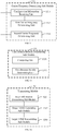
- FIG. 8 is a flowchart illustrating a method of receiving a reference signal according to an exemplary embodiment, the method may include:
- the step 21 may include:
- step 211 resource configuration information is received from a base station, wherein the resource configuration information is configured to instruct the receiving terminal to receive the VSSB with configured resource.
- step 212 target carrier frequency information for receiving the VSSB is determined according to the resource configuration information.
- the base station may further transmit resource configuration information to the receiving terminal to inform the receiving terminal which carrier frequency the VSSB transmitted from the vehicle UE is received.
- step 213 detecting subcarrier spacing is determined according to the target carrier frequency information.
- the receiving terminal determines that the carrier frequency for receiving VSSB is the carrier frequency of the 3 GHz band. It is provided in the protocol of the system that the carrier frequency of a frequency band can be used with one or more subcarrier spacings, and the receiving terminal may determine each of the available subcarrier spacings as a detecting subcarrier spacing.
- the detecting subcarrier spacing corresponding to the 3GHz frequency band may include: 15 KHz, and 30 KHz.
- step 214 the VSSB is detected at the target resource with each of the detecting subcarrier spacings.
- the receiving terminal may use 15 KHz and 30 KHz to detect a VSSB, and a detecting subcarrier spacing used in a case that VSSB is detected is determined as a target subcarrier spacing, such as 15 KHz.
- VSSB index information is obtained from a target VSSB detected.
- the step 22 may include:
- the setting signal may comprise a preset PSBCH signal of the target VSSB, a preset DMRS of the target VSSB, or a combination thereof.
- the receiving terminal may obtain the VSSB index information from the setting signal of the target VSSB in any one of:
- step 1201 exemplarily, in a case that it is detected that information bit value of a preset bit of the preset PSBCH signal of the target VSSB, that is, a first bit, is 11, it is determined that VSSB index information carried by the target VSSB is VSSB 3.
- the step 222 may include:
- step 1201 in a case that a bit value of the DMRS sequence carried by the preset DMRS of the target VSSB is 1, the bit value obtained from the second bit of the preset PSBCH signal of the target VSSB is 1.
- the DMRS sequence carried by the preset DMRS indicates a high bit value of the bit values of the VSSB index information and a value of the second bit of the preset PSBCH signal indicates a lower bit value of the bit values of the VSSB index information
- step 23 a time domain position of the target VSSB is determined according to the VSSB index information
- the receiving terminal determines the time domain position of the target VSSB according to the VSSB index information, the target carrier frequency information, and the target subcarrier spacing. Still taking the target carrier frequency of 3G Hz, target subcarrier spacing of 15 KHz, and VSSB index information of VSSB 3 as an example, according to FIG. 5-1 , the exact time domain position of the target VSSB within the transmitting time window may be determined, that is, the #1 ⁇ #12 symbols in a fourth time slot in the VSSB transmission time window, i.e., a slot numbered 3.
- step 24 a time domain synchronization is performed with the vehicle UE according to the time domain position.
- the present disclosure further provides device embodiments and apparatus embodiments for achieving corresponding application functions.
- the present disclosure provides a device for transmitting a reference signal, which can be provided on vehicle user equipment (UE).
- UE vehicle user equipment
- FIG. 12 is a block diagram illustrating a device for transmitting a reference signal according to an exemplary embodiment, the device may include:
- the transmitting module 32 may include:
- the carrier frequency determining sub-module 321 may include:
- the time domain density determining sub-module 322 may include:
- the time domain density determining unit 3222 may be configured to increase the reference signal time domain density at the target carrier frequency to a target reference signal time domain density corresponding to the comparison result in response to the comparison result indicating that the relative speed is greater than or equal to the preset speed threshold.
- the time domain density determining unit 3222 may be configured to increase the reference signal time domain density at the target carrier frequency to the target reference signal time domain density corresponding to the comparison result through at least one of:
- the transmitting module 32 may include:
- the target VSSB generating sub-module 3202 may be configured to load the VSSB index information into a preset signal of the VSSB to be transmitted in any one:
- a target VSSB transmitting sub-module 3203 is configured to transmit the target VSSB through a plurality of beams within the VSSB transmission time window that occurs periodically.
- the transmitting module 32 may be configured to transmit the PSBCH signal and the DMRS of each of the VSSBs through at least one of a frequency division multiplexing (FDM) manner and a time division multiplexing (TDM) manner.
- FDM frequency division multiplexing
- TDM time division multiplexing
- the present disclosure further provides a device for receiving a reference signal, which is provided in a receiving terminal.
- a device for receiving a reference signal which is provided in a receiving terminal.
- the device may include:
- the detecting module 41 may include:
- the index information obtaining module 42 may include:
- the index information obtaining sub-module 422 may include:
- the index information acquiring sub-module includes:
- the position determining module may be configured to determine a time domain position of the target VSSB according to the VSSB index information, the target carrier frequency information, and the target subcarrier spacing; wherein the target subcarrier spacing indicates a detecting subcarrier spacing used to detect the target VSSB.
- the device embodiment since it substantially corresponds to the method embodiment, relevant parts may be referred to the part of the description of the method embodiment.
- the device embodiments described above are merely illustrative.
- the units described above as separate components may or may not be physically separated, and the components displayed as units may or may not be physical units, that is, they may be located at a position, or they may be distributed over multiple network units.
- Some or all of the modules may be selected according to actual requirement to achieve the objectives of the solutions of the present disclosure.
- One of ordinary skill in the art can understand and implement it without any creative works.
- vehicle user equipment including:
- a terminal including:
- a base station 2200 includes a processing component 2222, a wireless transmitting/receiving component 2224, an antenna component 2226, and a signal processing part specific to a wireless interface.
- the processing component 2222 may further include one or more processors.
- One processor of the processing component 2222 may be configured to:
- a non-transitory computer-readable storage medium on which computer instructions are stored.
- the computer instructions can be executed by a processing component 2222 of vehicle user equipment (UE) 2200 to implement operations of any method of transmitting a reference signal as illustrated in FIGS. 2-7 .
- the non-transitory computer-readable storage medium may be ROM, random access memory (RAM), CD-ROM, magnetic tape, floppy disk, optical data storage device, etc.
- FIG. 23 is a schematic structural diagram illustrating a terminal 2300 according to an exemplary embodiment.
- the terminal 2300 may be user equipment, which may specifically be a mobile phone, a computer, a digital broadcasting terminal, a messaging device, a game console, a tablet device, a medical device, a fitness device, a personal digital assistant, and wearable devices such as smart watches and smart glasses, smart bracelets, smart running shoes, etc.
- the terminal 2300 may include one or more of the following components: a processing component 2302, a memory 2304, a power supply component 2306, a multimedia component 2308, an audio component 2310, an input/output (I/O) interface 2312, a sensor component 2314, and a communication component 2316.
- the processing component 2302 generally controls overall operations of the terminal 2300, such as operations associated with display, telephone calls, data communication, camera operations, and recording operations.
- the processing component 2302 may include one or more processors 2320 to execute instructions to perform all or part of the steps of any one of the methods as described above.
- the processing component 2302 may include one or more modules to facilitate interaction between the processing component 2302 and other components.
- the processing component 2302 may include a multimedia module to facilitate interaction between the multimedia component 2308 and the processing component 2302.
- the memory 230 is configured to store various types of data to support operations on the terminal 2300. Examples of these data include instructions for any application or method operated on the terminal 2300, contact data, phone book data, messages, pictures, videos, etc.
- the memory 2304 can be implemented by any type of volatile or non-volatile storage device or their combination, such as static random access memory (SRAM), electrically erasable programmable read-only memory (EEPROM), erasable programmable read-only memory (EPROM), programmable read-only memory (PROM), read-only memory (ROM), magnetic memory, flash memory, magnetic disk or optical disk.
- SRAM static random access memory
- EEPROM electrically erasable programmable read-only memory
- EPROM erasable programmable read-only memory
- PROM programmable read-only memory
- ROM read-only memory
- magnetic memory flash memory
- flash memory magnetic disk or optical disk.
- the power supply component 2306 provides power for respective components of the terminal 2300.
- the power supply component 2306 may include a power management system, one or more power supplies, and other components associated with the generation, management, and distribution of power for the terminal 2300.
- the multimedia component 2308 includes a screen providing an output interface between the terminal 2300 and a user.
- the screen may include a liquid crystal display (LCD) and a touch panel (TP).
- the screen may be implemented as a touch screen to receive input signals from the user.
- the touch panel includes one or more touch sensors to sense touch, sliding, and gestures on the touch panel. The touch sensor can not only sense the boundary of the touch or sliding operation, but also detect a duration and a pressure related to the touch or sliding operation.
- the multimedia component 2308 includes a front camera and/or a rear camera.
- the front camera and/or the rear camera can receive external multimedia data.
- the front camera and the rear camera may be a fixed optical lens system or have a focal length with optical zooming capabilities.
- the audio component 2310 is configured to output and/or input audio signals.
- the audio component 2310 includes a microphone (MIC).
- the microphone is configured to receive external audio signals.
- the received audio signal may be further stored in the memory 2304 or transmitted via the communication component 2316.
- the audio component 2310 further includes a speaker for outputting audio signals.
- the I/O interface 2312 provides an interface between the processing component 2302 and the peripheral interface module.
- the peripheral interface module may be a keyboard, a click wheel, buttons, and the like.
- the buttons may include but are not limited to: a home button, a volume button, a start button, and a locking button.
- the sensor component 2314 includes one or more sensors for providing the terminal 2300 with status evaluation of various aspects.
- the sensor component 2314 can detect the ON/OFF status of the device 2300 and relative positioning of the components.
- the components are a display and a keypad of the terminal 2300.
- the sensor component 2314 can also detect the position change of the terminal 2300 or a component of the terminal 2300. The presence or absence of contact between the user and the terminal 2300, the orientation or acceleration/deceleration of the terminal 2300, and the temperature change of the terminal 2300.
- the sensor assembly 2314 may include a proximity sensor configured to detect presence of nearby objects in a case that there is no physical contact.
- the sensor component 2314 may further include a light sensor, such as a CMOS or CCD image sensor, for imaging applications.
- the sensor component 2314 may further include an acceleration sensor, a gyroscope sensor, a magnetic sensor, a pressure sensor or a temperature sensor.
- the communication component 2316 is configured to facilitate wired or wireless communication between the terminal 2300 and other devices.
- the terminal 2300 may access a wireless network based on a communication standard, such as WiFi, 2G, 3G, 4G LTE, 5G NR, or a combination thereof.
- the communication component 2316 receives a broadcast signal or broadcast related information from an external broadcast management system via a broadcast channel.
- the communication component 2316 further includes a near field communication (NFC) module to facilitate short-range communication.
- the NFC module may be implemented based on radio frequency identification (RFID) technology, infrared data association (IrDA) technology, ultra-wideband (UWB) technology, Bluetooth (BT) technology and other technologies.
- RFID radio frequency identification
- IrDA infrared data association
- UWB ultra-wideband
- Bluetooth Bluetooth
- the terminal 2300 may be implemented by one or more application specific integrated circuits (ASIC), digital signal processors (DSP), digital signal processing devices (DSPD), programmable logic devices (PLD), field programmable gate arrays (FPGA), controllers, microcontrollers, microprocessors, or other electronic components, and is configured to perform any one of the methods as described above.
- ASIC application specific integrated circuits
- DSP digital signal processors
- DSPD digital signal processing devices
- PLD programmable logic devices
- FPGA field programmable gate arrays
- controllers microcontrollers, microprocessors, or other electronic components, and is configured to perform any one of the methods as described above.
- a non-transitory computer-readable storage medium including instructions, such as a memory 2304 including instructions, which may be executed by the processor 2320 of the terminal 2300 to implement operations of any of the methods of receiving a reference signal as illustrated in FIGS. 8-11 .
- the non-transitory computer-readable storage medium may be ROM, random access memory (RAM), CD-ROM, magnetic tape, floppy disk, optical data storage device, etc.
Landscapes
- Engineering & Computer Science (AREA)
- Signal Processing (AREA)
- Computer Networks & Wireless Communication (AREA)
- Quality & Reliability (AREA)
- Databases & Information Systems (AREA)
- Computer Security & Cryptography (AREA)
- Physics & Mathematics (AREA)
- Mathematical Physics (AREA)
- Mobile Radio Communication Systems (AREA)
- Traffic Control Systems (AREA)
Abstract
Description
- The present disclosure relates to the field of communication technology, and in particular, to methods, devices, vehicle user equipment (UE), and terminals of transmitting and receiving a reference signal.
- In the LTE Vehicle-to-Everything (V2X) technology, for example, in an application scenario of Vehicle-to-Vehicle (V2V) communication, due to the possibility of two vehicles meeting each other, the speed of one vehicle with respect to another vehicle is almost two times of its own speed, which makes the Doppler shift larger. To counteract relatively large Doppler shift, in a subframe of 1ms, each of a Primary Sidelink Synchronization Signal (PSSS) and a Secondary Sidelink Synchronization Signal (SSSS) of V2X occupies two symbols, and a Physical Sidelink Broadcast Channel (PSBCH) occupies 5 symbols, and among them, 3 symbols of Demodulation Reference Signal (DMRS) are transmitted in a manner of time division to demodulate the PSBCH. In addition, a subframe of 1 ms contains two slots, each of which contains 7 symbols. Among these 14 symbols, the first symbol is used for Automatic Gain Control (AGC), that is, for adjusting power gain of a device to receive PSSS/SSSS/PSBCH, and the last symbol is used to counteract transmission and reception delay caused by devices at different positions. And a period for transmitting the synchronization signal and the broadcast channel is 160 ms, that is, 1 ms of every 160 ms is used to transmit a frame structure of synchronization signal and broadcast channel. In addition, because the LTE sidelink has a feature similar to LTE uplink and Single-carrier Frequency-Division Multiple Access (SC-FDMA) is used in the uplink, the DMRS and the PSBCH are transmitted at different symbols.
- On the spectrum of the New Radio (NR) Access technology, each time slot (slot) includes 14 symbols, and how many slots are contained in 1 millisecond (ms) is determined by a subcarrier spacing. For example, in a case that the subcarrier spacing is 15 kilohertz (KHz), there is 1 slot in 1 ms; in a case that the subcarrier spacing is 30 KHz, there are 2 slots in 1ms; and in a case that the subcarrier spacing is 60KHz, there are 4 slots in 1ms, and so on.
- In the NR, in order to reduce the always-on reference signal and thereby reduce the overhead, a Synchronization Signal Block (SSB) is proposed. Each SSB occupies 4 consecutive symbols, which are, in sequence, a Primary Synchronization Signal (PSS), a Physical Broadcast Channel (PBCH), a Secondary Synchronization Signal (SSS) and a PBCH, respectively, wherein, 12 resource blocks (RB) in a symbol in which the SSB is located are the SSS, and 4 RBs on respective sides are the PBCH, and some subcarriers in the PBCH are Demodulation Reference Signals (DMRS). A subcarrier spacing of the synchronization signal block may be 15 KHz, 30 KHz, 120 KHz and 240 KHz. All synchronization signal blocks are transmitted within 5 ms. In order to support beam transmission, in a case that there are beams, each beam needs to transmit SSBs, so the maximum number of synchronization signal blocks that can be transmitted within 5 ms is 4 (in a case that the carrier frequency is below 3GHz) or 8 (in a case that the carrier frequency is 3 GHz∼6 GHz) or 64 (in a case that the carrier frequency is above 6GHz), and the plurality of SSBs within 5 ms are referred to as an SSB burst set. A period for transmitting an SSB burst set may be 5 ms, 10 ms, 20 ms, 40 ms, and etc.
- V2X technology has further been introduced into a 5G NR system, but transmission of synchronization signals and broadcast channels has not been defined yet.
- In order to overcome the problems in the related arts, embodiments of the present disclosure provide methods, devices, vehicle user equipment (UE), and terminals of transmitting and receiving a reference signal, wherein transmission characteristics of VSSBs may be dynamically changed so as to effectively counteract Doppler shift effect occurring between the vehicle UE and the receiving terminal.
- According to a first aspect of the present disclosure, there is provided a method of transmitting a reference signal, including:
- determining transmission configuration information of a synchronization signal block (VSSB) in a new radio-vehicle-to-everything (NR-V2X) system, the transmission configuration information including: a transmission period of the VSSB, and a time domain position of a VSSB transmission time window within the transmission period;
- transmitting N VSSBs within the VSSB transmission time window that occurs periodically according to the transmission configuration information, where N is an integer greater than or equal to 1;
- wherein each of the VSSBs includes a primary sidelink synchronization signal (PSSS), a secondary sidelink synchronization signal (SSSS), a physical sidelink broadcast channel (PSBCH) signal, and a demodulation reference signal (DMRS).
- In some embodiments of the present disclosure, transmitting the N VSSBs within the VSSB transmission time window that occurs periodically includes: for each of VSSB to be transmitted,
determining target carrier frequency information for transmitting the VSSB;
determining, according to both the target carrier frequency information and current speed information of vehicle user equipment (UE), a target reference signal time domain density for the VSSB to be transmitted;
determining transmission information for the VSSB to be transmitted according to the target reference signal time domain density, wherein the transmission information includes: a target subcarrier spacing for transmitting the VSSB and a structure of the VSSB to be transmitted, and the structure of the VSSB to be transmitted comprises a number and a position of symbols occupied by respective signals; and
transmitting, according to the transmission information for the VSSB to be transmitted, the VSSB within the VSSB transmission time window. - In some embodiments of the present disclosure, determining the target carrier frequency information for transmitting the VSSB includes:
- receiving resource configuration information from the base station, wherein the resource configuration information is configured to instruct the vehicle UE to transmit the VSSB with configured resource;
- determining the target carrier frequency information according to the resource configuration information; or,
- determining the target carrier frequency information according to preset resource configuration information.
- In some embodiments of the present disclosure, the current speed information includes: a relative speed between the vehicle UE and a preset receiving terminal;
Determining, according to the target carrier frequency information and the current speed information of the vehicle UE, the target reference signal time domain density for each VSSB to be transmitted includes: - obtaining a comparison result by comparing the relative speed with a preset speed threshold; and
- determining the target reference signal time domain density according to the target carrier frequency information and the comparison result.
- In some embodiments of the present disclosure, determining the target reference signal time domain density according to both the target carrier frequency information and the comparison result includes:
in response to the comparison result indicating that the relative speed is greater than or equal to the preset speed threshold, increasing a reference signal time domain density at the target carrier frequency to a target reference signal time domain density corresponding to the comparison result. - In some embodiments of the present disclosure, increasing a reference signal time domain density at the target carrier frequency to the target reference signal time domain density corresponding to the comparison result is implemented through at least one of:
- using a target VSSB structure, wherein a reference signal proportion in the target VSSB structure is greater than a reference signal proportion in an original VSSB structure, and the reference signal proportion is a ratio of a number of symbols occupied by the reference signal with respect to a duration occupied by the VSSB; and/or
- increasing a subcarrier spacing for transmitting VSSB at the target carrier frequency.
- In some embodiments of the present disclosure, transmitting the N VSSBs within the VSSB transmission time window that occurs periodically includes:
- in response to N greater than 1, determining a VSSB index information for each VSSB;
- generating a target VSSB carrying the index information by loading the VSSB index information into a setting signal of the VSSB to be transmitted; and
- transmitting the target VSSB through a plurality of beams in the VSSB transmission time window that occurs periodically.
- In some embodiments of the present disclosure, loading the VSSB index information into the setting signal of the VSSB to be transmitted is implemented through any one of:
- indicating the VSSB index information by a corresponding DMRS target sequence;
- loading the VSSB index information into a first bit of the PSBCH signal; and
- indicating a part of bit values of the VSSB index information by the corresponding DMRS target sequence, and loading remaining of the bit values into a second bit of the PSBCH signal.
- In some embodiments of the present disclosure, transmitting the N VSSBs within the VSSB transmission time window that occurs periodically includes:
transmitting the PSBCH signal and the DMRS of each of the VSSBs in at least one of a frequency division multiplexing (FDM) manner and a time division multiplexing (TDM) manner. - According to a second aspect of the present disclosure, a method of receiving a reference signal is provided, including:
- detecting a synchronization signal block (VSSB) in a new radio-vehicle-to-everything (NR-V2X) system transmitted from vehicle user equipment (UE);
- obtaining VSSB index information from a target VSSB detected;
- determining a time domain position of the target VSSB according to the VSSB index information; and
- performing a time domain synchronization with the vehicle UE according to the time domain position.
- In some embodiments of the present disclosure, detecting the VSSB transmitted from the vehicle UE includes:
- receiving resource configuration information from a base station, wherein the resource configuration information is configured to instruct the receiving terminal to receive the VSSB through configured resource;
- determining, according to the resource configuration information, target carrier frequency information for receiving the VSSB;
- determining a detecting subcarrier spacing according to the target carrier frequency information; and
- detecting the VSSB at a target frequency band with each detecting subcarrier spacing.
- In some embodiments of the present disclosure, obtaining the VSSB index information from the detected target VSSB includes:
- obtaining respective signals by analyzing the target VSSB, the respective signals including: a primary sidelink synchronization signal (PSSS), a secondary sidelink synchronization signal (SSSS), a physical sidelink broadcast channel (PSBCH) signal, and a demodulation reference signal (DMRS); and
- obtaining the VSSB index information from a setting signal, wherein the setting signal includes at least one of the PSBCH signal and the DMRS.
- In some embodiments of the present disclosure, obtaining the VSSB index information from the setting signal includes any one of:
- obtaining the VSSB index information from information carried by the setting DMRS sequence; and
- obtaining the VSSB index by analyzing a bit of the setting PSBCH signal.
- In some embodiments of the present disclosure, obtaining the VSSB index information from the setting signal includes:
- obtaining a part of bit values of the VSSB index information from information carried by the setting DMRS sequence;
- obtaining remaining of the bit values of the VSSB index information from a bit of the setting PSBCH signal; and
- determining the VSSB index information according to complete bit values composed of the part of the bit values and the remaining of the bit values.
- In some embodiments of the present disclosure, determining the time domain position of the VSSB according to the VSSB index information includes:
determining the time domain position of the target VSSB according to the VSSB index information, the target carrier frequency information, and the target subcarrier spacing; wherein the target subcarrier spacing indicates a detecting subcarrier spacing used to detect the target VSSB. - According to a third aspect of the present disclosure, a device for transmitting a reference signal is provided, including:
- a configuration information determining module, configured to determine transmission configuration information of a synchronization signal block (VSSB) in a new radio-vehicle-to-everything (NR-V2X) system, the transmission configuration information including a transmission period of the VSSB, and a time domain position of a VSSB transmission time window within the transmission period; and
- a transmitting module, configured to transmit N VSSBs within a VSSB transmission time window that occurs periodically according to the transmission configuration information, where N is an integer greater than or equal to 1;
- wherein each of the N VSSBs includes a primary sidelink synchronization signal (PSSS), a secondary sidelink synchronization signal (SSSS), a physical sidelink broadcast channel (PSBCH) signal, and a demodulation reference signal (DMRS).
- In some embodiments of the present disclosure, the transmitting module includes:
- a carrier frequency determining sub-module, configured to determine target carrier frequency information for transmitting the VSSBs;
- a time domain density determining sub-module, configured to determine a target reference signal time domain density for each of the VSSBs to be transmitted according to both the target carrier frequency information and a current speed information of vehicle user equipment (UE);
- a transmission information determining sub-module, configured to determine transmission information for the VSSBs to be transmitted according to the target reference signal time domain density, the transmission information including a target subcarrier spacing for transmitting the VSSBs and a structure of the VSSBs to be transmitted, wherein the structure of the VSSBs to be transmitted comprises a number of symbols occupied by each signal and positions of the occupied symbols; and
- a transmitting sub-module, configured to transmit the VSSBs according to the transmission information for the VSSBs to be transmitted within the VSSB transmission time window.
- In some embodiments of the present disclosure, the carrier frequency determining sub-module includes:
- a configuration information receiving unit, configured to receive resource configuration information from a base station, where the resource configuration information is configured to instruct the vehicle UE to transmit the VSSB with configured resource;
- a first carrier frequency determining unit, configured to determine target carrier frequency information according to the resource configuration information; or,
- a second carrier frequency determining unit, configured to determine the target carrier frequency information according to preset resource configuration information.
- In some embodiments of the present disclosure, the current speed information includes: a relative speed between the vehicle UE and a preset receiving terminal;
the time domain density determining sub-module includes: - a comparing unit, configured to obtain a comparison result by comparing the relative speed with a preset speed threshold; and
- a time domain density determining unit, configured to determine the target reference signal time domain density according to both the target carrier frequency information and the comparison result.
- In some embodiments of the present disclosure, the time domain density determining unit is configured to increase a target reference signal time domain density at a target carrier frequency to a target reference signal time domain density corresponding to the comparison result in response to the comparison result indicating the relative speed is greater than or equal to the preset speed threshold.
- In some embodiments of the present disclosure, the time domain density determining unit is configured to increase a target reference signal time domain density at the target carrier frequency to a target reference signal time domain density corresponding to the comparison result through at least one of:
- using a target VSSB structure, wherein the reference signal proportion of the target VSSB structure is greater than a reference signal proportion of an original VSSB structure, and the reference signal proportion is a ratio between the number of symbols occupied by the reference signal and a duration occupied by the VSSB; and
- increasing the subcarrier spacing for transmitting VSSB at the target carrier frequency.
- In some embodiments of the present disclosure, the transmitting module includes:
- an index information determining sub-module, configured to determine a VSSB index information for each VSSB in response to N greater than 1;
- a target VSSB generating sub-module, configured to generate a target VSSB carrying index information by loading the VSSB index information into a setting signal of the VSSB to be transmitted; and
- a target VSSB transmitting sub-module, configured to transmit the target VSSB through a plurality of beams within the VSSB transmission time window that occurs periodically.
- In some embodiments of the present disclosure, the target VSSB generating sub-module is configured to load the VSSB index information into the setting signal of the VSSB to be transmitted through any one of:
- indicating the VSSB index information by a corresponding DMRS target sequence;
- loading the VSSB index information into a first bit of the PSBCH signal; and
- indicating a part of bit values of the VSSB index information by the corresponding DMRS target sequence, and loading remaining of the bit values into a second bit of the PSBCH signal.
- In some embodiments of the present disclosure, the transmitting module is configured to transmit the PSBCH signal and the DMRS of each of the VSSBs through at least one of a frequency division multiplexing (FDM) manner and a time division multiplexing (TDM) manner.
- According to a fourth aspect of the present disclosure, a device for receiving a reference signal is provided, including:
- a detecting module, configured to detect a synchronization signal block (VSSB) in a new radio-vehicle-to everything (NR-V2X) system transmitted by vehicle user equipment (UE);
- an index information obtaining module, configured to obtain VSSB index information from a target VSSB detected;
- a position determining module, configured to determine a time domain position of the target VSSB according to the VSSB index information;
- a synchronizing module, configured to perform a time domain synchronization with the vehicle UE according to the time domain position.
- In some embodiments of the present disclosure, the detecting module includes:
- a configuration information receiving sub-module, configured to receive resource configuration information from a base station, where the resource configuration information is configured to instruct the receiving terminal to receive the VSSB with configured resource;
- a carrier frequency determining sub-module, configured to determine target carrier frequency information for receiving the VSSB according to the resource configuration information;
- a sub-carrier spacing determining sub-module, configured to determine a detection sub-carrier spacing according to the target carrier frequency information; and
- a detecting sub-module, configured to detect the VSSB on a target resource with each detecting subcarrier spacing.
- In some embodiments of the present disclosure, the index information obtaining module includes:
- an analyzing sub-module, configured to obtain respective signals by analyzing the target VSSB, the respective signals including: a primary sidelink synchronization signal (PSSS), a secondary sidelink synchronization signal (SSSS), a physical sidelink broadcast channel (PSBCH) signal and a demodulation reference signal (DMRS); and
- an index information obtaining sub-module, configured to obtain the VSSB index information from a setting signal, where the setting signal includes at least one of the PSBCH signal and the DMRS.
- In some embodiments of the present disclosure, the index information obtaining sub-module includes:
- a first index obtaining unit, configured to obtain the VSSB index information according to the information carried in the setting DMRS sequence; or,
- a second index obtaining unit, configured to obtain the VSSB index information by analyzing a first bit of the setting PSBCH signal.
- In some embodiments of the present disclosure, the index information obtaining sub-module includes:
- a first bit value determining unit, configured to obtain a part of bit values of the VSSB index information from information carried in the setting DMRS sequence;
- a second bit value determining unit, configured to obtain remaining of the bit values of the VSSB index information from a second bit of the setting PSBCH signal;
- a third index obtaining unit, configured to determine the VSSB index information according to complete bit values composed of the part of the bit values and the remaining of the bit values.
- In some embodiments of the present disclosure, the position determining module is configured to determine a time domain position of the target VSSB according to the VSSB index information, the target carrier frequency information and the target subcarrier spacing, the target subcarrier spacing indicating a detecting subcarrier spacing used to detect the target VSSB.
- According to a fifth aspect of the present disclosure, a non-transitory computer-readable storage medium having stored therein computer instructions that, when executed by a processor, cause the processor to implement operations of any method according to the first aspect of the present disclosure.
- According to a sixth aspect of the present disclosure, a non-transitory computer-readable storage medium having stored therein computer instructions that, when executed by a processor, cause the processor to implement operations of any method according to the second aspect of the present disclosure.
- According to a seventh aspect of the present disclosure, vehicle user equipment (UE) is provided, including:
- a processor; and
- a memory configured to store instructions executable by the processor;
- wherein, the processor is configured to:
- determine transmission configuration information of a synchronization signal block (VSSB) in a new radio-vehicle-to-everything (NR-V2X) system, the transmission configuration information including: a transmission period of the VSSB, and a time domain position of a VSSB transmission time window within the transmission period;
- transmit N VSSBs within the VSSB transmission time window that occurs periodically according to the transmission configuration information, where N is an integer greater than or equal to 1;
- wherein, each VSSB includes: a primary sidelink synchronization signal (PSSS), a secondary sidelink synchronization signal (SSSS), a physical sidelink broadcast channel (PSBCH) signal, and a demodulation reference signal (DMRS).
- According to an eighth aspect of the present disclosure, a terminal is provided, the terminal includes:
- a processor;
- memory, configured to store instructions executable by the processor;
- wherein, the processor is configured to:
- detect a synchronization signal block (VSSB) in a new radio-vehicle-to-everything (NR-V2X) system transmitted by vehicle user equipment (UE);
- obtain VSSB index information from a target VSSB detected;
- determine a time domain position of the target VSSB according to the VSSB index information;
- and perform a time domain synchronization with the vehicle UE according to the time domain position.
- The technical solutions according to the embodiments of the present disclosure may produce following beneficial effects: the present disclosure designs methods of transmitting a reference signal for 5G NR-V2X systems, and the vehicle UE can transmit reference signals in a structure of synchronization signal block VSSBs to receiving terminals in different directions through a plurality of beams, such that the receiving terminal can perform, after receiving VSSBs transmitted by the vehicle UE, a time domain synchronization quickly with the vehicle UE according to a reference signal of the VSSB and index information carried by the VSSB, which increases efficiency of time domain synchronization between the receiving terminal and the vehicle UE and decreases time for signal synchronization, thereby guaranteeing the immediacy of communication between the vehicle UE and the receiving terminal.
- It should be understood that the above general description and the following detailed description are only exemplary and explanatory, and cannot be construed as a limit to the present disclosure.
- The figures herein are incorporated into the specification and constitute a part of the specification, illustrate embodiments in accordance with the present disclosure, and are used together with the specification to explain the principle of the present disclosure.
-
FIG 1 is a schematic view illustrating an application scenario of an NR-V2X system according to an exemplary embodiment of the present disclosure. -
FIG 2 is a flowchart illustrating a method of transmitting a reference signal according to an exemplary embodiment of the present disclosure. -
FIG 3 is a flowchart illustrating a method of transmitting a reference signal according to another exemplary embodiment of the present disclosure. -
FIG 4 is a flowchart illustrating a method of transmitting a reference signal according to another exemplary embodiment of the present disclosure. -
FIG 5 is a flowchart illustrating a method of transmitting a reference signal according to another exemplary embodiment of the present disclosure. -
FIG 6-1 is a schematic diagram illustrating an application scenario of transmitting a reference signal according to an exemplary embodiment of the present disclosure. -
FIG 6-2 is a schematic diagram illustrating an application scenario of transmitting a reference signal according to another exemplary embodiment of the present disclosure. -
FIG 6-3 is a schematic diagram illustrating an application scenario of transmitting a reference signal according to another exemplary embodiment of the present disclosure. -
FIG 6-4 is a schematic diagram illustrating an application scenario of transmitting a reference signal according to another exemplary embodiment of the present disclosure. -
FIG 7 is a flowchart illustrating a method of transmitting a reference signal according to another exemplary embodiment of the present disclosure. -
FIG 8 is a flowchart illustrating a method of receiving a reference signal according to an exemplary embodiment of the present disclosure. -
FIG 9 is a flowchart illustrating a method of receiving a reference signal according to another exemplary embodiment of the present disclosure. -
FIG. 10 is a flowchart illustrating a method of receiving a reference signal according to another exemplary embodiment of the present disclosure. -
FIG. 11 is a flowchart illustrating a method of receiving a reference signal according to another exemplary embodiment of the present disclosure. -
FIG 12 is a block diagram illustrating a device for transmitting a reference signal according to an exemplary embodiment of the present disclosure. -
FIG 13 is a block diagram illustrating a device for transmitting a reference signal according to another exemplary embodiment of the present disclosure. -
FIG 14 is a block diagram illustrating a device for transmitting a reference signal according to another exemplary embodiment of the present disclosure. -
FIG 15 is a block diagram illustrating a device for transmitting a reference signal according to another exemplary embodiment of the present disclosure. -
FIG 16 is a block diagram illustrating a device for transmitting a reference signal according to another exemplary embodiment of the present disclosure. -
FIG 17 is a block diagram illustrating a device for receiving a reference signal according to an exemplary embodiment of the present disclosure. -
FIG 18 is a block diagram illustrating a device for receiving a reference signal according to another exemplary embodiment of the present disclosure. -
FIG 19 is a block diagram illustrating a device for receiving a reference signal according to another exemplary embodiment of the present disclosure. -
FIG 20 is a block diagram illustrating a device for receiving a reference signal according to another exemplary embodiment of the present disclosure. -
FIG 21 is a block diagram illustrating a device for receiving a reference signal according to another exemplary embodiment of the present disclosure. -
FIG. 22 is a schematic structural diagram illustrating a vehicle-borne device according to an exemplary embodiment of the present disclosure. -
FIG. 23 is a schematic structural diagram illustrating a terminal according to an exemplary embodiment of the present disclosure. - Exemplary embodiments will be described in detail here, and examples thereof are illustrated in the accompanying figures. When the following description refers to the accompanying figures, unless indicated otherwise, the same reference sings in different figures designates the same or similar elements. Implementation manners described in the following exemplary embodiments do not represent all implementation manners consistent with the present invention. Rather, they are merely examples of devices and methods consistent with some aspects of the present invention as set forth in the appended claims.
- The terms used in the present disclosure are only for the purpose of describing specific embodiments, and are not intended to limit the present disclosure. The singular forms "a", "said" and "the" used in the present disclosure and appended claims are also intended to include plural forms, unless the context clearly indicates other meanings. It should also be understood that the term "and/or" used herein refers to and includes any or all possible combinations of one or more associated listed items.
- It should be understood that although the terms "first", "second", "third", etc. may be used in this disclosure to describe various information, the information should not be limited to these terms. These terms are only used to distinguish information of same type from each other. For example, without departing from the scope of the present disclosure, the first information may also be referred to as second information, and similarly, the second information may also be referred to as first information. Depending on the context, the word "if" as used herein can be interpreted as "when" or "when" or "in response to determination".
- The executing body involved in the present disclosure includes: vehicle user equipment (UE) and receiving terminals of a new radio-vehicle-to-everything (NR-V2X) system, wherein V2X includes: vehicle-to-vehicle (V2V) communication, Vehicle to Infrastructure (V2I) communication, Vehicle to Nomadic Device (V2N, which represent communication between a vehicle and a mobile terminals of a driver) communication, and Vehicle to Pedestrain (V2P, which means communication between a vehicle to a mobile terminal of a pedestrain) communication.
FIG. 1 illustrates an application scenario according to an exemplary embodiment of the present disclosure, wherein a receiving terminal may be a terminal such as a vehicle, a roadside infrastructure device, and a mobile terminal of a pedestrian. In the specific implementation process, the vehicle UE and the receiving terminal are independent of each other, and at the same time, they are connected to each other to jointly implement the technical solutions according to the present disclosure. - Based on the above application scenarios, the present disclosure provides a method of transmitting a reference signal, which dynamically changes transmission characteristics of VSSB to counteract the Doppler shift effect that occurs between a vehicle-borne device and a receiving terminal.
- Doppler shift effect, means that when there is relative movement between a transmitting source and a receiving end, a frequency at which the transmitting source transmits information is different from a frequency at which the receiving end receives the information transmitted by the transmitting source. This phenomenon is called Doppler shift effect. The difference between the transmitting frequency and the receiving frequency is called the Doppler frequency shift. In real life, in a case of wireless communication on fast moving objects (such as high-speed rail), phenomenon such as signal quality degradation occurs, which is an example of Doppler shift in electromagnetic waves.
-
FIG. 2 is a flowchart illustrating a method of transmitting a reference signal according to an exemplary embodiment of the present disclosure. The method is applicable to vehicle user equipment (UE), and includes following steps:
Instep 11, transmission configuration information of a synchronization signal block (VSSB) in a new radio-vehicle-to-everything (NR-V2X) system is determined. The transmission configuration information includes: a transmission period of the VSSB and a time domain position of a VSSB transmission time window within the transmission period. - In the present disclosure, an SSB used in the NR-V2X system is abbreviated as VSSB. wherein, each VSSB includes: a primary sidelink synchronization signal (PSSS), a secondary sidelink synchronization signal (SSSS), a physical sidelink broadcast channel (PSBCH) signal, and a demodulation reference signal (DMRS).
- In
step 12, according to the transmission configuration information, N VSSBs are transmitted within a VSSB transmission time window which occurs periodically, where N is an integer greater than or equal to 1. - Assuming that the transmission period of the aforementioned VSSB is 160 ms, a VSSB transmission time window is set at a fixed position of each transmission period in the present disclosure. For example, a transmission window with a duration of 5 ms is set at the 50 ms position of 160 ms, and a position of the VSSB transmission time window within the SVVB transmission window may be expressed as 50 ms∼54 ms.
- In the present disclosure, in response to that a VSSB transmission time window arrives, the vehicle-borne device transmits N VSSBs though a beam.
- In this disclosure, before transmitting the VSSBs, vehicle UE may predict a possible Doppler frequency shift based on speed information of the vehicle UE, and then changes a reference signal time domain density for the VSSBs to counteract the Doppler shift effect, thereby guaranteeing that the VSSB transmitted by the vehicle-borne device can be detected by a receiving terminal.
- Referring to
FIG. 3 , which is a flowchart illustrating a method of transmitting a reference signal according to another exemplary embodiment, thestep 12 may include: - In
step 121, target carrier frequency information for transmitting the VSSB is determined; - wherein the target carrier frequency information includes: a frequency band and a bandwidth of a carrier frequency for transmitting the VSSBs.
- In the present disclosure, the vehicle UE may determine the target carrier frequency information for transmitting the VSSBs in any one of:
Manner 1: determining the target carrier frequency information according to preset resource configuration information. - For example, carrier frequency information for transmitting VSSB is pre-stored in a chip of the vehicle UE, and the vehicle UE may directly read target carrier frequency information from the chip.
- Manner 2: Determining the target carrier frequency information according to resource configuration information issued by the base station
- Referring to
FIG. 4 , which is a flowchart illustrating a method of transmitting a reference signal according to another exemplary embodiment, the foregoingstep 121 may include: - In
step 1211, resource configuration information is received from a base station, where the resource configuration information is configured to instruct the vehicle-borne device to transmit the VSSB with configured resource. - As mentioned above, in the present disclosure, VSSB is transmitted with preset resources configured by the base station. In an embodiment of the present disclosure, resource blocks that the base station configures for the vehicle UE is located at a same carrier frequency as resources used by the base station, then, the resource configuration information does not need to indicate any carrier frequency band information, but only indicates position information of a resource block (RB).
- In response to that resource block that the base station configures for the vehicle-borne device and resource used by the base station are positioned at different carrier frequencies, the resource configuration information is required to indicate both carrier frequency band information and resource block position information.
- In
step 1212, the target carrier frequency information is determined according to the resource configuration information. - Correspondingly, in response to that the vehicle UE only obtains resource block position information from the above resource configuration information, according to the protocol, the current working carrier frequency for communicating with the base station is determined as the above target carrier frequency for transmitting VSSB.
- In another embodiment, the vehicle UE determines the target carrier frequency according to the carrier frequency band information notified by the base station.
- In the present disclosure, the frequency band of the carrier frequency configured by the system for transmitting VSSB may include: frequency bands below 3 GHz, 3 GHz-6 GHz, and above 6 GHz.
- In
step 122, a target reference signal time domain density for each VSSB to be transmitted is determined according to both the target carrier frequency information and the current speed information of the vehicle UE. - In the present disclosure, the reference signal time domain density may be expressed as a ratio of the total number of symbols occupied by the reference signal to a duration occupied a VSSB, wherein the reference signal includes: a primary sidelink synchronization signal (PSSS), a secondary sidelink synchronization signal (SSSS) and a demodulation reference signal (DMRS). The higher the reference signal time domain density is, the greater the Doppler shift can be counteracted.
- In the present disclosure, the current speed information of the vehicle UE may include: a current speed of the vehicle where the vehicle UE is located; or, a relative speed between the vehicle UE and a target receiving terminal.
- The Doppler frequency shift may be estimated according to the current speed information, and then the reference signal time domain density for the VSSB is adjusted so as to counteract the Doppler frequency effect.
- Referring to
FIG. 5 , which is a flowchart illustrating a method of transmitting a reference signal according to another exemplary embodiment, the foregoingstep 122 may include: - In
step 1221, a comparison result is obtained by comparing the relative speed with a preset speed threshold; - In
step 1222, the target reference signal time domain density is determined according to the target carrier frequency information and the comparison result. - In the embodiments of the present disclosure, time domain density levels may be used to indicate reference signal time domain densities with different magnitudes, and the higher the level, the greater corresponding reference signal time domain density.
- In the NR-V2X system, for each carrier frequency band, such as 3GHz, a preset number of reference signal time domain density levels may be agreed in the protocol, and each time domain density level corresponds to a preset speed matching condition.
- In response to the target carrier frequency, a correspondence between the time domain density level and the preset speed matching condition may be determined according to the protocol.
- Taking the target frequency band of 3GHz frequency band as an example, it is assumed that, for the 3GHz frequency band, two speed thresholds, namely V10 and V20, are set in the system, wherein V10 is less than V20; and the two speed thresholds correspond to different reference signal time domain density levels, respectively. Exemplarily, as illustrated in Table I:
Table I Speed matching condition Time domain density level V< V10 First level V10 ≤ V ≤ V20 second level V >V20 Third level - In
step 123, transmission information for the VSSB to be transmitted is determined according to the target reference signal time domain density. The transmission information includes: a target subcarrier spacing for transmitting the VSSB and a structure of the VSSBs to be transmitted. The structure of VSSBs to be transmitted comprises: a number of symbols occupied by each signal and positions of the symbols occupied; - In the present disclosure, a reference signal time domain density level for a VSSB is related to both the subcarrier spacing for transmitting the VSSB and the total number of time domain units such as symbols occupied by the reference signal in a signal structure of the VSSB.
- In the NR-V2X system, there may be a plurality of available subcarrier spacings for a carrier frequency. For example, in the frequency band below 6 GHz, the subcarrier spacings that the system may use to transmit VSSBs include: 15 KHz, 30 KHz, and 60 KHz. For frequency bands above 6 GHz, the sub-carrier spacings that the system may use to transmit VSSBs include: 120 KHz, 240 KHz, and 480 KHz. The higher the frequency band to which the target carrier frequency of the vehicle UE belongs, the greater the sub-carrier spacing for transmitting VSSBs. For example, a subcarrier spacing that may be used in a case that the target carrier frequency is 6 GHz should be greater than or equal to a subcarrier spacing that may be used in a case that the target carrier frequency is 3 GHz. For example, 15 KHz or 30 KHz may be used at 3 GHz, and 30 KHz or 60 KHz may be used at 6 GHz.
- Still taking the target carrier frequency determined in
step 121 above being 3 GHz frequency band as an example, supposing that it is agreed in the system that an available subcarrier spacing for the 3 GHz frequency band includes: 15 KHz and 30 KHz; and meanwhile, it is also agreed in the system that two VSSB structures, which are expressed as a first VSSB structure and a second VSSB, may be used in this frequency band, wherein a symbol ratio of a reference signal in the second VSSB structure is greater than a symbol ratio of a reference signal in the first VSSB structure.Table II Subcarrier Spacing VSSB Structure Time domain density level 15 KHz First VSSB structure First level Second VSSB structure second level 30 KHz First VSSB structure Second VSSB structure Third level - Exemplarily, it is supposed that the vehicle UE determines that it is necessary to increase the reference signal time domain density level for the VSSB to be transmitted from the first level to the second level according to a current relative speed.
- In the present disclosure, a VSSB structure used by the vehicle UE before adjusting the reference signal time domain density may be referred to as an original VSSB structure. In a case that the vehicle UE transmits VSSBs with the first-level reference signal time domain density, the adopted subcarrier spacing is 15 KHz. In a case that it is agreed that 3 GHz frequency band is used in the system, at 15 KHz, a VSSB is provided in a time slot, and is supposed that an original VSSB structure used by the vehicle-borne device is the first VSSB structure.
- Exemplarily, the first VSSB structure used by the vehicle UE may be as illustrated in
Figure 6-1 , where the number of symbols occupied by PSSS is 2, the number of symbols occupied by SSSS is 2, the number of symbols occupied by PSBCH is 5, and the number of symbols occupied by DMRS. The number of symbols is 3. - Then the vehicle UE may increase the reference signal time domain density for the VSSB to be transmitted to the second level through at least one of:
Manner 1: the second VSSB structure with a larger reference signal is adopted without changing the used subcarrier spacing. - Exemplarily, with respect to the first VSSB structure as illustrated in
FIG. 6-1 , the second VSSB structure in the present disclosure may be designed in any one of:
In a first design, compared with the first VSSB structure, the number of symbols occupied by at least one reference signal is increased and the number of symbols occupied by PSBCH is reduced in a case that a duration of the VSSB remains unchanged. As the structure diagram of VSSB illustrated inFIG. 6-2 , the number of symbols occupied by PSSS is 3, the number of symbols occupied by SSSS is 3, the number of symbols occupied by PSBCH is 2, and the number of symbols occupied by DMRS is 4. - In a second design, compared with the first VSSB structure, the number of symbols occupied by DMRS is increased in a FDM manner in a case that a duration of the VSSB remains unchanged. For example, in a case of designing a structure of the second VSSB in the embodiments of the present disclosure, a portion of resource blocks corresponding to the symbols occupied by each or part of the PSBCHs, such as #3, #5, #7, #8, #10, are allocated to carry DMRSs, as illustrated in
FIG. 6-3 , thereby increasing the number of symbols occupied by DMRS. Compared with the first VSSB structure, the proportion of reference signals is increased, that is, a ratio of the number of the symbols occupied by reference signals to the duration of the VSSB, thereby increasing the reference signal time domain density. - Manner 2: Without changing the VSSB structure, increasing the subcarrier spacing for transmitting VSSB at the target carrier frequency
- In the present disclosure, in a case that it is agreed in the protocol that there are a plurality of subcarrier spacings for the target carrier frequency, without changing the structure of the VSSB, the reference signal time domain density for the VSSB may be increased by increasing the subcarrier spacing.
- As in the above example, 15 KHz is adopted, 1ms corresponds to one time slot, and a VSSB transmission time window of 5 ms includes 5 time slots. Assuming that the vehicle UE is to transmit four VSSBs, in a case that it is agreed in the system a VSSB is set in one slot at 15 KHz in the 3GHz frequency band, the VSSBs to be transmitted as illustrated in
FIG. 6-1 , where VSSB0, VSSB1, VSSB2, and VSSB3 respectively represent index information of each VSSB to be transmitted. - In a case that the target subcarrier spacing is increased to 30 KHz, 1 ms corresponds to 2 time slots, that is, a duration of 1 time slot is shortened to 0.5 ms. Since position and the number of symbols occupied by VSSB in a time slot remain unchanged, a duration of a single VSSB is reduced to half of the time illustrated in
FIG. 6-1 , as illustrated inFIG. 6-4 , where V0, V1, V2, and V3 represent index information of each VSSB, which is same to VSSB0, VSSB1, VSSB2, and VSSB3 as illustrated inFIG. 6-1 . - Since the number of symbols occupied by the reference signal of the VSSB remains unchanged, and the duration of one VSSB is reduced, the ratio of the number of symbols occupied by the reference signal in VSSB to a duration occupied by the VSSB becomes larger, so as to increase the reference signal time domain density by increasing the target subcarrier spacing, thereby counteracting greater Doppler frequency shift.
- So far, both the target subcarrier spacing and the target VSSB structure required by the target reference signal time domain density are determined, that is, transmission information for a single VSSB to be transmitted is determined.
- The above embodiments are described by taking that the reference signal time domain density is required to be increased as an example. On the contrary, in a case where the reference signal time domain density needs to be reduced, opposite operations may be performed, which will not be elaborated herein.
- In the present disclosure, when the vehicle speed changes significantly, the vehicle UE may adjust in time the reference signal time domain density for the VSSB to be transmitted through at least one of the above methods, thereby effectively counteracting Doppler shift and ensuring instant communication between the vehicle-mounted equipment and a receiving terminal.
- In
step 124, the VSSB is transmitted within the VSSB transmission time window according to the transmission information for the VSSB to be transmitted. - In the present disclosure, in a case that the vehicle UE transmits an VSSB to a receiving terminal within the VSSB transmission time window, it also needs to carry index information of occupied effective unit time domain resources, so that the receiving terminal may perform a time domain synchronization with the vehicle UE according to the index information.
- Referring to
FIG. 7 which is a flowchart illustrating a method of transmitting a reference signal according to another exemplary embodiment, thestep 12 may include: - In
step 1200, in a case that N is an integer greater than 1, the VSSB index information of each VSSB is determined;
In a case that the target carrier frequency and the subcarrier spacing, with which the vehicle UE transmits a VSSB, are determined, the position and index information of each unit time domain resource within a VSSB transmission time window are agreed by the system, as illustrated inFIG. 6-1 . VSSB0, VSSB1, VSSB2, and VSSB3 are determined in accordance with the system protocol. - In
step 1201, a target VSSB carrying the index information is generated by loading the VSSB index information into a setting signal of the VSSB to be transmitted;
In the embodiment illustrated inFIG. 6-1 , for a VSSB to be transmitted at the position of VSSB3, the vehicle UE may carry index information VSSB3 in a setting signal of the VSSB, such as a DMRS and/or a PSBCH signal, and transmit it to the receiving terminal. - In the present disclosure, the index information of the VSSB to be transmitted may be loaded into the setting signal of the VSSB to be transmitted through any of:
Manner 1: the index information of the VSSB to be transmitted may be indicated by a corresponding DMRS target sequence; - Taking four pieces of index information included in a VSSB transmission time window illustrated in
FIG. 6-1 as an example, in the present disclosure, a correspondence between index information and a DMRS sequence may be agreed in the system, for example, as illustrated in Table III:Table III Index information DMRS sequence VSSB 0 * VSSB 1** VSSB 2*** VSSB 3**** - Referring to Table III, the vehicle UE may load the sequence "****" corresponding to VSSB3 into the DMRS of the VSSB. The above
index information VSSB 3 is indicated by the DMRS sequence "****". - Manner 2: index information of the VSSB to be transmitted is loaded into a first bit of a PSBCH signal.
- In another embodiment of the disclosure, the index information can be loaded into a reserved information bit or a new information bit of the PSBCH signal, which is referred to as the first bit in the present disclosure. For example, the
bit value 11 of theVSSB 3 is set in the 2 reserved bits or new bits of the PSBCH signal to indicate the index information. - Manner 3: Indicating a part of bit values of the index information of the VSSB to be transmitted by a corresponding DMRS target sequence, and loading remaining of the bit values into a second bit of the PSBCH signal.
- In another embodiment of the disclosure, the index information may further be indicated by a combination of a DMRS target sequence and bit information set in the PSBCH signal.
- As still in the above example, corresponding bit values of the
index information VSSB 3 are 11. In the embodiment of the present disclosure, the bit value of the lower bit " 1" may be indicated by the preset DMRS target sequence such as "*", and the bit value of the higher bit "1" is placed in a reserved bit or a new bit of the PSBCH signal. In the present disclosure, the reserved bit or the new bit of the PSBCH signal which is used to carry partial index information is referred to as the second bit. In another embodiment of the present disclosure, it may be further agreed in the system that a bit value of a higher bit of the index information is indicated by a DMRS target sequence, and correspondingly, a remaining bit value is indicated by the second bit of the PSBCH signal, which is not limited in the present disclosure. - In the present disclosure, a VSSB which carries VSSB index information is referred to as a target VSSB.
- In
step 1202, the target VSSB is transmitted through a plurality of beams within the VSSB transmission time window that occurs periodically. - In the present disclosure, a beam is used to transmit the target VSSB in different directions at different times. For example, in the example as illustrated in
FIG. 6-1 , at a time domain position corresponding to a first time slot VSSB0 of 5 ms, a beam is used to transmit the target VSSB carryingindex information VSSB 0 in one direction. And at a time domain position corresponding to a thirdtime slot VSSB 2, a beam is used to transmit the target VSSB carrying theindex information VSSB 2 in another direction; and so on. - In addition, in the present disclosure, regarding how the vehicle UE transmits a PSBCH signal and a DMRS of a VSSB within the VSSB transmission time window, the present disclosure may propose the following three transmission modes:
In a first transmission mode, a PSBCH signal and a DMRS of a VSSB are transmitted in Time Division Multiplexing (TDM) mode, that is, the PSBCH signal and the DMRS are transmitted in time-frequency resources corresponding to different symbols. In this mode, frequency domains of the PSBCH signal and the DMRS may be the same, but the time domains of the PSBCH signal and the DMRS are different. - In a second transmission mode, a PSBCH signal and a DMRS of a VSSB are transmitted in Frequency Division Multiplexing (FDM) mode, that is, the PSBCH signal and the DMRS may be transmitted in different frequency domain resources corresponding to a same symbol. In this mode, the time domain of the PSBCH signal and the DMRS may be the same, but the frequency domains of the PSBCH signal and the DMRS are different.
- In a third transmission mode, the PSBCH signal and the DMRS are transmitted in a combined manner of TDM and FDM. As illustrated in
FIG 6-3 , in time-frequency resources corresponding to a symbol occupied by the PSBCH signal such assymbol # 5, some resources, such asRE# 3,RE# 7 ,RE# 11 of twelve Resource Elements (RE) included in an RB, are used to transmit the DMRS, and remaining of the REs are used to transmit the PSBCH signal. In addition, the DMRS is also transmitted in time-frequency resource corresponding tosymbol # 6. In the symbols with both PSBCH and DMRS, a proportion of REs occupied by DMRS may be 1/3 or 1/4, and the like. - In the present disclosure, the base station may transmit the above-mentioned resource configuration information to the vehicle UE and the receiving terminal through a broadcast signaling, a high-level signaling, and a physical layer signaling. The high-level signaling may be a Radio Resource Control (RRC) signaling, a Medium Access Control (MAC) Control Element (CE) signaling, and the like.
- In summary, a method of transmitting a reference signal for a 5GNR-V2X system is designed in the present disclosure. Vehicle user equipment (UE) may transmit a reference signal via a synchronization signal block VSSB structure to receiving terminals in different directions through beams within a VSSB transmission time window that occurs periodically, so that a receiving terminal may perform, after receiving the VSSB from the vehicle UE, a time domain synchronization with the vehicle UE quickly by using a reference signal for the VSSB and index information carried by the VSSB, thereby improving efficiency of time domain synchronization between the receiving terminal and the vehicle UE, reducing time for signal synchronization, and ensuring immediacy of communication between the vehicle equipment and the receiving terminal.
- Correspondingly, embodiments of the present disclosure further provides a method of receiving a reference signal, which is applicable to a receiving terminal of an NR-V2X system.
- Referring to
FIG. 8 which is a flowchart illustrating a method of receiving a reference signal according to an exemplary embodiment, the method may include: - In
step 21, detect a synchronization signal block (VSSB) in a new radio vehicle-to-everything (NR-V2X) system transmitted by vehicle user equipment (UE); - In an embodiment of the present disclosure, the receiving terminal may further determine a target carrier frequency information via system agreed carrier information embedded in a chip or by receiving resource configuration information from a base station, wherein the target carrier frequency indicates a carrier frequency at which receiving terminal receives the VSSB from the vehicle UE.
- In an embodiment of the present disclosure, referring to
FIG. 9 , which is a flowchart illustrating a method of receiving a reference signal according to another exemplary embodiment, thestep 21 may include: - In
step 211, resource configuration information is received from a base station, wherein the resource configuration information is configured to instruct the receiving terminal to receive the VSSB with configured resource. - In
step 212, target carrier frequency information for receiving the VSSB is determined according to the resource configuration information. - In the embodiment of the present disclosure, the base station may further transmit resource configuration information to the receiving terminal to inform the receiving terminal which carrier frequency the VSSB transmitted from the vehicle UE is received.
- In
step 213, detecting subcarrier spacing is determined according to the target carrier frequency information. - It is assumed that the receiving terminal, such as vehicle B, determines that the carrier frequency for receiving VSSB is the carrier frequency of the 3 GHz band. It is provided in the protocol of the system that the carrier frequency of a frequency band can be used with one or more subcarrier spacings, and the receiving terminal may determine each of the available subcarrier spacings as a detecting subcarrier spacing. For example, the detecting subcarrier spacing corresponding to the 3GHz frequency band may include: 15 KHz, and 30 KHz.
- In
step 214, the VSSB is detected at the target resource with each of the detecting subcarrier spacings. - As in the above example, the receiving terminal may use 15 KHz and 30 KHz to detect a VSSB, and a detecting subcarrier spacing used in a case that VSSB is detected is determined as a target subcarrier spacing, such as 15 KHz.
- In
step 22, VSSB index information is obtained from a target VSSB detected. - Referring to
FIG. 10 , which is a flowchart illustrating a method of receiving a reference signal according to another exemplary embodiment, thestep 22 may include: - In
step 221, respective signals are obtained by analyzing the target VSSB, wherein the respective signals include: a primary sidelink synchronization signal (PSSS), a secondary sidelink synchronization signal (SSSS), a physical sidelink broadcast channel (PSBCH) signal, and a demodulation reference signal (DMRS); and - In
step 222, the VSSB index information is obtained from a setting signal. - The setting signal may comprise a preset PSBCH signal of the target VSSB, a preset DMRS of the target VSSB, or a combination thereof.
- Corresponding to the
above step 1201, in the present disclosure, the receiving terminal may obtain the VSSB index information from the setting signal of the target VSSB in any one of: - Manner 1: The VSSB index information is obtained from information carried by the preset DMRS sequence;
Exemplarily, assuming that DMRS sequence carried by the preset DMRS is ****, and a correspondence between index information and a DMRS sequence under the condition of the 3GHz frequency band and the subcarrier spacing of 15 KHz agreed by the system is queried, as illustrated in the Table III, it can be determined that the index information of the target VSSB isVSSB 3. - Manner 2: The VSSB index information is obtained by analyzing a first bit of the preset PSBCH signal.
- Corresponding to the second manner of
step 1201, exemplarily, in a case that it is detected that information bit value of a preset bit of the preset PSBCH signal of the target VSSB, that is, a first bit, is 11, it is determined that VSSB index information carried by the target VSSB isVSSB 3. - Manner 3: The VSSB index information is obtained from both the preset PSBCH signal and the preset DMRS
- Referring to
FIG. 11 , which is a flowchart illustrating a method of receiving a reference signal according to another exemplary embodiment, thestep 222 may include: - In
step 2221, a part of bit values of the VSSB index information is obtained from information carried by the preset DMRS sequence; - In
step 2222, remaining of the bit values of the VSSB index information is obtained from a second bit of the PSBCH signal; and - In
step 2223, the VSSB index information is determined according to complete bit values composed of the part of the bit values and the remaining of the bit values. - Corresponding to the third manner of
step 1201, in a case that a bit value of the DMRS sequence carried by the preset DMRS of the target VSSB is 1, the bit value obtained from the second bit of the preset PSBCH signal of the target VSSB is 1. In a case that it is agreed in the system that the DMRS sequence carried by the preset DMRS indicates a high bit value of the bit values of the VSSB index information and a value of the second bit of the preset PSBCH signal indicates a lower bit value of the bit values of the VSSB index information, Then, according to the information carried by the preset DMRS sequence and the second bit value of the preset PSBCH signal, it is determined that the complete bit value of the VSSB index information of the target VSSB is 11, thereby determining that the VSSB index information of the target VSSB isVSSB 3. - In
step 23, a time domain position of the target VSSB is determined according to the VSSB index information; - Specifically, the receiving terminal determines the time domain position of the target VSSB according to the VSSB index information, the target carrier frequency information, and the target subcarrier spacing. Still taking the target carrier frequency of 3G Hz, target subcarrier spacing of 15 KHz, and VSSB index information of
VSSB 3 as an example, according toFIG. 5-1 , the exact time domain position of the target VSSB within the transmitting time window may be determined, that is, the #1∼#12 symbols in a fourth time slot in the VSSB transmission time window, i.e., a slot numbered 3. - In
step 24, a time domain synchronization is performed with the vehicle UE according to the time domain position. - For the method embodiments as described above, for concise description, they are all expressed as a series of operation combinations, but it should be noted by one of ordinary skill in the art that the present disclosure is not limited to the described sequence of actions, as some steps can be performed in other order or simultaneously according to the present disclosure.
- Secondly, it should be also understood by one of ordinary skill in the art that all the embodiments described in the specification are optional embodiments, and the operations and modules involved are not necessarily required by the present disclosure.
- Corresponding to the method embodiments, the present disclosure further provides device embodiments and apparatus embodiments for achieving corresponding application functions.
- Correspondingly, the present disclosure provides a device for transmitting a reference signal, which can be provided on vehicle user equipment (UE). Referring to
FIG. 12 , which is a block diagram illustrating a device for transmitting a reference signal according to an exemplary embodiment, the device may include: - a configuration
information determining module 31, configured to determine transmission configuration information of a synchronization signal block (VSSB) in a new radio-vehicle-to-everything (NR-V2X) system, wherein the transmission configuration information includes: a transmission period of the VSSB, and a time domain position of a VSSB transmission time window with the transmission period; - a transmitting
module 32, configured to transmit N VSSBs within the VSSB transmission time window which occurs periodically according to the transmission configuration information, where N is an integer greater than or equal to 1; - wherein each VSSB includes: a primary sidelink synchronization signal (PSSS), a secondary sidelink synchronization signal (SSSS), a physical sidelink broadcast channel (PSBCH) signal, and a demodulation reference signal (DMRS).
- Referring to
FIG. 13 which is a block diagram illustrating another apparatus for transmitting a reference signal according to another exemplary embodiment, based on the apparatus embodiment illustrated inFIG. 12 , the transmittingmodule 32 may include: - a carrier frequency determining sub-module 321, configured to determine target carrier frequency information for transmitting the VSSB;
- a time domain density determining sub-module 322, configured to determine a target reference signal time domain density for each VSSB to be transmitted according to both the target carrier frequency information and a current speed information of the vehicle UE;
- a transmission
information determining sub-module 323, configured to determine transmission information for the VSSB to be transmitted according to the target reference signal time domain density, wherein the transmission information includes: a target subcarrier spacing for transmitting the VSSB and a structure of the VSSB to be transmitted, and the structure of the VSSB to be transmitted comprises a number of symbols occupied by each signal and positions of the symbols occupied; - a transmitting sub-module 324, configured to transmit the VSSB within the VSSB transmission time window according to the transmission information for the VSSB to be transmitted.
- Referring to
FIG. 14 , which is a block diagram illustrating an device for transmitting a reference signal according to another exemplary embodiment, on the basis of the apparatus embodiment illustrated inFIG. 13 , the carrier frequency determining sub-module 321 may include: - a configuration
information receiving unit 3211, configured to receive resource configuration information from a base station, wherein the resource configuration information is configured to instruct the vehicle UE to transmit the VSSB with the configured resource; - a first carrier
frequency determining unit 3212, configured to determine the target carrier frequency information according to the resource configuration information; or, - a second carrier
frequency determining unit 3212, configured to determine the target carrier frequency information according to preset resource configuration information. - In a device embodiment of the present disclosure, in a case that the current speed information includes a relative speed between the vehicle UE and the preset receiving terminal;
referring toFIG. 15 which is a block diagram illustrating a device for transmitting a reference signal according to another exemplary embodiment, based on the device embodiment illustrated inFIG. 13 , the time domain density determining sub-module 322 may include: - a comparing
unit 3221, configured to obtain a comparison result by comparing the relative speed with a preset speed threshold; and - a time domain
density determining unit 3222, configured to determine the target reference signal time domain density according to both the target carrier frequency information and the comparison result. - In an device embodiment of the present disclosure, the time domain
density determining unit 3222 may be configured to increase the reference signal time domain density at the target carrier frequency to a target reference signal time domain density corresponding to the comparison result in response to the comparison result indicating that the relative speed is greater than or equal to the preset speed threshold. - Correspondingly, the time domain
density determining unit 3222 may be configured to increase the reference signal time domain density at the target carrier frequency to the target reference signal time domain density corresponding to the comparison result through at least one of: - using a structure of the target VSSB, wherein a reference signal proportion of the target VSSB structure is greater than a reference signal proportion of an original VSSB structure, and the reference signal proportion is a ratio of the number of symbols occupied by the reference signal to a duration of the VSSB; and
- increasing the subcarrier spacing for transmitting VSSB at the target carrier frequency.
- Referring to
FIG. 16 which is a block diagram illustrating a device for transmitting a reference signal according to another exemplary embodiment, on the basis of the device embodiment as illustrated inFIG. 13 , the transmittingmodule 32 may include: - an index information determining sub-module 3201, configured to determine VSSB index information of each of the VSSBs in response to N greater than 1.
- an target VSSB generating sub-module 3202, configured to generate a target VSSB carrying the VSSB index information by loading the VSSB index information into a setting signal of the VSSB to be transmitted;
- In a device embodiment of the present disclosure, the target VSSB generating sub-module 3202 may be configured to load the VSSB index information into a preset signal of the VSSB to be transmitted in any one:
- indicating the VSSB index information by a corresponding DMRS target sequence;
- loading the VSSB index information into a first bit of the preset PSBCH signal; and
- indicating a part of bit values of the VSSB index information by the corresponding DMRS target sequence, and loading remaining of the bit values into a second bit of the preset PSBCH signal.
- A target VSSB transmitting sub-module 3203 is configured to transmit the target VSSB through a plurality of beams within the VSSB transmission time window that occurs periodically.
- In a device embodiment of the present disclosure, the transmitting
module 32 may be configured to transmit the PSBCH signal and the DMRS of each of the VSSBs through at least one of a frequency division multiplexing (FDM) manner and a time division multiplexing (TDM) manner. - Correspondingly, the present disclosure further provides a device for receiving a reference signal, which is provided in a receiving terminal. Referring to
FIG. 17 , which is a block diagram illustrating a device for receiving a reference signal according to an exemplary embodiment, the device may include: - a detecting
module 41, configured to detect a synchronization signal block (VSSB) in a new radio-vehicle-to-everything (NR-V2X) system transmitted by vehicle user equipment (UE); - an index
information obtaining module 42, configured to obtain VSSB index information from a target VSSB detected; - a position determining module, configured to determine a time domain position of the target VSSB according to the VSSB index information; and
- a
synchronization module 43, configured to perform a time domain synchronization with the vehicle UE according to the time domain position. - Referring to
FIG. 18 , which is a block diagram illustrating a device for receiving a reference signal according to another exemplary embodiment, based on the apparatus embodiment illustrated inFIG. 17 , the detectingmodule 41 may include: - a configuration
information receiving sub-module 411, configured to receive resource configuration information from a base station, where the resource configuration information is configured to instruct the receiving terminal to receive the VSSB with the configured resource; - a carrier frequency determining sub-module 412, configured to determine target carrier frequency information for receiving the VSSB according to the resource configuration information;
- a subcarrier spacing determining sub-module 413, configured to determine a detecting subcarrier spacing according to the target carrier frequency information; and
- a detecting sub-module 414, configured to detect the VSSB on a target resource with each detecting subcarrier spacing.
- Referring to
FIG. 19 , which is a block diagram illustrating a device for receiving a reference signal according to an exemplary embodiment, based on the apparatus embodiment as illustrated inFIG. 17 , the indexinformation obtaining module 42 may include: - an analyzing sub-module 421, configured to obtain respective signals by analyzing the target VSSB, wherein the respective signals includes a primary sidelink synchronization signal (PSSS), a secondary sidelink synchronization signal (SSSS), a physical sidelink broadcast channel (PSBCH) signal and a demodulation reference signal (DMRS); and
- an index
information obtaining sub-module 422, configured to obtain the VSSB index information from a setting signal which includes at least one of the PSBCH signal and the DMRS. - Referring to
FIG. 20 , which is a block diagram illustrating a device for receiving a reference signal according to another exemplary embodiment, based on the apparatus embodiment illustrated inFIG. 19 , the index information obtaining sub-module 422 may include: - a first
index obtaining unit 4221, configured to obtain the VSSB index information from information carried in the preset DMRS sequence; and - a second
index obtaining unit 4222, configured to obtain the VSSB index information by analyzing a first bit of the preset PSBCH signal. - Referring to
FIG. 21 , which is a block diagram illustrating a device for receiving a reference signal according to an exemplary embodiment, based on the device embodiment illustrated inFIG. 19 , the index information acquiring sub-module includes: - a first bit
value determining unit 4223, configured to obtain a part of bit values of the VSSB index information according to the information carried by the preset DMRS sequence; - a second bit
value determining unit 4224, configured to obtain remaining of the bit values of the VSSB index information from a second bit of the preset PSBCH signal; and - a third
index obtaining unit 4225, configured to determine the VSSB index information according to complete bit values composed of the part of bit values and the remaining of the bit values. - In another device embodiment of the present disclosure, the position determining module may be configured to determine a time domain position of the target VSSB according to the VSSB index information, the target carrier frequency information, and the target subcarrier spacing; wherein the target subcarrier spacing indicates a detecting subcarrier spacing used to detect the target VSSB.
- As for the device embodiment, since it substantially corresponds to the method embodiment, relevant parts may be referred to the part of the description of the method embodiment. The device embodiments described above are merely illustrative. The units described above as separate components may or may not be physically separated, and the components displayed as units may or may not be physical units, that is, they may be located at a position, or they may be distributed over multiple network units. Some or all of the modules may be selected according to actual requirement to achieve the objectives of the solutions of the present disclosure. One of ordinary skill in the art can understand and implement it without any creative works.
- Correspondingly, on the one hand, vehicle user equipment (UE) is provided, including:
- a processor;
- memory, configured to store instructions executable by the processor;
- wherein, the processor is configured to:
- determine transmission configuration information of a synchronization signal block (VSSB) in a new radio-vehicle-to-everything (NR-V2X) system, the transmission configuration information including: a transmission period of the VSSB, and a time domain position of a VSSB transmission time window within the transmission period; and
- according to the transmission configuration information, transmit N VSSBs within the VSSB transmission time window that occurs periodically, where N is an integer greater than or equal to 1;
- wherein each VSSB includes: a primary sidelink synchronization signal (PSSS), a secondary sidelink synchronization signal (SSSS), a physical sidelink broadcast channel (PSBCH) signal, and a demodulation reference signal (DMRS).
- On the other hand, a terminal is provided, including:
- a processor;
- memory, configured to store instructions executable by the processor;
- wherein, the processor is configured to:
- detect, a synchronization signal block (VSSB) in a new radio-vehicle-to-everything (NR-V2X) system transmitted by vehicle user equipment (UE);
- obtain VSSB index information from a target VSSB detected;
- determine a time domain position of the target VSSB according to the VSSB index information; and
- perform a time domain synchronization with the vehicle UE according to the time domain position.
- Referring to
FIG. 22 , which is a schematic structural diagram illustrating vehicle user equipment (UE) 2200 according to an exemplary embodiment. As illustrated inFIG. 22 , abase station 2200 includes aprocessing component 2222, a wireless transmitting/receiving component 2224, anantenna component 2226, and a signal processing part specific to a wireless interface. Theprocessing component 2222 may further include one or more processors. - One processor of the
processing component 2222 may be configured to: - determine transmission configuration information of a synchronization signal block (VSSB) in a new radio-vehicle-to-everything (NR-V2X) system, the transmission configuration information includes: a transmission period of the VSSB, and a time domain position of a VSSB transmission time window within the transmission period;
- transmit N VSSBs within a VSSB transmission time window that occurs periodically according to the transmission configuration information, where N is an integer greater than or equal to 1;
- wherein each of the VSSBs includes: a primary sidelink synchronization signal (PSSS), a secondary sidelink synchronization signal (SSSS), a physical sidelink broadcast channel (PSBCH) signal, and a demodulation reference signal (DMRS).
- In an exemplary embodiment, there is further provided a non-transitory computer-readable storage medium on which computer instructions are stored. The computer instructions can be executed by a
processing component 2222 of vehicle user equipment (UE) 2200 to implement operations of any method of transmitting a reference signal as illustrated inFIGS. 2-7 . For example, the non-transitory computer-readable storage medium may be ROM, random access memory (RAM), CD-ROM, magnetic tape, floppy disk, optical data storage device, etc. -
FIG. 23 is a schematic structural diagram illustrating a terminal 2300 according to an exemplary embodiment. For example, the terminal 2300 may be user equipment, which may specifically be a mobile phone, a computer, a digital broadcasting terminal, a messaging device, a game console, a tablet device, a medical device, a fitness device, a personal digital assistant, and wearable devices such as smart watches and smart glasses, smart bracelets, smart running shoes, etc. - Referring to
FIG. 23 , the terminal 2300 may include one or more of the following components: aprocessing component 2302, amemory 2304, apower supply component 2306, amultimedia component 2308, anaudio component 2310, an input/output (I/O)interface 2312, asensor component 2314, and acommunication component 2316. - The
processing component 2302 generally controls overall operations of the terminal 2300, such as operations associated with display, telephone calls, data communication, camera operations, and recording operations. Theprocessing component 2302 may include one ormore processors 2320 to execute instructions to perform all or part of the steps of any one of the methods as described above. In addition, theprocessing component 2302 may include one or more modules to facilitate interaction between theprocessing component 2302 and other components. For example, theprocessing component 2302 may include a multimedia module to facilitate interaction between themultimedia component 2308 and theprocessing component 2302. - The memory 230 is configured to store various types of data to support operations on the
terminal 2300. Examples of these data include instructions for any application or method operated on the terminal 2300, contact data, phone book data, messages, pictures, videos, etc. Thememory 2304 can be implemented by any type of volatile or non-volatile storage device or their combination, such as static random access memory (SRAM), electrically erasable programmable read-only memory (EEPROM), erasable programmable read-only memory (EPROM), programmable read-only memory (PROM), read-only memory (ROM), magnetic memory, flash memory, magnetic disk or optical disk. - The
power supply component 2306 provides power for respective components of theterminal 2300. Thepower supply component 2306 may include a power management system, one or more power supplies, and other components associated with the generation, management, and distribution of power for theterminal 2300. - The
multimedia component 2308 includes a screen providing an output interface between the terminal 2300 and a user. In some embodiments of the present disclosure, the screen may include a liquid crystal display (LCD) and a touch panel (TP). In a case that the screen includes a touch panel, the screen may be implemented as a touch screen to receive input signals from the user. The touch panel includes one or more touch sensors to sense touch, sliding, and gestures on the touch panel. The touch sensor can not only sense the boundary of the touch or sliding operation, but also detect a duration and a pressure related to the touch or sliding operation. In some embodiments of the present disclosure, themultimedia component 2308 includes a front camera and/or a rear camera. In a case that thedevice 2300 is in an operation mode, such as a shooting mode or a video recording mode, the front camera and/or the rear camera can receive external multimedia data. Each of the front camera and the rear camera may be a fixed optical lens system or have a focal length with optical zooming capabilities. - The
audio component 2310 is configured to output and/or input audio signals. For example, theaudio component 2310 includes a microphone (MIC). In a case that the terminal 2300 is in an operation mode, such as a call mode, a recording mode, and a voice recognition mode, the microphone is configured to receive external audio signals. The received audio signal may be further stored in thememory 2304 or transmitted via thecommunication component 2316. In some embodiments of the present disclosure, theaudio component 2310 further includes a speaker for outputting audio signals. - The I/
O interface 2312 provides an interface between theprocessing component 2302 and the peripheral interface module. The peripheral interface module may be a keyboard, a click wheel, buttons, and the like. The buttons may include but are not limited to: a home button, a volume button, a start button, and a locking button. - The
sensor component 2314 includes one or more sensors for providing the terminal 2300 with status evaluation of various aspects. For example, thesensor component 2314 can detect the ON/OFF status of thedevice 2300 and relative positioning of the components. For example, the components are a display and a keypad of theterminal 2300. Thesensor component 2314 can also detect the position change of the terminal 2300 or a component of theterminal 2300. The presence or absence of contact between the user and the terminal 2300, the orientation or acceleration/deceleration of the terminal 2300, and the temperature change of theterminal 2300. Thesensor assembly 2314 may include a proximity sensor configured to detect presence of nearby objects in a case that there is no physical contact. Thesensor component 2314 may further include a light sensor, such as a CMOS or CCD image sensor, for imaging applications. In some embodiments of the present disclosure, thesensor component 2314 may further include an acceleration sensor, a gyroscope sensor, a magnetic sensor, a pressure sensor or a temperature sensor. - The
communication component 2316 is configured to facilitate wired or wireless communication between the terminal 2300 and other devices. The terminal 2300 may access a wireless network based on a communication standard, such as WiFi, 2G, 3G, 4G LTE, 5G NR, or a combination thereof. In an exemplary embodiment of the present disclosure, thecommunication component 2316 receives a broadcast signal or broadcast related information from an external broadcast management system via a broadcast channel. In an exemplary embodiment of the present disclosure, thecommunication component 2316 further includes a near field communication (NFC) module to facilitate short-range communication. For example, the NFC module may be implemented based on radio frequency identification (RFID) technology, infrared data association (IrDA) technology, ultra-wideband (UWB) technology, Bluetooth (BT) technology and other technologies. - In an exemplary embodiment of the present disclosure, the terminal 2300 may be implemented by one or more application specific integrated circuits (ASIC), digital signal processors (DSP), digital signal processing devices (DSPD), programmable logic devices (PLD), field programmable gate arrays (FPGA), controllers, microcontrollers, microprocessors, or other electronic components, and is configured to perform any one of the methods as described above.
- In an exemplary embodiment of the present disclosure, there is further provided a non-transitory computer-readable storage medium including instructions, such as a
memory 2304 including instructions, which may be executed by theprocessor 2320 of the terminal 2300 to implement operations of any of the methods of receiving a reference signal as illustrated inFIGS. 8-11 . For example, the non-transitory computer-readable storage medium may be ROM, random access memory (RAM), CD-ROM, magnetic tape, floppy disk, optical data storage device, etc. - After considering the specification and practicing the disclosure disclosed herein, one of ordinary skill in the art will easily conceive of other embodiments of the present disclosure. This application is intended to cover any variations, applications, or adaptive changes of the present disclosure. These variations, applications, or adaptive changes follow the general principles of the present disclosure and include common knowledge or conventional technical means in the technical field not disclosed in the present disclosure.. The description and the embodiments are only regarded as exemplary, and the true scope and spirit of the present disclosure are pointed out by the following claims.
- It should be understood that the present disclosure is not limited to the exact structure that has been described above and illustrated in the drawings, and various modifications and changes may be made without departing from its scope. The scope of the present disclosure is only defined by the appended claims.
Claims (34)
- A method of transmitting a reference signal, comprising:determining transmission configuration information of a synchronization signal block (VSSB) in a new radio-vehicle-to-everything (NR-V2X) system, wherein the transmission configuration information comprises a transmission period of the VSSB, and a time domain position of a VSSB transmission time window within the transmission period;transmitting, according to the transmission configuration information, N VSSBs within the VSSB transmission time window that occurs periodically, where N is an integer greater than or equal to 1;wherein each of the VSSBs comprises a primary sidelink synchronization signal (PSSS), a secondary sidelink synchronization signal (SSSS), a physical sidelink broadcast channel (PSBCH) signal, and a demodulation reference signal (DMRS).
- The method according to claim 1, wherein transmitting the N VSSBs within the VSSB transmission time window that occurs periodically comprises:determining target carrier frequency information for transmitting the VSSBs;for each VSSB to be transmitted,determining, according to the target carrier frequency information and current speed information of the vehicle UE, a target reference signal time domain density for the VSSB to be transmitted;determining transmission information for the VSSB to be transmitted according to the target reference signal time domain density, wherein the transmission information comprises a target subcarrier spacing for transmitting the VSSB and a structure of the VSSB to be transmitted, and the structure of the VSSB to be transmitted comprises a number of symbols occupied by each signal and a position of the occupied symbols; andtransmitting, according to the transmission information for the VSSB to be transmitted, the VSSB within the VSSB transmission time window.
- The method according to claim 2, wherein determining the target carrier frequency information for transmitting the VSSB comprises:receiving resource configuration information from a base station, wherein the resource configuration information is configured to instruct the vehicle UE to transmit the VSSB with configured resource;determining the target carrier frequency information according to the resource configuration information; or,determining the target carrier frequency information according to preset resource configuration information.
- The method according to claim 2, wherein
the current speed information comprises a relative speed between the vehicle UE and a preset receiving terminal;
determining, according to the target carrier frequency information and the current speed information of the vehicle UE, the target reference signal time domain density for each VSSB to be transmitted, comprises:obtaining a comparison result by comparing the relative speed with a preset speed threshold; anddetermining the target reference signal time domain density according to the target carrier frequency information and the comparison result. - The method according to claim 4, wherein determining the target reference signal time domain density according to the target carrier frequency information and the comparison result comprises:
in response to the comparison result indicating that the relative speed is greater than or equal to the preset speed threshold, increasing a reference signal time domain density at the target carrier frequency to a target reference signal time domain density corresponding to the comparison result. - The method according to claim 5, wherein increasing the reference signal time domain density at the target carrier frequency to the target reference signal time domain density corresponding to the comparison result is implemented through at least one of followings:using a target VSSB structure, wherein a reference signal proportion in the target VSSB structure is greater than a reference signal proportion in an original VSSB structure, and the reference signal proportion is a ratio of a number of symbols occupied by the reference signal to a duration occupied by the VSSB; andincreasing a subcarrier spacing for transmitting the one or more VSSBs at the target carrier frequency.
- The method according to claim 1, wherein transmitting the N VSSBs within the VSSB transmission time window that occurs periodically comprises:in response to N greater than 1, determining VSSB index information for each of the N VSSBs;generating a target VSSB carrying the VSSB index information by loading the VSSB index information into a setting signal of a VSSB to be transmitted; andtransmitting the target VSSBs through a plurality of beams within the VSSB transmission time window that occurs periodically.
- The method according to claim 7, wherein loading the VSSB index information into the setting signal of the VSSB to be transmitted is implemented through one of following acts:indicating the VSSB index information by a corresponding DMRS target sequence;loading the VSSB index information into a first bit of the PSBCH signal; andindicating a part of bit values of the VSSB index information by the corresponding DMRS target sequence, and loading remaining of the bit values into a second bit of the preset PSBCH signal.
- The method according to claim 1, wherein transmitting the N VSSBs within the VSSB transmission time window that occurs periodically comprises:
transmitting the PSBCH signal and the DMRS of each of the N VSSBs in at least one of following manners: a frequency division multiplexing (FDM) manner and a time division multiplexing (TDM) manner. - A method of receiving a reference signal, comprising:detecting a synchronization signal block (VSSB) in a new radio-vehicle-to-everything (NR-V2X) system transmitted from vehicle user equipment (UE);obtaining VSSB index information from a target VSSB detected;determining a time domain position of the target VSSB according to the VSSB index information; andperforming a time domain synchronization with the vehicle UE according to the time domain position.
- The method according to claim 10, wherein detecting the VSSB transmitted from the vehicle UE comprises:receiving resource configuration information from a base station, wherein the resource configuration information is configured to instruct the receiving terminal to receive the VSSB through configured resource;determining, according to the resource configuration information, target carrier frequency information for receiving the VSSB;determining a detecting subcarrier spacing according to the target carrier frequency information; anddetecting the VSSB at a target frequency band with each detecting subcarrier spacing.
- The method according to claim 10, wherein obtaining the VSSB index information from the target VSSB detected comprises:obtaining respective signals by analyzing the target VSSB, wherein the respective signals comprise a primary sidelink synchronization signal (PSSS), a secondary sidelink synchronization signal (SSSS), a physical sidelink broadcast channel (PSBCH) signal, and a demodulation reference signal (DMRS); andobtaining the VSSB index information from a setting signal, wherein the setting signal comprises at least one of the PSBCH signal and the DMRS.
- The method according to claim 12, wherein obtaining the VSSB index information from the setting signal comprises one of following acts:obtaining the VSSB index information from information carried by a setting DMRS sequence; andobtaining the VSSB index information by analyzing bits of a setting PSBCH signal.
- The method according to claim 12, wherein obtaining the VSSB index information from the setting signal comprises:obtaining a part of bit values of the VSSB index information from information carried by a setting DMRS sequence;obtaining remaining of the bit values of the VSSB index information from bits of a setting PSBCH signal; anddetermining the VSSB index information according to complete bit values composed of the part of the bit values and the remaining of the bit values.
- The method according to claim 10, wherein determining the time domain position of the VSSB according to the VSSB index information comprises:
determining the time domain position of the target VSSB according to the VSSB index information, the target carrier frequency information, and a target subcarrier spacing; wherein the target subcarrier spacing indicates a detecting subcarrier spacing used to detect the target VSSB. - A device for transmitting a reference signal, comprising:a configuration information determining module, configured to determine transmission configuration information of a synchronization signal block of a new radio-vehicle-to-everything (NR-V2X) system (VSSB), the transmission configuration information comprising a transmission period of the VSSB, and a time domain position of a VSSB transmission time window within the transmission period; anda transmitting module, configured to transmit N VSSBs within a VSSB transmitting time window that occurs periodically according to the transmission configuration information, where N is an integer greater than or equal to 1;wherein each of the N VSSBs comprises a primary sidelink synchronization signal (PSSS), a secondary sidelink synchronization signal (SSSS), a physical sidelink broadcast channel (PSBCH) signal, and a demodulation reference signal (DMRS).
- The device according to claim 16, wherein the transmitting module comprises:a carrier frequency determining sub-module, configured to determine target carrier frequency information for transmitting the VSSBs;a time domain density determining sub-module, configured to determine a target reference signal time domain density for each of the VSSBs to be transmitted according to both the target carrier frequency information and a current speed information of vehicle user equipment (UE);a transmission information determining sub-module, configured to determine transmission information of the VSSBs to be transmitted according to the target reference signal time domain density, the transmission information comprising a target subcarrier spacing for transmitting the VSSBs and a structure of the VSSBs to be transmitted, wherein the structure of the VSSBs to be transmitted comprises a number of symbols occupied by each signal and positions of the occupied symbols; anda transmitting sub-module, configured to transmit the VSSBs according to the transmission information of the VSSBs to be transmitted within the VSSB transmission time window.
- The device according to claim 17, wherein the carrier frequency determining sub-module comprises:a configuration information receiving unit, configured to receive resource configuration information from a base station, where the resource configuration information is configured to instruct the vehicle UE to transmit the VSSB with configured resource;a first carrier frequency determining unit, configured to determine target carrier frequency information according to the resource configuration information; or,a second carrier frequency determining unit, configured to determine the target carrier frequency information according to preset resource configuration information.
- The apparatus according to claim 17, wherein the current speed information comprises: a relative speed between the vehicle UE and a preset receiving terminal;
the time domain density determination sub-module comprises:a comparing unit, configured to obtain a comparison result by comparing the relative speed with a preset speed threshold; anda time domain density determining unit, configured to determine the target reference signal time domain density according to both the target carrier frequency information and the comparison result. - The device according to claim 19, wherein the time domain density determining unit is configured to increase the target reference signal time domain density at a target carrier frequency to a target reference signal time domain density corresponding to the comparison result in response to the comparison result indicating the relative speed is greater than or equal to the preset speed threshold.
- The device according to claim 20, wherein the time domain density determining unit is configured to increase the target reference signal time domain density at the target carrier frequency to the target reference signal time domain density corresponding to the comparison result through at least one of:using a target VSSB structure, wherein the reference signal proportion of the target VSSB structure is greater than a reference signal proportion of an original VSSB structure, and the reference signal proportion is a ratio between the number of symbols occupied by the reference signal and a duration occupied by the VSSB; and/orincreasing the subcarrier spacing for transmitting VSSB at the target carrier frequency.
- The device according to claim 16, wherein the transmitting module comprises:an index information determining sub-module, configured to determine a VSSB index information for each VSSB in response to N greater than 1;a target VSSB generating sub-module, configured to generate a target VSSB carrying index information by loading the VSSB index information into a setting signal of the VSSB to be transmitted; anda target VSSB transmitting sub-module, configured to transmit the target VSSB through a plurality of beams within the VSSB transmitting time window that occurs periodically.
- The device according to claim 22, wherein the target VSSB generating sub-module is configured to load the VSSB index information into the setting signal of the VSSB to be transmitted through any one of:indicating the VSSB index information by a corresponding DMRS target sequence;loading the VSSB index information into a first bit of a preset PSBCH signal; andindicating a part of bit values of the VSSB index information by the corresponding DMRS target sequence, and loading remaining of the bit values into a second bit of the preset PSBCH signal.
- The device according to claim 16, wherein the transmitting module is configured to transmit the PSBCH signal and the DMRS of each of the VSSBs through at least one of a frequency division multiplexing (FDM) manner and a time division multiplexing (TDM) manner.
- A device for receiving a reference signal, comprising:a detecting module, configured to detect a synchronization signal block of a new radio-vehicle-to everything (NR-V2X) system (VSSB) transmitted by vehicle user equipment (UE);an index information obtaining module, configured to obtain VSSB index information from a detected target VSSB;a position determining module, configured to determine a time domain position of the target VSSB according to the VSSB index information;a synchronizing module, configured to perform a time domain synchronization with the vehicle UE according to the time domain position.
- The device according to claim 25, wherein the detecting module comprises:a configuration information receiving sub-module, configured to receive resource configuration information from a the base station, where the resource configuration information is configured to instruct the receiving terminal to receive the VSSB with configured resource;a carrier frequency determining sub-module, configured to determine target carrier frequency information for receiving the VSSB according to the resource configuration information;a subcarrier spacing determining sub-module, configured to determine a detecting subcarrier spacing according to the target carrier frequency information; anda detecting sub-module, configured to detect the VSSB on a target resource with each detecting subcarrier spacing.
- The device according to claim 25, wherein the index information obtaining module comprises:an analyzing sub-module, configured to obtain respective signals by analyzing the target VSSB, the respective signals comprising: a primary sidelink synchronization signal (PSSS), a secondary sidelink synchronization signal (SSSS), a physical sidelink broadcast channel (PSBCH) signal and a demodulation reference signal (DMRS); andan index information obtaining sub-module, configured to obtain the VSSB index information from a setting signal, where the setting signal comprises at least one of the PSBCH signal and the DMRS.
- The device according to claim 27, wherein the index information obtaining sub-module comprises:a first index obtaining unit, configured to obtain the VSSB index information according to the information carried in the setting DMRS sequence; or,a second index obtaining unit, configured to obtain the VSSB index information by analyzing a first bit of the setting PSBCH signal.
- The device according to claim 27, wherein the index information obtaining sub-module comprises:a first bit value determining unit, configured to obtain a part of bit values of the VSSB index information from information carried by the setting DMRS sequence;a second bit value determining unit, configured to obtain remaining of the bit values of the VSSB index information from a second bit of the setting PSBCH signal;a third index obtaining unit, configured to determine the VSSB index information according to complete bit values composed of the part of the bit values and the remaining of the bit values.
- The device according to claim 25, wherein the position determining module is configured to determine a time domain position of the target VSSB according to the VSSB index information, the target carrier frequency information and the target subcarrier spacing, the target subcarrier spacing indicating a detecting subcarrier spacing used to detect the target VSSB.
- A non-transitory computer-readable storage medium having stored therein computer instructions that, when executed by a processor, cause the processor to implement operations of the method according to any one of claims 1 to 9.
- A non-transitory computer-readable storage medium having stored therein computer instructions that, when executed by a processor, cause the processor to implement operations of the method according to any one of claims 10 to 15.
- Vehicle user equipment (UE), comprising:a processor;memory, configured to store instructions executable by the processor;wherein the processor is configured to:determine transmission configuration information of a synchronization signal block (VSSB)in a new radio-vehicle-to-everything (NR-V2X) system, wherein the transmission configuration information comprises a transmission period of the VSSB, and a time domain position of a VSSB transmission time window within the transmission period;transmit N VSSBs within the VSSB transmission time window that occurs periodically according to the transmission configuration information, where N is an integer greater than or equal to 1;wherein each VSSB comprises: a primary sidelink synchronization signal (PSSS), a secondary sidelink synchronization signal (SSSS), a physical sidelink broadcast channel (PSBCH) signal, and a demodulation reference signal (DMRS).
- A terminal, comprising:a processor;memory, configured to store instructions executable by the processor;wherein, the processor is configured to:detect a synchronization signal block (VSSB) in a new radio-vehicle-to-everything (NR-V2X) system transmitted by vehicle user equipment (UE);obtain VSSB index information from a detected target VSSB;determine a time domain position of the target VSSB according to the VSSB index information; andperform a time domain synchronization with the vehicle UE according to the time domain position.
Applications Claiming Priority (1)
| Application Number | Priority Date | Filing Date | Title |
|---|---|---|---|
| PCT/CN2018/100065 WO2020029284A1 (en) | 2018-08-10 | 2018-08-10 | Method and apparatus for sending reference signal, method and apparatus for receiving reference signal, vehicle-mounted device, and terminal |
Publications (3)
| Publication Number | Publication Date |
|---|---|
| EP3836476A1 true EP3836476A1 (en) | 2021-06-16 |
| EP3836476A4 EP3836476A4 (en) | 2021-08-04 |
| EP3836476B1 EP3836476B1 (en) | 2026-03-11 |
Family
ID=64789375
Family Applications (1)
| Application Number | Title | Priority Date | Filing Date |
|---|---|---|---|
| EP18929816.9A Active EP3836476B1 (en) | 2018-08-10 | 2018-08-10 | Method and apparatus for sending reference signal, method and apparatus for receiving reference signal, vehicle-mounted device, and terminal |
Country Status (9)
| Country | Link |
|---|---|
| US (1) | US11764924B2 (en) |
| EP (1) | EP3836476B1 (en) |
| JP (1) | JP7291205B2 (en) |
| KR (1) | KR102591922B1 (en) |
| CN (2) | CN114070542B (en) |
| BR (1) | BR112021002484A2 (en) |
| RU (1) | RU2759426C1 (en) |
| SG (1) | SG11202101419SA (en) |
| WO (1) | WO2020029284A1 (en) |
Cited By (2)
| Publication number | Priority date | Publication date | Assignee | Title |
|---|---|---|---|---|
| WO2021236969A1 (en) * | 2020-05-22 | 2021-11-25 | Qualcomm Incorporated | Lite sl-ss (sidelink synchronization signal) transmission for on demand s-ssb (sidelink synchronization signal block) |
| WO2023277617A1 (en) * | 2021-07-01 | 2023-01-05 | Samsung Electronics Co., Ltd. | Method and apparatus for s-ssb transmission and measurement in unlicensed operation |
Families Citing this family (44)
| Publication number | Priority date | Publication date | Assignee | Title |
|---|---|---|---|---|
| CN114070542B (en) * | 2018-08-10 | 2024-12-13 | 北京小米移动软件有限公司 | Method, device, vehicle-mounted equipment and terminal for sending and receiving reference signals |
| JP7303292B2 (en) * | 2018-10-01 | 2023-07-04 | オッポ広東移動通信有限公司 | USER EQUIPMENT AND ITS METHOD FOR TRANSMISSION OF SYNCHRONIZATION SIGNAL BLOCKS |
| US11024180B2 (en) * | 2018-12-27 | 2021-06-01 | Intel Corporation | Methods and apparatus to validate data communicated by a vehicle |
| CN111417079B (en) * | 2019-01-08 | 2022-02-22 | 大唐移动通信设备有限公司 | Synchronous broadcast information sending and detecting method and device |
| CN111432465B (en) * | 2019-01-09 | 2021-06-22 | 华为技术有限公司 | Synchronization method and device |
| CN113366892A (en) * | 2019-01-10 | 2021-09-07 | 夏普株式会社 | Synchronization for V2X communications |
| WO2020142999A1 (en) * | 2019-01-10 | 2020-07-16 | Mediatek Singapore Pte. Ltd. | Nr v2x sidelink synchronization signal block |
| WO2020168450A1 (en) * | 2019-02-18 | 2020-08-27 | Mediatek Singapore Pte. Ltd. | Ssb design for v2x communication |
| WO2020145751A1 (en) * | 2019-01-11 | 2020-07-16 | 엘지전자 주식회사 | Method for transmitting or receiving synchronization signal block in unlicensed band, and apparatus therefor |
| CN111436131A (en) * | 2019-01-11 | 2020-07-21 | 华为技术有限公司 | Transmission method and communication device of sideline reference signal |
| CN111565447B (en) * | 2019-02-14 | 2022-09-09 | 大唐移动通信设备有限公司 | Sending method, receiving method and equipment for synchronous broadcast information |
| CN112672309B (en) * | 2019-02-15 | 2022-01-11 | 华为技术有限公司 | Communication method and communication device |
| US12075417B2 (en) * | 2019-03-13 | 2024-08-27 | Lg Electronics Inc. | Method for controlling plurality of antenna remote units in sidelink-supporting wireless communication system, and device therefor |
| CN111757290B (en) * | 2019-03-28 | 2024-01-30 | 华为技术有限公司 | Method for sending or receiving configuration information, terminal device, network device and system |
| CN111464970A (en) * | 2019-03-29 | 2020-07-28 | 维沃移动通信有限公司 | Method, apparatus and medium for determining transmission position of side link synchronization signal block |
| CN112737755B (en) | 2019-03-29 | 2022-12-02 | 华为技术有限公司 | Communication method and communication device |
| CN111278126B (en) | 2019-04-02 | 2023-01-20 | 维沃移动通信有限公司 | Resource allocation, resource allocation acquisition, information sending method and equipment |
| CN112653644B (en) * | 2019-04-30 | 2022-03-08 | 华为技术有限公司 | Method and device for transmitting synchronous signal block |
| WO2020222596A1 (en) * | 2019-05-02 | 2020-11-05 | 엘지전자 주식회사 | Generation of synchronization signal for sidelink communication |
| CN111918392B (en) * | 2019-05-08 | 2023-06-27 | 中国移动通信有限公司研究院 | Information indication method, detection method, network equipment and terminal |
| WO2020240253A1 (en) * | 2019-05-29 | 2020-12-03 | Telefonaktiebolaget Lm Ericsson (Publ) | Methods providing system frame number offset over application protocol interface and related networks and network nodes |
| CN110583032B (en) * | 2019-07-31 | 2023-01-24 | 北京小米移动软件有限公司 | Synchronization signal configuration method, device and storage medium for V2X communication |
| WO2021030941A1 (en) * | 2019-08-16 | 2021-02-25 | Mediatek Singapore Pte. Ltd. | Ssb design for v2x communication |
| WO2021035610A1 (en) * | 2019-08-29 | 2021-03-04 | Mediatek Singapore Pte. Ltd. | Synchronization and physical channel structure for v2x sl communications |
| CN112564868B (en) | 2019-09-26 | 2023-04-07 | 大唐移动通信设备有限公司 | Signal sending and receiving method and terminal |
| WO2021062828A1 (en) * | 2019-09-30 | 2021-04-08 | 华为技术有限公司 | Method, apparatus and system for indicating serial number of synchronization signal block |
| WO2021062723A1 (en) * | 2019-09-30 | 2021-04-08 | Nec Corporation | Communication methods, devices and computer readable media therefor |
| EP4002940B1 (en) * | 2019-10-13 | 2025-03-12 | LG Electronics Inc. | Method and device for signaling information related to tdd slot configuration in nr v2x |
| CN114586386B (en) | 2019-10-26 | 2025-05-06 | 华为技术有限公司 | Communication method and device |
| CN115397001A (en) | 2019-11-05 | 2022-11-25 | 上海朗帛通信技术有限公司 | Method and equipment used for wireless communication |
| CN112788731B (en) * | 2019-11-08 | 2022-07-08 | 大唐移动通信设备有限公司 | Information sending and receiving method, device and terminal |
| JP7496111B2 (en) * | 2019-12-24 | 2024-06-06 | 国立大学法人東京工業大学 | Subcarrier modulation terahertz radar |
| CN112511987B (en) * | 2020-03-05 | 2024-04-26 | 中兴通讯股份有限公司 | Wireless transmission method and device, information determination method and device, and electronic device |
| EP3910829A1 (en) * | 2020-05-12 | 2021-11-17 | Volkswagen Aktiengesellschaft | Vehicle, infrastructure, transceiver, apparatus, method and computer program for determining a physical layer configuration for a radio link |
| CN113949421B (en) * | 2020-07-17 | 2023-02-24 | 维沃移动通信有限公司 | Method, device and electronic equipment for determining beam information |
| WO2022027189A1 (en) * | 2020-08-03 | 2022-02-10 | Mediatek Singapore Pte. Ltd. | Enhancements for sl synchronization |
| TWI783580B (en) * | 2020-08-03 | 2022-11-11 | 新加坡商聯發科技(新加坡)私人有限公司 | Mrthods for sidelink synchronization |
| US20230254786A1 (en) * | 2022-02-09 | 2023-08-10 | Qualcomm Incorporated | Method and apparatus for c-v2x synchronization |
| CN117099433A (en) * | 2022-03-18 | 2023-11-21 | 北京小米移动软件有限公司 | Neighbor cell measurement method, device, equipment, medium and program product |
| CN114698122B (en) * | 2022-04-15 | 2025-09-09 | 深圳市广和通无线股份有限公司 | Method, device, equipment and storage medium for suppressing Doppler frequency shift interference |
| CN117135560A (en) * | 2022-05-19 | 2023-11-28 | 上海朗帛通信技术有限公司 | Methods and devices for positioning |
| CN114866212B (en) * | 2022-06-06 | 2024-06-21 | 中国电信股份有限公司 | DMRS configuration method and device and base station |
| WO2025171625A1 (en) * | 2024-02-16 | 2025-08-21 | Nokia Shanghai Bell Co., Ltd. | Energy-efficient scheduling and timing mechanism in wireless communication |
| CN118921258B (en) * | 2024-07-18 | 2025-05-27 | 四川创智联恒科技有限公司 | Signal transmitting and receiving method and device, electronic equipment and storage medium |
Family Cites Families (18)
| Publication number | Priority date | Publication date | Assignee | Title |
|---|---|---|---|---|
| WO2016028001A1 (en) * | 2014-08-20 | 2016-02-25 | 엘지전자 주식회사 | Method and device for signal transmission in wireless communication system |
| WO2017026975A1 (en) * | 2015-08-12 | 2017-02-16 | Intel Corporation | Demodulation in wireless communications |
| CN107925495B (en) | 2015-08-13 | 2019-08-16 | 株式会社Ntt都科摩 | User device, signal transmission method, and signal reception method |
| KR102201760B1 (en) * | 2015-10-01 | 2021-01-12 | 엘지전자 주식회사 | Reference signal transmission method and terminal in D2D communication |
| CN108476484A (en) | 2016-02-04 | 2018-08-31 | 株式会社Ntt都科摩 | User device, synchronization signal transmission method |
| CN107046461B (en) * | 2016-02-05 | 2022-06-07 | 北京三星通信技术研究有限公司 | V2X terminal time-frequency synchronization sending and receiving processing method and device |
| CN114900278B (en) | 2016-02-05 | 2024-12-06 | 北京三星通信技术研究有限公司 | Method and device for sending and receiving time-frequency synchronization of V2X terminals |
| WO2017160131A1 (en) * | 2016-03-17 | 2017-09-21 | 엘지전자 주식회사 | V2x signal transmission method performed by terminal in wireless communication system and terminal using same |
| CN107295626B (en) * | 2016-04-01 | 2022-02-08 | 北京三星通信技术研究有限公司 | Method and equipment for transmitting V2X synchronization signal and PSBCH |
| CN106507439B (en) * | 2016-10-28 | 2019-12-10 | 宇龙计算机通信科技(深圳)有限公司 | information transmission method, base station and terminal |
| KR102602946B1 (en) * | 2016-12-16 | 2023-11-16 | 삼성전자 주식회사 | System information window management method for sending and receiving system information |
| CN108270710A (en) * | 2017-01-03 | 2018-07-10 | 中兴通讯股份有限公司 | A kind of method for transmitting signals, apparatus and system |
| CN106797611B (en) | 2017-01-09 | 2021-03-30 | 北京小米移动软件有限公司 | Information searching method, information sending method, device and system |
| KR101988325B1 (en) | 2017-02-06 | 2019-06-12 | 엘지전자 주식회사 | A method of transmitting and receiving signals between a terminal and a base station in a wireless communication system and a device supporting the same |
| EP3605957B1 (en) * | 2017-03-28 | 2022-03-09 | Beijing Xiaomi Mobile Software Co., Ltd. | Method and apparatus for transmitting and acquiring synchronization information block |
| CN107666452B (en) | 2017-09-15 | 2020-09-25 | 电子科技大学 | Mode setting method of demodulation reference signal of LTE-V2X system |
| CN112567673B (en) * | 2018-08-09 | 2024-07-26 | 交互数字专利控股公司 | Beamforming and grouping for NR V2X |
| CN114070542B (en) * | 2018-08-10 | 2024-12-13 | 北京小米移动软件有限公司 | Method, device, vehicle-mounted equipment and terminal for sending and receiving reference signals |
-
2018
- 2018-08-10 CN CN202111537395.5A patent/CN114070542B/en active Active
- 2018-08-10 EP EP18929816.9A patent/EP3836476B1/en active Active
- 2018-08-10 BR BR112021002484-0A patent/BR112021002484A2/en unknown
- 2018-08-10 US US17/267,732 patent/US11764924B2/en active Active
- 2018-08-10 KR KR1020217006950A patent/KR102591922B1/en active Active
- 2018-08-10 CN CN201880001758.3A patent/CN109076478B/en active Active
- 2018-08-10 RU RU2021105877A patent/RU2759426C1/en active
- 2018-08-10 WO PCT/CN2018/100065 patent/WO2020029284A1/en not_active Ceased
- 2018-08-10 JP JP2021506922A patent/JP7291205B2/en active Active
- 2018-08-10 SG SG11202101419SA patent/SG11202101419SA/en unknown
Cited By (4)
| Publication number | Priority date | Publication date | Assignee | Title |
|---|---|---|---|---|
| WO2021236969A1 (en) * | 2020-05-22 | 2021-11-25 | Qualcomm Incorporated | Lite sl-ss (sidelink synchronization signal) transmission for on demand s-ssb (sidelink synchronization signal block) |
| US11778572B2 (en) | 2020-05-22 | 2023-10-03 | Qualcomm Incorporated | Lite SL-SS (sidelink synchronization signal) transmission for on demand S-SSB (sidelink synchronization signal block) |
| WO2023277617A1 (en) * | 2021-07-01 | 2023-01-05 | Samsung Electronics Co., Ltd. | Method and apparatus for s-ssb transmission and measurement in unlicensed operation |
| US12294988B2 (en) | 2021-07-01 | 2025-05-06 | Samsung Electronics Co., Ltd. | Method and apparatus for S-SSB transmission and measurement in unlicensed operation |
Also Published As
| Publication number | Publication date |
|---|---|
| JP7291205B2 (en) | 2023-06-14 |
| SG11202101419SA (en) | 2021-03-30 |
| EP3836476B1 (en) | 2026-03-11 |
| CN109076478B (en) | 2022-01-18 |
| WO2020029284A1 (en) | 2020-02-13 |
| US11764924B2 (en) | 2023-09-19 |
| JP2021534636A (en) | 2021-12-09 |
| KR20210055700A (en) | 2021-05-17 |
| CN109076478A (en) | 2018-12-21 |
| BR112021002484A2 (en) | 2021-07-27 |
| CN114070542A (en) | 2022-02-18 |
| US20210320766A1 (en) | 2021-10-14 |
| CN114070542B (en) | 2024-12-13 |
| RU2759426C1 (en) | 2021-11-12 |
| EP3836476A4 (en) | 2021-08-04 |
| KR102591922B1 (en) | 2023-10-20 |
Similar Documents
| Publication | Publication Date | Title |
|---|---|---|
| EP3836476B1 (en) | Method and apparatus for sending reference signal, method and apparatus for receiving reference signal, vehicle-mounted device, and terminal | |
| CN109155728B (en) | Method and device for sending and receiving reference signal, vehicle-mounted equipment and terminal | |
| CN106793059B (en) | Method and device for sending synchronization information block | |
| US12317104B2 (en) | Method and device for allocating beam failure request resources | |
| US11924121B2 (en) | Data transmission method and apparatus, and storage medium | |
| CN109565837A (en) | Transmit method, apparatus, base station and the terminal of information | |
| US12597979B2 (en) | Beam determining method and apparatus, and storage medium | |
| US20240147451A1 (en) | Method and device for determining beam | |
| CN114868440B (en) | SSB position determining method and device and communication equipment | |
| US20240040490A1 (en) | Access control method and apparatus, communication device, and medium | |
| CN114982174B (en) | Communication method, communication device and storage medium | |
| CN115136712B (en) | Resource determination and multi-carrier scheduling method and device and storage medium | |
| EP4668853A1 (en) | Terminal capability reporting method, apparatus, and device, and storage medium | |
| CN114424665B (en) | Frequency division multiplexing method, frequency division multiplexing device, and storage medium | |
| CN108886675B (en) | Access method, device and storage medium of machine type communication system | |
| US20240205946A1 (en) | Sidelink communication method and apparatus, and storage medium | |
| CN114586458A (en) | Channel transmission method and device and storage medium |
Legal Events
| Date | Code | Title | Description |
|---|---|---|---|
| STAA | Information on the status of an ep patent application or granted ep patent |
Free format text: STATUS: THE INTERNATIONAL PUBLICATION HAS BEEN MADE |
|
| PUAI | Public reference made under article 153(3) epc to a published international application that has entered the european phase |
Free format text: ORIGINAL CODE: 0009012 |
|
| STAA | Information on the status of an ep patent application or granted ep patent |
Free format text: STATUS: REQUEST FOR EXAMINATION WAS MADE |
|
| 17P | Request for examination filed |
Effective date: 20210310 |
|
| AK | Designated contracting states |
Kind code of ref document: A1 Designated state(s): AL AT BE BG CH CY CZ DE DK EE ES FI FR GB GR HR HU IE IS IT LI LT LU LV MC MK MT NL NO PL PT RO RS SE SI SK SM TR |
|
| A4 | Supplementary search report drawn up and despatched |
Effective date: 20210702 |
|
| RIC1 | Information provided on ipc code assigned before grant |
Ipc: H04L 7/08 20060101AFI20210628BHEP Ipc: H04L 5/00 20060101ALI20210628BHEP Ipc: H04W 4/40 20180101ALI20210628BHEP Ipc: H04W 56/00 20090101ALI20210628BHEP Ipc: H04W 72/04 20090101ALI20210628BHEP Ipc: H04W 72/08 20090101ALI20210628BHEP |
|
| DAV | Request for validation of the european patent (deleted) | ||
| DAX | Request for extension of the european patent (deleted) | ||
| REG | Reference to a national code |
Free format text: PREVIOUS MAIN CLASS: H04L0007080000 Ref country code: DE Ref legal event code: R079 Ref document number: 602018089812 Country of ref document: DE Free format text: PREVIOUS MAIN CLASS: H04L0007080000 Ipc: H04L0005000000 |
|
| GRAP | Despatch of communication of intention to grant a patent |
Free format text: ORIGINAL CODE: EPIDOSNIGR1 |
|
| STAA | Information on the status of an ep patent application or granted ep patent |
Free format text: STATUS: GRANT OF PATENT IS INTENDED |
|
| RIC1 | Information provided on ipc code assigned before grant |
Ipc: H04W 72/04 20090101ALI20240910BHEP Ipc: H04W 56/00 20090101ALI20240910BHEP Ipc: H04L 7/08 20060101ALI20240910BHEP Ipc: H04W 4/40 20180101ALI20240910BHEP Ipc: H04L 5/00 20060101AFI20240910BHEP |
|
| INTG | Intention to grant announced |
Effective date: 20241011 |
|
| GRAJ | Information related to disapproval of communication of intention to grant by the applicant or resumption of examination proceedings by the epo deleted |
Free format text: ORIGINAL CODE: EPIDOSDIGR1 |
|
| STAA | Information on the status of an ep patent application or granted ep patent |
Free format text: STATUS: REQUEST FOR EXAMINATION WAS MADE |
|
| INTC | Intention to grant announced (deleted) | ||
| GRAP | Despatch of communication of intention to grant a patent |
Free format text: ORIGINAL CODE: EPIDOSNIGR1 |
|
| STAA | Information on the status of an ep patent application or granted ep patent |
Free format text: STATUS: GRANT OF PATENT IS INTENDED |
|
| INTG | Intention to grant announced |
Effective date: 20251023 |
|
| GRAS | Grant fee paid |
Free format text: ORIGINAL CODE: EPIDOSNIGR3 |
|
| GRAA | (expected) grant |
Free format text: ORIGINAL CODE: 0009210 |
|
| STAA | Information on the status of an ep patent application or granted ep patent |
Free format text: STATUS: THE PATENT HAS BEEN GRANTED |
|
| P01 | Opt-out of the competence of the unified patent court (upc) registered |
Free format text: CASE NUMBER: UPC_APP_0000581_3836476/2026 Effective date: 20260108 |
|
| AK | Designated contracting states |
Kind code of ref document: B1 Designated state(s): AL AT BE BG CH CY CZ DE DK EE ES FI FR GB GR HR HU IE IS IT LI LT LU LV MC MK MT NL NO PL PT RO RS SE SI SK SM TR |
|
| REG | Reference to a national code |
Ref country code: CH Ref legal event code: F10 Free format text: ST27 STATUS EVENT CODE: U-0-0-F10-F00 (AS PROVIDED BY THE NATIONAL OFFICE) Effective date: 20260311 Ref country code: GB Ref legal event code: FG4D |
|
| REG | Reference to a national code |
Ref country code: DE Ref legal event code: R096 Ref document number: 602018089812 Country of ref document: DE |
|
| REG | Reference to a national code |
Ref country code: IE Ref legal event code: FG4D |
|
| REG | Reference to a national code |
Ref country code: NL Ref legal event code: FP |