EP3836361A1 - Motoreinheit für einen türantrieb zur anordnung an oder in verbindung mit einer gebäudetür - Google Patents
Motoreinheit für einen türantrieb zur anordnung an oder in verbindung mit einer gebäudetür Download PDFInfo
- Publication number
- EP3836361A1 EP3836361A1 EP19214432.7A EP19214432A EP3836361A1 EP 3836361 A1 EP3836361 A1 EP 3836361A1 EP 19214432 A EP19214432 A EP 19214432A EP 3836361 A1 EP3836361 A1 EP 3836361A1
- Authority
- EP
- European Patent Office
- Prior art keywords
- winding
- motor unit
- coil
- strands
- coils
- Prior art date
- Legal status (The legal status is an assumption and is not a legal conclusion. Google has not performed a legal analysis and makes no representation as to the accuracy of the status listed.)
- Pending
Links
- 238000004804 winding Methods 0.000 claims abstract description 128
- 239000004020 conductor Substances 0.000 description 4
- 238000000465 moulding Methods 0.000 description 3
- 238000001746 injection moulding Methods 0.000 description 2
- 238000009434 installation Methods 0.000 description 2
- 241000446313 Lamella Species 0.000 description 1
- 230000001419 dependent effect Effects 0.000 description 1
- 238000011161 development Methods 0.000 description 1
- 230000018109 developmental process Effects 0.000 description 1
- 239000011521 glass Substances 0.000 description 1
- 238000003475 lamination Methods 0.000 description 1
- 230000007257 malfunction Effects 0.000 description 1
- 239000002184 metal Substances 0.000 description 1
- 230000003252 repetitive effect Effects 0.000 description 1
- 230000033764 rhythmic process Effects 0.000 description 1
- 239000000243 solution Substances 0.000 description 1
Images

Classifications
-
- H—ELECTRICITY
- H02—GENERATION; CONVERSION OR DISTRIBUTION OF ELECTRIC POWER
- H02K—DYNAMO-ELECTRIC MACHINES
- H02K3/00—Details of windings
- H02K3/04—Windings characterised by the conductor shape, form or construction, e.g. with bar conductors
- H02K3/28—Layout of windings or of connections between windings
-
- H—ELECTRICITY
- H02—GENERATION; CONVERSION OR DISTRIBUTION OF ELECTRIC POWER
- H02K—DYNAMO-ELECTRIC MACHINES
- H02K3/00—Details of windings
- H02K3/46—Fastening of windings on the stator or rotor structure
- H02K3/52—Fastening salient pole windings or connections thereto
-
- H—ELECTRICITY
- H02—GENERATION; CONVERSION OR DISTRIBUTION OF ELECTRIC POWER
- H02K—DYNAMO-ELECTRIC MACHINES
- H02K3/00—Details of windings
- H02K3/46—Fastening of windings on the stator or rotor structure
- H02K3/52—Fastening salient pole windings or connections thereto
- H02K3/521—Fastening salient pole windings or connections thereto applicable to stators only
- H02K3/522—Fastening salient pole windings or connections thereto applicable to stators only for generally annular cores with salient poles
-
- H—ELECTRICITY
- H02—GENERATION; CONVERSION OR DISTRIBUTION OF ELECTRIC POWER
- H02K—DYNAMO-ELECTRIC MACHINES
- H02K2213/00—Specific aspects, not otherwise provided for and not covered by codes H02K2201/00 - H02K2211/00
- H02K2213/06—Machines characterised by the presence of fail safe, back up, redundant or other similar emergency arrangements
Definitions
- the invention relates to a motor unit for a door drive for arrangement on or in connection with a door system, with which at least one wing element of the door system can be moved, having a housing in which the stator is received in a stationary manner and wherein a rotor is rotatably arranged in the housing having an output shaft, wherein the output shaft can be brought into operative connection in a driving manner with the wing element.
- the stator has a winding system with a first winding unit, comprising three strands, and with a second winding unit, comprising further three strands, wherein the winding units are electrically separated from one another, and wherein the stator has a number of mutually adjacent teeth on which the strands are wound into coils.
- the EP 3 016 247 B1 describes a motor unit for a door drive, and the stator of the motor unit has a winding system with a first winding unit, having three strands, and with a second winding unit, likewise having three strands.
- the winding units are electrically separated from one another, the stator comprising a number of mutually adjacent teeth on which the strands are wound to form coils.
- allel coils for example twelve coils on an approximately annular stator, must be precisely adhered to, otherwise the motor unit may malfunction.
- the stator has a winding carrier made of a plastic injection-molded component, which encloses the laminated core as a result of the injection-molding carried out.
- Winding systems of the type of interest here form what are known as star points, and coil pairs can be formed in which one phase is connected and another end of the winding is connected to a star point. Twelve coils, which form two separate winding units, are provided with three phases per winding unit, so that with two star points with three connections each, a total of six phase connections and six star point connections result, i.e. a total of 12 winding wire contacts.
- the object of the invention is to develop a motor unit with an improved winding system, in particular with a winding system that can be connected externally in a simple manner, and the winding wire of the coils on the stator with the individual connections should not be led out of the windings in a space-critical manner.
- a winding scheme should be provided that can be produced in an advantageous manner with an automatic winding machine.
- the invention includes the technical teaching that the winding direction of the mutually adjacent coils of at least one of the winding units is alternating from coil to coil.
- the winding direction of the mutually adjacent coils of the two winding units is advantageously designed to alternate from coil to coil, also of adjacent coils of the respective winding unit on the circumference of the stator.
- the core concept of the invention thus relates to a winding system in which each of the successive coils, regardless of whether they belong to a winding unit, has an alternating winding direction from coil to coil over the full circumference of the stator.
- a stator can be wound with an automatic winding machine in an improved, particularly simple manner, since the automatic winding machine can run periodically recurring winding directions exactly and alternating over the entire circumference, and an electrical contact can be assigned to each coil, which means that it is on the circumference results in an even distribution of the contacts of the winding wires with the same spacing from one another.
- there are no wire overlaps on the stator as only a single wire has to be looped around the outside of the stator collar to lead it to the next coil.
- two adjacent coils each form a pair of coils which have a common strand.
- the coil pairs can always have an identical winding pair direction with respect to their two coils from coil pair to coil pair.
- there is an overall winding system on the stator according to which the winding direction is oriented left, right, left, right, left, right, etc.
- the strands of the winding units each have connections on the one hand to a phase and on the other hand to a star point, the first winding unit being assigned a first star point and the second winding unit being assigned a second star point.
- the winding wires of the individual coils are connected to one another at the star point, and with three strands per winding unit, three winding wires are led to a respective star point, and each winding unit has three phases.
- the strand is fed to the side of a first coil of the coil pair, starting from the connection of the phase, and the connection to the star point between the two coils of the coil pair is led out of this. Furthermore, it is advantageously provided for every second successive coil pair that the strand is fed from the connection of the phase between the two coils of the coil pair, and the connection to the star point is led out from the side of a first coil of the coil pair.
- the connections to the Phase and the star points of every second coil pair executed in a repetitive manner the same.
- the stator preferably has a laminated core, around which a winding carrier is formed at least in sections, the winding wire of the strands being arranged on the winding carrier in the area of the protruding teeth.
- the winding support not only serves to hold the coils that are formed with the windings from the winding wire, but the winding support also serves to hold the strands of the winding units.
- the winding carrier can have projections on which the connections of the strands are arranged.
- the projections form, for example, dome-like projections which extend over the stator, in particular over the laminated core, and continue in the vertical direction of the stator.
- the stator has inwardly directed teeth on which the coils with the winding wire are applied, and the winding wire is guided radially outward to the projections both for the beginning of the winding wire of a coil and for the end of the winding wire of a coil, with when the winding wire runs continuously from coil to coil, the winding wire is guided around the protrusions on the outside.
- the winding wire between the two coils of the coil pair on the winding support forms intermediate sections which are arranged on the winding support and, in particular, are routed around the molding on the outside.
- the intermediate sections thus form sections of the winding wire from coil to coil.
- a circuit card is provided, the circuit card being arranged on the outside of the housing and being in electrical contact with the connections of the strands.
- the electrical contact is made wirelessly, for example by means of plug contacts or other contact elements.
- electrical contact elements can be arranged on the projections, by means of which the connections of the strands are electrically contacted and / or on which the circuit card is arranged in a holding manner.
- the circuit card is also in electrical contact with the electrical contact elements on the protrusions, so that the contact elements make electrical contact with the circuit card both with the winding wire of the coils and also arrange the circuit card on the motor unit while holding it.
- the circuit board can have conductor tracks with corresponding contact elements, via which the phases and the star points can be connected accordingly.
- three winding wires per winding unit can each form a star point on the circuit card, in that three winding wires are electrically connected to a common conductor track on the circuit card via three assigned electrical contact elements.
- the phases can be connected separately to conductor tracks on the circuit board, also via separate electrical contact elements. In the case of two winding units, the phases are available 6 times and can be fed to the control system via corresponding single conductors remotely from the circuit board.
- the invention also relates to a door drive with a motor unit as shown above.
- the invention also relates to a door system with such a door drive.
- the door system can have a connecting element for connecting to a wing element. Additionally or alternatively, the door system can have at least one wing element with which the door drive is operatively connected.
- the door system can be designed as a sliding door system.
- the sliding door system can comprise a belt, in particular a toothed belt.
- the connecting element can be connected at least indirectly to the belt.
- the connecting element can be designed as a runner, in particular as a trolley.
- the connecting element can run in a rail, in particular in a rail of a carrier profile.
- the belt can be stretched between belt pulleys of the door system.
- One of the belt pulleys can be designed as the belt pulley of the door drive according to the invention.
- the door drive can be arranged in the carrier profile.
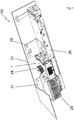
- Fig. 1 shows in a perspective view the door drive 100, how it can be installed in a building, which should also include installation on ships and aircraft, and a door drive 100 of this type is used, for example, as a drive in automatic sliding door systems.
- the basic structure of the door drive 100 forms a carrier profile 23, which is shown abbreviated for a simpler view, in addition, the essential upper part of the L-shaped carrier profile 23 is shown cut open in order to make the other important components of the door drive 100 visible.
- the door drive 100 has a motor unit 1 as a central component, and the motor unit 1 has the basic shape of a cuboid which forms the housing 10 of the motor unit.
- a pulley 24 is arranged on the motor unit 1, over which a toothed belt can be placed, with which the connection to the wing element or elements, for example the sliding glass elements , will be produced.
- the door drive 100 Adjacent to the motor unit 1, the door drive 100 has a power supply unit 25 and a controller 26, and the power supply unit 25 and the controller 26 are connected arranged opposite sides of the motor unit 1.
- the motor unit 1 is fastened to the carrier profile 23 with a first flange element 27, the first flange element 27 at the same time also accommodating the power supply unit 25.
- the motor unit 1 is connected to the carrier profile 23 with a second flange element 28, the second flange element 28 at the same time also accommodating the controller 26.
- the design of a single flange is also possible in order to accommodate at least the motor unit 1, the power supply 25 and the controller 26; there is also the possibility that the motor unit 1, the power supply 25 and / or the controller 26 can each be arranged with separate flange elements have in or on the carrier profile 23.
- Fig. 2 shows a perspective view of the isolated motor unit 1 with a housing 10, which is only shown with a lower housing half, while an upper housing half has been removed in order to show the motor unit 1 with the essential components.
- the stator 11 and the rotor 12 with the output shaft 13 are accommodated within the two housing halves of the housing 10. Outside the part of the housing 10 (not shown), a belt pulley 24 is mounted on the protruding part of the output shaft 13.
- a printed circuit board 21 is arranged on the underside, on the side of the housing 10 opposite the arrangement of the belt pulley 24.
- the housing 10 has the shape of a cuboid, and the circuit board 21 is designed in a rectangular shape and takes up the rectangular basic shape of the housing 10 of the motor unit 1 and is adapted to this.
- Fig. 3 shows the stator 11 with the laminated core 17 and with the winding carrier 18, and on the latter, the total of twelve coils 15 are applied to teeth 14 pointing radially inward, which consist of the There are laminated laminations, at least in the area of the teeth 14, the laminated laminated core with the winding carrier 18 made of plastic is enclosed by an injection molding.
- a first winding unit is formed on a first side of the six coils and on the opposite side another six coils form a second winding unit, the winding units not being electrically connected to one another and being able to be operated separately with respectively assigned motor output stages.
- the two winding units are indicated by a dot-dash line in their division plane.
- Each of the coils 15 is thus seated on an associated tooth 14 of the stator 11, and the coils 15 are directed radially inward.
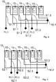
- the Figures 4 and 5 each show schematic views of a winding unit with a total of three strands S1.1, S1.2 and S1.3 for the first winding unit and strands S2.1, S2.2 and S2.3 for the second winding unit.
- Adjacent coils 15 form coil pairs so that the coil pairs are listed in pairs as follows: first coil pair: coil 1 and coil 2, second coil pair: coil 3 and coil 4, third coil pair: coil 5 and coil 6, fourth coil pair: coil 7 and Coil 8, fifth coil pair: coil 9 and coil 10 and sixth coil pair: coil 11 and coil 12.
- the coil pairs 1,2; 3, 4 and 5, 6 form the first winding unit, which is electrically separated from the second winding unit, which is formed by the coil pairs 7, 8; 9.10 and 11.12.
- the coil pairs have, from coil pair to coil pair, a winding pair direction which is identical to one another.
- the adjacent coils are each wound in opposite directions.
- each coil pair is assigned coils 15 which are wound in opposite directions to one another.
- the strands S1.1, S1.2, S1.3, S2.1, S2.2 and S2.3 each have connections of a first phase P1.1, P1.2, P1.3, P2.1, P2.2 , P2.3 on, and on an opposite side, the strands are assigned to the star points 16.1 and 16.2.
- the exemplary embodiment shows that for every second successive coil pair, the strand S1.1, S1.3, S2.2, starting from the connection of the phase P1.1, P1.3, P2.2, is fed to the side of a first coil 15 of the coil pair and the Connection to the star point 16.1, 16.2 is led out between the two coils 15 of the coil pair. It is also provided in an alternating manner that the strand S1.2, S2.1, S2.3 is supplied starting from the connection of the phase P1.2, P2.1, P2.3 between the two coils 15 of the coil pair and the connection to the star points 16. 1, 16.2 is led out laterally of a first coil 15 of the coil pairs.
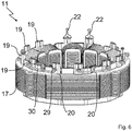
- the stator 11 has according to Fig. 6 a laminated lamella packet 17, around which a winding carrier 18 is formed at least in sections, in the exemplary embodiment on the inside and for this on the top and bottom sides.
- the winding wire of the strands is on and or on the winding carrier arranged.
- the winding support 18 has projections 19 on which the connections of the strands are arranged.
- the winding wire has intermediate sections 20 which are molded onto the winding support 18 and, in particular, are guided around the molding 19.
- the projections 19 protrude laterally from the stator 11, and electrical contact elements can be introduced onto them, of which two contact elements 22 are shown by way of example. If the winding wire is in contact with the contact elements 22, it can be sheared off on the outside in a final work step.
- projections 29 directed radially outward are provided on the projections 19, around which the winding wire is wound, and an auxiliary cut 30 extends from projection 29 to projection 29.
- an auxiliary section 30 between two projections 29 is also removed so that the phase and star point connections are provided with the projections 19 for subsequent contact with the circuit board 21, on which the phases and the star point connections are connected.
Landscapes
- Engineering & Computer Science (AREA)
- Power Engineering (AREA)
- Windings For Motors And Generators (AREA)
Abstract
Description
- Die Erfindung betrifft eine Motoreinheit für einen Türantrieb zur Anordnung an oder in Verbindung mit einer Türanlage, mit der zumindest ein Flügelelement der Türanlage bewegbar ist, aufweisend ein Gehäuse, in dem der Stator ruhend aufgenommen ist und wobei ein Rotor drehbeweglich im Gehäuse angeordnet ist, der eine Abtriebswelle aufweist, wobei die Abtriebswelle mit dem Flügelelement antreibend in Wirkverbindung bringbar ist. Der Stator weist ein Wicklungssystem mit einer ersten Wicklungseinheit auf, umfassend drei Stränge, und mit einer zweiten Wicklungseinheit, umfassend weitere drei Stränge, wobei die Wicklungseinheiten elektrisch voneinander getrennt sind, und wobei der Stator eine Anzahl von zueinander benachbarten Zähnen aufweist, auf denen die Stränge zu Spulen aufgewickelt sind.
- Die
EP 3 016 247 B1 beschreibt eine Motoreinheit für einen Türantrieb, und der Stator der Motoreinheit weist ein Wicklungssystem mit einer ersten Wicklungseinheit, aufweisend drei Stränge, und mit einer zweiten Wicklungseinheit, ebenfalls aufweisend drei Stränge, auf. Die Wicklungseinheiten sind elektrisch voneinander getrennt, wobei der Stator eine Anzahl von zueinander benachbarten Zähnen umfasst, auf denen die Stränge zu Spulen aufgewickelt sind. - Bei der automatischen Bewicklung von Statoren mit einem Wickelautomaten ist es von Vorteil, bestimmte Wicklungsrichtungen einzuhalten, sodass die Spulen der Statoren nicht ein zu komplexes Wickelschema erfordern.
- Die Wickelrichtung für allel Spulen, beispielsweise zwölf Spulen auf einem etwa ringförmigen Stator, muss genau eingehalten werden, sonst kann es zur Fehlfunktion der Motoreinheit kommen.
- Sind die Spulen so gewickelt, dass die Wicklungsdrähte aus den selben Zwischenräumen zwischen den Zähnen herausgeführt werden, so kann bauraumbedingt das Problem der Kontaktierung der Wicklungsdrähte entstehen, sodass es wünschenswert ist, die Wicklungsdrähte möglichst beabstandet zueinander gleichmäßig aus den Zwischenräumen der Spulen herauszuführen, beispielsweise ein Wicklungsdraht pro Zwischenraum. Das führt zudem zu einer möglichst gleichmäßigen Anordnung der elektrischen Kontakte am Umfang des Stators. Der Stator weist in der Regel einen Wicklungsträger aus einem Kunststoff-Spritzgussbauteil auf, der das Blechlamellenpaket durch den ausgeführten Spritzguss umschließt.
- Besonders vorteilhaft ist es beispielsweise, wenn sich die Wickelrichtung entweder gleichförmig oder in einem Rhythmus über den gesamten Umfang des Stators periodisch wiederholt. Wickelsysteme der hier interessierenden Art bilden sogenannte Sternpunkte, und es können Spulenpaare gebildet werden, bei denen eine Phase angeschlossen wird und ein weiteres Wicklungsende an einem Sternpunkt angebunden wird. Zwölf Spulen, die zwei getrennt voneinander vorhandene Wicklungseinheiten bilden, sind drei Phasen pro Wicklungseinheit vorgesehen, sodass bei zwei Sternpunkten mit jeweils drei Anschlüssen insgesamt sechs Phasenanschlüsse und sechs Sternpunktanschlüsse entstehen, also 12 Wicklungsdrahtkontaktierungen insgesamt.
- Die Aufgabe der Erfindung liegt in der Weiterbildung einer Motoreinheit mit einem verbesserten Wicklungssystem, insbesondere mit einem Wicklungssystem, das auf einfache Weise extern beschaltet werden kann, und der Wicklungsdraht der Spulen auf dem Stator sollte mit den einzelnen Anschlüssen möglichst nicht bauraumkritisch aus den Wicklungen herausgeführt werden. Zudem sollte ein Wickelschema bereitgestellt werden, das mit einem Wickelautomaten auf vorteilhafte Weise hergestellt werden kann.
- Diese Aufgabe wird ausgehend von einer Motoreinheit gemäß dem Oberbegriff des Anspruches 1 in Verbindung mit den kennzeichnenden Merkmalen gelöst. Vorteilhafte Weiterbildungen der Erfindung sind in den abhängigen Ansprüchen und in der Beschreibung angegeben.
- Die Erfindung schließt die technische Lehre ein, dass die Wickelrichtung der zueinander benachbarten Spulen wenigstens einer der Wicklungseinheiten von Spule zu Spule abwechselnd ausgebildet ist. Vorteilhafterweise ist die Wickelrichtung der zueinander benachbarten Spulen beider Wicklungseinheiten von Spule zu Spule abwechselnd ausgebildet, auch von benachbarten Spulen der jeweiligen Wicklungseinheit auf dem Umfang des Stators.
- Der Kerngedanke der Erfindung betrifft damit ein Wicklungssystem, bei dem jeder der aufeinander folgenden Spulen ungeachtet der Zugehörigkeit zu einer Wicklungseinheit auf dem vollen Umfang des Stators eine abwechselnde Wickelrichtung von Spule zu Spule aufweist. Durch ein solches Wicklungssystem ist ein Stator mit einem Wickelautomaten auf verbesserte, insbesondere einfache Weise bewickelbar, da der Wickelautomat periodisch wiederkehrende sich exakt und über dem gesamten Umfang abwechselnde Wickelrichtungen abfahren kann, und jeder Spule kann ein elektrischer Kontakt zugeordnet werden, wodurch sich auf dem Umfang eine gleichmäßige Verteilung der Kontakte der Wicklungsdrähte mit zueinander gleichem Abstand ergibt. Darüber hinaus sind keine Drahtüberschneidungen am Stator mehr vorhanden, da außen am Bund des Stators nur ein einziger Draht herumgeführt werden muss, um diesen zur nächsten Spule zu führen.
- Nach einer vorteilhaften Ausführungsform bilden jeweils zwei benachbarte Spulen ein Spulenpaar, die einen gemeinsamen Strang aufweisen. Die Spulenpaare können mit Bezug auf ihre beiden Spulen von Spulenpaar zu Spulenpaar immer eine identische Wickelpaarrichtung aufweisen. Insofern ergibt sich ein Gesamt-Wicklungssystem auf dem Stator, gemäß dem die Wickelrichtung links, rechts, links, rechts, links, rechts usw. orientiert ist.
- Die Stränge der Wicklungseinheiten weisen jeweils Anschlüsse einerseits an eine Phase und andererseits an einem Sternpunkt auf, wobei der ersten Wicklungseinheit ein erster Sternpunkt und der zweiten Wicklungseinheit ein zweiter Sternpunkt zugeordnet sind. Die Wicklungsdrähte der einzelnen Spulen werden im Sternpunkt miteinander verbunden, und mit drei Strängen pro Wicklungseinheit werden drei Wicklungsdrähte auf einen jeweiligen Sternpunkt geführt, und jede Wicklungseinheit weist drei Phasen auf.
- Weiterhin ist für jedes zweite aufeinanderfolgende Spulenpaar gemäß einer bevorzugten Ausführungsform vorgesehen, dass der Strang vom Anschluss der Phase beginnend seitlich einer ersten Spule des Spulenpaares dieser zugeführt ist und der Anschluss an den Sternpunkt zwischen den beiden Spulen des Spulenpaares aus diesem herausgeführt ist. Weiterhin ist vorteilhafterweise für jedes zweite aufeinanderfolgende Spulenpaar vorgesehen, dass der Strang vom Anschluss der Phase beginnend zwischen den beiden Spulen des Spulenpaares diesem zugeführt ist, und der Anschluss an den Sternpunkt seitlich einer ersten Spule des Spulenpaares aus diesem herausgeführt ist. Insofern sind die Anschlüsse an die Phase und die Sternpunkte jedes zweiten Spulenpaares in sich wiederholender Weise gleich ausgeführt.
- Der Stator weist vorzugsweise ein Blechlamellenpaket auf, um das herum wenigstens abschnittsweise ein Wicklungsträger ausgebildet ist, wobei der Wicklungsdraht der Stränge auf dem Wicklungsträger im Bereich der vorspringenden Zähne angeordnet ist. Der Wicklungsträger dient dabei nicht nur zur Aufnahme der Spulen, die gebildet sind mit den Wicklungen aus dem Wicklungsdraht, sondern der Wicklungsträger dient zudem auch zur haltenden Anordnung der Stränge der Wicklungseinheiten.
- Für diese Haltefunktion kann der Wicklungsträger Anformungen aufweisen, an denen die Anschlüsse der Stränge angeordnet sind. Die Anformungen bilden beispielsweise domartige Vorsprünge, die sich über den Stator, insbesondere über das Blechlamellenpaket, in Höhenrichtung des Stators fortsetzend erstrecken. Der Stator weist nach innen gerichtete Zähne auf, auf denen die Spulen mit dem Wicklungsdraht aufgebracht sind, und der Wicklungsdraht wird sowohl für den Beginn des Wicklungsdrahtes einer Spule als auch für das Ende des Wicklungsdrahtes einer Spule radial nach außen hin zu den Anformungen geführt, wobei dann, wenn der Wicklungsdraht von Spule zu Spule durchgehend verläuft, der Wicklungsdraht außenseitig an den Anformungen herumgeführt wird.
- Mit besonderem Vorteil bildet der Wicklungsdraht zwischen den beiden Spulen des Spulenpaares am Wicklungsträger Zwischenabschnitte, die am Wicklungsträger angeordnet und insbesondere um die Anformung außenseitig herumgeführt sind. Die Zwischenabschnitte bilden somit Abschnitte des Wicklungsdrahtes von Spule zu Spule.
- Nach einer noch weiteren Ausgestaltung der erfindungsgemäßen Motoreinheit ist eine Leiterkarte vorgesehen, wobei die Leiterkarte außenseitig am Gehäuse angeordnet ist und mit den Anschlüssen der Stränge elektrisch kontaktiert ist. Insbesondere erfolgt die elektrische Kontaktierung kabellos, beispielsweise mittels Steckkontakte oder mittels sonstiger Kontaktelemente. Insbesondere können an den Anformungen elektrische Kontaktelemente angeordnet sein, mittels denen die Anschlüsse der Stränge elektrisch kontaktiert sind und/oder an denen die Leiterkarte haltend angeordnet ist. Insbesondere ist die Leiterkarte mit den elektrischen Kontaktelementen an den Anformungen ebenfalls elektrisch kontaktiert, sodass die Kontaktelemente die Leiterkarte sowohl mit dem Wicklungsdraht der Spulen elektrisch kontaktieren als auch die Leiterkarte haltend an der Motoreinheit anordnen.
- Die Leiterkarte kann Leiterbahnen mit entsprechenden Kontaktelementen aufweisen, über die die Phasen und die Sternpunkte entsprechend beschaltet werden können. Beispielsweise können drei Wicklungsdrähte pro Wicklungseinheit jeweils einen Sternpunkt auf der Leiterkarte bilden, indem drei Wicklungsdrähte über drei zugeordnete elektrische Kontaktelemente mit einer gemeinsamen Leiterbahnen auf der Leiterkarte elektrisch verbunden sind. Die Phasen können separat mit Leiterbahnen auf der Leiterkarte verbunden werden, dies ebenfalls über separate elektrische Kontaktelemente. Die Phasen sind bei zwei Wicklungseinheiten insofern 6-fach vorhanden und können über entsprechende Einzel-Leiter fern der Leiterkarte der Steuerung zugeführt werden.
- Die Erfindung betrifft ferner einen Türantrieb mit einer Motoreinheit gemäß obenstehender Darstellung. Weiterhin betrifft die Erfindung eine Türanlage mit einem solchen Türantrieb.
- Die Türanlage kann ein Verbindungselement zum Verbinden mit einem Flügelelement aufweisen. Zusätzlich oder alternativ kann die Türanlage wenigstens ein Flügelelement, mit dem der Türantrieb antreibend in Wirkverbindung steht, aufweisen.
- Beispielsweise kann die Türanlage als eine Schiebetüranlage ausgebildet sein. Die Schiebetüranlage kann einen Riemen, insbesondere einen Zahnriemen, umfassen. Das Verbindungselement kann zumindest mittelbar mit dem Riemen verbunden sein. Das Verbindungselement kann als Läufer, insbesondere als Rollwagen, ausgebildet sein. Das Verbindungselement kann in einer Schiene, insbesondere in einer Schiene eines Trägerprofils, laufen. Der Riemen kann zwischen Riemenscheiben der Türanlage gespannt sein. Eine der Riemenscheiben kann als die Riemenscheibe des erfindungsgemäßen Türantriebs ausgebildet sein. Der Türantrieb kann in dem Trägerprofil angeordnet sein.
- Weitere, die Erfindung verbessernde Maßnahmen werden nachstehend gemeinsam mit der Beschreibung eines bevorzugten Ausführungsbeispiels der Erfindung anhand der Figuren näher dargestellt. Es zeigt:
- Fig. 1
- eine Gesamtansicht des Türantriebs mit einer Motoreinheit, die als Direktantrieb ausgeführt ist,
- Fig. 2
- eine Ansicht der Motoreinheit mit einem geöffneten Gehäuse,
- Fig. 3
- eine Draufsicht auf den Stator mit zwölf Spulen,
- Fig. 4
- eine schematische Ansicht einer ersten Wicklungseinheit des Wicklungssystems,
- Fig. 5
- eine schematische Ansicht einer zweiten Wicklungseinheit des Wicklungssystems und
- Fig. 6
- eine perspektivische Ansicht des Stators der Motoreinheit mit der Führung des Wicklungsdrahtes.
-
Fig. 1 zeigt in einer perspektivischen Ansicht den Türantrieb 100, wie dieser in einem Gebäude installiert werden kann, womit auch die Installation auf Schiffen und Flugzeugen umfasst sein soll, und ein Türantrieb 100 dieser Art dient beispielsweise als Antrieb in automatischen Schiebetüranlagen. - Die Grundstruktur des Türantriebs 100 bildet ein Trägerprofil 23, welches zu einfacheren Ansicht verkürzt dargestellt ist, zudem ist der wesentliche obere Teil des L-förmigen Trägerprofils 23 aufgeschnitten gezeigt, um die weiteren wichtigen Komponenten des Türantriebs 100 sichtbar zu machen.
- Als zentraler Bestandteil weist der Türantrieb 100 eine Motoreinheit 1 auf, und die Motoreinheit 1 besitzt die Grundform eines Quaders, der das Gehäuse 10 der Motoreinheit bildet. Um einen Abtrieb und damit eine Verbindung zu einem nicht näher dargestellten Flügelelement einer Türanlage zu ermöglichen, ist an der Motoreinheit 1 eine Riemenscheibe 24 angeordnet, über die ein Zahnriemen gelegt werden kann, mit dem schließlich die Verbindung zu dem oder den Flügelelementen, beispielsweise den Glasschiebeelementen, hergestellt wird.
- Benachbart zur Motoreinheit 1 weist der Türantrieb 100 ein Netzteil 25 und eine Steuerung 26 auf, und das Netzteil 25 und die Steuerung 26 sind an sich gegenüberliegenden Seiten der Motoreinheit 1 angeordnet. Die Motoreinheit 1 ist mit einem ersten Flanschelement 27 am Trägerprofil 23 befestigt, wobei das erste Flanschelement 27 zugleich das Netzteil 25 mit aufnimmt. Weiterhin ist die Motoreinheit 1 mit einem zweiten Flanschelement 28 mit dem Trägerprofil 23 verbunden, wobei das zweiten Flanschelement 28 zugleich die Steuerung 26 mit aufnimmt. Alternativ ist auch die Ausführung eines einzigen Flansches möglich, um wenigstens die Motoreinheit 1, das Netzteil 25 und die Steuerung 26 aufzunehmen, ferner besteht die Möglichkeit, dass die Motoreinheit 1, das Netzteil 25 und/oder die Steuerung 26 jeweils zugeordnete separate Flanschelemente zur Anordnung in oder am Trägerprofil 23 aufweisen.
-
Fig. 2 zeigt eine perspektivische Ansicht der vereinzelten Motoreinheit 1 mit einem Gehäuse 10, das lediglich mit einer unteren Gehäusehälfte dargestellt ist, während eine obere Gehäusehälfte entfernt wurde, um die Motoreinheit 1 mit den wesentlichen Bestandteilen zu zeigen. - Innerhalb der beiden Gehäusehälften des Gehäuses 10 sind der Stator 11 und der Rotor 12 mit der Abtriebswelle 13 aufgenommen. Außerhalb des nicht dargestellten Teils des Gehäuses 10 ist auf dem hervorstehenden Teil der Abtriebswelle 13 eine Riemenscheibe 24 aufgebracht. Unterseitig, auf der der Anordnung der Riemenscheibe 24 gegenüberliegenden Seite des Gehäuses 10, ist eine Leiterkarte 21 angeordnet. Das Gehäuse 10 weist die Form eines Quaders auf, und die Leiterkarte 21 ist in einer Rechteckform ausgestaltet und greift dabei die rechteckige Grundform des Gehäuses 10 der Motoreinheit 1 auf und ist an diese angepasst.
-
Fig. 3 zeigt den Stator 11 mit dem Blechlamellenpaket 17 und mit dem Wicklungsträger 18, und auf letzterem sind die insgesamt zwölf Spulen 15 auf radial nach innen weisenden Zähnen 14 aufgebracht, die aus dem Blechlamellenpaket bestehen, wobei wenigstens im Bereich der Zähne 14 das Blechlamellenpaket mit dem Wicklungsträger 18 aus Kunststoff durch einen Spritzguss umschlossen ist. Auf einer ersten Seite der sechs Spulen ist eine erste Wicklungseinheit gebildet und gegenüberliegend bilden weitere sechs Spulen eine zweite Wicklungseinheit, wobei die Wicklungseinheiten elektrisch nicht miteinander verbunden sind und separat mit jeweils zugeordneten Motorendstufen betrieben werden können. Die beiden Wicklungseinheiten sind durch eine strichpunktierte Linie in ihrer Teilungsebene angedeutet. - Jeder der Spulen 15 sitzt damit auf einem zugeordneten Zahn 14 des Stators 11, und die Spulen 15 sind radial nach innen gerichtet.
- Die
Figuren 4 und 5 zeigen jeweils schematische Ansichten einer Wicklungseinheit mit insgesamt drei Strängen S1.1, S1.2 und S1.3 für die erste Wicklungseinheit und die Stränge S2.1, S2.2 uns S2.3 für die zweite Wicklungseinheit. Jeweils zueinander benachbarte Spulen 15 bilden Spulenpaare, sodass die Spulenpaare wie folgt paarweise aufgeführt sind: erstes Spulenpaar: Spule 1 und Spule 2, zweites Spulenpaar: Spule 3 und Spule 4, drittes Spulenpaar: Spule 5 und Spule 6, viertes Spulenpaar: Spule 7 und Spule 8, fünftes Spulenpaar: Spule 9 und Spule 10 und sechstes Spulenpaar: Spule 11 und Spule 12. - Die Spulenpaare 1,2; 3,4 und 5,6 bilden die erste Wicklungseinheit, die elektrisch getrennt ist von der zweiten Wicklungseinheit, die gebildet ist durch die Spulenpaare 7,8; 9,10 und 11,12.
- Die Spulenpaare weisen mit Bezug auf die beiden Spulen 15 von Spulenpaar zu Spulenpaar eine zueinander identische Wickelpaarrichtung auf. Hingegen sind die benachbarten Spulen jeweils gegensinnig gewickelt.
- Die Wicklungsrichtung ist dabei mit Pfeilen in den Strängen angedeutet. Daraus wird deutlich, dass jedem Spulenpaar Spulen 15 zugeordnet sind, die zueinander gegensinnig gewickelt sind.
- Die Stränge S1.1, S1.2, S1.3, S2.1, S2.2 und S2.3 weisen jeweils Anschlüsse einer ersten Phase P1.1, P1.2, P1.3, P2.1, P2.2, P2.3 auf, und auf einer gegenüberliegenden Seite sind die Stränge den Sternpunkten 16.1 und 16.2 zugewiesen.
- Das Ausführungsbeispiel zeigt, dass für jedes zweite aufeinanderfolgende Spulenpaar der Strang S1.1, S1.3, S2.2 vom Anschluss der Phase P1.1, P1.3, P2.2 beginnend seitlich einer ersten Spule 15 des Spulenpaares zugeführt ist und der Anschluss an den Sternpunkt 16.1, 16.2 zwischen den beiden Spulen 15 des Spulenpaares herausgeführt ist. Ebenso in abwechselnder Weise ist vorgesehen, dass der Strang S1.2, S2.1, S2.3 vom Anschluss der Phase P1.2, P2.1, P2.3 beginnend zwischen den beiden Spulen 15 des Spulenpaares zugeführt ist und der Anschluss an den Sternpunkten 16. 1, 16.2 seitlich einer ersten Spule 15 der Spulenpaare herausgeführt ist.
- Dadurch wird deutlich, dass zwischen jeder Spule 15 entweder ein Phasenanschluss oder ein Sternpunktanschluss herausragt, sodass die Anschlüsse zur späteren Beschaltung der Spulen gleichmäßig beabstandet und gleichmäßig verteilt über dem Umfang des Stators ausgeführt werden können.
- Der Stator 11 weist gemäß
Fig. 6 ein Blechlamellenpaket 17 auf, um das herum wenigstens abschnittsweise, im Ausführungsbeispiel innenseitig und dazu ober- und unterseitig, ein Wicklungsträger 18 ausgebildet ist. Dabei ist der Wicklungsdraht der Stränge auf und oder am Wicklungsträger angeordnet. Der Wicklungsträger 18 weist Anformungen 19 auf, an denen die Anschlüsse der Stränge angeordnet sind. - Der Wicklungsdraht weist zwischen benachbarten Spulen 15 eines jeden Spulenpaares am Wicklungsträger 18 Zwischenabschnitte 20 auf, die am Wicklungsträger 18 angeformt und insbesondere um die Anformung 19 herumgeführt sind. Die Anformungen 19 ragen seitlich vom Stator 11 ab und an diese können elektrisch Kontaktelemente eingebracht sein, von denen zwei Kontaktelemente 22 beispielhaft gezeigt sind. Ist der Wicklungsdraht mit den Kontaktelementen 22 kontaktiert, so kann dieser in einem finalen Arbeitsschritt außenseitig abgeschert werden. Hierzu sind an den Anformungen 19 radial nach außen gerichtete Vorsprünge 29 vorgesehen, um die herum der Wicklungsdraht gewickelt wird, und von Vorsprung 29 zu Vorsprung 29 erstreckt sich ein Hilfsbschnitt 30.
- Werden die Vorsprünge 29 nach Fertigstellung der Wicklung und nach Einsetzen jeder der Kontaktelemente 22 in die Anformungen 19 abgeschert, so wird auch ein Hilfsabschnitt 30 zwischen zwei Vorsprüngen 29 entfernt, sodass mit den Anformungen 19 die Phasen und Sternpunktanschlüsse bereitgestellt werden zur späteren Kontaktierung mit der Leiterplatte 21, auf der die Phasen und die Sternpunktanschlüsse beschaltet werden.
- Die Erfindung beschränkt sich in ihrer Ausführung nicht auf das vorstehend angegebenen bevorzugte Ausführungsbeispiel. Vielmehr ist eine Anzahl von Varianten denkbar, welche von der dargestellten Lösung auch bei grundsätzlich anders gearteten Ausführungen Gebrauch macht. Sämtliche aus den Ansprüchen, der Beschreibung oder den Zeichnungen hervorgehenden Merkmale und/oder Vorteile, einschließlich konstruktiver Einzelheiten oder räumlicher Anordnungen, können sowohl für sich als auch in den verschiedensten Kombinationen erfindungswesentlich sein.
-
- 100
- Türantrieb
- 1
- Motoreinheit
- 10
- Gehäuse
- 11
- Stator
- 12
- Rotor
- 13
- Abtriebswelle
- 14
- Zahn
- 15
- Spule
- 16.1
- Sternpunkt
- 16.2
- Sternpunkt
- 17
- Blechlamellenpaket
- 18
- Wicklungsträger
- 19
- Anformung
- 20
- Zwischenabschnitt
- 21
- Leiterkarte
- 22
- Kontaktelement
- 23
- Trägerprofil
- 24
- Riemenscheibe
- 25
- Netzteil
- 26
- Steuerung
- 27
- Flanschelement
- 28
- Flanschelement
- 29
- Vorsprung
- 30
- Hilfsabschnitt
- S1.1
- Strang
- S1.2
- Strang
- S1.3
- Strang
- S2.1
- Strang
- S2.2
- Strang
- S2.3
- Strang
- P1.1
- Phase
- P1.2
- Phase
- P1.3
- Phase
- P2.1
- Phase
- P2.2
- Phase
- P2.3
- Phase
Claims (14)
- Motoreinheit (1) für einen Türantrieb (100) zur Anordnung an oder in Verbindung mit einer Gebäudetür, mit dem zumindest ein Flügelelement der Gebäudetür bewegbar ist, aufweisend ein Gehäuse (10), in dem ein Stator (11) ruhend aufgenommen ist und wobei ein Rotor (12) drehbeweglich im Gehäuse (10) angeordnet ist, der eine Abtriebswelle (13) aufweist, wobei die Abtriebswelle (13) mit dem Flügelelement antreibend in Wirkverbindung bringbar ist, und wobei der Stator (11) ein Wicklungssystem mit einer ersten Wicklungseinheit aufweisend drei Stränge (S1.1, S1.2, S1.3) und einer zweiten Wicklungseinheit aufweisend drei Stränge (S2.1, S2.2, S2.3) umfasst, wobei die Wicklungseinheiten elektrisch voneinander getrennt sind, und wobei der Stator (11) eine Anzahl von zueinander benachbarten Zähnen (14) aufweist, auf denen die Stränge (S1.1, S1.2, S1.3, S2.1, S2.2, S2.3) zu Spulen (15) aufgewickelt sind,
dadurch gekennzeichnet, dass die Wickelrichtung der zueinander benachbarten Spulen (15) wenigstens einer der Wicklungseinheiten von Spule (15) zu Spule (15) abwechselnd ausgebildet ist. - Motoreinheit (1) nach Anspruch 1, dadurch gekennzeichnet, dass jeweils zwei benachbarte Spulen (15) ein Spulenpaar bilden, die einen gemeinsamen Strang (S1.1, S1.2, S1.3, S2.1, S2.2, S2.3) aufweisen.
- Motoreinheit (1) nach Anspruch 1 oder 2, dadurch gekennzeichnet, dass die Spulenpaare mit Bezug auf ihre beiden Spulen (15) von Spulenpaar zu Spulenpaar immer eine identische Wickelpaarrichtung aufweisen.
- Motoreinheit (1) nach einem der Anschlüsse 1 bis 3 aufweisen,
dadurch gekennzeichnet, dass die Stränge (S1.1, S1.2, S1.3, S2.1, S2.2, S2.3) jeweils Anschlüsse einerseits an eine Phase (P1.1, P1.2, P1.3, P2.1, P2.2, P2.3) und andererseits an einen Sternpunkt (16.1, 16.2) aufweisen, wobei der ersten Wicklungseinheit ein erster Sternpunkt (16.1) und der zweiten Wicklungseinheit ein zweiter Sternpunkt (16.2) zugeordnet ist. - Motoreinheit (1) nach einem der vorgenannten Ansprüche, dadurch gekennzeichnet, dass für jedes zweite aufeinander folgende Spulenpaar vorgesehen ist, dass der Strang (S1.1, S1.3, S2.2) vom Anschluss der Phase (P1.1, P1.3, P2.2) beginnend seitlich einer ersten Spule (15) des Spulenpaares diesen zugeführt ist und der Anschluss an den Sternpunkt (16.1, 16.2) zwischen den beiden Spulen (15) des Spulenpaares aus diesen herausgeführt ist.
- Motoreinheit (1) nach einem der vorgenannten Ansprüche, dadurch gekennzeichnet, dass für jedes zweite aufeinander folgende Spulenpaar vorgesehen ist, dass der Strang (S1.2, S2.1, S2.3) vom Anschluss der Phase (P1.2, P2.1, P2.3) beginnend zwischen den beiden Spulen (15) des Spulenpaares diesen zugeführt ist und der Anschluss an den Sternpunkt (16.1, 16.2) seitlich einer ersten Spule (15) des Spulenpaares aus diesen herausgeführt ist.
- Motoreinheit (1) nach einem der vorgenannten Ansprüche, dadurch gekennzeichnet, dass der Stator (11) ein Blechlamellenpaket (17) aufweist, um das herum wenigstens abschnittsweise ein Wicklungsträger (18) ausgebildet ist, wobei der Wicklungsdraht der Stränge (S1.1, S1.2, S1.3, S2.1, S2.2, S2.3) auf und/oder am Wicklungsträger (18) angeordnet ist.
- Motoreinheit (1) nach Anspruch 7, dadurch gekennzeichnet, dass der Wicklungsträger (18) Anformungen (19) aufweist, an denen die Anschlüsse der Stränge (S1.1, S1.2, S1.3, S2.1, S2.2, S2.3) angeordnet sind.
- Motoreinheit (1) nach einem der vorgenannten Ansprüche, dadurch gekennzeichnet, dass der Wicklungsdraht zwischen den beiden Spulen (15) des Spulenpaares am Wicklungsträger (18) Zwischenabschnitte (20) bildet, die am Wicklungsträger (18) angeordnet und/oder um die Anformungen (19) herumgeführt sind.
- Motoreinheit (1) nach einem der vorgenannten Ansprüche, dadurch gekennzeichnet, dass eine Leiterkarte (21) vorgesehen ist, wobei die Leiterkarte (21) außenseitig am Gehäuse (10) angeordnet und mit den Anschlüssen der Stränge (S1.1, S1.2, S1.3, S2.1, S2.2, S2.3) elektrisch kontaktiert ist.
- Motoreinheit (1) nach Anspruch 10, dadurch gekennzeichnet, dass an den Anformungen (19) elektrische Kontaktelemente (22) angeordnet sind, mit denen die Anschlüsse der Stränge (S1.1, S1.2, S1.3, S2.1, S2.2, S2.3) elektrisch kontaktiert sind und/oder an denen die Leiterkarte (21) haltend angeordnet ist.
- Motoreinheit (1) nach Anspruch 10 oder 11, dadurch gekennzeichnet, dass die Phasen (P1.1, P1.2, P1.3, P2.1, P2.2, P2.3) und/oder die Sternpunkte (16.1, 16.2) auf der Leiterkarte (21) beschaltet und extern elektrisch angebunden sind.
- Türantrieb (100) mit einer Motoreinheit (1) nach einem der vorgenannten Ansprüche.
- Türanlage mit einem Türantrieb (100) nach Anspruch 13, aufweisend wenigstens ein Verbindungselement zum Verbinden mit einem Flügelelement und/oder wenigstens ein Flügelelement, mit dem der Türantrieb (100) antreibend in Wirkverbindung steht.
Priority Applications (2)
| Application Number | Priority Date | Filing Date | Title |
|---|---|---|---|
| EP19214432.7A EP3836361A1 (de) | 2019-12-09 | 2019-12-09 | Motoreinheit für einen türantrieb zur anordnung an oder in verbindung mit einer gebäudetür |
| PCT/EP2020/083341 WO2021115782A1 (de) | 2019-12-09 | 2020-11-25 | Motoreinheit für einen türantrieb zur anordnung an oder in verbindung mit einer gebäudetür |
Applications Claiming Priority (1)
| Application Number | Priority Date | Filing Date | Title |
|---|---|---|---|
| EP19214432.7A EP3836361A1 (de) | 2019-12-09 | 2019-12-09 | Motoreinheit für einen türantrieb zur anordnung an oder in verbindung mit einer gebäudetür |
Publications (1)
| Publication Number | Publication Date |
|---|---|
| EP3836361A1 true EP3836361A1 (de) | 2021-06-16 |
Family
ID=68840907
Family Applications (1)
| Application Number | Title | Priority Date | Filing Date |
|---|---|---|---|
| EP19214432.7A Pending EP3836361A1 (de) | 2019-12-09 | 2019-12-09 | Motoreinheit für einen türantrieb zur anordnung an oder in verbindung mit einer gebäudetür |
Country Status (2)
| Country | Link |
|---|---|
| EP (1) | EP3836361A1 (de) |
| WO (1) | WO2021115782A1 (de) |
Citations (6)
| Publication number | Priority date | Publication date | Assignee | Title |
|---|---|---|---|---|
| JP3044554B2 (ja) * | 1989-07-18 | 2000-05-22 | 光洋精工株式会社 | 磁極装置 |
| CN201549943U (zh) * | 2009-11-11 | 2010-08-11 | 泰豪科技股份有限公司 | 一种二相中频整流发电机 |
| DE102009022899A1 (de) * | 2009-05-27 | 2010-12-02 | Brose Fahrzeugteile GmbH & Co. Kommanditgesellschaft, Würzburg | Stator für eine elektrische Maschine, insbesondere für einen bürstenlosen Gleichstrommotor |
| US20130043749A1 (en) * | 2010-09-22 | 2013-02-21 | Mitsubishi Electric Corporation | Rotary electric machine and method of manufacturing the same |
| US20140145547A1 (en) * | 2011-10-14 | 2014-05-29 | Mitsubishi Electric Corporation | Permanent magnet motor |
| EP3016247B1 (de) | 2014-10-31 | 2018-03-21 | dormakaba Deutschland GmbH | Türantrieb |
-
2019
- 2019-12-09 EP EP19214432.7A patent/EP3836361A1/de active Pending
-
2020
- 2020-11-25 WO PCT/EP2020/083341 patent/WO2021115782A1/de not_active Ceased
Patent Citations (6)
| Publication number | Priority date | Publication date | Assignee | Title |
|---|---|---|---|---|
| JP3044554B2 (ja) * | 1989-07-18 | 2000-05-22 | 光洋精工株式会社 | 磁極装置 |
| DE102009022899A1 (de) * | 2009-05-27 | 2010-12-02 | Brose Fahrzeugteile GmbH & Co. Kommanditgesellschaft, Würzburg | Stator für eine elektrische Maschine, insbesondere für einen bürstenlosen Gleichstrommotor |
| CN201549943U (zh) * | 2009-11-11 | 2010-08-11 | 泰豪科技股份有限公司 | 一种二相中频整流发电机 |
| US20130043749A1 (en) * | 2010-09-22 | 2013-02-21 | Mitsubishi Electric Corporation | Rotary electric machine and method of manufacturing the same |
| US20140145547A1 (en) * | 2011-10-14 | 2014-05-29 | Mitsubishi Electric Corporation | Permanent magnet motor |
| EP3016247B1 (de) | 2014-10-31 | 2018-03-21 | dormakaba Deutschland GmbH | Türantrieb |
Also Published As
| Publication number | Publication date |
|---|---|
| WO2021115782A1 (de) | 2021-06-17 |
Similar Documents
| Publication | Publication Date | Title |
|---|---|---|
| DE102015200089B4 (de) | Stator für eine elektrische Maschine und Verfahren zum Herstellen eines solchen | |
| EP1579550B1 (de) | Verschaltungselement für eine wicklung einer elektrischen maschine | |
| DE102015200095B4 (de) | Stator für eine elektrische Maschine und Verfahren zum Herstellen eines solchen | |
| DE102017206187B4 (de) | Motor mit Verdrahtungsplatte, die durch Verbinden einer Wicklung durch Crimpen ausgebildet wird | |
| DE102009031466B4 (de) | Elektromotor und Anlage mit Elektromotoren | |
| DE202015008207U1 (de) | Stator eines Elektromotors sowie Schalteinheit hierfür | |
| DE102016224425A1 (de) | Stator für einen Mehrphasen-Elektromotor, Verfahren zur Herstellung einer Spulenwicklung, und Elektromotor für ein handgehaltenes Werkzeug | |
| DE10328720A1 (de) | Verschaltungselement für eine Wicklung einer elektrischen Maschine | |
| EP2606559B1 (de) | Kontakteinrichtung in einem stator einer elektrischen maschine | |
| EP3824528A1 (de) | Elektromotor mit einer verschaltungseinheit und verfahren zur herstellung eines elektromotors mit einer verschaltungseinheit | |
| EP1943710A1 (de) | Elektromotor und wickelverfahren | |
| DE2251020C3 (de) | Anschlußvorrichtung | |
| DE102011078026A1 (de) | Schaltungsträger für die Verkabelung der Zahnspulenwicklungen eines Stators einer elektrischen Maschine und Bausatz, enthaltend einen solchen Schaltungsträger | |
| WO2006069841A1 (de) | Elektrische maschine, insbesondere ec-motor und verfahren zu seiner herstellung | |
| DE102020110651B4 (de) | Elektrische Kontaktierung eines Stators einer elektrischen Maschine | |
| DE69602489T2 (de) | Mehrpoliger Gleichstrommotor | |
| EP3824530B1 (de) | Elektromotor mit einer verschaltungseinheit | |
| WO2021115782A1 (de) | Motoreinheit für einen türantrieb zur anordnung an oder in verbindung mit einer gebäudetür | |
| DE10231092A1 (de) | Außenläufermotor | |
| WO2020015856A1 (de) | Elektromotor mit einer verschaltungseinheit und verfahren zur herstellung eines elektromotors mit einer verschaltungseinheit | |
| EP0107025A1 (de) | Am Ständerblechpaket einer elektrischen Kleinmaschine festlegbare Verbindungs-Vorrichtung und Verfahren zur Herstellung der Verbindungen | |
| DE102021214766A1 (de) | Stator für eine elektrische Maschine, eine elektrische Maschine und Verfahren zum Herstellen eines solchen Stators | |
| EP3835530B1 (de) | Türantrieb mit einer motoreinheit, aufweisend eine vorteilhafte elektrische beschaltung | |
| DE20121081U1 (de) | Klemmkasten einer elektrischen Maschine | |
| EP1603216B1 (de) | Bürstenloser Elektromotor und Verfahren zur Herstellung desselben |
Legal Events
| Date | Code | Title | Description |
|---|---|---|---|
| PUAI | Public reference made under article 153(3) epc to a published international application that has entered the european phase |
Free format text: ORIGINAL CODE: 0009012 |
|
| STAA | Information on the status of an ep patent application or granted ep patent |
Free format text: STATUS: THE APPLICATION HAS BEEN PUBLISHED |
|
| AK | Designated contracting states |
Kind code of ref document: A1 Designated state(s): AL AT BE BG CH CY CZ DE DK EE ES FI FR GB GR HR HU IE IS IT LI LT LU LV MC MK MT NL NO PL PT RO RS SE SI SK SM TR |
|
| STAA | Information on the status of an ep patent application or granted ep patent |
Free format text: STATUS: REQUEST FOR EXAMINATION WAS MADE |
|
| 17P | Request for examination filed |
Effective date: 20211215 |
|
| RBV | Designated contracting states (corrected) |
Designated state(s): AL AT BE BG CH CY CZ DE DK EE ES FI FR GB GR HR HU IE IS IT LI LT LU LV MC MK MT NL NO PL PT RO RS SE SI SK SM TR |
|
| STAA | Information on the status of an ep patent application or granted ep patent |
Free format text: STATUS: EXAMINATION IS IN PROGRESS |
|
| 17Q | First examination report despatched |
Effective date: 20240423 |