EP3836285A1 - Battery module having connector mounted on fpcb, and battery pack and vehicle comprising same - Google Patents
Battery module having connector mounted on fpcb, and battery pack and vehicle comprising same Download PDFInfo
- Publication number
- EP3836285A1 EP3836285A1 EP19904880.2A EP19904880A EP3836285A1 EP 3836285 A1 EP3836285 A1 EP 3836285A1 EP 19904880 A EP19904880 A EP 19904880A EP 3836285 A1 EP3836285 A1 EP 3836285A1
- Authority
- EP
- European Patent Office
- Prior art keywords
- fpcb
- connector
- battery module
- module according
- battery
- Prior art date
- Legal status (The legal status is an assumption and is not a legal conclusion. Google has not performed a legal analysis and makes no representation as to the accuracy of the status listed.)
- Pending
Links
Images


Classifications
-
- H—ELECTRICITY
- H01—ELECTRIC ELEMENTS
- H01M—PROCESSES OR MEANS, e.g. BATTERIES, FOR THE DIRECT CONVERSION OF CHEMICAL ENERGY INTO ELECTRICAL ENERGY
- H01M50/00—Constructional details or processes of manufacture of the non-active parts of electrochemical cells other than fuel cells, e.g. hybrid cells
- H01M50/50—Current conducting connections for cells or batteries
- H01M50/502—Interconnectors for connecting terminals of adjacent batteries; Interconnectors for connecting cells outside a battery casing
- H01M50/507—Interconnectors for connecting terminals of adjacent batteries; Interconnectors for connecting cells outside a battery casing comprising an arrangement of two or more busbars within a container structure, e.g. busbar modules
-
- H—ELECTRICITY
- H01—ELECTRIC ELEMENTS
- H01M—PROCESSES OR MEANS, e.g. BATTERIES, FOR THE DIRECT CONVERSION OF CHEMICAL ENERGY INTO ELECTRICAL ENERGY
- H01M10/00—Secondary cells; Manufacture thereof
- H01M10/04—Construction or manufacture in general
- H01M10/0413—Large-sized flat cells or batteries for motive or stationary systems with plate-like electrodes
-
- H—ELECTRICITY
- H01—ELECTRIC ELEMENTS
- H01M—PROCESSES OR MEANS, e.g. BATTERIES, FOR THE DIRECT CONVERSION OF CHEMICAL ENERGY INTO ELECTRICAL ENERGY
- H01M10/00—Secondary cells; Manufacture thereof
- H01M10/42—Methods or arrangements for servicing or maintenance of secondary cells or secondary half-cells
- H01M10/425—Structural combination with electronic components, e.g. electronic circuits integrated to the outside of the casing
-
- H—ELECTRICITY
- H01—ELECTRIC ELEMENTS
- H01M—PROCESSES OR MEANS, e.g. BATTERIES, FOR THE DIRECT CONVERSION OF CHEMICAL ENERGY INTO ELECTRICAL ENERGY
- H01M10/00—Secondary cells; Manufacture thereof
- H01M10/42—Methods or arrangements for servicing or maintenance of secondary cells or secondary half-cells
- H01M10/48—Accumulators combined with arrangements for measuring, testing or indicating the condition of cells, e.g. the level or density of the electrolyte
- H01M10/486—Accumulators combined with arrangements for measuring, testing or indicating the condition of cells, e.g. the level or density of the electrolyte for measuring temperature
-
- H—ELECTRICITY
- H01—ELECTRIC ELEMENTS
- H01M—PROCESSES OR MEANS, e.g. BATTERIES, FOR THE DIRECT CONVERSION OF CHEMICAL ENERGY INTO ELECTRICAL ENERGY
- H01M50/00—Constructional details or processes of manufacture of the non-active parts of electrochemical cells other than fuel cells, e.g. hybrid cells
- H01M50/10—Primary casings, jackets or wrappings of a single cell or a single battery
- H01M50/172—Arrangements of electric connectors penetrating the casing
- H01M50/174—Arrangements of electric connectors penetrating the casing adapted for the shape of the cells
- H01M50/178—Arrangements of electric connectors penetrating the casing adapted for the shape of the cells for pouch or flexible bag cells
-
- H—ELECTRICITY
- H01—ELECTRIC ELEMENTS
- H01M—PROCESSES OR MEANS, e.g. BATTERIES, FOR THE DIRECT CONVERSION OF CHEMICAL ENERGY INTO ELECTRICAL ENERGY
- H01M50/00—Constructional details or processes of manufacture of the non-active parts of electrochemical cells other than fuel cells, e.g. hybrid cells
- H01M50/20—Mountings; Secondary casings or frames; Racks, modules or packs; Suspension devices; Shock absorbers; Transport or carrying devices; Holders
- H01M50/204—Racks, modules or packs for multiple batteries or multiple cells
- H01M50/207—Racks, modules or packs for multiple batteries or multiple cells characterised by their shape
- H01M50/211—Racks, modules or packs for multiple batteries or multiple cells characterised by their shape adapted for pouch cells
-
- H—ELECTRICITY
- H01—ELECTRIC ELEMENTS
- H01M—PROCESSES OR MEANS, e.g. BATTERIES, FOR THE DIRECT CONVERSION OF CHEMICAL ENERGY INTO ELECTRICAL ENERGY
- H01M50/00—Constructional details or processes of manufacture of the non-active parts of electrochemical cells other than fuel cells, e.g. hybrid cells
- H01M50/20—Mountings; Secondary casings or frames; Racks, modules or packs; Suspension devices; Shock absorbers; Transport or carrying devices; Holders
- H01M50/284—Mountings; Secondary casings or frames; Racks, modules or packs; Suspension devices; Shock absorbers; Transport or carrying devices; Holders with incorporated circuit boards, e.g. printed circuit boards [PCB]
-
- H—ELECTRICITY
- H01—ELECTRIC ELEMENTS
- H01M—PROCESSES OR MEANS, e.g. BATTERIES, FOR THE DIRECT CONVERSION OF CHEMICAL ENERGY INTO ELECTRICAL ENERGY
- H01M50/00—Constructional details or processes of manufacture of the non-active parts of electrochemical cells other than fuel cells, e.g. hybrid cells
- H01M50/20—Mountings; Secondary casings or frames; Racks, modules or packs; Suspension devices; Shock absorbers; Transport or carrying devices; Holders
- H01M50/296—Mountings; Secondary casings or frames; Racks, modules or packs; Suspension devices; Shock absorbers; Transport or carrying devices; Holders characterised by terminals of battery packs
-
- H—ELECTRICITY
- H01—ELECTRIC ELEMENTS
- H01M—PROCESSES OR MEANS, e.g. BATTERIES, FOR THE DIRECT CONVERSION OF CHEMICAL ENERGY INTO ELECTRICAL ENERGY
- H01M50/00—Constructional details or processes of manufacture of the non-active parts of electrochemical cells other than fuel cells, e.g. hybrid cells
- H01M50/50—Current conducting connections for cells or batteries
- H01M50/502—Interconnectors for connecting terminals of adjacent batteries; Interconnectors for connecting cells outside a battery casing
- H01M50/519—Interconnectors for connecting terminals of adjacent batteries; Interconnectors for connecting cells outside a battery casing comprising printed circuit boards [PCB]
-
- H—ELECTRICITY
- H01—ELECTRIC ELEMENTS
- H01M—PROCESSES OR MEANS, e.g. BATTERIES, FOR THE DIRECT CONVERSION OF CHEMICAL ENERGY INTO ELECTRICAL ENERGY
- H01M50/00—Constructional details or processes of manufacture of the non-active parts of electrochemical cells other than fuel cells, e.g. hybrid cells
- H01M50/50—Current conducting connections for cells or batteries
- H01M50/531—Electrode connections inside a battery casing
-
- H—ELECTRICITY
- H01—ELECTRIC ELEMENTS
- H01M—PROCESSES OR MEANS, e.g. BATTERIES, FOR THE DIRECT CONVERSION OF CHEMICAL ENERGY INTO ELECTRICAL ENERGY
- H01M50/00—Constructional details or processes of manufacture of the non-active parts of electrochemical cells other than fuel cells, e.g. hybrid cells
- H01M50/50—Current conducting connections for cells or batteries
- H01M50/543—Terminals
- H01M50/547—Terminals characterised by the disposition of the terminals on the cells
- H01M50/548—Terminals characterised by the disposition of the terminals on the cells on opposite sides of the cell
-
- H—ELECTRICITY
- H01—ELECTRIC ELEMENTS
- H01R—ELECTRICALLY-CONDUCTIVE CONNECTIONS; STRUCTURAL ASSOCIATIONS OF A PLURALITY OF MUTUALLY-INSULATED ELECTRICAL CONNECTING ELEMENTS; COUPLING DEVICES; CURRENT COLLECTORS
- H01R12/00—Structural associations of a plurality of mutually-insulated electrical connecting elements, specially adapted for printed circuits, e.g. printed circuit boards [PCB], flat or ribbon cables, or like generally planar structures, e.g. terminal strips, terminal blocks; Coupling devices specially adapted for printed circuits, flat or ribbon cables, or like generally planar structures; Terminals specially adapted for contact with, or insertion into, printed circuits, flat or ribbon cables, or like generally planar structures
- H01R12/70—Coupling devices
- H01R12/77—Coupling devices for flexible printed circuits, flat or ribbon cables or like structures
-
- H—ELECTRICITY
- H05—ELECTRIC TECHNIQUES NOT OTHERWISE PROVIDED FOR
- H05K—PRINTED CIRCUITS; CASINGS OR CONSTRUCTIONAL DETAILS OF ELECTRIC APPARATUS; MANUFACTURE OF ASSEMBLAGES OF ELECTRICAL COMPONENTS
- H05K1/00—Printed circuits
- H05K1/02—Details
- H05K1/0277—Bendability or stretchability details
- H05K1/028—Bending or folding regions of flexible printed circuits
-
- H—ELECTRICITY
- H01—ELECTRIC ELEMENTS
- H01M—PROCESSES OR MEANS, e.g. BATTERIES, FOR THE DIRECT CONVERSION OF CHEMICAL ENERGY INTO ELECTRICAL ENERGY
- H01M10/00—Secondary cells; Manufacture thereof
- H01M10/42—Methods or arrangements for servicing or maintenance of secondary cells or secondary half-cells
- H01M10/425—Structural combination with electronic components, e.g. electronic circuits integrated to the outside of the casing
- H01M2010/4271—Battery management systems including electronic circuits, e.g. control of current or voltage to keep battery in healthy state, cell balancing
-
- H—ELECTRICITY
- H01—ELECTRIC ELEMENTS
- H01M—PROCESSES OR MEANS, e.g. BATTERIES, FOR THE DIRECT CONVERSION OF CHEMICAL ENERGY INTO ELECTRICAL ENERGY
- H01M2220/00—Batteries for particular applications
- H01M2220/20—Batteries in motive systems, e.g. vehicle, ship, plane
-
- H—ELECTRICITY
- H01—ELECTRIC ELEMENTS
- H01M—PROCESSES OR MEANS, e.g. BATTERIES, FOR THE DIRECT CONVERSION OF CHEMICAL ENERGY INTO ELECTRICAL ENERGY
- H01M50/00—Constructional details or processes of manufacture of the non-active parts of electrochemical cells other than fuel cells, e.g. hybrid cells
- H01M50/20—Mountings; Secondary casings or frames; Racks, modules or packs; Suspension devices; Shock absorbers; Transport or carrying devices; Holders
- H01M50/271—Lids or covers for the racks or secondary casings
-
- H—ELECTRICITY
- H01—ELECTRIC ELEMENTS
- H01M—PROCESSES OR MEANS, e.g. BATTERIES, FOR THE DIRECT CONVERSION OF CHEMICAL ENERGY INTO ELECTRICAL ENERGY
- H01M50/00—Constructional details or processes of manufacture of the non-active parts of electrochemical cells other than fuel cells, e.g. hybrid cells
- H01M50/20—Mountings; Secondary casings or frames; Racks, modules or packs; Suspension devices; Shock absorbers; Transport or carrying devices; Holders
- H01M50/289—Mountings; Secondary casings or frames; Racks, modules or packs; Suspension devices; Shock absorbers; Transport or carrying devices; Holders characterised by spacing elements or positioning means within frames, racks or packs
-
- H—ELECTRICITY
- H01—ELECTRIC ELEMENTS
- H01M—PROCESSES OR MEANS, e.g. BATTERIES, FOR THE DIRECT CONVERSION OF CHEMICAL ENERGY INTO ELECTRICAL ENERGY
- H01M50/00—Constructional details or processes of manufacture of the non-active parts of electrochemical cells other than fuel cells, e.g. hybrid cells
- H01M50/50—Current conducting connections for cells or batteries
- H01M50/569—Constructional details of current conducting connections for detecting conditions inside cells or batteries, e.g. details of voltage sensing terminals
-
- H—ELECTRICITY
- H01—ELECTRIC ELEMENTS
- H01R—ELECTRICALLY-CONDUCTIVE CONNECTIONS; STRUCTURAL ASSOCIATIONS OF A PLURALITY OF MUTUALLY-INSULATED ELECTRICAL CONNECTING ELEMENTS; COUPLING DEVICES; CURRENT COLLECTORS
- H01R12/00—Structural associations of a plurality of mutually-insulated electrical connecting elements, specially adapted for printed circuits, e.g. printed circuit boards [PCB], flat or ribbon cables, or like generally planar structures, e.g. terminal strips, terminal blocks; Coupling devices specially adapted for printed circuits, flat or ribbon cables, or like generally planar structures; Terminals specially adapted for contact with, or insertion into, printed circuits, flat or ribbon cables, or like generally planar structures
- H01R12/50—Fixed connections
- H01R12/59—Fixed connections for flexible printed circuits, flat or ribbon cables or like structures
- H01R12/65—Fixed connections for flexible printed circuits, flat or ribbon cables or like structures characterised by the terminal
-
- H—ELECTRICITY
- H01—ELECTRIC ELEMENTS
- H01R—ELECTRICALLY-CONDUCTIVE CONNECTIONS; STRUCTURAL ASSOCIATIONS OF A PLURALITY OF MUTUALLY-INSULATED ELECTRICAL CONNECTING ELEMENTS; COUPLING DEVICES; CURRENT COLLECTORS
- H01R12/00—Structural associations of a plurality of mutually-insulated electrical connecting elements, specially adapted for printed circuits, e.g. printed circuit boards [PCB], flat or ribbon cables, or like generally planar structures, e.g. terminal strips, terminal blocks; Coupling devices specially adapted for printed circuits, flat or ribbon cables, or like generally planar structures; Terminals specially adapted for contact with, or insertion into, printed circuits, flat or ribbon cables, or like generally planar structures
- H01R12/70—Coupling devices
- H01R12/77—Coupling devices for flexible printed circuits, flat or ribbon cables or like structures
- H01R12/777—Coupling parts carrying pins, blades or analogous contacts
-
- H—ELECTRICITY
- H05—ELECTRIC TECHNIQUES NOT OTHERWISE PROVIDED FOR
- H05K—PRINTED CIRCUITS; CASINGS OR CONSTRUCTIONAL DETAILS OF ELECTRIC APPARATUS; MANUFACTURE OF ASSEMBLAGES OF ELECTRICAL COMPONENTS
- H05K1/00—Printed circuits
- H05K1/18—Printed circuits structurally associated with non-printed electric components
- H05K1/189—Printed circuits structurally associated with non-printed electric components characterised by the use of a flexible or folded printed circuit
-
- H—ELECTRICITY
- H05—ELECTRIC TECHNIQUES NOT OTHERWISE PROVIDED FOR
- H05K—PRINTED CIRCUITS; CASINGS OR CONSTRUCTIONAL DETAILS OF ELECTRIC APPARATUS; MANUFACTURE OF ASSEMBLAGES OF ELECTRICAL COMPONENTS
- H05K2201/00—Indexing scheme relating to printed circuits covered by H05K1/00
- H05K2201/05—Flexible printed circuits [FPCs]
- H05K2201/056—Folded around rigid support or component
-
- H—ELECTRICITY
- H05—ELECTRIC TECHNIQUES NOT OTHERWISE PROVIDED FOR
- H05K—PRINTED CIRCUITS; CASINGS OR CONSTRUCTIONAL DETAILS OF ELECTRIC APPARATUS; MANUFACTURE OF ASSEMBLAGES OF ELECTRICAL COMPONENTS
- H05K2201/00—Indexing scheme relating to printed circuits covered by H05K1/00
- H05K2201/10—Details of components or other objects attached to or integrated in a printed circuit board
- H05K2201/10007—Types of components
- H05K2201/10037—Printed or non-printed battery
-
- H—ELECTRICITY
- H05—ELECTRIC TECHNIQUES NOT OTHERWISE PROVIDED FOR
- H05K—PRINTED CIRCUITS; CASINGS OR CONSTRUCTIONAL DETAILS OF ELECTRIC APPARATUS; MANUFACTURE OF ASSEMBLAGES OF ELECTRICAL COMPONENTS
- H05K2201/00—Indexing scheme relating to printed circuits covered by H05K1/00
- H05K2201/10—Details of components or other objects attached to or integrated in a printed circuit board
- H05K2201/10007—Types of components
- H05K2201/10151—Sensor
-
- H—ELECTRICITY
- H05—ELECTRIC TECHNIQUES NOT OTHERWISE PROVIDED FOR
- H05K—PRINTED CIRCUITS; CASINGS OR CONSTRUCTIONAL DETAILS OF ELECTRIC APPARATUS; MANUFACTURE OF ASSEMBLAGES OF ELECTRICAL COMPONENTS
- H05K2201/00—Indexing scheme relating to printed circuits covered by H05K1/00
- H05K2201/10—Details of components or other objects attached to or integrated in a printed circuit board
- H05K2201/10007—Types of components
- H05K2201/10189—Non-printed connector
-
- H—ELECTRICITY
- H05—ELECTRIC TECHNIQUES NOT OTHERWISE PROVIDED FOR
- H05K—PRINTED CIRCUITS; CASINGS OR CONSTRUCTIONAL DETAILS OF ELECTRIC APPARATUS; MANUFACTURE OF ASSEMBLAGES OF ELECTRICAL COMPONENTS
- H05K2201/00—Indexing scheme relating to printed circuits covered by H05K1/00
- H05K2201/20—Details of printed circuits not provided for in H05K2201/01 - H05K2201/10
- H05K2201/2009—Reinforced areas, e.g. for a specific part of a flexible printed circuit
-
- Y—GENERAL TAGGING OF NEW TECHNOLOGICAL DEVELOPMENTS; GENERAL TAGGING OF CROSS-SECTIONAL TECHNOLOGIES SPANNING OVER SEVERAL SECTIONS OF THE IPC; TECHNICAL SUBJECTS COVERED BY FORMER USPC CROSS-REFERENCE ART COLLECTIONS [XRACs] AND DIGESTS
- Y02—TECHNOLOGIES OR APPLICATIONS FOR MITIGATION OR ADAPTATION AGAINST CLIMATE CHANGE
- Y02E—REDUCTION OF GREENHOUSE GAS [GHG] EMISSIONS, RELATED TO ENERGY GENERATION, TRANSMISSION OR DISTRIBUTION
- Y02E60/00—Enabling technologies; Technologies with a potential or indirect contribution to GHG emissions mitigation
- Y02E60/10—Energy storage using batteries
-
- Y—GENERAL TAGGING OF NEW TECHNOLOGICAL DEVELOPMENTS; GENERAL TAGGING OF CROSS-SECTIONAL TECHNOLOGIES SPANNING OVER SEVERAL SECTIONS OF THE IPC; TECHNICAL SUBJECTS COVERED BY FORMER USPC CROSS-REFERENCE ART COLLECTIONS [XRACs] AND DIGESTS
- Y02—TECHNOLOGIES OR APPLICATIONS FOR MITIGATION OR ADAPTATION AGAINST CLIMATE CHANGE
- Y02P—CLIMATE CHANGE MITIGATION TECHNOLOGIES IN THE PRODUCTION OR PROCESSING OF GOODS
- Y02P70/00—Climate change mitigation technologies in the production process for final industrial or consumer products
- Y02P70/50—Manufacturing or production processes characterised by the final manufactured product
Definitions
- the present disclosure relates to a battery module including a connector mounted on a FPCB, and a battery pack and a vehicle including the battery module, and more particularly, to a battery module including a connector mounted to both ends of a FPCB installed across a cell stack and provided using a space formed by biased arrangement of an electrode lead, and a battery pack and a vehicle including the battery module.
- a control device such as a battery management system (BMS) for controlling charging and discharging of a battery module by using information such as voltage of each battery cell and temperature of a cell stack of the battery module may be connected to the battery module.
- BMS battery management system
- the present disclosure is designed to solve the problems of the related art, and therefore the present disclosure is directed to enhancing the structure for electrical connection between a FPCB and a connector to improve productivity and reduce defect rate, and also minimizing the increase in volume of a battery module caused by installing the connector.
- a battery module comprising: a cell stack formed by stacking a plurality of battery cells; a bus bar frame assembly including a bus bar frame configured to cover one longitudinal end and the other longitudinal end of the cell stack and a plurality of bus bars fixed on the bus bar frame and electrically connected to the battery cells; and a FPCB assembly including a first FPCB extending along a longitudinal direction of the cell stack to cover at least a portion of an upper surface of the cell stack, a second FPCB extending from one longitudinal end of the first FPCB and electrically connected to the bus bars, and a connector having a connector pin inserted into a pin insert hole formed in the second FPCB.
- the battery cell may include an electrode assembly; a pair of electrode leads connected to the electrode assembly and extending in opposite directions along a longitudinal direction of the battery cell; and a cell case configured to accommodate the electrode assembly and sealed to expose the electrode lead to the outside.
- the pair of electrode leads may be formed at locations biased downward from a center of the cell stack in a height direction.
- the bus bar frame may have a FPCB placing portion provided in a space formed above the electrode lead due to biasing of the electrode lead.
- the second FPCB may include a connector mounting portion placed on the FPCB placing portion and having the pin insert hole.
- the connector may be mounted on the connector mounting portion.
- the bus bar frame may have a fixing pin provided in the space formed above the electrode lead due to biasing of the electrode lead.
- the connector may have a fixing portion in which a fixing hole is formed so that the fixing pin is inserted therein.
- the FPCB assembly may comprise a stiffener interposed between the connector and the connector mounting portion and having a perforation hole formed at a location corresponding to the connector pin and the pin insert hole.
- a battery pack and a vehicle which comprises the battery module according to an embodiment of the present disclosure.
- FIG. 1 is a perspective view showing a battery module according to an embodiment of the present disclosure
- FIG. 2 is a perspective view showing a cell stack applied to the battery module according to an embodiment of the present disclosure.
- FIG. 3 is a plan view showing a battery cell applied to the battery module according to an embodiment of the present disclosure
- FIG. 4 is a perspective view showing the battery module according to an embodiment of the present disclosure, from which an upper cover is eliminated.
- a battery module may be implemented to include a cell stack 100, a FPCB assembly 200, a bus bar frame assembly 300, an outer terminal 400 and an upper cover 500.
- the cell stack 100 includes a plurality of battery cells 110 stacked to face each other at wide surfaces thereof.
- the cell stack 100 may include at least one buffer pad P interposed at an outermost battery cell 110 and/or between adjacent battery cells 110.
- the cell stack 100 may be inserted into a mono frame (not shown) in a state of being coupled with the FPCB assembly 200, the bus bar frame assembly 300, the outer terminal 400 and the upper cover 500.
- the buffer pad P made of an elastic material such as a sponge may be additionally applied.
- a pouch-type battery cell may be applied as the battery cell 110.
- the pouch-type battery cell 110 includes an electrode assembly (not shown), a pair of electrode leads 111 and a cell case 112.
- the electrode assembly has a form in which separators are interposed between positive electrode plates and negative electrode plates that are repeatedly stacked alternately, and separators are preferably positioned at both outermost sides for insulation, respectively.
- the positive electrode plate includes a positive electrode current collector and a positive electrode active material layer coated on one side of the positive electrode current collector, and a positive electrode uncoated region not coated with a positive electrode active material is formed at one side end of the positive electrode plate.
- the positive electrode uncoated region functions as a positive electrode tab.
- the negative electrode plate includes a negative electrode current collector and a negative electrode active material layer coated on one surface or both sides of the negative electrode current collector, and a negative electrode uncoated region not coated with a negative electrode active material is formed at one side end of the negative electrode plate.
- the negative electrode uncoated region functions as a negative electrode tab.
- the separator is interposed between the positive electrode plate and the negative electrode plate to prevent electrode plates having different polarities from directly contacting each other.
- the separator may be made of a porous material so that ions may be moved using the electrolyte as a medium between the positive electrode plate and the negative electrode plate.
- the pair of electrode leads 111 are connected to the positive electrode tab (not shown) and the negative electrode tab (not shown), respectively, and are drawn out of the cell case 112.
- the pair of electrode leads 111 are drawn out at one longitudinal side and the other longitudinal side of the battery cell 110, respectively. That is, the battery cell 110 applied to the present disclosure corresponds to a bidirectional draw-out battery cell in which the positive electrode lead and the negative electrode lead are drawn in opposite directions.
- the pair of electrode leads 111 are positioned to be biased to one side from a center of the battery cell 110 in a width direction (the Z-axis direction of FIG. 3 ). Specifically, the pair of electrode leads 111 are positioned to be biased to one side from the center of the battery cell 110 in the width direction, preferably to be biased downward along the height direction (the Z-axis direction of FIG. 2 ) of the cell stack 100.
- the pair of electrode leads 111 are positioned to be biased to one side from the center of the battery cell 110 in the width direction as described above, it is possible to give a space for installation of a connector 240 (see FIG. 5 ), explained later, and an outer terminal (see FIG. 1 ) so that the energy density of the battery module is improved.
- a connector 240 see FIG. 5
- an outer terminal see FIG. 1
- the cell case 112 includes two regions, namely an accommodation portion accommodating the electrode assembly and a sealing portion extending in a circumferential direction of the accommodation portion and thermally fused in a state where the electrode lead 111 is drawn out to seal the cell case 112.
- the cell case 112 is sealed by affixing and thermally fusing edge portions of an upper case and a lower case made of a multi-layered pouch film in which a resin layer, a metal layer and a resin layer are stacked in order.
- a terrace portion 112a corresponding to a region located in the direction in which the electrode lead 111 is drawn out has a tapered shape such that both sides of the terrace portion 112a are cut so that the width thereof is gradually reduced along the drawing direction of the electrode lead 111.
- the electrode lead 111 may be disposed to be biased, and the energy density of the battery module may be improved.
- the battery cell 110 applied to the present disclosure is a long cell where a ratio of length (L) to width (W) is about 3 or more and 12 or less.
- a ratio of length (L) to width (W) is about 3 or more and 12 or less.
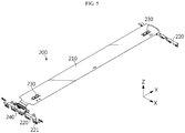
- FIG. 5 is a perspective view showing a FPCB assembly applied to the battery module according to an embodiment of the present disclosure
- FIG. 6 is a partially enlarged view showing a portion of the FPCB assembly depicted in FIG. 5
- FIG. 7 is an exploded perspective view for illustrating a coupling structure of a second FPCB and a connector applied to the present disclosure
- FIG. 8 is a diagram showing that the connector is coupled to the second FPCB applied to the present disclosure
- FIG. 9 is a diagram showing that the connector applied to the present disclosure is coupled to a bus bar frame.
- the FPCB assembly 200 may be implemented to include a first FPCB 210, a second FPCB 220, a temperature sensor 230 and a connector 240.
- the FPCB assembly 200 may be implemented to further include a stiffener 250 interposed between the second FPCB 220 and the connector 240.
- first FPCB 210 and the second FPCB 220 are described as components distinguished from each other, but the first FPCB 210 and the second FPCB 220 may be a single integrated flexible printed circuit board (FPCB). That is, the first FPCB 210 and the second FPCB 220 are just elements that are distinguished according to positions where they are disposed.
- FPCB flexible printed circuit board
- the first FPCB 210 extends along the longitudinal direction of the cell stack 100 (the Y-axis direction of FIGS. 4 and 5 ) to cover at least a portion of the upper surface of the cell stack 100.
- One longitudinal end of the first FPCB 210 is provided with a temperature sensor placing portion 211 formed by cutting a portion of the first FPCB 210.
- the temperature sensor 230 is mounted to the upper surface of the temperature sensor placing portion 211, whereby the temperature sensor 230 is installed at positions corresponding to both ends of the cell stack 100 in the longitudinal direction (the Y-axis of FIG. 4 ).
- the temperature sensor placing portion 211 is located at the center of the cell stack 100 in the width direction (the X-axis of FIG. 4 ). Accordingly, the temperature sensor 230 is installed at a position corresponding to the center of the cell stack 100 in the width direction.
- the position where the temperature sensor placing portion 211 is formed is selected to sense a temperature of a portion with the highest temperature in the cell stack 100.
- the FPCB assembly 200 may be connected to a control device that may control charging and discharging of the battery module, such as a battery management system (BMS). If the temperature of the battery module rises above a reference value, in order to ensure safety in use of the battery module, it is preferable to measure the temperature at a location with the highest temperature to control charging and discharging.
- BMS battery management system
- both longitudinal ends closest to the electrode lead 111 become optimal positions, and in the width direction of the cell stack 100 (the X-axis direction of FIG. 4 ), the center where heat dissipation is most difficult becomes an optimal position.
- the temperature sensor placing portion 211 is formed by cutting a part of the first FPCB 210, and one of both longitudinal ends of the temperature sensor placing portion 211 is formed as a fixed end and the other is formed as a free end. In addition, both widthwise ends of the temperature sensor placing portion 211 are formed as free ends by cutting.
- the temperature sensor placing portion 211 may move up and down freely despite the characteristics of the FPCB having a certain degree of stiffness. Accordingly, the temperature sensor 230 mounted to the temperature sensor placing portion 211 is indirectly adhered to the cell stack 100 through the temperature sensor placing portion 211, thereby accurately measuring the temperature of the cell stack 100.
- the second FPCB 220 is provided in a pair, and the second FPCBs 220 extend from both longitudinal ends of the first FPCB 210 and are electrically connected to a bus bar 320, explained later, respectively. That is, the second FPCB 220 has a plurality of connection terminals 221 formed at several branched ends, and the plurality of connection terminals 221 are connected to a plurality of bus bar 320, explained later.
- the second FPCB 220 includes a connector mounting portion 222 for mounting the connector 240, and a plurality of pin insert holes 222a for connecting the connector 240 and the second FPCB 220 are formed in the connector mounting portion 222.
- the connector 240 is mounted on the connector mounting portion 222 of the second FPCB 220, and the connector 240 is electrically connected to the connection terminal 221 through the FPCB.
- a control device such as BMS is connected to the connector 240, and the control device receives information about a voltage of the battery cell 110 measured through the bus bar 320 and the connection terminal 221, information about a temperature of the cell stack 100 measured through the temperature sensor 230, or the like, and controls charging and discharging of the battery module with reference to the information.
- the connector 240 includes a plurality of connector pins 241 for electrical connection with the second FPCB 220 and a fixing portion 242 for fixing with the bus bar frame 310.
- the plurality of connector pins 241 are inserted into the pin insert holes 222a formed in the connector mounting portion 222 of the second FPCB 220, fixed to the second FPCB 220 by welding at the rear side of the connector mounting portion 222, and also electrically connected to the second FPCB 220 .
- the fixing portion 242 may be provided in a pair at both sides of the connector 240, and includes a fixing hole 242a into which a fixing pin 313 provided to the bus bar frame 310, explained later, is inserted.
- the fixing pin 313 is thermally fused in a state of being inserted into the fixing hole 242a, so that the connector 240 is fixed to the bus bar frame 310.
- the stiffener 250 may be inserted between the second FPCB 220 and the connector 240.
- the stiffener 250 is provided to prevent that the welding portion between the connector pin 241 and the connector mounting portion 222 is damaged by vibration or the like due to the characteristics of the FPCB having relatively large ductility to break the electrical connection.
- the stiffener 250 includes a plurality of perforation holes 250a formed at positions corresponding to the connector pins 241 and the pin insert holes 222a with a size and shape corresponding thereto, and the connector pin 241 passes through the perforation hole 250a and the pin insert hole 222a and is then fixed to the second FPCB 220 by welding at the rear side of the second FPCB 220.
- the stiffener 250 may be made of a material such as a reinforced resin in consideration of the purpose of preventing damage to components caused by vibration while having non-conductivity in order to ensure insulation between the plurality of connector pins 241.
- FIG. 10 is a partially enlarged view showing the battery module of FIG. 1
- FIG. 11 is a side view showing the battery module of FIG. 10 , observed from one side.
- the connector 240 mounted on the second FPCB 220 faces a front surface (a surface parallel to the X-Z plane of FIG. 10 ) of the cell stack 100 but is installed in a space formed above the electrode lead 111 due to biasing of the electrode lead 111. That is, the connector 240 is installed to face an upper portion of the front surface of the cell stack 100.
- the connector 240 is installed in the space provided due to the structure in which the electrode lead 111 is installed to be biased, which minimizes the overall volume increase of the battery module caused by the installation of the connector 240, thereby improving energy density.
- bus bar frame assembly 300 and the outer terminal 400 applied to the present disclosure will be described in detail with reference to FIGS. 9 to 11 .
- the bus bar frame assembly 300 may be implemented to include a bus bar frame 310 configured to cover one longitudinal end and the other longitudinal end of the cell stack 100 and a plurality of bus bars 320 fixed on the bus bar frame 310 and electrically connected to the battery cells 110.
- the bus bar frame 310 may be made of an insulating material such as resin, and includes a bus bar placing portion 311 formed to protrude at a position corresponding to electrode leads 111 of the battery cell 110.
- the bus bar placing portion 311 is formed at a position biased downward from the center of the cell stack 100 in the height direction (the Z-axis direction of FIGS. 10 and 11 ), like the electrode lead 111.
- the biasing of the bus bar placing portion 311 is to secure a space for installing components, similar to the biasing of the electrode lead 111.
- the bus bar placing portion 311 has a plurality of lead slits S formed at positions corresponding to the electrode leads 111. Through the lead slits S, the electrode leads 111 are drawn out of the bus bar frame assembly 300, and the drawn electrode leads 111 are bent and fixed by welding or the like on the bus bar 320.
- the bus bar frame 310 has an FPCB placing portion 312 on which the second FPCB 220 is placed in a state where the connector 240 is mounted thereto.
- the FPCB placing portion 312 is located above the bus bar placing portion 311 (in an upper direction along the Z-axis of FIG. 10 ), but is located at the center of the cell stack 100 in the width direction (the X-axis direction of FIG. 10 ).
- the FPCB placing portion 312 is provided in a space formed above the electrode lead 111 and the bus bar placing portion 311 due to the biasing of the electrode lead 111, thereby minimizing the increase in volume of the battery module caused by the installation of the connector 240.
- the bus bar frame 310 includes a fixing pin 313 for fixing the connector 240.
- the fixing pin 313 is inserted into the fixing hole 242a formed in the fixing portion 242 of the connector 240, and an end of the fixing pin 313 is joined to the fixing portion 242 by thermal fusion so that the connector 240 may be fixed to the bus bar frame 310.
- the outer terminal 400 is provided in a pair, and the outer terminals 400 are respectively connected to the bus bars 320 located at outsides of the both sides of the cell stack 100 in the width direction (the X-axis direction of FIG. 10 ).
- the outer terminal 400 is located in the space formed above the electrode lead 111 and the bus bar placing portion 311 due to the biasing of the electrode lead 111 and the bus bar placing portion 311.
- the location where the outer terminal 400 is formed may minimize the increase in volume of the battery module caused by installing the outer terminal 400 since it utilizes the space formed by the biasing of the electrode lead 111.
- the upper cover 500 corresponds to a component that covers an upper surface of the cell stack 100 (a surface parallel to the X-Y plane of FIGS. 1 and 10 ) and the first FPCB 210.
- the upper cover 500 is hinged to the pair of bus bar frames 310, respectively, and a gap is formed at a location corresponding to the connection portion of the first FPCB 210 and the second FPCB 220, so that the connection portion of the first FPCB 210 and the second FPCB 220 is drawn out of the upper cover 500 through the gap.
- the connector 240 and the outer terminal 400 are installed using the space formed above the electrode lead 111 due to biasing of the electrode lead 111, thereby minimizing the increase in volume of the battery module caused by the installation of components and thus improving the energy density.
- the connector 240 is directly mounted to the FPCB using the pins provided to the connector 240 without performing the process of forming a separate terminal at the FPCB, it is possible to simplify the process for installing the connector 240 and remove the possibility of poor contact between the connector 240 and the FPCB, thereby improving the quality of the battery module.
Landscapes
- Chemical & Material Sciences (AREA)
- Chemical Kinetics & Catalysis (AREA)
- Electrochemistry (AREA)
- General Chemical & Material Sciences (AREA)
- Engineering & Computer Science (AREA)
- Manufacturing & Machinery (AREA)
- Microelectronics & Electronic Packaging (AREA)
- Connection Of Batteries Or Terminals (AREA)
- Battery Mounting, Suspending (AREA)
- Secondary Cells (AREA)
Abstract
Description
- The present disclosure relates to a battery module including a connector mounted on a FPCB, and a battery pack and a vehicle including the battery module, and more particularly, to a battery module including a connector mounted to both ends of a FPCB installed across a cell stack and provided using a space formed by biased arrangement of an electrode lead, and a battery pack and a vehicle including the battery module.
- The present application claims priority to Korean Patent Application No.
10-2018-0169964 filed on December 26, 2018 - A control device such as a battery management system (BMS) for controlling charging and discharging of a battery module by using information such as voltage of each battery cell and temperature of a cell stack of the battery module may be connected to the battery module. In order to connect the control device, it is necessary to install a connector that is electrically connected to each battery cell of the battery module and also electrically connected to a temperature sensor for measuring a temperature of the cell stack.
- Conventionally, in connecting a flexible printed circuit board (FPCB) used for electrical connection between components to a connector, after a terminal is compressed to the FPCB, an end of the FPCB at which the terminal is compressed is inserted and fixed into the connector.
- In this case, the process of compressing each terminal individually to the FPCB is required, which is not efficient in terms of productivity. Also, since the electrical connection between the FPCB and the connector is made using the terminal compressed to the FPCB, there is a high risk of contact failure when vibration or impact is applied thereto.
- In addition, even if one of various terminals has a contact failure with the FPCB or a compression failure occurs during the terminal compressing process, an error may occur in voltage measurement of the battery cell.
- Thus, there is a need to improve the connection structure between the FPCB and the connector in order to solve the above problems of deteriorated productivity and increased defect rate.
- In addition, due to the space occupied by the connector installed to sense a voltage or the like of each battery cell, the entire volume of the battery module is inevitably increased. If the volume of the battery module is increased without increasing the capacity of the cell stack, there is a loss in terms of energy density.
- Thus, there is a demand for a structural improvement capable of minimizing the increase in volume of the battery module caused by installing the connector.
- The present disclosure is designed to solve the problems of the related art, and therefore the present disclosure is directed to enhancing the structure for electrical connection between a FPCB and a connector to improve productivity and reduce defect rate, and also minimizing the increase in volume of a battery module caused by installing the connector.
- However, the technical problem to be solved by the present disclosure is not limited to the above, and other objects not mentioned herein will be understood from the following description by those skilled in the art.
- In one aspect of the present disclosure, there is provided a battery module, comprising: a cell stack formed by stacking a plurality of battery cells; a bus bar frame assembly including a bus bar frame configured to cover one longitudinal end and the other longitudinal end of the cell stack and a plurality of bus bars fixed on the bus bar frame and electrically connected to the battery cells; and a FPCB assembly including a first FPCB extending along a longitudinal direction of the cell stack to cover at least a portion of an upper surface of the cell stack, a second FPCB extending from one longitudinal end of the first FPCB and electrically connected to the bus bars, and a connector having a connector pin inserted into a pin insert hole formed in the second FPCB.
- The battery cell may include an electrode assembly; a pair of electrode leads connected to the electrode assembly and extending in opposite directions along a longitudinal direction of the battery cell; and a cell case configured to accommodate the electrode assembly and sealed to expose the electrode lead to the outside.
- The pair of electrode leads may be formed at locations biased downward from a center of the cell stack in a height direction.
- The bus bar frame may have a FPCB placing portion provided in a space formed above the electrode lead due to biasing of the electrode lead.
- The second FPCB may include a connector mounting portion placed on the FPCB placing portion and having the pin insert hole.
- The connector may be mounted on the connector mounting portion.
- The bus bar frame may have a fixing pin provided in the space formed above the electrode lead due to biasing of the electrode lead.
- The connector may have a fixing portion in which a fixing hole is formed so that the fixing pin is inserted therein.
- The FPCB assembly may comprise a stiffener interposed between the connector and the connector mounting portion and having a perforation hole formed at a location corresponding to the connector pin and the pin insert hole.
- Meanwhile, in another aspect of the present disclosure, there are also provided a battery pack and a vehicle, which comprises the battery module according to an embodiment of the present disclosure.
- According to an embodiment of the present disclosure, it is possible to improve productivity and reduce defect rate by enhancing the structure for electrical connection between a FPCB and a connector, and the increase in volume of the battery module caused by installing the connector may be minimized.
- The accompanying drawings illustrate a preferred embodiment of the present disclosure and together with the foregoing disclosure, serve to provide further understanding of the technical features of the present disclosure, and thus, the present disclosure is not construed as being limited to the drawing.
-
FIG. 1 is a perspective view showing a battery module according to an embodiment of the present disclosure. -
FIG. 2 is a perspective view showing a cell stack applied to the battery module according to an embodiment of the present disclosure. -
FIG. 3 is a plan view showing a battery cell applied to the battery module according to an embodiment of the present disclosure. -
FIG. 4 is a perspective view showing the battery module according to an embodiment of the present disclosure, from which an upper cover is eliminated. -
FIG. 5 is a perspective view showing a FPCB assembly applied to the battery module according to an embodiment of the present disclosure. -
FIG. 6 is a partially enlarged view showing a portion of the FPCB assembly depicted inFIG. 5 . -
FIG. 7 is an exploded perspective view for illustrating a coupling structure of a second FPCB and a connector applied to the present disclosure. -
FIG. 8 is a diagram showing that the connector is coupled to the second FPCB applied to the present disclosure. -
FIG. 9 is a diagram showing that the connector applied to the present disclosure is coupled to a bus bar frame. -
FIG. 10 is a partially enlarged view showing the battery module ofFIG. 1 . -
FIG. 11 is a side view showing the battery module ofFIG. 10 , observed from one side. - Hereinafter, preferred embodiments of the present disclosure will be described in detail with reference to the accompanying drawings. Prior to the description, it should be understood that the terms used in the specification and the appended claims should not be construed as limited to general and dictionary meanings, but interpreted based on the meanings and concepts corresponding to technical aspects of the present disclosure on the basis of the principle that the inventor is allowed to define terms appropriately for the best explanation. Therefore, the description proposed herein is just a preferable example for the purpose of illustrations only, not intended to limit the scope of the disclosure, so it should be understood that other equivalents and modifications could be made thereto without departing from the scope of the disclosure.
- First, the overall configuration of a battery module according to an embodiment of the present disclosure will be described with reference to
FIGS. 1 to 4 . -
FIG. 1 is a perspective view showing a battery module according to an embodiment of the present disclosure, andFIG. 2 is a perspective view showing a cell stack applied to the battery module according to an embodiment of the present disclosure. Also,FIG. 3 is a plan view showing a battery cell applied to the battery module according to an embodiment of the present disclosure, andFIG. 4 is a perspective view showing the battery module according to an embodiment of the present disclosure, from which an upper cover is eliminated. - Referring to
FIGS. 1 to 4 , a battery module according to an embodiment of the present disclosure may be implemented to include acell stack 100, aFPCB assembly 200, a busbar frame assembly 300, anouter terminal 400 and anupper cover 500. - The
cell stack 100 includes a plurality ofbattery cells 110 stacked to face each other at wide surfaces thereof. Thecell stack 100 may include at least one buffer pad P interposed at anoutermost battery cell 110 and/or betweenadjacent battery cells 110. - That is, the
cell stack 100 may be inserted into a mono frame (not shown) in a state of being coupled with theFPCB assembly 200, the busbar frame assembly 300, theouter terminal 400 and theupper cover 500. At this time, in order to insert thecell stack 100 easily while securing a maximum volume of thecell stack 100, the buffer pad P made of an elastic material such as a sponge may be additionally applied. - A pouch-type battery cell may be applied as the
battery cell 110. Referring toFIG. 3 , the pouch-type battery cell 110 includes an electrode assembly (not shown), a pair of electrode leads 111 and acell case 112. - Although not shown in the drawings, the electrode assembly has a form in which separators are interposed between positive electrode plates and negative electrode plates that are repeatedly stacked alternately, and separators are preferably positioned at both outermost sides for insulation, respectively.
- The positive electrode plate includes a positive electrode current collector and a positive electrode active material layer coated on one side of the positive electrode current collector, and a positive electrode uncoated region not coated with a positive electrode active material is formed at one side end of the positive electrode plate. The positive electrode uncoated region functions as a positive electrode tab.
- The negative electrode plate includes a negative electrode current collector and a negative electrode active material layer coated on one surface or both sides of the negative electrode current collector, and a negative electrode uncoated region not coated with a negative electrode active material is formed at one side end of the negative electrode plate. The negative electrode uncoated region functions as a negative electrode tab.
- In addition, the separator is interposed between the positive electrode plate and the negative electrode plate to prevent electrode plates having different polarities from directly contacting each other. The separator may be made of a porous material so that ions may be moved using the electrolyte as a medium between the positive electrode plate and the negative electrode plate.
- The pair of electrode leads 111 are connected to the positive electrode tab (not shown) and the negative electrode tab (not shown), respectively, and are drawn out of the
cell case 112. The pair of electrode leads 111 are drawn out at one longitudinal side and the other longitudinal side of thebattery cell 110, respectively. That is, thebattery cell 110 applied to the present disclosure corresponds to a bidirectional draw-out battery cell in which the positive electrode lead and the negative electrode lead are drawn in opposite directions. - In addition, the pair of electrode leads 111 are positioned to be biased to one side from a center of the
battery cell 110 in a width direction (the Z-axis direction ofFIG. 3 ). Specifically, the pair of electrode leads 111 are positioned to be biased to one side from the center of thebattery cell 110 in the width direction, preferably to be biased downward along the height direction (the Z-axis direction ofFIG. 2 ) of thecell stack 100. - If the pair of electrode leads 111 are positioned to be biased to one side from the center of the
battery cell 110 in the width direction as described above, it is possible to give a space for installation of a connector 240 (seeFIG. 5 ), explained later, and an outer terminal (seeFIG. 1 ) so that the energy density of the battery module is improved. The increase in energy density due to the structure in which theelectrode lead 111 is installed to be biased will be described in detail later. - The
cell case 112 includes two regions, namely an accommodation portion accommodating the electrode assembly and a sealing portion extending in a circumferential direction of the accommodation portion and thermally fused in a state where theelectrode lead 111 is drawn out to seal thecell case 112. - Although not shown in the figures, the
cell case 112 is sealed by affixing and thermally fusing edge portions of an upper case and a lower case made of a multi-layered pouch film in which a resin layer, a metal layer and a resin layer are stacked in order. - In the sealing portion, a
terrace portion 112a corresponding to a region located in the direction in which theelectrode lead 111 is drawn out has a tapered shape such that both sides of theterrace portion 112a are cut so that the width thereof is gradually reduced along the drawing direction of theelectrode lead 111. As described above, if the width of theterrace portion 112a is gradually reduced toward the outer side of thebattery cell 110, theelectrode lead 111 may be disposed to be biased, and the energy density of the battery module may be improved. - Meanwhile, the
battery cell 110 applied to the present disclosure is a long cell where a ratio of length (L) to width (W) is about 3 or more and 12 or less. In the battery module according to the present disclosure, if the long celltype battery cell 110 is employed, it is possible to improve the capacity of the battery while minimizing the increase in the height of the battery module, which makes it easy to install the battery module at a lower part of a seat or a trunk of a vehicle. - Next, the
FPCB assembly 200 will be described in detail with reference toFIGS. 5 to 9 along withFIG. 4 . -
FIG. 5 is a perspective view showing a FPCB assembly applied to the battery module according to an embodiment of the present disclosure, andFIG. 6 is a partially enlarged view showing a portion of the FPCB assembly depicted inFIG. 5 . Also,FIG. 7 is an exploded perspective view for illustrating a coupling structure of a second FPCB and a connector applied to the present disclosure,FIG. 8 is a diagram showing that the connector is coupled to the second FPCB applied to the present disclosure, andFIG. 9 is a diagram showing that the connector applied to the present disclosure is coupled to a bus bar frame. - Referring to
FIGS. 4 to 9 , theFPCB assembly 200 may be implemented to include afirst FPCB 210, asecond FPCB 220, atemperature sensor 230 and aconnector 240. In addition, theFPCB assembly 200 may be implemented to further include astiffener 250 interposed between thesecond FPCB 220 and theconnector 240. - In the present disclosure, the
first FPCB 210 and thesecond FPCB 220 are described as components distinguished from each other, but thefirst FPCB 210 and thesecond FPCB 220 may be a single integrated flexible printed circuit board (FPCB). That is, thefirst FPCB 210 and thesecond FPCB 220 are just elements that are distinguished according to positions where they are disposed. - The
first FPCB 210 extends along the longitudinal direction of the cell stack 100 (the Y-axis direction ofFIGS. 4 and5 ) to cover at least a portion of the upper surface of thecell stack 100. One longitudinal end of thefirst FPCB 210 is provided with a temperaturesensor placing portion 211 formed by cutting a portion of thefirst FPCB 210. - The
temperature sensor 230 is mounted to the upper surface of the temperaturesensor placing portion 211, whereby thetemperature sensor 230 is installed at positions corresponding to both ends of thecell stack 100 in the longitudinal direction (the Y-axis ofFIG. 4 ). In addition, the temperaturesensor placing portion 211 is located at the center of thecell stack 100 in the width direction (the X-axis ofFIG. 4 ). Accordingly, thetemperature sensor 230 is installed at a position corresponding to the center of thecell stack 100 in the width direction. - The position where the temperature
sensor placing portion 211 is formed is selected to sense a temperature of a portion with the highest temperature in thecell stack 100. TheFPCB assembly 200 may be connected to a control device that may control charging and discharging of the battery module, such as a battery management system (BMS). If the temperature of the battery module rises above a reference value, in order to ensure safety in use of the battery module, it is preferable to measure the temperature at a location with the highest temperature to control charging and discharging. - Thus, in the longitudinal direction of the cell stack 100 (the Y-axis direction of
FIG. 4 ), both longitudinal ends closest to theelectrode lead 111 become optimal positions, and in the width direction of the cell stack 100 (the X-axis direction ofFIG. 4 ), the center where heat dissipation is most difficult becomes an optimal position. - As shown in
FIG. 6 , the temperaturesensor placing portion 211 is formed by cutting a part of thefirst FPCB 210, and one of both longitudinal ends of the temperaturesensor placing portion 211 is formed as a fixed end and the other is formed as a free end. In addition, both widthwise ends of the temperaturesensor placing portion 211 are formed as free ends by cutting. - By doing so, the temperature
sensor placing portion 211 may move up and down freely despite the characteristics of the FPCB having a certain degree of stiffness. Accordingly, thetemperature sensor 230 mounted to the temperaturesensor placing portion 211 is indirectly adhered to thecell stack 100 through the temperaturesensor placing portion 211, thereby accurately measuring the temperature of thecell stack 100. - The
second FPCB 220 is provided in a pair, and thesecond FPCBs 220 extend from both longitudinal ends of thefirst FPCB 210 and are electrically connected to abus bar 320, explained later, respectively. That is, thesecond FPCB 220 has a plurality ofconnection terminals 221 formed at several branched ends, and the plurality ofconnection terminals 221 are connected to a plurality ofbus bar 320, explained later. - In addition, the
second FPCB 220 includes aconnector mounting portion 222 for mounting theconnector 240, and a plurality ofpin insert holes 222a for connecting theconnector 240 and thesecond FPCB 220 are formed in theconnector mounting portion 222. - The
connector 240 is mounted on theconnector mounting portion 222 of thesecond FPCB 220, and theconnector 240 is electrically connected to theconnection terminal 221 through the FPCB. As described above, a control device (not shown) such as BMS is connected to theconnector 240, and the control device receives information about a voltage of thebattery cell 110 measured through thebus bar 320 and theconnection terminal 221, information about a temperature of thecell stack 100 measured through thetemperature sensor 230, or the like, and controls charging and discharging of the battery module with reference to the information. - The
connector 240 includes a plurality of connector pins 241 for electrical connection with thesecond FPCB 220 and a fixingportion 242 for fixing with thebus bar frame 310. - The plurality of connector pins 241 are inserted into the
pin insert holes 222a formed in theconnector mounting portion 222 of thesecond FPCB 220, fixed to thesecond FPCB 220 by welding at the rear side of theconnector mounting portion 222, and also electrically connected to thesecond FPCB 220 . - The fixing
portion 242 may be provided in a pair at both sides of theconnector 240, and includes a fixinghole 242a into which afixing pin 313 provided to thebus bar frame 310, explained later, is inserted. The fixingpin 313 is thermally fused in a state of being inserted into the fixinghole 242a, so that theconnector 240 is fixed to thebus bar frame 310. - Meanwhile, as described above, the
stiffener 250 may be inserted between thesecond FPCB 220 and theconnector 240. Thestiffener 250 is provided to prevent that the welding portion between theconnector pin 241 and theconnector mounting portion 222 is damaged by vibration or the like due to the characteristics of the FPCB having relatively large ductility to break the electrical connection. - The
stiffener 250 includes a plurality ofperforation holes 250a formed at positions corresponding to the connector pins 241 and thepin insert holes 222a with a size and shape corresponding thereto, and theconnector pin 241 passes through theperforation hole 250a and thepin insert hole 222a and is then fixed to thesecond FPCB 220 by welding at the rear side of thesecond FPCB 220. - Meanwhile, the
stiffener 250 may be made of a material such as a reinforced resin in consideration of the purpose of preventing damage to components caused by vibration while having non-conductivity in order to ensure insulation between the plurality of connector pins 241. - Next, a specific arrangement position of the
connector 240 will be described with reference toFIGS. 10 and11 . -
FIG. 10 is a partially enlarged view showing the battery module ofFIG. 1 , andFIG. 11 is a side view showing the battery module ofFIG. 10 , observed from one side. - Referring to
FIGS. 10 and11 , theconnector 240 mounted on thesecond FPCB 220 faces a front surface (a surface parallel to the X-Z plane ofFIG. 10 ) of thecell stack 100 but is installed in a space formed above theelectrode lead 111 due to biasing of theelectrode lead 111. That is, theconnector 240 is installed to face an upper portion of the front surface of thecell stack 100. - As such, the
connector 240 is installed in the space provided due to the structure in which theelectrode lead 111 is installed to be biased, which minimizes the overall volume increase of the battery module caused by the installation of theconnector 240, thereby improving energy density. - Next, the bus
bar frame assembly 300 and theouter terminal 400 applied to the present disclosure will be described in detail with reference toFIGS. 9 to 11 . - Referring to
FIGS. 9 to 11 , the busbar frame assembly 300 may be implemented to include abus bar frame 310 configured to cover one longitudinal end and the other longitudinal end of thecell stack 100 and a plurality ofbus bars 320 fixed on thebus bar frame 310 and electrically connected to thebattery cells 110. - The
bus bar frame 310, for example, may be made of an insulating material such as resin, and includes a busbar placing portion 311 formed to protrude at a position corresponding to electrode leads 111 of thebattery cell 110. - The bus
bar placing portion 311 is formed at a position biased downward from the center of thecell stack 100 in the height direction (the Z-axis direction ofFIGS. 10 and11 ), like theelectrode lead 111. The biasing of the busbar placing portion 311 is to secure a space for installing components, similar to the biasing of theelectrode lead 111. - The bus
bar placing portion 311 has a plurality of lead slits S formed at positions corresponding to the electrode leads 111. Through the lead slits S, the electrode leads 111 are drawn out of the busbar frame assembly 300, and the drawn electrode leads 111 are bent and fixed by welding or the like on thebus bar 320. - The
bus bar frame 310 has anFPCB placing portion 312 on which thesecond FPCB 220 is placed in a state where theconnector 240 is mounted thereto. TheFPCB placing portion 312 is located above the bus bar placing portion 311 (in an upper direction along the Z-axis ofFIG. 10 ), but is located at the center of thecell stack 100 in the width direction (the X-axis direction ofFIG. 10 ). In addition, theFPCB placing portion 312 is provided in a space formed above theelectrode lead 111 and the busbar placing portion 311 due to the biasing of theelectrode lead 111, thereby minimizing the increase in volume of the battery module caused by the installation of theconnector 240. - The
bus bar frame 310 includes a fixingpin 313 for fixing theconnector 240. The fixingpin 313 is inserted into the fixinghole 242a formed in the fixingportion 242 of theconnector 240, and an end of the fixingpin 313 is joined to the fixingportion 242 by thermal fusion so that theconnector 240 may be fixed to thebus bar frame 310. - The
outer terminal 400 is provided in a pair, and theouter terminals 400 are respectively connected to the bus bars 320 located at outsides of the both sides of thecell stack 100 in the width direction (the X-axis direction ofFIG. 10 ). - Like the
connector 240 described above, theouter terminal 400 is located in the space formed above theelectrode lead 111 and the busbar placing portion 311 due to the biasing of theelectrode lead 111 and the busbar placing portion 311. The location where theouter terminal 400 is formed may minimize the increase in volume of the battery module caused by installing theouter terminal 400 since it utilizes the space formed by the biasing of theelectrode lead 111. - Next, the
upper cover 500 will be described with reference toFIGS. 1 and10 . - Referring to
FIGS. 1 and 1 , theupper cover 500 corresponds to a component that covers an upper surface of the cell stack 100 (a surface parallel to the X-Y plane ofFIGS. 1 and10 ) and thefirst FPCB 210. Theupper cover 500 is hinged to the pair of bus bar frames 310, respectively, and a gap is formed at a location corresponding to the connection portion of thefirst FPCB 210 and thesecond FPCB 220, so that the connection portion of thefirst FPCB 210 and thesecond FPCB 220 is drawn out of theupper cover 500 through the gap. - As described above, in the battery module according to the present disclosure, the
connector 240 and theouter terminal 400 are installed using the space formed above theelectrode lead 111 due to biasing of theelectrode lead 111, thereby minimizing the increase in volume of the battery module caused by the installation of components and thus improving the energy density. - In addition, in the battery module according to the present disclosure, since the
connector 240 is directly mounted to the FPCB using the pins provided to theconnector 240 without performing the process of forming a separate terminal at the FPCB, it is possible to simplify the process for installing theconnector 240 and remove the possibility of poor contact between theconnector 240 and the FPCB, thereby improving the quality of the battery module. - The present disclosure has been described in detail. However, it should be understood that the detailed description and specific examples, while indicating preferred embodiments of the disclosure, are given by way of illustration only, since various changes and modifications within the scope of the disclosure will become apparent to those skilled in the art from this detailed description.
Claims (11)
- A battery module, comprising:a cell stack formed by stacking a plurality of battery cells;a bus bar frame assembly including a bus bar frame configured to cover one longitudinal end and the other longitudinal end of the cell stack and a plurality of bus bars fixed on the bus bar frame and electrically connected to the battery cells; anda FPCB assembly including a first FPCB extending along a longitudinal direction of the cell stack to cover at least a portion of an upper surface of the cell stack, a second FPCB extending from one longitudinal end of the first FPCB and electrically connected to the bus bars, and a connector having a connector pin inserted into a pin insert hole formed in the second FPCB.
- The battery module according to claim 1,
wherein the battery cell includes:an electrode assembly;a pair of electrode leads connected to the electrode assembly and extending in opposite directions along a longitudinal direction of the battery cell; anda cell case configured to accommodate the electrode assembly and sealed to expose the electrode lead to the outside. - The battery module according to claim 2,
wherein the pair of electrode leads are formed at locations biased downward from a center of the cell stack in a height direction. - The battery module according to claim 3,
wherein the bus bar frame has a FPCB placing portion provided in a space formed above the electrode lead due to biasing of the electrode lead. - The battery module according to claim 4,
wherein the second FPCB includes a connector mounting portion placed on the FPCB placing portion and having the pin insert hole. - The battery module according to claim 5,
wherein the connector is mounted on the connector mounting portion. - The battery module according to claim 4,
wherein the bus bar frame has a fixing pin provided in the space formed above the electrode lead due to biasing of the electrode lead. - The battery module according to claim 7,
wherein the connector has a fixing portion in which a fixing hole is formed so that the fixing pin is inserted therein. - The battery module according to claim 5,
wherein the FPCB assembly further comprising a stiffener interposed between the connector and the connector mounting portion and having a perforation hole formed at a location corresponding to the connector pin and the pin insert hole. - A battery pack, comprising the battery module according to any one of claims 1 to 9.
- A vehicle, comprising the battery module according to any one of claims 1 to 9.
Applications Claiming Priority (2)
| Application Number | Priority Date | Filing Date | Title |
|---|---|---|---|
| KR1020180169964A KR102395683B1 (en) | 2018-12-26 | 2018-12-26 | A battery module having a connector mounted on an FPCB, a battery pack and a vehicle comprising the same |
| PCT/KR2019/018239 WO2020138869A1 (en) | 2018-12-26 | 2019-12-20 | Battery module having connector mounted on fpcb, and battery pack and vehicle comprising same |
Publications (2)
| Publication Number | Publication Date |
|---|---|
| EP3836285A1 true EP3836285A1 (en) | 2021-06-16 |
| EP3836285A4 EP3836285A4 (en) | 2021-11-03 |
Family
ID=71126589
Family Applications (1)
| Application Number | Title | Priority Date | Filing Date |
|---|---|---|---|
| EP19904880.2A Pending EP3836285A4 (en) | 2018-12-26 | 2019-12-20 | Battery module having connector mounted on fpcb, and battery pack and vehicle comprising same |
Country Status (6)
| Country | Link |
|---|---|
| US (1) | US11888125B2 (en) |
| EP (1) | EP3836285A4 (en) |
| JP (1) | JP7106675B2 (en) |
| KR (1) | KR102395683B1 (en) |
| CN (1) | CN112119532B (en) |
| WO (1) | WO2020138869A1 (en) |
Cited By (1)
| Publication number | Priority date | Publication date | Assignee | Title |
|---|---|---|---|---|
| EP4243190A1 (en) * | 2022-02-25 | 2023-09-13 | Molex, LLC | Battery connection module |
Families Citing this family (10)
| Publication number | Priority date | Publication date | Assignee | Title |
|---|---|---|---|---|
| USD974284S1 (en) * | 2018-12-26 | 2023-01-03 | Lg Energy Solution, Ltd. | Upper cover for battery module |
| CN209401680U (en) * | 2018-12-29 | 2019-09-17 | 宁德时代新能源科技股份有限公司 | Battery modules |
| JP7265443B2 (en) * | 2019-07-31 | 2023-04-26 | 日本航空電子工業株式会社 | wiring board assembly |
| CN112018291B (en) * | 2020-09-04 | 2022-08-30 | 重庆峘能电动车科技有限公司 | Battery box frame unit, battery box frame module and new energy automobile |
| KR20220114913A (en) | 2021-02-09 | 2022-08-17 | 주식회사 엘지에너지솔루션 | Battery module with a busbar frame for efficient lay-out of connector and battery pack including the same |
| KR20220135081A (en) * | 2021-03-29 | 2022-10-06 | 주식회사 엘지에너지솔루션 | Battery module and battery pack including the same |
| KR102642877B1 (en) * | 2021-05-21 | 2024-03-05 | 세방리튬배터리 주식회사 | Flexible printed circuit connector for battery |
| KR20230127074A (en) * | 2022-02-24 | 2023-08-31 | 주식회사 엘지에너지솔루션 | Flexible printed circuit board and secondary battery moudule including the same |
| KR20230163621A (en) | 2022-05-23 | 2023-12-01 | 삼원액트 주식회사 | Low-loss flat cable signal line for ultra-high frequency, flexible printed circuit board and flexible printed circuit board continuous manufacturing device using the same |
| KR20240003306A (en) | 2022-06-30 | 2024-01-08 | 에스케이온 주식회사 | Battery module |
Family Cites Families (23)
| Publication number | Priority date | Publication date | Assignee | Title |
|---|---|---|---|---|
| CA958845A (en) * | 1970-04-13 | 1974-12-03 | General Electric Company | Thermal oxidatively stable polycarbonate |
| KR100896134B1 (en) | 2005-06-23 | 2009-05-08 | 주식회사 엘지화학 | Battery Having Biased Electrode Terminals in Both Directions and Battery Pack Comprising the Same |
| KR20120003432A (en) | 2009-03-31 | 2012-01-10 | 산요덴키가부시키가이샤 | Battery module, battery system, and electric vehicle |
| US20130200700A1 (en) * | 2010-02-24 | 2013-08-08 | Sanyo Electric Co., Ltd. | Battery module, battery system, electric vehicle, movable body, power storage device, power supply device, and electrical equipment |
| JP5832819B2 (en) * | 2011-08-18 | 2015-12-16 | 大和製罐株式会社 | Assembled battery |
| JP2013143281A (en) | 2012-01-11 | 2013-07-22 | Auto Network Gijutsu Kenkyusho:Kk | Wiring module for battery |
| KR20140095660A (en) * | 2013-01-24 | 2014-08-04 | 엘지전자 주식회사 | Battery Cell Case And Battery Pack Comprising The Same |
| US10044018B2 (en) | 2013-09-06 | 2018-08-07 | Johnson Controls Technology Company | Battery module lid assembly system and method of making the same |
| US9123950B2 (en) | 2013-09-26 | 2015-09-01 | Lg Chem, Ltd. | Battery module and battery cell |
| KR20150144852A (en) | 2014-06-17 | 2015-12-29 | 주식회사 유라코퍼레이션 | Apparatus for connecting secondary cells in battery pack |
| KR101654997B1 (en) * | 2014-12-24 | 2016-09-06 | 엘지전자 주식회사 | Printed circuit board and a method for manufacturing the same |
| US10062886B2 (en) * | 2015-09-04 | 2018-08-28 | Apple Inc. | Integrated component cap and spacer for battery pack |
| KR101872834B1 (en) * | 2015-12-21 | 2018-06-29 | 주식회사 유라코퍼레이션 | Coupling structure for measuring battery of the same |
| KR102034208B1 (en) * | 2016-03-03 | 2019-10-18 | 주식회사 엘지화학 | Battery module, battery pack the battery module and vehicle comprising the battery pack |
| KR102102927B1 (en) | 2016-10-06 | 2020-04-21 | 주식회사 엘지화학 | Battery module, battery pack comprising the battery module and vehicle comprising the battery pack |
| WO2018124751A1 (en) * | 2016-12-27 | 2018-07-05 | 주식회사 유라코퍼레이션 | Flexible circuit board and frame assembly including same |
| WO2018124494A2 (en) * | 2016-12-27 | 2018-07-05 | 주식회사 유라코퍼레이션 | Bus bar assembly and frame assembly |
| PL3565022T3 (en) * | 2016-12-27 | 2021-10-04 | Yura Corporation Co., Ltd. | Flexible circuit board and frame assembly including same |
| KR102033003B1 (en) * | 2017-02-28 | 2019-10-16 | 주식회사 유라코퍼레이션 | Frame assembly |
| CN207800816U (en) * | 2017-12-13 | 2018-08-31 | 国联汽车动力电池研究院有限责任公司 | Power battery module signal pickup assembly |
| US20190305265A1 (en) * | 2018-03-27 | 2019-10-03 | Rivian Ip Holdings, Llc | Shear wall with integrated conductors |
| JP6820297B2 (en) * | 2018-07-31 | 2021-01-27 | 矢崎総業株式会社 | Circuit body with connector and bus module |
| KR102306042B1 (en) * | 2018-12-11 | 2021-09-27 | 주식회사 엘지에너지솔루션 | FPCB assembly for battery module and a method for manufacturing FPCB assembly and a battery module including the same |
-
2018
- 2018-12-26 KR KR1020180169964A patent/KR102395683B1/en active IP Right Grant
-
2019
- 2019-12-20 CN CN201980031313.4A patent/CN112119532B/en active Active
- 2019-12-20 JP JP2020559374A patent/JP7106675B2/en active Active
- 2019-12-20 EP EP19904880.2A patent/EP3836285A4/en active Pending
- 2019-12-20 US US17/055,419 patent/US11888125B2/en active Active
- 2019-12-20 WO PCT/KR2019/018239 patent/WO2020138869A1/en unknown
Cited By (1)
| Publication number | Priority date | Publication date | Assignee | Title |
|---|---|---|---|---|
| EP4243190A1 (en) * | 2022-02-25 | 2023-09-13 | Molex, LLC | Battery connection module |
Also Published As
| Publication number | Publication date |
|---|---|
| CN112119532B (en) | 2024-02-02 |
| JP7106675B2 (en) | 2022-07-26 |
| KR102395683B1 (en) | 2022-05-06 |
| EP3836285A4 (en) | 2021-11-03 |
| CN112119532A (en) | 2020-12-22 |
| US11888125B2 (en) | 2024-01-30 |
| US20210151804A1 (en) | 2021-05-20 |
| WO2020138869A1 (en) | 2020-07-02 |
| KR20200080074A (en) | 2020-07-06 |
| JP2021518983A (en) | 2021-08-05 |
Similar Documents
| Publication | Publication Date | Title |
|---|---|---|
| US11888125B2 (en) | Battery module having connector mounted on FPCB, and battery pack and vehicle comprising same | |
| US11302999B2 (en) | Unit module including busbar frame structure which can facilitate welding, and battery module including same | |
| EP3828986A1 (en) | Battery module structured so as to allow accurate temperature sensing, and battery pack and motor vehicle comprising same | |
| EP3783687A1 (en) | Battery module having structure in which energy density is improved, and battery pack and vehicle comprising same | |
| EP3787065A1 (en) | Battery module structured so as to prevent entry of foreign substances, and battery pack and motor vehicle comprising same | |
| EP2887427A1 (en) | Battery module with bus-bar holder | |
| US9099726B2 (en) | Secondary battery and method of fabricating the same | |
| US11152671B2 (en) | Battery module and battery pack including the same | |
| CN111801810B (en) | Battery module including inner lid | |
| EP3694015A1 (en) | Battery module having structure facilitating series-parallel connections and battery pack comprising same | |
| EP3836246A1 (en) | Battery module having guide for restricting movement of busbar frame, and battery pack and vehicle comprising same | |
| EP4135114A1 (en) | Battery module comprising solder pin for connection to busbar and battery pack including same | |
| JP2007080743A (en) | Power source device | |
| EP3930084B1 (en) | Connection assembly, battery module, battery pack, device, and manufacturing method | |
| US20220407196A1 (en) | Battery Module in Which Connection Between Electrode Lead and Voltage Sensing Member is Simplified, and Battery Pack Including the Same | |
| US11973244B2 (en) | Battery module having guide for restricting movement of busbar frame, and battery pack and vehicle comprising same | |
| US11978923B2 (en) | Battery module having structure in which energy density is improved, and battery pack and vehicle comprising same | |
| KR20220109031A (en) | Battery module and battery pack including the same |
Legal Events
| Date | Code | Title | Description |
|---|---|---|---|
| STAA | Information on the status of an ep patent application or granted ep patent |
Free format text: STATUS: THE INTERNATIONAL PUBLICATION HAS BEEN MADE |
|
| PUAI | Public reference made under article 153(3) epc to a published international application that has entered the european phase |
Free format text: ORIGINAL CODE: 0009012 |
|
| STAA | Information on the status of an ep patent application or granted ep patent |
Free format text: STATUS: REQUEST FOR EXAMINATION WAS MADE |
|
| 17P | Request for examination filed |
Effective date: 20210310 |
|
| AK | Designated contracting states |
Kind code of ref document: A1 Designated state(s): AL AT BE BG CH CY CZ DE DK EE ES FI FR GB GR HR HU IE IS IT LI LT LU LV MC MK MT NL NO PL PT RO RS SE SI SK SM TR |
|
| A4 | Supplementary search report drawn up and despatched |
Effective date: 20211001 |
|
| RIC1 | Information provided on ipc code assigned before grant |
Ipc: H01M 50/50 20210101ALI20210927BHEP Ipc: H05K 1/18 20060101ALI20210927BHEP Ipc: H05K 1/02 20060101ALI20210927BHEP Ipc: H01M 50/519 20210101ALI20210927BHEP Ipc: H01M 50/507 20210101ALI20210927BHEP Ipc: H01R 12/77 20110101ALI20210927BHEP Ipc: H01M 10/42 20060101AFI20210927BHEP |
|
| RAP1 | Party data changed (applicant data changed or rights of an application transferred) |
Owner name: LG ENERGY SOLUTION LTD. |
|
| RAP3 | Party data changed (applicant data changed or rights of an application transferred) |
Owner name: LG ENERGY SOLUTION, LTD. |
|
| DAV | Request for validation of the european patent (deleted) | ||
| DAX | Request for extension of the european patent (deleted) |