EP3835910A1 - Method for transferring a motor vehicle from a current position to a target position in an area separated from the general traffic - Google Patents
Method for transferring a motor vehicle from a current position to a target position in an area separated from the general traffic Download PDFInfo
- Publication number
- EP3835910A1 EP3835910A1 EP21155693.1A EP21155693A EP3835910A1 EP 3835910 A1 EP3835910 A1 EP 3835910A1 EP 21155693 A EP21155693 A EP 21155693A EP 3835910 A1 EP3835910 A1 EP 3835910A1
- Authority
- EP
- European Patent Office
- Prior art keywords
- motor vehicle
- vehicle
- information
- target path
- target
- Prior art date
- Legal status (The legal status is an assumption and is not a legal conclusion. Google has not performed a legal analysis and makes no representation as to the accuracy of the status listed.)
- Granted
Links
- 238000000034 method Methods 0.000 title claims abstract description 50
- 238000012546 transfer Methods 0.000 claims abstract description 12
- 230000005540 biological transmission Effects 0.000 claims abstract description 7
- 230000004888 barrier function Effects 0.000 claims abstract description 6
- 230000007613 environmental effect Effects 0.000 claims description 13
- 238000009826 distribution Methods 0.000 claims description 3
- 239000000446 fuel Substances 0.000 claims description 2
- 238000004891 communication Methods 0.000 description 13
- 238000004364 calculation method Methods 0.000 description 4
- 238000001514 detection method Methods 0.000 description 4
- 238000011161 development Methods 0.000 description 3
- 238000013459 approach Methods 0.000 description 2
- 230000006870 function Effects 0.000 description 2
- 238000004519 manufacturing process Methods 0.000 description 2
- 238000012545 processing Methods 0.000 description 2
- 238000003860 storage Methods 0.000 description 2
- 238000002604 ultrasonography Methods 0.000 description 2
- 240000004752 Laburnum anagyroides Species 0.000 description 1
- 230000006399 behavior Effects 0.000 description 1
- 238000007796 conventional method Methods 0.000 description 1
- 230000001419 dependent effect Effects 0.000 description 1
- 238000012544 monitoring process Methods 0.000 description 1
- 230000002123 temporal effect Effects 0.000 description 1
Images


Classifications
-
- G—PHYSICS
- G05—CONTROLLING; REGULATING
- G05D—SYSTEMS FOR CONTROLLING OR REGULATING NON-ELECTRIC VARIABLES
- G05D1/00—Control of position, course or altitude of land, water, air, or space vehicles, e.g. automatic pilot
- G05D1/02—Control of position or course in two dimensions
- G05D1/021—Control of position or course in two dimensions specially adapted to land vehicles
- G05D1/0287—Control of position or course in two dimensions specially adapted to land vehicles involving a plurality of land vehicles, e.g. fleet or convoy travelling
- G05D1/0291—Fleet control
- G05D1/0297—Fleet control by controlling means in a control room
Definitions
- the invention relates to a method for transferring, preferably for automated transferring, a motor vehicle from a current position to a target position in an area separated from general road traffic.
- a solution that is easy to implement is to be provided, with which a reliable and efficient determination of individual trajectories is made possible even when different vehicle types and vehicle classes are present.
- the method provides for a transfer, preferably an automated transfer, of a motor vehicle from a current position to a target position.
- the current position and the target position are located in an area separated from general traffic, preferably in an area separated by a barrier and / or gate system.
- this area can be, for example, a loading terminal for handling goods, a production facility or a managed storage area and / which can be an area that cannot be used by a random group of people due to the access restrictions that apply there.
- the motor vehicle to be transferred can be operated in an autonomous or partially autonomous first driving mode M 1 .
- the motor vehicle uses a driver assistance system to automatically guide the vehicle along a target path, including both longitudinal guidance and transverse guidance of the motor vehicle.
- the motor vehicle is only operated in this first driving mode M 1 in the area separated from general road traffic, ie, the approach to this area can be controlled by a human driver and only when staying in the named area, for example in the course of loading or unloading, is a change made to a driving mode in which the presence of a driver is no longer required.
- the method further comprises the steps of: determining a target path from the current position of the motor vehicle to the target position of the motor vehicle by the vehicle-external planning device. A transmission of the target path determined by the planning device external to the vehicle to the motor vehicle and a transfer of the motor vehicle from the current position to the target position in the first driving mode M 1 along the transmitted target path.
- the target path is therefore not determined by the motor vehicle itself, but by the planning device external to the vehicle. This is advantageous because the external planning device knows the possible routes in the area separated from general road traffic and can specify a target position for the motor vehicle, e.g. B. a free loading terminal.
- vehicle-specific parameters can first be transmitted from the motor vehicle to the planning unit before the corresponding trajectory is determined, on the basis of which the desired trajectory is then individually determined.
- different turning circles, degrees of automation and / or axle load distributions of the motor vehicles, but also any protruding loads can advantageously be taken into account when planning the route without additional sensor devices external to the vehicle being required to detect such parameters. Overall, this reduces operating costs and increases the accuracy and reliability of the determination of the trajectory.
- the method comprises the steps of: transmitting at least one piece of vehicle information relating to a property of the motor vehicle from the motor vehicle to a planning device external to the vehicle and determining a target path from the current position of the motor vehicle to the target position of the motor vehicle by the planning device external to the vehicle, wherein the target path is determined according to this exemplary embodiment taking into account the transmitted at least one vehicle information item.
- the motor vehicle has at least one interface for digital communication with devices external to the vehicle, by means of which the corresponding vehicle information and the target path can be exchanged between the planning device external to the vehicle and the motor vehicle.
- the vehicle can use a wireless WLAN interface or an interface based on a standard of the 3GPP project (3rd Generation Partnership Project (3GPP)), for example the 3rd generation (3G), the 4th generation (4G) or the 5th generation (5G).
- 3GPP 3rd Generation Partnership Project
- target path in the context of the present application can be understood to mean that the target path is a spatial trajectory, i. H. represents a movement path.
- target path can also be understood to mean that the target path comprises a spatial trajectory as well as temporal information. The latter can indicate at what point in time the vehicle should stop at a certain point along the trajectory.
- the time information can, however, also be provided, for example, in the form of a speed profile along the trajectory.
- the vehicle information relating to a property of the motor vehicle can be specific to the individual motor vehicle. However, they can also be specific to the general vehicle type and / or the general vehicle class.
- the vehicle information can be stored in a memory of the vehicle, for example in the form of parameters, or it can be recorded qualitatively or quantitatively by the vehicle by means of appropriate measuring devices, for example via an axle load sensor.
- the at least one item of vehicle information can include first information which specifies a dimension of the motor vehicle or from which a dimension of the motor vehicle can be derived.
- the first information can include a length, a width, a height, a wheelbase, a frame height, a frame length, an overhang length, a ground clearance and / or some other characteristic length dimension of the motor vehicle.
- the dimensions can relate to both a single vehicle and a vehicle combination or vehicle combination, for example an articulated train from a truck with a trailer.
- the accuracy and reliability of the target trajectory determination is advantageously improved, since for each motor vehicle individually impassable partial areas, for example, too narrow and / or too steep route sections, Bridges that are too low and / or curves that are too tight can be avoided or excluded from route planning.
- the at least one item of vehicle information can include a second item of information that characterizes an autonomous driving ability of the motor vehicle.
- the second information item can include a maximum degree of automation, a maximum autonomous drive level, a reversing ability and / or a permissible driving speed in the first driving mode M 1 .
- the permissible driving speed in the autonomous driving mode of the motor vehicle can be used, for example, for clocking the passage of narrow passages.
- vehicles with different levels of automation can also be transferred simultaneously on the same site in an advantageous manner.
- the at least one item of vehicle information can also include third information relating to a load status of the motor vehicle.
- the third item of information can indicate an item, a type, a weight and / or a distribution of a load of the motor vehicle and / or a type of a trailer of the motor vehicle.
- the method can include the step of transmitting at least one piece of environmental information detected by sensors from the motor vehicle to the planning device external to the vehicle. Furthermore, the target path of the current position of the motor vehicle in relation to the target position of the motor vehicle can be determined by the planning device external to the vehicle, taking into account this transmitted at least one piece of environmental information.
- the nowadays Environment sensors for example radar, lidar, ultrasound, infrared and / or camera systems, which are often installed as standard in motor vehicles, can be used.
- the claimed method can then comprise the following steps: transmitting at least one of a sensor device external to the vehicle from the sensor device to the planning device external to the vehicle, and determining the target path from the current position of the motor vehicle to the target position of the motor vehicle by the planning device external to the vehicle Consideration of the transmitted at least one information about the surroundings.
- the captured information about the surroundings is preferably not continuously sent to the planning device external to the vehicle, but only in the event that an obstacle has been detected.
- the at least one piece of environmental information recorded by the motor vehicle can be information relating to a detected obstacle.
- the obstacle can be, for example, a third-party vehicle detected by the motor vehicle, a pedestrian and / or an object lying on or adjacent to the roadway.
- the information relating to a detected obstacle can include a position, extent and / or change over time of the obstacle.
- the detection that an obstacle is present is usually possible with the sensor system, which is usually built in series, and the corresponding software of the assistance systems, this being done, for example, on the basis of the size of the detected object or its reflection behavior.
- This enables a reliable distinction to be made between non-critical objects (e.g. rain) and obstacles (e.g. another vehicle).
- the transmission of obstacle information to the planning device external to the vehicle advantageously improves route planning, since the obstacle information is also available for other vehicles when calculating the target path without the obstacles already having to be in the detection range of their respective sensors.
- the method according to a further aspect of the invention can include the step of determining whether a conflict situation, preferably a dangerous situation, is present when the motor vehicle is being transferred from the current position to the target position in the first driving mode M 1 along the transmitted target path, include.
- the conflict situation can preferably be an impending collision with an obstacle.
- the determination of whether there is a conflict situation can be carried out by the planning device external to the vehicle. In a particularly advantageous embodiment, however, the determination can also be carried out by the vehicle itself, as a result of which the volume of data between the vehicle and the planning device external to the vehicle can be reduced. In this case, the determination of a conflict situation preferably takes place continuously while the motor vehicle is being transferred from the current position to the target position. Overall, the safety and reliability of the method are increased in an advantageous manner.
- the updating can include a change in the spatial component of the target path, i. H. the trajectory, but also include a change in the time component.
- the latter can take place, for example, in the form of a slowdown, stop instruction or other change in the speed profile.
- the updating and / or re-determination of the target path can also be carried out by the motor vehicle itself or by the planning device external to the vehicle. In the latter case, the corresponding transmission of the information required for this is also provided. This additional safeguarding prevents vehicles from colliding with obstacles of all kinds in an advantageous manner, which in turn increases the safety and reliability of the method.
- the motor vehicle can be operated remotely in a second driving mode M 2.
- the motor vehicle is remotely controlled by an operator external to the vehicle in such a way that the operator external to the vehicle carries out at least part of the vehicle guidance of the motor vehicle himself.
- a human operator can influence the vehicle guidance essentially in real time without this operator having to be in the immediate vicinity of the vehicle.
- the remote control by means of Teleoperation take place. In this way, difficult or complex driving maneuvers can advantageously be carried out by a person, for example from an elevated position with better visibility.
- the motor vehicle can be operated by an operator external to the vehicle in the second driving mode M 2 if a conflict situation has been determined.
- a conflict situation has been determined.
- remote control can take place when a collision between two motor vehicles is imminent.
- a simultaneous, independent updating or recalculation of the target trajectories could result in an endless loop or a dead-end situation that can be circumvented by targeted short remote control of the vehicles.
- Further predetermined conflict situations can be, for example, passing a bottleneck, the failure of a sensor unit of the motor vehicle and / or the detection of a person in the vicinity of the motor vehicle.
- a broad aspect of the method according to the invention can provide that if there is at least one further motor vehicle in the area separated from general road traffic, the step of determining the target path of the motor vehicle by the vehicle-external planning device takes place independently of the step of determining the target path of the at least one further motor vehicle.
- Surrounding information, preferably location data, of the other vehicles can certainly be taken into account when determining the target path, but the target path is determined independently of that of the other vehicles.
- a global optimum of all target trajectories of the motor vehicles is not determined by a simultaneous determination or calculation of all routes, which is known to be a very computationally complex and complex problem in the case of several vehicles.
- the claimed independent determination of the desired trajectories is easy to implement in an advantageous manner and can thus also be used for the simultaneous transfer of a large number of motor vehicles.
- this aspect of the method also harbors the risk that conflict situations, for example collisions, can occur between the vehicles.
- Conflict monitoring and / or conflict resolution is therefore preferably also carried out, e.g. By teleoperation as described above.
- the target path of the motor vehicle can also be determined by the vehicle-external planning device, taking into account the transmitted environmental information of the at least one further motor vehicle.
- the environmental information recorded by the individual vehicles and transmitted to the planning device external to the vehicle is available when determining the target path for all vehicles.
- the target path of the motor vehicle can also be determined by the planning device external to the vehicle, taking into account the transmitted vehicle information from the at least one further motor vehicle. In this way, the desired path determination of all vehicles can be optimized in an advantageous manner, since information outside the actual information horizon of the individual vehicles is also available when the desired path is determined.
- each of the motor vehicles can have a, preferably logical, computing module of the vehicle-external Be assigned to a planning device that determines the target path for the respective motor vehicle.
- the planning device external to the vehicle can thus be viewed as a decentralized system.
- the individual computing modules can be designed in the form of logical sub-units of a central processing unit, but also as independent computers that do not have a common memory and only communicate with one another via messages. In order to enable communication between the individual computing modules, they can each include a corresponding interface, for example a network interface or a wireless WLAN interface. Overall, the independence of the decentralized computing modules advantageously increases the failure safety and reliability of the method.
- the at least one item of vehicle information can include fourth information that can relate to performance information of a drive train of the motor vehicle.
- the fourth item of information can relate to a maximum drive torque, an available engine power and / or gear shift times.
- the at least one piece of vehicle information can also or alternatively include a fifth piece of information that indicates fuel consumption of the motor vehicle as a function of the gear engaged, its load condition and / or its speed.
- a target path that is as fuel-efficient and / or energy-saving as possible can then be determined, as a result of which resources and operating costs can be saved in an advantageous manner.
- the at least one item of vehicle information can include sixth information that specifies the current position of the motor vehicle and / or from which the current position of the motor vehicle can be derived.
- the motor vehicle has a corresponding unit for determining position, for example a satellite-based navigation system, e.g. B. GPS has.
- the flexibility of the method can be increased in an advantageous manner, since the vehicles do not have to be parked in certain starting areas, for example.
- the area separated from general road traffic is private property and / or an area that cannot be used by a random group of people due to access restrictions.
- the area separated from general road traffic is a loading terminal for handling goods, a managed parking space and / or an area in which a maximum speed of 50 km / h, preferably 30 km / h, applies.
- the area mentioned can also be a storage area, a production area, an agriculturally used area, a mine area and / or a port area. All these restrictions advantageously ensure that the ambient conditions can be better controlled because, for example, only a certain number of people and / or motor vehicles can be allowed access to the operating area. This increases the overall security and feasibility of the method.
- FIG. 1 shows a flowchart of the method for transferring a motor vehicle 2a, 2b, 2c from a current position to a target position according to an embodiment of the invention.
- the method here comprises steps S21 to S24.
- step S21 at least one vehicle information item relating to a property of the motor vehicle 2a, 2b, 2c is transmitted from the motor vehicle 2a, 2b, 2c to a planning device 10 external to the vehicle. , characterize an autonomous driving ability of the motor vehicle (e.g. its maximum autonomous driving position), or a load condition of the motor vehicle (e.g. its weight).
- an autonomous driving ability of the motor vehicle e.g. its maximum autonomous driving position
- a load condition of the motor vehicle e.g. its weight
- the motor vehicle 2a, 2b, 2c can have a corresponding communication device 5a, 5b, 5c for wireless data exchange, for example in the form of a wireless WLAN interface, and the planning device 10 external to the vehicle can have its own corresponding communication device 9.
- a target path 4a, 4b, 4c from the current position of the motor vehicle 2a, 2b, 2c to the target position of the motor vehicle 2a, 2b, 2c is determined by the vehicle-external planning device 10, taking into account the transmitted at least one vehicle information item.
- the vehicle-external planning device 10 taking into account the transmitted at least one vehicle information item.
- the transmitted at least one vehicle information item representing an additional boundary condition.
- an individual route can be determined in an advantageous manner for the respective vehicle 2a, 2b, 2c, which avoids, for example, too narrow and / or too steep route sections, bridges that are too low and / or curves that are too narrow for this particular vehicle 2a, 2b, 2c .
- step S23 the target path 4a, 4b, 4c determined by the planning device 10 external to the vehicle is transmitted to the motor vehicle 2a, 2b, 2c. This can in turn take place via the corresponding vehicle communication device 5a, 5b, 5c and the communication device 9 external to the vehicle of the planning device 10.
- the motor vehicle 2a, 2b, 2c is then transferred from the current position to the target position in a first driving mode M 1 along this transmitted setpoint path 4a, 4b, 4c in step S24.
- the motor vehicle 2a, 2b, 2c automatically guides the motor vehicle 2a, 2b, 2c along the target path 4a, 4b, 4c, including both longitudinal guidance and lateral guidance of the motor vehicle 2a, 2b, 2c with the aid of a driver assistance system.
- the vehicle is transferred in an autonomous, ie fully automatic, or partially autonomous operation, in which the presence of a driver is preferably not required.
- FIG. 2 shows a flow chart of the claimed method according to a further embodiment of the invention.
- the steps S31a, S33 and S34 correspond to the steps S21, S22 and S24 of the previous embodiment in FIG Figure 1 .
- this variant also includes step S31b, in which at least one piece of environmental information recorded by sensors from the motor vehicle 2a, 2b, 2c is transmitted from the motor vehicle 2a, 2b, 2c to the planning device 10 external to the vehicle.
- the information about the surroundings can be, for example, a position, extent and / or change over time of a further vehicle 2a, 2b, 2c, a pedestrian or an object 7 lying on or adjacent to the roadway.
- Environment sensors 6a, 6b, 6c for example radar, lidar, ultrasound, infrared and / or camera systems, can often be used nowadays to acquire the information about the surroundings. In this way, changes on the routes in the from Area 1 separated from general road traffic, which the planning device 10 external to the vehicle is not or not yet known to, for example recognize an overturned container or an object lying on the route.
- step S32 in addition to the transmitted vehicle information, this captured environmental information is then used when determining the target path 4a, 4b, 4c from the current position of the motor vehicle 2a, 2b, 2c to the target position of the motor vehicle 2a, 2b, 2c by the vehicle-external planning device 10 considered.
- the target path 4a, 4b, 4c can thus be planned around an obstacle detected by a camera system of the motor vehicle 2a, 2b, 2c. This advantageously increases the security and reliability of the method.
- FIG. 3 A schematic representation of three motor vehicles 2a, 2b, 2c of different lengths, which are located in an area 1 separated from general road traffic, in this case a loading terminal for cargo handling, and are transferred to their respective target position according to one embodiment of the method, attests to this.
- Each of the three motor vehicles 2a, 2b, 2c can be operated autonomously and each comprises a sensor device for detecting the surroundings 6a, 6b, 6c and a communication device 5a, 5b, 5c for digital data exchange.
- the motor vehicles 2a, 2b, 2c are in contact with a planning device 10 external to the vehicle, which also has a corresponding communication device 9 for this purpose.
- the vehicle-external planning device 10 comprises three logic computing modules 3a, 3b, 3c, each of which is assigned to one of the motor vehicles 2a, 2b, 2c.
- the computation module 3a is used to determine the desired path of the vehicle 2a
- the computation module 3b to determine the desired path of the vehicle 2b
- the computation module 3c to determine the desired path of the vehicle 2c.
- the motor vehicle 2a After entering the area 1 separated from general traffic, the motor vehicle 2a transmits vehicle information relating to its length, height, type of load and degree of automation to the planning device 1 external to the vehicle, or more precisely to the computing module 3a assigned to this motor vehicle 2a. This then determines an individual target path 4a from the current one on the basis of the transmitted vehicle information and taking into account geodata of the loading area, the availability of individual terminals and the position of obstacles 7, which were transmitted from other motor vehicles 2b, 2c to the computer unit external to the vehicle Position of the motor vehicle 2a to that assigned by the computing module 3a Target position.
- the desired path 4a is determined independently of the determination of the desired paths 4b, 4c of the further motor vehicles 2b, 2c, which are also transferred using the same method according to the invention.
- On the basis of this independent determination during the transfer of the motor vehicle 2a to the target position there may be a risk of collisions with the other motor vehicles 2b, 2c on the loading site. For this reason, during the entire autonomous transfer of the motor vehicle 2a from the current position to the target position, the sensor device 6a of the motor vehicle 2a continuously monitors whether there is a collision with another vehicle 2b, 2c or another during the target path determination as yet unknown obstacle threatens.
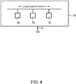
- FIG. 4 illustrates in a schematic representation again the decentralized exchange of environmental information between the computing modules 3a, 3b, 3c of the vehicle-external planning device 10 according to an embodiment of the invention.
- the computing modules 3a, 3b, 3c are designed as a decentralized system in the form of logical sub-units of a central computing unit.
- the computing modules 3a, 3b, 3c can, however, also be designed as independent computers that do not have a common memory and only communicate with one another via messages.
- the individual computing modules 3a, 3b, 3c are each assigned to only one motor vehicle 2a, 2b, 2c, communicate with the respective vehicle 2a, 2b, 2c via a common communication device 9.
- each of the computing modules 3a, 3b, 3c can also use a have their own communication facility.
- the individual computing modules 3a, 3b, 3c are in contact with one another via an interface for digital communication, in the present case a network interface, and exchange information about the surroundings that the respective computing modules 3a, 3b, 3c receive from their respectively assigned vehicles 2a, 2b, 2c received from.
- the computing modules 3a, 3b, 3c can also exchange vehicle information via the network that the respective computing modules 3a, 3b, 3c have received from their respectively assigned vehicles 2a, 2b, 2c.
- the target path determination of all vehicles can be optimized, since information outside the actual information horizon of the individual vehicles is also available when the target path is determined.
Abstract
Die Erfindung betrifft ein Verfahren zum Überführen, vorzugsweise zum automatisierten Überführen, eines Kraftfahrzeugs von einer aktuellen Position zu einer Zielposition, wobei sich sowohl die aktuelle Position als auch die Zielposition in einem vom allgemeinen Straßenverkehr, vorzugsweise durch eine Schranken- und/oder Toranlage, abgetrennten Bereich befinden. Ferner ist das zu überführende Kraftfahrzeug hierzu in einem autonomen oder teil-autonomen ersten Fahrmodus M<sub>1</sub> betreibbar. In diesem führt das Kraftfahrzeug mithilfe eines Fahrerassistenzsystems selbsttätig sowohl eine Längsführung als auch eine Querführung des Kraftfahrzeugs umfassende Fahrzeugführung entlang einer Soll-Bahn durch. Erfindungsgemäß umfasst das Verfahren dabei die Schritte: Übermitteln mindestens einer Fahrzeuginformation, betreffend eine Eigenschaft des Kraftfahrzeugs, vom Kraftfahrzeug an eine fahrzeugexterne Planungseinrichtung. Bestimmen einer Soll-Bahn von der aktuellen Position des Kraftfahrzeugs zur Zielposition des Kraftfahrzeugs durch die fahrzeugexterne Planungseinrichtung unter Berücksichtigung der übermittelten mindestens einen Fahrzeuginformation. Übermitteln der von der fahrzeugexternen Planungseinrichtung bestimmten Soll-Bahn an das Kraftfahrzeug und Überführen des Kraftfahrzeugs von der aktuellen Position zur Ziel-position im ersten Fahrmodus M1 entlang der übermittelten Soll-Bahn.The invention relates to a method for transferring, preferably for automated transfer, a motor vehicle from a current position to a target position, with both the current position and the target position being separated from general road traffic, preferably by a barrier and / or gate system Area. For this purpose, the motor vehicle to be transferred can also be operated in an autonomous or partially autonomous first driving mode M <sub> 1 </sub>. In this, the motor vehicle automatically performs both longitudinal guidance and transverse guidance of the motor vehicle along a target path with the aid of a driver assistance system. According to the invention, the method comprises the steps of: transmitting at least one item of vehicle information relating to a property of the motor vehicle from the motor vehicle to a planning device external to the vehicle. Determination of a target path from the current position of the motor vehicle to the target position of the motor vehicle by the planning device external to the vehicle, taking into account the transmitted at least one vehicle information item. Transmission of the target path determined by the planning device external to the vehicle to the motor vehicle and transferring the motor vehicle from the current position to the target position in the first driving mode M1 along the transmitted target path.
Description
Die Erfindung betrifft ein Verfahren zum Überführen, vorzugsweise zum automatisierten Überführen, eines Kraftfahrzeugs von einer aktuellen Position zu einer Zielposition in einem vom allgemeinen Straßenverkehr abgetrennten Bereich.The invention relates to a method for transferring, preferably for automated transferring, a motor vehicle from a current position to a target position in an area separated from general road traffic.
Im Stand der Technik sind grundsätzlich diverse Verfahren bekannt, um ein Kraftfahrzeug autonom oder teil-autonom von einem Startpunkt zu einem vorgegebenen Zielort zu bewegen. In der Praxis sind die meisten dieser Verfahren jedoch mit den heute auf dem Markt erhältlichen Kraftfahrzeugen nicht oder nur eingeschränkt durchführbar, da die meisten Fahrzeuge nicht über die hierfür nötigen Zusatzsysteme zur selbständiger Objekt- und Situationserkennung verfügen. Obwohl somit viele der heutigen Kraftfahrzeuge mittels der üblicherweise vorhandenen Assistenzsysteme (Tempomat, Lenkassistent, Bremsassistent etc.) - inklusive der zugehörigen Sensoren und Aktoren - zumindest theoretisch in der Lage wären, sich automatisiert zu bewegen bzw. einfach dazu umgerüstet werden könnten, scheitert ein Einsatz im allgemeinen Straßenverkehr aus technischer Sicht bislang meist an der Vielzahl an zu berücksichtigenden Szenarien, auf die es richtig zu reagieren gilt.In the prior art, various methods are known in principle for moving a motor vehicle autonomously or partially autonomously from a starting point to a predetermined destination. In practice, however, most of these methods cannot be carried out or can only be carried out to a limited extent with the motor vehicles available on the market today, since most vehicles do not have the necessary additional systems for independent object and situation recognition. Although many of today's motor vehicles would be able, at least in theory, to move automatically or simply be converted to do so using the assistance systems that are usually available (cruise control, steering assistants, brake assistants, etc.) - including the associated sensors and actuators - an application fails in general road traffic from a technical point of view so far mostly on the multitude of scenarios to be considered, to which one has to react correctly.
Anders stellt sich hingegen die Situation in vom allgemeinen Straßenverkehr abtrennten Bereichen, beispielsweise Verladeterminals, Lagerhallen oder landwirtschaftlich genutzten Flächen, dar. Aufgrund der dort herrschenden besser kontrollierbaren Umgebungsbedingungen in diesen Bereichen, scheint hier bereits in naher Zukunft mit den bestehenden Fahrzeugsystemen ein hoher Grad an Automatisierung erreicht werden zu können. In diesem Zusammenhang offenbart beispielsweise die Offenlegungsschrift
Im Rahmen der Erfindung wurde jedoch festgestellt, dass nachteilig an dieser Lösung ist, dass bei der Berechnung der Bewegungsbahn der Kraftfahrzeuge nicht explizit individuelle, d. h. fahrzeugspezifische, Kenngrößen, beispielsweise Fahrzeuglänge, Fahrzeugbreite oder Beladungszustand, berücksichtigt werden. Gerade dies ist allerdings für einen Einsatz eines derartigen Systems in Verladeterminals von Vorteil, da sich dort üblicherweise eine Vielzahl verschiedener Fahrzeuge (LKWs, LKWs mit Anhänger, Kleintransporter, Tankwägen etc.) mit entsprechend unterschiedlichen Wendekreisen, Schleppkurven und unterschiedlichem Platzbedarf aufhalten. Zudem führt die zentrale Berechnung der Bewegungsbahnen der Kraftfahrzeuge gemäß dem System der
Entsprechend ist es eine Aufgabe der Erfindung einen verbesserten Ansatz für ein zuverlässiges Überführen, vorzugsweise ein automatisiertes Überführen, eines Kraftfahrzeugs von einer aktuellen Position zu einer Zielposition bereitzustellen, mit dem Nachteile der herkömmlichen Techniken vermieden werden können. Insbesondere soll eine einfach zu implementierende Lösung bereitgestellt werden, mit der auch beim Vorhandensein unterschiedlicher Fahrzeugtypen und Fahrzeugklassen eine zuverlässige und effiziente Bestimmung individueller Bewegungsbahnen ermöglicht wird.Accordingly, it is an object of the invention to provide an improved approach for a reliable transfer, preferably an automated transfer, of a motor vehicle from a current position to a target position, with which the disadvantages of the conventional techniques can be avoided. In particular, a solution that is easy to implement is to be provided, with which a reliable and efficient determination of individual trajectories is made possible even when different vehicle types and vehicle classes are present.
Diese Aufgaben werden durch ein Verfahren mit den Merkmalen des unabhängigen Anspruchs gelöst. Vorteilhafte Ausführungsformen und Anwendungen der Erfindung sind Gegenstand der abhängigen Ansprüche und werden in der folgenden Beschreibung unter teilweiser Bezugnahme auf die Figuren näher erläutert.These objects are achieved by a method with the features of the independent claim. Advantageous embodiments and applications of the invention are the subject matter of the dependent claims and are explained in more detail in the following description with partial reference to the figures.
Das Verfahren sieht dabei ein Überführen, vorzugsweise ein automatisiertes Überführen, eines Kraftfahrzeugs von einer aktuellen Position zu einer Zielposition vor. Die aktuelle Position als auch die Zielposition befinden sich in einem vom allgemeinen Straßenverkehr abgetrennten Bereich, vorzugsweise in einem durch eine Schranken- und/oder Toranlage abgetrennten Bereich. Mit anderen Worten kann dieser Bereich beispielsweise ein Verladeterminal zum Güterumschlag, eine Produktionsanlage oder eine bewirtschaftete Stellfläche sein und/der ein Bereich sein, der aufgrund der dort geltenden Zugangsbeschränkungen nicht von einem zufälligen Personenkreis genutzt werden kann.The method provides for a transfer, preferably an automated transfer, of a motor vehicle from a current position to a target position. The current position and the target position are located in an area separated from general traffic, preferably in an area separated by a barrier and / or gate system. In other words, this area can be, for example, a loading terminal for handling goods, a production facility or a managed storage area and / which can be an area that cannot be used by a random group of people due to the access restrictions that apply there.
Ferner ist das zu überführende Kraftfahrzeug in einem autonomen oder teil-autonomen ersten Fahrmodus M1 betreibbar. In diesem führt das Kraftfahrzeug mithilfe eines Fahrerassistenzsystems selbsttätig eine, sowohl eine Längsführung als auch eine Querführung des Kraftfahrzeugs umfassende, Fahrzeugführung entlang einer Soll-Bahn durch. Dabei besteht die Möglichkeit, dass das Kraftfahrzeug erst auf dem vom allgemeinen Straßenverkehr abgetrennten Bereich in diesem ersten Fahrmodus M1 betrieben wird, d. h., die Anfahrt zu diesem Bereich kann von einem menschlichen Fahrer gesteuert erfolgen und erst beim Aufenthalt im genannten Bereich, beispielsweise im Zuge der Be- bzw. Entladung, wird in einen Fahrmodus gewechselt, in dem die Präsenz eines Fahrers nicht mehr erforderlich ist.Furthermore, the motor vehicle to be transferred can be operated in an autonomous or partially autonomous first driving mode M 1 . In this, the motor vehicle uses a driver assistance system to automatically guide the vehicle along a target path, including both longitudinal guidance and transverse guidance of the motor vehicle. There is the possibility that the motor vehicle is only operated in this first driving mode M 1 in the area separated from general road traffic, ie, the approach to this area can be controlled by a human driver and only when staying in the named area, for example in the course of loading or unloading, is a change made to a driving mode in which the presence of a driver is no longer required.
Das Verfahren umfasst ferner die Schritte: Bestimmen einer Soll-Bahn von der aktuellen Position des Kraftfahrzeugs zur Zielposition des Kraftfahrzeugs durch die fahrzeugexterne Planungseinrichtung. Ein Übermitteln der von der fahrzeugexternen Planungseinrichtung bestimmten Soll-Bahn an das Kraftfahrzeug und ein Überführen des Kraftfahrzeugs von der aktuellen Position zur Zielposition im ersten Fahrmodus M1 entlang der übermittelten Soll-Bahn.The method further comprises the steps of: determining a target path from the current position of the motor vehicle to the target position of the motor vehicle by the vehicle-external planning device. A transmission of the target path determined by the planning device external to the vehicle to the motor vehicle and a transfer of the motor vehicle from the current position to the target position in the first driving mode M 1 along the transmitted target path.
Die Soll-Bahn wird somit nicht durch das Kraftfahrzeug selbst, sondern von der fahrzeugexternen Planungseinrichtung bestimmt. Dies ist vorteilhaft, da die externe Planungseinrichtung die möglichen Fahrtstrecken in dem vom allgemeinen Straßenverkehr abgetrennten Bereich kennt und eine Zielposition für das Kraftfahrzeug vorgeben kann, z. B. ein freie Verladeterminal.The target path is therefore not determined by the motor vehicle itself, but by the planning device external to the vehicle. This is advantageous because the external planning device knows the possible routes in the area separated from general road traffic and can specify a target position for the motor vehicle, e.g. B. a free loading terminal.
Gemäß einem bevorzugten Ausführungsbeispiel der Erfindung können vor der Bestimmung der entsprechenden Bewegungsbahn zunächst fahrzeugspezifische Kenngrößen von dem Kraftfahrzeug an die Planungseinheit übermittelt werden, auf deren Basis dann die individuelle Bestimmung der Soll-Bahn erfolgt. Dadurch können auf vorteilhafte Weise unterschiedliche Wendekreise, Automatisierungsgrade und/oder Achslastverteilungen der Kraftfahrzeuge, aber auch eventuell überstehende Ladungen bei der Routenplanung berücksichtigt werden ohne dass zur Erfassung derartiger Parameter zusätzliche fahrzeugexterne Sensoreinrichtungen nötig sind. Insgesamt werden dadurch Betriebskosten reduziert sowie die Genauigkeit und Zuverlässigkeit der Bewegungsbahnbestimmung erhöht.According to a preferred exemplary embodiment of the invention, vehicle-specific parameters can first be transmitted from the motor vehicle to the planning unit before the corresponding trajectory is determined, on the basis of which the desired trajectory is then individually determined. As a result, different turning circles, degrees of automation and / or axle load distributions of the motor vehicles, but also any protruding loads, can advantageously be taken into account when planning the route without additional sensor devices external to the vehicle being required to detect such parameters. Overall, this reduces operating costs and increases the accuracy and reliability of the determination of the trajectory.
Gemäß diesem Ausführungsbeispiel umfasst das Verfahren hierzu die Schritte: ein Übermitteln mindestens einer Fahrzeuginformation, betreffend eine Eigenschaft des Kraftfahrzeugs, vom Kraftfahrzeug an eine fahrzeugexterne Planungseinrichtung und das Bestimmen einer Soll-Bahn von der aktuellen Position des Kraftfahrzeugs zur Zielposition des Kraftfahrzeugs durch die fahrzeugexterne Planungseinrichtung, wobei das Bestimmen der Soll-Bahn gemäß diesem Ausführungsbeispiel unter Berücksichtigung der übermittelten mindestens einen Fahrzeuginformation erfolgt.According to this exemplary embodiment, the method comprises the steps of: transmitting at least one piece of vehicle information relating to a property of the motor vehicle from the motor vehicle to a planning device external to the vehicle and determining a target path from the current position of the motor vehicle to the target position of the motor vehicle by the planning device external to the vehicle, wherein the target path is determined according to this exemplary embodiment taking into account the transmitted at least one vehicle information item.
Hierbei wird im Rahmen der vorliegenden Anmeldung davon ausgegangen, dass das Kraftfahrzeug über mindestens eine Schnittstelle zur digitalen Kommunikation mit fahrzeugexternen Einrichtungen verfügt, mittels der die entsprechenden Fahrzeuginformationen und die Soll-Bahn zwischen der fahrzeugexternen Planungseinrichtung und dem Kraftfahrzeug ausgetauscht werden können. Beispielsweise kann das Fahrzeug hierzu über eine drahtlose WLAN-Schnittstelle oder eine Schnittstelle basierend auch einem Standard des 3GPP-Projekts (3rd Generation Partnership Project (3GPP)), beispielsweise der 3. Generation (3G), der 4. Generation (4G) oder der 5. Generation (5G) verfügen.In the context of the present application, it is assumed that the motor vehicle has at least one interface for digital communication with devices external to the vehicle, by means of which the corresponding vehicle information and the target path can be exchanged between the planning device external to the vehicle and the motor vehicle. For example, the vehicle can use a wireless WLAN interface or an interface based on a standard of the 3GPP project (3rd Generation Partnership Project (3GPP)), for example the 3rd generation (3G), the 4th generation (4G) or the 5th generation (5G).
Der Begriff "Soll-Bahn" im Rahmen der vorliegenden Anmeldung kann so verstanden werden, dass die Soll-Bahn eine räumliche Trajektorie, d. h. einen Bewegungspfad, darstellt. Der Begriff "Soll-Bahn" kann ferner so verstanden werden, dass die Soll-Bahn eine räumliche Trajektorie als auch eine zeitliche Information umfasst. Letztere kann dabei angeben zu welchem Zeitpunkt sich das Fahrzeug an einem bestimmten Punkt entlang der Trajektorie aufhalten soll. Die zeitliche Information kann allerdings auch beispielsweise in Form eines Geschwindigkeitsprofils entlang der Trajektorie bereitgestellt werden.The term “target path” in the context of the present application can be understood to mean that the target path is a spatial trajectory, i. H. represents a movement path. The term “target path” can also be understood to mean that the target path comprises a spatial trajectory as well as temporal information. The latter can indicate at what point in time the vehicle should stop at a certain point along the trajectory. The time information can, however, also be provided, for example, in the form of a speed profile along the trajectory.
Ferner können die Fahrzeuginformationen, die eine Eigenschaft des Kraftfahrzeugs betreffend, spezifisch für das individuelle Kraftfahrzeug sein. Sie können allerdings auch spezifisch für den generellen Fahrzeugtyp und/oder die generelle Fahrzeugklasse sein. Darüber hinaus können die Fahrzeuginformationen in einem Speicher des Fahrzeugs, beispielsweise in Form von Kenngrößen, hinterlegt sein oder mittels entsprechender Messeinrichtungen, beispielsweise über einen Achslastsensor, qualitativ oder quantitativ vom Fahrzeug erfasst werden.Furthermore, the vehicle information relating to a property of the motor vehicle can be specific to the individual motor vehicle. However, they can also be specific to the general vehicle type and / or the general vehicle class. In addition, the vehicle information can be stored in a memory of the vehicle, for example in the form of parameters, or it can be recorded qualitatively or quantitatively by the vehicle by means of appropriate measuring devices, for example via an axle load sensor.
Gemäß einem weiteren Aspekt kann die mindestens eine Fahrzeuginformation eine erste Information umfassen, die eine Abmessung des Kraftfahrzeugs angibt oder aus der eine Abmessung des Kraftfahrzeugs ableitbar ist. Beispielsweise kann die erste Information eine Länge, eine Breite, eine Höhe, einen Radstand, eine Rahmenhöhe, eine Rahmenlänge, eine Überhanglänge, eine Bodenfreiheit und/oder ein sonstiges kennzeichnendes Längenmaß des Kraftfahrzeugs umfassen. Dabei kann die Abmessung sowohl ein Einzelfahrzeug als auch eine Fahrzeugkombination bzw. ein Fahrzeuggespann, beispielsweise ein Gliederzug aus einem Lastkraftwagen mit einem Anhänger, betreffen. Durch die Berücksichtigung derartiger Informationen bei der Bestimmung der Soll-Bahn wird auf vorteilhafte Weise die Genauigkeit und Zuverlässigkeit der Soll-Bahn-Bestimmung verbessert, da für jedes Kraftfahrzeug individuell unpassierbare Teilbereiche, beispielsweise, zu enge und/oder zu steile Streckenabschnitte, zu niedrige Brücken und/oder zu enge Kurven, gemieden bzw. von der Routenplanung ausgenommen werden können.According to a further aspect, the at least one item of vehicle information can include first information which specifies a dimension of the motor vehicle or from which a dimension of the motor vehicle can be derived. For example, the first information can include a length, a width, a height, a wheelbase, a frame height, a frame length, an overhang length, a ground clearance and / or some other characteristic length dimension of the motor vehicle. The dimensions can relate to both a single vehicle and a vehicle combination or vehicle combination, for example an articulated train from a truck with a trailer. By taking such information into account when determining the target trajectory, the accuracy and reliability of the target trajectory determination is advantageously improved, since for each motor vehicle individually impassable partial areas, for example, too narrow and / or too steep route sections, Bridges that are too low and / or curves that are too tight can be avoided or excluded from route planning.
Zudem oder alternativ kann die mindestens eine Fahrzeuginformation eine zweite Information umfassen, die eine autonome Fahrfähigkeit des Kraftfahrzeugs charakterisiert. Beispielsweise kann die zweite Information einen maximalen Automatisierungsgrad, eine maximale autonome Fahrstufe, eine Rückwärtsfahrfähigkeit und/oder eine zulässige Fahrgeschwindigkeit im ersten Fahrmodus M1 umfassen. Durch die Berücksichtigung derartiger Informationen bei der Bestimmung der Soll-Bahn lässt sich ebenfalls auf vorteilhafte Weise die Genauigkeit und Zuverlässigkeit der Soll-Bahn-Bestimmung verbessern, da die errechnete Stecke individuell an die jeweiligen Fahrzeugfähigkeiten angepasst werden kann. Beispielsweise können für Kraftfahrzeuge ohne autonome Rückfahrfunktion nur derartige Soll-Bahnen berechnet werden, bei welchen ein Rückwärtsfahren nicht notwendig ist. Zum anderen kann die zulässige Fahrgeschwindigkeit im autonomen Fahrmodus der Kraftfahrzeuge beispielsweise für die Taktung des Passierens von Engstellen verwendet werden. Durch die Berücksichtigung des maximalen Automatisierungsgrads bei der Soll-Bahn-Berechnung des Verfahrens können zudem auf vorteilhafte Weise auch Fahrzeuge mit verschiedenen Stufen der Automatisierung gleichzeitig auf demselben Gelände überführt werden.In addition or as an alternative, the at least one item of vehicle information can include a second item of information that characterizes an autonomous driving ability of the motor vehicle. For example, the second information item can include a maximum degree of automation, a maximum autonomous drive level, a reversing ability and / or a permissible driving speed in the first driving mode M 1 . By taking such information into account when determining the target path, the accuracy and reliability of the target path determination can also advantageously be improved, since the calculated route can be individually adapted to the respective vehicle capabilities. For example, for motor vehicles without an autonomous reversing function, only those target trajectories for which reversing is not necessary can be calculated. On the other hand, the permissible driving speed in the autonomous driving mode of the motor vehicle can be used, for example, for clocking the passage of narrow passages. By taking into account the maximum degree of automation in the target path calculation of the method, vehicles with different levels of automation can also be transferred simultaneously on the same site in an advantageous manner.
Zudem oder alternativ kann die mindestens eine Fahrzeuginformation auch eine dritte Information umfassen, die einen Beladungszustand des Kraftfahrzeugs betrifft. Beispielsweise kann die dritte Information eine Angabe, eine Art, ein Gewicht und/oder eine Verteilung einer Ladung des Kraftfahrzeugs und/oder eine Art eines Aufliegers des Kraftfahrzeugs angeben. Auch die Berücksichtigung derartiger Informationen bei der Bestimmung der Soll-Bahn trägt auf vorteilhafte Weise dazu bei, dass die Genauigkeit und Zuverlässigkeit der Soll-Bahn-Bestimmung verbessert wird, da Teilbereiche mit einem höchstzulässigen Gesamtgewicht, beispielsweise Brücken, oder zu steile Streckenabschnitte individuell gemieden bzw. von der Routenplanung ausgenommen werden können.In addition or as an alternative, the at least one item of vehicle information can also include third information relating to a load status of the motor vehicle. For example, the third item of information can indicate an item, a type, a weight and / or a distribution of a load of the motor vehicle and / or a type of a trailer of the motor vehicle. The consideration of such information when determining the target path also contributes in an advantageous manner to the fact that the accuracy and reliability of the target path determination is improved, since partial areas with a maximum permissible total weight, for example bridges, or too steep route sections are individually avoided or . Can be excluded from route planning.
Um die Bestimmung der Soll-Bahn noch weiter zu verbessern, kann das Verfahren nach einem weiteren Aspekt der Erfindung den Schritt des Übermittels mindestens einer vom Kraftfahrzeug sensorisch erfassten Umgebungsinformation vom Kraftfahrzeug an die fahrzeugexterne Planungseinrichtung umfassen. Ferner kann das Bestimmen der Soll-Bahn der aktuellen Position des Kraftfahrzeugs zur Zielposition des Kraftfahrzeugs durch die fahrzeugexterne Planungseinrichtung unter Berücksichtigung dieser übermittelten mindestens einen Umgebungsinformation erfolgen. Hierbei können zum Erfassen der Umgebungsinformation die heutzutage oftmals serienmäßig in Kraftfahrzeugen verbauten Umfeldsensoren, beispielsweise Radar-, Lidar-, Ultraschall-, Infrarot- und/oder Kamerasysteme genutzt werden. Auf vorteilhafte Weise lassen sich so Veränderungen auf den Strecken in dem vom allgemeinen Straßenverkehr abtrennten Bereich, die der fahrzeugexternen Planungseinrichtung nicht bzw. noch nicht bekannt sind, beispielsweise ein umgestürzter Container oder eine Ölspur, erkennen und bei der Soll-Bahn-Bestimmung berücksichtigen. Dadurch wird wiederum die Sicherheit und Zuverlässigkeit des Verfahrens erhöht, da die Soll-Bahnen um diese Hindernisse herum geplant werden können.In order to improve the determination of the target trajectory even further, according to a further aspect of the invention, the method can include the step of transmitting at least one piece of environmental information detected by sensors from the motor vehicle to the planning device external to the vehicle. Furthermore, the target path of the current position of the motor vehicle in relation to the target position of the motor vehicle can be determined by the planning device external to the vehicle, taking into account this transmitted at least one piece of environmental information. In this case, the nowadays Environment sensors, for example radar, lidar, ultrasound, infrared and / or camera systems, which are often installed as standard in motor vehicles, can be used. In an advantageous manner, changes on the routes in the area separated from general road traffic that are not or not yet known to the planning device external to the vehicle, for example an overturned container or an oil trail, can be recognized and taken into account when determining the target path. This in turn increases the safety and reliability of the method, since the target paths can be planned around these obstacles.
Zudem oder alternativ können auch durch fahrzeugexterne Sensoren erfasste und an die fahrzeugexterne Planungseinrichtung übermittelte Umgebungsinformationen bei der Soll-Bahn-Bestimmung berücksichtigt werden. Entsprechend kann dann das beanspruchte Verfahren dann die folgenden Schritte umfassen: ein Übermitteln mindestens von einer fahrzeugexternen Sensoreinrichtung erfassten Umgebungsinformation von der Sensoreinrichtung an die fahrzeugexterne Planungseinrichtung und ein Bestimmen der Soll-Bahn von der aktuellen Position des Kraftfahrzeugs zur Zielposition des Kraftfahrzeugs durch die fahrzeugexterne Planungseinrichtung unter Berücksichtigung der übermittelten mindestens einen Umgebungsinformation.In addition or as an alternative, environmental information recorded by sensors external to the vehicle and transmitted to the planning device external to the vehicle can also be taken into account when determining the target path. Correspondingly, the claimed method can then comprise the following steps: transmitting at least one of a sensor device external to the vehicle from the sensor device to the planning device external to the vehicle, and determining the target path from the current position of the motor vehicle to the target position of the motor vehicle by the planning device external to the vehicle Consideration of the transmitted at least one information about the surroundings.
Zur Vermeidung unnötigen Datenverkehrs werden vorzugsweise die erfassten Umgebungsinformationen allerdings nicht ständig an die fahrzeugexterne Planungseinrichtung übersandt, sondern nur im Falle, dass ein Hindernis erkannt wurde. Aus diesem Grund kann gemäß einer Weiterbildung der Erfindung die vom Kraftfahrzeug mindestens eine sensorisch erfasste Umgebungsinformation eine Informationen betreffend ein erfasstes Hindernis sein. Das Hindernis kann hierbei beispielsweise ein vom Kraftfahrzeug erfasstes Fremdfahrzeug, ein Fußgänger, und/oder ein auf der Fahrbahn liegendes oder angrenzendes Objekt sein. Ferner kann die Informationen betreffend ein erfasstes Hindernis eine Position, Ausdehnung und/oder zeitliche Veränderung des Hindernisses umfassen. Das Erkennen, dass ein Hindernis vorliegt, ist mit den meist serienmäßig verbauten Sensorsystem und der entsprechenden Software der Assistenzsysteme in der Regel möglich, wobei dies beispielsweise auf Basis der Größe des erfassten Objekts oder dessen Reflexionsverhaltens erfolgt. Dadurch kann zuverlässig zwischen unkritischen Objekten (z. B. Regen) und Hindernissen (z. B. ein anderes Fahrzeug) unterschieden werden. Die Übermittlung von Hindernisinformationen an die fahrzeugexterne Planungseinrichtung verbessert dabei auf vorteilhafte Weise die Routenplanung, da die Hindernis-Informationen so auch bei der Soll-Bahn-Berechnung anderer Fahrzeuge zur Verfügung steht ohne, dass sich die Hindernisse bereits im Erfassungsbereich ihrer jeweiligen Sensoren befinden müssen.In order to avoid unnecessary data traffic, however, the captured information about the surroundings is preferably not continuously sent to the planning device external to the vehicle, but only in the event that an obstacle has been detected. For this reason, according to a development of the invention, the at least one piece of environmental information recorded by the motor vehicle can be information relating to a detected obstacle. The obstacle can be, for example, a third-party vehicle detected by the motor vehicle, a pedestrian and / or an object lying on or adjacent to the roadway. Furthermore, the information relating to a detected obstacle can include a position, extent and / or change over time of the obstacle. The detection that an obstacle is present is usually possible with the sensor system, which is usually built in series, and the corresponding software of the assistance systems, this being done, for example, on the basis of the size of the detected object or its reflection behavior. This enables a reliable distinction to be made between non-critical objects (e.g. rain) and obstacles (e.g. another vehicle). The transmission of obstacle information to the planning device external to the vehicle advantageously improves route planning, since the obstacle information is also available for other vehicles when calculating the target path without the obstacles already having to be in the detection range of their respective sensors.
Zur weiteren Erhöhung der Sicherheit kann das Verfahren nach einem weiteren Aspekt der Erfindung den Schritt des Ermittelns, ob eine Konfliktsituation, vorzugsweise eine Gefahrensituation, beim Überführen des Kraftfahrzeugs von der aktuellen Position zur Zielposition im ersten Fahrmodus M1 entlang der übermittelten Soll-Bahn vorliegt, umfassen. Dabei kann die Konfliktsituation vorzugsweise eine drohende Kollision mit einem Hindernis sein. Das Ermitteln, ob eine Konfliktsituation vorliegt, kann dabei durch die fahrzeugexterne Planungseinrichtung erfolgen. In einer besonders vorteilhaften Ausführungsform kann das Ermitteln jedoch auch durch das Fahrzeug selbst erfolgen, wodurch das Datenaufkommen zwischen Fahrzeug und fahrzeugexterner Planungseinrichtung reduziert werden kann. Vorzugsweise erfolgt hierbei das Ermittelns einer Konfliktsituation ununterbrochen während des Überführen des Kraftfahrzeugs von der aktuellen Position zur Zielposition. Insgesamt wird so auf vorteilhafte Weise die Sicherheit und Zuverlässigkeit des Verfahrens erhöht.To further increase security, the method according to a further aspect of the invention can include the step of determining whether a conflict situation, preferably a dangerous situation, is present when the motor vehicle is being transferred from the current position to the target position in the first driving mode M 1 along the transmitted target path, include. The conflict situation can preferably be an impending collision with an obstacle. The determination of whether there is a conflict situation can be carried out by the planning device external to the vehicle. In a particularly advantageous embodiment, however, the determination can also be carried out by the vehicle itself, as a result of which the volume of data between the vehicle and the planning device external to the vehicle can be reduced. In this case, the determination of a conflict situation preferably takes place continuously while the motor vehicle is being transferred from the current position to the target position. Overall, the safety and reliability of the method are increased in an advantageous manner.
Gemäß einer Weiterbildung dieses Aspekts kann beim Vorliegen einer Konfliktsituation, weil z. B. ein Objekt die Fahrbahn versperrt, ein Aktualisieren und/oder Neu-Bestimmen der Soll-Bahn erfolgen. Dabei kann das Aktualisieren eine Änderung der räumlichen Komponente der Soll-Bahn, d. h. der Trajektorie, aber auch eine Änderung der zeitlichen Komponente umfassen. Letztere kann beispielsweise in Form einer Verlangsamung, Stopp-Anweisung oder sonstigen Veränderung des Geschwindigkeitsprofils erfolgen. Die Aktualisierung und/oder Neu-Bestimmen der Soll-Bahn kann ferner durch das Kraftfahrzeug selbst oder durch die fahrzeugexterne Planungseinrichtung erfolgen. Im letzteren Fall ist auch das entsprechende Übermitteln der hierfür notwenigen Informationen vorgesehen. Durch diese zusätzliche Absicherung wird auf vorteilhafte Weise ein Kollidieren von Fahrzeugen mit Hindernissen aller Art verhindert, wodurch sich wiederum die Sicherheit und Zuverlässigkeit des Verfahrens erhöht.According to a further development of this aspect, if there is a conflict situation, because z. B. an object blocks the lane, updating and / or redefinition of the target path take place. The updating can include a change in the spatial component of the target path, i. H. the trajectory, but also include a change in the time component. The latter can take place, for example, in the form of a slowdown, stop instruction or other change in the speed profile. The updating and / or re-determination of the target path can also be carried out by the motor vehicle itself or by the planning device external to the vehicle. In the latter case, the corresponding transmission of the information required for this is also provided. This additional safeguarding prevents vehicles from colliding with obstacles of all kinds in an advantageous manner, which in turn increases the safety and reliability of the method.
Nach einem weiteren Aspekt der Erfindung kann das Kraftfahrzeug in einem zweiten Fahrmodus M2 ferngesteuert betreibbar sein. In diesem Fahrmodus wird das Kraftfahrzeug von einer fahrzeugexternen Bedienperson ferngesteuert, derart, dass die fahrzeugexterne Bedienperson zumindest einen Teil der Fahrzeugführung des Kraftfahrzeugs selbst durchführt. Mit anderen Worten kann durch eine menschliche Bedienperson im Wesentlichen in Echtzeit Einfluss auf die Fahrzeugführung genommen werden, ohne dass sich diese Bedienperson in unmittelbarer Nähe zum Fahrzeug aufhalten muss. Beispielsweise kann die Fernsteuerung mittels Teleoperation erfolgen. Auf vorteilhafte Weise können so schwierige bzw. komplexe Fahrmanöver von einem Menschen, beispielsweise aus erhöhten Positionen mit besserer Sicht, durchgeführt werden.According to a further aspect of the invention, the motor vehicle can be operated remotely in a second driving mode M 2. In this driving mode, the motor vehicle is remotely controlled by an operator external to the vehicle in such a way that the operator external to the vehicle carries out at least part of the vehicle guidance of the motor vehicle himself. In other words, a human operator can influence the vehicle guidance essentially in real time without this operator having to be in the immediate vicinity of the vehicle. For example, the remote control by means of Teleoperation take place. In this way, difficult or complex driving maneuvers can advantageously be carried out by a person, for example from an elevated position with better visibility.
Um ferner auf plötzlich auftretende Gefahrensituationen schnell reagieren zu können, kann gemäß einer Weiterbildung der Erfindung das Kraftfahrzeug von einer fahrzeugexternen Bedienperson im zweiten Fahrmodus M2 betrieben werden, falls ein Vorliegen einer Konfliktsituation ermittelt wurde. Vorzugsweise ist dies dann der Fall, falls ein Vorliegen einer vorbestimmten Konfliktsituation ermittelt wurde. Beispielsweise kann das Fernsteuern dann erfolgen, wenn die Kollision zweier Kraftfahrzeuge droht. In diesem Fall könnte durch ein gleichzeitiges unabhängiges Aktualisieren bzw. Neu-Berechnen der Soll-Bahnen eine Endlosschleife bzw. eine Sackgassen-Situation entstehen, die durch ein gezieltes kurzes Fernsteuern der Fahrzeuge umgangen werden kann. Weitere vorbestimmte Konfliktsituationen können beispielsweise das Passieren einer Engstelle, der Ausfall einer Sensoreinheit des Kraftfahrzeugs und/oder die Erfassung einer Person in der Umgebung des Kraftfahrzeugs sein.Furthermore, in order to be able to react quickly to suddenly occurring dangerous situations, according to a development of the invention, the motor vehicle can be operated by an operator external to the vehicle in the second driving mode M 2 if a conflict situation has been determined. This is preferably the case if the existence of a predetermined conflict situation has been determined. For example, remote control can take place when a collision between two motor vehicles is imminent. In this case, a simultaneous, independent updating or recalculation of the target trajectories could result in an endless loop or a dead-end situation that can be circumvented by targeted short remote control of the vehicles. Further predetermined conflict situations can be, for example, passing a bottleneck, the failure of a sensor unit of the motor vehicle and / or the detection of a person in the vicinity of the motor vehicle.
Um ferner den Rechenaufwand des Verfahrens auch für den Fall, dass sich mehrere Kraftfahrzeuge auf dem vom allgemeinen Straßenverkehr abgetrennten Bereich befinden, möglichst gering zu halten, kann gemäß einem weiten Aspekt des erfindungsgemäßen Verfahrens vorgesehen sein, dass, falls sich mindestens ein weiteres Kraftfahrzeug in dem vom allgemeinen Straßenverkehr abgetrennten Bereich befindet, der Schritt des Bestimmens der Soll-Bahn des Kraftfahrzeugs durch die fahrzeugexterne Planungseinrichtung unabhängig vom Schritt des Bestimmens der Soll-Bahn des mindestens einen weiteren Kraftfahrzeugs, erfolgt. Dabei können durchaus Umgebungsinformationen, vorzugsweise Standortdaten, der weiteren Fahrzeuge bei der Bestimmung der Soll-Bahn berücksichtigt werden, jedoch erfolgt die Soll-Bahn-Bestimmung selbst unabhängig von der der weiteren Fahrzeuge. Mit anderen Worten wird somit nicht ein möglichst globales Optimum aller Soll-Bahnen der Kraftfahrzeuge durch eine simultane Bestimmung bzw. Berechnung aller Routen ermittelt, was bei mehreren Fahrzeugen bekanntlich ein durchaus rechenaufwändiges und komplexes Problem darstellt. Demgegenüber ist die beanspruchte unabhängige Bestimmung der Soll-Bahnen hingegen auf vorteilhafte Weise leicht zu implementieren und kann somit auch zur gleichzeitigen Überführung einer Vielzahl von Kraftfahrzeugen verwendet werden. Allerdings birgt dieser Aspekt des Verfahrens auch das Risiko, dass Konfliktsituationen, beispielsweise Kollisionen, zwischen den Fahrzeugen auftreten können. Vorzugsweise erfolgt daher zusätzlich eine Konfliktüberwachung und/oder eine Konfliktauflösung, z. B. durch Teleoperation, wie oben beschrieben.Furthermore, in order to keep the computational effort of the method as low as possible even in the event that there are several motor vehicles in the area separated from general road traffic, a broad aspect of the method according to the invention can provide that if there is at least one further motor vehicle in the area separated from general road traffic, the step of determining the target path of the motor vehicle by the vehicle-external planning device takes place independently of the step of determining the target path of the at least one further motor vehicle. Surrounding information, preferably location data, of the other vehicles can certainly be taken into account when determining the target path, but the target path is determined independently of that of the other vehicles. In other words, a global optimum of all target trajectories of the motor vehicles is not determined by a simultaneous determination or calculation of all routes, which is known to be a very computationally complex and complex problem in the case of several vehicles. In contrast, the claimed independent determination of the desired trajectories is easy to implement in an advantageous manner and can thus also be used for the simultaneous transfer of a large number of motor vehicles. However, this aspect of the method also harbors the risk that conflict situations, for example collisions, can occur between the vehicles. Conflict monitoring and / or conflict resolution is therefore preferably also carried out, e.g. By teleoperation as described above.
Nach einem weiteren Aspekt der Erfindung kann, falls sich mindestens ein weiteres Kraftfahrzeug in dem vom allgemeinen Straßenverkehr abgetrennten Bereich befindet, das Bestimmen der Soll-Bahn des Kraftfahrzeugs durch die fahrzeugexterne Planungseinrichtung zusätzlich unter Berücksichtigung der übermittelten Umgebungsinformationen des mindestens eines weiteren Kraftfahrzeugs erfolgen. Mit anderen Worten stehen die von den einzelnen Fahrzeugen erfassten und an die fahrzeugexterne Planungseinrichtung übermittelten Umgebungsinformationen bei der Soll-Bahn-Bestimmung aller Fahrzeuge zur Verfügung. Zudem oder alternativ kann das Bestimmen der Soll-Bahn des Kraftfahrzeugs durch die fahrzeugexterne Planungseinrichtung auch unter Berücksichtigung der übermittelten Fahrzeuginformation des mindestens eines weiteren Kraftfahrzeugs erfolgen. Auf vorteilhafte Weise kann so insgesamt die Soll-Bahn-Bestimmung aller Fahrzeuge optimiert werden, da bei der jeweiligen Bestimmung der Soll-Bahn auch Informationen außerhalb des eigentlichen Informationshorizonts der einzelnen Fahrzeuge zu Verfügung stehen.According to a further aspect of the invention, if there is at least one further motor vehicle in the area separated from general road traffic, the target path of the motor vehicle can also be determined by the vehicle-external planning device, taking into account the transmitted environmental information of the at least one further motor vehicle. In other words, the environmental information recorded by the individual vehicles and transmitted to the planning device external to the vehicle is available when determining the target path for all vehicles. In addition or as an alternative, the target path of the motor vehicle can also be determined by the planning device external to the vehicle, taking into account the transmitted vehicle information from the at least one further motor vehicle. In this way, the desired path determination of all vehicles can be optimized in an advantageous manner, since information outside the actual information horizon of the individual vehicles is also available when the desired path is determined.
Um auf vorteilhafte Weise eine möglichst dezentrale und damit ausfallsichere Architektur der Planungseinrichtung zu erreichen, kann nach einem weiteren Aspekt der Erfindung, falls sich mindestens ein weiteres Kraftfahrzeug in dem vom allgemeinen Straßenverkehr abgetrennten Bereich befindet, jedem der Kraftfahrzeuge ein, vorzugsweise logisches, Rechenmodul der fahrzeugexternen Planungseinrichtung zugeordnet sein, das die Soll-Bahn für das jeweilige Kraftfahrzeug ermittelt. Die fahrzeugexterne Planungseinrichtung kann somit als dezentrales System aufgefasst werden. Dabei können die einzelnen Rechenmodule in Form logischer Untereinheiten einer zentralen Recheneinheit, aber auch als unabhängige Computer, die über keinen gemeinsamen Speicher verfügen und nur über Nachrichten miteinander kommunizieren, ausgebildet sein. Um eine Kommunikation zwischen den einzelnen Rechenmodulen zu ermöglichen, können diese jeweils eine entsprechende Schnittstelle, beispielsweise eine Netzwerkschnittstelle oder drahtlose WLAN-Schnittstelle, umfassen. Insgesamt wird durch die Unabhängigkeit der dezentralen Rechenmodule auf vorteilhafte Weise die Ausfallsicherheit und Zuverlässigkeit des Verfahrens erhöht.In order to advantageously achieve the most decentralized and thus fail-safe architecture of the planning device, according to a further aspect of the invention, if there is at least one further motor vehicle in the area separated from general traffic, each of the motor vehicles can have a, preferably logical, computing module of the vehicle-external Be assigned to a planning device that determines the target path for the respective motor vehicle. The planning device external to the vehicle can thus be viewed as a decentralized system. The individual computing modules can be designed in the form of logical sub-units of a central processing unit, but also as independent computers that do not have a common memory and only communicate with one another via messages. In order to enable communication between the individual computing modules, they can each include a corresponding interface, for example a network interface or a wireless WLAN interface. Overall, the independence of the decentralized computing modules advantageously increases the failure safety and reliability of the method.
Gemäß einem weiteren Aspekt der Erfindung kann die mindestens eine Fahrzeuginformation eine vierte Information umfassen, die eine Leistungsinformation eines Antriebsstrangs des Kraftfahrzeugs betreffen kann. Beispielsweise kann die vierte Information ein maximales Antriebsmoment, eine verfügbare Motorleistung und/oder Getriebe-Schaltzeiten betreffen. Durch die Berücksichtigung derartiger Informationen bei der Bestimmung der Soll-Bahn lässt sich auf vorteilhafte Weise die Genauigkeit und Zuverlässigkeit der Soll-Bahn-Bestimmung verbessern, da die errechnete Stecke individuell an die jeweiligen Fahrzeugfähigkeiten angepasst werden kann. Beispielsweise kann durch die Kenntnis der Getriebe-Schaltzeiten und der verfügbare Motorleistung die zeitliche Taktung von Fahrzeugen auf bestimmten Streckenabschnitten optimiert werden, was somit die Effizienz des Verfahrens erhöht.According to a further aspect of the invention, the at least one item of vehicle information can include fourth information that can relate to performance information of a drive train of the motor vehicle. For example, the fourth item of information can relate to a maximum drive torque, an available engine power and / or gear shift times. By taking such information into account when determining the target path, it is possible to advantageously improve the accuracy and reliability of the target path determination, since the calculated route can be individually adapted to the respective vehicle capabilities. For example, knowing the transmission shift times and the available engine power can optimize the timing of vehicles on certain route sections, thus increasing the efficiency of the method.
Um eine möglichst verbrauchseffiziente Überführung des Kraftfahrzeugs zu ermöglichen, kann die mindestens eine Fahrzeuginformation zudem oder alternativ eine fünfte Information umfassen, die einen Kraftstoffverbrauch des Kraftfahrzeugs in Abhängigkeit des eingelegten Gangs, dessen Beladungszustand und/oder dessen Geschwindigkeit angibt. Auf Basis dieser Information kann dann eine möglichst kraftstoff- und/oder energiesparende Soll-Bahn bestimmt werden, wodurch auf vorteilhafte Weise Ressourcen und Betriebskosten eingespart werden können.In order to enable the most consumption-efficient transfer of the motor vehicle, the at least one piece of vehicle information can also or alternatively include a fifth piece of information that indicates fuel consumption of the motor vehicle as a function of the gear engaged, its load condition and / or its speed. On the basis of this information, a target path that is as fuel-efficient and / or energy-saving as possible can then be determined, as a result of which resources and operating costs can be saved in an advantageous manner.
Zudem oder alternativ kann die mindestens eine Fahrzeuginformation eine sechste Information umfassen, die die aktuelle Position des Kraftfahrzeugs angibt und/oder aus der die aktuelle Position des Kraftfahrzeugs ableitbar ist. Im Rahmen dieses Aspekts wird davon ausgegangen, dass das Kraftfahrzeug hierbei über eine entsprechende Einheit zur Positionsbestimmung, beispielsweise ein satellitengestütztes-Navigationssystem, z. B. GPS, verfügt. Dadurch kann auf vorteilhafte Weise die Flexibilität des Verfahrens erhöht werden, da die Fahrzeuge beispielsweise nicht auf bestimmten Startbereichen abgestellt werden müssen.In addition or as an alternative, the at least one item of vehicle information can include sixth information that specifies the current position of the motor vehicle and / or from which the current position of the motor vehicle can be derived. In the context of this aspect, it is assumed that the motor vehicle has a corresponding unit for determining position, for example a satellite-based navigation system, e.g. B. GPS has. As a result, the flexibility of the method can be increased in an advantageous manner, since the vehicles do not have to be parked in certain starting areas, for example.
Nach einem weiteren Aspekt der Erfindung handelt es sich bei dem vom allgemeinen Straßenverkehr, vorzugsweise durch eine Schranken- und/oder Toranlage, abgetrennten Bereich um ein Privatgelände und/oder um einen Bereich, der aufgrund von Zugangsbeschränkungen nicht von einem zufälligen Personenkreis genutzt werden kann. Gemäß einem weiteren Aspekt der Erfindung handelt es sich bei dem vom allgemeinen Straßenverkehr abgetrennten Bereich um ein Verladeterminal zum Güterumschlag, um eine bewirtschaftete Stellfläche und/oder um einen Bereich, in dem eine maximale Höchstgeschwindigkeit von 50 km/h, vorzugsweise 30 km/h, gilt. Darüber hinaus kann es sich bei dem genannten Bereich auch um eine Lagergelände, ein Produktionsgelände, eine landwirtschaftlich genutzte Fläche, ein Minengelände und/oder ein Hafengelände handeln. All diese Einschränkungen stellen dabei auf vorteilhafte Weise sicher, dass die Umgebungsbedingungen besser kontrolliert werden können, weil beispielsweise nur einer bestimmten Anzahl an Personen und/oder Kraftfahrzeugen der Zutritt zum Betriebsbereich erlaubt werden kann. Dadurch wird insgesamt die Sicherheit und Ausführbarkeit des Verfahrens erhöht.According to a further aspect of the invention, the area separated from general road traffic, preferably by a barrier and / or gate system, is private property and / or an area that cannot be used by a random group of people due to access restrictions. According to a further aspect of the invention, the area separated from general road traffic is a loading terminal for handling goods, a managed parking space and / or an area in which a maximum speed of 50 km / h, preferably 30 km / h, applies. In addition, the area mentioned can also be a storage area, a production area, an agriculturally used area, a mine area and / or a port area. All these restrictions advantageously ensure that the ambient conditions can be better controlled because, for example, only a certain number of people and / or motor vehicles can be allowed access to the operating area. This increases the overall security and feasibility of the method.
Die zuvor beschriebenen Aspekte und Merkmale der Erfindung sind beliebig miteinander kombinierbar. Weitere Einzelheiten und Vorteile der Erfindung werden im Folgenden unter Bezugnahme auf die beigefügten Zeichnungen beschrieben Es zeigen:
- Figur 1:
- ein Flussdiagramm des Verfahrens zum Überführen eines Kraftfahrzeugs von einer aktuellen Position zu einer Zielposition gemäß einer Ausführungsform der Erfindung;
- Figur 2:
- ein Flussdiagramm des Verfahrens zum Überführen eines Kraftfahrzeugs von einer aktuellen Position zu einer Zielposition gemäß einer weiteren Ausführungsform der Erfindung;
- Figur 3:
- eine schematische Darstellung von Kraftfahrzeugen auf einem vom allgemeinen Straßenverkehr abgetrennten Bereich, die gemäß einer Ausführungsform des Verfahrens zu ihrer jeweiligen Zielposition überführt werden; und
- Figur 4:
- eine schematische Darstellung des dezentralen Austauschs von Umgebungsinformationen zwischen Rechenmodulen der fahrzeugexternen Planungseinrichtung gemäß einer Ausführungsform der Erfindung.
- Figure 1:
- a flowchart of the method for transferring a motor vehicle from a current position to a target position according to an embodiment of the invention;
- Figure 2:
- a flowchart of the method for transferring a motor vehicle from a current position to a target position according to a further embodiment of the invention;
- Figure 3:
- a schematic representation of motor vehicles in an area separated from general road traffic, which according to an embodiment of the method are transferred to their respective target position; and
- Figure 4:
- a schematic representation of the decentralized exchange of environmental information between computing modules of the vehicle-external planning device according to an embodiment of the invention.
Gleiche oder funktional äquivalente Elemente sind in allen Figuren mit denselben Bezugszeichen beschrieben und zum Teil nicht gesondert beschrieben.Identical or functionally equivalent elements are described with the same reference symbols in all figures and in some cases are not described separately.
Anschließend erfolgt im Schritt S22 ein Bestimmen einer Soll-Bahn 4a, 4b, 4c von der aktuellen Position des Kraftfahrzeugs 2a, 2b, 2c zur Zielposition des Kraftfahrzeugs 2a, 2b, 2c durch die fahrzeugexterne Planungseinrichtung 10 unter Berücksichtigung der übermittelten mindestens einen Fahrzeuginformation. Zur Soll-Bahn-Bestimmung können dabei an sich im Stand der Technik bekannte Verfahren genutzt werden, beispielsweise basierend auf dem Dijkstra-Algorithmus, wobei die übermittelte mindestens einen Fahrzeuginformation eine zusätzliche Randbedingung darstellt. Dadurch kann auf vorteilhafte Weise für das jeweilige Fahrzeug 2a, 2b, 2c eine individuelle Route bestimmt werden, die beispielsweise zu enge und/oder zu steile Streckenabschnitte, zu niedrige Brücken und/oder zu enge Kurven für dieses spezielle Fahrzeug 2a, 2b, 2c meidet.Subsequently, in step S22, a
Im Schritt S23 wird die von der fahrzeugexternen Planungseinrichtung 10 bestimmte Soll-Bahn 4a, 4b, 4c an das Kraftfahrzeug 2a, 2b, 2c übermittelt. Dies kann dabei wiederum über die entsprechende Fahrzeug-Kommunikationseinrichtung 5a, 5b, 5c und die fahrzeugexterne Kommunikationseinrichtung 9 der Planungseinrichtung 10 erfolgen. Entlang dieser übermittelten Soll-Bahn 4a, 4b, 4c wird dann im Schritt S24 das Kraftfahrzeugs 2a, 2b, 2c von der aktuellen Position zur Zielposition in einem ersten Fahrmodus M1 überführt. In diesem Fahrmodus M1 führt das Kraftfahrzeug 2a, 2b, 2c mithilfe eines Fahrerassistenzsystems selbsttätig eine, sowohl eine Längsführung als auch eine Querführung des Kraftfahrzeugs 2a, 2b, 2c umfassende, Fahrzeugführung entlang der Soll-Bahn 4a, 4b, 4c durch. Mit anderen Worten erfolgt das Überführen des Fahrzeugs in einem autonomen, d. h. vollautomatischen, oder teil-autonomen Betrieb, in dem vorzugsweise eine Präsenz eines Fahrers nicht erforderlich ist.In step S23, the
Diese erfassten Umgebungsinformationen werden dann im Schritt S32 zusätzlich zu den übermittelten Fahrzeuginformationen bei der Bestimmung der Soll-Bahn 4a, 4b, 4c von der aktuellen Position des Kraftfahrzeugs 2a, 2b, 2c zur Zielposition des Kraftfahrzeugs 2a, 2b, 2c durch die fahrzeugexterne Planungseinrichtung 10 berücksichtigt. Beispielsweise kann die Soll-Bahn 4a, 4b, 4c so um ein von einem Kamerasystem des Kraftfahrzeugs 2a, 2b, 2c erfasstes Hindernis herum geplant werden. Auf vorteilhafte Weise wird so die Sicherheit und Zuverlässigkeit des Verfahrens erhöht.In step S32, in addition to the transmitted vehicle information, this captured environmental information is then used when determining the
Im Folgenden soll das Verfahren gemäß dieser Ausführungsform exemplarisch für das Kraftfahrzeug 2a genauer beschrieben werden. Nach dessen Einfahrt in den vom allgemeinen Straßenverkehr abgetrennten Bereich 1 übermittelt das Kraftfahrzeug 2a Fahrzeuginformationen betreffend seine Länge, Höhe, Art der Ladung und Automatisierungsgrad an die fahrzeugexterne Planungseinrichtung 1, bzw. genauer an das diesem Kraftfahrzeug 2a zugeordneten Rechenmodul 3a. Dieses bestimmt dann auf Basis der übermittelten Fahrzeuginformationen sowie unter Berücksichtigung von Geodaten des Verladegeländes, der Verfügbarkeit einzelner Terminals und der Position von Hindernissen 7, die von weiteren Kraftfahrzeugen 2b, 2c an die fahrzeugexterne Recheneinheit übermitteltet wurden, eine individuelle Soll-Bahn 4a von der aktuellen Position des Kraftfahrzeugs 2a zu dessen vom Rechenmodul 3a zugewiesenen Zielposition. Dabei erfolgt die Bestimmung der Soll-Bahn 4a unabhängig von der Bestimmung der Soll-Bahnen 4b, 4c der weiteren Kraftfahrzeuge 2b, 2c, die ebenfalls mit demselben erfindungsgemäßen Verfahren überführt werden. Aufgrund dieser unabhängigen Bestimmung können während des Überführens des Kraftfahrzeugs 2a zur Zielposition eventuell Zusammenstöße mit den weiteren Kraftfahrzeugen 2b, 2c auf dem Verladegelände drohen. Aus diesem Grund wird während des gesamten autonomen Überführens des Kraftfahrzeugs 2a von der aktuellen Position zur Zielposition ständig mittels der Sensoreinrichtung zu Umfelderfassung 6a des Kraftfahrzeugs 2a überwacht, ob eine Kollision mit einem weiteren Fahrzeug 2b, 2c oder einem anderen bei der Soll-Bahn-Bestimmung noch unbekanntem Hindernis droht. Ist dies der Fall, wird das Kraftfahrzeug 2a gestoppt und eine Neu-Berechnung der Soll-Bahn 4a durchgeführt oder alternativ das Kraftfahrzeug 2a mittels Teleoperation von einer fahrzeugexternen Bedienperson ferngesteuert bis die Konfliktsituation überwunden ist. Insgesamt wird dadurch ein genaues und zuverlässiges Verfahren zum automatisierten Überführen eines Kraftfahrzeugs bereitgestellt, das einfach zu implementieren ist.In the following, the method according to this embodiment will be described in more detail by way of example for
Obwohl die Erfindung unter Bezugnahme auf bestimmte Ausführungsbeispiele beschrieben worden ist, ist es für einen Fachmann ersichtlich, dass verschiedene Änderungen ausgeführt werden können und Äquivalente als Ersatz verwendet werden können, ohne den Bereich der Erfindung zu verlassen. Folglich soll die Erfindung nicht auf die offenbarten Ausführungsbeispiele begrenzt sein, sondern soll alle Ausführungsbeispiele umfassen, die in den Bereich der beigefügten Patentansprüche fallen. Insbesondere beansprucht die Erfindung auch Schutz für den Gegenstand und die Merkmale der Unteransprüche unabhängig von den in Bezug genommenen Ansprüchen.Although the invention has been described with reference to particular exemplary embodiments, it will be apparent to a person skilled in the art that various changes can be made and equivalents used as replacements without departing from the scope of the invention. Accordingly, it is intended that the invention not be limited to the disclosed embodiments, but that it encompass all embodiments that fall within the scope of the appended claims. In particular, the invention also claims protection for the subject matter and the features of the subclaims independently of the claims referred to.
- 11
- Vom allgemeinen Straßenverkehr abgetrennter BereichArea separated from general traffic
- 2a, 2b, 2c2a, 2b, 2c
- KraftfahrzeugMotor vehicle
- 3a, 3b, 3c3a, 3b, 3c
- RechenmodulComputing module
- 4a, 4b, 4c4a, 4b, 4c
- Soll-BahnTarget path
- 5a, 5b, 5c5a, 5b, 5c
- KommunikationseinrichtungCommunication facility
- 6a, 6b, 6c6a, 6b, 6c
- Sensoreinrichtung zur UmfelderfassungSensor device for surrounding area detection
- 77th
- Hindernisobstacle
- 99
- Fahrzeugexterne KommunikationseinrichtungCommunication device external to the vehicle
- 1010
- Fahrzeugexterne PlanungseinrichtungPlanning facility external to the vehicle
Claims (14)
wobei sich sowohl die aktuelle Position als auch die Zielposition in einem vom allgemeinen Straßenverkehr, vorzugsweise durch eine Schranken- und/oder Toranlage, abgetrennten Bereich (1) befinden und
wobei das Kraftfahrzeug (2a, 2b, 2c) in einem autonomen oder teil-autonomen ersten Fahrmodus M1 betreibbar ist, in welchem das Kraftfahrzeug (2a, 2b, 2c) mithilfe eines Fahrerassistenzsystems selbsttätig eine, sowohl eine Längsführung als auch eine Querführung des Kraftfahrzeugs (2a, 2b, 2c) umfassende, Fahrzeugführung entlang einer Soll-Bahn (4a, 4b, 4c) durchführt, umfassend die Schritte:
both the current position and the target position being in an area (1) separated from general road traffic, preferably by a barrier and / or gate system, and
wherein the motor vehicle (2a, 2b, 2c) can be operated in an autonomous or partially autonomous first driving mode M 1 , in which the motor vehicle (2a, 2b, 2c) automatically performs both a longitudinal guidance and a transverse guidance of the motor vehicle with the aid of a driver assistance system (2a, 2b, 2c) carries out comprehensive vehicle guidance along a target path (4a, 4b, 4c), comprising the steps:
Applications Claiming Priority (2)
| Application Number | Priority Date | Filing Date | Title |
|---|---|---|---|
| DE102018114419.9A DE102018114419A1 (en) | 2018-06-15 | 2018-06-15 | Method for transferring a motor vehicle from a current position to a target position in an area separated from general road traffic |
| EP19178006.3A EP3582058B1 (en) | 2018-06-15 | 2019-06-04 | Method for transferring a motor vehicle from a current position to a target position in an area separated from the general traffic |
Related Parent Applications (2)
| Application Number | Title | Priority Date | Filing Date |
|---|---|---|---|
| EP19178006.3A Division EP3582058B1 (en) | 2018-06-15 | 2019-06-04 | Method for transferring a motor vehicle from a current position to a target position in an area separated from the general traffic |
| EP19178006.3A Division-Into EP3582058B1 (en) | 2018-06-15 | 2019-06-04 | Method for transferring a motor vehicle from a current position to a target position in an area separated from the general traffic |
Publications (2)
| Publication Number | Publication Date |
|---|---|
| EP3835910A1 true EP3835910A1 (en) | 2021-06-16 |
| EP3835910B1 EP3835910B1 (en) | 2022-08-24 |
Family
ID=66770187
Family Applications (2)
| Application Number | Title | Priority Date | Filing Date |
|---|---|---|---|
| EP21155693.1A Active EP3835910B1 (en) | 2018-06-15 | 2019-06-04 | Method for transferring a motor vehicle from a current position to a target position in an area separated from the general traffic |
| EP19178006.3A Active EP3582058B1 (en) | 2018-06-15 | 2019-06-04 | Method for transferring a motor vehicle from a current position to a target position in an area separated from the general traffic |
Family Applications After (1)
| Application Number | Title | Priority Date | Filing Date |
|---|---|---|---|
| EP19178006.3A Active EP3582058B1 (en) | 2018-06-15 | 2019-06-04 | Method for transferring a motor vehicle from a current position to a target position in an area separated from the general traffic |
Country Status (2)
| Country | Link |
|---|---|
| EP (2) | EP3835910B1 (en) |
| DE (1) | DE102018114419A1 (en) |
Families Citing this family (2)
| Publication number | Priority date | Publication date | Assignee | Title |
|---|---|---|---|---|
| DE102020115599A1 (en) | 2020-06-12 | 2021-12-16 | Man Truck & Bus Se | Trajectory planning for an automated motor vehicle |
| CN116674557B (en) * | 2023-07-31 | 2023-10-31 | 福思(杭州)智能科技有限公司 | Vehicle autonomous lane change dynamic programming method and device and domain controller |
Citations (3)
| Publication number | Priority date | Publication date | Assignee | Title |
|---|---|---|---|---|
| DE102012222562A1 (en) | 2012-12-07 | 2014-06-12 | Robert Bosch Gmbh | System for managing parking spaces in e.g. public park for transferring vehicle from start to target position, has central processing unit to generate speed control signals and pass to transfer unit for transmission to vehicle |
| DE102014211557A1 (en) * | 2014-06-17 | 2015-12-31 | Robert Bosch Gmbh | Valet parking procedure and system |
| GB2552020A (en) * | 2016-07-08 | 2018-01-10 | Jaguar Land Rover Ltd | Apparatus and method for car park optimisation |
Family Cites Families (5)
| Publication number | Priority date | Publication date | Assignee | Title |
|---|---|---|---|---|
| DE10322765B4 (en) * | 2003-05-19 | 2008-06-05 | Daimler Ag | Automated freight yard |
| US20130325565A1 (en) * | 2010-05-05 | 2013-12-05 | Gisela Toussaint | Method for locating a parking space that is suitable for parking in the vicinity of the vehicle, and a vehicle assistance system that is suitable for this purpose |
| DE102011084124A1 (en) * | 2011-10-07 | 2013-04-11 | Robert Bosch Gmbh | Method for navigating a vehicle in a parking lot |
| DE102015202786A1 (en) * | 2015-02-17 | 2016-08-18 | Robert Bosch Gmbh | Parking sensor system for dynamic parking allocation |
| DE102016116857A1 (en) * | 2016-09-08 | 2018-03-08 | Knorr-Bremse Systeme für Nutzfahrzeuge GmbH | System and method for operating commercial vehicles |
-
2018
- 2018-06-15 DE DE102018114419.9A patent/DE102018114419A1/en not_active Withdrawn
-
2019
- 2019-06-04 EP EP21155693.1A patent/EP3835910B1/en active Active
- 2019-06-04 EP EP19178006.3A patent/EP3582058B1/en active Active
Patent Citations (3)
| Publication number | Priority date | Publication date | Assignee | Title |
|---|---|---|---|---|
| DE102012222562A1 (en) | 2012-12-07 | 2014-06-12 | Robert Bosch Gmbh | System for managing parking spaces in e.g. public park for transferring vehicle from start to target position, has central processing unit to generate speed control signals and pass to transfer unit for transmission to vehicle |
| DE102014211557A1 (en) * | 2014-06-17 | 2015-12-31 | Robert Bosch Gmbh | Valet parking procedure and system |
| GB2552020A (en) * | 2016-07-08 | 2018-01-10 | Jaguar Land Rover Ltd | Apparatus and method for car park optimisation |
Also Published As
| Publication number | Publication date |
|---|---|
| EP3835910B1 (en) | 2022-08-24 |
| EP3582058B1 (en) | 2021-04-21 |
| DE102018114419A1 (en) | 2019-12-19 |
| EP3582058A1 (en) | 2019-12-18 |
Similar Documents
| Publication | Publication Date | Title |
|---|---|---|
| EP3998518B1 (en) | Guidance of a motor vehicle in a car park | |
| DE112015001107B4 (en) | Active steering system and method for controlling vehicle travel | |
| DE10012761B4 (en) | Method for operating an automatic follow-up driving system | |
| EP3512744A1 (en) | Method and device for controlling a movement of a vehicle, and vehicle movement control system | |
| DE102018203615A1 (en) | Device and method for controlling the platooning of vehicles | |
| DE102018121697A1 (en) | Cooperative vehicle operation | |
| DE102015114464A9 (en) | Uniform motion planner for an autonomous vehicle while avoiding a moving obstacle | |
| DE102018118220B4 (en) | Method for estimating the localization quality in the self-localization of a vehicle, device for carrying out method steps of the method, vehicle and computer program | |
| EP3333049A1 (en) | Method for autonomous manoeuvring of a motor vehicle on a parking lot by determining a vehicle path using a digital map, infrastructure device, vehicle driver assistance systems, motor vehicle and communication systems | |
| DE102018125207A1 (en) | VEHICLE INTERNAL TRANSPORT ASSISTANCE | |
| DE102006028625A1 (en) | Vehicle e.g. passenger car, measuring method, involves carrying out information exchange between sensor and driver assistance system, where exchange contains transmission of measuring data and/or vehicle parameter from sensor to vehicle | |
| EP3718095A1 (en) | Method for adjusting fully automatic vehicle guidance functions in a predefined navigation environment and motor vehicle | |
| DE102018204006A1 (en) | Method and system for the secure collision avoidance of vehicles monitored on the infrastructure side | |
| EP3582058B1 (en) | Method for transferring a motor vehicle from a current position to a target position in an area separated from the general traffic | |
| WO2019233777A1 (en) | Driving assistance system | |
| DE102017108659A1 (en) | Automatic and collaborative supply system | |
| WO2020030315A1 (en) | Driving assistance system for a vehicle, vehicle having same and driving assistance method for a vehicle | |
| EP4347343A1 (en) | Method for automatically carrying out safety measures when a vehicle drives on a shoulder, electronic vehicle guidance system, and vehicle | |
| DE102022110176A1 (en) | Methods and systems for negotiating lane changes | |
| DE102017218932B4 (en) | Method for evaluating a trajectory of a means of transportation | |
| DE102019134922A1 (en) | Method for operating an autonomous, moving road user | |
| EP4018278B1 (en) | Method for adjusting a speed of an autonomous vehicle | |
| DE102023210965A1 (en) | Integrated control system for autonomous driving | |
| DE102017216507A1 (en) | Road users, transport system and procedures | |
| EP3258454B1 (en) | Concept for monitoring the surroundings of a motor vehicle driving within a parking lot |
Legal Events
| Date | Code | Title | Description |
|---|---|---|---|
| PUAI | Public reference made under article 153(3) epc to a published international application that has entered the european phase |
Free format text: ORIGINAL CODE: 0009012 |
|
| STAA | Information on the status of an ep patent application or granted ep patent |
Free format text: STATUS: THE APPLICATION HAS BEEN PUBLISHED |
|
| AC | Divisional application: reference to earlier application |
Ref document number: 3582058 Country of ref document: EP Kind code of ref document: P |
|
| AK | Designated contracting states |
Kind code of ref document: A1 Designated state(s): AL AT BE BG CH CY CZ DE DK EE ES FI FR GB GR HR HU IE IS IT LI LT LU LV MC MK MT NL NO PL PT RO RS SE SI SK SM TR |
|
| STAA | Information on the status of an ep patent application or granted ep patent |
Free format text: STATUS: REQUEST FOR EXAMINATION WAS MADE |
|
| 17P | Request for examination filed |
Effective date: 20211116 |
|
| RBV | Designated contracting states (corrected) |
Designated state(s): AL AT BE BG CH CY CZ DE DK EE ES FI FR GB GR HR HU IE IS IT LI LT LU LV MC MK MT NL NO PL PT RO RS SE SI SK SM TR |
|
| GRAP | Despatch of communication of intention to grant a patent |
Free format text: ORIGINAL CODE: EPIDOSNIGR1 |
|
| STAA | Information on the status of an ep patent application or granted ep patent |
Free format text: STATUS: GRANT OF PATENT IS INTENDED |
|
| RIC1 | Information provided on ipc code assigned before grant |
Ipc: G05D 1/02 20200101AFI20220317BHEP |
|
| INTG | Intention to grant announced |
Effective date: 20220330 |
|
| GRAS | Grant fee paid |
Free format text: ORIGINAL CODE: EPIDOSNIGR3 |
|
| GRAA | (expected) grant |
Free format text: ORIGINAL CODE: 0009210 |
|
| STAA | Information on the status of an ep patent application or granted ep patent |
Free format text: STATUS: THE PATENT HAS BEEN GRANTED |
|
| AC | Divisional application: reference to earlier application |
Ref document number: 3582058 Country of ref document: EP Kind code of ref document: P |
|
| AK | Designated contracting states |
Kind code of ref document: B1 Designated state(s): AL AT BE BG CH CY CZ DE DK EE ES FI FR GB GR HR HU IE IS IT LI LT LU LV MC MK MT NL NO PL PT RO RS SE SI SK SM TR |
|
| REG | Reference to a national code |
Ref country code: CH Ref legal event code: EP |
|
| REG | Reference to a national code |
Ref country code: IE Ref legal event code: FG4D Free format text: LANGUAGE OF EP DOCUMENT: GERMAN |
|
| REG | Reference to a national code |
Ref country code: AT Ref legal event code: REF Ref document number: 1514085 Country of ref document: AT Kind code of ref document: T Effective date: 20220915 Ref country code: DE Ref legal event code: R096 Ref document number: 502019005453 Country of ref document: DE |
|
| REG | Reference to a national code |
Ref country code: NL Ref legal event code: FP |
|
| REG | Reference to a national code |
Ref country code: SE Ref legal event code: TRGR |
|
| REG | Reference to a national code |
Ref country code: LT Ref legal event code: MG9D |
|
| PG25 | Lapsed in a contracting state [announced via postgrant information from national office to epo] |
Ref country code: RS Free format text: LAPSE BECAUSE OF FAILURE TO SUBMIT A TRANSLATION OF THE DESCRIPTION OR TO PAY THE FEE WITHIN THE PRESCRIBED TIME-LIMIT Effective date: 20220824 Ref country code: PT Free format text: LAPSE BECAUSE OF FAILURE TO SUBMIT A TRANSLATION OF THE DESCRIPTION OR TO PAY THE FEE WITHIN THE PRESCRIBED TIME-LIMIT Effective date: 20221226 Ref country code: NO Free format text: LAPSE BECAUSE OF FAILURE TO SUBMIT A TRANSLATION OF THE DESCRIPTION OR TO PAY THE FEE WITHIN THE PRESCRIBED TIME-LIMIT Effective date: 20221124 Ref country code: LV Free format text: LAPSE BECAUSE OF FAILURE TO SUBMIT A TRANSLATION OF THE DESCRIPTION OR TO PAY THE FEE WITHIN THE PRESCRIBED TIME-LIMIT Effective date: 20220824 Ref country code: LT Free format text: LAPSE BECAUSE OF FAILURE TO SUBMIT A TRANSLATION OF THE DESCRIPTION OR TO PAY THE FEE WITHIN THE PRESCRIBED TIME-LIMIT Effective date: 20220824 Ref country code: FI Free format text: LAPSE BECAUSE OF FAILURE TO SUBMIT A TRANSLATION OF THE DESCRIPTION OR TO PAY THE FEE WITHIN THE PRESCRIBED TIME-LIMIT Effective date: 20220824 |
|
| PG25 | Lapsed in a contracting state [announced via postgrant information from national office to epo] |
Ref country code: PL Free format text: LAPSE BECAUSE OF FAILURE TO SUBMIT A TRANSLATION OF THE DESCRIPTION OR TO PAY THE FEE WITHIN THE PRESCRIBED TIME-LIMIT Effective date: 20220824 Ref country code: IS Free format text: LAPSE BECAUSE OF FAILURE TO SUBMIT A TRANSLATION OF THE DESCRIPTION OR TO PAY THE FEE WITHIN THE PRESCRIBED TIME-LIMIT Effective date: 20221224 Ref country code: HR Free format text: LAPSE BECAUSE OF FAILURE TO SUBMIT A TRANSLATION OF THE DESCRIPTION OR TO PAY THE FEE WITHIN THE PRESCRIBED TIME-LIMIT Effective date: 20220824 Ref country code: GR Free format text: LAPSE BECAUSE OF FAILURE TO SUBMIT A TRANSLATION OF THE DESCRIPTION OR TO PAY THE FEE WITHIN THE PRESCRIBED TIME-LIMIT Effective date: 20221125 |
|
| PG25 | Lapsed in a contracting state [announced via postgrant information from national office to epo] |
Ref country code: SM Free format text: LAPSE BECAUSE OF FAILURE TO SUBMIT A TRANSLATION OF THE DESCRIPTION OR TO PAY THE FEE WITHIN THE PRESCRIBED TIME-LIMIT Effective date: 20220824 Ref country code: RO Free format text: LAPSE BECAUSE OF FAILURE TO SUBMIT A TRANSLATION OF THE DESCRIPTION OR TO PAY THE FEE WITHIN THE PRESCRIBED TIME-LIMIT Effective date: 20220824 Ref country code: ES Free format text: LAPSE BECAUSE OF FAILURE TO SUBMIT A TRANSLATION OF THE DESCRIPTION OR TO PAY THE FEE WITHIN THE PRESCRIBED TIME-LIMIT Effective date: 20220824 Ref country code: DK Free format text: LAPSE BECAUSE OF FAILURE TO SUBMIT A TRANSLATION OF THE DESCRIPTION OR TO PAY THE FEE WITHIN THE PRESCRIBED TIME-LIMIT Effective date: 20220824 Ref country code: CZ Free format text: LAPSE BECAUSE OF FAILURE TO SUBMIT A TRANSLATION OF THE DESCRIPTION OR TO PAY THE FEE WITHIN THE PRESCRIBED TIME-LIMIT Effective date: 20220824 |
|
| REG | Reference to a national code |
Ref country code: DE Ref legal event code: R097 Ref document number: 502019005453 Country of ref document: DE |
|
| PG25 | Lapsed in a contracting state [announced via postgrant information from national office to epo] |
Ref country code: SK Free format text: LAPSE BECAUSE OF FAILURE TO SUBMIT A TRANSLATION OF THE DESCRIPTION OR TO PAY THE FEE WITHIN THE PRESCRIBED TIME-LIMIT Effective date: 20220824 Ref country code: EE Free format text: LAPSE BECAUSE OF FAILURE TO SUBMIT A TRANSLATION OF THE DESCRIPTION OR TO PAY THE FEE WITHIN THE PRESCRIBED TIME-LIMIT Effective date: 20220824 |
|
| PGFP | Annual fee paid to national office [announced via postgrant information from national office to epo] |
Ref country code: SE Payment date: 20230317 Year of fee payment: 5 |
|
| PG25 | Lapsed in a contracting state [announced via postgrant information from national office to epo] |
Ref country code: AL Free format text: LAPSE BECAUSE OF FAILURE TO SUBMIT A TRANSLATION OF THE DESCRIPTION OR TO PAY THE FEE WITHIN THE PRESCRIBED TIME-LIMIT Effective date: 20220824 |
|
| PLBE | No opposition filed within time limit |
Free format text: ORIGINAL CODE: 0009261 |
|
| STAA | Information on the status of an ep patent application or granted ep patent |
Free format text: STATUS: NO OPPOSITION FILED WITHIN TIME LIMIT |
|
| PGFP | Annual fee paid to national office [announced via postgrant information from national office to epo] |
Ref country code: NL Payment date: 20230626 Year of fee payment: 5 Ref country code: FR Payment date: 20230622 Year of fee payment: 5 Ref country code: DE Payment date: 20230627 Year of fee payment: 5 |
|
| 26N | No opposition filed |
Effective date: 20230525 |
|
| PG25 | Lapsed in a contracting state [announced via postgrant information from national office to epo] |
Ref country code: SI Free format text: LAPSE BECAUSE OF FAILURE TO SUBMIT A TRANSLATION OF THE DESCRIPTION OR TO PAY THE FEE WITHIN THE PRESCRIBED TIME-LIMIT Effective date: 20220824 |
|
| PGFP | Annual fee paid to national office [announced via postgrant information from national office to epo] |
Ref country code: IT Payment date: 20230620 Year of fee payment: 5 |
|
| REG | Reference to a national code |
Ref country code: DE Ref legal event code: R079 Ref document number: 502019005453 Country of ref document: DE Free format text: PREVIOUS MAIN CLASS: G05D0001020000 Ipc: G05D0001430000 |
|
| PG25 | Lapsed in a contracting state [announced via postgrant information from national office to epo] |
Ref country code: MC Free format text: LAPSE BECAUSE OF FAILURE TO SUBMIT A TRANSLATION OF THE DESCRIPTION OR TO PAY THE FEE WITHIN THE PRESCRIBED TIME-LIMIT Effective date: 20220824 |
|
| PG25 | Lapsed in a contracting state [announced via postgrant information from national office to epo] |
Ref country code: MC Free format text: LAPSE BECAUSE OF FAILURE TO SUBMIT A TRANSLATION OF THE DESCRIPTION OR TO PAY THE FEE WITHIN THE PRESCRIBED TIME-LIMIT Effective date: 20220824 |
|
| REG | Reference to a national code |
Ref country code: CH Ref legal event code: PL |
|
| REG | Reference to a national code |
Ref country code: BE Ref legal event code: MM Effective date: 20230630 |
|
| GBPC | Gb: european patent ceased through non-payment of renewal fee |
Effective date: 20230604 |
|
| PG25 | Lapsed in a contracting state [announced via postgrant information from national office to epo] |
Ref country code: LU Free format text: LAPSE BECAUSE OF NON-PAYMENT OF DUE FEES Effective date: 20230604 |
|
| REG | Reference to a national code |
Ref country code: IE Ref legal event code: MM4A |
|
| PG25 | Lapsed in a contracting state [announced via postgrant information from national office to epo] |
Ref country code: LU Free format text: LAPSE BECAUSE OF NON-PAYMENT OF DUE FEES Effective date: 20230604 |
|
| PG25 | Lapsed in a contracting state [announced via postgrant information from national office to epo] |
Ref country code: IE Free format text: LAPSE BECAUSE OF NON-PAYMENT OF DUE FEES Effective date: 20230604 |
|
| PG25 | Lapsed in a contracting state [announced via postgrant information from national office to epo] |
Ref country code: IE Free format text: LAPSE BECAUSE OF NON-PAYMENT OF DUE FEES Effective date: 20230604 Ref country code: CH Free format text: LAPSE BECAUSE OF NON-PAYMENT OF DUE FEES Effective date: 20230630 Ref country code: GB Free format text: LAPSE BECAUSE OF NON-PAYMENT OF DUE FEES Effective date: 20230604 |