EP3835849A1 - Optisches system zur erzeugung eines zwei- oder dreidimensionalen bildes - Google Patents
Optisches system zur erzeugung eines zwei- oder dreidimensionalen bildes Download PDFInfo
- Publication number
- EP3835849A1 EP3835849A1 EP20207066.0A EP20207066A EP3835849A1 EP 3835849 A1 EP3835849 A1 EP 3835849A1 EP 20207066 A EP20207066 A EP 20207066A EP 3835849 A1 EP3835849 A1 EP 3835849A1
- Authority
- EP
- European Patent Office
- Prior art keywords
- angle
- optical waveguide
- optical system
- diode
- detection unit
- Prior art date
- Legal status (The legal status is an assumption and is not a legal conclusion. Google has not performed a legal analysis and makes no representation as to the accuracy of the status listed.)
- Granted
Links
Images


Classifications
-
- G—PHYSICS
- G02—OPTICS
- G02B—OPTICAL ELEMENTS, SYSTEMS OR APPARATUS
- G02B27/00—Optical systems or apparatus not provided for by any of the groups G02B1/00 - G02B26/00, G02B30/00
- G02B27/01—Head-up displays
- G02B27/0101—Head-up displays characterised by optical features
-
- B—PERFORMING OPERATIONS; TRANSPORTING
- B60—VEHICLES IN GENERAL
- B60K—ARRANGEMENT OR MOUNTING OF PROPULSION UNITS OR OF TRANSMISSIONS IN VEHICLES; ARRANGEMENT OR MOUNTING OF PLURAL DIVERSE PRIME-MOVERS IN VEHICLES; AUXILIARY DRIVES FOR VEHICLES; INSTRUMENTATION OR DASHBOARDS FOR VEHICLES; ARRANGEMENTS IN CONNECTION WITH COOLING, AIR INTAKE, GAS EXHAUST OR FUEL SUPPLY OF PROPULSION UNITS IN VEHICLES
- B60K35/00—Instruments specially adapted for vehicles; Arrangement of instruments in or on vehicles
- B60K35/20—Output arrangements, i.e. from vehicle to user, associated with vehicle functions or specially adapted therefor
- B60K35/28—Output arrangements, i.e. from vehicle to user, associated with vehicle functions or specially adapted therefor characterised by the type of the output information, e.g. video entertainment or vehicle dynamics information; characterised by the purpose of the output information, e.g. for attracting the attention of the driver
-
- B—PERFORMING OPERATIONS; TRANSPORTING
- B60—VEHICLES IN GENERAL
- B60K—ARRANGEMENT OR MOUNTING OF PROPULSION UNITS OR OF TRANSMISSIONS IN VEHICLES; ARRANGEMENT OR MOUNTING OF PLURAL DIVERSE PRIME-MOVERS IN VEHICLES; AUXILIARY DRIVES FOR VEHICLES; INSTRUMENTATION OR DASHBOARDS FOR VEHICLES; ARRANGEMENTS IN CONNECTION WITH COOLING, AIR INTAKE, GAS EXHAUST OR FUEL SUPPLY OF PROPULSION UNITS IN VEHICLES
- B60K35/00—Instruments specially adapted for vehicles; Arrangement of instruments in or on vehicles
- B60K35/20—Output arrangements, i.e. from vehicle to user, associated with vehicle functions or specially adapted therefor
- B60K35/21—Output arrangements, i.e. from vehicle to user, associated with vehicle functions or specially adapted therefor using visual output, e.g. blinking lights or matrix displays
- B60K35/23—Head-up displays [HUD]
-
- B—PERFORMING OPERATIONS; TRANSPORTING
- B60—VEHICLES IN GENERAL
- B60K—ARRANGEMENT OR MOUNTING OF PROPULSION UNITS OR OF TRANSMISSIONS IN VEHICLES; ARRANGEMENT OR MOUNTING OF PLURAL DIVERSE PRIME-MOVERS IN VEHICLES; AUXILIARY DRIVES FOR VEHICLES; INSTRUMENTATION OR DASHBOARDS FOR VEHICLES; ARRANGEMENTS IN CONNECTION WITH COOLING, AIR INTAKE, GAS EXHAUST OR FUEL SUPPLY OF PROPULSION UNITS IN VEHICLES
- B60K35/00—Instruments specially adapted for vehicles; Arrangement of instruments in or on vehicles
- B60K35/40—Instruments specially adapted for improving the visibility thereof to the user, e.g. fogging prevention or anti-reflection arrangements
- B60K35/415—Glare prevention
-
- B—PERFORMING OPERATIONS; TRANSPORTING
- B60—VEHICLES IN GENERAL
- B60K—ARRANGEMENT OR MOUNTING OF PROPULSION UNITS OR OF TRANSMISSIONS IN VEHICLES; ARRANGEMENT OR MOUNTING OF PLURAL DIVERSE PRIME-MOVERS IN VEHICLES; AUXILIARY DRIVES FOR VEHICLES; INSTRUMENTATION OR DASHBOARDS FOR VEHICLES; ARRANGEMENTS IN CONNECTION WITH COOLING, AIR INTAKE, GAS EXHAUST OR FUEL SUPPLY OF PROPULSION UNITS IN VEHICLES
- B60K35/00—Instruments specially adapted for vehicles; Arrangement of instruments in or on vehicles
- B60K35/40—Instruments specially adapted for improving the visibility thereof to the user, e.g. fogging prevention or anti-reflection arrangements
- B60K35/425—Anti-reflection arrangements
-
- B—PERFORMING OPERATIONS; TRANSPORTING
- B60—VEHICLES IN GENERAL
- B60K—ARRANGEMENT OR MOUNTING OF PROPULSION UNITS OR OF TRANSMISSIONS IN VEHICLES; ARRANGEMENT OR MOUNTING OF PLURAL DIVERSE PRIME-MOVERS IN VEHICLES; AUXILIARY DRIVES FOR VEHICLES; INSTRUMENTATION OR DASHBOARDS FOR VEHICLES; ARRANGEMENTS IN CONNECTION WITH COOLING, AIR INTAKE, GAS EXHAUST OR FUEL SUPPLY OF PROPULSION UNITS IN VEHICLES
- B60K35/00—Instruments specially adapted for vehicles; Arrangement of instruments in or on vehicles
- B60K35/80—Arrangements for controlling instruments
-
- G—PHYSICS
- G02—OPTICS
- G02B—OPTICAL ELEMENTS, SYSTEMS OR APPARATUS
- G02B27/00—Optical systems or apparatus not provided for by any of the groups G02B1/00 - G02B26/00, G02B30/00
- G02B27/0081—Optical systems or apparatus not provided for by any of the groups G02B1/00 - G02B26/00, G02B30/00 with means for altering, e.g. enlarging, the entrance or exit pupil
-
- B—PERFORMING OPERATIONS; TRANSPORTING
- B60—VEHICLES IN GENERAL
- B60K—ARRANGEMENT OR MOUNTING OF PROPULSION UNITS OR OF TRANSMISSIONS IN VEHICLES; ARRANGEMENT OR MOUNTING OF PLURAL DIVERSE PRIME-MOVERS IN VEHICLES; AUXILIARY DRIVES FOR VEHICLES; INSTRUMENTATION OR DASHBOARDS FOR VEHICLES; ARRANGEMENTS IN CONNECTION WITH COOLING, AIR INTAKE, GAS EXHAUST OR FUEL SUPPLY OF PROPULSION UNITS IN VEHICLES
- B60K2360/00—Indexing scheme associated with groups B60K35/00 or B60K37/00 relating to details of instruments or dashboards
- B60K2360/20—Optical features of instruments
- B60K2360/33—Illumination features
- B60K2360/336—Light guides
-
- G—PHYSICS
- G02—OPTICS
- G02B—OPTICAL ELEMENTS, SYSTEMS OR APPARATUS
- G02B27/00—Optical systems or apparatus not provided for by any of the groups G02B1/00 - G02B26/00, G02B30/00
- G02B27/01—Head-up displays
- G02B27/0101—Head-up displays characterised by optical features
- G02B2027/0118—Head-up displays characterised by optical features comprising devices for improving the contrast of the display / brillance control visibility
- G02B2027/012—Head-up displays characterised by optical features comprising devices for improving the contrast of the display / brillance control visibility comprising devices for attenuating parasitic image effects
- G02B2027/0121—Parasitic image effect attenuation by suitable positioning of the parasitic images
-
- G—PHYSICS
- G02—OPTICS
- G02B—OPTICAL ELEMENTS, SYSTEMS OR APPARATUS
- G02B27/00—Optical systems or apparatus not provided for by any of the groups G02B1/00 - G02B26/00, G02B30/00
- G02B27/01—Head-up displays
- G02B27/0101—Head-up displays characterised by optical features
- G02B2027/0123—Head-up displays characterised by optical features comprising devices increasing the field of view
- G02B2027/0125—Field-of-view increase by wavefront division
-
- G—PHYSICS
- G02—OPTICS
- G02B—OPTICAL ELEMENTS, SYSTEMS OR APPARATUS
- G02B27/00—Optical systems or apparatus not provided for by any of the groups G02B1/00 - G02B26/00, G02B30/00
- G02B27/01—Head-up displays
- G02B27/0149—Head-up displays characterised by mechanical features
- G02B2027/0154—Head-up displays characterised by mechanical features with movable elements
-
- G—PHYSICS
- G02—OPTICS
- G02B—OPTICAL ELEMENTS, SYSTEMS OR APPARATUS
- G02B27/00—Optical systems or apparatus not provided for by any of the groups G02B1/00 - G02B26/00, G02B30/00
- G02B27/01—Head-up displays
- G02B27/0149—Head-up displays characterised by mechanical features
- G02B2027/0161—Head-up displays characterised by mechanical features characterised by the relative positioning of the constitutive elements
- G02B2027/0163—Electric or electronic control thereof
Definitions
- the invention relates to an optical system for generating a two- or three-dimensional image, comprising an imaging unit for the optical transmission and / or generation of image information and an optical waveguide which is designed to project the image information in at least one direction, further comprising one opposite the Optical waveguide inclined disk for reflecting the projected image information of the optical waveguide, so that the viewer perceives the image information as a virtual image in a display area on a side of the disk facing away from the user.
- a head-up display shows the driver of a vehicle relevant information while driving. These are displayed in the driver's field of vision in the area of the windshield. In order to obstruct the driver's view as little as possible, the displayed image is displayed as a virtual image in front of the windshield, so that the driver can observe the surroundings and the displayed data at the same time as possible without having to accommodate the eye differently.
- the WO 2019 038 201 A2 discloses a head-up display having a display element, a projection system, a diffusing screen and a mirror element, the diffusing screen having focusing elements on its side facing the projection system and a light-blocking mask on its side facing away from the projection system.
- an optical system for generating a two- or three-dimensional image comprising an imaging unit for the optical transmission and / or generation of image information and an optical waveguide which is designed to project the image information in at least one direction and further comprising a disc inclined with respect to the optical waveguide for reflecting the projected image information of the optical waveguide, so that the viewer perceives the image information as a virtual image in a display area on a side of the disc facing away from the user, wherein a beam detection unit for detecting an angle of incidence range of the optical waveguide incident radiation is provided, and a control unit is provided which is connected to the beam detection unit for data transmission, and which brings about a tilting of the optical waveguide at a predetermined angle of incidence range.
- an optical waveguide can be, for example, a holographic waveguide device (holographic waveguide). This can, for example, have an in-coupling grating and an out-coupling grating and a plate.
- the optical waveguide is capable of projecting full color, high resolution images generated using wide bandwidth and wavelength light sources through an optically transmissive or "clear" medium onto a viewer's eye.
- Other flat specular reflectors can also be included with optical waveguides.
- a diffusing screen for example a windshield, can be designed as the disc.
- Incident radiation is preferably light radiation such as solar radiation / sunlight radiation.
- optical waveguide exhibits a number of specific reflections when interacting with the sun.
- the critical interaction occurs in direct sunlight, in which the light from the sun is reflected via the optical waveguide and the window into a driver's eye.
- the brightness of this reflection beam can be several 10,000 cd / m 2 and is therefore classified as critical to safety.
- the invention provides a simple solution for avoiding reflection rays which fall into the driver's eye and cause irritation there.
- a radiation detection unit is used, which is connected to the control unit at least in terms of data.
- the optical waveguide on which the light is incident is tilted.
- reflection beams generated by sunlight for example, are reliably moved out of the area of the driver's eye, so that they no longer hit the driver's eye.
- the optical system is preferably designed as a head-up display in a vehicle.
- the control unit is preferably designed to change an angle of reflection of the incident radiation by tilting it.
- the direct reflection beam which otherwise causes irritation in the driver's eye, can be changed by the angle of reflection.
- control unit is preferably designed to effect a tilting along a vertical axis of the optical waveguide.
- the direct sunlight thus moves along the vertical axis. This has the advantage that the driver does not move into the reflected reflection beam through typical sideways movements, as can often occur with drivers.
- control unit is preferably designed to tilt the optical waveguide by a tilt angle between a first position and a second position. These are preferably sufficiently far apart so that an undesired reflection beam does not reach the driver's eye in the respective other position. By having only two positions, a quick tilting of less than 500 ms can be achieved. This is advantageous because when changing between the positions, the "reflex state" to the sun is passed through, that is, a direct reflection beam can be generated which falls into the driver's eye. This state should be as short as possible.
- the tilt angle is preferably 10 degrees or less. It is particularly advantageously around 5 degrees. This tilting can be easily accomplished, for example, in a vehicle.
- An actuator system is preferably provided, which is connected to the control unit at least in terms of data technology and is connected to the optical waveguide.
- the control unit can thus cause the optical waveguide to tilt by means of a signal to the actuator system.
- Data technology can mean wired or wireless here.
- the imaging unit is preferably designed in such a way that it is tilted together with the optical waveguide. This enables a particularly simple construction of the optical system.
- the radiation detection unit is arranged on the side of the optical waveguide opposite the radiation incidence side. In other words, this means that the radiation detection unit is arranged below the optical waveguide.
- the beam detection unit preferably has at least a first diode and a second diode for measuring a first angle of incidence range and a second angle of incidence range of a light beam impinging on the optical waveguide.
- the first diode is preferably arranged in the beam detection unit at an angle that is essentially identical to the first angle of incidence range and the second diode is arranged at an angle that is essentially identical to the second angle of incidence range.
- the first diode is arranged in the radiation detection unit in such a way that it has an orientation identical to the first angle of incidence range and the second diode is arranged in the radiation detection unit in such a way that it has an orientation identical to the second angle of incidence range.
- the first diode is preferably designed as a first photodiode and the second diode as a second photodiode.
- Solar radiation can be measured particularly easily using a photodiode.
- the photodiodes are operated in reverse direction and allow a photocurrent and a photovoltage to increase almost linearly with increasing illuminance.
- photomultipliers can also be used.
- the radiation detection unit has a third diode which is arranged between the first diode and the second diode. This can also be designed as a photodiode. Furthermore, the third diode is preferably arranged centrally between the first diode and the second diode.
- the third photodiode has a maximum voltage for a certain range of the angle of incidence of the sun rays, while the first photodiode and the second photodiode each have a minimum in this range of the angle of incidence of the sun rays.
- This can serve as a safety-relevant safeguard when determining the angle of incidence range of the solar radiation, since the position of the third photodiode represents a control variable for the first and second photodiode.
- FIG 1 shows an optical system 100 designed as a head-up display according to the prior art.
- This has an imaging unit 8.
- the optical system 100 has an optical waveguide 7, in particular a holographic waveguide.
- the image generated in the imaging unit 8 (PGU) is reflected via the optical waveguide 7 and a windshield 3 into the area of the driver's eye 5 as useful light 6.
- the generated image or its beam is coupled into the, for example, multi-layer optical waveguide 7, deflected within the optical waveguide 7 and decoupled towards the windshield 3 in order to form the virtual image reflected over the windshield 3 in a display area 9.
- Such an optical waveguide 7 consists of an optically transparent material that propagates light with the required wavelengths.
- the image emitted by the imaging unit 8 is coupled into the optical waveguide 7. This coupling can take place via a folding mirror 2.
- the optical waveguide 7 is capable of projecting high resolution, full color images generated using light sources of wide bandwidth and wavelength onto the driver's eye 5 through an optically transmissive or "clear" medium.
- Such an optical waveguide 7 has a number of specific reflections when interacting with the sun 4.
- the critical interaction arises in direct sunlight 10, in which the light of the sun over the optical Waveguide 7 and the windshield 3 is reflected directly into the driver's eye 5 of the driver.
- the direct sunlight 10 falls on the optical waveguide 7 at a first angle of incidence range a1 and emerges as the first direct reflection beam 11 at a first angle of reflection ⁇ 1.
- the brightness of this first direct reflection beam 11 can easily amount to several 10,000 cd / m 2 and is therefore classified as critical to safety.
- Common attenuation strategies using a Louver foil, polarizers and spectral filters would achieve a reduction in the reflection radiation, which, although attenuating the reflection radiation, attenuates the useful light 6 disproportionately.
- FIG 2 shows an optical system 1 in a first embodiment according to the invention.
- the optical system 1 also has the optical waveguide 7, which is identical to that in FIG FIG 1 can be.
- the optical system 1 has a windshield 3 for reflecting the image generated by the optical waveguide 7.
- the optical system 1 has a beam detection unit 14 ( FIG 3 ) to capture the first angle of incidence range a1 ( FIG 1 ) from direct solar radiation 10 incident on the optical waveguide 7.
- a control unit 12 is provided which is connected to the beam detection unit 14 ( FIG 3 ) is connected in terms of data technology. If the recorded first angle of incidence range a1 ( FIG 1 ) and thus the failure angle ⁇ 1 in a critical range, the control unit 12 is used to tilt the optical waveguide 7 caused, for example, the first position in the second position.
- the tilting can be brought about by an actuator system (not shown). Tilting about a vertical axis V is also preferably provided, so that the direct solar radiation 10 is reflected at a second angle of reflection ⁇ 2.
- the direct solar radiation 10 is reflected at the second angle of reflection ⁇ 2. With such a tilt, the direct solar radiation 10 migrates along the vertical axis V. This has the advantage that the driver does not move into the reflected second direct reflection beam 13 due to typical sideways movements as can often occur with drivers.
- the first direct reflection beam 11 is reliably moved out of the area of the driver's eye 5 as the second direct reflection beam 13, so that it no longer hits the driver's eye 5.
- the control unit 12 is preferably designed to vertically tilt the optical waveguide 7 by a predetermined angle from a first position into a second position, that is to say between two dedicated states, by a tilt angle.
- the size of the tilt angle is set in advance and depends on the set image height and the tilt axis.
- the actuator system By tilting in just two dedicated states, that is, between two positions, rapid tilting can also be achieved.
- the actuator system must be designed in such a way that it allows such tilting. Such a tilting is sufficient because the first position and the second position are sufficiently far apart so that the direct first reflection beam 11 is converted into the second reflection beam 13 in which the second reflection beam 13 no longer reaches the driver's eye 5.
- optical system 1 By means of the optical system 1 according to the invention with only two dedicated states, it is possible to switch between the positions in less than 500 ms.
- the reason for the speed of the change lies primarily in the possibility, which cannot be ruled out, that the "reflex state" to sun 4 is passed through when changing. Therefore, a change must be made quickly.
- the positions can be traversed in a 2-dimensional movement.
- the second dimension would correspond to a tilt about the horizontal axis (not shown).
- the horizontal axis would be controlled to avoid the sun's reflex at the transition.
- the horizontal axis is orthogonal to the vertical axis V.
- Such a tilt angle is preferably up to 10 degrees, in particular approximately 5 degrees. Such a tilting can be made possible without any problems.
- tilt angles can, for example, be stored in a memory unit (not shown) as a function of the image height and can be read out by the control unit 12.
- the optical system 1 By means of the optical system 1 according to the invention, reflection avoidance is possible on the basis of a geometric anti-reflection coating by tilting the optical waveguide 7 in critical reflection situations.
- the possibility of using such a tilting of an optical waveguide 7 lies, among other things, in the angular accuracy of the coupled-in light, so that despite the movement of the optical waveguide 7, the coupling-out does not change.
- the folding mirror 2 and the imaging unit 8 with the optical waveguide 7 can preferably be tilted.
- the optical waveguide 7 is tilted (backwards) from the second position to the first position, for example.
- control unit 12 causes the optical waveguide 7, for example, the second position to be tilted into the first position.
- FIG 3 shows the optical system 1 according to the invention in a tilted position.
- the optical system 1 has the ray detection unit 14 for detecting the first angle of incidence range a1 ( FIG 1 ) from direct solar radiation 10 incident on the optical waveguide 7.
- the radiation detection unit 14 has at least two discrete diodes for detecting the position of the sun or the angle of incidence range a1.
- the diodes are preferably designed here as photodiodes 15a, 15c.
- the radiation detection unit 14 is arranged below the optical waveguide 7, with an arrangement below on the side of the optical waveguide 7 opposite the radiation incidence side.
- the angle and orientation of the photodiodes 15a, 15c are identical to the angle of incidence range a1 and the angle of incidence range a2, that is to say those angles which generate critical reflection rays.
- the photodiodes 15a, 15c are operated in the reverse direction and allow a photocurrent to rise almost linearly with increasing illuminance. Without incidence of light, the photocurrent, which is a reverse current, has similarly low values as other silicon diodes. As soon as light falls into the barrier layer, the light particles knock additional electrons out of the crystal lattice. As a result, the photocurrent increases with increasing illuminance. The relationship between photocurrent and illuminance is almost linear.
- a photodiode behaves like a conventional diode.
- the incidence of light releases additional electrons in the barrier layer and the photocurrent increases.
- photomultipliers can also be used.
- a control unit 12 is provided, which is connected to the beam detection unit 14 in terms of data. If the recorded angle of incidence range a1 ( FIG 1 ) and thus the angle of reflection ⁇ 1 in a critical area, the control unit 12 causes the optical waveguide 7 to be tilted from, for example, the first position to the second position.
- the optical waveguide 7 is tilted (backwards) from the second position to the first position, for example.
- An actuator system (not shown) can be provided. Tilting about a vertical axis V is also preferably provided, so that the direct solar radiation 10 is reflected at a second angle of reflection ⁇ 2.
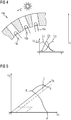
- FIG 4 shows a second embodiment of a beam detection unit 14a.
- This radiation detection unit 14a points to the optical waveguide 7 ( FIG 3 ) the discrete diodes as they are in FIG 3 are described on.
- the diodes can here also preferably be designed as photodiodes 15a, 15c.
- the beam detection unit 14a is below the optical waveguide 7 ( FIG 3 ), with an arrangement below that on the side of the optical waveguide 7 opposite the radiation incidence side ( FIG 3 ) is.
- the angle and orientation of the photodiodes 15a, 15c are identical to the angle of incidence range a1 and the angle of incidence range a2, that is to say those angles which generate critical reflection rays.
- the photodiodes 15a, 15c are operated in the reverse direction and allow a photocurrent and a photovoltage U1, U3 to increase almost linearly with increasing illuminance. Without incidence of light, the voltage U1 has a low value. This means that the voltage U1 and U3 depends on the position of the sun 4, which here moves along a path X in the course of the day. Thus, the voltage U1, U3 depends both on the position of the sun 4 along a path X and on the position of the optical waveguide 7 ( FIG 3 ) (tilted or not tilted, i.e. first or second position of the optical waveguide 7 ( FIG 3 )) from. As soon as light strikes the photodiode 15a or 15c directly, the voltage U1, U3 increases.
- the radiation detection unit 14a also has a third diode, preferably a third photodiode 15b. This is arranged centrally between the first diode 15a and the second diode 15c, and thus enables a redundant measurement in the minimum of the voltages. This means that the third photodiode 15b has a maximum in the voltage U2 in a solar ray incidence angle range, while the first photodiode 15a and the second photodiode 15c each have a minimum in this solar ray incidence angle range.
- FIG 5 shows such a safety-relevant safeguard in detail.
- U2 which is shown as the third dimension in the voltage diagram.
- an action and control area can be placed around the data, while a deviation from these ratios of the three voltages U1, U2, U3 represents a malfunction.
- the points A; B, C, D describe such a possible characteristic.
Landscapes
- Engineering & Computer Science (AREA)
- Chemical & Material Sciences (AREA)
- Combustion & Propulsion (AREA)
- Transportation (AREA)
- Mechanical Engineering (AREA)
- Physics & Mathematics (AREA)
- General Physics & Mathematics (AREA)
- Optics & Photonics (AREA)
- Photometry And Measurement Of Optical Pulse Characteristics (AREA)
Abstract
eine Bildgebungseinheit (8) zur optischen Übertragung und/oder Generierung von Bildinformationen, und
einen optischen Wellenleiter (7), welcher ausgebildet ist, die Bildinformationen in mindestens eine Richtung zu projizieren,
und eine gegenüber dem optischen Wellenleiter (7) geneigte Scheibe zur Reflexion der projizierten Bildinformationen des optischen Wellenleiters (7), so dass der Betrachter die Bildinformationen als ein virtuelles Bild in einem Anzeigebereich (9) an einer der benutzerabgewandten Seite der Scheibe wahrnimmt,
wobei
eine Strahlenerfassungseinheit (14, 14a) zur Erfassung eines Einfallswinkelbereiches (α1, α2) von auf den optischen Wellenleiter (7) einfallende Strahlung vorgesehen ist, und eine Steuereinheit (12) vorgesehen ist, welche mit der Strahlenerfassungseinheit (14, 14a) zur Datenübertragung verbunden ist, und welche ein Verkippen des optischen Wellenleiters (7) bei einem vorgegebenen Einfallswinkelbereichs bewerkstelligt.
Description
- Die Erfindung betrifft ein optisches System zur Erzeugung eines zwei- oder dreidimensionalen Bildes, umfassend eine Bildgebungseinheit zur optischen Übertragung und/oder Generierung von Bildinformationen und einen optischen Wellenleiter, welcher ausgebildet ist, die Bildinformationen in mindestens eine Richtung zu projizieren, ferner umfassend eine gegenüber dem optischen Wellenleiter geneigte Scheibe zur Reflexion der projizierten Bildinformationen des optischen Wellenleiters, so dass der Betrachter die Bildinformationen als ein virtuelles Bild in einem Anzeigebereich an einer der benutzerabgewandten Seite der Scheibe wahrnimmt.
- Durch ein Head-Up Display werden dem Fahrer eines Fahrzeuges relevante Informationen während der Fahrt angezeigt. Diese werden im Bereich der Windschutzscheibe in das Sichtfeld des Fahrers eingeblendet. Um die Sicht des Fahrers dabei möglichst wenig zu behindern, wird das eingeblendete Bild als virtuelles Bild vor der Windschutzscheibe dargestellt, so dass der Fahrer möglichst gleichzeitig die Umgebung und die eingeblendeten Daten beobachten kann, ohne das Auge unterschiedlich akkommodieren zu müssen.
- Nachteilig an diesem bekannten Head-Up-Display ist jedoch, dass auf die Windschutzscheibe von außen in Richtung des optischen Wellenleiters fallendes Störlicht von der reflektierten Oberfläche der Windschutzscheibe in eine Richtung gelenkt wird, in der sie über die Windschutzscheibe das Auge des Betrachters erreichen kann, und somit Irritationen beim Betrachter hervorruft.
- Die
WO 2019 038 201 A2 offenbart ein Head-Up-Display aufweisend ein Anzeigeelement, ein Projektionssystem, eine Streuscheibe und ein Spiegelelement, wobei die Streuscheibe auf ihrer dem Projektionssystem zugewandten Seite fokussierende Elemente aufweist, und auf ihrer dem Projektionssystem abgewandten Seite eine lichtblockierende Maske. - Es ist daher eine Aufgabe der Erfindung ein hinsichtlich Reflexionen verbessertes optisches System anzugeben.
- Diese Aufgabe wird durch ein optisches System mit den Merkmalen des Anspruchs 1 gelöst.
- In den Unteransprüchen sind weitere vorteilhafte Maßnahmen aufgelistet, die miteinander kombiniert werden können, um weitere Vorteile zu erzielen.
- Die Aufgabe wird gelöst durch ein optisches System zur Erzeugung eines zwei- oder dreidimensionalen Bildes, umfassend eine Bildgebungseinheit zur optischen Übertragung und/oder Generierung von Bildinformationen und einen optischen Wellenleiter, welcher ausgebildet ist, die Bildinformationen in mindestens eine Richtung zu projizieren und
ferner umfassend eine gegenüber dem optischen Wellenleiter geneigte Scheibe zur Reflexion der projizierten Bildinformationen des optischen Wellenleiters, so dass der Betrachter die Bildinformationen als ein virtuelles Bild in einem Anzeigebereich an einer der benutzerabgewandten Seite der Scheibe wahrnimmt, wobei eine Strahlenerfassungseinheit zur Erfassung eines Einfallswinkelbereiches von auf den optischen Wellenleiter einfallende Strahlung vorgesehen ist, und eine Steuereinheit vorgesehen ist, welche mit der Strahlenerfassungseinheit zur Datenübertragung verbunden ist, und welche ein Verkippen des optischen Wellenleiters bei einem vorgegebenen Einfallswinkelbereich bewerkstelligt. - Dabei kann ein optischer Wellenleiter beispielsweise eine holografische Wellenleiter-Einrichtung (Holographic-Waveguide) sein. Diese kann beispielsweise ein Einkopplungsgitter und ein Auskopplungsgitter und eine Platte aufweisen. Der optische Wellenleiter ist in der Lage, hochauflösende Vollfarbbilder, die unter Verwendung von Lichtquellen mit breiter Bandbreite und Wellenlänge erzeugt werden, durch ein optisch durchlässiges oder "durchsichtiges" Medium auf das Auge eines Betrachters zu projizieren.
Auch andere flache spekularen Reflektoren können mit optischer Wellenleiter umfasst sein. - Als Scheibe kann eine Streuscheibe, beispielsweise eine Windschutzscheibe ausgebildet sein.
- Einfallende Strahlung ist vorzugsweise Lichtstrahlung wie Sonneneinstrahlung/Sonnenlichtstrahlung.
- Es wurde erkannt, dass ein solcher optischer Wellenleiter jedoch eine Reihe von spezifischen Reflektionen bei Interaktion mit der Sonne aufweist. Die kritische Interaktion entsteht bei direkter Sonneneinstrahlung, bei der das Licht der Sonne über den optischen Wellenleiter und die Scheibe in ein Fahrerauge eines Fahrers reflektiert wird. Die Helligkeit dieses Reflexionsstrahls kann mehrere 10.000 cd/m2 betragen, und ist daher als sicherheitskritisch einzustufen.
- Erfindungsgemäß wurde erkannt, dass gängige Dämpfungsstrategien, die eine Reduktion des Reflexionsstrahles über eine Louverfolie, Polarisatoren, sowie spektrale Filter umfassen, das Nutzlicht überproportional dazu dämpfen würden. Ferner erzeugt eine Verwendung beispielsweise einer Folie wie einer Louverfolie einen hohen Herstellungsaufwand und ist mit hohen Kosten verbunden. Weiter wurde erkannt, dass eine Verwendung von Polarisatoren, oder spektralen Filtern ebenfalls mit hohen Kosten durch die benötigte Güte der Folien verbunden ist.
- Durch die Erfindung wird eine einfache Lösung zur Vermeidung von Reflexionsstrahlen, welche in das Fahrerauge fallen und dort für Irritationen sorgen, angegeben. Zur Messung der Sonneneinstrahlung wird eine Strahlenerfassungseinheit verwendet, welche zumindest datentechnisch mit der Steuereinheit verbunden ist.
- Zur Vermeidung des Sonnenreflexes wird im Falle des Erreichens eines kritischen Winkels, bei dem ein Reflexionsstrahl das Fahrerauge trifft, der optische Wellenleiter, auf den das Licht einfällt, verkippt. Durch die Verkippung werden von beispielsweise dem Sonnenlicht erzeugte Reflexionsstrahlen zuverlässig aus dem Bereich des Fahrerauges heraus bewegt, so dass diese nicht mehr das Fahrerauge treffen.
- Hier wurde erkannt, dass eine Verkippung möglich ist, da bei Verwendung eines optischen Wellenleiters eine Winkeltreue des eingekoppelten Lichtes vorliegt, so dass sich trotzt Bewegung des optischen Wellenleiters die Auskopplung nicht verändert.
- Vorzugsweise ist das optische System als Head-Up-Display in einem Fahrzeug ausgebildet.
- Vorzugsweise ist die Steuereinheit dazu ausgebildet, durch die Verkippung ein Ausfallwinkel der einfallenden Strahlung zu verändern. Durch den Ausfallwinkel kann der direkte Reflexionsstrahl, welcher ansonsten im Fahrerauge für Irritationen sorgt, verändert werden.
- Weiterhin vorzugsweise ist die Steuereinheit dazu ausgebildet, eine Verkippung entlang einer Vertikalachse des optischen Wellenleiters zu bewerkstelligen. Die direkte Sonneneinstrahlung wandert somit entlang der Vertikalachse. Dies hat den Vorteil, dass der Fahrer durch typische Seitwärtsbewegungen, wie sie oftmals bei Fahrern auftreten können, sich nicht in den reflektierten Reflexionsstrahl hineinbewegt.
- Weiterhin vorzugsweise ist die Steuereinheit dazu ausgebildet, den optischen Wellenleiter um einen Kippwinkel zwischen einer ersten Position und einer zweiten Position zu verkippen. Vorzugsweise liegen diese hinreichend weit auseinander, so dass ein unerwünschter Reflexionsstrahl das Fahrerauge in der jeweils anderen Position nicht erreicht. Durch das Vorhandensein von lediglich zwei Positionen kann ein schnelles Verkippen unterhalb von 500ms erzielt werden. Dies ist vorteilhaft, da beim Wechsel zwischen den Positionen der "Reflexzustand" zur Sonne durchfahren wird, das heißt, es kann ein direkter Reflexionsstrahl erzeugt werden, welcher in das Fahrerauge fällt. Dieser Zustand sollte so kurz wie möglich sein.
- Vorzugsweise beträgt der Kippwinkel 10 Grad oder weniger. Insbesondere vorteilhaft beträgt er um die 5 Grad. Diese Verkippung kann beispielsweise in einem Fahrzeug einfach bewerkstelligt werden.
- Vorzugsweise ist ein Aktorsystem vorgesehen, welches mit der Steuereinheit zumindest datentechnisch verbunden und mit dem optischen Wellenleiter verbunden ist. Somit kann die Steuereinheit mittels eines Signals an das Aktorsystem eine Verkippung des optischen Wellenleiters bewirken. Datentechnisch kann hier kabelgebunden oder drahtlos bedeuten. Vorzugsweise ist die Bildgebungseinheit derart ausgestaltet, dass diese zusammen mit dem optischen Wellenleiter verkippt wird. Dadurch ist ein besonders einfacher Aufbau des optischen Systems möglich.
- In weiterer bevorzugter Ausgestaltung ist die Strahlenerfassungseinheit an der der Strahlungseinfallseite gegenüberliegenden Seite des optischen Wellenleiters angeordnet. In anderen Worten heißt das, dass die Strahlenerfassungseinheit dabei unterhalb des optischen Wellenleiters angeordnet ist. Dadurch ist ein genaues Erfassen der Strahlung und insbesondere des Einfallswinkelbereiches der Strahlung, beispielsweise der Sonnenstrahlung, möglich.
- Vorzugsweise weist die Strahlenerfassungseinheit zumindest eine erste Diode und eine zweite Diode zur Messung eines ersten Einfallswinkelbereiches und eines zweiten Einfallswinkelbereiches eines auf den optischen Wellenleiters auftreffenden Lichtstrahls auf. Weiterhin vorzugsweise ist die erste Diode in einen zu dem ersten Einfallswinkelbereich im Wesentlichen identischen Winkel und die zweite Diode in einen zu dem zweiten Einfallswinkelbereich im Wesentlichen identischen Winkel in der Strahlenerfassungseinheit angeordnet. In weiterer bevorzugter Ausgestaltung ist die erste Diode derart in der Strahlenerfassungseinheit angeordnet, dass sie eine zu dem ersten Einfallswinkelbereich identische Orientierung aufweist und die zweite Diode derart in der Strahlenerfassungseinheit angeordnet, dass sie eine zu dem zweiten Einfallswinkelbereich identische Orientierung aufweist.
- Somit ist ein Messen des kritischen Winkels der Sonneneinstrahlung einfach möglich.
- Vorzugsweise ist die erste Diode als erste Photodiode und die zweite Diode als zweite Photodiode ausgebildet. Mittels einer Photodiode lässt sich eine Sonneneinstrahlung besonders einfach messen. Die Photodioden werden in Sperrrichtung betrieben und lassen einen Photostrom und eine Photospannung mit zunehmender Beleuchtungsstärke fast linear ansteigen.
- Anstatt Photodioden können auch Fototransistor oder Pyrheliometer, Photomultiplier zum Einsatz kommen.
- In weiterer bevorzugter Ausgestaltung weist die Strahlenerfassungseinheit eine dritte Diode auf, welche zwischen der ersten Diode und der zweiten Diode angeordnet ist. Diese kann ebenfalls als Photodiode ausgebildet sein. Weiterhin vorzugsweise ist die dritte Diode mittig zwischen der ersten Diode und der zweiten Diode angeordnet.
- Dadurch wird eine redundante Messung im Minimum der Spannungen, welche durch die erste und die zweite Diode bei direkter Sonneneinstrahlung entstehen, ermöglicht. Dies bedeutet, dass die dritte Photodiode bei einem gewissen Sonnenstrahleinfallswinkelbereich ein Maximum in der Spannung aufweist, während die erste Photodiode und die zweite Photodiode bei diesem Sonnenstrahleinfallswinkelbereich jeweils ein Minimum aufweisen. Dies kann als Safety-Relevante Absicherung bei der Ermittlung des Einfallswinkelbereiches der Sonnenstrahlung dienen, da die dritte Photodiode durch ihre Lage eine Kontrollgröße zu der ersten und zweiten Photodiode darstellt.
- Weitere Eigenschaften und Vorteile der vorliegenden Erfindung ergeben sich aus der nachfolgenden Beschreibung unter Bezugnahme auf die beiliegenden Figuren. Darin zeigen schematisch:
-
FIG 1 : ein ausgebildetes optisches System gemäß dem Stand der Technik, -
FIG 2 : ein erstes Ausführungsbeispiel eines erfindungsgemäßen optischen Systems, -
FIG 3 : das erfindungsgemäße optische System in einer verkippten Position, -
FIG 4 : eine weitere Ausgestaltung einer Strahlenerfassungseinheit mit Spannungsdiagramm, -
FIG 5 : die Funktion einer Safety-Relevanten Absicherung im Detail. -
FIG 1 zeigt ein als Head-Up-Display ausgebildetes optisches System 100 gemäß dem Stand der Technik. Dieses weist eine Bildgebungseinheit 8 auf. Ferner weist das optische System 100 einen optischen Wellenleiter 7, insbesondere einen holografischen Wellenreiter (holographic-Waveguide), auf. Das in der Bildgebungseinheit 8 (PGU) generierte Bild, wird über den optischen Wellenleiter 7 und eine Windschutzscheibe 3 in den Bereich des Fahrerauges 5 als Nutzlicht 6 reflektiert. - Das generierte Bild bzw. dessen Strahl wird dabei in den beispielsweise mehrschichtigen optischen Wellenleiter 7 eingekoppelt, innerhalb des optischen Wellenleiters 7 umgelenkt und zur Windschutzscheibe 3 hin ausgekoppelt, um über die Windschutzscheibe 3 reflektiert das virtuelle Bild in einem Anzeigebereich 9 auszubilden.
- Ein solcher optischer Wellenleiter 7 besteht aus einem optisch durchlässigen Material, das Licht mit den erforderlichen Wellenlängen ausbreitet. Das von der Bildgebungseinheit 8 ausgesendete Bild wird in dem optischen Wellenleiter 7 eingekoppelt. Dabei kann diese Einkopplung über einen Faltspiegel 2 erfolgen. Der optische Wellenleiter 7 ist in der Lage, hochauflösende Vollfarbbilder, die unter Verwendung von Lichtquellen mit breiter Bandbreite und Wellenlänge erzeugt werden, durch ein optisch durchlässiges oder "durchsichtiges" Medium auf das Fahrerauge 5 zu projizieren.
- Ein solcher optischer Wellenleiter 7 weist jedoch eine Reihe von spezifischen Reflektionen bei Interaktion mit der Sonne 4 auf. Die kritische Interaktion entsteht bei direkter Sonneneinstrahlung 10, bei der das Licht der Sonne über den optischen Wellenleiter 7 und die Windschutzscheibe 3 direkt in das Fahrerauge 5 des Fahrers reflektiert wird.
- Das direkte Sonnenlicht 10 fällt bei einem ersten Einfallswinkelbereich a1 auf den optischen Wellenleiter 7 und tritt unter einem ersten Ausfallwinkel β1 als erster direkter Reflexionsstrahl 11 aus.
- Die Helligkeit dieses ersten direkten Reflexionsstrahls 11 kann leicht mehrere 10.000 cd/m2 betragen, und ist daher als sicherheitskritisch einzustufen. Gängige Dämpfungsstrategien über eine Louverfolie, Polarisatoren sowie spektrale Filter würden zwar eine Reduktion der Reflexionsstrahlung erzielen, die zwar die Reflexionsstrahlung abschwächen jedoch das Nutzlicht 6 überproportional dämpfen.
-
FIG 2 zeigt ein optisches System 1 in einer ersten Ausgestaltung gemäß der Erfindung. - Dieses weist eine Bildgebungseinheit 8 zur Erzeugung von einem Bild für den Fahrer in dem Anzeigebereich 9 auf. Ferner weist das optische System optional einen Faltspiegel 2 auf. Auch weist das optische System 1 den optischen Wellenleiter 7 auf, welcher identisch mit dem in
FIG 1 sein kann. - Ferner weist das optische System 1 eine Windschutzscheibe 3 zur Reflexion des vom optischen Wellenleiter 7 erzeugten Bild auf.
- Ferner weist das optische System 1 eine Strahlenerfassungseinheit 14 (
FIG 3 ) zur Erfassung des ersten Einfallswinkelbereiches a1 (FIG 1 ) von auf den optischen Wellenleiter 7 einfallende direkte Sonneneinstrahlung 10 auf. - Ferner ist eine Steuereinheit 12 vorgesehen, welche mit der Strahlenerfassungseinheit 14 (
FIG 3 ) datentechnisch verbunden ist. Liegt der erfasste erste Einfallswinkelbereich a1 (FIG 1 ) und damit der Ausfallwinkel β1 in einem kritischen Bereich, so wird mittels der Steuereinheit 12 eine Verkippung des optischen Wellenleiters 7 von beispielsweise der ersten Position in die zweite Position bewirkt. - Die Verkippung kann durch ein Aktorsystem (nicht gezeigt) bewirkt werden. Weiterhin vorzugsweise ist eine Verkippung um eine Vertikalachse V vorgesehen, so dass die direkte Sonneneinstrahlung 10 unter einem zweiten Ausfallwinkel β2 reflektiert wird.
- Da der optische Wellenleiter 7 vertikal verkippt wird, wird die direkte Sonneneinstrahlung 10 unter dem zweiten Ausfallwinkel β2 reflektiert. Die direkte Sonneneinstrahlung 10 wandert bei einer solchen Verkippung entlang der Vertikalachse V. Dies hat den Vorteil, dass der Fahrer durch typische Seitwärtsbewegungen wie sie oftmals bei Fahrern auftreten können, sich nicht in den reflektierten zweiten direkten Reflexionsstrahl 13 hineinbewegt.
- Durch die Verkippung wird der erste direkte Reflexionsstrahl 11 zuverlässig aus dem Bereich des Fahrerauges 5 als zweiter direkter Reflexionsstrahl 13 heraus bewegt, so dass er nicht mehr das Fahrerauge 5 trifft.
- Vorzugsweise ist die Steuereinheit 12 dazu ausgebildet, den optischen Wellenleiter 7 um einen vorgegebenen Winkel von einer ersten Position in eine zweite Position, das heißt zwischen zwei dezidierten Zuständen, vertikal um einen Kippwinkel zu verkippen. Die Größe des Kippwinkels ist vorab eingestellt und abhängig von der eingestellten Bildhöhe und der Achse der Verkippung.
- Durch die Verkippung in lediglich zwei dezidierten Zuständen, das heißt zwischen zwei Positionen kann zudem eine schnelle Verkippung bewirkt werden. Zudem muss das Aktorsystem derart ausgebildet sein, dass es eine solche Verkippung zulässt. Eine solche Verkippung ist ausreichend, da die erste Position und die zweite Position hinreichend genug auseinanderliegen, so dass der direkte erste Reflexionsstrahl 11 in den zweiten Reflexionsstrahl 13 umgewandelt wird, bei dem der zweite Reflexionsstrahl 13 nicht mehr zum Fahrerauge 5 gelangt.
- Durch das erfindungsgemäße optische System 1 mit lediglich zwei dezidierten Zuständen kann zwischen den Positionen unterhalb von 500 ms gewechselt werden. Der Grund für die Geschwindigkeit des Wechsels liegt vor allem in der nicht auszuschließenden Möglichkeit, dass beim Wechsel der "Reflexzustand" zur Sonne 4 durchfahren wird. Daher muss ein Wechsel schnell erfolgen.
- Zusätzlich können die Positionen in einer 2-dimensionalen Bewegung durchfahren werden. Hierbei würde die zweite Dimension einer Kippung um die Horizontalachse (nicht gezeigt) entsprechen. Bei dieser Bewegung würde die Horizontalachse zum Ausweichen des Sonnenreflexes beim Übergang ausgesteuert werden. Die Horizontalachse ist dabei orthogonal zur Vertikalachse V.
- Vorzugsweise beträgt ein solcher Kippwinkel bis zu 10 Grad, insbesondere ca. 5 Grad. Eine solche Verkippung kann problemlos ermöglicht werden.
- Mehrere solcher Kippwinkel können beispielsweise in einer nicht gezeigten Speichereinheit in Abhängigkeit von der Bildhöhe gespeichert sein und von der Steuereinheit 12 auslesbar sein.
- Durch das erfindungsgemäße optische System 1 ist eine Reflexionsvermeidung anhand einer geometrischen Entspiegelung durch Verkippung des optischen Wellenleiters 7 in kritischen Reflexionssituationen möglich. Die Möglichkeit eine solche Verkippung eines optischen Wellenleiters 7 anzuwenden liegt unter anderem in der Winkeltreue des eingekoppelten Lichtes, so dass sich trotzt Bewegung des optischen Wellenleiters 7 die Auskopplung nicht verändert. Weiterhin vorzugsweise können der Faltspiegel 2 und die Bildgebungseinheit 8 mit dem optischen Wellenleiter 7 verkippt werden.
- Wird bei Wanderung der Sonne 4 und damit der Sonneneinstrahlung 10 der zweite Reflexionsstrahl 13 zum kritischen Reflexionsstrahl mit zweiten Einfallswinkelbereich a2, so wird eine (Rück)Verkippung des optischen Wellenleiters 7 von beispielsweise der zweiten Position in die erste Position bewirkt.
- In anderen Worten: Liegt der Ausfallwinkel β2 in einem kritischen Bereich, so wird mittels der Steuereinheit 12 eine Verkippung des optischen Wellenleiters 7 beispielsweise der zweiten Position in die erste Position bewirkt.
- Im Falle einer Verzerrung des entstehenden virtuellen Bildes beispielsweise aufgrund von Fehlern in der Windschutzscheibe 3 ist ein Ausgleich/ Kompensation über eine Software oder ein weiteres optisches Element notwendig.
-
FIG 3 zeigt das erfindungsgemäße optische System 1 in einer verkippten Position. Das optische System 1 weist die Strahlenerfassungseinheit 14 zur Erfassung des ersten Einfallswinkelbereiches a1 (FIG 1 ) von auf den optischen Wellenleiter 7 einfallende direkte Sonneneinstrahlung 10 auf. - Die Strahlenerfassungseinheit 14 weist zur Detektion des Sonnenstandes bzw. des Einfallswinkelbereiches a1 zumindest zwei diskrete Dioden auf. Die Dioden sind hier vorzugsweise als Photodioden 15a, 15c ausgebildet. Die Strahlenerfassungseinheit 14 ist dabei unterhalb des optischen Wellenleiters 7 angeordnet, wobei unterhalb eine Anordnung an der der Strahlungseinfallseite gegenüberliegenden Seite des optischen Wellenleiters 7 ist.
- Die Photodioden 15a,15c sind in Winkel und Orientierung identisch zu dem Einfallswinkelbereich a1 und dem Einfallswinkelbereich a2, das heißt denjenigen Winkeln, welche kritische Reflexionsstrahlen erzeugen, angeordnet.
- Die Photodioden 15a,15c werden in Sperrrichtung betrieben und lassen einen Fotostrom mit zunehmender Beleuchtungsstärke fast linear ansteigen. Ohne Lichteinfall weist der Fotostrom, bei dem es sich um einen Sperrstrom handelt, ähnliche geringe Werte wie bei anderen Siliziumdioden auf. Sobald Licht in die Sperrschicht fällt, werden durch die Lichtteilchen zusätzliche Elektronen aus dem Kristallgitter herausgeschlagen. Dadurch steigt der Fotostrom mit zunehmender Beleuchtungsstärke an. Der Zusammenhang zwischen Fotostrom und Beleuchtungsstärke ist nahezu linear.
- Das heißt, ohne Lichteinfall verhält sich eine Photodiode wie eine herkömmliche Diode. Durch den Lichteinfall werden in der Sperrschicht zusätzliche Elektronen frei und der Fotostrom steigt an.
- Anstatt Photodioden können auch Fototransistor verwendet werden oder Pyrheliometer, Photomultiplier.
- Steigt der Fotostrom, das heißt die Photospannung an, so bewirkt dies eine Verkippung des optischen Wellenleiters 7. Dabei bedeutet ein Anstieg, dass der Einfallswinkelbereich a1 oder α2 und damit ein kritischer erster Reflexionsstrahl 12 oder ein kritischer zweiter Reflexionsstrahl 13 vorliegt.
- Ferner ist eine Steuereinheit 12 vorgesehen, welche mit der Strahlenerfassungseinheit 14 datentechnisch verbunden ist. Liegt der erfasste Einfallswinkelbereich a1 (
FIG 1 ) und damit der Ausfallwinkel β1 in einem kritischen Bereich so wird mittels der Steuereinheit 12 eine Verkippung des optischen Wellenleiters 7 von beispielsweise der ersten Position in die zweite Position bewirkt. - Wird bei Wanderung der Sonne 4 und damit der Sonneneinstrahlung 10 der zweite Reflexionsstrahl 13 mit kritischen zweiten Einfallswinkelbereich α2 zum kritischen Reflexionsstrahl, so wird eine (Rück)Verkippung des optischen Wellenleiters 7 von beispielsweise der zweiten Position in die erste Position bewirkt.
- Dabei kann ein Aktorsystem (nicht gezeigt) vorgesehen sein. Weiterhin vorzugsweise ist eine Verkippung um eine Vertikalachse V vorgesehen, so dass die direkte Sonneneinstrahlung 10 unter einem zweiten Ausfallwinkel β2 reflektiert wird.
-
FIG 4 zeigt eine zweite Ausgestaltung einer Strahlenerfassungseinheit 14a. - Diese Strahlenerfassungseinheit 14a weist zur Detektion des Sonnenstandes bzw. des Einfallswinkelbereiches α1, α2 auf den optischen Wellenleiter 7 (
FIG 3 ) die diskreten Dioden, wie sie inFIG 3 beschrieben sind, auf. Die Dioden können hier ebenfalls vorzugsweise als Photodioden 15a, 15c ausgebildet sein. Die Strahlenerfassungseinheit 14a ist dabei unterhalb des optischen Wellenleiters 7 (FIG 3 ) angeordnet, wobei unterhalb, eine Anordnung an der der Strahlungseinfallseite gegenüberliegenden Seite des optischen Wellenleiters 7 (FIG 3 ) ist. - Die Photodioden 15a,15c sind in Winkel und Orientierung identisch zu dem Einfallswinkelbereich a1 und dem Einfallswinkelbereich a2, das heißt denjenigen Winkeln, welche kritische Reflexionsstrahlen erzeugen, angeordnet.
- Die Photodioden 15a,15c werden in Sperrrichtung betrieben und lassen einen Photostrom und eine Photospannung U1, U3 mit zunehmender Beleuchtungsstärke fast linear ansteigen. Ohne Lichteinfall weist die Spannung U1 einen geringen Wert auf. Das heißt die Spannung U1 und U3 hängt vom Stand der Sonne 4 ab, welche sich hier im Laufe des Tages entlang eines Weges X bewegt. Somit hängt die Spannung U1, U3 sowohl von der Position der Sonne 4 entlang eines Weges X ab als auch von der Position des optischen Wellenleiters 7 (
FIG 3 ) (verkippt oder nicht verkippt, das heißt erste oder zweite Position des optischen Wellenleiters 7 (FIG 3 )) ab. Sobald Licht auf die Photodiode 15a oder 15c direkt einfällt, steigt die Spannung U1, U3 an. - Ferner weist die Strahlenerfassungseinheit 14a noch eine dritte Diode, vorzugsweise eine dritte Photodiode 15b auf. Diese ist mittig zwischen der ersten Diode 15a und der zweiten Diode 15c angeordnet, und ermöglicht so eine redundante Messung im Minimum der Spannungen. Dies bedeutet, dass die dritte Photodiode 15b ein Maximum in der Spannung U2 bei einem Sonnenstrahleinfallswinkelbereich aufweist, während die erste Photodiode 15a und die zweite Photodiode 15c bei diesem Sonnenstrahleinfallswinkelbereich jeweils ein Minimum aufweisen. Dies kann als Safety-Relevante Absicherung bei der Ermittlung des Einfallswinkelbereiches der Sonnenstrahlung genutzt werden, indem die dritte Photodiode 15b durch ihre Lage eine Kontrollgröße zu der ersten Photodiode 15a und zu der zweiten Photodiode 15c darstellt.
-
FIG 5 zeigt eine solche Safety-Relevante Absicherung im Detail. Mit Ausnahme der Extremlagen existiert durch die Kontrollgröße U2 ein Übergangsbereich, der sich im Spannungsdiagramm als dritte Dimension darstellt. Mit Hilfe eines "Tunnels" um eine Kennlinie lässt sich damit ein Aktions- und Steuerungsbereich um die Daten legen, während eine Abweichung um diese Verhältnisse der drei Spannungen U1, U2, U3 eine Fehlfunktion darstellen. Die Punkte A; B, C, D beschreiben eine solche mögliche Kennlinie.
Claims (15)
- Optisches System (1) zur Erzeugung eines zwei- oder dreidimensionalen Bildes, umfassend
eine Bildgebungseinheit (8) zur optischen Übertragung und/oder Generierung von Bildinformationen, und
einen optischen Wellenleiter (7), welcher ausgebildet ist, die Bildinformationen in mindestens eine Richtung zu projizieren,
und eine gegenüber dem optischen Wellenleiter (7) geneigte Scheibe zur Reflexion der projizierten Bildinformationen des optischen Wellenleiters (7), so dass der Betrachter die Bildinformationen als ein virtuelles Bild in einem Anzeigebereich (9) an einer der benutzerabgewandten Seite der Scheibe wahrnimmt,
dadurch gekennzeichnet, dass
eine Strahlenerfassungseinheit (14, 14a) zur Erfassung eines Einfallswinkelbereiches (α1, α2) von auf den optischen Wellenleiter (7) einfallende Strahlung vorgesehen ist, und eine Steuereinheit (12) vorgesehen ist, welche mit der Strahlenerfassungseinheit (14, 14a) zur Datenübertragung verbunden ist, und welche ein Verkippen des optischen Wellenleiters (7) bei einem vorgegebenen Einfallswinkelbereichs bewerkstelligt. - Optisches System (1) nach Anspruch 1, dadurch gekennzeichnet, d ass
die Steuereinheit (12) dazu ausgebildet ist, durch die Verkippung ein Ausfallwinkel (β1, β2) der einfallenden Strahlung zu verändern. - Optisches System (1) nach Anspruch 1 oder 2, dadurch gekennzeich net, dass
die Steuereinheit (12) dazu ausgebildet ist, eine Verkippung entlang einer Vertikalachse (V) des optischen Wellenleiters (7) zu bewerkstelligen. - Optisches System (1) nach einem der vorhergehenden Ansprüche, dadurch gekennzeichnet, dass
die Steuereinheit (12) dazu ausgebildet ist, den optischen Wellenleiter (7) um einen Kippwinkel zwischen einer ersten Position und einer zweiten Position zu verkippen. - Optisches System (1) nach Anspruch 4, dadurch gekennzeichnet, d ass
der Kippwinkel 10 Grad oder weniger beträgt. - Optisches System (1) nach einem der vorhergehenden Ansprüche, dadurch gekennzeichnet, dass
ein Aktorsystem vorgesehen ist, welches mit der Steuereinheit (12) zumindest datentechnisch verbunden ist und mit dem optischen Wellenleiter (7) verbunden ist. - Optisches System (1) nach Anspruch 6, dadurch gekennzeichnet, d ass
die Bildgebungseinheit (8) derart ausgestaltet ist, dass diese zusammen mit dem optischen Wellenleiter (7) verkippt wird. - Optisches System (1) nach einem der vorhergehenden Ansprüche, dadurch gekennzeichnet, dass
die Strahlenerfassungseinheit (14,14a) an der der Strahlungseinfallseite gegenüberliegenden Seite des optischen Wellenleiters (7) angeordnet ist. - Optisches System (1) nach einem der vorhergehenden Ansprüche, dadurch gekennzeichnet, dass
die Strahlenerfassungseinheit (14,14a) zumindest eine erste Diode und eine zweite Diode zur Messung eines ersten Einfallswinkelbereiches (a1) und eines zweiten Einfallswinkelbereiches (a2) eines auf den optischen Wellenleiters (7) auftreffenden Lichtstrahls aufweist. - Optisches System (1) nach Anspruch 9, dadurch gekennzeichnet, d ass
die erste Diode in einen zu dem ersten Einfallswinkelbereich (a1) im Wesentlichen identischen Winkel und die zweite Diode in einen zu dem zweiten Einfallswinkelbereich (α2) im Wesentlichen identischen Winkel in der Strahlenerfassungseinheit (14, 14a) angeordnet ist. - Optisches System (1) nach Anspruch 9 oder 10, dadurch gekennzeic hnet, dass
die erste Diode derart in der Strahlenerfassungseinheit (14, 14a) angeordnet ist, dass sie eine zu dem ersten Einfallswinkelbereich (a1) identische Orientierung aufweist und die zweite Diode derart in der Strahlenerfassungseinheit (14, 14a) angeordnet ist, dass sie eine zu dem zweiten Einfallswinkelbereich (a2) identische Orientierung aufweist. - Optisches System (1) nach einem der vorhergehenden Ansprüche 9 bis 11, d a durch gekennzeichnet, dass
die erste Diode als erste Photodiode (15a) und die zweite Diode als zweite Photodiode (15c) ausgebildet ist. - Optisches System (1) nach einem der vorhergehenden Ansprüche 9 bis 12, d a durch gekennzeichnet, dass
die Strahlenerfassungseinheit (14,14a) eine dritte Diode aufweist, welche zwischen der ersten Diode und der zweiten Diode angeordnet ist. - Optisches System (1) nach Anspruch 13, dadurch gekennzeichnet, dass
die dritte Diode mittig zwischen der ersten Diode und der zweiten Diode angeordnet ist. - Optisches System (1) nach einem der vorhergehenden Ansprüche, dadurch gekennzeichnet, dass
das optische System (1) als ein Head-Up-Display ausgestaltet ist.
Applications Claiming Priority (1)
| Application Number | Priority Date | Filing Date | Title |
|---|---|---|---|
| DE102019219518.0A DE102019219518A1 (de) | 2019-12-13 | 2019-12-13 | Optisches System zur Erzeugung eines zwei- oder dreidimensionalen Bildes |
Publications (2)
| Publication Number | Publication Date |
|---|---|
| EP3835849A1 true EP3835849A1 (de) | 2021-06-16 |
| EP3835849B1 EP3835849B1 (de) | 2025-09-24 |
Family
ID=73401322
Family Applications (1)
| Application Number | Title | Priority Date | Filing Date |
|---|---|---|---|
| EP20207066.0A Active EP3835849B1 (de) | 2019-12-13 | 2020-11-12 | Optisches system zur erzeugung eines zwei- oder dreidimensionalen bildes |
Country Status (2)
| Country | Link |
|---|---|
| EP (1) | EP3835849B1 (de) |
| DE (1) | DE102019219518A1 (de) |
Citations (5)
| Publication number | Priority date | Publication date | Assignee | Title |
|---|---|---|---|---|
| JP2007148092A (ja) * | 2005-11-29 | 2007-06-14 | Denso Corp | ヘッドアップディスプレイ装置 |
| WO2019038201A2 (de) | 2017-08-22 | 2019-02-28 | Continental Automotive Gmbh | Head-up-display |
| DE102017216524A1 (de) * | 2017-09-19 | 2019-03-21 | Bayerische Motoren Werke Aktiengesellschaft | Head-up-Anzeigevorrichtung für ein Kraftfahrzeug |
| US20190212557A1 (en) * | 2018-01-08 | 2019-07-11 | Digilens, Inc. | Waveguide Architectures and Related Methods of Manufacturing |
| DE102019205138A1 (de) * | 2018-04-13 | 2019-10-17 | Denso Corporation | HEAD-UP-Anzeigevorrichtung |
Family Cites Families (1)
| Publication number | Priority date | Publication date | Assignee | Title |
|---|---|---|---|---|
| CN207752235U (zh) * | 2017-11-22 | 2018-08-21 | 苏州车萝卜汽车电子科技有限公司 | 风挡式抬头显示装置 |
-
2019
- 2019-12-13 DE DE102019219518.0A patent/DE102019219518A1/de active Pending
-
2020
- 2020-11-12 EP EP20207066.0A patent/EP3835849B1/de active Active
Patent Citations (5)
| Publication number | Priority date | Publication date | Assignee | Title |
|---|---|---|---|---|
| JP2007148092A (ja) * | 2005-11-29 | 2007-06-14 | Denso Corp | ヘッドアップディスプレイ装置 |
| WO2019038201A2 (de) | 2017-08-22 | 2019-02-28 | Continental Automotive Gmbh | Head-up-display |
| DE102017216524A1 (de) * | 2017-09-19 | 2019-03-21 | Bayerische Motoren Werke Aktiengesellschaft | Head-up-Anzeigevorrichtung für ein Kraftfahrzeug |
| US20190212557A1 (en) * | 2018-01-08 | 2019-07-11 | Digilens, Inc. | Waveguide Architectures and Related Methods of Manufacturing |
| DE102019205138A1 (de) * | 2018-04-13 | 2019-10-17 | Denso Corporation | HEAD-UP-Anzeigevorrichtung |
Non-Patent Citations (1)
| Title |
|---|
| SALGADO-CONRADO LIZBETH: "A review on sun position sensors used in solar applications", RENEWABLE AND SUSTAINABLE ENERGY REVIEWS, vol. 82, 11 October 2017 (2017-10-11), pages 2128 - 2146, XP085314672, ISSN: 1364-0321, DOI: 10.1016/J.RSER.2017.08.040 * |
Also Published As
| Publication number | Publication date |
|---|---|
| DE102019219518A1 (de) | 2021-06-17 |
| EP3835849B1 (de) | 2025-09-24 |
Similar Documents
| Publication | Publication Date | Title |
|---|---|---|
| EP3688511B1 (de) | Anzeigevorrichtung, insbesondere für ein fahrzeug, sowie fahrzeug mit einer solchen anzeigevorrichtung | |
| EP3673317B1 (de) | Head-up-display | |
| EP4214566B1 (de) | Gerät zum generieren eines virtuellen bildes mit einem verstellmechanismus für entspiegelungslamellen | |
| DE2729212A1 (de) | Sichtvorrichtung | |
| DE4104233A1 (de) | Kraftfahrzeug-anzeigevorrichtung vom reflexionstyp | |
| WO2017084894A1 (de) | Abdeckelement zum abdecken einer projektionsöffnung eines head-up-displays, head-up-display und verfahren zum leiten von licht durch ein abdeckelement | |
| DE3100473A1 (de) | Anzeigeeinrichtung fuer informationsmarkierungen | |
| EP4022883A1 (de) | Kameravorrichtung zum erzeugen eines abbilds einer umgebung | |
| DE102016202464A1 (de) | Projektionsvorrichtung für ein Head-Up-Display, Head-Up-Display sowie Fahrzeug | |
| DE102013210887A1 (de) | Optische Sensoranordnung für ein Fahrzeug und Fahrzeug mit einer derartigen Sensoranordnung | |
| WO2012098192A1 (de) | Kameraanordnung für ein kraftfahrzeug | |
| DE102018200626A1 (de) | Detektionsvorrichtung zur Detektion von Verschmutzungen | |
| EP3807705A1 (de) | Head-up-display für ein fahrzeug | |
| DE102014110606A1 (de) | Mikroskop mit einer Strahlteileranordnung | |
| DE2651720C3 (de) | Optisches Suchersystem für eine Spiegelreflexkamera | |
| EP3835849B1 (de) | Optisches system zur erzeugung eines zwei- oder dreidimensionalen bildes | |
| DE102013100292A1 (de) | Beleuchtung zur Detektion von Regentropfen auf einer Scheibe mittels einer Kamera | |
| DE102017202018B4 (de) | Scannersystem mit einer Strahlquelle, einem Spiegel und einem prismatischen Element | |
| DE102008011761A1 (de) | Justagevorrichtung für eine Mikrolithografie-Projektionsbelichtungsanlage, Beleuchtungssystem mit einer derartigen Justagevorrichtung sowie Projektionsbelichtungsanlage mit einem derartigen Beleuchtungssystem | |
| DE202022102679U1 (de) | Optisches System für Periskopkameramodul | |
| DE102025108270B3 (de) | Höhenerweiterung eines für virtuelle Anzeige im Schwarzdruck nutzbaren Bereichs eines Scheibenwurzeldisplays in einem Fahrzeug sowie Fahrzeug | |
| DE102019206378A1 (de) | Abstandsmesssystem | |
| DE2952207A1 (de) | Prismensucher fuer spiegelreflexkameras mit belichtungsmesser | |
| WO2024208725A1 (de) | Optische anordnung für head-up display und winkelselektive filteranordnung mit mikrolamellengitter | |
| DE102023110525A1 (de) | Optische anordnung für head-up display und winkelselektive filteranordnung mit mikrolamellengitter |
Legal Events
| Date | Code | Title | Description |
|---|---|---|---|
| PUAI | Public reference made under article 153(3) epc to a published international application that has entered the european phase |
Free format text: ORIGINAL CODE: 0009012 |
|
| STAA | Information on the status of an ep patent application or granted ep patent |
Free format text: STATUS: THE APPLICATION HAS BEEN PUBLISHED |
|
| AK | Designated contracting states |
Kind code of ref document: A1 Designated state(s): AL AT BE BG CH CY CZ DE DK EE ES FI FR GB GR HR HU IE IS IT LI LT LU LV MC MK MT NL NO PL PT RO RS SE SI SK SM TR |
|
| STAA | Information on the status of an ep patent application or granted ep patent |
Free format text: STATUS: REQUEST FOR EXAMINATION WAS MADE |
|
| 17P | Request for examination filed |
Effective date: 20211216 |
|
| RBV | Designated contracting states (corrected) |
Designated state(s): AL AT BE BG CH CY CZ DE DK EE ES FI FR GB GR HR HU IE IS IT LI LT LU LV MC MK MT NL NO PL PT RO RS SE SI SK SM TR |
|
| RAP1 | Party data changed (applicant data changed or rights of an application transferred) |
Owner name: CONTINENTAL AUTOMOTIVE TECHNOLOGIES GMBH |
|
| STAA | Information on the status of an ep patent application or granted ep patent |
Free format text: STATUS: EXAMINATION IS IN PROGRESS |
|
| 17Q | First examination report despatched |
Effective date: 20230808 |
|
| RAP3 | Party data changed (applicant data changed or rights of an application transferred) |
Owner name: CONTINENTAL AUTOMOTIVE TECHNOLOGIES GMBH |
|
| GRAP | Despatch of communication of intention to grant a patent |
Free format text: ORIGINAL CODE: EPIDOSNIGR1 |
|
| STAA | Information on the status of an ep patent application or granted ep patent |
Free format text: STATUS: GRANT OF PATENT IS INTENDED |
|
| RIC1 | Information provided on ipc code assigned before grant |
Ipc: B60K 35/23 20240101ALI20250430BHEP Ipc: B60K 35/80 20240101ALI20250430BHEP Ipc: B60K 35/40 20240101ALI20250430BHEP Ipc: B60K 35/28 20240101ALI20250430BHEP Ipc: G02B 27/00 20060101ALI20250430BHEP Ipc: B60R 1/00 20060101ALI20250430BHEP Ipc: B60K 35/00 20060101ALI20250430BHEP Ipc: G02B 27/01 20060101AFI20250430BHEP |
|
| INTG | Intention to grant announced |
Effective date: 20250515 |
|
| GRAS | Grant fee paid |
Free format text: ORIGINAL CODE: EPIDOSNIGR3 |
|
| GRAA | (expected) grant |
Free format text: ORIGINAL CODE: 0009210 |
|
| STAA | Information on the status of an ep patent application or granted ep patent |
Free format text: STATUS: THE PATENT HAS BEEN GRANTED |
|
| AK | Designated contracting states |
Kind code of ref document: B1 Designated state(s): AL AT BE BG CH CY CZ DE DK EE ES FI FR GB GR HR HU IE IS IT LI LT LU LV MC MK MT NL NO PL PT RO RS SE SI SK SM TR |
|
| REG | Reference to a national code |
Ref country code: GB Ref legal event code: FG4D Free format text: NOT ENGLISH |
|
| REG | Reference to a national code |
Ref country code: CH Ref legal event code: EP |
|
| REG | Reference to a national code |
Ref country code: DE Ref legal event code: R096 Ref document number: 502020011967 Country of ref document: DE |
|
| REG | Reference to a national code |
Ref country code: CH Ref legal event code: W10 Free format text: ST27 STATUS EVENT CODE: U-0-0-W10-W00 (AS PROVIDED BY THE NATIONAL OFFICE) Effective date: 20251022 Ref country code: IE Ref legal event code: FG4D Free format text: LANGUAGE OF EP DOCUMENT: GERMAN |
|
| RAP4 | Party data changed (patent owner data changed or rights of a patent transferred) |
Owner name: AUMOVIO GERMANY GMBH |
|
| PGFP | Annual fee paid to national office [announced via postgrant information from national office to epo] |
Ref country code: DE Payment date: 20251130 Year of fee payment: 6 |
|
| PG25 | Lapsed in a contracting state [announced via postgrant information from national office to epo] |
Ref country code: NO Free format text: LAPSE BECAUSE OF FAILURE TO SUBMIT A TRANSLATION OF THE DESCRIPTION OR TO PAY THE FEE WITHIN THE PRESCRIBED TIME-LIMIT Effective date: 20251224 |
|
| REG | Reference to a national code |
Ref country code: LT Ref legal event code: MG9D |
|
| PG25 | Lapsed in a contracting state [announced via postgrant information from national office to epo] |
Ref country code: FI Free format text: LAPSE BECAUSE OF FAILURE TO SUBMIT A TRANSLATION OF THE DESCRIPTION OR TO PAY THE FEE WITHIN THE PRESCRIBED TIME-LIMIT Effective date: 20250924 |
|
| PG25 | Lapsed in a contracting state [announced via postgrant information from national office to epo] |
Ref country code: HR Free format text: LAPSE BECAUSE OF FAILURE TO SUBMIT A TRANSLATION OF THE DESCRIPTION OR TO PAY THE FEE WITHIN THE PRESCRIBED TIME-LIMIT Effective date: 20250924 |
|
| PGFP | Annual fee paid to national office [announced via postgrant information from national office to epo] |
Ref country code: FR Payment date: 20251124 Year of fee payment: 6 |
|
| PG25 | Lapsed in a contracting state [announced via postgrant information from national office to epo] |
Ref country code: GR Free format text: LAPSE BECAUSE OF FAILURE TO SUBMIT A TRANSLATION OF THE DESCRIPTION OR TO PAY THE FEE WITHIN THE PRESCRIBED TIME-LIMIT Effective date: 20251225 |
|
| PG25 | Lapsed in a contracting state [announced via postgrant information from national office to epo] |
Ref country code: SE Free format text: LAPSE BECAUSE OF FAILURE TO SUBMIT A TRANSLATION OF THE DESCRIPTION OR TO PAY THE FEE WITHIN THE PRESCRIBED TIME-LIMIT Effective date: 20250924 |
|
| PG25 | Lapsed in a contracting state [announced via postgrant information from national office to epo] |
Ref country code: LV Free format text: LAPSE BECAUSE OF FAILURE TO SUBMIT A TRANSLATION OF THE DESCRIPTION OR TO PAY THE FEE WITHIN THE PRESCRIBED TIME-LIMIT Effective date: 20250924 |
|
| PG25 | Lapsed in a contracting state [announced via postgrant information from national office to epo] |
Ref country code: BG Free format text: LAPSE BECAUSE OF FAILURE TO SUBMIT A TRANSLATION OF THE DESCRIPTION OR TO PAY THE FEE WITHIN THE PRESCRIBED TIME-LIMIT Effective date: 20250924 |
|
| REG | Reference to a national code |
Ref country code: DE Ref legal event code: R081 Ref document number: 502020011967 Country of ref document: DE Owner name: AUMOVIO GERMANY GMBH, DE Free format text: FORMER OWNER: CONTINENTAL AUTOMOTIVE TECHNOLOGIES GMBH, 30175 HANNOVER, DE |
|
| PGFP | Annual fee paid to national office [announced via postgrant information from national office to epo] |
Ref country code: RO Payment date: 20251028 Year of fee payment: 6 |
|
| PG25 | Lapsed in a contracting state [announced via postgrant information from national office to epo] |
Ref country code: RS Free format text: LAPSE BECAUSE OF FAILURE TO SUBMIT A TRANSLATION OF THE DESCRIPTION OR TO PAY THE FEE WITHIN THE PRESCRIBED TIME-LIMIT Effective date: 20251224 |
|
| REG | Reference to a national code |
Ref country code: NL Ref legal event code: MP Effective date: 20250924 |
|
| PG25 | Lapsed in a contracting state [announced via postgrant information from national office to epo] |
Ref country code: NL Free format text: LAPSE BECAUSE OF FAILURE TO SUBMIT A TRANSLATION OF THE DESCRIPTION OR TO PAY THE FEE WITHIN THE PRESCRIBED TIME-LIMIT Effective date: 20250924 |
|
| PG25 | Lapsed in a contracting state [announced via postgrant information from national office to epo] |
Ref country code: SM Free format text: LAPSE BECAUSE OF FAILURE TO SUBMIT A TRANSLATION OF THE DESCRIPTION OR TO PAY THE FEE WITHIN THE PRESCRIBED TIME-LIMIT Effective date: 20250924 |
|
| PG25 | Lapsed in a contracting state [announced via postgrant information from national office to epo] |
Ref country code: ES Free format text: LAPSE BECAUSE OF FAILURE TO SUBMIT A TRANSLATION OF THE DESCRIPTION OR TO PAY THE FEE WITHIN THE PRESCRIBED TIME-LIMIT Effective date: 20250924 |
|
| PG25 | Lapsed in a contracting state [announced via postgrant information from national office to epo] |
Ref country code: IT Free format text: LAPSE BECAUSE OF FAILURE TO SUBMIT A TRANSLATION OF THE DESCRIPTION OR TO PAY THE FEE WITHIN THE PRESCRIBED TIME-LIMIT Effective date: 20250924 |
|
| PG25 | Lapsed in a contracting state [announced via postgrant information from national office to epo] |
Ref country code: IS Free format text: LAPSE BECAUSE OF FAILURE TO SUBMIT A TRANSLATION OF THE DESCRIPTION OR TO PAY THE FEE WITHIN THE PRESCRIBED TIME-LIMIT Effective date: 20260124 |
|
| PG25 | Lapsed in a contracting state [announced via postgrant information from national office to epo] |
Ref country code: CZ Free format text: LAPSE BECAUSE OF FAILURE TO SUBMIT A TRANSLATION OF THE DESCRIPTION OR TO PAY THE FEE WITHIN THE PRESCRIBED TIME-LIMIT Effective date: 20250924 Ref country code: PT Free format text: LAPSE BECAUSE OF FAILURE TO SUBMIT A TRANSLATION OF THE DESCRIPTION OR TO PAY THE FEE WITHIN THE PRESCRIBED TIME-LIMIT Effective date: 20260126 |
|
| PG25 | Lapsed in a contracting state [announced via postgrant information from national office to epo] |
Ref country code: PL Free format text: LAPSE BECAUSE OF FAILURE TO SUBMIT A TRANSLATION OF THE DESCRIPTION OR TO PAY THE FEE WITHIN THE PRESCRIBED TIME-LIMIT Effective date: 20250924 |
|
| PG25 | Lapsed in a contracting state [announced via postgrant information from national office to epo] |
Ref country code: EE Free format text: LAPSE BECAUSE OF FAILURE TO SUBMIT A TRANSLATION OF THE DESCRIPTION OR TO PAY THE FEE WITHIN THE PRESCRIBED TIME-LIMIT Effective date: 20250924 Ref country code: SK Free format text: LAPSE BECAUSE OF FAILURE TO SUBMIT A TRANSLATION OF THE DESCRIPTION OR TO PAY THE FEE WITHIN THE PRESCRIBED TIME-LIMIT Effective date: 20250924 |
|
| REG | Reference to a national code |
Ref country code: CH Ref legal event code: H13 Free format text: ST27 STATUS EVENT CODE: U-0-0-H10-H13 (AS PROVIDED BY THE NATIONAL OFFICE) Effective date: 20260623 |
|
| REG | Reference to a national code |
Ref country code: DE Ref legal event code: R097 Ref document number: 502020011967 Country of ref document: DE |
|
| PG25 | Lapsed in a contracting state [announced via postgrant information from national office to epo] |
Ref country code: LT Free format text: LAPSE BECAUSE OF FAILURE TO SUBMIT A TRANSLATION OF THE DESCRIPTION OR TO PAY THE FEE WITHIN THE PRESCRIBED TIME-LIMIT Effective date: 20250924 Ref country code: MC Free format text: LAPSE BECAUSE OF FAILURE TO SUBMIT A TRANSLATION OF THE DESCRIPTION OR TO PAY THE FEE WITHIN THE PRESCRIBED TIME-LIMIT Effective date: 20250924 |
|
| PG25 | Lapsed in a contracting state [announced via postgrant information from national office to epo] |
Ref country code: DK Free format text: LAPSE BECAUSE OF FAILURE TO SUBMIT A TRANSLATION OF THE DESCRIPTION OR TO PAY THE FEE WITHIN THE PRESCRIBED TIME-LIMIT Effective date: 20250924 |
|
| PG25 | Lapsed in a contracting state [announced via postgrant information from national office to epo] |
Ref country code: LU Free format text: LAPSE BECAUSE OF NON-PAYMENT OF DUE FEES Effective date: 20251112 Ref country code: CH Free format text: LAPSE BECAUSE OF NON-PAYMENT OF DUE FEES Effective date: 20251130 |
|
| PLBE | No opposition filed within time limit |
Free format text: ORIGINAL CODE: 0009261 |
|
| STAA | Information on the status of an ep patent application or granted ep patent |
Free format text: STATUS: NO OPPOSITION FILED WITHIN TIME LIMIT |
|
| REG | Reference to a national code |
Ref country code: CH Ref legal event code: L10 Free format text: ST27 STATUS EVENT CODE: U-0-0-L10-L00 (AS PROVIDED BY THE NATIONAL OFFICE) Effective date: 20260805 |