EP3835808B1 - Dynamic power positioning method and dynamic power positioning system - Google Patents
Dynamic power positioning method and dynamic power positioning system Download PDFInfo
- Publication number
- EP3835808B1 EP3835808B1 EP20204620.7A EP20204620A EP3835808B1 EP 3835808 B1 EP3835808 B1 EP 3835808B1 EP 20204620 A EP20204620 A EP 20204620A EP 3835808 B1 EP3835808 B1 EP 3835808B1
- Authority
- EP
- European Patent Office
- Prior art keywords
- signal intensity
- dynamic power
- signals
- intensities
- positioning
- Prior art date
- Legal status (The legal status is an assumption and is not a legal conclusion. Google has not performed a legal analysis and makes no representation as to the accuracy of the status listed.)
- Active
Links
Images




Classifications
-
- G—PHYSICS
- G01—MEASURING; TESTING
- G01S—RADIO DIRECTION-FINDING; RADIO NAVIGATION; DETERMINING DISTANCE OR VELOCITY BY USE OF RADIO WAVES; LOCATING OR PRESENCE-DETECTING BY USE OF THE REFLECTION OR RERADIATION OF RADIO WAVES; ANALOGOUS ARRANGEMENTS USING OTHER WAVES
- G01S5/00—Position-fixing by co-ordinating two or more direction or position line determinations; Position-fixing by co-ordinating two or more distance determinations
- G01S5/02—Position-fixing by co-ordinating two or more direction or position line determinations; Position-fixing by co-ordinating two or more distance determinations using radio waves
- G01S5/0205—Details
-
- G—PHYSICS
- G01—MEASURING; TESTING
- G01S—RADIO DIRECTION-FINDING; RADIO NAVIGATION; DETERMINING DISTANCE OR VELOCITY BY USE OF RADIO WAVES; LOCATING OR PRESENCE-DETECTING BY USE OF THE REFLECTION OR RERADIATION OF RADIO WAVES; ANALOGOUS ARRANGEMENTS USING OTHER WAVES
- G01S11/00—Systems for determining distance or velocity not using reflection or reradiation
- G01S11/02—Systems for determining distance or velocity not using reflection or reradiation using radio waves
- G01S11/06—Systems for determining distance or velocity not using reflection or reradiation using radio waves using intensity measurements
-
- G—PHYSICS
- G01—MEASURING; TESTING
- G01S—RADIO DIRECTION-FINDING; RADIO NAVIGATION; DETERMINING DISTANCE OR VELOCITY BY USE OF RADIO WAVES; LOCATING OR PRESENCE-DETECTING BY USE OF THE REFLECTION OR RERADIATION OF RADIO WAVES; ANALOGOUS ARRANGEMENTS USING OTHER WAVES
- G01S5/00—Position-fixing by co-ordinating two or more direction or position line determinations; Position-fixing by co-ordinating two or more distance determinations
- G01S5/02—Position-fixing by co-ordinating two or more direction or position line determinations; Position-fixing by co-ordinating two or more distance determinations using radio waves
- G01S5/0278—Position-fixing by co-ordinating two or more direction or position line determinations; Position-fixing by co-ordinating two or more distance determinations using radio waves involving statistical or probabilistic considerations
-
- G—PHYSICS
- G01—MEASURING; TESTING
- G01S—RADIO DIRECTION-FINDING; RADIO NAVIGATION; DETERMINING DISTANCE OR VELOCITY BY USE OF RADIO WAVES; LOCATING OR PRESENCE-DETECTING BY USE OF THE REFLECTION OR RERADIATION OF RADIO WAVES; ANALOGOUS ARRANGEMENTS USING OTHER WAVES
- G01S5/00—Position-fixing by co-ordinating two or more direction or position line determinations; Position-fixing by co-ordinating two or more distance determinations
- G01S5/02—Position-fixing by co-ordinating two or more direction or position line determinations; Position-fixing by co-ordinating two or more distance determinations using radio waves
- G01S5/14—Determining absolute distances from a plurality of spaced points of known location
Definitions
- US 2019/331760 A1 discloses a dynamic power positioning method used in a dynamic power positioning system to find out a device location of a device to be measured in a space, wherein the space further comprises a plurality of known location devices, the method comprises the steps of: controlling the device to be measured to transmit a plurality of positioning signals with a plurality of transmission powers; making the plurality of known location devices to receive the plurality of positioning signals; and recording intensities of the plurality of positioning signals, corresponding beacon types of the plurality of positioning signals and IDs of the plurality of known location devices to a database; finding out the known location device corresponding to a positioning signal having a higher signal intensity among the received plurality of positioning; obtaining a signal intensity-distance function from the database, and finding out the device location of the device to be measured according to the signal intensity-distance function.
- the present invention provides a dynamic power positioning system according to claim 5.
- the dependent claims show further embodiments of the said method and the said system according to claims 1 and 5, respectively.
- the test transmitting device 20, the receiving device 30, the device to be measured 40, and the known location device 50 can send and receive wireless signals, which can be Bluetooth signals, and the test transmitting device 20, the receiving device 30, the device to be measured 40, and the known location device 50 may also be the same or different home appliances, computer devices, or mobile devices, but the present invention is not limited thereto.
- the processing module 11 sets a plurality of transmission powers of the test transmitting device 20. Therefore, the test transmitting device 20 can transmit a plurality of test signals, and then the receiving device 30 receives the plurality of test signals at different distances of, for example, 10 cm, 20 cm, or 1 meter to 6 meters from the test transmitting device 20.
- step 401 controlling the device to be measured to transmit a plurality of positioning signals with a plurality of transmission powers, and making the plurality of known location devices to receive the plurality of positioning signals.
- the processing module 11 when the device to be measured 40 enters a space, the processing module 11 must first control the device to be measured 40 to transmit a plurality of positioning signals with different transmission powers, so that the plurality of known location devices 50 can receive the plurality of positioning signal of the device to be measured 40.
- the plurality of known location devices 50 also receives an identification code of the device to be measured 40.
- step 402 recording the intensities of the plurality of positioning signals, the corresponding reception times of the plurality of positioning signals, and the coordinates of the plurality of known location devices.
- the known location device 50 Since the device to be measured 40 transmits the plurality of positioning signals with different transmission powers, after the plurality of known location devices 50 receives the positioning signals, the known location device 50 will send all the intensities of the plurality of positioning signals, the corresponding reception times of the plurality of positioning signals, and the coordinates of the plurality of known location devices to the database 12.
- step 404 obtaining a plurality of probability distribution planes of the known location device at a plurality of different powers according to the signal intensity-distance function and the signal intensity-distance standard deviation function.
- Figs.5A-5B are base to Fig.4 , to illustrate schematic diagrams related to probability distributions of the dynamic power positioning method of the present invention.
- step 405 obtaining a final probability distribution plane by multiplying the plurality of probability distribution planes.
- the computing module 13 multiplies the nine probability distribution planes A1 to A9, that is, the probability distribution planes A1 to A3 are first multiplied to obtain the calculated probability distribution plane B1, the probability distribution planes A4 to A6 are multiplied to obtain the calculated probability distribution plane B2, and the probability distribution planes A7 to A9 are multiplied to obtain the calculated probability distribution plane B3. Finally, the calculated probability distribution planes B1 to B3 are multiplied to obtain the final probability distribution plane C1.
- the computing module 13 finds out the location having the maximum probability from the final probability distribution plane C1, and sets the location having the maximum probability as the device location 41 of the device to be measured 40, and the coordinate of the device to be measured 40 can be obtained.
Landscapes
- Physics & Mathematics (AREA)
- Engineering & Computer Science (AREA)
- General Physics & Mathematics (AREA)
- Radar, Positioning & Navigation (AREA)
- Remote Sensing (AREA)
- Probability & Statistics with Applications (AREA)
- Position Fixing By Use Of Radio Waves (AREA)
Description
- The present invention relates to a dynamic power positioning method and a dynamic power positioning system, and more particularly, to a dynamic power positioning method and a dynamic power positioning system using signals of different powers for positioning.
-
US 2019/331760 A1 discloses a dynamic power positioning method used in a dynamic power positioning system to find out a device location of a device to be measured in a space, wherein the space further comprises a plurality of known location devices, the method comprises the steps of: controlling the device to be measured to transmit a plurality of positioning signals with a plurality of transmission powers; making the plurality of known location devices to receive the plurality of positioning signals; and recording intensities of the plurality of positioning signals, corresponding beacon types of the plurality of positioning signals and IDs of the plurality of known location devices to a database; finding out the known location device corresponding to a positioning signal having a higher signal intensity among the received plurality of positioning; obtaining a signal intensity-distance function from the database, and finding out the device location of the device to be measured according to the signal intensity-distance function. - A further positioning method is known from
US 2018/213356 A1 . - Traditionally, trilateration is often used as the positioning method for indoor device, wherein the distance required for trilateration is usually calculated using signal intensity or time of arrival (ToA). Therefore, the accuracy of the signal intensity or the time-of-arrival calculation will affect the inferred distance, and thus the accuracy of the trilateral positioning. When the positioning method is based on fixed-power transmitting signals, the positioning accuracy is limited by a decaying form of a single power signal.
- Today's mobile devices such as mobile phones are often equipped with various sensors with different functions. Sensors such as gyroscopes and electronic compasses can assist and improve positioning accuracy. However, considering the cost of the device, the indoor positioning device may not be equipped with these sensors and can only rely on signal intensities to estimate distance and use this data for positioning without the aid of sensors. Nevertheless, in the prior art, the signal intensity of the Bluetooth device often changes greatly, resulting in a high positioning error.
- Therefore, it is necessary to propose a new dynamic power positioning method and a dynamic power positioning system to solve the problems encountered in the prior art.
- It is an object of the present invention to provide a dynamic power positioning method, which can achieve the effect of using signals with different powers for positioning.
- It is another object of the present invention to provide a dynamic power positioning system for the dynamic power positioning method.
- In order to achieve the above objects, the present invention provides a dynamic power positioning method according to
claim 1, which is used in a dynamic power positioning system to find out a device location of a device to be measured in a space, wherein the space further comprises a plurality of known location devices. - Further, the present invention provides a dynamic power positioning system according to claim 5.The dependent claims show further embodiments of the said method and the said system according to
claims 1 and 5, respectively. -
-
Fig.1 illustrates a system architecture diagram of the dynamic power positioning system executing a setting process of the present invention; -
Fig.2 illustrates a flowchart of the data setting process of the present invention; -
Fig.3 illustrates a system architecture diagram of the dynamic power positioning system executing a positioning process of the present invention; -
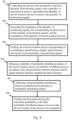
Fig.4 illustrates a flowchart of a dynamic power positioning method; and -
Figs.5A-5B illustrate schematic diagrams related to probability distributions of the dynamic power positioning method of the present invention. - In order to make the structure and characteristics as well as the effectiveness of the present invention to be further understood and recognized, the detailed description of the present invention is provided as follows along with embodiments and accompanying figures. Embodiments which do not comprise all features of the independent claims are included for highlighting specific aspects of the invention.
- Please refer to
Fig.1 for a system architecture diagram of the dynamic power positioning system executing a setting process of the present invention. - In an embodiment, the dynamic
power positioning system 1 includes aprocessing module 11, adatabase 12, and acomputing module 13 which are electrically connected with each other. The dynamicpower positioning system 1 is used for finding out a device location of a device to be measured 40 by using a known location device 50 (as shown inFig.3 ) in a space. Before the device to be measured 40 is found, the dynamicpower positioning system 1 can also use atest transmitting device 20 and receivingdevice 30 to establish the required data, but the present invention is not limited thereto. The test transmittingdevice 20, thereceiving device 30, the device to be measured 40, and the knownlocation device 50 can send and receive wireless signals, which can be Bluetooth signals, and thetest transmitting device 20, thereceiving device 30, the device to be measured 40, and the knownlocation device 50 may also be the same or different home appliances, computer devices, or mobile devices, but the present invention is not limited thereto. - It is noted that each module of the dynamic
power positioning system 1 can be constructed by hardware devices, software programs combined with hardware devices, or firmware combined with hardware devices. For example, a computer program product stored in a computer-readable medium can be read to execute various functions of the invention, but the invention is not limited to the above-mentioned manner. In order to implement the present invention, other more detailed conventional modules or components may also be included. Theprocessing module 11, thedatabase 12 or thecomputing module 13 can be disposed in the same device or in different devices, or can be disposed in any one of thetest transmitting device 20, thereceiving device 30, the device to be measured 40, or the knownlocation device 50, but the present invention is not limited thereto. - Therefore, in an embodiment of the present invention, the
processing module 11 sets a plurality of transmission powers of thetest transmitting device 20, so thetest transmitting device 20 can transmit a plurality of test signals. Then theprocessing module 11 makes thereceiving device 30 to receive the plurality of test signals at a plurality of corresponding distances from thetest transmitting device 20, for example, at a distance of 10 cm, 20 cm, or 1 m to 6 m, wherein different test signals are transmitted with different transmission powers. However, the present invention is not limited to the values stated above. Accordingly, theprocessing module 11 detects and obtains the plurality of test signal intensities received by thereceiving device 30, so as to record the plurality of test signal intensities and the plurality of corresponding distances to thedatabase 12. Finally, thecomputing module 13 calculates the signal intensity-distance function and the signal intensity-distance standard deviation function based on the values of thedatabase 12, and stores them back to thedatabase 12. - Now please refer to
Fig.2 for a flowchart of the data setting process of the present invention. It is noted that although the dynamicpower positioning system 1 described above is used as an example to describe the data setting process of the present invention, the data setting process of the present invention is limited to the use of a dynamicpower positioning system 1 according to claim 5. - First, the method proceeds to step 201: setting a plurality of transmission powers of a test transmitting device, so that the test transmitting device transmits a plurality of test signals to a receiving device at a plurality of corresponding distances.
- First, the
processing module 11 sets a plurality of transmission powers of thetest transmitting device 20. Therefore, thetest transmitting device 20 can transmit a plurality of test signals, and then thereceiving device 30 receives the plurality of test signals at different distances of, for example, 10 cm, 20 cm, or 1 meter to 6 meters from thetest transmitting device 20. - Then the method proceeds to step 202: detecting the plurality of test signal intensities received by the receiving device.
- Then the
processing module 11 detects all the test signal intensities received by thereceiving device 30. - Then the method proceeds to step 203: recording the plurality of test signal intensities of the test signals and the plurality of corresponding distances to a database.
- Then the
processing module 11 records all the test signal intensities of the test signals and the corresponding distances to thedatabase 12. - Finally the method proceeds to step 204: calculating and storing a signal intensity-distance function and a signal intensity-distance standard deviation function to the database.
- Finally, the
computing module 13 can calculate a signal intensity-distance function and a signal intensity-distance standard deviation function for each transmission power according to all the signal intensities of the test signals and the corresponding distances, so that thecomputing module 13 can obtain the relationship between the signal intensity received by thereceiving device 30 and the distance between thereceiving device 30 and thetest transmitting device 20, and its standard deviation. This relationship can be stored in thedatabase 12. In this way, the data setting process of the present invention is completed. - Next, please refer to
Fig.3 for a system architecture diagram of the dynamic power positioning system executing a positioning process of the present invention. - After establishing the signal intensity-distance function and the signal intensity-distance standard deviation function in the
database 12, the dynamicpower positioning system 1 can useknown location devices 50 to find a device location of the device to be measured 40 in the space. It is noted that although in one embodiment of the present invention, the signal intensity-distance function and the signal intensity-distance standard deviation function are obtained by directly performing the data setting process first, the present invention is not limited to performing the data setting process every time to re-create the signal intensity-distance function and the signal intensity-distance standard deviation function in thedatabase 12. The signal intensity-distance function and the signal - intensity-distance standard deviation function can be preset in the device to be measured 40 or the
known location device 50. - Hence, the
processing module 11 controls the device to be measured 40 to transmit a plurality of positioning signals with a plurality of transmission powers, and makes the plurality of knownlocation devices 50 to receive the plurality of positioning signals and to record the intensities of the plurality of positioning signals, the corresponding reception times of the plurality of positioning signals, and the locations of the plurality ofknown location device 50 to thedatabase 12. The plurality of knownlocation devices 50 also receive an identification code of the device to be measured 40, thereby identifying the device to be measured 40. This identification code is also stored in thedatabase 12. Therefore, theprocessing module 11 finds out known devices with higher signal intensities, such as the knownlocation devices computing module 13 can find out the location of the device to be measured 40 by the signal intensity-distance function and the signal intensity - distance standard deviation function based on the device locations ofknown location devices - For a detailed description of the method of finding the device location of the device to be measured 40, please refer to
Fig.4 for a flowchart of a dynamic power positioning method. - First the method proceeds to step 401: controlling the device to be measured to transmit a plurality of positioning signals with a plurality of transmission powers, and making the plurality of known location devices to receive the plurality of positioning signals.
- First, when the device to be measured 40 enters a space, the
processing module 11 must first control the device to be measured 40 to transmit a plurality of positioning signals with different transmission powers, so that the plurality of knownlocation devices 50 can receive the plurality of positioning signal of the device to be measured 40. The plurality of knownlocation devices 50 also receives an identification code of the device to be measured 40. - Then the method proceeds to step 402: recording the intensities of the plurality of positioning signals, the corresponding reception times of the plurality of positioning signals, and the coordinates of the plurality of known location devices.
- Since the device to be measured 40 transmits the plurality of positioning signals with different transmission powers, after the plurality of known
location devices 50 receives the positioning signals, the knownlocation device 50 will send all the intensities of the plurality of positioning signals, the corresponding reception times of the plurality of positioning signals, and the coordinates of the plurality of known location devices to thedatabase 12. - Then the method proceeds to step 403: finding out a known location device corresponding to a positioning signal having a higher signal intensity among the received plurality of positioning signals.
- The
processing module 11 will find out the knownlocation devices database 12. - Then the method proceeds to step 404: obtaining a plurality of probability distribution planes of the known location device at a plurality of different powers according to the signal intensity-distance function and the signal intensity-distance standard deviation function.
- The
computing module 13 can then query the signal intensity-distance function and the signal intensity-distance standard deviation function according to the intensities of the plurality of positioning signals, the corresponding reception times of the plurality of positioning signals, and the coordinates of the plurality of known location devices having higher signal intensities, by using the fixed coordinates of knownlocation device location devices - At this time, please refer to
Figs.5A-5B are base toFig.4 , to illustrate schematic diagrams related to probability distributions of the dynamic power positioning method of the present invention. - For example, in this embodiment, the nine probability distribution planes A1 to A9 that are possible for the plurality of positioning signals received by the known
location devices location devices location devices location devices - Then the method proceeds to step 405: obtaining a final probability distribution plane by multiplying the plurality of probability distribution planes.
- Next, the
computing module 13 multiplies the nine probability distribution planes A1 to A9, that is, the probability distribution planes A1 to A3 are first multiplied to obtain the calculated probability distribution plane B1, the probability distribution planes A4 to A6 are multiplied to obtain the calculated probability distribution plane B2, and the probability distribution planes A7 to A9 are multiplied to obtain the calculated probability distribution plane B3. Finally, the calculated probability distribution planes B1 to B3 are multiplied to obtain the final probability distribution plane C1. - Finally the method proceeds to step 406: finding out the location having the maximum probability in the final probability distribution plane to be set as the device location of the device to be measured.
- Finally, the
computing module 13 finds out the location having the maximum probability from the final probability distribution plane C1, and sets the location having the maximum probability as the device location 41 of the device to be measured 40, and the coordinate of the device to be measured 40 can be obtained. - It is noted that the dynamic power positioning method of the present invention is not limited to the above-mentioned order of steps, as long as the purpose of the present invention can be achieved, the above-mentioned order of steps can also be changed.
- By using the dynamic power positioning method and the dynamic
power positioning system 1 of the present invention, the position of the device to be measured 40 can be effectively found without installing any additional sensing modules. - Moreover, the embodiments merely described preferred embodiments of the present invention, and the present invention is not to be construed as being limited by these embodiments. To avoid redundant description, not all possible variations and combination are recited in detail.
Claims (8)
- A dynamic power positioning method used in a dynamic power positioning system (1) to find out a device location (41) of a device to be measured (40) in a space, wherein the space further comprises a plurality of known location devices (50), the method comprises the steps of:controlling the device to be measured (40) to transmit a plurality of positioning signals with a plurality of transmission powers;making the plurality of known location devices (50) to receive the plurality of positioning signals, and recording intensities of the plurality of positioning signals, corresponding reception times of the plurality of positioning signals, and coordinates of the plurality of known location devices (50) to a database;finding out a plurality of known location devices (51, 52, 53) corresponding to positioning signals having a higher signal intensity among the received plurality of positioning signals;obtaining a signal intensity-distance function and a signal intensity-distance standard deviation function from the database (12); andfinding out the device location (41) of the device to be measured (40) according to the signal intensity-distance function and the signal intensity-distance standard deviation function; wherein the step of finding out the device location (41) of the device to be measured (40) is performed by querying the signal intensity-distance function and the signal intensity-distance standard deviation function based on the intensities of the plurality of positioning signals, the corresponding reception times of the plurality of positioning signals, and the coordinates of the plurality of known location devices (51, 52, 53) with higher signal intensities;wherein the dynamic power positioning method further comprises the following step of:obtaining a plurality of probability distribution planes (A1) of the plurality of known location devices (51, 52, 53) with higher signal intensities at a plurality of different powers according to the signal intensity-distance function and the signal intensity-distance standard deviation function;obtaining a final probability distribution plane (C1) by multiplying the plurality of probability distribution planes (A1) with each other; andfinding out a location having a maximum probability in the final probability distribution plane (C1) to be set as the device location (41) of the device to be measured (40).
- The dynamic power positioning method as claimed in Claim 1 further comprising the step of finding out three known location devices (50) with higher signal intensities.
- The dynamic power positioning method as claimed in Claim 1 further comprising the step of receiving an identification code of the device to be measured (40).
- The dynamic power positioning method as claimed in Claim 1 further comprising a step of performing a data setting process, wherein the data setting process comprises:setting a plurality of transmission powers of a test transmitting device (20) so that the test transmitting device (20) transmits a plurality of different test signals to a receiving device (30) at a plurality of corresponding distances, wherein the different test signals correspond to different transmission powers;detecting intensities of the plurality of test signals received by the receiving device (30);recording the intensities of the plurality of test signals and the plurality of corresponding distances to the database (12);calculating the signal intensity-distance function and the signal intensity-distance standard deviation function for each transmission power according to the intensities of the plurality of test signals and the plurality of corresponding distances; andstoring the signal intensity-distance function and the signal intensity-distance standard deviation function to the database (12).
- A dynamic power positioning system (1) for finding out a device location (41) of a device to be measured (40) in a space, wherein the space further comprises a plurality of known location devices (50), the dynamic power positioning system (1) comprises:a processing module (11) configured for controlling the device to be measured (40) to transmit a plurality of positioning signals with a plurality of transmission powers, and making the plurality of known location devices (50) to receive the plurality of positioning signals;a database (12) electrically connected with the processing module (11) and used for storing a signal intensity-distance function and a signal intensity-distance standard deviation function, and recording intensities of the plurality of positioning signals, corresponding reception times of the plurality of positioning signals, and coordinates of the plurality of known location devices (50) after the plurality of known location devices (50) has received the plurality of positioning signals, so that the processing module (11) finds out a plurality of known location devices (51, 52, 53) corresponding to positioning signals having a higher signal intensity among the received plurality of positioning signals; anda computing module (13) electrically connected with the database (12) and configured for finding out the device location (41) of the device to be measured (40) by querying the signal intensity-distance function and the signal intensity-distance standard deviation function based on the intensities of the plurality of positioning signals, the corresponding reception times of the plurality of positioning signals, and the coordinates of the plurality of known location devices (51, 52, 53) with higher signal intensities;wherein the processing module (11) obtains plurality of probability distribution planes (A1) of the plurality of known location device (51, 52, 53) with higher signal intensitites at a plurality of different powers according to the signal intensity-distance function and the signal intensity-distance standard deviation function, obtains a final probability distribution plane (C1) by multiplying the plurality of probability distribution planes (A1) with each other, and finds out a location having a maximum probability in the final probability distribution plane (C1) to be set as the device location (41) of the device to be measured (40).
- The dynamic power positioning system (1) as claimed in Claim 5, wherein the processing module (11) is used for finding out three known location devices (50) with higher signal intensities.
- The dynamic power positioning system (1) as claimed in Claim 5, wherein the dynamic power positioning system (1) is provided for receiving an identification code of the device to be measured (40).
- The dynamic power positioning system (1) as claimed in Claim 5, wherein the processing module (11) sets a plurality of transmission powers of a test transmitting device (20) so that the test transmitting device (20) transmits a plurality of different test signals to a receiving device (30) at a plurality of corresponding distances, wherein the different test signals correspond to different transmission powers, when the processing module (11) detects the intensities of the plurality of test signals received by the receiving device (30), the processing module (11) records the intensities of the plurality of test signals and the plurality of corresponding distances to the database (12) so that the computing module (13) calculates the signal intensity-distance function and the signal intensity-distance standard deviation function for each transmission power according to the intensities of the plurality of test signals and the plurality of corresponding distances and stores the signal intensity-distance function and the signal intensity-distance standard deviation function to the database.
Applications Claiming Priority (1)
| Application Number | Priority Date | Filing Date | Title |
|---|---|---|---|
| TW108145554A TWI708957B (en) | 2019-12-12 | 2019-12-12 | Dynamic power positioning method and dynamic power positioning system thereof |
Publications (2)
| Publication Number | Publication Date |
|---|---|
| EP3835808A1 EP3835808A1 (en) | 2021-06-16 |
| EP3835808B1 true EP3835808B1 (en) | 2024-06-26 |
Family
ID=73039848
Family Applications (1)
| Application Number | Title | Priority Date | Filing Date |
|---|---|---|---|
| EP20204620.7A Active EP3835808B1 (en) | 2019-12-12 | 2020-10-29 | Dynamic power positioning method and dynamic power positioning system |
Country Status (3)
| Country | Link |
|---|---|
| EP (1) | EP3835808B1 (en) |
| JP (1) | JP7383577B2 (en) |
| TW (1) | TWI708957B (en) |
Families Citing this family (2)
| Publication number | Priority date | Publication date | Assignee | Title |
|---|---|---|---|---|
| CN113009415B (en) * | 2019-12-19 | 2024-05-17 | 聚众联合科技股份有限公司 | Dynamic power positioning method and dynamic power positioning system thereof |
| TWI774140B (en) * | 2020-11-26 | 2022-08-11 | 聚眾聯合科技股份有限公司 | Two-way signal positioning method and two-way signal positioning system thereof |
Family Cites Families (13)
| Publication number | Priority date | Publication date | Assignee | Title |
|---|---|---|---|---|
| US6425086B1 (en) * | 1999-04-30 | 2002-07-23 | Intel Corporation | Method and apparatus for dynamic power control of a low power processor |
| US7971074B2 (en) * | 2007-06-28 | 2011-06-28 | Intel Corporation | Method, system, and apparatus for a core activity detector to facilitate dynamic power management in a distributed system |
| JP5240691B2 (en) | 2009-03-31 | 2013-07-17 | 株式会社国際電気通信基礎技術研究所 | Owner identification system |
| US8576123B2 (en) * | 2010-06-29 | 2013-11-05 | International Business Machines Corporation | Method and system for vessel authentication and location validation |
| EP2469298B1 (en) | 2010-12-23 | 2015-02-18 | Televic Healthcare NV | Method and device for determining location of a target |
| US9081080B2 (en) * | 2011-03-04 | 2015-07-14 | Qualcomm Incorporated | RSSI-based indoor positioning in the presence of dynamic transmission power control access points |
| CN102426358B (en) * | 2011-09-05 | 2013-06-26 | 西安电子科技大学 | Multi-beam transmitting power dynamic allocation method used for radar multiple target tracking |
| US9671857B2 (en) * | 2014-03-25 | 2017-06-06 | Qualcomm Incorporated | Apparatus, system and method for dynamic power management across heterogeneous processors in a shared power domain |
| US9874922B2 (en) * | 2015-02-17 | 2018-01-23 | Intel Corporation | Performing dynamic power control of platform devices |
| CN106291487B (en) * | 2016-08-04 | 2019-01-08 | 上海无线电设备研究所 | It is a kind of that power and RCS estimation method are received based on the radar of AGC voltage and echo data |
| US10129700B2 (en) * | 2016-11-14 | 2018-11-13 | WiSilica Inc. | Prediction algorithm for location estimation |
| JP6597918B2 (en) * | 2017-01-20 | 2019-10-30 | 株式会社村田製作所 | Position detection system |
| CN109275096A (en) * | 2018-11-16 | 2019-01-25 | 电子科技大学 | Indoor positioning method based on dynamic matching of multi-layer fusion network |
-
2019
- 2019-12-12 TW TW108145554A patent/TWI708957B/en active
-
2020
- 2020-07-06 JP JP2020116220A patent/JP7383577B2/en active Active
- 2020-10-29 EP EP20204620.7A patent/EP3835808B1/en active Active
Also Published As
| Publication number | Publication date |
|---|---|
| JP7383577B2 (en) | 2023-11-20 |
| TWI708957B (en) | 2020-11-01 |
| EP3835808A1 (en) | 2021-06-16 |
| JP2021096221A (en) | 2021-06-24 |
| TW202122825A (en) | 2021-06-16 |
Similar Documents
| Publication | Publication Date | Title |
|---|---|---|
| EP3842820B1 (en) | Power positioning method and power positioning device | |
| US7729880B1 (en) | Wireless vehicle service systems using addressable devices | |
| US9681268B2 (en) | Mobile device position detection | |
| EP3954050B1 (en) | Electronic device for performing ranging and method thereof | |
| CN103560813B (en) | Mobile terminal positioning method and device based on Bluetooth technology | |
| CN111829525A (en) | UWB indoor and outdoor integrated intelligent navigation and positioning method and system | |
| EP3835808A1 (en) | Dynamic power positioning method and dynamic power positioning system | |
| CN112799108A (en) | Satellite direction positioning method and system applied to satellite communication mode | |
| CN106383458B (en) | Universal wireless control method and system for electrical equipment | |
| US11454695B2 (en) | Dynamic power positioning method and dynamic power positioning system thereof | |
| EP4006569B1 (en) | Two-way signal positioning method and two-way signal positioning system thereof | |
| CN113009415B (en) | Dynamic power positioning method and dynamic power positioning system thereof | |
| US11265677B2 (en) | Power positioning method and power positioning device thereof | |
| CN114487997B (en) | Relative position positioning system and relative position positioning method thereof | |
| CN202694354U (en) | Precise personnel positioning system based on TOA (Time of Arrival) ranging | |
| CN202632334U (en) | Identification card based on TOA ranging | |
| US20190324113A1 (en) | Positioning apparatus and positioning method | |
| CN116295326B (en) | Position determining method, device, system, computer equipment and storage medium | |
| US20220066029A1 (en) | Method and Apparatus for Measuring Discrete Locations Around Perimeter of Swimming Pools | |
| CN114245307A (en) | Positioning method and device for robot, electronic equipment and storage medium | |
| KR102203391B1 (en) | Position Recognition Method and System for a Vehicular Terminals | |
| CN120722278A (en) | A multi-point positioning method and system based on signal strength | |
| HK1244387A1 (en) | Indoor bluetooth positioning method and system |
Legal Events
| Date | Code | Title | Description |
|---|---|---|---|
| PUAI | Public reference made under article 153(3) epc to a published international application that has entered the european phase |
Free format text: ORIGINAL CODE: 0009012 |
|
| STAA | Information on the status of an ep patent application or granted ep patent |
Free format text: STATUS: THE APPLICATION HAS BEEN PUBLISHED |
|
| AK | Designated contracting states |
Kind code of ref document: A1 Designated state(s): AL AT BE BG CH CY CZ DE DK EE ES FI FR GB GR HR HU IE IS IT LI LT LU LV MC MK MT NL NO PL PT RO RS SE SI SK SM TR |
|
| STAA | Information on the status of an ep patent application or granted ep patent |
Free format text: STATUS: REQUEST FOR EXAMINATION WAS MADE |
|
| 17P | Request for examination filed |
Effective date: 20211216 |
|
| RBV | Designated contracting states (corrected) |
Designated state(s): AL AT BE BG CH CY CZ DE DK EE ES FI FR GB GR HR HU IE IS IT LI LT LU LV MC MK MT NL NO PL PT RO RS SE SI SK SM TR |
|
| GRAP | Despatch of communication of intention to grant a patent |
Free format text: ORIGINAL CODE: EPIDOSNIGR1 |
|
| STAA | Information on the status of an ep patent application or granted ep patent |
Free format text: STATUS: GRANT OF PATENT IS INTENDED |
|
| INTG | Intention to grant announced |
Effective date: 20240221 |
|
| GRAS | Grant fee paid |
Free format text: ORIGINAL CODE: EPIDOSNIGR3 |
|
| GRAA | (expected) grant |
Free format text: ORIGINAL CODE: 0009210 |
|
| STAA | Information on the status of an ep patent application or granted ep patent |
Free format text: STATUS: THE PATENT HAS BEEN GRANTED |
|
| AK | Designated contracting states |
Kind code of ref document: B1 Designated state(s): AL AT BE BG CH CY CZ DE DK EE ES FI FR GB GR HR HU IE IS IT LI LT LU LV MC MK MT NL NO PL PT RO RS SE SI SK SM TR |
|
| REG | Reference to a national code |
Ref country code: GB Ref legal event code: FG4D |
|
| REG | Reference to a national code |
Ref country code: CH Ref legal event code: EP |
|
| REG | Reference to a national code |
Ref country code: DE Ref legal event code: R096 Ref document number: 602020032902 Country of ref document: DE |
|
| PG25 | Lapsed in a contracting state [announced via postgrant information from national office to epo] |
Ref country code: BG Free format text: LAPSE BECAUSE OF FAILURE TO SUBMIT A TRANSLATION OF THE DESCRIPTION OR TO PAY THE FEE WITHIN THE PRESCRIBED TIME-LIMIT Effective date: 20240626 |
|
| PG25 | Lapsed in a contracting state [announced via postgrant information from national office to epo] |
Ref country code: FI Free format text: LAPSE BECAUSE OF FAILURE TO SUBMIT A TRANSLATION OF THE DESCRIPTION OR TO PAY THE FEE WITHIN THE PRESCRIBED TIME-LIMIT Effective date: 20240626 Ref country code: HR Free format text: LAPSE BECAUSE OF FAILURE TO SUBMIT A TRANSLATION OF THE DESCRIPTION OR TO PAY THE FEE WITHIN THE PRESCRIBED TIME-LIMIT Effective date: 20240626 |
|
| REG | Reference to a national code |
Ref country code: LT Ref legal event code: MG9D |
|
| PG25 | Lapsed in a contracting state [announced via postgrant information from national office to epo] |
Ref country code: GR Free format text: LAPSE BECAUSE OF FAILURE TO SUBMIT A TRANSLATION OF THE DESCRIPTION OR TO PAY THE FEE WITHIN THE PRESCRIBED TIME-LIMIT Effective date: 20240927 |
|
| PG25 | Lapsed in a contracting state [announced via postgrant information from national office to epo] |
Ref country code: LV Free format text: LAPSE BECAUSE OF FAILURE TO SUBMIT A TRANSLATION OF THE DESCRIPTION OR TO PAY THE FEE WITHIN THE PRESCRIBED TIME-LIMIT Effective date: 20240626 |
|
| REG | Reference to a national code |
Ref country code: NL Ref legal event code: MP Effective date: 20240626 |
|
| PG25 | Lapsed in a contracting state [announced via postgrant information from national office to epo] |
Ref country code: NO Free format text: LAPSE BECAUSE OF FAILURE TO SUBMIT A TRANSLATION OF THE DESCRIPTION OR TO PAY THE FEE WITHIN THE PRESCRIBED TIME-LIMIT Effective date: 20240926 Ref country code: LV Free format text: LAPSE BECAUSE OF FAILURE TO SUBMIT A TRANSLATION OF THE DESCRIPTION OR TO PAY THE FEE WITHIN THE PRESCRIBED TIME-LIMIT Effective date: 20240626 Ref country code: HR Free format text: LAPSE BECAUSE OF FAILURE TO SUBMIT A TRANSLATION OF THE DESCRIPTION OR TO PAY THE FEE WITHIN THE PRESCRIBED TIME-LIMIT Effective date: 20240626 Ref country code: GR Free format text: LAPSE BECAUSE OF FAILURE TO SUBMIT A TRANSLATION OF THE DESCRIPTION OR TO PAY THE FEE WITHIN THE PRESCRIBED TIME-LIMIT Effective date: 20240927 Ref country code: FI Free format text: LAPSE BECAUSE OF FAILURE TO SUBMIT A TRANSLATION OF THE DESCRIPTION OR TO PAY THE FEE WITHIN THE PRESCRIBED TIME-LIMIT Effective date: 20240626 Ref country code: BG Free format text: LAPSE BECAUSE OF FAILURE TO SUBMIT A TRANSLATION OF THE DESCRIPTION OR TO PAY THE FEE WITHIN THE PRESCRIBED TIME-LIMIT Effective date: 20240626 Ref country code: RS Free format text: LAPSE BECAUSE OF FAILURE TO SUBMIT A TRANSLATION OF THE DESCRIPTION OR TO PAY THE FEE WITHIN THE PRESCRIBED TIME-LIMIT Effective date: 20240926 |
|
| PG25 | Lapsed in a contracting state [announced via postgrant information from national office to epo] |
Ref country code: NL Free format text: LAPSE BECAUSE OF FAILURE TO SUBMIT A TRANSLATION OF THE DESCRIPTION OR TO PAY THE FEE WITHIN THE PRESCRIBED TIME-LIMIT Effective date: 20240626 |
|
| REG | Reference to a national code |
Ref country code: AT Ref legal event code: MK05 Ref document number: 1698147 Country of ref document: AT Kind code of ref document: T Effective date: 20240626 |
|
| PG25 | Lapsed in a contracting state [announced via postgrant information from national office to epo] |
Ref country code: NL Free format text: LAPSE BECAUSE OF FAILURE TO SUBMIT A TRANSLATION OF THE DESCRIPTION OR TO PAY THE FEE WITHIN THE PRESCRIBED TIME-LIMIT Effective date: 20240626 |
|
| PG25 | Lapsed in a contracting state [announced via postgrant information from national office to epo] |
Ref country code: PT Free format text: LAPSE BECAUSE OF FAILURE TO SUBMIT A TRANSLATION OF THE DESCRIPTION OR TO PAY THE FEE WITHIN THE PRESCRIBED TIME-LIMIT Effective date: 20241028 |
|
| PG25 | Lapsed in a contracting state [announced via postgrant information from national office to epo] |
Ref country code: PT Free format text: LAPSE BECAUSE OF FAILURE TO SUBMIT A TRANSLATION OF THE DESCRIPTION OR TO PAY THE FEE WITHIN THE PRESCRIBED TIME-LIMIT Effective date: 20241028 |
|
| PGFP | Annual fee paid to national office [announced via postgrant information from national office to epo] |
Ref country code: DE Payment date: 20241025 Year of fee payment: 5 |
|
| PG25 | Lapsed in a contracting state [announced via postgrant information from national office to epo] |
Ref country code: PL Free format text: LAPSE BECAUSE OF FAILURE TO SUBMIT A TRANSLATION OF THE DESCRIPTION OR TO PAY THE FEE WITHIN THE PRESCRIBED TIME-LIMIT Effective date: 20240626 |
|
| PGFP | Annual fee paid to national office [announced via postgrant information from national office to epo] |
Ref country code: GB Payment date: 20241024 Year of fee payment: 5 |
|
| PG25 | Lapsed in a contracting state [announced via postgrant information from national office to epo] |
Ref country code: EE Free format text: LAPSE BECAUSE OF FAILURE TO SUBMIT A TRANSLATION OF THE DESCRIPTION OR TO PAY THE FEE WITHIN THE PRESCRIBED TIME-LIMIT Effective date: 20240626 |
|
| PG25 | Lapsed in a contracting state [announced via postgrant information from national office to epo] |
Ref country code: AT Free format text: LAPSE BECAUSE OF FAILURE TO SUBMIT A TRANSLATION OF THE DESCRIPTION OR TO PAY THE FEE WITHIN THE PRESCRIBED TIME-LIMIT Effective date: 20240626 Ref country code: IS Free format text: LAPSE BECAUSE OF FAILURE TO SUBMIT A TRANSLATION OF THE DESCRIPTION OR TO PAY THE FEE WITHIN THE PRESCRIBED TIME-LIMIT Effective date: 20241026 |
|
| PGFP | Annual fee paid to national office [announced via postgrant information from national office to epo] |
Ref country code: FR Payment date: 20241025 Year of fee payment: 5 |
|
| PG25 | Lapsed in a contracting state [announced via postgrant information from national office to epo] |
Ref country code: CZ Free format text: LAPSE BECAUSE OF FAILURE TO SUBMIT A TRANSLATION OF THE DESCRIPTION OR TO PAY THE FEE WITHIN THE PRESCRIBED TIME-LIMIT Effective date: 20240626 |
|
| PG25 | Lapsed in a contracting state [announced via postgrant information from national office to epo] |
Ref country code: RO Free format text: LAPSE BECAUSE OF FAILURE TO SUBMIT A TRANSLATION OF THE DESCRIPTION OR TO PAY THE FEE WITHIN THE PRESCRIBED TIME-LIMIT Effective date: 20240626 Ref country code: SK Free format text: LAPSE BECAUSE OF FAILURE TO SUBMIT A TRANSLATION OF THE DESCRIPTION OR TO PAY THE FEE WITHIN THE PRESCRIBED TIME-LIMIT Effective date: 20240626 |
|
| PG25 | Lapsed in a contracting state [announced via postgrant information from national office to epo] |
Ref country code: SM Free format text: LAPSE BECAUSE OF FAILURE TO SUBMIT A TRANSLATION OF THE DESCRIPTION OR TO PAY THE FEE WITHIN THE PRESCRIBED TIME-LIMIT Effective date: 20240626 Ref country code: ES Free format text: LAPSE BECAUSE OF FAILURE TO SUBMIT A TRANSLATION OF THE DESCRIPTION OR TO PAY THE FEE WITHIN THE PRESCRIBED TIME-LIMIT Effective date: 20240626 |
|
| PG25 | Lapsed in a contracting state [announced via postgrant information from national office to epo] |
Ref country code: SM Free format text: LAPSE BECAUSE OF FAILURE TO SUBMIT A TRANSLATION OF THE DESCRIPTION OR TO PAY THE FEE WITHIN THE PRESCRIBED TIME-LIMIT Effective date: 20240626 Ref country code: SK Free format text: LAPSE BECAUSE OF FAILURE TO SUBMIT A TRANSLATION OF THE DESCRIPTION OR TO PAY THE FEE WITHIN THE PRESCRIBED TIME-LIMIT Effective date: 20240626 Ref country code: RO Free format text: LAPSE BECAUSE OF FAILURE TO SUBMIT A TRANSLATION OF THE DESCRIPTION OR TO PAY THE FEE WITHIN THE PRESCRIBED TIME-LIMIT Effective date: 20240626 Ref country code: PL Free format text: LAPSE BECAUSE OF FAILURE TO SUBMIT A TRANSLATION OF THE DESCRIPTION OR TO PAY THE FEE WITHIN THE PRESCRIBED TIME-LIMIT Effective date: 20240626 Ref country code: IS Free format text: LAPSE BECAUSE OF FAILURE TO SUBMIT A TRANSLATION OF THE DESCRIPTION OR TO PAY THE FEE WITHIN THE PRESCRIBED TIME-LIMIT Effective date: 20241026 Ref country code: ES Free format text: LAPSE BECAUSE OF FAILURE TO SUBMIT A TRANSLATION OF THE DESCRIPTION OR TO PAY THE FEE WITHIN THE PRESCRIBED TIME-LIMIT Effective date: 20240626 Ref country code: EE Free format text: LAPSE BECAUSE OF FAILURE TO SUBMIT A TRANSLATION OF THE DESCRIPTION OR TO PAY THE FEE WITHIN THE PRESCRIBED TIME-LIMIT Effective date: 20240626 Ref country code: CZ Free format text: LAPSE BECAUSE OF FAILURE TO SUBMIT A TRANSLATION OF THE DESCRIPTION OR TO PAY THE FEE WITHIN THE PRESCRIBED TIME-LIMIT Effective date: 20240626 Ref country code: AT Free format text: LAPSE BECAUSE OF FAILURE TO SUBMIT A TRANSLATION OF THE DESCRIPTION OR TO PAY THE FEE WITHIN THE PRESCRIBED TIME-LIMIT Effective date: 20240626 |
|
| PG25 | Lapsed in a contracting state [announced via postgrant information from national office to epo] |
Ref country code: IT Free format text: LAPSE BECAUSE OF FAILURE TO SUBMIT A TRANSLATION OF THE DESCRIPTION OR TO PAY THE FEE WITHIN THE PRESCRIBED TIME-LIMIT Effective date: 20240626 |
|
| REG | Reference to a national code |
Ref country code: DE Ref legal event code: R097 Ref document number: 602020032902 Country of ref document: DE |
|
| PG25 | Lapsed in a contracting state [announced via postgrant information from national office to epo] |
Ref country code: DK Free format text: LAPSE BECAUSE OF FAILURE TO SUBMIT A TRANSLATION OF THE DESCRIPTION OR TO PAY THE FEE WITHIN THE PRESCRIBED TIME-LIMIT Effective date: 20240626 |
|
| PLBE | No opposition filed within time limit |
Free format text: ORIGINAL CODE: 0009261 |
|
| STAA | Information on the status of an ep patent application or granted ep patent |
Free format text: STATUS: NO OPPOSITION FILED WITHIN TIME LIMIT |
|
| REG | Reference to a national code |
Ref country code: CH Ref legal event code: PL |
|
| 26N | No opposition filed |
Effective date: 20250327 |
|
| PG25 | Lapsed in a contracting state [announced via postgrant information from national office to epo] |
Ref country code: MC Free format text: LAPSE BECAUSE OF FAILURE TO SUBMIT A TRANSLATION OF THE DESCRIPTION OR TO PAY THE FEE WITHIN THE PRESCRIBED TIME-LIMIT Effective date: 20240626 |
|
| PG25 | Lapsed in a contracting state [announced via postgrant information from national office to epo] |
Ref country code: BE Free format text: LAPSE BECAUSE OF NON-PAYMENT OF DUE FEES Effective date: 20241031 Ref country code: LU Free format text: LAPSE BECAUSE OF NON-PAYMENT OF DUE FEES Effective date: 20241029 |
|
| PG25 | Lapsed in a contracting state [announced via postgrant information from national office to epo] |
Ref country code: CH Free format text: LAPSE BECAUSE OF NON-PAYMENT OF DUE FEES Effective date: 20241031 |
|
| REG | Reference to a national code |
Ref country code: BE Ref legal event code: MM Effective date: 20241031 |
|
| PG25 | Lapsed in a contracting state [announced via postgrant information from national office to epo] |
Ref country code: SE Free format text: LAPSE BECAUSE OF FAILURE TO SUBMIT A TRANSLATION OF THE DESCRIPTION OR TO PAY THE FEE WITHIN THE PRESCRIBED TIME-LIMIT Effective date: 20240626 |
|
| PG25 | Lapsed in a contracting state [announced via postgrant information from national office to epo] |
Ref country code: IE Free format text: LAPSE BECAUSE OF NON-PAYMENT OF DUE FEES Effective date: 20241029 |
|
| PG25 | Lapsed in a contracting state [announced via postgrant information from national office to epo] |
Ref country code: HU Free format text: LAPSE BECAUSE OF FAILURE TO SUBMIT A TRANSLATION OF THE DESCRIPTION OR TO PAY THE FEE WITHIN THE PRESCRIBED TIME-LIMIT; INVALID AB INITIO Effective date: 20201029 |
|
| PG25 | Lapsed in a contracting state [announced via postgrant information from national office to epo] |
Ref country code: CY Free format text: LAPSE BECAUSE OF FAILURE TO SUBMIT A TRANSLATION OF THE DESCRIPTION OR TO PAY THE FEE WITHIN THE PRESCRIBED TIME-LIMIT; INVALID AB INITIO Effective date: 20201029 |