EP3835780B1 - Electromagnetic ultrasonic double-wave transducer - Google Patents
Electromagnetic ultrasonic double-wave transducer Download PDFInfo
- Publication number
- EP3835780B1 EP3835780B1 EP18929244.4A EP18929244A EP3835780B1 EP 3835780 B1 EP3835780 B1 EP 3835780B1 EP 18929244 A EP18929244 A EP 18929244A EP 3835780 B1 EP3835780 B1 EP 3835780B1
- Authority
- EP
- European Patent Office
- Prior art keywords
- permanent magnet
- electromagnetic ultrasonic
- shell
- coil
- wave transducer
- Prior art date
- Legal status (The legal status is an assumption and is not a legal conclusion. Google has not performed a legal analysis and makes no representation as to the accuracy of the status listed.)
- Active
Links
Images


Classifications
-
- G—PHYSICS
- G01—MEASURING; TESTING
- G01D—MEASURING NOT SPECIALLY ADAPTED FOR A SPECIFIC VARIABLE; ARRANGEMENTS FOR MEASURING TWO OR MORE VARIABLES NOT COVERED IN A SINGLE OTHER SUBCLASS; TARIFF METERING APPARATUS; MEASURING OR TESTING NOT OTHERWISE PROVIDED FOR
- G01D5/00—Mechanical means for transferring the output of a sensing member; Means for converting the output of a sensing member to another variable where the form or nature of the sensing member does not constrain the means for converting; Transducers not specially adapted for a specific variable
- G01D5/48—Mechanical means for transferring the output of a sensing member; Means for converting the output of a sensing member to another variable where the form or nature of the sensing member does not constrain the means for converting; Transducers not specially adapted for a specific variable using wave or particle radiation means
- G01D5/50—Mechanical means for transferring the output of a sensing member; Means for converting the output of a sensing member to another variable where the form or nature of the sensing member does not constrain the means for converting; Transducers not specially adapted for a specific variable using wave or particle radiation means derived from a radioactive source
-
- G—PHYSICS
- G01—MEASURING; TESTING
- G01N—INVESTIGATING OR ANALYSING MATERIALS BY DETERMINING THEIR CHEMICAL OR PHYSICAL PROPERTIES
- G01N29/00—Investigating or analysing materials by the use of ultrasonic, sonic or infrasonic waves; Visualisation of the interior of objects by transmitting ultrasonic or sonic waves through the object
- G01N29/22—Details, e.g. general constructional or apparatus details
- G01N29/24—Probes
- G01N29/2412—Probes using the magnetostrictive properties of the material to be examined, e.g. electromagnetic acoustic transducers [EMAT]
-
- G—PHYSICS
- G01—MEASURING; TESTING
- G01L—MEASURING FORCE, STRESS, TORQUE, WORK, MECHANICAL POWER, MECHANICAL EFFICIENCY, OR FLUID PRESSURE
- G01L5/00—Apparatus for, or methods of, measuring force, work, mechanical power, or torque, specially adapted for specific purposes
-
- G—PHYSICS
- G01—MEASURING; TESTING
- G01N—INVESTIGATING OR ANALYSING MATERIALS BY DETERMINING THEIR CHEMICAL OR PHYSICAL PROPERTIES
- G01N29/00—Investigating or analysing materials by the use of ultrasonic, sonic or infrasonic waves; Visualisation of the interior of objects by transmitting ultrasonic or sonic waves through the object
- G01N29/04—Analysing solids
- G01N29/043—Analysing solids in the interior, e.g. by shear waves
-
- G—PHYSICS
- G01—MEASURING; TESTING
- G01N—INVESTIGATING OR ANALYSING MATERIALS BY DETERMINING THEIR CHEMICAL OR PHYSICAL PROPERTIES
- G01N29/00—Investigating or analysing materials by the use of ultrasonic, sonic or infrasonic waves; Visualisation of the interior of objects by transmitting ultrasonic or sonic waves through the object
- G01N29/04—Analysing solids
- G01N29/07—Analysing solids by measuring propagation velocity or propagation time of acoustic waves
-
- G—PHYSICS
- G01—MEASURING; TESTING
- G01N—INVESTIGATING OR ANALYSING MATERIALS BY DETERMINING THEIR CHEMICAL OR PHYSICAL PROPERTIES
- G01N2291/00—Indexing codes associated with group G01N29/00
- G01N2291/02—Indexing codes associated with the analysed material
- G01N2291/028—Material parameters
- G01N2291/02827—Elastic parameters, strength or force
-
- G—PHYSICS
- G01—MEASURING; TESTING
- G01N—INVESTIGATING OR ANALYSING MATERIALS BY DETERMINING THEIR CHEMICAL OR PHYSICAL PROPERTIES
- G01N2291/00—Indexing codes associated with group G01N29/00
- G01N2291/04—Wave modes and trajectories
- G01N2291/042—Wave modes
- G01N2291/0421—Longitudinal waves
-
- G—PHYSICS
- G01—MEASURING; TESTING
- G01N—INVESTIGATING OR ANALYSING MATERIALS BY DETERMINING THEIR CHEMICAL OR PHYSICAL PROPERTIES
- G01N2291/00—Indexing codes associated with group G01N29/00
- G01N2291/04—Wave modes and trajectories
- G01N2291/042—Wave modes
- G01N2291/0422—Shear waves, transverse waves, horizontally polarised waves
-
- G—PHYSICS
- G01—MEASURING; TESTING
- G01N—INVESTIGATING OR ANALYSING MATERIALS BY DETERMINING THEIR CHEMICAL OR PHYSICAL PROPERTIES
- G01N2291/00—Indexing codes associated with group G01N29/00
- G01N2291/26—Scanned objects
- G01N2291/269—Various geometry objects
- G01N2291/2691—Bolts, screws, heads
Definitions
- the invention relates to the technical field of ultrasonic inspection, specifically relating to an electromagnetic ultrasonic double-wave transducer.
- the time-of-flight of the ultrasonic wave is from the change of the part's dimension or the change of the speed of the ultrasonic wave caused by the tensile stress of the bolt.
- the bolt tension cannot be detected by an ultrasonic method.
- the open literature 1 NDT&E International42(2009)164-169 ) mentioned that the ultrasonic longitudinal wave generates mode-converted transverse wave on the reflection bottom surface of the part to be measured by employing a specially designed piezoelectric ultrasonic transducer
- the open literature 2 Ultrasonics 54(2014)914-920 ) mentions that an electromagnetic ultrasonic transverse wave transducer generates mode-converted longitudinal wave at the reflection bottom of the part to be tested by using a high-power source for excitation and a multiple averaging method
- the open literature 3 Vol.17(1996)No.6 662-665, Chinese Journal of Scientific Instrument ) mentions that the ultrasonic longitudinal waves and transverse waves are respectively generated in the testing part by adopting two piezoelectric transducers in combination
- the open literature 4 (US Patent US8511165B2 ) mentions the use of a piezoelectric transducer in combination with an electromagnetic ultrasonic transducer to generate longitudinal and transverse waves, respectively
- None of the methods in the above open literature can generate both longitudinal wave and transverse wave on the surface of the part to be inspected, causing errors in high-precision inspection, particularly in bolt tension inspection.
- the piezoelectric transducers referred to in the open literature 1 to 4 need to take the influence of the wedges and the couplant on the propagation time of the ultrasonic wave during the forward and backward propagation of the ultrasonic wave from the piezoelectric wafer to the surface of the part to be tested.
- Neither of the electromagnetic ultrasonic transducers described in the open literature 2 and 4 can generate ultrasonic longitudinal wave on the surface of a testing part.
- the invention aims at providing an electromagnetic ultrasonic double-wave transducer, which can simultaneously generate longitudinal wave and transverse wave on the surface of a testing part.
- An electromagnetic ultrasonic double-wave transducer comprising a shell, and a permanent magnet assembly, a coil, a shielding layer, and a wire which are provided in said shell.
- Said permanent magnet assembly comprises a first permanent magnet and a second permanent magnet sleeved on the first permanent magnet.
- the magnetizing directions of the first permanent magnet and the second permanent magnet are perpendicular to the bottom of said shell, and the magnetic field directions of said first permanent magnet and the second permanent magnet are opposite;
- a non-conducting non-magnetic bushing material is provided between said first permanent magnet and said second permanent magnet, and upper end faces of said first permanent magnet and said second permanent magnet realize magnetic circuit closing by means of a magnetic circuit closing element.
- Said coil is fixed on the bottom of said shell and is located below said first permanent magnet.
- Said shielding layer is provided between the lower end of said first permanent magnet and said coil and below said second permanent magnet.
- One end of said wire is connected to said coil, and the other end is connected to power supply and signal plug.
- said first permanent magnet is cylindrical while said second permanent magnet is annular.
- the inner diameter of said second permanent magnet is 1-15mm larger than the outer diameter of said first permanent magnet.
- the lower end faces of said first permanent magnet and said second permanent magnet have a height difference from -3mm to 3mm.
- said coil is helical, and the outer diameter thereof is larger than the outer diameter of said first permanent magnet and smaller than the inner diameter of said second permanent magnet.
- the non-conductive material is filled between said coil and said shielding layer, and the non-conducting non-magnetic material is filled between said permanent magnet assembly and said shell.
- said shell includes a shell body and a wear plate disposed at the lower end of said shell body.
- the non-conductive material is filled between said coil and said shielding layer, and the non-conducting non-magnet-conduction material is filled between said permanent magnet assembly and said shell.
- said shell includes a shell body and a wear plate disposed at the lower end of said shell body.
- the invention has following advantages:
- the ultrasonic transducer can simultaneously excite longitudinal waves and transverse waves on the surface of a testing part, and the two modes of ultrasonic waves are used for detecting physical quantities such as material properties like elastic modulus of materials, defects, length, stress and the like, thereby the measurement error caused by the time delay of the piezoelectric ultrasonic wedge and the coupling agent is avoided, the detection error possibly caused by the mode conversion of the ultrasonic waves is also avoided, and the detection precision is improved.
- FIG. 1 a schematic structural diagram of the embodiment in the invention provides an electromagnetic ultrasonic double-wave transducer, comprising a shell 1, and a permanent magnet assembly, a coil 4, a shielding layer 5, and a wire 6 which are provided in the shell 1.
- the permanent magnet assembly comprises a first permanent magnet 2 and a second permanent magnet 3 sleeved on the first permanent magnet 2.
- the magnetizing directions of the first permanent magnet 2 and the second permanent magnet 3 are perpendicular to the bottom of the shell 1, and the magnetic field directions of the first permanent magnet 2 and the second permanent magnet 3 are opposite.
- a non-conducting non-magnetic bushing material 9 is provided between the first permanent magnet 2 and the second permanent magnet 3, and upper end faces of the first permanent magnet 2 and the second permanent magnet 3 realize magnetic circuit closing by means of a magnetic circuit closing element 8.
- Said coil 4 is fixed on the bottom of said shell 1 and is located below said first permanent magnet 2.
- Said shielding layer 5 is provided between the lower end of said first permanent magnet 2 and said coil 4 and below said second permanent magnet 3.
- One end of said wire 6 is connected to said coil 4, and the other end is connected to a power supply and signal plug 7.
- the inner diameter of said second permanent magnet 3 is 1-15mm larger than the outer diameter of said first permanent magnet 2, and said coil 4 is helical, and the outer diameter thereof is larger than the outer diameter of said first permanent magnet 2 and smaller than the inner diameter of said second permanent magnet 3.
- the lower end face of the first permanent magnet 2 can be flush with that of the second permanent magnet 3, and they also can have a height difference of less than 3mm, which means that the lower end face of the first permanent magnet 2 is located above that of the second permanent magnet 3, or is located below that of the second permanent magnet 3.
- the shielding layer 5 is a highly conductive copper sheet or silver sheet, and is attached to the lower ends of the first permanent magnet 2 and the second permanent magnet 3.
- the non-conductive material 10 is filled between said coil 4 and said shielding layer 5, such as air, resin and non-conductive soft magnetic material; the non-conducting non-magnetic material is filled between said permanent magnet assembly and said shell 1, i.e., epoxy resin.
- said coil 4 is made of double-layer PCB board or wound by enameled wire.
- said shell 1 includes a shell body 1-1 and a wear plate 1-2 disposed at the lower end of said shell body 1-1; the wear plate 1-2 is made of ceramic wafer or epoxy plate and the shell body 1-1 is made of stainless steel, aluminum alloy or red copper material; the power supply and signal plug 7 is fixed at the upper part of the shell body 1-1.
- the schematic structural diagram of embodiment 2 is the same as the embodiment 1 except structure of the permanent magnet assembly and structure of the coil 4;
- the permanent magnet assembly comprises a third permanent magnet 12 and a fourth permanent magnet 13 wherein the fourth permanent magnet 13 are arranged side by side with said third permanent magnet 12 and located on two sides of the width direction of said third permanent magnet 12, and between said fourth permanent magnet 13 and said third permanent magnet 12 are non-conducting non-magnetic bushing material 9;
- the cross sections of said third permanent magnet 12 and said fourth permanent magnet 13 are rectangular and said coil 4 is butterfly shaped.
- the first permanent magnet 2, the second permanent magnet 3, the third permanent magnet 12 and the fourth permanent magnet 13 are all made of NdFeB materials.
- the electromagnetic ultrasonic transducer can simultaneously excite vertical downward-transmitted ultrasonic transverse waves and ultrasonic longitudinal waves on the near surface of a conductive or magnetic testing part such as low-carbon steel, aluminum alloy and the like, and the amplitude of the longitudinal waves excited by said electromagnetic ultrasonic transducer can reach 20% to 30% of the transverse waves at most in a test with a matched instrument. While the conventional electromagnetic ultrasonic transducer can hardly excite longitudinal wave.
- the Young's modulus and the Poisson's ratio of isotropic materials were detected by using the electromagnetic ultrasonic double-wave transducer of embodiment 1.
- the Young's modulus and the Poisson's ratio of the material can be estimated by detecting the longitudinal wave velocity, the transverse wave velocity and the density of the material.
- a hand-held high-power ultrasonic testing instrument PREMAT-HS200 manufactured by Suzhou Phaserise Technology Co., Ltd. is used as an electromagnetic ultrasonic pulser/receiver equipped with the electromagnetic ultrasonic double-wave transducer of the invention.
- the testing part is selected from a CSK-IIA standard sample according to JB/T 4730-2005 standard.
- the sample dimension is 300mm long, 60mm wide and 40mm in height
- the electromagnetic ultrasonic transducer is placed in the middle of the upper surface of the sample to be tested, and is 170mm away from the left edge of the sample, and 35mm away from the upper edge.
- the test frequency is 4MHz, the excitation voltage 1200Vpp, the display delay 10 ⁇ s, the sampling time 80 ⁇ s, the sampling speed 100MS/s, and the repetition rate 200Hz.
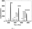
- the test data for the automatic gain is shown in FIG. 4 .
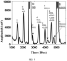
- Increasing the gain further on the basis of FIG. 4 results in FIG. 5 .
- FIG. 5 multiple periodic echoes and mode-converted waves are labeled, and it can be seen that the electromagnetic ultrasonic double-wave transducer of the invention excites longitudinal waves (first echo is LL) and transverse waves (first echo is SS) simultaneously on the surface of the sample.
- Table 1 Time-of-flight of longitudinal wave and transverse wave excited on surface of the testing part.
- LL SS SSSS SSSSSS Average wave velocity of transverse wave Time(ns) 1354.13 24707 49402 74097 3239.5m/s Sound velocity of longitudinal Waves(m/s) 5907.85 -- -- -- --
- the transducer of the invention can be used for accurate detection of bolt tension.
- ⁇ is the clamping length ratio of the bolt, namely the ratio of the length of the bolt under tension to the total length
- E is the Young's modulus
- ⁇ is the acoustic elastic coefficient of the transverse wave
- ⁇ is the acoustic elastic coefficient of the longitudinal waves
- C S0 and C l0 are transverse and longitudinal wave velocities in the absence of tension
- TOFs is the fight time of bolt transverse wave
- TOF l is the fight time of bolt longitudinal wave.
- the tensile stress applied to the bolt can be calculated as long as TOF S and TOF l can be accurately measured.
- the transducer used by the invention can simultaneously excite longitudinal waves and transverse waves on the inspection surface end of the bolt.
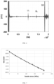
- FIG. 6 is the experimental raw data of TOF S and TOF l ratio versus tensile stress applied to the 42mm-nominal-diameter bolt in FIG. 6 . during calibration by a hydraulic bolt tensile machine.
- the correspondence between the two is a relatively smooth monotonous function in one-to-one correspondence, and the corresponding bolt tensile stress error range is relatively small.
- Professional data processing methods can also be applied to process the one-to-one monotone function shown in the FIG 7 , so as to obtain higher inspection precision for the bolt tensile stress.
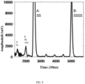
- FIG.8 in embodiment 2 corresponds to FIG. 5 of embodiment 1.
- the amplitude of the longitudinal wave generated simultaneously with the transverse wave on the surface of the testing sample is about one third of that of the embodiment 1, but the final detection results of the Young's modulus and the Poisson's ratio are not much different from that of the embodiment 1.
- the electromagnetic ultrasonic double-wave transducer of embodiment 2 is directional, and is very advantageous for detecting the sound velocity of transverse waves and the longitudinal waves in each direction of a material having a regular texture, such as a cold-rolled steel sheet or an aluminum sheet.
Landscapes
- Physics & Mathematics (AREA)
- General Physics & Mathematics (AREA)
- Biochemistry (AREA)
- Life Sciences & Earth Sciences (AREA)
- Chemical & Material Sciences (AREA)
- Analytical Chemistry (AREA)
- Health & Medical Sciences (AREA)
- General Health & Medical Sciences (AREA)
- Immunology (AREA)
- Pathology (AREA)
- Acoustics & Sound (AREA)
- Electromagnetism (AREA)
- Investigating Or Analyzing Materials By The Use Of Ultrasonic Waves (AREA)
Description
- The invention relates to the technical field of ultrasonic inspection, specifically relating to an electromagnetic ultrasonic double-wave transducer.
- In the field of ultrasonic inspection, it is sometimes necessary to use two modes of waves to accurately detect a part for inspection for certain material properties, dimensions, or defects. For example, in the detection of the nodularity of spheroidal graphite cast iron, if there is only one mode of waves, it is not easy to distinguish whether the change in the time-of-flight is from a change in the thickness of the sample or from a change in the speed of the ultrasonic wave itself, which greatly affects the effectiveness of the inspection. For example, in the assessment of the tensile force of the bolt, if only one mode of ultrasonic wave is adopted, it cannot be known whether the time-of-flight of the ultrasonic wave is from the change of the part's dimension or the change of the speed of the ultrasonic wave caused by the tensile stress of the bolt. Thus, the bolt tension cannot be detected by an ultrasonic method.
- In order to generate ultrasonic waves of two different modes, the open literature 1 (NDT&E International42(2009)164-169) mentioned that the ultrasonic longitudinal wave generates mode-converted transverse wave on the reflection bottom surface of the part to be measured by employing a specially designed piezoelectric ultrasonic transducer; the open literature 2 (Ultrasonics 54(2014)914-920) mentions that an electromagnetic ultrasonic transverse wave transducer generates mode-converted longitudinal wave at the reflection bottom of the part to be tested by using a high-power source for excitation and a multiple averaging method; the open literature 3 (Vol.17(1996)No.6 662-665, Chinese Journal of Scientific Instrument) mentions that the ultrasonic longitudinal waves and transverse waves are respectively generated in the testing part by adopting two piezoelectric transducers in combination; the open literature 4 (US Patent
US8511165B2 ) mentions the use of a piezoelectric transducer in combination with an electromagnetic ultrasonic transducer to generate longitudinal and transverse waves, respectively, on the surface of a testing part.CN104820024A discloses a wave electromagnetic acoustic sensor according to prior art. - None of the methods in the above open literature can generate both longitudinal wave and transverse wave on the surface of the part to be inspected, causing errors in high-precision inspection, particularly in bolt tension inspection. The piezoelectric transducers referred to in the
open literature 1 to 4 need to take the influence of the wedges and the couplant on the propagation time of the ultrasonic wave during the forward and backward propagation of the ultrasonic wave from the piezoelectric wafer to the surface of the part to be tested. Neither of the electromagnetic ultrasonic transducers described in theopen literature - Based on the problems in the prior art, the invention aims at providing an electromagnetic ultrasonic double-wave transducer, which can simultaneously generate longitudinal wave and transverse wave on the surface of a testing part.
- Based on the above problems, the invention provides a technical solution:
- An electromagnetic ultrasonic double-wave transducer according to
claim 1, comprising a shell, and a permanent magnet assembly, a coil, a shielding layer, and a wire which are provided in said shell. - Said permanent magnet assembly comprises a first permanent magnet and a second permanent magnet sleeved on the first permanent magnet. The magnetizing directions of the first permanent magnet and the second permanent magnet are perpendicular to the bottom of said shell, and the magnetic field directions of said first permanent magnet and the second permanent magnet are opposite; a non-conducting non-magnetic bushing material is provided between said first permanent magnet and said second permanent magnet, and upper end faces of said first permanent magnet and said second permanent magnet realize magnetic circuit closing by means of a magnetic circuit closing element.
- Said coil is fixed on the bottom of said shell and is located below said first permanent magnet. Said shielding layer is provided between the lower end of said first permanent magnet and said coil and below said second permanent magnet. One end of said wire is connected to said coil, and the other end is connected to power supply and signal plug.
- In one embodiment, said first permanent magnet is cylindrical while said second permanent magnet is annular.
- In one embodiment, the inner diameter of said second permanent magnet is 1-15mm larger than the outer diameter of said first permanent magnet.
- In one embodiment, the lower end faces of said first permanent magnet and said second permanent magnet have a height difference from -3mm to 3mm.
- In one embodiment, said coil is helical, and the outer diameter thereof is larger than the outer diameter of said first permanent magnet and smaller than the inner diameter of said second permanent magnet.
- In one embodiment, the non-conductive material is filled between said coil and said shielding layer, and the non-conducting non-magnetic material is filled between said permanent magnet assembly and said shell.
- In one embodiment, said shell includes a shell body and a wear plate disposed at the lower end of said shell body.
- In one embodiment, the non-conductive material is filled between said coil and said shielding layer, and the non-conducting non-magnet-conduction material is filled between said permanent magnet assembly and said shell.
- In one embodiment, said shell includes a shell body and a wear plate disposed at the lower end of said shell body.
- Compared with the prior art, the invention has following advantages;
- By adopting the technical solution of the invention, the ultrasonic transducer can simultaneously excite longitudinal waves and transverse waves on the surface of a testing part, and the two modes of ultrasonic waves are used for detecting physical quantities such as material properties like elastic modulus of materials, defects, length, stress and the like, thereby the measurement error caused by the time delay of the piezoelectric ultrasonic wedge and the coupling agent is avoided, the detection error possibly caused by the mode conversion of the ultrasonic waves is also avoided, and the detection precision is improved.
- In order to more clearly illustrate the technical solutions of the embodiments of the invention, the drawings required to be used in the description of the embodiments are briefly introduced below, the drawings in the description are only some embodiments of the invention, and it is obvious for those skilled in the art that other drawings can be obtained according to the drawings without creative efforts.
-
FIG. 1 is a schematic structural diagram illustrating theembodiment 1 of the electromagnetic ultrasonic double-wave transducer in the invention; -
FIG. 2 is a schematic structural diagram ofembodiment 2 of the invention; -
FIG. 3 is a sectional view ofFIG. 2 along line A-A; -
FIG. 4 illustrates that the electromagnetic ultrasonic double-wave transducer ofembodiment 1 simultaneously excites transverse wave signals and longitudinal wave signals when detecting the Young's modulus and the Poisson's ratio of isotropic materials; -
FIG. 5 is an enlarged view illustrating the gain of the electromagnetic ultrasonic double-wave transducer ofembodiment 1 simultaneously excites transverse wave signals and longitudinal wave signals when detecting the Young's modulus and the Poisson's ratio of isotropic materials; -
FIG. 6 is the longitudinal wave signals and the transverse wave signals generated simultaneously when the electromagnetic ultrasonic double-wave transducer ofembodiment 1 detects tension of a bolt; -
FIG. 7 illustrates that time-of-flight ratio of the transverse wave sound to the longitudinal wave sound generated simultaneously when the electromagnetic ultrasonic double-wave transducer ofembodiment 1 is used for bolt tension detection is in one-to-one relationship; -
FIG. 8 is an enlarged view illustrating the gain of the electromagnetic ultrasonic double-wave transducer ofembodiment 2 simultaneously excites transverse wave signals and longitudinal wave signals when detecting the Young's modulus and the Poisson's ratio of isotropic materials;
Wherein:- 1. Shell; 1-1. Shell body; 1-2.Wear plate;
- 2. The first permanent magnet;
- 3. The second permanent magnet;
- 4. Coil;
- 5. Shielding layer;
- 6. Wire;
- 7. Power supply and signal plug;
- 8. Magnetic circuit closing element;
- 9. Non-conducting non-magnetic bushing material;
- 10. Non-conductive material;
- 11. Non-conducting non-magnetic material;
- 12. The third permanent magnet;
- 13. The fourth permanent magnet.
- The above-described solution is further illustrated below with reference to specific embodiments. It should be understood that these embodiments are for illustrative purposes and are not intended to limit the scope of the invention. The conditions used in the embodiments may be further adjusted according to the conditions of the particular manufacturer, and the conditions not specified are generally conditions used in routine experiments.
- As is shown in
FIG. 1 , a schematic structural diagram of the embodiment in the invention provides an electromagnetic ultrasonic double-wave transducer, comprising ashell 1, and a permanent magnet assembly, acoil 4, ashielding layer 5, and awire 6 which are provided in theshell 1. - The permanent magnet assembly comprises a first
permanent magnet 2 and a secondpermanent magnet 3 sleeved on the firstpermanent magnet 2. The magnetizing directions of the firstpermanent magnet 2 and the secondpermanent magnet 3 are perpendicular to the bottom of theshell 1, and the magnetic field directions of the firstpermanent magnet 2 and the secondpermanent magnet 3 are opposite. A non-conductingnon-magnetic bushing material 9 is provided between the firstpermanent magnet 2 and the secondpermanent magnet 3, and upper end faces of the firstpermanent magnet 2 and the secondpermanent magnet 3 realize magnetic circuit closing by means of a magneticcircuit closing element 8. - Said
coil 4 is fixed on the bottom of saidshell 1 and is located below said firstpermanent magnet 2. Said shieldinglayer 5 is provided between the lower end of said firstpermanent magnet 2 and saidcoil 4 and below said secondpermanent magnet 3. One end of saidwire 6 is connected to saidcoil 4, and the other end is connected to a power supply andsignal plug 7. - In this embodiment, the magnetic
circuit closing element 8 is made of mild steel or ferrite with a thickness greater than 3mm. The non-conductingnon-magnetic bushing material 9 is made of plastic, rubber or polymer material, such as bakelite. - The inner diameter of said second
permanent magnet 3 is 1-15mm larger than the outer diameter of said firstpermanent magnet 2, and saidcoil 4 is helical, and the outer diameter thereof is larger than the outer diameter of said firstpermanent magnet 2 and smaller than the inner diameter of said secondpermanent magnet 3. The lower end face of the firstpermanent magnet 2 can be flush with that of the secondpermanent magnet 3, and they also can have a height difference of less than 3mm, which means that the lower end face of the firstpermanent magnet 2 is located above that of the secondpermanent magnet 3, or is located below that of the secondpermanent magnet 3. - In this embodiment, the
shielding layer 5 is a highly conductive copper sheet or silver sheet, and is attached to the lower ends of the firstpermanent magnet 2 and the secondpermanent magnet 3. - In order to further optimize the implementation effect of the invention, the
non-conductive material 10 is filled between saidcoil 4 and saidshielding layer 5, such as air, resin and non-conductive soft magnetic material; the non-conducting non-magnetic material is filled between said permanent magnet assembly and saidshell 1, i.e., epoxy resin. - In this embodiment, said
coil 4 is made of double-layer PCB board or wound by enameled wire. - In this embodiment, said
shell 1 includes a shell body 1-1 and a wear plate 1-2 disposed at the lower end of said shell body 1-1; the wear plate 1-2 is made of ceramic wafer or epoxy plate and the shell body 1-1 is made of stainless steel, aluminum alloy or red copper material; the power supply andsignal plug 7 is fixed at the upper part of the shell body 1-1. - As is shown in
FIG. 2 and 3 , the schematic structural diagram ofembodiment 2 is the same as theembodiment 1 except structure of the permanent magnet assembly and structure of thecoil 4; the permanent magnet assembly comprises a thirdpermanent magnet 12 and a fourthpermanent magnet 13 wherein the fourthpermanent magnet 13 are arranged side by side with said thirdpermanent magnet 12 and located on two sides of the width direction of said thirdpermanent magnet 12, and between said fourthpermanent magnet 13 and said thirdpermanent magnet 12 are non-conductingnon-magnetic bushing material 9; - In this embodiment, the cross sections of said third
permanent magnet 12 and said fourthpermanent magnet 13 are rectangular and saidcoil 4 is butterfly shaped. - In the implementation, the first
permanent magnet 2, the secondpermanent magnet 3, the thirdpermanent magnet 12 and the fourthpermanent magnet 13 are all made of NdFeB materials. - The electromagnetic ultrasonic transducer can simultaneously excite vertical downward-transmitted ultrasonic transverse waves and ultrasonic longitudinal waves on the near surface of a conductive or magnetic testing part such as low-carbon steel, aluminum alloy and the like, and the amplitude of the longitudinal waves excited by said electromagnetic ultrasonic transducer can reach 20% to 30% of the transverse waves at most in a test with a matched instrument. While the conventional electromagnetic ultrasonic transducer can hardly excite longitudinal wave.
- For example, the Young's modulus and the Poisson's ratio of isotropic materials were detected by using the electromagnetic ultrasonic double-wave transducer of
embodiment 1. - In isotropic materials, the elasticity modulus E and Poisson's ratio v are related to the velocity of the longitudinal wave C l and the transverse wave CS as follows:

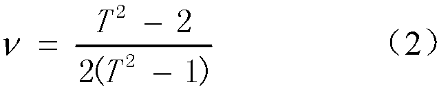
where T is defined as T≡C l /CS, ρ is the density, and taken 7.87×10³kg/m3 for 20# carbon steel. - Therefore, the Young's modulus and the Poisson's ratio of the material can be estimated by detecting the longitudinal wave velocity, the transverse wave velocity and the density of the material.
- A hand-held high-power ultrasonic testing instrument PREMAT-HS200 manufactured by Suzhou Phaserise Technology Co., Ltd. is used as an electromagnetic ultrasonic pulser/receiver equipped with the electromagnetic ultrasonic double-wave transducer of the invention. The testing part is selected from a CSK-IIA standard sample according to JB/T 4730-2005 standard. The sample dimension is 300mm long, 60mm wide and 40mm in height The electromagnetic ultrasonic transducer is placed in the middle of the upper surface of the sample to be tested, and is 170mm away from the left edge of the sample, and 35mm away from the upper edge. The test frequency is 4MHz, the excitation voltage 1200Vpp, the display delay 10µs, the sampling time 80µs, the sampling speed 100MS/s, and the repetition rate 200Hz. The test data for the automatic gain is shown in
FIG. 4 . Increasing the gain further on the basis ofFIG. 4 results inFIG. 5 . InFIG. 5 , multiple periodic echoes and mode-converted waves are labeled, and it can be seen that the electromagnetic ultrasonic double-wave transducer of the invention excites longitudinal waves (first echo is LL) and transverse waves (first echo is SS) simultaneously on the surface of the sample. - Calculations from equations (1) and (2) using the data in table 1 lead to:


- The results are very close to the nominal value of the sample.
Table 1: Time-of-flight of longitudinal wave and transverse wave excited on surface of the testing part. LL SS SSSS SSSSSS Average wave velocity of transverse wave Time(ns) 1354.13 24707 49402 74097 3239.5m/s Sound velocity of longitudinal Waves(m/s) 5907.85 -- -- -- -- - The transducer of the invention can be used for accurate detection of bolt tension. According to the open literature 5(Yuping Shen,G.B.Ma,C.Ma,X.X.Zhu and J.H.Zhao, "Bolt stress inspection by EMAT and PZT",15th Asia Pacific Conference for Non-Destructive Testing, Singapore), the Bolt tension σ can be expressed as

- wherein γ is the clamping length ratio of the bolt, namely the ratio of the length of the bolt under tension to the total length; E is the Young's modulus; α is the acoustic elastic coefficient of the transverse wave; β is the acoustic elastic coefficient of the longitudinal waves; CS0 and Cl0 are transverse and longitudinal wave velocities in the absence of tension; TOFs is the fight time of bolt transverse wave; TOF l is the fight time of bolt longitudinal wave. For the bolt with calibrated material parameters, the tensile stress applied to the bolt can be calculated as long as TOFS and TOF l can be accurately measured. The transducer used by the invention can simultaneously excite longitudinal waves and transverse waves on the inspection surface end of the bolt.
FIG. 6 shows that longitudinal wave (LL) and transverse wave (SS) signals are simultaneously excited on the tested surface end of a bolt with 42mm nominal diameter by using the electromagnetic ultrasonic double-wave transducer of the invention. Thus, TOFs and TOF l values can be simultaneously and accurately measured.FIG. 7 is the experimental raw data of TOFS and TOF l ratio versus tensile stress applied to the 42mm-nominal-diameter bolt inFIG. 6 . during calibration by a hydraulic bolt tensile machine. As can be seen fromFIG.7 , the correspondence between the two is a relatively smooth monotonous function in one-to-one correspondence, and the corresponding bolt tensile stress error range is relatively small. Professional data processing methods can also be applied to process the one-to-one monotone function shown in theFIG 7 , so as to obtain higher inspection precision for the bolt tensile stress. - For instance, Young's modulus and the Poisson's ratio of isotropic materials were measured by using the electromagnetic ultrasonic double-wave transducer of
embodiment 2. - After selecting the same sample and measurement parameters as in
embodiment 1, TheFIG.8 inembodiment 2 corresponds toFIG. 5 ofembodiment 1. InFIG. 8 , the amplitude of the longitudinal wave generated simultaneously with the transverse wave on the surface of the testing sample is about one third of that of theembodiment 1, but the final detection results of the Young's modulus and the Poisson's ratio are not much different from that of theembodiment 1. In addition, the electromagnetic ultrasonic double-wave transducer ofembodiment 2 is directional, and is very advantageous for detecting the sound velocity of transverse waves and the longitudinal waves in each direction of a material having a regular texture, such as a cold-rolled steel sheet or an aluminum sheet. - The above embodiments are provided only for illustrating the technical concepts and features of the invention, and the purpose of the invention is to provide those skilled in the art with the understanding of the invention and to implement the invention, and not to limit the scope of the invention. The scope of the invention is defined by the appended claims.
Claims (7)
- An electromagnetic ultrasonic double wave transducer, comprising a shell (1), and a permanent magnet assembly, a coil (4), a shielding layer (5), a magnetic closing element (8), a power supply and signal plug (7) and a wire (6) which are provided in the shell (1); said permanent magnet assembly comprises a first permanent magnet (2) and a second permanent magnet (3) sleeved on the first permanent magnet (2); the magnetizing directions of the first permanent magnet (2) and the second permanent magnet (3) are perpendicular to the bottom of the shell (1), and the magnetic field directions of the first permanent magnet (2) and the second permanent magnet (3) are opposite; a non-conducting non-magnetic bushing material (9) is provided between the first permanent magnet (2) and the second permanent magnet (3), and upper end faces of the first permanent magnet (2) and the second permanent magnet (3) realize magnetic circuit closing by means of the magnetic circuit closing element (8); said coil (4) is fixed on the bottom of said shell (1) and is located below said first permanent magnet (2); said shielding layer (5) is provided between the lower end of said first permanent magnet (2) and said coil (4) and below said second permanent magnet (3); one end of said wire (6) is connected to said coil (4), and the other end is connected to the power supply and signal plug (7).
- The electromagnetic ultrasonic double-wave transducer of claim 1 wherein said first permanent magnet (2) is cylindrical while said second permanent magnet (3) is annular.
- The electromagnetic ultrasonic double-wave transducer of claim 2 wherein the inner diameter of said second permanent magnet (3) is 1-15mm larger than the outer diameter of said first permanent magnet (2).
- The electromagnetic ultrasonic double-wave transducer of claim 2 wherein the lower end faces of said first permanent magnet (2) and said second permanent magnet (3) have a height difference of -3mm to 3mm.
- The electromagnetic ultrasonic double-wave transducer of claim 2 wherein said coil (4) is helical, and the outer diameter thereof is larger than or equal to the outer diameter of said first permanent magnet (2) and smaller than the inner diameter of said second permanent magnet (3).
- The electromagnetic ultrasonic double-wave transducer of claim 1 wherein a non-conductive material (10) is filled between said coil (4) and said shielding layer (5), and a non-conducting non-magnetic material (11) is filled between said permanent magnet assembly and said shell (1).
- The electromagnetic ultrasonic double-wave transducer of claim 1 wherein said shell (1) includes a shell body (1-1) and a wear plate (1-2) disposed at the lower end of said shell body (1-1).
Applications Claiming Priority (2)
| Application Number | Priority Date | Filing Date | Title |
|---|---|---|---|
| CN201810893704.4A CN108917805B (en) | 2018-08-08 | 2018-08-08 | Electromagnetic ultrasonic wave double wave energy converter |
| PCT/CN2018/112179 WO2020029435A1 (en) | 2018-08-08 | 2018-10-26 | Electromagnetic ultrasonic double-wave transducer |
Publications (3)
| Publication Number | Publication Date |
|---|---|
| EP3835780A1 EP3835780A1 (en) | 2021-06-16 |
| EP3835780A4 EP3835780A4 (en) | 2022-07-20 |
| EP3835780B1 true EP3835780B1 (en) | 2025-04-30 |
Family
ID=64397383
Family Applications (1)
| Application Number | Title | Priority Date | Filing Date |
|---|---|---|---|
| EP18929244.4A Active EP3835780B1 (en) | 2018-08-08 | 2018-10-26 | Electromagnetic ultrasonic double-wave transducer |
Country Status (5)
| Country | Link |
|---|---|
| US (2) | US11959817B2 (en) |
| EP (1) | EP3835780B1 (en) |
| CN (1) | CN108917805B (en) |
| DK (1) | DK3835780T3 (en) |
| WO (1) | WO2020029435A1 (en) |
Families Citing this family (9)
| Publication number | Priority date | Publication date | Assignee | Title |
|---|---|---|---|---|
| CN111239262B (en) * | 2020-03-18 | 2024-12-06 | 桂林电子科技大学 | An omnidirectional SH wave electromagnetic ultrasonic transducer |
| DE102020116174A1 (en) * | 2020-06-18 | 2021-12-23 | Rosen Swiss Ag | Method for the non-destructive testing of, in particular, flat objects made of a fiber composite material |
| CN112033597B (en) * | 2020-08-25 | 2022-05-10 | 苏州博昇科技有限公司 | Ultrasonic dual-wave rapid calibration and detection method for high-strength bolt axial force |
| JP7571572B2 (en) * | 2021-01-26 | 2024-10-23 | 株式会社Soken | Ultrasonic Sensor |
| CN113310805B (en) * | 2021-05-28 | 2023-01-17 | 湖北工业大学 | An Axial Stress Measuring Device with a New Electromagnetic Ultrasonic Longitudinal Wave Transducer |
| CN116793550B (en) * | 2023-02-01 | 2026-05-26 | 零声科技(苏州)有限公司 | Electromagnetic ultrasonic sensor |
| CN116007807B (en) * | 2023-02-01 | 2026-06-05 | 零声科技(苏州)有限公司 | Electromagnetic ultrasonic sensor |
| BE1031841B1 (en) * | 2023-07-28 | 2025-02-26 | Rosenxt Holding Ag | Determination of the integrity of a pipeline wall |
| CN120232563B (en) * | 2025-05-29 | 2025-10-03 | 零声科技(苏州)有限公司 | Integrated double wave transducer |
Family Cites Families (53)
| Publication number | Priority date | Publication date | Assignee | Title |
|---|---|---|---|---|
| US4063157A (en) * | 1976-01-26 | 1977-12-13 | Magnaflux Corporation | Magnetic testing device for internal surfaces of pipe using a magnetizing means and expandable magnetizable material within the pipe |
| US4296486A (en) * | 1980-01-24 | 1981-10-20 | Rockwell International Corporation | Shielded electromagnetic acoustic transducers |
| US4395913A (en) * | 1981-07-31 | 1983-08-02 | Rockwell International Corporation | Broadband electromagnetic acoustic transducers |
| US4471658A (en) * | 1981-09-22 | 1984-09-18 | Mitsubishi Jukogyo Kabushiki Kaisha | Electromagnetic acoustic transducer |
| US4638830A (en) * | 1985-09-27 | 1987-01-27 | Rosemount Inc. | High sensitivity magnetic actuator |
| DE3834248A1 (en) * | 1988-10-05 | 1990-04-12 | Mannesmann Ag | ELECTRODYNAMIC CONVERTER HEAD |
| DE4016740C1 (en) * | 1990-05-21 | 1991-07-04 | Mannesmann Ag, 4000 Duesseldorf, De | |
| DE4035592C1 (en) * | 1990-11-06 | 1992-04-16 | Mannesmann Ag, 4000 Duesseldorf, De | |
| US5277751A (en) * | 1992-06-18 | 1994-01-11 | Ogle John S | Method and apparatus for producing low pressure planar plasma using a coil with its axis parallel to the surface of a coupling window |
| US5608691A (en) * | 1994-05-31 | 1997-03-04 | The Babcock & Wilcox Company | EMAT with integral electrostatic shield |
| US5689070A (en) * | 1995-07-24 | 1997-11-18 | The Babcock & Wilcox Company | High temperature electromagnetic acoustic transducer (EMAT) probe and coil assemblies |
| US5608164A (en) * | 1995-07-27 | 1997-03-04 | The Babcock & Wilcox Company | Electromagnetic acoustic transducer (EMAT) for ultrasonic inspection of liquids in containers |
| US5811682A (en) * | 1995-12-13 | 1998-09-22 | Ebara Corporation | Electromagnetic acoustic transducer EMAT and inspection system with EMAR |
| US6109108A (en) * | 1995-12-13 | 2000-08-29 | Ebara Corporation | Electromagnetic acoustic transducer EMAT and inspection system with EMAR |
| US5900793A (en) * | 1997-07-23 | 1999-05-04 | Odin Technologies Ltd | Permanent magnet assemblies for use in medical applications |
| US6125706A (en) * | 1997-07-25 | 2000-10-03 | Buttram; Jonathan D. | High temperature electromagnetic acoustic transducer |
| JP2000146923A (en) * | 1998-11-05 | 2000-05-26 | Nkk Corp | Ultrasonic measurement of steel |
| EP1299197B1 (en) * | 2000-07-07 | 2005-11-23 | Fraunhofer-Gesellschaft zur Förderung der angewandten Forschung e.V. | Electromagnetic ultrasonic transducer |
| US20030011451A1 (en) * | 2000-08-22 | 2003-01-16 | Ehud Katznelson | Permanent magnet assemblies for use in medical applications |
| JP4083382B2 (en) * | 2000-12-11 | 2008-04-30 | 日本核燃料開発株式会社 | Method for measuring hydrogen concentration in members for nuclear fuel assemblies |
| US7697375B2 (en) * | 2004-03-17 | 2010-04-13 | Baker Hughes Incorporated | Combined electro-magnetic acoustic transducer |
| DE102004053584B4 (en) * | 2004-11-05 | 2006-08-31 | Fraunhofer-Gesellschaft zur Förderung der angewandten Forschung e.V. | Device and method for material testing and / or thickness measurement on an at least electrically conductive and ferromagnetic material components having test object |
| US8247945B2 (en) * | 2005-05-18 | 2012-08-21 | Kolo Technologies, Inc. | Micro-electro-mechanical transducers |
| US7726193B2 (en) * | 2007-09-27 | 2010-06-01 | Baker Hughes Incorporated | Electromagnetic acoustic transducer with cross-talk elimination |
| US8037765B2 (en) * | 2007-11-01 | 2011-10-18 | Baker Hughes Incorporated | Electromagnetic acoustic transducer using magnetic shielding |
| JP5110591B2 (en) * | 2008-07-22 | 2012-12-26 | 独立行政法人日本原子力研究開発機構 | Hybrid measurement apparatus using electromagnetic ultrasonic probe and inspection method using the same |
| DE102008054250A1 (en) * | 2008-10-24 | 2010-04-29 | Institut Dr. Foerster Gmbh & Co. Kg | Electromagnetic-acoustic transducer and ultrasonic test system with it |
| EP2309774B1 (en) * | 2008-11-28 | 2012-08-29 | Olympus Medical Systems Corp. | Ultrasonic transducer, electronic device, and ultrasonic endoscope |
| DE102010023028A1 (en) * | 2010-06-08 | 2011-12-08 | Fraunhofer-Gesellschaft zur Förderung der angewandten Forschung e.V. | EMUS transducer system and a method for generating linearly polarized transverse waves with variably specifiable polarization direction within a test specimen |
| US20120103097A1 (en) * | 2010-10-29 | 2012-05-03 | Borja Lopez Jauregui | Flexible EMAT Arrays for Monitoring Corrosion and Defect Propagation in Metal Components and Structures |
| US8511165B2 (en) * | 2011-03-24 | 2013-08-20 | Borja Lopez Jauregui | Electromagnetic acoustic transducer (EMAT) combined with piezoelectric transducer (PZT) for dual mode ultrasonic inspection |
| JP6071461B2 (en) * | 2012-11-20 | 2017-02-01 | 株式会社東芝 | Material deterioration diagnosis apparatus and material deterioration diagnosis method |
| US9983073B2 (en) * | 2013-07-05 | 2018-05-29 | Torque And More (Tam) Gmbh | Solid borne sound wave phase delay comparison |
| DE102013109331A1 (en) * | 2013-08-28 | 2015-03-05 | Endress + Hauser Gmbh + Co. Kg | Device for determining or monitoring a process variable in automation technology |
| US20150196276A1 (en) * | 2014-01-14 | 2015-07-16 | Samsung Medison Co., Ltd. | Ultrasonic probe and method of manufacturing the same |
| GB201419219D0 (en) * | 2014-10-29 | 2014-12-10 | Imp Innovations Ltd | Electromagnetic accoustic transducer |
| CN104820024B (en) * | 2015-04-27 | 2017-10-13 | 北京工业大学 | A kind of omni-directional A0Mode Lamb wave Electromagnetic Acoustic Transducer |
| CN204854670U (en) * | 2015-06-03 | 2015-12-09 | 衡阳镭目科技有限责任公司 | Electromagnetism ultrasonic sensor and pipeline wall thickness detecting system |
| CN105258659B (en) * | 2015-11-10 | 2018-04-17 | 中国特种设备检测研究院 | Implanted corrosive pipeline monitors electromagnetic ultrasonic transducer on-line |
| CN105675728A (en) * | 2016-02-03 | 2016-06-15 | 中国特种设备检测研究院 | Super-high-temperature electromagnetic acoustic sensor and obtaining method thereof |
| US10408796B2 (en) * | 2016-04-14 | 2019-09-10 | Quest Integrated, Llc | Combined electromagnetic acoustic transducer (EMAT) and electro permanent magnets (EPMS) for bias field control |
| CN105975728A (en) | 2016-05-31 | 2016-09-28 | 济南大学 | Cutting simulation model strain rate verification method based on DEFORM |
| US10436018B2 (en) * | 2016-10-07 | 2019-10-08 | Baker Hughes, A Ge Company, Llc | Downhole electromagnetic acoustic transducer sensors |
| CN107064289B (en) * | 2017-01-18 | 2024-03-29 | 中特检科技发展(北京)有限公司 | Method, device and system for multi-mode electromagnetic ultrasonic and magnetic leakage detection and sensor |
| FR3066593B1 (en) * | 2017-05-17 | 2019-07-12 | Centre Technique Des Industries Mecaniques | ULTRASONIC CLAMPING CONTROL DEVICE AND METHOD USING THE DEVICE |
| CN107064311B (en) * | 2017-06-05 | 2019-08-23 | 哈尔滨工业大学 | An omnidirectional A0 mode Lamb wave electromagnetic ultrasonic transducer |
| JP6875933B2 (en) * | 2017-06-09 | 2021-05-26 | 日立Geニュークリア・エナジー株式会社 | Sensor system |
| US10502714B2 (en) * | 2017-09-28 | 2019-12-10 | Ulc Robotics, Inc. | Electro-magnetic acoustic transducer (EMAT) for both lamb and shear horizontal wave transduction |
| CN108375433A (en) * | 2018-02-28 | 2018-08-07 | 北京金风慧能技术有限公司 | The method and apparatus that the axle power of bolt is detected based on electromagnetic acoustic technology |
| US11442042B2 (en) * | 2018-06-27 | 2022-09-13 | Olympus Scientific Solutions Americas Corp. | Flexible ceramic coil circuit for high temperature non-destructive inspection |
| US20200393417A1 (en) * | 2019-06-12 | 2020-12-17 | Borja Lopez Jauregui | Normal beam emat on components with a bonded magnetostrictive layer |
| CN110873855B (en) * | 2020-01-20 | 2020-04-21 | 华中科技大学 | A pulsed magnet device and high-flux measurement method based on magnetic flux compression |
| US11561205B2 (en) * | 2020-04-30 | 2023-01-24 | Ulc Technologies, Llc | Electro-magnetic acoustic transducer (EMAT) having electromagnet array for generating configurable bias magnetic field patterns |
-
2018
- 2018-08-08 CN CN201810893704.4A patent/CN108917805B/en active Active
- 2018-10-26 EP EP18929244.4A patent/EP3835780B1/en active Active
- 2018-10-26 DK DK18929244.4T patent/DK3835780T3/en active
- 2018-10-26 US US17/266,127 patent/US11959817B2/en active Active
- 2018-10-26 WO PCT/CN2018/112179 patent/WO2020029435A1/en not_active Ceased
-
2024
- 2024-02-24 US US18/586,433 patent/US12449320B2/en active Active
Also Published As
| Publication number | Publication date |
|---|---|
| US20210293639A1 (en) | 2021-09-23 |
| EP3835780A1 (en) | 2021-06-16 |
| EP3835780A4 (en) | 2022-07-20 |
| CN108917805A (en) | 2018-11-30 |
| CN108917805B (en) | 2019-11-26 |
| WO2020029435A1 (en) | 2020-02-13 |
| US11959817B2 (en) | 2024-04-16 |
| US12449320B2 (en) | 2025-10-21 |
| DK3835780T3 (en) | 2025-05-26 |
| US20250052629A1 (en) | 2025-02-13 |
Similar Documents
| Publication | Publication Date | Title |
|---|---|---|
| US12449320B2 (en) | Electromagnetic ultrasonic double-wave transducer | |
| CN109444270B (en) | A composite detection sensor of electromagnetic ultrasonic and pulsed eddy current | |
| JP6362533B2 (en) | Residual stress evaluation method and residual stress evaluation apparatus | |
| KR100561215B1 (en) | Magnetostrictive transducers capable of generating and measuring elastic ultrasonic waves and structural diagnostic devices using them | |
| CN110487908B (en) | Elastic constant measuring method based on array magnet electromagnetic ultrasound | |
| CN117147685A (en) | Electromagnetic Acoustic Transducer (EMAT) for Corrosion Mapping | |
| US20200393417A1 (en) | Normal beam emat on components with a bonded magnetostrictive layer | |
| CN112710417B (en) | Plane stress measurement system and method for unknown thickness of test piece | |
| JP5618223B2 (en) | Ultrasonic flaw detection method and ultrasonic array probe | |
| US12209991B2 (en) | Method and device for non-destructive testing of a plate material | |
| US9689846B2 (en) | Device and method for determining properties of a medium | |
| KR101328061B1 (en) | Magnetostrictive transducer for omni-directional shear horizontal wave transduction | |
| Gori et al. | EMAT transducers and thickness characterization on aged boiler tubes | |
| JP2003130851A (en) | Apparatus for measuring elastic parameters of material surface and coating layer | |
| CN106248790A (en) | A kind of non-metal board Lamb wave detection method based on Electromagnetic Acoustic Transducer | |
| US12372382B2 (en) | Magnetostrictive EMAT for in-motion inspection of railroad wheels | |
| JP4378019B2 (en) | Method of detecting deterioration of metal material by ultrasonic | |
| JP3593055B2 (en) | Ultrasonic probe | |
| JP2009014466A (en) | Electromagnetic ultrasonic probe | |
| KR101558922B1 (en) | Split-type ultrasonic sensor with adjustable beam size | |
| CN110824390B (en) | Ferromagnetic material local stress distribution nondestructive testing device based on MDL | |
| JP2001056322A (en) | Ultrasonic probe | |
| JPS60205358A (en) | Measuring method of anisotropy | |
| JPH0623651B2 (en) | Deep drawability evaluation device for thin metal sheets | |
| JP2000187023A (en) | Non-destructive inspection method for metal |
Legal Events
| Date | Code | Title | Description |
|---|---|---|---|
| STAA | Information on the status of an ep patent application or granted ep patent |
Free format text: STATUS: THE INTERNATIONAL PUBLICATION HAS BEEN MADE |
|
| PUAI | Public reference made under article 153(3) epc to a published international application that has entered the european phase |
Free format text: ORIGINAL CODE: 0009012 |
|
| STAA | Information on the status of an ep patent application or granted ep patent |
Free format text: STATUS: REQUEST FOR EXAMINATION WAS MADE |
|
| 17P | Request for examination filed |
Effective date: 20210304 |
|
| AK | Designated contracting states |
Kind code of ref document: A1 Designated state(s): AL AT BE BG CH CY CZ DE DK EE ES FI FR GB GR HR HU IE IS IT LI LT LU LV MC MK MT NL NO PL PT RO RS SE SI SK SM TR |
|
| DAV | Request for validation of the european patent (deleted) | ||
| DAX | Request for extension of the european patent (deleted) | ||
| A4 | Supplementary search report drawn up and despatched |
Effective date: 20220620 |
|
| RIC1 | Information provided on ipc code assigned before grant |
Ipc: G01N 29/04 20060101ALI20220614BHEP Ipc: G01N 29/24 20060101AFI20220614BHEP |
|
| GRAP | Despatch of communication of intention to grant a patent |
Free format text: ORIGINAL CODE: EPIDOSNIGR1 |
|
| STAA | Information on the status of an ep patent application or granted ep patent |
Free format text: STATUS: GRANT OF PATENT IS INTENDED |
|
| INTG | Intention to grant announced |
Effective date: 20241122 |
|
| GRAS | Grant fee paid |
Free format text: ORIGINAL CODE: EPIDOSNIGR3 |
|
| GRAA | (expected) grant |
Free format text: ORIGINAL CODE: 0009210 |
|
| STAA | Information on the status of an ep patent application or granted ep patent |
Free format text: STATUS: THE PATENT HAS BEEN GRANTED |
|
| AK | Designated contracting states |
Kind code of ref document: B1 Designated state(s): AL AT BE BG CH CY CZ DE DK EE ES FI FR GB GR HR HU IE IS IT LI LT LU LV MC MK MT NL NO PL PT RO RS SE SI SK SM TR |
|
| REG | Reference to a national code |
Ref country code: CH Ref legal event code: EP Ref country code: GB Ref legal event code: FG4D |
|
| REG | Reference to a national code |
Ref country code: IE Ref legal event code: FG4D |
|
| REG | Reference to a national code |
Ref country code: DE Ref legal event code: R096 Ref document number: 602018081634 Country of ref document: DE |
|
| REG | Reference to a national code |
Ref country code: DK Ref legal event code: T3 Effective date: 20250521 |
|
| REG | Reference to a national code |
Ref country code: NL Ref legal event code: MP Effective date: 20250430 |
|
| REG | Reference to a national code |
Ref country code: AT Ref legal event code: MK05 Ref document number: 1790446 Country of ref document: AT Kind code of ref document: T Effective date: 20250430 |
|
| PG25 | Lapsed in a contracting state [announced via postgrant information from national office to epo] |
Ref country code: PT Free format text: LAPSE BECAUSE OF FAILURE TO SUBMIT A TRANSLATION OF THE DESCRIPTION OR TO PAY THE FEE WITHIN THE PRESCRIBED TIME-LIMIT Effective date: 20250901 Ref country code: FI Free format text: LAPSE BECAUSE OF FAILURE TO SUBMIT A TRANSLATION OF THE DESCRIPTION OR TO PAY THE FEE WITHIN THE PRESCRIBED TIME-LIMIT Effective date: 20250430 Ref country code: ES Free format text: LAPSE BECAUSE OF FAILURE TO SUBMIT A TRANSLATION OF THE DESCRIPTION OR TO PAY THE FEE WITHIN THE PRESCRIBED TIME-LIMIT Effective date: 20250430 |
|
| REG | Reference to a national code |
Ref country code: LT Ref legal event code: MG9D |
|
| PG25 | Lapsed in a contracting state [announced via postgrant information from national office to epo] |
Ref country code: NO Free format text: LAPSE BECAUSE OF FAILURE TO SUBMIT A TRANSLATION OF THE DESCRIPTION OR TO PAY THE FEE WITHIN THE PRESCRIBED TIME-LIMIT Effective date: 20250730 Ref country code: GR Free format text: LAPSE BECAUSE OF FAILURE TO SUBMIT A TRANSLATION OF THE DESCRIPTION OR TO PAY THE FEE WITHIN THE PRESCRIBED TIME-LIMIT Effective date: 20250731 |
|
| PG25 | Lapsed in a contracting state [announced via postgrant information from national office to epo] |
Ref country code: NL Free format text: LAPSE BECAUSE OF FAILURE TO SUBMIT A TRANSLATION OF THE DESCRIPTION OR TO PAY THE FEE WITHIN THE PRESCRIBED TIME-LIMIT Effective date: 20250430 Ref country code: PL Free format text: LAPSE BECAUSE OF FAILURE TO SUBMIT A TRANSLATION OF THE DESCRIPTION OR TO PAY THE FEE WITHIN THE PRESCRIBED TIME-LIMIT Effective date: 20250430 |
|
| PG25 | Lapsed in a contracting state [announced via postgrant information from national office to epo] |
Ref country code: BG Free format text: LAPSE BECAUSE OF FAILURE TO SUBMIT A TRANSLATION OF THE DESCRIPTION OR TO PAY THE FEE WITHIN THE PRESCRIBED TIME-LIMIT Effective date: 20250430 |
|
| PG25 | Lapsed in a contracting state [announced via postgrant information from national office to epo] |
Ref country code: HR Free format text: LAPSE BECAUSE OF FAILURE TO SUBMIT A TRANSLATION OF THE DESCRIPTION OR TO PAY THE FEE WITHIN THE PRESCRIBED TIME-LIMIT Effective date: 20250430 |
|
| PG25 | Lapsed in a contracting state [announced via postgrant information from national office to epo] |
Ref country code: AT Free format text: LAPSE BECAUSE OF FAILURE TO SUBMIT A TRANSLATION OF THE DESCRIPTION OR TO PAY THE FEE WITHIN THE PRESCRIBED TIME-LIMIT Effective date: 20250430 |
|
| PG25 | Lapsed in a contracting state [announced via postgrant information from national office to epo] |
Ref country code: RS Free format text: LAPSE BECAUSE OF FAILURE TO SUBMIT A TRANSLATION OF THE DESCRIPTION OR TO PAY THE FEE WITHIN THE PRESCRIBED TIME-LIMIT Effective date: 20250731 |
|
| PG25 | Lapsed in a contracting state [announced via postgrant information from national office to epo] |
Ref country code: IS Free format text: LAPSE BECAUSE OF FAILURE TO SUBMIT A TRANSLATION OF THE DESCRIPTION OR TO PAY THE FEE WITHIN THE PRESCRIBED TIME-LIMIT Effective date: 20250830 |
|
| PG25 | Lapsed in a contracting state [announced via postgrant information from national office to epo] |
Ref country code: LV Free format text: LAPSE BECAUSE OF FAILURE TO SUBMIT A TRANSLATION OF THE DESCRIPTION OR TO PAY THE FEE WITHIN THE PRESCRIBED TIME-LIMIT Effective date: 20250430 |
|
| PGFP | Annual fee paid to national office [announced via postgrant information from national office to epo] |
Ref country code: DE Payment date: 20251020 Year of fee payment: 8 |
|
| PGFP | Annual fee paid to national office [announced via postgrant information from national office to epo] |
Ref country code: GB Payment date: 20251015 Year of fee payment: 8 |
|
| PG25 | Lapsed in a contracting state [announced via postgrant information from national office to epo] |
Ref country code: SM Free format text: LAPSE BECAUSE OF FAILURE TO SUBMIT A TRANSLATION OF THE DESCRIPTION OR TO PAY THE FEE WITHIN THE PRESCRIBED TIME-LIMIT Effective date: 20250430 |
|
| PGFP | Annual fee paid to national office [announced via postgrant information from national office to epo] |
Ref country code: DK Payment date: 20251014 Year of fee payment: 8 |
|
| PGFP | Annual fee paid to national office [announced via postgrant information from national office to epo] |
Ref country code: FR Payment date: 20251016 Year of fee payment: 8 |
|
| PGFP | Annual fee paid to national office [announced via postgrant information from national office to epo] |
Ref country code: BE Payment date: 20251021 Year of fee payment: 8 |
|
| PG25 | Lapsed in a contracting state [announced via postgrant information from national office to epo] |
Ref country code: CZ Free format text: LAPSE BECAUSE OF FAILURE TO SUBMIT A TRANSLATION OF THE DESCRIPTION OR TO PAY THE FEE WITHIN THE PRESCRIBED TIME-LIMIT Effective date: 20250430 |
|
| PGFP | Annual fee paid to national office [announced via postgrant information from national office to epo] |
Ref country code: IE Payment date: 20251015 Year of fee payment: 8 |
|
| PG25 | Lapsed in a contracting state [announced via postgrant information from national office to epo] |
Ref country code: EE Free format text: LAPSE BECAUSE OF FAILURE TO SUBMIT A TRANSLATION OF THE DESCRIPTION OR TO PAY THE FEE WITHIN THE PRESCRIBED TIME-LIMIT Effective date: 20250430 |
|
| PG25 | Lapsed in a contracting state [announced via postgrant information from national office to epo] |
Ref country code: RO Free format text: LAPSE BECAUSE OF FAILURE TO SUBMIT A TRANSLATION OF THE DESCRIPTION OR TO PAY THE FEE WITHIN THE PRESCRIBED TIME-LIMIT Effective date: 20250430 Ref country code: SK Free format text: LAPSE BECAUSE OF FAILURE TO SUBMIT A TRANSLATION OF THE DESCRIPTION OR TO PAY THE FEE WITHIN THE PRESCRIBED TIME-LIMIT Effective date: 20250430 |
|
| PG25 | Lapsed in a contracting state [announced via postgrant information from national office to epo] |
Ref country code: IT Free format text: LAPSE BECAUSE OF FAILURE TO SUBMIT A TRANSLATION OF THE DESCRIPTION OR TO PAY THE FEE WITHIN THE PRESCRIBED TIME-LIMIT Effective date: 20250430 |
|
| REG | Reference to a national code |
Ref country code: DE Ref legal event code: R097 Ref document number: 602018081634 Country of ref document: DE |
|
| PLBE | No opposition filed within time limit |
Free format text: ORIGINAL CODE: 0009261 |
|
| STAA | Information on the status of an ep patent application or granted ep patent |
Free format text: STATUS: NO OPPOSITION FILED WITHIN TIME LIMIT |
|
| REG | Reference to a national code |
Ref country code: CH Ref legal event code: L10 Free format text: ST27 STATUS EVENT CODE: U-0-0-L10-L00 (AS PROVIDED BY THE NATIONAL OFFICE) Effective date: 20260311 |
|
| 26N | No opposition filed |
Effective date: 20260202 |
|
| REG | Reference to a national code |
Ref country code: CH Ref legal event code: H13 Free format text: ST27 STATUS EVENT CODE: U-0-0-H10-H13 (AS PROVIDED BY THE NATIONAL OFFICE) Effective date: 20260527 |
|
| PG25 | Lapsed in a contracting state [announced via postgrant information from national office to epo] |
Ref country code: LU Free format text: LAPSE BECAUSE OF NON-PAYMENT OF DUE FEES Effective date: 20251026 |
|
| PG25 | Lapsed in a contracting state [announced via postgrant information from national office to epo] |
Ref country code: LT Free format text: LAPSE BECAUSE OF FAILURE TO SUBMIT A TRANSLATION OF THE DESCRIPTION OR TO PAY THE FEE WITHIN THE PRESCRIBED TIME-LIMIT Effective date: 20250430 |
|
| PG25 | Lapsed in a contracting state [announced via postgrant information from national office to epo] |
Ref country code: MC Free format text: LAPSE BECAUSE OF FAILURE TO SUBMIT A TRANSLATION OF THE DESCRIPTION OR TO PAY THE FEE WITHIN THE PRESCRIBED TIME-LIMIT Effective date: 20250430 |
|
| PG25 | Lapsed in a contracting state [announced via postgrant information from national office to epo] |
Ref country code: CH Free format text: LAPSE BECAUSE OF NON-PAYMENT OF DUE FEES Effective date: 20251031 |
|
| PG25 | Lapsed in a contracting state [announced via postgrant information from national office to epo] |
Ref country code: SE Free format text: LAPSE BECAUSE OF FAILURE TO SUBMIT A TRANSLATION OF THE DESCRIPTION OR TO PAY THE FEE WITHIN THE PRESCRIBED TIME-LIMIT Effective date: 20250430 |