EP3835677B1 - Air conditioner indoor unit - Google Patents
Air conditioner indoor unit Download PDFInfo
- Publication number
- EP3835677B1 EP3835677B1 EP18939464.6A EP18939464A EP3835677B1 EP 3835677 B1 EP3835677 B1 EP 3835677B1 EP 18939464 A EP18939464 A EP 18939464A EP 3835677 B1 EP3835677 B1 EP 3835677B1
- Authority
- EP
- European Patent Office
- Prior art keywords
- air
- indoor unit
- air baffle
- conditioner indoor
- receiving hole
- Prior art date
- Legal status (The legal status is an assumption and is not a legal conclusion. Google has not performed a legal analysis and makes no representation as to the accuracy of the status listed.)
- Active
Links
- 230000005540 biological transmission Effects 0.000 claims description 49
- 230000000903 blocking effect Effects 0.000 claims description 12
- 238000001816 cooling Methods 0.000 claims description 9
- 230000006698 induction Effects 0.000 claims description 9
- 238000010438 heat treatment Methods 0.000 claims description 8
- 238000004378 air conditioning Methods 0.000 claims description 6
- 238000004891 communication Methods 0.000 claims description 4
- 238000005096 rolling process Methods 0.000 description 21
- 238000009434 installation Methods 0.000 description 12
- 230000000007 visual effect Effects 0.000 description 11
- 238000010586 diagram Methods 0.000 description 7
- 230000000694 effects Effects 0.000 description 4
- 239000000428 dust Substances 0.000 description 3
- 230000002708 enhancing effect Effects 0.000 description 3
- 230000007246 mechanism Effects 0.000 description 3
- 238000006073 displacement reaction Methods 0.000 description 2
- 230000036541 health Effects 0.000 description 2
- 230000009191 jumping Effects 0.000 description 2
- 238000000034 method Methods 0.000 description 2
- 230000008569 process Effects 0.000 description 2
- 241000894006 Bacteria Species 0.000 description 1
- 241000238631 Hexapoda Species 0.000 description 1
- 241000700605 Viruses Species 0.000 description 1
- 230000009471 action Effects 0.000 description 1
- 238000003915 air pollution Methods 0.000 description 1
- QVGXLLKOCUKJST-UHFFFAOYSA-N atomic oxygen Chemical compound [O] QVGXLLKOCUKJST-UHFFFAOYSA-N 0.000 description 1
- 238000007664 blowing Methods 0.000 description 1
- 238000004140 cleaning Methods 0.000 description 1
- 230000001143 conditioned effect Effects 0.000 description 1
- 230000003750 conditioning effect Effects 0.000 description 1
- 230000008602 contraction Effects 0.000 description 1
- 238000005520 cutting process Methods 0.000 description 1
- 230000007423 decrease Effects 0.000 description 1
- 201000010099 disease Diseases 0.000 description 1
- 208000037265 diseases, disorders, signs and symptoms Diseases 0.000 description 1
- 230000007613 environmental effect Effects 0.000 description 1
- 238000001914 filtration Methods 0.000 description 1
- 238000003905 indoor air pollution Methods 0.000 description 1
- 239000000463 material Substances 0.000 description 1
- 239000001301 oxygen Substances 0.000 description 1
- 229910052760 oxygen Inorganic materials 0.000 description 1
- 238000003825 pressing Methods 0.000 description 1
- 238000011084 recovery Methods 0.000 description 1
- 239000000779 smoke Substances 0.000 description 1
- 239000000126 substance Substances 0.000 description 1
- 239000013589 supplement Substances 0.000 description 1
- 238000010408 sweeping Methods 0.000 description 1
- 231100000331 toxic Toxicity 0.000 description 1
- 230000002588 toxic effect Effects 0.000 description 1
- 239000002912 waste gas Substances 0.000 description 1
- 239000002699 waste material Substances 0.000 description 1
- XLYOFNOQVPJJNP-UHFFFAOYSA-N water Substances O XLYOFNOQVPJJNP-UHFFFAOYSA-N 0.000 description 1
Images


Classifications
-
- F—MECHANICAL ENGINEERING; LIGHTING; HEATING; WEAPONS; BLASTING
- F24—HEATING; RANGES; VENTILATING
- F24F—AIR-CONDITIONING; AIR-HUMIDIFICATION; VENTILATION; USE OF AIR CURRENTS FOR SCREENING
- F24F7/00—Ventilation
- F24F7/003—Ventilation in combination with air cleaning
-
- F—MECHANICAL ENGINEERING; LIGHTING; HEATING; WEAPONS; BLASTING
- F24—HEATING; RANGES; VENTILATING
- F24F—AIR-CONDITIONING; AIR-HUMIDIFICATION; VENTILATION; USE OF AIR CURRENTS FOR SCREENING
- F24F13/00—Details common to, or for air-conditioning, air-humidification, ventilation or use of air currents for screening
- F24F13/08—Air-flow control members, e.g. louvres, grilles, flaps or guide plates
- F24F13/10—Air-flow control members, e.g. louvres, grilles, flaps or guide plates movable, e.g. dampers
-
- F—MECHANICAL ENGINEERING; LIGHTING; HEATING; WEAPONS; BLASTING
- F24—HEATING; RANGES; VENTILATING
- F24F—AIR-CONDITIONING; AIR-HUMIDIFICATION; VENTILATION; USE OF AIR CURRENTS FOR SCREENING
- F24F1/00—Room units for air-conditioning, e.g. separate or self-contained units or units receiving primary air from a central station
- F24F1/0007—Indoor units, e.g. fan coil units
- F24F1/0011—Indoor units, e.g. fan coil units characterised by air outlets
-
- F—MECHANICAL ENGINEERING; LIGHTING; HEATING; WEAPONS; BLASTING
- F24—HEATING; RANGES; VENTILATING
- F24F—AIR-CONDITIONING; AIR-HUMIDIFICATION; VENTILATION; USE OF AIR CURRENTS FOR SCREENING
- F24F1/00—Room units for air-conditioning, e.g. separate or self-contained units or units receiving primary air from a central station
- F24F1/0007—Indoor units, e.g. fan coil units
- F24F1/0035—Indoor units, e.g. fan coil units characterised by introduction of outside air to the room
-
- F—MECHANICAL ENGINEERING; LIGHTING; HEATING; WEAPONS; BLASTING
- F24—HEATING; RANGES; VENTILATING
- F24F—AIR-CONDITIONING; AIR-HUMIDIFICATION; VENTILATION; USE OF AIR CURRENTS FOR SCREENING
- F24F11/00—Control or safety arrangements
- F24F11/50—Control or safety arrangements characterised by user interfaces or communication
- F24F11/52—Indication arrangements, e.g. displays
-
- F—MECHANICAL ENGINEERING; LIGHTING; HEATING; WEAPONS; BLASTING
- F24—HEATING; RANGES; VENTILATING
- F24F—AIR-CONDITIONING; AIR-HUMIDIFICATION; VENTILATION; USE OF AIR CURRENTS FOR SCREENING
- F24F2110/00—Control inputs relating to air properties
- F24F2110/50—Air quality properties
Definitions
- the present invention relates to a field of household appliances, in particular, to an air conditioner indoor unit.
- a main objective of the present invention is to provide an air conditioner indoor unit, so as to solve the problem of poor fluidity of fresh air at a fresh air outlet of an air conditioner indoor unit in the prior art.
- the present invention provides an air conditioner indoor unit according to claim 1, including a fresh air device having a fresh air outlet.
- the air conditioner indoor unit further includes an indoor unit panel configured to shield an air outlet of the air conditioner indoor unit, and the indoor unit panel has a receiving hole communicating with the fresh air outlet, and the receiving hole is located at a side of the fresh air device proximate to the air outlet.
- the air conditioning indoor unit further includes an air baffle portion. At least portion of the air baffle portion is disposed inside the receiving hole.
- the air baffle portion has a first position and a second position, and the air baffle portion is movably disposed between the first position and the second position.
- the air baffle portion closes and blocks the receiving hole when the air baffle portion is located at the first position.
- the air baffle portion is separated from the receiving hole when the air baffle portion is moved to the second position to allow the fresh air device to blow air through a gap between the receiving hole and the air baffle portion.
- the air baffle portion includes an air baffle member.
- the air baffle member is adjustably disposed in the receiving hole, and the air baffle member closes and blocks the receiving hole when the air baffle portion is located at the first position; and the air baffle member is separated from the indoor unit panel when the air baffle portion is located at the second position.
- the receiving hole includes a tapered hole section, and an outer wall surface of the air baffle member matches an inner wall surface of the tapered hole section.
- the air baffle portion includes a covering member connected to the air baffle member and located at a side of the air baffle member away from the fresh air device.
- the covering member is provided over and covers the air baffle member to shield the air baffle member.
- the covering member may have a disk structure, and an outer surface of the covering member may be flush with the indoor unit panel.
- the air conditioner indoor unit includes an air out duct housing.
- the out duct housing is disposed inside the indoor unit panel, and has an air out duct.
- One end of the air out duct communicates with the fresh air outlet, and another end of the air out duct communicates with the receiving hole to allow fresh air to enter the receiving hole through the air out duct.
- the air baffle member includes an air baffle body portion and a receiving portion connected to the air baffle body portion.
- the receiving portion is located at a side of the air baffle body portion proximate to the fresh air device.
- the receiving portion is disposed under the air out duct.
- the air baffle body portion is disposed in front of the air out duct. The fresh air blows from a gap between the receiving hole and the air baffle body portion through the air out duct when the air baffle member is located at the second position.
- the receiving portion has a first receiving space
- the air conditioner indoor unit includes a moving portion.
- the moving portion is connected to the air out duct housing. At least part of the moving portion is located inside the first receiving space, and the moving portion is in a transmission connection with the air baffle portion to drive the air baffle portion to move.
- the moving portion includes a support member connected to the air out duct housing, and the air baffle portion is movably provided relative to the support member and slidably connected to the support member to support the air baffle portion.
- the moving portion further includes a transmission assembly which is in transmission connection with the air baffle portion.
- the transmission assembly comprises a transmission gear and a transmission rack meshing with the transmission gear; the transmission gear is in transmission connection with the transmission rack; and the air baffle portion is connected with the transmission rack.
- an end of the air out duct proximate to the air baffle portion has a strip-shaped passage.
- the strip-shaped passage may be arc-shaped.
- the strip-shaped passage has an arc-shaped curved surface
- the receiving portion has an outer wall surface matching the arc-shaped curved surface. The receiving portion may be located under the air out duct when the air baffle portion may be located at the first position.
- the indoor unit panel includes a front panel and a lower panel disposed under the front panel.
- the receiving hole is disposed in the front panel.
- the front panel has a first end and a second end provided opposite to each other.
- the front panel has a protrusion protruding from the second end. At least part of the receiving hole is disposed in the protrusion, and the lower panel has a groove matching the protrusion to enable the lower panel to be mounted on the front panel.
- the protrusion may have a mounting surface and a blocking surface connected to the mounting surface, an inner side surface of the lower panel fits the mounting surface, and the groove abuts the blocking surface.
- the blocking surface may be an arc-shaped curved surface, and the groove may be ir an arc-shaped groove matching the blocking surface.
- the air conditioner indoor unit further includes a cooling and heating device located above the fresh air device.
- the fresh air outlet is provided at an upper end of the fresh air device.
- the air conditioner indoor unit may include: an induction device configured to detect an air quality of indoor air; and a light emitting device provided on the covering member and located within the air baffle portion.
- the light emitting device is in a signal communication with the induction device to receive air quality information detected by the induction device and display light of a corresponding color according to the air quality information.
- the air conditioner indoor unit of the present invention enables fresh air to blow from the side proximate to the air outlet of the air conditioner indoor unit.
- Such an arrangement enables air exhaust of the air conditioner to blow fresh air from the fresh air outlet to different positions in the room, thereby avoiding a short circuit between the fresh air and polluted air, and enhancing fluidity of the fresh air.
- the present invention provides an air conditioner indoor unit including a fresh air device 2000.
- the fresh air device 2000 has a fresh air outlet 2220.
- the air conditioner indoor unit further includes an indoor unit panel 50 configured to shield an air outlet of the air conditioner indoor unit.
- the indoor unit panel 50 has a receiving hole 53 which is in communication with the fresh air outlet 2220, and the receiving hole 53 is located at a side of the fresh air device 2000 proximate to the air outlet.
- the air conditioner indoor unit of the present invention enables fresh air to blow from the side proximate to the air outlet of the air conditioner indoor unit.
- Such an arrangement enables air exhaust of the air conditioner to blow fresh air from the fresh air outlet to different positions in the room, thereby avoiding a short circuit between the fresh air and polluted air, and enhancing fluidity of the fresh air.
- the air conditioner indoor unit further includes an air baffle portion 70. At least part of the air baffle portion 70 is disposed inside the receiving hole 53.
- the air baffle portion 70 has a first position and a second position, and the air baffle portion 70 may be movably disposed between the first position and the second position, so that the air baffle portion 70 closes and blocks the receiving hole 53 when the air baffle portion 70 is located at the first position, and that the air baffle portion 70 is separated from the receiving hole 53 when the air baffle portion 70 is moved to the second position, thus the fresh air device 2000 may blow air through a gap between the receiving hole 53 and the air baffle portion 70.
- the air baffle portion 70 includes an air baffle member 10.
- the air baffle member 10 is adjustably provided in the receiving hole 53.
- the air baffle member 10 is closed and blocked in the receiving hole when the air baffle portion 70 is located at the first position.
- the air baffle member 10 is separated from the indoor unit panel 50.
- the receiving hole 53 includes a tapered hole section, and an outer wall surface of the air baffle member 10 matches an inner wall surface of the tapered hole section.
- the air baffle portion 70 includes a covering member 20.
- the covering member 20 is connected to the air baffle member 10 and located at a side of the air baffle member 10 away from the fresh air device 2000.
- the covering member 20 is provided over and covers the air baffle member 10, so as to shield the air baffle member 10.
- the air baffle member 10 and the covering member 20 constitute a relatively sealed space, thereby protecting a moving mechanism therein, further preventing dust and insects, and reducing noise of movement.
- such an arrangement may prevent a child from possibly touching a moving portion, thereby improving safety.
- the covering member 20 has a disk structure, and an outer surface of the covering member 20 is flush with the indoor unit panel 50. Such an arrangement makes the air outlet structure more beautiful.
- the air conditioner indoor unit includes an air out duct housing 60.
- the out duct housing 60 is disposed inside the indoor unit panel 50, and has an air out duct 61.
- One end of the air out duct 61 communicates with the fresh air outlet 2220, and another end of the air out duct 61 communicates with the receiving hole, so that the fresh air enters the receiving hole through the air out duct 61.
- the fresh air is air generated by the fresh air device 2000.
- the air baffle member 10 includes an air baffle body portion 12 and a receiving portion 13 connected to the air baffle body portion 12.
- the receiving portion 13 is located at a side of the air baffle body portion 12 proximate to the fresh air device 2000.
- the receiving portion 13 is disposed under the air out duct 61, and the air baffle body portion 12 is disposed in front of the air out duct 61, so that the fresh air blows from a gap between the receiving hole 53 and the air baffle body portion 12 through the air out duct 61 when the air baffle portion 70 is located at the second position.
- the receiving portion 13 has a first receiving space.
- the air conditioner indoor unit includes a moving portion 30 connected to the air out duct housing 60, and at least part of the moving portion 30 is located inside the first receiving space.
- the moving portion 30 is in a transmission connection with the air baffle portion 70 to drive the air baffle portion 70 to move.
- the first receiving space is provided with a moving portion mounting plate, and at least part of the moving portion 30 is fixedly arranged on the moving portion mounting plate, so that the moving portion 30 drives the air baffle member 10 to move.
- one end of the air out duct 61 proximate to the air baffle portion 70 has a strip-shaped passage.
- the strip-shaped passage is arc-shaped.
- the strip-shaped passage has an arc-shaped curved surface, and the receiving portion 13 has an outer wall surface matching the arc-shaped curved surface, so that the receiving portion 13 is located under the air out duct 61 when the air baffle portion 70 is located at the first position.
- the indoor unit panel 50 includes a front panel 51 and a lower panel 52 disposed under the front panel 51.
- the receiving hole 53 is disposed in the front panel 51.
- the front panel 51 has a first end and a second end opposite to each other.
- the front panel 51 has a protrusion 511 protruding from the second end. At least part of the receiving hole is disposed in the protrusion 511, and the lower panel 52 has a groove matching the protrusion 511, so that the lower panel 52 is mounted on the front panel 51.
- the protrusion 511 has a mounting surface and a blocking surface connected to the mounting surface. An inner side surface of the lower plate 52 fits the mounting surface, and the groove abuts against the blocking surface.
- the blocking surface is an arc-shaped curved surface
- the groove is an arc-shaped groove matching the blocking surface
- the air conditioner indoor unit further includes a cooling and heating device 1000 located above the fresh air device 2000, and the fresh air outlet 2220 is provided at an upper end of the fresh air device 2000.
- the air conditioner indoor unit further includes an induction device for detecting air quality of indoor air.
- the air conditioner indoor unit further includes a light emitting device provided over the covering member 20 and located within the air baffle portion 70.
- the light emitting device is in a signal communication with the induction device, to receive air quality information detected by the induction device, and display light of a corresponding color according to the air quality information so as to inform a user of air quality at this time.
- the fresh air device 2000 further includes a fresh air housing 2100 in which a fresh air passage 2200 and a polluted air passage 2300 are provided.
- a fresh air inlet 2210 and a fresh air outlet 2220 communicating with the fresh air passage 2200 and a polluted air inlet 2310 and a polluted air outlet 2320 communicating with the polluted air passage 2300 are provided in the fresh air housing 2100.
- the fresh air device 2000 further includes a heat exchange core 2400 provided in the fresh air housing 2100, and the heat exchange core 2400 communicates with both the fresh air passage 2200 and the polluted air passage 2300 so that the fresh air in the fresh air passage 2200 and the polluted air in the polluted air passage 2300 exchange heat in the heat exchange core 2400.
- the fresh air may be introduced to renew the indoor air, and the indoor polluted air is discharged to improve air quality.
- the fresh air and the polluted air may exchange energy through a total heat exchanger to recover energy, thereby reducing an energy loss.
- the air conditioner indoor unit of the present invention mainly includes two portions, i.e. an upper portion and a lower portion.
- the upper portion is the cooling and heating device 1000, and the lower portion is the fresh air device 2000. Assembly and disassembly of various parts of the air conditioner indoor unit are shown in FIGS. 8 to 17 .
- the cooling and heating device 1000 includes an air intake panel portion 1100, an evaporator portion 1200, an air duct portion 1300, an air out frame portion 1400, and a top cover 1600.
- the air intake panel portion 1100 includes an air inlet panel and an air inlet filter screen.
- the evaporator portion 1200 includes an evaporator, a side plate, an evaporator bracket, and a water receiving tray.
- the air duct portion 1300 includes an air duct, a cross-flow fan, an air out panel, a sweeping blade, an air passage driving motor, and an air passage driving gear.
- the evaporator portion 1200 is fixed to the air intake panel portion 1100 by upper, lower, left and right screws.
- the air duct portion 1300 is fixed to the evaporator portion 1200 and the air intake panel portion 1100 by snaps provided at left and right sides.
- the fresh air device 2000 further includes a motor 2500, fresh air blades 2600, air exhaust blades 2700, a first filter screen 2800, and a second filter screen 2900.
- the motor 2500 drives the fresh air blades 2600 and the air exhaust blades 2700 to rotate, and indoor polluted air is discharged to the outdoors through the polluted air passage 2300 and the heat exchange core 2400. Outdoor fresh air is introduced into the indoors through the fresh air passage 2200, the first filter screen 2800, the heat exchange core 2400, and the second filter screen 2900. The polluted air and the fresh air exchange sensible heat and latent heat in the heat exchange core 2400.
- an outdoor air temperature is higher than an indoor air temperature
- the fresh air passes through the heat exchange core 2400, and part of energy is transferred to indoor polluted air and discharged from the indoors, thus achieving a cooling effect.
- an outdoor air temperature is lower than an indoor air temperature, and the fresh air absorbs part of energy from the polluted air through the heat exchange core 2400 to achieve an effect of increasing temperature.
- a temperature of introduced fresh air is not too high or too low, thus avoiding causing a serious increase of load or human body discomfort after introduction of the fresh air.
- the polluted air discharged transfers part of energy to the fresh air or absorbs part of energy from the fresh air, thereby avoiding an energy waste.
- a cleaning effect can be achieved, thereby improving quality of indoor air.
- the fresh air blows upward and forward through the fresh air outlet 2220, and may be brought to farther locations by air blowing from a fan of the cooling and heating device 1000, thereby preventing the short circuit between the fresh air and the polluted air.
- the air conditioner indoor unit includes an air outlet structure connected to the fresh air device 2000.
- the air outlet structure includes an air baffle portion 70, an air out duct housing 60, and a moving portion 30.
- the moving portion 30 is connected to the air baffle portion 70.
- the moving portion 30 moves in an extending direction of the receiving hole to drive the air baffle portion 70 to move between the first position and the second position, so as to close and block the receiving hole when the air baffle portion 70 moves to the first position, and separate the air baffle portion 70 from the receiving hole when the air baffle portion 70 moves to the second position, thereby allowing the air conditioner indoor unit to blow air through a gap between the receiving hole and the air baffle portion 70.
- the moving portion 30 may drive the air baffle portion 70 to extend and contract conveniently and quickly.
- the air conditioner indoor unit has a simple structure, operates stably and reliably, and saves the cost, and the assembly efficiency thereof is higher.
- the moving portion 30 enables the air baffle portion 70 to extend outward when the air conditioner indoor unit works, and enables the air baffle portion 70 to retract into the indoor unit panel 50, making the appearance aligned and beautiful when the air conditioner indoor unit stops working.
- the moving portion 30 includes a support member 31 connected to the air out duct housing 60, and the air baffle portion 70 is movably provided relative to the support member 31 and slidably connected to the support member 31 to support the air baffle portion 70.
- the moving portion 30 further includes a transmission assembly 32 which is in transmission connection with the air baffle portion 70, to drive the air baffle portion 70 to move.
- the transmission assembly 32 includes a transmission gear 321 and a transmission rack 322 meshing with the transmission gear 321.
- the transmission gear 321 is in transmission connection with the transmission rack 322, and the air baffle portion 70 is connected with the transmission rack 322, so that the air baffle portion 70 moves under the action of the transmission gear 321 and the transmission rack 322.
- the moving portion 30 further includes a support member 31 to which the air baffle portion 70 is slidably connected, and a moving member 33.
- the moving member 33 is slidably connected to the supporting member 31 and positioned above the supporting member 31.
- the transmission rack 322 is arranged on the moving member 33, and the air baffle portion 70 is fixedly connected to the moving member 33, so that the air baffle portion 70 moves under the drive of the moving portion 33.
- the moving member 33 has a third receiving space 331 in which the transmission gear 321 is disposed, and the transmission rack 322 is provided on an inner wall of the third receiving space 331.
- the moving portion 30 further includes a driving motor 34 fixedly connected to the support member 31, and the driving motor 34 is in a transmission connection with the transmission gear 321, so that the driving motor 34 drives the transmission gear 321 to rotate.
- the driving motor 34 is provided at a side of the support member 31 away from the moving member 33, and the support member 31 has a through hole, so that the driving shaft of the driving motor 34 passes through the through hole and is connected to the transmission gear 321.
- a motor mounting portion of the driving motor 34 is wrapped with a rubber washer and fixed to the support member 31 by screws, so as to effectively reduce noise caused by vibration of the driving motor 34.
- the motor mounting portion is a mounting corner bracket.
- the driving shaft is installed and matches the transmission gear 321 by means of cutting edges, and is locked by a retaining ring 324 to prevent the transmission gear 321 from falling off.
- the support member 31 has a first sliding groove 311
- the moving member 33 has a first sliding portion 333 matching the first sliding groove 311. At least part of the first sliding portion 333 is slidably provided within the first sliding groove 311. Such an arrangement of the first sliding groove 311 can guide movement of the moving member 33 and prevent the moving member 33 from moving up and down.
- the moving member 33 includes a moving member body portion.
- the first sliding portion 333 is connected with the moving member body portion.
- the moving member body portion has a first end and a second end arranged opposite to each other.
- Two first sliding portions 333 are provided.
- One first sliding portion 333 is disposed at the first end of the moving member body portion, and another first sliding portion 333 is disposed at the second end of the moving member body portion.
- the first sliding portion 333 has a plurality of first sliding columns 3331.
- the plurality of first sliding columns 3331 are provided and spaced apart in an extension direction of the first sliding portion 333.
- Each first sliding column 3331 extends in a width direction of the first sliding portion 333, and each first sliding column 3331 protrudes from an end surface of the first sliding portion 333 away from the moving member body portion, so that the first sliding portion 333 is in contact with a groove bottom of the first sliding groove 311 by means of the first sliding columns 3331.
- outer surfaces of at least part of the first sliding columns 3331 which protrude from the end surface of the first sliding portion 333 away from the moving member main body portion are spherical crown surfaces. Such an arrangement can reduce frictional resistance between the moving member 33 and the first sliding groove 311.
- At least part of the first sliding columns 3331 which protrude from the end surface of the first sliding portion 333 away from the moving member body portion each are at least part of a spherical structure.
- the first sliding columns 3331 which protrude from the end surface of the first sliding portion 333 away from the moving member body portion each are hemispherical.
- the first sliding columns 3331 each protrude from two side walls of the first sliding portion 333, so that the two side walls of the first sliding portion 333 are in contact with groove walls of the first sliding grooves 311 by means of the first sliding columns 3331.
- Such an arrangement can reduce frictional resistance between the moving member 33 and the first sliding groove 311.
- one groove wall of the first sliding groove 311 is positioned over the first sliding portion 333 to stop the first sliding portion 333, thereby preventing the first sliding portion 333 from jumping up and down.
- a rolling portion 312 is disposed on the support member 31, and the moving member 33 has a fourth receiving space 334 in which the rolling portion 312 is disposed.
- a rolling groove 335 matching the rolling portion 312 is disposed on an inner wall of the fourth receiving space 334, and the rolling portion 312 is rotatably arranged in the rolling groove 335.
- the arrangement of the rolling portion 312 may assist the moving member 33 to move, and may also restrict displacement of the moving member 33 in a direction perpendicular to the movement direction.
- the rolling portion 312 is a roller.
- the rolling groove 335 there are two rolling grooves 335, and the two rolling grooves 335 are arranged opposite to each other at both sides of the rolling portion 312.
- the rolling groove 335 is configured to cooperate with the rolling portion 312 to restrict a displacement of the moving member 312 in a direction perpendicular to the movement direction.
- the rolling portion 312 is in rolling contact with the moving member 33 when the moving member 33 moves forward and backward, thereby effectively reducing frictional resistance during a movement of the moving member 33.
- a vertical column stands on the support member 31 for mounting the rolling portion 312.
- the rolling portion 312 is mounted to the vertical column by a first screw 325.
- a washer 326 is provided between the first screw 325 and the rolling portion 312 so that the rolling portion 312 smoothly rolls.
- the moving member 33 has a first limiting block 336, and the support member 31 is provided with a first stopper 313.
- the first stopper 313 is disposed at an end of the support member 31 proximate to the air baffle portion 70, so as to stop the first limiting block 336.
- the transmission assembly 32 includes a push rod 323. At least part of the push rod 323 moves in an extension direction of the receiving hole, and an end of the push rod 323 is connected to the air baffle portion 70, so that the push rod 323 drives the air baffle portion 70 to move.
- the push rod 323 is an electric push rod.
- the electric push rod is an electric telescopic machine. An end of the electric push rod is mounted on the air out duct housing 60 by screws, and a telescopic rod at another end of the electric push rod is electrically driven to extend and retract.
- the telescopic rod is hinged to a mounting rod 721 of the air baffle portion 70, so as to drive the air baffle portion 70 to move.
- the moving portion 30 includes the support member 31.
- the air baffle portion 70 is provided with a second mounting portion 72 including the mounting rod 721 and two support plates 722. One end of the mounting rod 721 is connected to one support plate 722, and another end of the mounting rod 721 is connected to another support plate 722.
- the push rod 323 is connected to the mounting rod 721.
- the air baffle portion 70 is slidably connected to the support member 31 by two support plates 722.
- the support member 31 has a second sliding groove 314.
- Each support plate 722 has a second sliding portion 723 matching the second sliding groove 314.
- the two second sliding portions 723 are arranged to be in one-to-one correspondence with the two second sliding grooves 314.
- a least part of each second sliding portion 723 is slidably arranged in a corresponding second sliding groove 314.
- the second sliding grooves 314 functions as a guide.
- one groove wall of the second sliding groove 314 is disposed over the second sliding portion 723 to stop the second sliding portion 723, thereby preventing the second sliding portion 723 from jumping up and down.
- At least one support plate 722 is provided with a second limiting block 724.
- the support member 31 is provided with a second stopper 315, and the second stopper 315 is disposed at an end of the support member 31 proximate to the air baffle portion 70, so as to stop the second limiting block 724.
- the electric push rod is a telescopic mechanism. Compared with a gear and rack pushing mechanism, the electric push rod has a simpler structure and has higher assembly efficiency.
- the covering member 20 has an operation-waiting position and an installation position.
- the covering member 20 is detachably disposed on the air baffle member 10, so that the covering member 20 and the air baffle member 10 are positioned when the covering member 20 is at the operation-waiting position, and that the covering member 20 is fixedly connected with the air baffle member 10 when the covering member 20 is at the installation position.
- the covering member 20 is moved from the operation-waiting position to the installation position, to complete the installation of the covering member 20.
- the covering member 20 is moved from the installation position to the operation-waiting position, so as to complete removal of the covering member 20.
- a side of the covering member 20 proximate to the air baffle member 10 is provided with a first connecting assembly 21.
- the air baffle member 10 includes the air baffle body portion 12.
- a side of the air baffle body portion 12 proximate to the covering member 20 is provided with a second connecting assembly 11 matching the first connecting assembly 21.
- the first connecting assembly 21 is connected to the second connecting assembly 11 so that the covering member 20 is connected to the air baffle member 10 by means of the first connecting assembly 21 and the second connecting assembly 11.
- the second connecting assembly 11 includes a first mounting portion 111
- the first connecting assembly 21 includes a first locking member 211 that matches the first mounting portion 111.
- the first locking member 211 is locked in the first mounting portion 111.
- the first mounting portion 111 is adjustably arranged on the air baffle body portion 12, so that the air baffle body portion 12 is locked in or separated from the first mounting portion 111 by adjusting the first mounting portion 111.
- the first mounting portion 111 is located at a lower side of the first receiving space.
- an adjustable gap is defined in the air baffle body portion 12, and the adjustable gap surrounds an adjusting plate 1111.
- the first mounting portion 111 is forced to move, so as to separate the air baffle body portion 12 from the first mounting portion 111. In this way, disassembly by means of pressing the adjusting plate 1111is convenient, simple and highly efficient.
- the covering member 20 moves from the operation-waiting position to the installation position, and when the first mounting portion 111 is pressed to move toward the covering member 20, the first mounting portion 111 is separated from the first locking member 211, so that the covering member 20 moves from the installation position to the operation-waiting position.
- the adjustable gap includes a plurality of split slots each extending from one end surface of the air baffle body portion 12 to another end surface.
- a plurality of split slots penetrate through the air baffle main body 12.
- the plurality of split slots includes a first split slot, a second split slot, and a third split slot.
- the first split slot is arranged in parallel with the second split slot.
- One end of the third split slot communicates with one end of the first split slot, and another end of the third split slot communicates with one end of the second split slot, so as to enclose the adjusting plate 1111 as a rectangular plate.
- the first locking member 211 has a first connection portion 2111 and a locking hook 2112 vertically connected to the first connection portion 2111.
- the first mounting portion 111 includes a first support portion 1112 and a first mounting plate 1113 connected to the first support portion 1112.
- the first support portion 1112 is connected to the adjusting plate 1111.
- the first mounting plate 1113 has a first through hole, so that the locking hook 2112 is locked in the first through hole when the covering member 20 is located at the installation position.
- the locking hook 2112 is located at a side of the first mounting plate 1113 proximate to the fresh air passage when the covering member 20 is located at the operation-waiting position, and the locking hook 2112 is locked in the first through hole when the covering member 20 is located at the installation position.
- the second connecting member 11 includes a plurality of second mounting portions 112.
- the plurality of second mounting portions 112 are provided and spaced apart around the center of the air baffle body portion 12.
- the first connecting assembly 21 includes a plurality of second locking members 212.
- the plurality of second locking members 212 are arranged to be in a one-to-one correspondence with the plurality of second mounting portions 112. Each second locking member 212 is locked in a corresponding second mounting portion 112.
- One second mounting portion 112 is located at an upper side of the first receiving space and is opposite to the first mounting portion 111, and other two second mounting portions 112 are provided oppositely at left and right sides of the first receiving space.
- the second locking member 212 has a second connecting portion 2121 and a stopper 2122 vertically connected to the second connecting portion 2121.
- the second mounting portion 112 has a second support portion 1121 and a second mounting plate 1122 connected to the second support portion 1121.
- the second support portion 1121 is connected to the air baffle member 10.
- the second mounting plate 1122 is provided with a second through hole. At least portion of the stopper 2122 passes through the second through hole and is locked to the second mounting portion 112.
- the air baffle member 10 and the cover 20 are made of plastic material. Such an arrangement is less cost.
- the receiving hole 53 is disposed at the side of the fresh air device 2000 proximate to the air outlet, thereby enabling the fresh air to blow at the side proximate to the air outlet of the air conditioned indoor unit.
- Such an arrangement enables the exhaust air of the air conditioner to blow fresh air at the fresh air outlet to different positions in a room, thereby avoiding the short circuit between the fresh air with and the polluted air, and enhancing fluidity of the fresh air.
Description
- The present invention relates to a field of household appliances, in particular, to an air conditioner indoor unit.
- In recent years, due to a rapid expansion of an economic scale and a rapid urbanization process, air pollution is becoming more and more serious, and perennial fog and haze weather has appeared in most cities in China. Increase of PM2.5 concentration directly leads to a frequent occurrence of the dust and haze weather and a sharp increase of toxic and harmful substances in fog, which has seriously threatened human health. In this case, a conventional and comfort household air conditioner cannot meet requirements of people, and health, comfort, and environmental protection have become development goals of modern air conditioners.
- For an ordinary air conditioner, in order to ensure an air conditioning effect thereof, it is required that an air-conditioned room must be closed. As a result, indoor fine dust, smoke, bacteria, virus, and waste gas increase continuously, and oxygen content decreases continuously, so that air quality becomes worse and worse. In recent years, with people's increasing attention to an "air conditioning disease", it has begun to require people not to stay in an air-conditioned room for a long time, and to open windows to let in fresh air, or to supplement fresh air to the room by means of leakage through gaps between doors and windows under a negative pressure formed by indoor exhaust, so as to improve the indoor environment. Document
CN106196358A discloses a fresh air all-in-one conditioner, and documentCN 105485774A discloses a vertical air-conditioning indoor unit according to the preamble of claim 1. - At present, there is not only a single purifier of air filtration system, but also a purifier of pure fresh air system which combines a total heat exchanger and an air filter system for energy saving, which can be used to solve an indoor air pollution problem.
- Development trend of air conditioner requires the following functions in addition to that of an ordinary air conditioner:
- (1) Exchanging fresh air;
- (2) Eliminating pollution and purifying air;
- (3) Energy saving and heat recovery.
- A main objective of the present invention is to provide an air conditioner indoor unit, so as to solve the problem of poor fluidity of fresh air at a fresh air outlet of an air conditioner indoor unit in the prior art.
- In order to achieve the above objective, the present invention provides an air conditioner indoor unit according to claim 1, including a fresh air device having a fresh air outlet. The air conditioner indoor unit further includes an indoor unit panel configured to shield an air outlet of the air conditioner indoor unit, and the indoor unit panel has a receiving hole communicating with the fresh air outlet, and the receiving hole is located at a side of the fresh air device proximate to the air outlet.
- According to the invention, the air conditioning indoor unit further includes an air baffle portion. At least portion of the air baffle portion is disposed inside the receiving hole. The air baffle portion has a first position and a second position, and the air baffle portion is movably disposed between the first position and the second position. The air baffle portion closes and blocks the receiving hole when the air baffle portion is located at the first position. The air baffle portion is separated from the receiving hole when the air baffle portion is moved to the second position to allow the fresh air device to blow air through a gap between the receiving hole and the air baffle portion.
- According to the invention, the air baffle portion includes an air baffle member. The air baffle member is adjustably disposed in the receiving hole, and the air baffle member closes and blocks the receiving hole when the air baffle portion is located at the first position; and the air baffle member is separated from the indoor unit panel when the air baffle portion is located at the second position.
- Preferably, the receiving hole includes a tapered hole section, and an outer wall surface of the air baffle member matches an inner wall surface of the tapered hole section.
- Further preferably, the air baffle portion includes a covering member connected to the air baffle member and located at a side of the air baffle member away from the fresh air device. The covering member is provided over and covers the air baffle member to shield the air baffle member.
- The covering member may have a disk structure, and an outer surface of the covering member may be flush with the indoor unit panel.
- According to the invention, the air conditioner indoor unit includes an air out duct housing. The out duct housing is disposed inside the indoor unit panel, and has an air out duct. One end of the air out duct communicates with the fresh air outlet, and another end of the air out duct communicates with the receiving hole to allow fresh air to enter the receiving hole through the air out duct.
- According to the invention, the air baffle member includes an air baffle body portion and a receiving portion connected to the air baffle body portion. The receiving portion is located at a side of the air baffle body portion proximate to the fresh air device. The receiving portion is disposed under the air out duct. And the air baffle body portion is disposed in front of the air out duct. The fresh air blows from a gap between the receiving hole and the air baffle body portion through the air out duct when the air baffle member is located at the second position.
- According to the invention, the receiving portion has a first receiving space, and the air conditioner indoor unit includes a moving portion. The moving portion is connected to the air out duct housing. At least part of the moving portion is located inside the first receiving space, and the moving portion is in a transmission connection with the air baffle portion to drive the air baffle portion to move.
- The moving portion includes a support member connected to the air out duct housing, and the air baffle portion is movably provided relative to the support member and slidably connected to the support member to support the air baffle portion.
- The moving portion further includes a transmission assembly which is in transmission connection with the air baffle portion.
- The transmission assembly comprises a transmission gear and a transmission rack meshing with the transmission gear; the transmission gear is in transmission connection with the transmission rack; and the air baffle portion is connected with the transmission rack.
- Preferably, an end of the air out duct proximate to the air baffle portion has a strip-shaped passage. The strip-shaped passage may be arc-shaped. In this case, the strip-shaped passage has an arc-shaped curved surface, and the receiving portion has an outer wall surface matching the arc-shaped curved surface. The receiving portion may be located under the air out duct when the air baffle portion may be located at the first position.
- Preferably, the indoor unit panel includes a front panel and a lower panel disposed under the front panel. The receiving hole is disposed in the front panel. The front panel has a first end and a second end provided opposite to each other. The front panel has a protrusion protruding from the second end. At least part of the receiving hole is disposed in the protrusion, and the lower panel has a groove matching the protrusion to enable the lower panel to be mounted on the front panel. Further, the protrusion may have a mounting surface and a blocking surface connected to the mounting surface, an inner side surface of the lower panel fits the mounting surface, and the groove abuts the blocking surface.
- The blocking surface may be an arc-shaped curved surface, and the groove may be ir an arc-shaped groove matching the blocking surface.
- Preferably, the air conditioner indoor unit further includes a cooling and heating device located above the fresh air device. The fresh air outlet is provided at an upper end of the fresh air device.
- Further, the air conditioner indoor unit may include: an induction device configured to detect an air quality of indoor air; and a light emitting device provided on the covering member and located within the air baffle portion. The light emitting device is in a signal communication with the induction device to receive air quality information detected by the induction device and display light of a corresponding color according to the air quality information.
- By means of providing the receiving hole at the side of the fresh air device proximate to the air outlet, the air conditioner indoor unit of the present invention enables fresh air to blow from the side proximate to the air outlet of the air conditioner indoor unit. Such an arrangement enables air exhaust of the air conditioner to blow fresh air from the fresh air outlet to different positions in the room, thereby avoiding a short circuit between the fresh air and polluted air, and enhancing fluidity of the fresh air.
- The accompanying drawings, which form part of the present application, are intended to provide a further understanding of the present invention, and illustrative embodiments of the present invention and the description thereof are intended to explain the present invention, but not constitute undue limitations on the present invention. In the drawings:
-
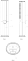
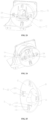
FIG. 1 shows a front view of an embodiment of an air conditioner indoor unit according to the present invention; -
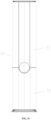
FIG. 2 shows a side view of an embodiment of the air conditioner indoor unit according to the present invention; -
FIG. 3 shows a top view of an embodiment of the air conditioner indoor unit according to the present invention; -
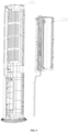
FIG. 4 shows an exploded view of an embodiment of the air conditioner indoor unit according to the present invention; -
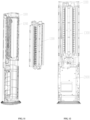
FIG. 5 shows a sectional view of the air conditioner indoor unit according to the present invention from a first visual angle; -
FIG. 6 shows a sectional view of the air conditioner indoor unit according to the present invention from a second visual angle; -
FIG. 7 shows a sectional view of the air conditioner indoor unit according to the present invention from a third visual angle; -
FIG. 8 shows an assembled view of an evaporator portion and an air intake panel portion of the air conditioner indoor unit according to the present invention; -
FIG. 9 shows an exploded view of the evaporator portion and the air intake panel portion of the air conditioner indoor unit according to the present invention; -
FIG. 10 shows an assembled view of air duct portions of the air conditioner indoor unit according to the present invention; -
FIG. 11 shows an exploded view of the air duct portions of the air conditioner indoor unit according to the present invention; -
FIG. 12 shows an assembled view of a fresh air device and an air outlet structure of the air conditioner indoor unit according to the present invention; -
FIG. 13 shows an exploded view of the fresh air device and the air outlet structure of the air conditioner indoor unit according to the present invention; -
FIG. 14 shows an assembled view of a front panel of the air conditioner indoor unit according to the present invention; -
FIG. 15 shows an exploded view of the front panel of the air conditioner indoor unit according to the present invention; -
FIG. 16 shows an assembled view of a lower panel of the air conditioner indoor unit according to the present invention; -
FIG. 17 shows an exploded view of the lower panel of the air conditioner indoor unit according to the present invention; -
FIG. 18 shows an exploded view of an embodiment of the air outlet structure according to the present invention; -
FIG. 19 shows a structural schematic diagram of a moving portion of the air outlet structure according to the present invention from one visual angle; -
FIG. 20 shows a structural schematic diagram of a moving member of a moving portion of an air outlet structure according to the present invention; -
FIG. 21 shows a structural schematic diagram of a moving portion of an air outlet structure according to the present invention from another visual angle; -
FIG. 22 shows an exploded view of another embodiment of the air outlet structure according to the present invention; -
FIG. 23 shows a structural schematic diagram of another embodiment of the air outlet structure according to the present invention from one visual angle; -
FIG. 24 shows a structural schematic diagram of another embodiment of the air outlet structure according to the present invention from another visual angle; -
FIG. 25 shows a structural schematic diagram of an air baffle member of the air outlet structure according to the present invention; -
FIG. 26 shows a front view of the air baffle member of the air outlet structure according to the present invention; -
FIG. 27 shows a side view of the air baffle member of the air outlet structure according to the present invention from one visual angle; -
FIG. 28 shows a side view of the air baffle member of the air outlet structure according to the present invention from another visual angle; -
FIG. 29 shows a structural schematic diagram of a covering member of the air outlet structure according to the present invention; -
FIG. 30 shows a front view of the covering member of the air outlet structure according to the present invention; -
FIG. 31 shows a side view of the covering member of the air outlet structure according to the present invention from one visual angle; -
FIG. 32 shows a side view of the covering member of the air outlet structure according to the present invention from another visual angle; -
FIG. 33 is a schematic view illustrating the covering member mounted on the air baffle member of the air outlet structure according to the present invention; and -
FIG. 34 is a schematic view illustrating the covering member being removed from the air baffle member of the air outlet structure according to the present invention. - Where, the above accompanying drawings include the following reference signs:
- 10. air baffle member; 12. air baffle body portion; 13. receiving portion; 20. covering member; 30. moving portion; 50. indoor unit panel; 51. front panel; 511. protrusion; 52. lower panel; 53. receiving hole; 60. air out duct housing; 61. air out duct; 70. air baffle portion;
- 1000. cooling and heating device; 1100. air intake panel portion; 1200. evaporator portion; 1300. air duct portion; 1400. air out frame portion; 1600. top cover;
- 2000. fresh air device; 2100. fresh air housing; 2200. fresh air passage; 2210. fresh air inlet; 2220. fresh air outlet; 2300. polluted air passage; 2310. polluted air inlet; 2320. polluted air outlet; 2400. heat exchange core; 2500. motor; 2600. fresh air blade; 2700. air exhaust blade; 2800. first filter screen; 2900. second filter screen;
- 31. support member; 311. first sliding groove; 312. rolling portion; 313. first stopper; 314. second sliding groove; 315. second stopper; 32. transmission assembly; 321. transmission gear; 322. transmission rack; 323. push rod; 324. retaining ring; 325. first screw; 326. washer; 33. moving member; 331. third receiving space; 333. first sliding portion; 3331. first sliding column; 334. fourth receiving space; 335. rolling groove; 336. first limiting block; 34. driving motor; 72. second mounting portion; 721. mounting rod; 722. support plate; 723. second sliding portion; 724. second limiting block;
- 11. second connection assembly; 111. first mounting portion; 1111. adjustable plate; 1112. first support portion; 1113. first mounting plate; 112. second mounting portion; 1121.second support portion; 1122. second mounting plate; 12.air baffle body portion; 13. receiving portion; 20. covering member; 21. first connection assembly; 211. first locking member; 2111. first connection portion; 2112. locking hook; 212. second locking member; 2121. second connection portion; 2122. stopper.
- It should be noted that embodiments of the present application and features in the embodiments may be combined with each other if there is no conflict with the scope of the invention as defined in the claims. Hereinafter, the present invention will be described in detail with reference to the accompanying drawings and in conjunction with the embodiments.
- Please refer to
FIG. 1 to 17 , the present invention provides an air conditioner indoor unit including afresh air device 2000. Thefresh air device 2000 has afresh air outlet 2220. The air conditioner indoor unit further includes anindoor unit panel 50 configured to shield an air outlet of the air conditioner indoor unit. Theindoor unit panel 50 has a receivinghole 53 which is in communication with thefresh air outlet 2220, and the receivinghole 53 is located at a side of thefresh air device 2000 proximate to the air outlet. - By means of providing the receiving
hole 53 at the side of thefresh air device 2000 proximate to the air outlet, the air conditioner indoor unit of the present invention enables fresh air to blow from the side proximate to the air outlet of the air conditioner indoor unit. Such an arrangement enables air exhaust of the air conditioner to blow fresh air from the fresh air outlet to different positions in the room, thereby avoiding a short circuit between the fresh air and polluted air, and enhancing fluidity of the fresh air. - The air conditioner indoor unit further includes an
air baffle portion 70. At least part of theair baffle portion 70 is disposed inside the receivinghole 53. Theair baffle portion 70 has a first position and a second position, and theair baffle portion 70 may be movably disposed between the first position and the second position, so that theair baffle portion 70 closes and blocks the receivinghole 53 when theair baffle portion 70 is located at the first position, and that theair baffle portion 70 is separated from the receivinghole 53 when theair baffle portion 70 is moved to the second position, thus thefresh air device 2000 may blow air through a gap between the receivinghole 53 and theair baffle portion 70. - The
air baffle portion 70 includes anair baffle member 10. Theair baffle member 10 is adjustably provided in the receivinghole 53. Theair baffle member 10 is closed and blocked in the receiving hole when theair baffle portion 70 is located at the first position. When theair baffle portion 70 is located at the second position, theair baffle member 10 is separated from theindoor unit panel 50. - In a specific implementation, as shown in
FIGS. 4 and6 , the receivinghole 53 includes a tapered hole section, and an outer wall surface of theair baffle member 10 matches an inner wall surface of the tapered hole section. Such an arrangement enables the fresh air to flow upward and forward, and the exhaust air of the air conditioner indoor unit may blow the fresh air to farther positions. - In the present embodiment, the
air baffle portion 70 includes a coveringmember 20. The coveringmember 20 is connected to theair baffle member 10 and located at a side of theair baffle member 10 away from thefresh air device 2000. The coveringmember 20 is provided over and covers theair baffle member 10, so as to shield theair baffle member 10. In this way, theair baffle member 10 and the coveringmember 20 constitute a relatively sealed space, thereby protecting a moving mechanism therein, further preventing dust and insects, and reducing noise of movement. Moreover, such an arrangement may prevent a child from possibly touching a moving portion, thereby improving safety. - In a specific implementation, the covering
member 20 has a disk structure, and an outer surface of the coveringmember 20 is flush with theindoor unit panel 50. Such an arrangement makes the air outlet structure more beautiful. - As shown in
FIGS. 4 ,13 and18 , the air conditioner indoor unit includes an air outduct housing 60. The outduct housing 60 is disposed inside theindoor unit panel 50, and has an air outduct 61. One end of the air outduct 61 communicates with thefresh air outlet 2220, and another end of the air outduct 61 communicates with the receiving hole, so that the fresh air enters the receiving hole through the air outduct 61. The fresh air is air generated by thefresh air device 2000. - According to the invention, as shown in
FIGS. 22 and25 , theair baffle member 10 includes an airbaffle body portion 12 and a receivingportion 13 connected to the airbaffle body portion 12. The receivingportion 13 is located at a side of the airbaffle body portion 12 proximate to thefresh air device 2000. The receivingportion 13 is disposed under the air outduct 61, and the airbaffle body portion 12 is disposed in front of the air outduct 61, so that the fresh air blows from a gap between the receivinghole 53 and the airbaffle body portion 12 through the air outduct 61 when theair baffle portion 70 is located at the second position. - In order to realize a movement of the
air baffle portion 70, as shown inFIG. 18 , the receivingportion 13 has a first receiving space. The air conditioner indoor unit includes a movingportion 30 connected to the air outduct housing 60, and at least part of the movingportion 30 is located inside the first receiving space. The movingportion 30 is in a transmission connection with theair baffle portion 70 to drive theair baffle portion 70 to move. - In a specific implementation, the first receiving space is provided with a moving portion mounting plate, and at least part of the moving
portion 30 is fixedly arranged on the moving portion mounting plate, so that the movingportion 30 drives theair baffle member 10 to move. - In a specific implementation, one end of the air out
duct 61 proximate to theair baffle portion 70 has a strip-shaped passage. - Preferably, the strip-shaped passage is arc-shaped. The strip-shaped passage has an arc-shaped curved surface, and the receiving
portion 13 has an outer wall surface matching the arc-shaped curved surface, so that the receivingportion 13 is located under the air outduct 61 when theair baffle portion 70 is located at the first position. - In a specific implementation, as shown in
FIGS. 1 to 2 ,4 ,16 to 17 , theindoor unit panel 50 includes afront panel 51 and alower panel 52 disposed under thefront panel 51. The receivinghole 53 is disposed in thefront panel 51. Thefront panel 51 has a first end and a second end opposite to each other. Thefront panel 51 has aprotrusion 511 protruding from the second end. At least part of the receiving hole is disposed in theprotrusion 511, and thelower panel 52 has a groove matching theprotrusion 511, so that thelower panel 52 is mounted on thefront panel 51. In a specific implementation, theprotrusion 511 has a mounting surface and a blocking surface connected to the mounting surface. An inner side surface of thelower plate 52 fits the mounting surface, and the groove abuts against the blocking surface. - In a specific implementation, the blocking surface is an arc-shaped curved surface, and the groove is an arc-shaped groove matching the blocking surface.
- In an embodiment, the air conditioner indoor unit further includes a cooling and
heating device 1000 located above thefresh air device 2000, and thefresh air outlet 2220 is provided at an upper end of thefresh air device 2000. - In an embodiment, the air conditioner indoor unit further includes an induction device for detecting air quality of indoor air. The air conditioner indoor unit further includes a light emitting device provided over the covering
member 20 and located within theair baffle portion 70. The light emitting device is in a signal communication with the induction device, to receive air quality information detected by the induction device, and display light of a corresponding color according to the air quality information so as to inform a user of air quality at this time. - In an embodiment, the
fresh air device 2000 further includes afresh air housing 2100 in which afresh air passage 2200 and apolluted air passage 2300 are provided. Afresh air inlet 2210 and afresh air outlet 2220 communicating with thefresh air passage 2200 and apolluted air inlet 2310 and apolluted air outlet 2320 communicating with thepolluted air passage 2300 are provided in thefresh air housing 2100. - In an embodiment, the
fresh air device 2000 further includes aheat exchange core 2400 provided in thefresh air housing 2100, and theheat exchange core 2400 communicates with both thefresh air passage 2200 and thepolluted air passage 2300 so that the fresh air in thefresh air passage 2200 and the polluted air in thepolluted air passage 2300 exchange heat in theheat exchange core 2400. By combining an ordinary air conditioner with a total heat exchange, the fresh air may be introduced to renew the indoor air, and the indoor polluted air is discharged to improve air quality. The fresh air and the polluted air may exchange energy through a total heat exchanger to recover energy, thereby reducing an energy loss. - The air conditioner indoor unit of the present invention mainly includes two portions, i.e. an upper portion and a lower portion. The upper portion is the cooling and
heating device 1000, and the lower portion is thefresh air device 2000. Assembly and disassembly of various parts of the air conditioner indoor unit are shown inFIGS. 8 to 17 . - In an embodiment, the cooling and
heating device 1000 includes an airintake panel portion 1100, anevaporator portion 1200, anair duct portion 1300, an air outframe portion 1400, and atop cover 1600. - In a specific implementation, as shown in
FIGS. 4 ,8-12 , the airintake panel portion 1100 includes an air inlet panel and an air inlet filter screen. - In a specific implementation, the
evaporator portion 1200 includes an evaporator, a side plate, an evaporator bracket, and a water receiving tray. - In a specific implementation, the
air duct portion 1300 includes an air duct, a cross-flow fan, an air out panel, a sweeping blade, an air passage driving motor, and an air passage driving gear. - In a specific implementation, the
evaporator portion 1200 is fixed to the airintake panel portion 1100 by upper, lower, left and right screws. - In a specific implementation, the
air duct portion 1300 is fixed to theevaporator portion 1200 and the airintake panel portion 1100 by snaps provided at left and right sides. - In an embodiment, as shown in
FIGS. 5 and 6 , thefresh air device 2000 further includes amotor 2500,fresh air blades 2600,air exhaust blades 2700, afirst filter screen 2800, and asecond filter screen 2900. - In an embodiment, in the fresh air device, the
motor 2500 drives thefresh air blades 2600 and theair exhaust blades 2700 to rotate, and indoor polluted air is discharged to the outdoors through thepolluted air passage 2300 and theheat exchange core 2400. Outdoor fresh air is introduced into the indoors through thefresh air passage 2200, thefirst filter screen 2800, theheat exchange core 2400, and thesecond filter screen 2900. The polluted air and the fresh air exchange sensible heat and latent heat in theheat exchange core 2400. - For example, in summer, an outdoor air temperature is higher than an indoor air temperature, and the fresh air passes through the
heat exchange core 2400, and part of energy is transferred to indoor polluted air and discharged from the indoors, thus achieving a cooling effect. - For example, in winter, an outdoor air temperature is lower than an indoor air temperature, and the fresh air absorbs part of energy from the polluted air through the
heat exchange core 2400 to achieve an effect of increasing temperature. - In this way, it can be realized that a temperature of introduced fresh air is not too high or too low, thus avoiding causing a serious increase of load or human body discomfort after introduction of the fresh air. What's more, the polluted air discharged transfers part of energy to the fresh air or absorbs part of energy from the fresh air, thereby avoiding an energy waste.
- In an embodiment, when the fresh air passes through the
first filter screen 2800 and thesecond filter screen 2900, a cleaning effect can be achieved, thereby improving quality of indoor air. The fresh air blows upward and forward through thefresh air outlet 2220, and may be brought to farther locations by air blowing from a fan of the cooling andheating device 1000, thereby preventing the short circuit between the fresh air and the polluted air. - In an embodiment, please refer to
FIGS. 18 to 24 , the air conditioner indoor unit includes an air outlet structure connected to thefresh air device 2000. The air outlet structure includes anair baffle portion 70, an air outduct housing 60, and a movingportion 30. - In an embodiment, as shown in
FIG. 18 , at least portion of the movingportion 30 is connected to theair baffle portion 70. The movingportion 30 moves in an extending direction of the receiving hole to drive theair baffle portion 70 to move between the first position and the second position, so as to close and block the receiving hole when theair baffle portion 70 moves to the first position, and separate theair baffle portion 70 from the receiving hole when theair baffle portion 70 moves to the second position, thereby allowing the air conditioner indoor unit to blow air through a gap between the receiving hole and theair baffle portion 70. By providing theair baffle portion 70 and the movingportion 30, and by arranging the movingportion 30 to move in the extending direction of the receiving hole, theair baffle portion 70 is driven to extend and contract. The movingportion 30 may drive theair baffle portion 70 to extend and contract conveniently and quickly. The air conditioner indoor unit has a simple structure, operates stably and reliably, and saves the cost, and the assembly efficiency thereof is higher. - Where, the moving
portion 30 enables theair baffle portion 70 to extend outward when the air conditioner indoor unit works, and enables theair baffle portion 70 to retract into theindoor unit panel 50, making the appearance aligned and beautiful when the air conditioner indoor unit stops working. - In an embodiment, the moving
portion 30 includes asupport member 31 connected to the air outduct housing 60, and theair baffle portion 70 is movably provided relative to thesupport member 31 and slidably connected to thesupport member 31 to support theair baffle portion 70. - In order to achieve extension and contraction of the
air baffle portion 70, the movingportion 30 according to the invention further includes atransmission assembly 32 which is in transmission connection with theair baffle portion 70, to drive theair baffle portion 70 to move. - As shown in
FIG. 19 , thetransmission assembly 32 includes atransmission gear 321 and atransmission rack 322 meshing with thetransmission gear 321. Thetransmission gear 321 is in transmission connection with thetransmission rack 322, and theair baffle portion 70 is connected with thetransmission rack 322, so that theair baffle portion 70 moves under the action of thetransmission gear 321 and thetransmission rack 322. Such an arrangement makes the air conditioner outdoor unit have a simple structure and operate stably and reliably, and to be installed conveniently, thereby saving the cost. - In an embodiment, as shown in
FIG. 18 , the movingportion 30 further includes asupport member 31 to which theair baffle portion 70 is slidably connected, and a movingmember 33. The movingmember 33 is slidably connected to the supportingmember 31 and positioned above the supportingmember 31. Thetransmission rack 322 is arranged on the movingmember 33, and theair baffle portion 70 is fixedly connected to the movingmember 33, so that theair baffle portion 70 moves under the drive of the movingportion 33. - In a specific implementation, as shown in
FIGS. 19-20 , the movingmember 33 has athird receiving space 331 in which thetransmission gear 321 is disposed, and thetransmission rack 322 is provided on an inner wall of thethird receiving space 331. - In order to drive the
transmission gear 321 to rotate, as shown inFIG. 18 , the movingportion 30 further includes a drivingmotor 34 fixedly connected to thesupport member 31, and the drivingmotor 34 is in a transmission connection with thetransmission gear 321, so that the drivingmotor 34 drives thetransmission gear 321 to rotate. - In a specific implementation, the driving
motor 34 is provided at a side of thesupport member 31 away from the movingmember 33, and thesupport member 31 has a through hole, so that the driving shaft of the drivingmotor 34 passes through the through hole and is connected to thetransmission gear 321. - In a specific implementation, a motor mounting portion of the driving
motor 34 is wrapped with a rubber washer and fixed to thesupport member 31 by screws, so as to effectively reduce noise caused by vibration of the drivingmotor 34. The motor mounting portion is a mounting corner bracket. - In a specific implementation, the driving shaft is installed and matches the
transmission gear 321 by means of cutting edges, and is locked by a retainingring 324 to prevent thetransmission gear 321 from falling off. - In an embodiment, the
support member 31 has a first slidinggroove 311, and the movingmember 33 has a first slidingportion 333 matching the first slidinggroove 311. At least part of the first slidingportion 333 is slidably provided within the first slidinggroove 311. Such an arrangement of the first slidinggroove 311 can guide movement of the movingmember 33 and prevent the movingmember 33 from moving up and down. - In a specific implementation, as shown in
FIG. 19 , the movingmember 33 includes a moving member body portion. The first slidingportion 333 is connected with the moving member body portion. The moving member body portion has a first end and a second end arranged opposite to each other. Two first slidingportions 333 are provided. One first slidingportion 333 is disposed at the first end of the moving member body portion, and another first slidingportion 333 is disposed at the second end of the moving member body portion. There are two first slidinggrooves 311, and the two first slidinggrooves 333 are arranged to be in one-to-one correspondence with the two first slidinggrooves 311, and each first slidingportion 333 is slidably arranged in a corresponding first slidinggroove 311. - In a specific implementation, as shown in
FIG. 20 , the first slidingportion 333 has a plurality of first slidingcolumns 3331. The plurality of first slidingcolumns 3331 are provided and spaced apart in an extension direction of the first slidingportion 333. Each first slidingcolumn 3331 extends in a width direction of the first slidingportion 333, and each first slidingcolumn 3331 protrudes from an end surface of the first slidingportion 333 away from the moving member body portion, so that the first slidingportion 333 is in contact with a groove bottom of the first slidinggroove 311 by means of the first slidingcolumns 3331. - In a specific implementation, outer surfaces of at least part of the first sliding
columns 3331 which protrude from the end surface of the first slidingportion 333 away from the moving member main body portion are spherical crown surfaces. Such an arrangement can reduce frictional resistance between the movingmember 33 and the first slidinggroove 311. - In a specific implementation, at least part of the first sliding
columns 3331 which protrude from the end surface of the first slidingportion 333 away from the moving member body portion each are at least part of a spherical structure. - Preferably, at least part of the first sliding
columns 3331 which protrude from the end surface of the first slidingportion 333 away from the moving member body portion each are hemispherical. In a specific implementation, the first slidingcolumns 3331 each protrude from two side walls of the first slidingportion 333, so that the two side walls of the first slidingportion 333 are in contact with groove walls of the first slidinggrooves 311 by means of the first slidingcolumns 3331. Such an arrangement can reduce frictional resistance between the movingmember 33 and the first slidinggroove 311. - In an embodiment, one groove wall of the first sliding
groove 311 is positioned over the first slidingportion 333 to stop the first slidingportion 333, thereby preventing the first slidingportion 333 from jumping up and down. - In an embodiment, as shown in
FIG. 18 , a rollingportion 312 is disposed on thesupport member 31, and the movingmember 33 has afourth receiving space 334 in which the rollingportion 312 is disposed. A rollinggroove 335 matching the rollingportion 312 is disposed on an inner wall of thefourth receiving space 334, and the rollingportion 312 is rotatably arranged in the rollinggroove 335. The arrangement of the rollingportion 312 may assist the movingmember 33 to move, and may also restrict displacement of the movingmember 33 in a direction perpendicular to the movement direction. - Preferably, the rolling
portion 312 is a roller. - In a specific implementation, there are two rolling
grooves 335, and the two rollinggrooves 335 are arranged opposite to each other at both sides of the rollingportion 312. The rollinggroove 335 is configured to cooperate with the rollingportion 312 to restrict a displacement of the movingmember 312 in a direction perpendicular to the movement direction. The rollingportion 312 is in rolling contact with the movingmember 33 when the movingmember 33 moves forward and backward, thereby effectively reducing frictional resistance during a movement of the movingmember 33. - In a specific implementation, a vertical column stands on the
support member 31 for mounting the rollingportion 312. The rollingportion 312 is mounted to the vertical column by afirst screw 325. In a specific implementation, a washer 326 is provided between thefirst screw 325 and the rollingportion 312 so that the rollingportion 312 smoothly rolls. - In order to limit a final position of the moving member when the moving
member 33 is pushed out, as shown inFIG. 21 , the movingmember 33 has a first limitingblock 336, and thesupport member 31 is provided with afirst stopper 313. Thefirst stopper 313 is disposed at an end of thesupport member 31 proximate to theair baffle portion 70, so as to stop the first limitingblock 336. In another embodiment, as shown inFIG. 22 , thetransmission assembly 32 includes apush rod 323. At least part of thepush rod 323 moves in an extension direction of the receiving hole, and an end of thepush rod 323 is connected to theair baffle portion 70, so that thepush rod 323 drives theair baffle portion 70 to move. - Preferably, the
push rod 323 is an electric push rod. The electric push rod is an electric telescopic machine. An end of the electric push rod is mounted on the air outduct housing 60 by screws, and a telescopic rod at another end of the electric push rod is electrically driven to extend and retract. The telescopic rod is hinged to a mounting rod 721 of theair baffle portion 70, so as to drive theair baffle portion 70 to move. - In a specific implementation, as shown in
FIG. 23 , the movingportion 30 includes thesupport member 31. Theair baffle portion 70 is provided with a second mounting portion 72 including the mounting rod 721 and two support plates 722. One end of the mounting rod 721 is connected to one support plate 722, and another end of the mounting rod 721 is connected to another support plate 722. Thepush rod 323 is connected to the mounting rod 721. Theair baffle portion 70 is slidably connected to thesupport member 31 by two support plates 722. - In a specific implementation, as shown in
FIG. 24 , thesupport member 31 has a second slidinggroove 314. Each support plate 722 has a second slidingportion 723 matching the second slidinggroove 314. There are two second slidinggrooves 314. The two second slidingportions 723 are arranged to be in one-to-one correspondence with the two second slidinggrooves 314. A least part of each second slidingportion 723 is slidably arranged in a corresponding second slidinggroove 314. The second slidinggrooves 314 functions as a guide. - In an embodiment, one groove wall of the second sliding
groove 314 is disposed over the second slidingportion 723 to stop the second slidingportion 723, thereby preventing the second slidingportion 723 from jumping up and down. - In order to limit a final position of the
air baffle portion 70 when theair baffle portion 70 is pushed out, at least one support plate 722 is provided with a second limiting block 724. Thesupport member 31 is provided with asecond stopper 315, and thesecond stopper 315 is disposed at an end of thesupport member 31 proximate to theair baffle portion 70, so as to stop the second limiting block 724. - In an embodiment, the electric push rod is a telescopic mechanism. Compared with a gear and rack pushing mechanism, the electric push rod has a simpler structure and has higher assembly efficiency.
- In an embodiment, please refer to
FIGS. 25 to 34 , in a specific implementation, the coveringmember 20 has an operation-waiting position and an installation position. The coveringmember 20 is detachably disposed on theair baffle member 10, so that the coveringmember 20 and theair baffle member 10 are positioned when the coveringmember 20 is at the operation-waiting position, and that the coveringmember 20 is fixedly connected with theair baffle member 10 when the coveringmember 20 is at the installation position. During the installation of the coveringmember 20, the coveringmember 20 is moved from the operation-waiting position to the installation position, to complete the installation of the coveringmember 20. When the coveringmember 20 is removed, the coveringmember 20 is moved from the installation position to the operation-waiting position, so as to complete removal of the coveringmember 20. - In order to realize a connection between the
air baffle member 10 and the coveringmember 20, as shown inFIGS. 25 and29 , a side of the coveringmember 20 proximate to theair baffle member 10 is provided with a first connectingassembly 21. Theair baffle member 10 includes the airbaffle body portion 12. A side of the airbaffle body portion 12 proximate to the coveringmember 20 is provided with a second connecting assembly 11 matching the first connectingassembly 21. The first connectingassembly 21 is connected to the second connecting assembly 11 so that the coveringmember 20 is connected to theair baffle member 10 by means of the first connectingassembly 21 and the second connecting assembly 11. Such an arrangement makes the assembly structure have smooth inner and outer sides, and not easy to deform and more beautiful in structure. In a specific implementation, the second connecting assembly 11 includes a first mountingportion 111, and the first connectingassembly 21 includes afirst locking member 211 that matches the first mountingportion 111. When the coveringmember 20 is located at the installation position, thefirst locking member 211 is locked in the first mountingportion 111. The first mountingportion 111 is adjustably arranged on the airbaffle body portion 12, so that the airbaffle body portion 12 is locked in or separated from the first mountingportion 111 by adjusting the first mountingportion 111. - Preferably, the first mounting
portion 111 is located at a lower side of the first receiving space. - In a specific implementation, an adjustable gap is defined in the air
baffle body portion 12, and the adjustable gap surrounds anadjusting plate 1111. By pushing theadjusting plate 1111, the first mountingportion 111 is forced to move, so as to separate the airbaffle body portion 12 from the first mountingportion 111. In this way, disassembly by means of pressing the adjusting plate 1111is convenient, simple and highly efficient. - Where, in the process of locking the
first locking member 211 in the first mountingportion 111, the coveringmember 20 moves from the operation-waiting position to the installation position, and when the first mountingportion 111 is pressed to move toward the coveringmember 20, the first mountingportion 111 is separated from thefirst locking member 211, so that the coveringmember 20 moves from the installation position to the operation-waiting position. - In a specific implementation, the adjustable gap includes a plurality of split slots each extending from one end surface of the air
baffle body portion 12 to another end surface. - In a specific implementation, a plurality of split slots penetrate through the air baffle
main body 12. - In a specific implementation, the plurality of split slots includes a first split slot, a second split slot, and a third split slot. The first split slot is arranged in parallel with the second split slot. One end of the third split slot communicates with one end of the first split slot, and another end of the third split slot communicates with one end of the second split slot, so as to enclose the
adjusting plate 1111 as a rectangular plate. - In a specific implementation, the
first locking member 211 has a first connection portion 2111 and a locking hook 2112 vertically connected to the first connection portion 2111. The first mountingportion 111 includes afirst support portion 1112 and a first mounting plate 1113 connected to thefirst support portion 1112. Thefirst support portion 1112 is connected to theadjusting plate 1111. The first mounting plate 1113 has a first through hole, so that the locking hook 2112 is locked in the first through hole when the coveringmember 20 is located at the installation position. Where, the locking hook 2112 is located at a side of the first mounting plate 1113 proximate to the fresh air passage when the coveringmember 20 is located at the operation-waiting position, and the locking hook 2112 is locked in the first through hole when the coveringmember 20 is located at the installation position. - In an embodiment, the second connecting member 11 includes a plurality of second mounting
portions 112. The plurality of second mountingportions 112 are provided and spaced apart around the center of the airbaffle body portion 12. The first connectingassembly 21 includes a plurality ofsecond locking members 212. The plurality ofsecond locking members 212 are arranged to be in a one-to-one correspondence with the plurality of second mountingportions 112. Eachsecond locking member 212 is locked in a corresponding second mountingportion 112. - Preferably, there are three second mounting
portions 112. One second mounting portion 112is located at an upper side of the first receiving space and is opposite to the first mountingportion 111, and other two second mountingportions 112 are provided oppositely at left and right sides of the first receiving space. - In a specific implementation, the
second locking member 212 has a second connecting portion 2121 and astopper 2122 vertically connected to the second connecting portion 2121. Thesecond mounting portion 112 has asecond support portion 1121 and asecond mounting plate 1122 connected to thesecond support portion 1121. Thesecond support portion 1121 is connected to theair baffle member 10. Thesecond mounting plate 1122 is provided with a second through hole. At least portion of thestopper 2122 passes through the second through hole and is locked to the second mountingportion 112. During the installation of the coveringmember 20, it is highly efficient to assembly the coveringmember 20 by means of pushing and sliding the coveringmember 20 down. - In a specific implementation, the
air baffle member 10 and thecover 20 are made of plastic material. Such an arrangement is less cost. - From the above description, it can be seen that the above embodiments of the present invention achieve the following technical effects.
- In the air conditioner indoor unit of the present invention, the receiving
hole 53 is disposed at the side of thefresh air device 2000 proximate to the air outlet, thereby enabling the fresh air to blow at the side proximate to the air outlet of the air conditioned indoor unit. Such an arrangement enables the exhaust air of the air conditioner to blow fresh air at the fresh air outlet to different positions in a room, thereby avoiding the short circuit between the fresh air with and the polluted air, and enhancing fluidity of the fresh air.
Claims (10)
- An air conditioner indoor unit comprising a fresh air device (2000), the fresh air device (2000) having a fresh air outlet (2220), whereinthe air conditioner indoor unit further comprises an indoor unit panel (50) configured to shield an air outlet of the air conditioner indoor unit; the indoor unit panel has a receiving hole (53); the receiving hole (53) communicates with the fresh air outlet (2220); and the receiving hole (53) is located at a side of the fresh air device (2000) proximate to the air outlet;the air conditioning indoor unit further comprises an air baffle portion (70);at least part of the air baffle portion (70) is disposed inside the receiving hole (53); the air baffle portion (70) has a first position and a second position; the air baffle portion (70) is movably disposed between the first position and the second position; the air baffle portion (70) closes and blocks the receiving hole (53) when the air baffle portion (70) is located at the first position; the air baffle portion (70) is separated from the receiving hole (53) when the air baffle portion (70) is moved to the second position to allow the fresh air device (2000) to blow air through a gap between the receiving hole (53) and the air baffle portion (70); characterized in that the air baffle portion (70) comprises an air baffle member (10);the air baffle member (10) is adjustably disposed in the receiving hole (53); the air baffle member (10) closes and blocks the receiving hole (53) when the air baffle portion (70) is located at the first position; and the air baffle member (10) is separated from the indoor unit panel (50) when the air baffle portion (70) is located at the second position;the air conditioner indoor unit comprises an air out duct housing (60);the air out duct housing (60) is disposed inside the indoor unit panel (50), and has an air out duct (61); one end of the air out duct (61) communicates with the fresh air outlet (2220); and another end of the air out duct (61) communicates with the receiving hole (53) to allow fresh air to enter the receiving hole (53) through the air out duct (61);the air baffle member (10) comprises an air baffle body portion (12) and a receiving portion (13) connected to the air baffle body portion (12); the receiving portion (13) is located at a side of the air baffle body portion (12) proximate to the fresh air device (2000); the receiving portion (13) is disposed under the air out duct (61); and the air baffle body portion (12) is disposed in front of the air out duct (61), and the fresh air blows from a gap between the receiving hole (53) and the air baffle body portion (12) through the air out duct (61) when the air baffle portion (70) is located at the second position;the receiving portion (13) has a first receiving space; the air conditioner indoor unit comprises a moving part (30);the moving portion (30) is connected to the air out duct housing (60); at least part of the moving portion (30) is located inside the first receiving space; and the moving portion (30) is in a transmission connection with the air baffle portion (70) to drive the air baffle portion (70) to move;the moving portion (30) comprises a support member (31) connected to the air out duct housing (60), and the air baffle portion (70) is movably provided relative to the support member (31) and slidably connected to the support member (31) to support the air baffle portion (70);the moving portion (30) further comprises a transmission assembly (32) which is in transmission connection with the air baffle portion (70);the transmission assembly (32) comprises a transmission gear (321) and a transmission rack (322) meshing with the transmission gear (321); the transmission gear (321) is in transmission connection with the transmission rack (322); and the air baffle portion (70) is connected with the transmission rack (322).
- The air conditioner indoor unit according to claim 1, characterized in that the receiving hole (53) comprises a tapered hole section, and an outer wall surface of the air baffle member (10) matches an inner wall surface of the tapered hole section.
- The air conditioner indoor unit according to claim 1, characterized in that the air baffle portion (70) comprises a covering member (20);
the covering member (20) is connected to the air baffle member (10) and located at a side of the air baffle member (10) away from the fresh air device (2000); and the covering member (20) is provided over and covers the air baffle member (10) to shield the air baffle member (10). - The air conditioner indoor unit according to claim 3, characterized in that the covering member (20) has a disk structure, and an outer surface of the covering member (20) is flush with the indoor unit panel (50).
- The air conditioning indoor unit according to claim 1, characterized in that an end of the air out duct (61) proximate to the air baffle portion (70) has a strip-shaped passage.
- The air conditioner indoor unit according to claim 5, characterized in that the strip-shaped passage is arc-shaped; the strip-shaped passage has an arc-shaped curved surface; and the receiving portion (13) has an outer wall surface matching the arc-shaped curved surface, and the receiving portion (13) is located under the air out duct (61) when the air baffle portion (70) is located at the first position.
- The air conditioner indoor unit according to claim 1, characterized in that the indoor unit panel (50) comprises a front panel (51) and a lower panel (52) disposed under the front panel (51);
the receiving hole (53) is disposed in the front panel (51); the front panel (51) has a first end and a second end opposite to each other; the front panel (51) has a protrusion (511) protruding from the second end; at least part of the receiving hole (53) is disposed in the protrusion (511); and the lower panel (52) has a groove matching the protrusion (511) to enable the lower panel (52) to be mounted on the front panel (51). - The air conditioner indoor unit according to claim 7, characterized in that the protrusion (511) has a mounting surface and a blocking surface connected to the mounting surface; an inner side surface of the lower panel (52) fits the mounting surface; the groove abuts the blocking surface; and
the blocking surface is an arc-shaped curved surface, and the groove is an arc-shaped groove matching the blocking surface. - The air conditioner indoor unit according to claim 1, characterized in that the air conditioner indoor unit further comprises a cooling and heating device (1000);
the cooling and heating device (1000) is located above the fresh air device (2000); and the fresh air outlet (2220) is provided at an upper end of the fresh air device (2000). - The air conditioner indoor unit according to claim 3, characterized in that the air conditioner indoor unit further comprises:an induction device, configured to detect an air quality of indoor air; anda light emitting device, provided on the covering member (20) and located within the air baffle portion (70);the light emitting device is in a signal communication with the induction device to receive air quality information detected by the induction device and display light of a corresponding color according to the air quality information.
Applications Claiming Priority (2)
| Application Number | Priority Date | Filing Date | Title |
|---|---|---|---|
| CN201811320755.4A CN111156595A (en) | 2018-11-07 | 2018-11-07 | Indoor unit of air conditioner |
| PCT/CN2018/125033 WO2020093570A1 (en) | 2018-11-07 | 2018-12-28 | Air conditioner indoor unit |
Publications (3)
| Publication Number | Publication Date |
|---|---|
| EP3835677A1 EP3835677A1 (en) | 2021-06-16 |
| EP3835677A4 EP3835677A4 (en) | 2021-10-20 |
| EP3835677B1 true EP3835677B1 (en) | 2023-09-13 |
Family
ID=70555399
Family Applications (1)
| Application Number | Title | Priority Date | Filing Date |
|---|---|---|---|
| EP18939464.6A Active EP3835677B1 (en) | 2018-11-07 | 2018-12-28 | Air conditioner indoor unit |
Country Status (3)
| Country | Link |
|---|---|
| EP (1) | EP3835677B1 (en) |
| CN (1) | CN111156595A (en) |
| WO (1) | WO2020093570A1 (en) |
Families Citing this family (2)
| Publication number | Priority date | Publication date | Assignee | Title |
|---|---|---|---|---|
| TWI789825B (en) * | 2021-07-13 | 2023-01-11 | 魏榮宗 | Air Conditioning System |
| CN115479311A (en) * | 2022-09-20 | 2022-12-16 | 青岛海尔空调器有限总公司 | Fresh air device, air conditioner and air conditioner |
Family Cites Families (10)
| Publication number | Priority date | Publication date | Assignee | Title |
|---|---|---|---|---|
| JP2002130730A (en) * | 2000-10-30 | 2002-05-09 | Kazutaro Oyabu | Improvement of lower outlet and upper inlet type air conditioner |
| CN105371370B (en) * | 2015-11-19 | 2019-01-25 | 珠海格力电器股份有限公司 | The air-out component of indoor unit and air conditioner with it |
| CN105485774A (en) * | 2016-01-22 | 2016-04-13 | 广东美的制冷设备有限公司 | Indoor unit of floor air conditioner |
| CN105757950B (en) * | 2016-04-19 | 2018-11-13 | 奥克斯空调股份有限公司 | A kind of air conditioner |
| CN106196358A (en) * | 2016-08-17 | 2016-12-07 | 张忠 | Fresh air conditioner all-in-one |
| CN107676870A (en) * | 2017-08-18 | 2018-02-09 | 广东美的制冷设备有限公司 | Vertical air-conditioner indoor unit and there is its air conditioner |
| CN107525169A (en) * | 2017-09-25 | 2017-12-29 | 广东美的制冷设备有限公司 | Air treatment module and air conditioner |
| CN207962866U (en) * | 2018-01-30 | 2018-10-12 | 广东美的制冷设备有限公司 | Cabinet air-conditioner and air conditioner with it |
| CN108679713A (en) * | 2018-05-21 | 2018-10-19 | 青岛海尔空调器有限总公司 | Air conditioner indoor unit and its control method |
| CN209026956U (en) * | 2018-11-07 | 2019-06-25 | 珠海格力电器股份有限公司 | Air conditioner indoor unit |
-
2018
- 2018-11-07 CN CN201811320755.4A patent/CN111156595A/en active Pending
- 2018-12-28 WO PCT/CN2018/125033 patent/WO2020093570A1/en unknown
- 2018-12-28 EP EP18939464.6A patent/EP3835677B1/en active Active
Also Published As
| Publication number | Publication date |
|---|---|
| WO2020093570A1 (en) | 2020-05-14 |
| EP3835677A4 (en) | 2021-10-20 |
| EP3835677A1 (en) | 2021-06-16 |
| CN111156595A (en) | 2020-05-15 |
Similar Documents
| Publication | Publication Date | Title |
|---|---|---|
| CN100383464C (en) | Ventilating system | |
| CN107477675B (en) | Indoor unit of vertical air conditioner and air conditioner with indoor unit | |
| KR101781845B1 (en) | Indoor unit of air conditioner | |
| EP3835677B1 (en) | Air conditioner indoor unit | |
| CN103175279A (en) | Curtain wall forced ventilator | |
| CN100547306C (en) | Package AC plant and header board thereof | |
| CN210463144U (en) | Smoke exhaust ventilator | |
| WO2020181655A1 (en) | Multi-mode ventilation purifier | |
| CN201034424Y (en) | Low-power consumption air heat exchanger | |
| CN101545652A (en) | Bidirectional smoke insulation and heat insulation cooling device | |
| CN209042600U (en) | Electric depurant, vertical air-conditioner indoor unit and air conditioner | |
| CN104807209A (en) | Solar heating fresh air ventilator | |
| KR20070094052A (en) | Indoor unit for air conditioner | |
| CN209026956U (en) | Air conditioner indoor unit | |
| CN209068679U (en) | A kind of fresh air system | |
| CN213421361U (en) | Antifog haze purifies air conditioning unit | |
| CN110906461B (en) | Window type sensible heat exchange fresh air fan | |
| CN210485895U (en) | Novel fresh air conditioner with filter screen for purifying and adjusting fresh air and return air volume | |
| CN110578967A (en) | indoor unit of air conditioner | |
| CN218820930U (en) | Air guide assembly of air conditioner | |
| CN220669596U (en) | Air duct machine | |
| CN2524146Y (en) | Separate bidirectional indoor unit of air conditioner | |
| CN215808891U (en) | Air supply structure of air conditioner in purifying room | |
| CN218763676U (en) | Fan coil for central air conditioner | |
| CN219108088U (en) | Automatic temperature control double-cold-source fan coil for cabinet |
Legal Events
| Date | Code | Title | Description |
|---|---|---|---|
| STAA | Information on the status of an ep patent application or granted ep patent |
Free format text: STATUS: THE INTERNATIONAL PUBLICATION HAS BEEN MADE |
|
| PUAI | Public reference made under article 153(3) epc to a published international application that has entered the european phase |
Free format text: ORIGINAL CODE: 0009012 |
|
| STAA | Information on the status of an ep patent application or granted ep patent |
Free format text: STATUS: REQUEST FOR EXAMINATION WAS MADE |
|
| 17P | Request for examination filed |
Effective date: 20210311 |
|
| AK | Designated contracting states |
Kind code of ref document: A1 Designated state(s): AL AT BE BG CH CY CZ DE DK EE ES FI FR GB GR HR HU IE IS IT LI LT LU LV MC MK MT NL NO PL PT RO RS SE SI SK SM TR |
|
| A4 | Supplementary search report drawn up and despatched |
Effective date: 20210917 |
|
| RIC1 | Information provided on ipc code assigned before grant |
Ipc: F24F 13/10 20060101ALI20210914BHEP Ipc: F24F 7/00 20210101ALI20210914BHEP Ipc: F24F 1/0035 20190101AFI20210914BHEP |
|
| DAV | Request for validation of the european patent (deleted) | ||
| DAX | Request for extension of the european patent (deleted) | ||
| GRAP | Despatch of communication of intention to grant a patent |
Free format text: ORIGINAL CODE: EPIDOSNIGR1 |
|
| RIC1 | Information provided on ipc code assigned before grant |
Ipc: F24F 13/10 20060101ALI20230328BHEP Ipc: F24F 7/00 20210101ALI20230328BHEP Ipc: F24F 1/0035 20190101AFI20230328BHEP |
|
| STAA | Information on the status of an ep patent application or granted ep patent |
Free format text: STATUS: GRANT OF PATENT IS INTENDED |
|
| INTG | Intention to grant announced |
Effective date: 20230504 |
|
| P01 | Opt-out of the competence of the unified patent court (upc) registered |
Effective date: 20230530 |
|
| GRAS | Grant fee paid |
Free format text: ORIGINAL CODE: EPIDOSNIGR3 |
|
| GRAA | (expected) grant |
Free format text: ORIGINAL CODE: 0009210 |
|
| STAA | Information on the status of an ep patent application or granted ep patent |
Free format text: STATUS: THE PATENT HAS BEEN GRANTED |
|
| AK | Designated contracting states |
Kind code of ref document: B1 Designated state(s): AL AT BE BG CH CY CZ DE DK EE ES FI FR GB GR HR HU IE IS IT LI LT LU LV MC MK MT NL NO PL PT RO RS SE SI SK SM TR |
|
| REG | Reference to a national code |
Ref country code: CH Ref legal event code: EP |
|
| REG | Reference to a national code |
Ref country code: DE Ref legal event code: R096 Ref document number: 602018057769 Country of ref document: DE |
|
| REG | Reference to a national code |
Ref country code: IE Ref legal event code: FG4D |
|
| REG | Reference to a national code |
Ref country code: LT Ref legal event code: MG9D |
|
| REG | Reference to a national code |
Ref country code: NL Ref legal event code: MP Effective date: 20230913 |
|
| PG25 | Lapsed in a contracting state [announced via postgrant information from national office to epo] |
Ref country code: GR Free format text: LAPSE BECAUSE OF FAILURE TO SUBMIT A TRANSLATION OF THE DESCRIPTION OR TO PAY THE FEE WITHIN THE PRESCRIBED TIME-LIMIT Effective date: 20231214 |
|
| PG25 | Lapsed in a contracting state [announced via postgrant information from national office to epo] |
Ref country code: SE Free format text: LAPSE BECAUSE OF FAILURE TO SUBMIT A TRANSLATION OF THE DESCRIPTION OR TO PAY THE FEE WITHIN THE PRESCRIBED TIME-LIMIT Effective date: 20230913 Ref country code: RS Free format text: LAPSE BECAUSE OF FAILURE TO SUBMIT A TRANSLATION OF THE DESCRIPTION OR TO PAY THE FEE WITHIN THE PRESCRIBED TIME-LIMIT Effective date: 20230913 Ref country code: NO Free format text: LAPSE BECAUSE OF FAILURE TO SUBMIT A TRANSLATION OF THE DESCRIPTION OR TO PAY THE FEE WITHIN THE PRESCRIBED TIME-LIMIT Effective date: 20231213 Ref country code: LV Free format text: LAPSE BECAUSE OF FAILURE TO SUBMIT A TRANSLATION OF THE DESCRIPTION OR TO PAY THE FEE WITHIN THE PRESCRIBED TIME-LIMIT Effective date: 20230913 Ref country code: LT Free format text: LAPSE BECAUSE OF FAILURE TO SUBMIT A TRANSLATION OF THE DESCRIPTION OR TO PAY THE FEE WITHIN THE PRESCRIBED TIME-LIMIT Effective date: 20230913 Ref country code: HR Free format text: LAPSE BECAUSE OF FAILURE TO SUBMIT A TRANSLATION OF THE DESCRIPTION OR TO PAY THE FEE WITHIN THE PRESCRIBED TIME-LIMIT Effective date: 20230913 Ref country code: GR Free format text: LAPSE BECAUSE OF FAILURE TO SUBMIT A TRANSLATION OF THE DESCRIPTION OR TO PAY THE FEE WITHIN THE PRESCRIBED TIME-LIMIT Effective date: 20231214 Ref country code: FI Free format text: LAPSE BECAUSE OF FAILURE TO SUBMIT A TRANSLATION OF THE DESCRIPTION OR TO PAY THE FEE WITHIN THE PRESCRIBED TIME-LIMIT Effective date: 20230913 |
|
| PGFP | Annual fee paid to national office [announced via postgrant information from national office to epo] |
Ref country code: DE Payment date: 20231214 Year of fee payment: 6 |
|
| REG | Reference to a national code |
Ref country code: AT Ref legal event code: MK05 Ref document number: 1611644 Country of ref document: AT Kind code of ref document: T Effective date: 20230913 |
|
| PG25 | Lapsed in a contracting state [announced via postgrant information from national office to epo] |
Ref country code: NL Free format text: LAPSE BECAUSE OF FAILURE TO SUBMIT A TRANSLATION OF THE DESCRIPTION OR TO PAY THE FEE WITHIN THE PRESCRIBED TIME-LIMIT Effective date: 20230913 |
|
| PG25 | Lapsed in a contracting state [announced via postgrant information from national office to epo] |
Ref country code: IS Free format text: LAPSE BECAUSE OF FAILURE TO SUBMIT A TRANSLATION OF THE DESCRIPTION OR TO PAY THE FEE WITHIN THE PRESCRIBED TIME-LIMIT Effective date: 20240113 |