EP3835172B1 - Caster brake device - Google Patents
Caster brake device Download PDFInfo
- Publication number
- EP3835172B1 EP3835172B1 EP20804421.4A EP20804421A EP3835172B1 EP 3835172 B1 EP3835172 B1 EP 3835172B1 EP 20804421 A EP20804421 A EP 20804421A EP 3835172 B1 EP3835172 B1 EP 3835172B1
- Authority
- EP
- European Patent Office
- Prior art keywords
- cable
- lever
- caster
- roller
- brake device
- Prior art date
- Legal status (The legal status is an assumption and is not a legal conclusion. Google has not performed a legal analysis and makes no representation as to the accuracy of the status listed.)
- Active
Links
Images


Classifications
-
- B—PERFORMING OPERATIONS; TRANSPORTING
- B60—VEHICLES IN GENERAL
- B60B—VEHICLE WHEELS; CASTORS; AXLES FOR WHEELS OR CASTORS; INCREASING WHEEL ADHESION
- B60B33/00—Castors in general ; Anti-clogging castors
- B60B33/0078—Castors in general ; Anti-clogging castors characterised by details of the wheel braking mechanism
- B60B33/0086—Castors in general ; Anti-clogging castors characterised by details of the wheel braking mechanism acting on rim or side portion of tyre
-
- B—PERFORMING OPERATIONS; TRANSPORTING
- B60—VEHICLES IN GENERAL
- B60B—VEHICLE WHEELS; CASTORS; AXLES FOR WHEELS OR CASTORS; INCREASING WHEEL ADHESION
- B60B33/00—Castors in general ; Anti-clogging castors
- B60B33/0078—Castors in general ; Anti-clogging castors characterised by details of the wheel braking mechanism
- B60B33/0092—Castors in general ; Anti-clogging castors characterised by details of the wheel braking mechanism actuated remotely, e.g. by cable or electrically
-
- B—PERFORMING OPERATIONS; TRANSPORTING
- B62—LAND VEHICLES FOR TRAVELLING OTHERWISE THAN ON RAILS
- B62B—HAND-PROPELLED VEHICLES, e.g. HAND CARTS OR PERAMBULATORS; SLEDGES
- B62B5/00—Accessories or details specially adapted for hand carts
- B62B5/04—Braking mechanisms; Locking devices against movement
- B62B5/0404—Braking mechanisms; Locking devices against movement automatic
- B62B5/0414—Braking mechanisms; Locking devices against movement automatic dead man's brakes
-
- B—PERFORMING OPERATIONS; TRANSPORTING
- B60—VEHICLES IN GENERAL
- B60B—VEHICLE WHEELS; CASTORS; AXLES FOR WHEELS OR CASTORS; INCREASING WHEEL ADHESION
- B60B2200/00—Type of product being used or applied
- B60B2200/40—Articles of daily use
- B60B2200/43—Carts
-
- B—PERFORMING OPERATIONS; TRANSPORTING
- B60—VEHICLES IN GENERAL
- B60B—VEHICLE WHEELS; CASTORS; AXLES FOR WHEELS OR CASTORS; INCREASING WHEEL ADHESION
- B60B2900/00—Purpose of invention
- B60B2900/30—Increase in
- B60B2900/331—Safety or security
- B60B2900/3312—Safety or security during regular use
-
- B—PERFORMING OPERATIONS; TRANSPORTING
- B62—LAND VEHICLES FOR TRAVELLING OTHERWISE THAN ON RAILS
- B62B—HAND-PROPELLED VEHICLES, e.g. HAND CARTS OR PERAMBULATORS; SLEDGES
- B62B2301/00—Wheel arrangements; Steering; Stability; Wheel suspension
- B62B2301/04—Wheel arrangements; Steering; Stability; Wheel suspension comprising a wheel pivotable about a substantially vertical axis, e.g. swivelling castors
- B62B2301/044—Wheel arrangements; Steering; Stability; Wheel suspension comprising a wheel pivotable about a substantially vertical axis, e.g. swivelling castors arranged remote from the longitudinal centreline of the hand propelled vehicle
-
- B—PERFORMING OPERATIONS; TRANSPORTING
- B62—LAND VEHICLES FOR TRAVELLING OTHERWISE THAN ON RAILS
- B62B—HAND-PROPELLED VEHICLES, e.g. HAND CARTS OR PERAMBULATORS; SLEDGES
- B62B3/00—Hand carts having more than one axis carrying transport wheels; Steering devices therefor; Equipment therefor
- B62B3/002—Hand carts having more than one axis carrying transport wheels; Steering devices therefor; Equipment therefor characterised by a rectangular shape, involving sidewalls or racks
-
- B—PERFORMING OPERATIONS; TRANSPORTING
- B62—LAND VEHICLES FOR TRAVELLING OTHERWISE THAN ON RAILS
- B62B—HAND-PROPELLED VEHICLES, e.g. HAND CARTS OR PERAMBULATORS; SLEDGES
- B62B5/00—Accessories or details specially adapted for hand carts
- B62B5/04—Braking mechanisms; Locking devices against movement
- B62B5/0438—Braking mechanisms; Locking devices against movement hand operated
-
- B—PERFORMING OPERATIONS; TRANSPORTING
- B62—LAND VEHICLES FOR TRAVELLING OTHERWISE THAN ON RAILS
- B62B—HAND-PROPELLED VEHICLES, e.g. HAND CARTS OR PERAMBULATORS; SLEDGES
- B62B5/00—Accessories or details specially adapted for hand carts
- B62B5/04—Braking mechanisms; Locking devices against movement
- B62B5/0457—Braking mechanisms; Locking devices against movement by locking in a braking position
- B62B5/0461—Braking mechanisms; Locking devices against movement by locking in a braking position with positive engagement
Definitions
- the present invention relates to a brake device for a caster.
- a brake device for a caster in which a brake shoe is disposed at a frame (fork), and an operation body is inserted and fitted in a hole drilled in the top panel of a frame, and the operation body is operated synchronously via a transfer means constituted of a cam, a link rod, and the like connected to a brake operation lever.
- IT FE20 130 006 A1 discloses a braking device for shopping trolleys and everything that is handled manually using means that use wheels with fixed or swivel support, wherein the braking device has means of a lever for a braking trolley.
- the braking device is u-shaped, wherein the final part has one or more protruding tooth, which could be lowered to contact one or more wheel locking tooth causing total blocking of the wheel.
- the wheel locking tooth has an inclined surface at an acute angle with respect to a line connecting an outer circumferential end of the wheel locking tooth and a center of the wheel is formed at an end face of the wheel locking tooth that comes in contact with the protruding tooth.
- DE 195 17 729 A1 discloses a manually movable transport carriage suitable for transport on moving walkways and escalators, comprising a pushing device and the braking device being connected to each other via brake linkages, wherein the rear wheels having stop surfaces and the braking device having projections intended to engage the stop surfaces, wherein, when the braking device is not actuated, reverse rotation of the rear wheels is prevented and forward rotation is possible against the action of the braking force applied by the braking device.
- a stop surface is arranged towards the horizontal axis, i.e. radially.
- the projection is spring-loaded.
- US 6 817 451 B1 discloses a brake system for running stroller comprising a synchronizer to enable the brake system simultaneously braking to rear wheels with one hand lever and an arrester device to arrest the wheel to completely stop the roller, wherein the hand lever affects a first steel wire from the synchronizer which affects a pair of second steel wires, wherein the steel wires are secured within a disk which is movably disposed within synchronizer.
- the arrester device has an arrester ring with a plurality of radial arrester plaster spacedly formed on the arrester ring, wherein a check rod is insertable into a gap between the arrester a plates to hinder the wheels from rotation via a tread plate.
- the brake shoe is brought into contact with the circumferential surface of a roller so that the roller is braked by frictional resistance caused by the contact. For this reason, the braking effect may be reduced, and the circumferential surface of the roller may be damaged.
- the present invention was completed in view of the problem in the background art. It is an object of the present invention to provide a brake device for a caster, which has a simple structure, provides reliable braking, has no risk of damaging the circumferential surface of a roller, and has high durability.
- a brake device for a caster comprises a plurality of projecting parts formed concentrically on opposite side-surfaces of a roller, and levers set across the roller at opposite side-panels of a fork so as to be opposed to the projecting parts, and a claw formed at a tip of each of the levers so as to be opposed to each of the projecting parts.
- the levers are operated, so that the claw is engaged with a concave part formed between the projecting parts, to lock the rotation of the roller, wherein a cable coupling unit having a slide body is set at an intermediate point of a cable, and the cable on an operation lever side and the cable on the lever side are coupled via the slide body, wherein the cable coupling unit comprises at least one compression spring, wherein at least one tension spring is operatively interposed between the cable and the slide body and/or the cable and the lever.
- the claw of the lever is engaged with the projecting part formed at the side-surface of the roller, thereby applying brake to the roller. Accordingly, a reliable braking effect can be obtained, and the circumferential surface of the roller will not be damaged.
- the brake device for a caster in accordance with the present invention in addition to the effect, when release cannot be performed with ease due to biting of the claw of the lever into the concave part between the projecting parts, or the like, the at least one interposed tension spring is stretched, which reduces the burden on the cable. In addition, also subsequently, the spring is urged on the lever in the direction of release, which performs the action of releasing the brake.
- a plurality of the cables of the operation levers are coupled with the slide body, and a plurality of cables to the levers of the casters are coupled with the slide body.
- the claw of the lever is engaged with the inclined surface of the projecting part, and hence the engagement becomes firm, resulting in further enhancement of the braking effect.
- the brake device for a caster may in addition to the effect, even when the roller rotates, the cable will not be twisted.
- Fig. 1 shows a basket trolley 1.
- the basket trolley 1 has a rectangular bottom panel 2.
- a fence 3 is vertically arranged in the periphery of the bottom panel 2.
- One side of the fence 3 includes double doors 3a.
- Casters 4 are set at the four corners of the bottom panel 2. Out of these, two casters are rotatable casters 4a, and the residual two casters are fixed casters 4b.
- each rotatable caster 4a includes a fork 5 in a generally U shape including a top panel 5a and side-panels 5b bent in a direction at right angles from the opposite ends thereof.
- a shaft 6 is laid across both the side-panels 5b, 5b of the fork 5 in an inserted manner, and a roller 7 is rotatably held by the shaft 6.
- a mount stand 8 is fixedly set as shown in Fig. 2 .
- the top panel 5a of the fork 5 is rotatably set at the mount stand 8 via a bearing not shown.
- the basket trolley 1 includes a brake device 10 of the rotatable caster 4a set therein.
- the brake device 10 includes a brake part 11 set at the rotatable caster 4a, an operation part 12 set at a column 3b situated diagonally with respect to the fence 3 in the embodiment shown, and a power transfer means 13 for coupling the brake part 11 and the operation part 12.
- the brake part 11 includes a frame 14.
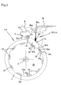
- the frame 14 includes a tubular coupling tube 15, and levers 16 projecting in a direction at right angles from the opposite ends thereof in the embodiment illustrated in Fig. 3 .
- Each lever 16 includes a claw 16a at the tip thereof.
- the frame 14 is rotatably held by fitting the tubular coupling tube 15 to a shaft 5c set across the side-panels 5b, 5b of the fork 5.
- the frame 14 is arranged so that the levers 16 sandwich the roller 7 as shown in Fig. 3 .
- a rod 17 for hanging a spring (or a direct cable) described later thereon is set across both the levers 16.
- a plurality of projecting parts 19 are formed at disks (the opposite side panels of the wheel) 18 on the opposite side-surfaces of the roller 7.
- the projecting parts 19 are arranged at regular intervals in the circumferential direction concentrically with the disk 18.
- an inclined surface 19a making an acute angle with the outer circumferential surface is formed at the end of each projecting part 19.
- a bracket 20 is set at the column 3b of the fence 3 as shown in Fig. 4 .
- An operation lever 21 is rotatably set at the bracket 20.
- a tongue piece 21a for holding a cable described later is protrusively provided at the base of the operation lever 21.
- the power transfer means 13 includes a cable coupling unit 22 set at the side surface of the fence 3.
- the cable coupling unit 22 includes a slide body 24 in a case 23 in the embodiment shown in Fig. 5 .
- the slide body 24 is for coupling an operation part side cable 25 and a brake part side cable 26.
- an outer tube 25a of the cable 25 is engaged with one end of the case 23, and an outer tube 26a of the cable 26 is engaged with the other end of the case 23.
- an inner cable 25b of the cable 25 is engaged with one end of the slide body 24 by a screw 27, and an inner cable 26b of the cable 26 is engaged with the other end of the slide body 24 via a spring 28.
- the slide body 24 is urged to the brake part side (downward of Fig. 5 ) by a spring 29 fitted loosely to the inner cable 25b of the cable 25.
- the cable 25 is guided upward from the operation part 12 along the column 3b, and crawls on the upper end and the side surface of the fence 3 to be guided to the cable coupling unit 22.
- the cable 26 crawls on the side surface of the fence 3 to be guided to the caster 4a, and is guided to the fork 5 through the rotation axis of the mount stand 8 as shown in Fig. 2 .
- the outer tube 26a of the cable 26 is engaged with the top panel 5a, and the inner cable 26b is rotatably coupled to the end of a spring 30 using a swivel mechanism. Then, the other end of the spring 30 is engaged with the rod 17 of the lever 16.
- the spring 30 provided at the brake part 11 is not necessarily required. It may be configured such that the inner cable 26b of the cable 26 is directly coupled to the rod 17 of the lever 16. Conversely, when the spring 30 is provided at the brake part 11, for the cable coupling unit 22, it may be configured such that the inner cable 26b of the cable 26 is directly engaged with the other end of the slide body 24 without the spring 28 interposed therebetween.
- the opposite side end of the cable 25 is engaged with the tongue piece 21a of the operation lever 21 at the operation part 12 as shown in Fig. 4 .
- the inclined surface 19a is formed at the projecting part 19, and the claw 16a of the lever 16 is caused to bite into the inclined surface 19a. Accordingly, the claw 16a is engaged with the projecting part 19 with reliability.
- the angle of the inclined surface 19a namely, the angle made between the line connecting the outer circumferential end of the projecting part 19 and the center of the roller 7 and the inclined surface is large, the engagement between the claw 16a of the lever 16 and the projecting part 19 becomes more firm.
- the angle is preferably about 30 to 50 degrees.
- the end of the inner cable 26b and the lever 16 are coupled via the stretching spring 30.
- a T-shaped flat spring 31 is disposed by being laid across the levers 16.
- a hole 32 is formed at the tip 31a, and one end of the inner cable 26b is rotatably coupled to the hole using a swivel mechanism or the like.
- a torsion coil spring 33 is disposed by being laid across the levers 16, and a hole 33a is formed at the center of the torsion coil spring 33.
- One end of the inner cable 26b is rotatably coupled with the hole 33a using a swivel mechanism, or the like.
- the lever 16 is engaged with the projecting part 19 projecting toward the side of the roller 7 from above as shown in Fig. 3 .
- the projecting part 19 is formed at the inner circumferential surface of the wheel 34 of the roller 7 in such a manner as to project in the direction of the shaft 6, so that the lever 16 is engaged with the projecting part 19 from below.
- the members and the parts performing the same actions as those in the embodiment are given the same reference numerals and signs in Fig. 8 , and the description thereon is omitted.
- the configuration of the cable coupling unit 22 is configured such that the inner cable 26b of the brake part side cable 26 is engaged with the other end of the slide body 24 via the spring 28.
- the spring 30 is provided at the brake part 11, as shown in Fig. 9 , for the cable coupling unit 22, it may be configured such that the inner cable 26b of the cable 26 is directly engaged, by a screw 35, with the other end of the slide body 24 without the spring 28 interposed therebetween.
- the brake device for a caster in accordance with the present invention is widely applicable as a brake device for a caster for use in, for example, in addition to a flat trolley except for a basket trolley, and a folding trolley, a wheelchair, a stretcher, a baby buggy, a wagon, a bed, a copying machine, an IV stand, a compressor, a spot cooler, a power generator, or a welding machine.
Landscapes
- Engineering & Computer Science (AREA)
- Mechanical Engineering (AREA)
- Chemical & Material Sciences (AREA)
- Combustion & Propulsion (AREA)
- Transportation (AREA)
- Braking Arrangements (AREA)
- Handcart (AREA)
Description
- The present invention relates to a brake device for a caster.
- As disclosed in PTL 1, a brake device for a caster is available, in which a brake shoe is disposed at a frame (fork), and an operation body is inserted and fitted in a hole drilled in the top panel of a frame, and the operation body is operated synchronously via a transfer means constituted of a cam, a link rod, and the like connected to a brake operation lever.
- Further,
IT FE20 130 006 A1 -
DE 195 17 729 A1 discloses a manually movable transport carriage suitable for transport on moving walkways and escalators, comprising a pushing device and the braking device being connected to each other via brake linkages, wherein the rear wheels having stop surfaces and the braking device having projections intended to engage the stop surfaces, wherein, when the braking device is not actuated, reverse rotation of the rear wheels is prevented and forward rotation is possible against the action of the braking force applied by the braking device. Further, a stop surface is arranged towards the horizontal axis, i.e. radially. In addition, the projection is spring-loaded. -
US 6 817 451 B1 discloses a brake system for running stroller comprising a synchronizer to enable the brake system simultaneously braking to rear wheels with one hand lever and an arrester device to arrest the wheel to completely stop the roller, wherein the hand lever affects a first steel wire from the synchronizer which affects a pair of second steel wires, wherein the steel wires are secured within a disk which is movably disposed within synchronizer. The arrester device has an arrester ring with a plurality of radial arrester plaster spacedly formed on the arrester ring, wherein a check rod is insertable into a gap between the arrester a plates to hinder the wheels from rotation via a tread plate. - [PTL 1]
Japanese Patent Application Publication No. 2008-302903 - Incidentally, in the brake device disclosed in PTL 1, the brake shoe is brought into contact with the circumferential surface of a roller so that the roller is braked by frictional resistance caused by the contact. For this reason, the braking effect may be reduced, and the circumferential surface of the roller may be damaged.
- The present invention was completed in view of the problem in the background art. It is an object of the present invention to provide a brake device for a caster, which has a simple structure, provides reliable braking, has no risk of damaging the circumferential surface of a roller, and has high durability.
- According to the present invention, a brake device for a caster comprises a plurality of projecting parts formed concentrically on opposite side-surfaces of a roller, and levers set across the roller at opposite side-panels of a fork so as to be opposed to the projecting parts, and a claw formed at a tip of each of the levers so as to be opposed to each of the projecting parts.
- According to the invention, the levers are operated, so that the claw is engaged with a concave part formed between the projecting parts, to lock the rotation of the roller, wherein a cable coupling unit having a slide body is set at an intermediate point of a cable, and the cable on an operation lever side and the cable on the lever side are coupled via the slide body, wherein the cable coupling unit comprises at least one compression spring, wherein at least one tension spring is operatively interposed between the cable and the slide body and/or the cable and the lever.
- With the brake device for a caster in accordance with the present invention, the claw of the lever is engaged with the projecting part formed at the side-surface of the roller, thereby applying brake to the roller. Accordingly, a reliable braking effect can be obtained, and the circumferential surface of the roller will not be damaged. With the brake device for a caster in accordance with the present invention, in addition to the effect, when release cannot be performed with ease due to biting of the claw of the lever into the concave part between the projecting parts, or the like, the at least one interposed tension spring is stretched, which reduces the burden on the cable. In addition, also subsequently, the spring is urged on the lever in the direction of release, which performs the action of releasing the brake. With the brake device for a caster in accordance with the present invention, in addition to the effect, a plurality of the cables of the operation levers are coupled with the slide body, and a plurality of cables to the levers of the casters are coupled with the slide body. As a result, it is possible to transfer the power of the selected operation lever to each caster.
- For this reason, the durability is also high, and further the structure is simple.
- With the brake device for a caster preferably in addition to the effect, the claw of the lever is engaged with the inclined surface of the projecting part, and hence the engagement becomes firm, resulting in further enhancement of the braking effect.
- With the brake device for a caster may in addition to the effect, even when the roller rotates, the cable will not be twisted.
-
- [
Fig. 1 ]
Fig. 1 is a perspective view showing one embodiment of a trolley mounting a brake device for a caster in accordance with the present invention thereon. - [
Fig. 2 ]
Fig. 2 is a conceptual longitudinal cross sectional view of a caster showing the essential part of the brake device for a caster in accordance with the present invention, and shows a brake operating state. - [
Fig. 3 ]
Fig. 3 is a conceptual partial perspective view of a caster showing the essential part of the brake device for a caster in accordance with the present invention, and shows a brake release state. - [
Fig. 4 ]
Fig. 4 is a conceptual cross sectional view showing an operation part of the brake device for a caster in accordance with the present invention. - [
Fig. 5 ]
Fig. 5 is a conceptual cross sectional view showing a cable coupling unit of the brake device for a caster in accordance with the present invention. - [
Fig. 6 ]
Fig. 6 is a conceptual longitudinal cross sectional view of a caster showing the essential part of the brake device for a caster in accordance with the present invention, and shows a brake release state. - [
Fig. 7 ]
Fig. 7 is a conceptual perspective view showing a modified example of a lever of the brake device for a caster in accordance with the present invention. - [
Fig. 8 ]
Fig. 8 is a conceptual longitudinal cross sectional view of a caster showing a modified example of the essential part of the brake device for a caster in accordance with the present invention, and (a) is a view showing a brake operation state, and (b) is a view showing a brake release state. - [
Fig. 9 ]
Fig. 9 is a conceptual cross sectional view showing a modified example of a cable coupling unit of the brake device for a caster in accordance with the present invention. - Below, a brake device for a caster in accordance with the present invention will be described in details by way of embodiments shown in the accompanying drawings.
-
Fig. 1 shows a basket trolley 1. The basket trolley 1 has arectangular bottom panel 2. Then, afence 3 is vertically arranged in the periphery of thebottom panel 2. One side of thefence 3 includesdouble doors 3a. -
Casters 4 are set at the four corners of thebottom panel 2. Out of these, two casters arerotatable casters 4a, and the residual two casters are fixed casters 4b. As shown inFig. 2 , eachrotatable caster 4a includes afork 5 in a generally U shape including atop panel 5a and side-panels 5b bent in a direction at right angles from the opposite ends thereof. Ashaft 6 is laid across both the side-panels fork 5 in an inserted manner, and aroller 7 is rotatably held by theshaft 6. At the lower surface of thebottom panel 2 of the basket trolley 1, amount stand 8 is fixedly set as shown inFig. 2 . Thetop panel 5a of thefork 5 is rotatably set at themount stand 8 via a bearing not shown. - The basket trolley 1 includes a
brake device 10 of therotatable caster 4a set therein. As shown inFig. 1 , thebrake device 10 includes abrake part 11 set at therotatable caster 4a, anoperation part 12 set at acolumn 3b situated diagonally with respect to thefence 3 in the embodiment shown, and a power transfer means 13 for coupling thebrake part 11 and theoperation part 12. - The
brake part 11 includes aframe 14. Theframe 14 includes atubular coupling tube 15, and levers 16 projecting in a direction at right angles from the opposite ends thereof in the embodiment illustrated inFig. 3 . Eachlever 16 includes aclaw 16a at the tip thereof. Then, theframe 14 is rotatably held by fitting thetubular coupling tube 15 to ashaft 5c set across the side-panels fork 5. Then, theframe 14 is arranged so that thelevers 16 sandwich theroller 7 as shown inFig. 3 . Further, arod 17 for hanging a spring (or a direct cable) described later thereon is set across both thelevers 16. - Whereas, at the
brake part 11, a plurality of projectingparts 19 are formed at disks (the opposite side panels of the wheel) 18 on the opposite side-surfaces of theroller 7. The projectingparts 19 are arranged at regular intervals in the circumferential direction concentrically with thedisk 18. Then, aninclined surface 19a making an acute angle with the outer circumferential surface is formed at the end of each projectingpart 19. - At the
operation part 12, abracket 20 is set at thecolumn 3b of thefence 3 as shown inFig. 4 . Anoperation lever 21 is rotatably set at thebracket 20. Atongue piece 21a for holding a cable described later is protrusively provided at the base of theoperation lever 21. - The power transfer means 13 includes a
cable coupling unit 22 set at the side surface of thefence 3. Thecable coupling unit 22 includes aslide body 24 in acase 23 in the embodiment shown inFig. 5 . Theslide body 24 is for coupling an operationpart side cable 25 and a brakepart side cable 26. With thecable coupling unit 22, anouter tube 25a of thecable 25 is engaged with one end of thecase 23, and anouter tube 26a of thecable 26 is engaged with the other end of thecase 23. Then, aninner cable 25b of thecable 25 is engaged with one end of theslide body 24 by ascrew 27, and aninner cable 26b of thecable 26 is engaged with the other end of theslide body 24 via aspring 28. - Further, with the
cable coupling unit 22, theslide body 24 is urged to the brake part side (downward ofFig. 5 ) by aspring 29 fitted loosely to theinner cable 25b of thecable 25. Incidentally, as shown inFig. 1 , thecable 25 is guided upward from theoperation part 12 along thecolumn 3b, and crawls on the upper end and the side surface of thefence 3 to be guided to thecable coupling unit 22. Whereas, thecable 26 crawls on the side surface of thefence 3 to be guided to thecaster 4a, and is guided to thefork 5 through the rotation axis of themount stand 8 as shown inFig. 2 . Theouter tube 26a of thecable 26 is engaged with thetop panel 5a, and theinner cable 26b is rotatably coupled to the end of aspring 30 using a swivel mechanism. Then, the other end of thespring 30 is engaged with therod 17 of thelever 16. - Incidentally, when the
spring 28 is provided at thecable coupling unit 22, thespring 30 provided at thebrake part 11 is not necessarily required. It may be configured such that theinner cable 26b of thecable 26 is directly coupled to therod 17 of thelever 16. Conversely, when thespring 30 is provided at thebrake part 11, for thecable coupling unit 22, it may be configured such that theinner cable 26b of thecable 26 is directly engaged with the other end of theslide body 24 without thespring 28 interposed therebetween. - The opposite side end of the
cable 25 is engaged with thetongue piece 21a of theoperation lever 21 at theoperation part 12 as shown inFig. 4 . - With the
brake device 10 of therotatable caster 4a of the embodiment, in the normal state, namely, at the position at which theoperation lever 21 is not operated as indicated with a solid line, theslide body 24 of thecable coupling unit 22 is moved toward the brake part (downward ofFig. 5 ) by the urging force of thespring 29. As a result, theinner cable 26b of thecable 26 is relaxed as shown inFig. 2 , so that thelever 16 moves downward by its own weight, and further, thespring spring lever 16 is held downward, so that theclaw 16a of thelever 16 is fitted into theconcave part 19b between the projectingparts 19. In this state, theroller 7 is locked against the rotation in the forward direction (also in the backward direction) of the trolley 1. On the other hand, for the rotation in the counterclockwise direction of theroller 7, thetip wall 16b of thelever 16 comes in touch with theend face 19c of the adjacent projectingpart 19, thereby hindering the rotation. - When the
operation lever 21 is operated in the direction of thecolumn 3b (the direction indicated with a two-dot chain line ofFig. 4 ), theinner cable 25b of thecable 25 is lowered. As a result, theslide body 24 of thecable coupling unit 22 is pulled in the direction of the operation part (upward ofFig. 5 ) against the urging force of thespring 29. Then, thelever 16 is rotated upward inFig. 2 via theinner cable 26b of thecable 26 connected to theslide body 24. Accordingly, theclaw 16a is separated from the projectingpart 19 provided in addition on theroller 7. Therefore, the rotation of theroller 7 becomes free, and the trolley 1 can be run in the desirable direction. - At this step, namely, in order to separate the
claw 16a of thelever 16 from the projectingpart 19, it is necessary to rotate theroller 7 slightly anti-rotationally (in the counterclockwise direction inFig. 2 ). Meanwhile, the lifting force of thecable 26 acts on thelever 16. Thespring 28 interposed at an intermediate point of the cable, or thespring 30 interposed between the cable and the lever is stretched. As a result, the burden on the cable or the damage of the lever can be prevented. In addition, the stretchedspring lever 16 in the release direction (in this case, thespring - Incidentally, with the brake device for the embodiment, the
inclined surface 19a is formed at the projectingpart 19, and theclaw 16a of thelever 16 is caused to bite into theinclined surface 19a. Accordingly, theclaw 16a is engaged with the projectingpart 19 with reliability. When the angle of theinclined surface 19a, namely, the angle made between the line connecting the outer circumferential end of the projectingpart 19 and the center of theroller 7 and the inclined surface is large, the engagement between theclaw 16a of thelever 16 and the projectingpart 19 becomes more firm. However, when the locking of theroller 7 is released, it becomes difficult to separate theclaw 16a from the projectingpart 19. Therefore, in view of these, the angle is preferably about 30 to 50 degrees. - Further, in the embodiment, as shown in
Fig. 2 , the end of theinner cable 26b and thelever 16 are coupled via the stretchingspring 30. However, the following is also acceptable. As shown inFIG. 7(a) , a T-shapedflat spring 31 is disposed by being laid across thelevers 16. A hole 32 is formed at the tip 31a, and one end of theinner cable 26b is rotatably coupled to the hole using a swivel mechanism or the like. The following is also acceptable. As shown inFig. 7(b) , atorsion coil spring 33 is disposed by being laid across thelevers 16, and a hole 33a is formed at the center of thetorsion coil spring 33. One end of theinner cable 26b is rotatably coupled with the hole 33a using a swivel mechanism, or the like. - Further, in the embodiment, it is configured such that the
lever 16 is engaged with the projectingpart 19 projecting toward the side of theroller 7 from above as shown inFig. 3 . However, the following configuration is also acceptable. As shown inFig. 8 , the projectingpart 19 is formed at the inner circumferential surface of thewheel 34 of theroller 7 in such a manner as to project in the direction of theshaft 6, so that thelever 16 is engaged with the projectingpart 19 from below. Incidentally, the members and the parts performing the same actions as those in the embodiment are given the same reference numerals and signs inFig. 8 , and the description thereon is omitted. - Further, in the embodiment, as shown in
Fig. 5 , the configuration of thecable coupling unit 22 is configured such that theinner cable 26b of the brakepart side cable 26 is engaged with the other end of theslide body 24 via thespring 28. However, when thespring 30 is provided at thebrake part 11, as shown inFig. 9 , for thecable coupling unit 22, it may be configured such that theinner cable 26b of thecable 26 is directly engaged, by ascrew 35, with the other end of theslide body 24 without thespring 28 interposed therebetween. - Up to this point, a description has been given to the embodiments of the brake device for the rotatable caster in accordance with the present invention. However, it is naturally understood that the present invention is not limited to the embodiments at all, and may be variously modified or changed within the scope of the appended claims.
- For example, in the embodiment, a description has been given by taking the basket trolley 1 as an example. However, the brake device for a caster in accordance with the present invention is widely applicable as a brake device for a caster for use in, for example, in addition to a flat trolley except for a basket trolley, and a folding trolley, a wheelchair, a stretcher, a baby buggy, a wagon, a bed, a copying machine, an IV stand, a compressor, a spot cooler, a power generator, or a welding machine.
-
- 1
- Trolley
- 2
- Bottom panel
- 3
- Fence
- 3a
- Door
- 3b
- Column
- 4
- Caster
- 4a
- Rotatable caster
- 4b
- Fixed caster
- 5
- Fork
- 5a
- Top panel
- 5b
- Side-panel
- 5c
- Shaft
- 6
- Shaft
- 7
- Roller
- 8
- Mount stand
- 10
- Brake device
- 11
- Brake part
- 12
- Operation part
- 13
- Power transfer means
- 14
- Frame
- 15
- Coupling tube
- 16
- Lever
- 16a
- Claw
- 16b
- Tip wall
- 17
- Rod
- 18
- Disk (side-panel of wheel)
- 19
- Projecting part
- 19a
- Inclined surface
- 19b
- Concave part
- 19c
- End face
- 20
- Bracket
- 21
- Operation lever
- 21a
- Tongue piece
- 22
- Cable coupling unit
- 23
- Case
- 24
- Slide body
- 25
- Operation part side cable
- 25a
- Outer tube
- 25b
- Inner cable
- 26
- Brake part side cable
- 26a
- Outer tube
- 26b
- Inner cable
- 27
- Screw
- 28
- Spring
- 29
- Spring
- 30
- Spring
- 31
- Flat spring
- 31a
- Tip
- 32
- Hole
- 33
- Torsion coil spring
- 33a
- Hole
- 34
- Wheel
- 35
- Screw
Claims (3)
- A brake device (10) for a caster (4, 4a) comprising: a plurality of projecting parts (19) formed concentrically on opposite side-surfaces of a roller (7), and levers (16) set across the roller (7) at opposite side-panels (5b) of a fork (5) so as to be opposed to the projecting parts (19), and a claw (16a) formed at a tip of each of the levers (16) so as to be opposed to each of the projecting parts (19), wherein the levers (16) are operated, so that the claw (16a) is engaged with a concave part (19b) formed between the projecting parts (19), to lock the rotation of the roller (7), characterized in that a cable coupling unit (22) having a slide body (24) is set at an intermediate point of a cable (25, 26), and the cable (25) on an operation lever (21) side and the cable (26) on the lever (16) side are coupled via the slide body (24), wherein the cable coupling unit (22) comprises at least one compression spring (29), wherein at least one tension spring (28, 30, 31, 33) is operatively interposed between the cable (26) and the slide body (24) and/or the cable (26) and the lever (16).
- The brake device (10) for a caster (4, 4a) according to claim 1, wherein an inclined surface (19a) inclined at an acute angle of 30 to 50 degree with respect to a line connecting an outer circumferential end of the projecting part (19) and a center of the roller is formed at an end face of the projecting part (19) that comes in contact with the claw (16a) of the lever (16).
- The brake device (10) for a caster (4, 4a) according to claim 1 or 2, wherein the lever (16) is operated by a cable (25 ,26) coupled to an operation lever (21), and the cable (25, 26) is rotatably coupled to the lever (16).
Applications Claiming Priority (2)
| Application Number | Priority Date | Filing Date | Title |
|---|---|---|---|
| JP2019189454A JP7431010B2 (en) | 2019-10-16 | 2019-10-16 | caster brake device |
| PCT/JP2020/020551 WO2021075079A1 (en) | 2019-10-16 | 2020-05-25 | Caster brake device |
Publications (4)
| Publication Number | Publication Date |
|---|---|
| EP3835172A1 EP3835172A1 (en) | 2021-06-16 |
| EP3835172A4 EP3835172A4 (en) | 2022-01-12 |
| EP3835172B1 true EP3835172B1 (en) | 2025-04-23 |
| EP3835172C0 EP3835172C0 (en) | 2025-04-23 |
Family
ID=75486027
Family Applications (1)
| Application Number | Title | Priority Date | Filing Date |
|---|---|---|---|
| EP20804421.4A Active EP3835172B1 (en) | 2019-10-16 | 2020-05-25 | Caster brake device |
Country Status (10)
| Country | Link |
|---|---|
| US (1) | US11904634B2 (en) |
| EP (1) | EP3835172B1 (en) |
| JP (1) | JP7431010B2 (en) |
| KR (1) | KR102602397B1 (en) |
| CN (1) | CN112996711A (en) |
| ES (1) | ES3031795T3 (en) |
| HU (1) | HUE071960T2 (en) |
| PL (1) | PL3835172T3 (en) |
| TW (1) | TWI865619B (en) |
| WO (1) | WO2021075079A1 (en) |
Families Citing this family (4)
| Publication number | Priority date | Publication date | Assignee | Title |
|---|---|---|---|---|
| GB2611065B (en) * | 2021-09-24 | 2025-06-18 | Armorgard Holdings Ltd | Trolley Apparatus |
| US12415558B1 (en) * | 2022-12-12 | 2025-09-16 | Amazon Technologies, Inc. | Containers having lever-based actuation of brakes and locks |
| JP7828115B1 (en) * | 2025-02-20 | 2026-03-11 | 株式会社日乃本錠前 | Caster device with locking mechanism |
| KR102904518B1 (en) * | 2025-06-10 | 2025-12-26 | 주식회사 티디에스디스플레이 | Brake device for wheelchair treadmill |
Family Cites Families (23)
| Publication number | Priority date | Publication date | Assignee | Title |
|---|---|---|---|---|
| DE2105547A1 (en) * | 1971-02-06 | 1972-08-10 | Tente Rollen GmbH & Co, 5678 Wermelskirchen Tente | Swivel castor, especially for shopping carts in self-service shops |
| US4248445A (en) * | 1979-06-18 | 1981-02-03 | Vassar Hervey P | Caster brake and swivel lock |
| DE9412429U1 (en) * | 1994-08-02 | 1994-09-29 | Wanzl Gmbh & Co. Entwicklungs-Kg, 89340 Leipheim | Suitable trolleys for moving on moving walks and escalators |
| JPH11240305A (en) * | 1998-02-23 | 1999-09-07 | Kawajun Kk | Caster with brake |
| AUPP695398A0 (en) * | 1998-11-05 | 1998-12-03 | Rubber Auto Supplies Pty. Ltd. | Brake apparatus for a shopping trolley |
| FR2850933B1 (en) * | 2003-02-12 | 2005-04-15 | Ampafrance | STROLLER WITH LOCKING CONTROL MEANS AND BRAKE DELEGATION SEPARATED AND PLACED IN THE NEIGHBORHOOD OF OTHERS |
| US6817451B1 (en) * | 2003-04-02 | 2004-11-16 | Hung-Tsun Chen | Brake system for a running stroller |
| JP5187614B2 (en) | 2007-06-11 | 2013-04-24 | ハンマーキャスター株式会社 | caster |
| CA2725756A1 (en) * | 2008-06-24 | 2009-12-30 | Yazaki Kako Corporation | Brake-equipped caster |
| JP5294461B2 (en) * | 2008-12-16 | 2013-09-18 | トーヨーベンディング株式会社 | Wire cable branching device used for wheel brake mechanism |
| JP2013049406A (en) * | 2011-08-02 | 2013-03-14 | Hotta Kk | Swivel caster brake mechanism |
| ITFE20130006A1 (en) * | 2013-06-27 | 2014-12-28 | Sergio Toschi | MANUAL BRAKING DEVICE FOR WHEELS WITH ROTATING OR FIXED SUPPORT FOR EXPENSE TROLLEYS AND EVERYTHING THAT IS MANUALLY MOVED ON WHEELS |
| EP3103653B1 (en) * | 2014-02-07 | 2019-10-09 | Nansin Co. Ltd. | Double-lock caster |
| JP2016199130A (en) * | 2015-04-09 | 2016-12-01 | 株式会社日乃本錠前 | Double-wheel caster brake gear |
| KR101573235B1 (en) * | 2015-07-03 | 2015-12-02 | 최예진 | Baby wagon with improved ease of use |
| JP2017039405A (en) * | 2015-08-20 | 2017-02-23 | 平 武次 | caster |
| DE102016113069A1 (en) * | 2016-07-15 | 2018-01-18 | Tente Gmbh & Co. Kg | Swivel castor with an impeller |
| JP6854512B2 (en) * | 2017-04-04 | 2021-04-07 | 有限会社広島ピーエス | Brake unit |
| CN207045062U (en) * | 2017-06-21 | 2018-02-27 | 中山市维唐五金制品有限公司 | Embedded brake trundle |
| DE102017121146A1 (en) * | 2017-09-13 | 2019-03-14 | Tente Gmbh & Co. Kg | Positive locking device for a roll |
| JP2020023200A (en) * | 2018-07-30 | 2020-02-13 | 株式会社ジェネシス | Brake control system of revolvable caster |
| JP7072087B2 (en) * | 2019-01-29 | 2022-05-19 | 日立Astemo株式会社 | Electric brake device |
| DE102020004190A1 (en) * | 2019-08-08 | 2021-02-11 | Makita Corporation | HAND CART |
-
2019
- 2019-10-16 JP JP2019189454A patent/JP7431010B2/en active Active
-
2020
- 2020-05-25 CN CN202080003347.5A patent/CN112996711A/en active Pending
- 2020-05-25 KR KR1020217041474A patent/KR102602397B1/en active Active
- 2020-05-25 HU HUE20804421A patent/HUE071960T2/en unknown
- 2020-05-25 WO PCT/JP2020/020551 patent/WO2021075079A1/en not_active Ceased
- 2020-05-25 US US17/055,693 patent/US11904634B2/en active Active
- 2020-05-25 ES ES20804421T patent/ES3031795T3/en active Active
- 2020-05-25 PL PL20804421.4T patent/PL3835172T3/en unknown
- 2020-05-25 EP EP20804421.4A patent/EP3835172B1/en active Active
- 2020-09-28 TW TW109133575A patent/TWI865619B/en active
Also Published As
| Publication number | Publication date |
|---|---|
| US20210362545A1 (en) | 2021-11-25 |
| WO2021075079A1 (en) | 2021-04-22 |
| PL3835172T3 (en) | 2025-09-15 |
| JP2021062806A (en) | 2021-04-22 |
| US11904634B2 (en) | 2024-02-20 |
| EP3835172A1 (en) | 2021-06-16 |
| JP7431010B2 (en) | 2024-02-14 |
| HUE071960T2 (en) | 2025-10-28 |
| KR20220010546A (en) | 2022-01-25 |
| EP3835172C0 (en) | 2025-04-23 |
| CN112996711A (en) | 2021-06-18 |
| TW202126503A (en) | 2021-07-16 |
| KR102602397B1 (en) | 2023-11-16 |
| ES3031795T3 (en) | 2025-07-11 |
| TWI865619B (en) | 2024-12-11 |
| EP3835172A4 (en) | 2022-01-12 |
Similar Documents
| Publication | Publication Date | Title |
|---|---|---|
| EP3835172B1 (en) | Caster brake device | |
| JP5830510B2 (en) | Transport cart for transporting operating table patient support and / or operating table column | |
| KR101057244B1 (en) | Stopper device of rolling wheel | |
| US2253824A (en) | Caster for application to vehicles | |
| CN102015413B (en) | Unit for actuating brake systems of traveling devices | |
| JP5830511B2 (en) | Transport cart for transporting operating table patient support and / or operating table column | |
| US20140299826A1 (en) | Lifting and Transporting Device Including Front Load Supporting Castors and Associated Linkage System | |
| JP5657926B2 (en) | Brake device for transport vehicle | |
| CN201808593U (en) | Manual stroller rear wheel brake device | |
| US8465028B2 (en) | Hand cart braking system | |
| US20240263678A1 (en) | Apparatus and method for braking mecanum wheels | |
| CN219600814U (en) | Walking device | |
| JP3435183B2 (en) | X-ray CT scanner | |
| CN107854139B (en) | Cart type medical ultrasonic diagnostic device | |
| CN116461576B (en) | A transfer vehicle with a normally closed braking mechanism | |
| CN107539725A (en) | A kind of electric lock shares bicycle carrying mechanism | |
| JPH0731560U (en) | Brake equipment for hand trucks | |
| KR200363567Y1 (en) | brake device for a caster | |
| CN224075611U (en) | Four-wheel automatic braking trolley | |
| CN115056843B (en) | A braking device | |
| US12522272B2 (en) | Caster wheel brake system | |
| CN220495188U (en) | Medical record vehicle | |
| KR20110099886A (en) | Bogie for cable check | |
| CN117002182A (en) | A self-braking walking device | |
| CN201769938U (en) | Rear wheel assisting device for two-wheel vehicle |
Legal Events
| Date | Code | Title | Description |
|---|---|---|---|
| STAA | Information on the status of an ep patent application or granted ep patent |
Free format text: STATUS: UNKNOWN |
|
| STAA | Information on the status of an ep patent application or granted ep patent |
Free format text: STATUS: THE INTERNATIONAL PUBLICATION HAS BEEN MADE |
|
| PUAI | Public reference made under article 153(3) epc to a published international application that has entered the european phase |
Free format text: ORIGINAL CODE: 0009012 |
|
| STAA | Information on the status of an ep patent application or granted ep patent |
Free format text: STATUS: REQUEST FOR EXAMINATION WAS MADE |
|
| 17P | Request for examination filed |
Effective date: 20201209 |
|
| AK | Designated contracting states |
Kind code of ref document: A1 Designated state(s): AL AT BE BG CH CY CZ DE DK EE ES FI FR GB GR HR HU IE IS IT LI LT LU LV MC MK MT NL NO PL PT RO RS SE SI SK SM TR |
|
| A4 | Supplementary search report drawn up and despatched |
Effective date: 20211215 |
|
| RIC1 | Information provided on ipc code assigned before grant |
Ipc: B60B 33/00 20060101ALI20211209BHEP Ipc: B62B 5/04 20060101AFI20211209BHEP |
|
| STAA | Information on the status of an ep patent application or granted ep patent |
Free format text: STATUS: EXAMINATION IS IN PROGRESS |
|
| 17Q | First examination report despatched |
Effective date: 20221004 |
|
| DAV | Request for validation of the european patent (deleted) | ||
| DAX | Request for extension of the european patent (deleted) | ||
| GRAP | Despatch of communication of intention to grant a patent |
Free format text: ORIGINAL CODE: EPIDOSNIGR1 |
|
| STAA | Information on the status of an ep patent application or granted ep patent |
Free format text: STATUS: GRANT OF PATENT IS INTENDED |
|
| INTG | Intention to grant announced |
Effective date: 20241122 |
|
| GRAS | Grant fee paid |
Free format text: ORIGINAL CODE: EPIDOSNIGR3 |
|
| GRAA | (expected) grant |
Free format text: ORIGINAL CODE: 0009210 |
|
| STAA | Information on the status of an ep patent application or granted ep patent |
Free format text: STATUS: THE PATENT HAS BEEN GRANTED |
|
| AK | Designated contracting states |
Kind code of ref document: B1 Designated state(s): AL AT BE BG CH CY CZ DE DK EE ES FI FR GB GR HR HU IE IS IT LI LT LU LV MC MK MT NL NO PL PT RO RS SE SI SK SM TR |
|
| REG | Reference to a national code |
Ref country code: GB Ref legal event code: FG4D |
|
| REG | Reference to a national code |
Ref country code: CH Ref legal event code: EP |
|
| REG | Reference to a national code |
Ref country code: DE Ref legal event code: R096 Ref document number: 602020050050 Country of ref document: DE |
|
| REG | Reference to a national code |
Ref country code: IE Ref legal event code: FG4D |
|
| U01 | Request for unitary effect filed |
Effective date: 20250506 |
|
| U07 | Unitary effect registered |
Designated state(s): AT BE BG DE DK EE FI FR IT LT LU LV MT NL PT RO SE SI Effective date: 20250512 |
|
| REG | Reference to a national code |
Ref country code: ES Ref legal event code: FG2A Ref document number: 3031795 Country of ref document: ES Kind code of ref document: T3 Effective date: 20250711 |
|
| PGFP | Annual fee paid to national office [announced via postgrant information from national office to epo] |
Ref country code: HU Payment date: 20250722 Year of fee payment: 6 |
|
| U20 | Renewal fee for the european patent with unitary effect paid |
Year of fee payment: 6 Effective date: 20250715 |
|
| PGFP | Annual fee paid to national office [announced via postgrant information from national office to epo] |
Ref country code: ES Payment date: 20250704 Year of fee payment: 6 |
|
| PG25 | Lapsed in a contracting state [announced via postgrant information from national office to epo] |
Ref country code: NO Free format text: LAPSE BECAUSE OF FAILURE TO SUBMIT A TRANSLATION OF THE DESCRIPTION OR TO PAY THE FEE WITHIN THE PRESCRIBED TIME-LIMIT Effective date: 20250723 Ref country code: GR Free format text: LAPSE BECAUSE OF FAILURE TO SUBMIT A TRANSLATION OF THE DESCRIPTION OR TO PAY THE FEE WITHIN THE PRESCRIBED TIME-LIMIT Effective date: 20250724 |
|
| PGFP | Annual fee paid to national office [announced via postgrant information from national office to epo] |
Ref country code: TR Payment date: 20250718 Year of fee payment: 6 Ref country code: PL Payment date: 20250616 Year of fee payment: 6 |
|
| PG25 | Lapsed in a contracting state [announced via postgrant information from national office to epo] |
Ref country code: HR Free format text: LAPSE BECAUSE OF FAILURE TO SUBMIT A TRANSLATION OF THE DESCRIPTION OR TO PAY THE FEE WITHIN THE PRESCRIBED TIME-LIMIT Effective date: 20250423 |
|
| PGFP | Annual fee paid to national office [announced via postgrant information from national office to epo] |
Ref country code: CH Payment date: 20250701 Year of fee payment: 6 |
|
| PG25 | Lapsed in a contracting state [announced via postgrant information from national office to epo] |
Ref country code: RS Free format text: LAPSE BECAUSE OF FAILURE TO SUBMIT A TRANSLATION OF THE DESCRIPTION OR TO PAY THE FEE WITHIN THE PRESCRIBED TIME-LIMIT Effective date: 20250723 |
|
| PGFP | Annual fee paid to national office [announced via postgrant information from national office to epo] |
Ref country code: CZ Payment date: 20250612 Year of fee payment: 6 |
|
| PG25 | Lapsed in a contracting state [announced via postgrant information from national office to epo] |
Ref country code: IS Free format text: LAPSE BECAUSE OF FAILURE TO SUBMIT A TRANSLATION OF THE DESCRIPTION OR TO PAY THE FEE WITHIN THE PRESCRIBED TIME-LIMIT Effective date: 20250823 |
|
| REG | Reference to a national code |
Ref country code: HU Ref legal event code: AG4A Ref document number: E071960 Country of ref document: HU |
|
| PG25 | Lapsed in a contracting state [announced via postgrant information from national office to epo] |
Ref country code: SM Free format text: LAPSE BECAUSE OF FAILURE TO SUBMIT A TRANSLATION OF THE DESCRIPTION OR TO PAY THE FEE WITHIN THE PRESCRIBED TIME-LIMIT Effective date: 20250423 |
|
| PG25 | Lapsed in a contracting state [announced via postgrant information from national office to epo] |
Ref country code: SK Free format text: LAPSE BECAUSE OF FAILURE TO SUBMIT A TRANSLATION OF THE DESCRIPTION OR TO PAY THE FEE WITHIN THE PRESCRIBED TIME-LIMIT Effective date: 20250423 |
|
| PG25 | Lapsed in a contracting state [announced via postgrant information from national office to epo] |
Ref country code: MC Free format text: LAPSE BECAUSE OF FAILURE TO SUBMIT A TRANSLATION OF THE DESCRIPTION OR TO PAY THE FEE WITHIN THE PRESCRIBED TIME-LIMIT Effective date: 20250423 |
|
| PLBE | No opposition filed within time limit |
Free format text: ORIGINAL CODE: 0009261 |
|
| STAA | Information on the status of an ep patent application or granted ep patent |
Free format text: STATUS: NO OPPOSITION FILED WITHIN TIME LIMIT |
|
| REG | Reference to a national code |
Ref country code: CH Ref legal event code: L10 Free format text: ST27 STATUS EVENT CODE: U-0-0-L10-L00 (AS PROVIDED BY THE NATIONAL OFFICE) Effective date: 20260304 |
|
| 26N | No opposition filed |
Effective date: 20260126 |
|
| PGFP | Annual fee paid to national office [announced via postgrant information from national office to epo] |
Ref country code: GB Payment date: 20260327 Year of fee payment: 7 |
|
| PG25 | Lapsed in a contracting state [announced via postgrant information from national office to epo] |
Ref country code: IE Free format text: LAPSE BECAUSE OF NON-PAYMENT OF DUE FEES Effective date: 20250525 |