EP3835030A1 - Cnc machining centre - Google Patents
Cnc machining centre Download PDFInfo
- Publication number
- EP3835030A1 EP3835030A1 EP20210778.5A EP20210778A EP3835030A1 EP 3835030 A1 EP3835030 A1 EP 3835030A1 EP 20210778 A EP20210778 A EP 20210778A EP 3835030 A1 EP3835030 A1 EP 3835030A1
- Authority
- EP
- European Patent Office
- Prior art keywords
- additive
- subtractive
- machining centre
- configuration
- axis
- Prior art date
- Legal status (The legal status is an assumption and is not a legal conclusion. Google has not performed a legal analysis and makes no representation as to the accuracy of the status listed.)
- Granted
Links
Images




Classifications
-
- B—PERFORMING OPERATIONS; TRANSPORTING
- B23—MACHINE TOOLS; METAL-WORKING NOT OTHERWISE PROVIDED FOR
- B23Q—DETAILS, COMPONENTS, OR ACCESSORIES FOR MACHINE TOOLS, e.g. ARRANGEMENTS FOR COPYING OR CONTROLLING; MACHINE TOOLS IN GENERAL CHARACTERISED BY THE CONSTRUCTION OF PARTICULAR DETAILS OR COMPONENTS; COMBINATIONS OR ASSOCIATIONS OF METAL-WORKING MACHINES, NOT DIRECTED TO A PARTICULAR RESULT
- B23Q5/00—Driving or feeding mechanisms; Control arrangements therefor
- B23Q5/22—Feeding members carrying tools or work
-
- B—PERFORMING OPERATIONS; TRANSPORTING
- B29—WORKING OF PLASTICS; WORKING OF SUBSTANCES IN A PLASTIC STATE IN GENERAL
- B29C—SHAPING OR JOINING OF PLASTICS; SHAPING OF MATERIAL IN A PLASTIC STATE, NOT OTHERWISE PROVIDED FOR; AFTER-TREATMENT OF THE SHAPED PRODUCTS, e.g. REPAIRING
- B29C64/00—Additive manufacturing, i.e. manufacturing of three-dimensional [3D] objects by additive deposition, additive agglomeration or additive layering, e.g. by 3D printing, stereolithography or selective laser sintering
- B29C64/10—Processes of additive manufacturing
- B29C64/106—Processes of additive manufacturing using only liquids or viscous materials, e.g. depositing a continuous bead of viscous material
-
- B—PERFORMING OPERATIONS; TRANSPORTING
- B22—CASTING; POWDER METALLURGY
- B22F—WORKING METALLIC POWDER; MANUFACTURE OF ARTICLES FROM METALLIC POWDER; MAKING METALLIC POWDER; APPARATUS OR DEVICES SPECIALLY ADAPTED FOR METALLIC POWDER
- B22F10/00—Additive manufacturing of workpieces or articles from metallic powder
- B22F10/60—Treatment of workpieces or articles after build-up
- B22F10/66—Treatment of workpieces or articles after build-up by mechanical means
-
- B—PERFORMING OPERATIONS; TRANSPORTING
- B22—CASTING; POWDER METALLURGY
- B22F—WORKING METALLIC POWDER; MANUFACTURE OF ARTICLES FROM METALLIC POWDER; MAKING METALLIC POWDER; APPARATUS OR DEVICES SPECIALLY ADAPTED FOR METALLIC POWDER
- B22F12/00—Apparatus or devices specially adapted for additive manufacturing; Auxiliary means for additive manufacturing; Combinations of additive manufacturing apparatus or devices with other processing apparatus or devices
- B22F12/22—Driving means
-
- B—PERFORMING OPERATIONS; TRANSPORTING
- B22—CASTING; POWDER METALLURGY
- B22F—WORKING METALLIC POWDER; MANUFACTURE OF ARTICLES FROM METALLIC POWDER; MAKING METALLIC POWDER; APPARATUS OR DEVICES SPECIALLY ADAPTED FOR METALLIC POWDER
- B22F12/00—Apparatus or devices specially adapted for additive manufacturing; Auxiliary means for additive manufacturing; Combinations of additive manufacturing apparatus or devices with other processing apparatus or devices
- B22F12/80—Plants, production lines or modules
- B22F12/82—Combination of additive manufacturing apparatus or devices with other processing apparatus or devices
-
- B—PERFORMING OPERATIONS; TRANSPORTING
- B23—MACHINE TOOLS; METAL-WORKING NOT OTHERWISE PROVIDED FOR
- B23C—MILLING
- B23C1/00—Milling machines not designed for particular work or special operations
- B23C1/12—Milling machines not designed for particular work or special operations with spindle adjustable to different angles, e.g. either horizontal or vertical
-
- B—PERFORMING OPERATIONS; TRANSPORTING
- B23—MACHINE TOOLS; METAL-WORKING NOT OTHERWISE PROVIDED FOR
- B23D—PLANING; SLOTTING; SHEARING; BROACHING; SAWING; FILING; SCRAPING; LIKE OPERATIONS FOR WORKING METAL BY REMOVING MATERIAL, NOT OTHERWISE PROVIDED FOR
- B23D79/00—Methods, machines, or devices not covered elsewhere, for working metal by removal of material
-
- B—PERFORMING OPERATIONS; TRANSPORTING
- B23—MACHINE TOOLS; METAL-WORKING NOT OTHERWISE PROVIDED FOR
- B23K—SOLDERING OR UNSOLDERING; WELDING; CLADDING OR PLATING BY SOLDERING OR WELDING; CUTTING BY APPLYING HEAT LOCALLY, e.g. FLAME CUTTING; WORKING BY LASER BEAM
- B23K37/00—Auxiliary devices or processes, not specially adapted for a procedure covered by only one of the other main groups of this subclass
- B23K37/02—Carriages for supporting the welding or cutting element
-
- B—PERFORMING OPERATIONS; TRANSPORTING
- B23—MACHINE TOOLS; METAL-WORKING NOT OTHERWISE PROVIDED FOR
- B23K—SOLDERING OR UNSOLDERING; WELDING; CLADDING OR PLATING BY SOLDERING OR WELDING; CUTTING BY APPLYING HEAT LOCALLY, e.g. FLAME CUTTING; WORKING BY LASER BEAM
- B23K9/00—Arc welding or cutting
- B23K9/04—Welding for other purposes than joining, e.g. built-up welding
-
- B—PERFORMING OPERATIONS; TRANSPORTING
- B23—MACHINE TOOLS; METAL-WORKING NOT OTHERWISE PROVIDED FOR
- B23Q—DETAILS, COMPONENTS, OR ACCESSORIES FOR MACHINE TOOLS, e.g. ARRANGEMENTS FOR COPYING OR CONTROLLING; MACHINE TOOLS IN GENERAL CHARACTERISED BY THE CONSTRUCTION OF PARTICULAR DETAILS OR COMPONENTS; COMBINATIONS OR ASSOCIATIONS OF METAL-WORKING MACHINES, NOT DIRECTED TO A PARTICULAR RESULT
- B23Q15/00—Automatic control or regulation of feed movement, cutting velocity or position of tool or work
- B23Q15/007—Automatic control or regulation of feed movement, cutting velocity or position of tool or work while the tool acts upon the workpiece
- B23Q15/14—Control or regulation of the orientation of the tool with respect to the work
-
- B—PERFORMING OPERATIONS; TRANSPORTING
- B23—MACHINE TOOLS; METAL-WORKING NOT OTHERWISE PROVIDED FOR
- B23Q—DETAILS, COMPONENTS, OR ACCESSORIES FOR MACHINE TOOLS, e.g. ARRANGEMENTS FOR COPYING OR CONTROLLING; MACHINE TOOLS IN GENERAL CHARACTERISED BY THE CONSTRUCTION OF PARTICULAR DETAILS OR COMPONENTS; COMBINATIONS OR ASSOCIATIONS OF METAL-WORKING MACHINES, NOT DIRECTED TO A PARTICULAR RESULT
- B23Q5/00—Driving or feeding mechanisms; Control arrangements therefor
- B23Q5/02—Driving main working members
- B23Q5/04—Driving main working members rotary shafts, e.g. working-spindles
- B23Q5/10—Driving main working members rotary shafts, e.g. working-spindles driven essentially by electrical means
-
- B—PERFORMING OPERATIONS; TRANSPORTING
- B29—WORKING OF PLASTICS; WORKING OF SUBSTANCES IN A PLASTIC STATE IN GENERAL
- B29C—SHAPING OR JOINING OF PLASTICS; SHAPING OF MATERIAL IN A PLASTIC STATE, NOT OTHERWISE PROVIDED FOR; AFTER-TREATMENT OF THE SHAPED PRODUCTS, e.g. REPAIRING
- B29C37/00—Component parts, details, accessories or auxiliary operations, not covered by group B29C33/00 or B29C35/00
-
- B—PERFORMING OPERATIONS; TRANSPORTING
- B29—WORKING OF PLASTICS; WORKING OF SUBSTANCES IN A PLASTIC STATE IN GENERAL
- B29C—SHAPING OR JOINING OF PLASTICS; SHAPING OF MATERIAL IN A PLASTIC STATE, NOT OTHERWISE PROVIDED FOR; AFTER-TREATMENT OF THE SHAPED PRODUCTS, e.g. REPAIRING
- B29C64/00—Additive manufacturing, i.e. manufacturing of three-dimensional [3D] objects by additive deposition, additive agglomeration or additive layering, e.g. by 3D printing, stereolithography or selective laser sintering
- B29C64/20—Apparatus for additive manufacturing; Details thereof or accessories therefor
- B29C64/227—Driving means
- B29C64/232—Driving means for motion along the axis orthogonal to the plane of a layer
-
- B—PERFORMING OPERATIONS; TRANSPORTING
- B29—WORKING OF PLASTICS; WORKING OF SUBSTANCES IN A PLASTIC STATE IN GENERAL
- B29C—SHAPING OR JOINING OF PLASTICS; SHAPING OF MATERIAL IN A PLASTIC STATE, NOT OTHERWISE PROVIDED FOR; AFTER-TREATMENT OF THE SHAPED PRODUCTS, e.g. REPAIRING
- B29C64/00—Additive manufacturing, i.e. manufacturing of three-dimensional [3D] objects by additive deposition, additive agglomeration or additive layering, e.g. by 3D printing, stereolithography or selective laser sintering
- B29C64/20—Apparatus for additive manufacturing; Details thereof or accessories therefor
- B29C64/227—Driving means
- B29C64/236—Driving means for motion in a direction within the plane of a layer
-
- B—PERFORMING OPERATIONS; TRANSPORTING
- B29—WORKING OF PLASTICS; WORKING OF SUBSTANCES IN A PLASTIC STATE IN GENERAL
- B29C—SHAPING OR JOINING OF PLASTICS; SHAPING OF MATERIAL IN A PLASTIC STATE, NOT OTHERWISE PROVIDED FOR; AFTER-TREATMENT OF THE SHAPED PRODUCTS, e.g. REPAIRING
- B29C64/00—Additive manufacturing, i.e. manufacturing of three-dimensional [3D] objects by additive deposition, additive agglomeration or additive layering, e.g. by 3D printing, stereolithography or selective laser sintering
- B29C64/20—Apparatus for additive manufacturing; Details thereof or accessories therefor
- B29C64/227—Driving means
- B29C64/241—Driving means for rotary motion
-
- B—PERFORMING OPERATIONS; TRANSPORTING
- B29—WORKING OF PLASTICS; WORKING OF SUBSTANCES IN A PLASTIC STATE IN GENERAL
- B29C—SHAPING OR JOINING OF PLASTICS; SHAPING OF MATERIAL IN A PLASTIC STATE, NOT OTHERWISE PROVIDED FOR; AFTER-TREATMENT OF THE SHAPED PRODUCTS, e.g. REPAIRING
- B29C64/00—Additive manufacturing, i.e. manufacturing of three-dimensional [3D] objects by additive deposition, additive agglomeration or additive layering, e.g. by 3D printing, stereolithography or selective laser sintering
- B29C64/30—Auxiliary operations or equipment
- B29C64/379—Handling of additively manufactured objects, e.g. using robots
-
- B—PERFORMING OPERATIONS; TRANSPORTING
- B33—ADDITIVE MANUFACTURING TECHNOLOGY
- B33Y—ADDITIVE MANUFACTURING, i.e. MANUFACTURING OF THREE-DIMENSIONAL [3D] OBJECTS BY ADDITIVE DEPOSITION, ADDITIVE AGGLOMERATION OR ADDITIVE LAYERING, e.g. BY 3D PRINTING, STEREOLITHOGRAPHY OR SELECTIVE LASER SINTERING
- B33Y30/00—Apparatus for additive manufacturing; Details thereof or accessories therefor
-
- B—PERFORMING OPERATIONS; TRANSPORTING
- B33—ADDITIVE MANUFACTURING TECHNOLOGY
- B33Y—ADDITIVE MANUFACTURING, i.e. MANUFACTURING OF THREE-DIMENSIONAL [3D] OBJECTS BY ADDITIVE DEPOSITION, ADDITIVE AGGLOMERATION OR ADDITIVE LAYERING, e.g. BY 3D PRINTING, STEREOLITHOGRAPHY OR SELECTIVE LASER SINTERING
- B33Y40/00—Auxiliary operations or equipment, e.g. for material handling
- B33Y40/20—Post-treatment, e.g. curing, coating or polishing
-
- B—PERFORMING OPERATIONS; TRANSPORTING
- B22—CASTING; POWDER METALLURGY
- B22F—WORKING METALLIC POWDER; MANUFACTURE OF ARTICLES FROM METALLIC POWDER; MAKING METALLIC POWDER; APPARATUS OR DEVICES SPECIALLY ADAPTED FOR METALLIC POWDER
- B22F2999/00—Aspects linked to processes or compositions used in powder metallurgy
-
- B—PERFORMING OPERATIONS; TRANSPORTING
- B23—MACHINE TOOLS; METAL-WORKING NOT OTHERWISE PROVIDED FOR
- B23K—SOLDERING OR UNSOLDERING; WELDING; CLADDING OR PLATING BY SOLDERING OR WELDING; CUTTING BY APPLYING HEAT LOCALLY, e.g. FLAME CUTTING; WORKING BY LASER BEAM
- B23K28/00—Welding or cutting not covered by groups B23K5/00 - B23K26/00
- B23K28/02—Combined welding or cutting procedures or apparatus
-
- B—PERFORMING OPERATIONS; TRANSPORTING
- B23—MACHINE TOOLS; METAL-WORKING NOT OTHERWISE PROVIDED FOR
- B23P—METAL-WORKING NOT OTHERWISE PROVIDED FOR; COMBINED OPERATIONS; UNIVERSAL MACHINE TOOLS
- B23P23/00—Machines or arrangements of machines for performing specified combinations of different metal-working operations not covered by a single other subclass
- B23P23/04—Machines or arrangements of machines for performing specified combinations of different metal-working operations not covered by a single other subclass for both machining and other metal-working operations
-
- B—PERFORMING OPERATIONS; TRANSPORTING
- B23—MACHINE TOOLS; METAL-WORKING NOT OTHERWISE PROVIDED FOR
- B23Q—DETAILS, COMPONENTS, OR ACCESSORIES FOR MACHINE TOOLS, e.g. ARRANGEMENTS FOR COPYING OR CONTROLLING; MACHINE TOOLS IN GENERAL CHARACTERISED BY THE CONSTRUCTION OF PARTICULAR DETAILS OR COMPONENTS; COMBINATIONS OR ASSOCIATIONS OF METAL-WORKING MACHINES, NOT DIRECTED TO A PARTICULAR RESULT
- B23Q3/00—Devices holding, supporting, or positioning work or tools, of a kind normally removable from the machine
- B23Q3/12—Devices holding, supporting, or positioning work or tools, of a kind normally removable from the machine for securing to a spindle in general
-
- B—PERFORMING OPERATIONS; TRANSPORTING
- B23—MACHINE TOOLS; METAL-WORKING NOT OTHERWISE PROVIDED FOR
- B23Q—DETAILS, COMPONENTS, OR ACCESSORIES FOR MACHINE TOOLS, e.g. ARRANGEMENTS FOR COPYING OR CONTROLLING; MACHINE TOOLS IN GENERAL CHARACTERISED BY THE CONSTRUCTION OF PARTICULAR DETAILS OR COMPONENTS; COMBINATIONS OR ASSOCIATIONS OF METAL-WORKING MACHINES, NOT DIRECTED TO A PARTICULAR RESULT
- B23Q37/00—Metal-working machines, or constructional combinations thereof, built-up from units designed so that at least some of the units can form parts of different machines or combinations; Units therefor in so far as the feature of interchangeability is important
-
- B—PERFORMING OPERATIONS; TRANSPORTING
- B29—WORKING OF PLASTICS; WORKING OF SUBSTANCES IN A PLASTIC STATE IN GENERAL
- B29C—SHAPING OR JOINING OF PLASTICS; SHAPING OF MATERIAL IN A PLASTIC STATE, NOT OTHERWISE PROVIDED FOR; AFTER-TREATMENT OF THE SHAPED PRODUCTS, e.g. REPAIRING
- B29C64/00—Additive manufacturing, i.e. manufacturing of three-dimensional [3D] objects by additive deposition, additive agglomeration or additive layering, e.g. by 3D printing, stereolithography or selective laser sintering
- B29C64/10—Processes of additive manufacturing
- B29C64/188—Processes of additive manufacturing involving additional operations performed on the added layers, e.g. smoothing, grinding or thickness control
-
- B—PERFORMING OPERATIONS; TRANSPORTING
- B33—ADDITIVE MANUFACTURING TECHNOLOGY
- B33Y—ADDITIVE MANUFACTURING, i.e. MANUFACTURING OF THREE-DIMENSIONAL [3D] OBJECTS BY ADDITIVE DEPOSITION, ADDITIVE AGGLOMERATION OR ADDITIVE LAYERING, e.g. BY 3D PRINTING, STEREOLITHOGRAPHY OR SELECTIVE LASER SINTERING
- B33Y10/00—Processes of additive manufacturing
-
- B—PERFORMING OPERATIONS; TRANSPORTING
- B33—ADDITIVE MANUFACTURING TECHNOLOGY
- B33Y—ADDITIVE MANUFACTURING, i.e. MANUFACTURING OF THREE-DIMENSIONAL [3D] OBJECTS BY ADDITIVE DEPOSITION, ADDITIVE AGGLOMERATION OR ADDITIVE LAYERING, e.g. BY 3D PRINTING, STEREOLITHOGRAPHY OR SELECTIVE LASER SINTERING
- B33Y40/00—Auxiliary operations or equipment, e.g. for material handling
-
- Y—GENERAL TAGGING OF NEW TECHNOLOGICAL DEVELOPMENTS; GENERAL TAGGING OF CROSS-SECTIONAL TECHNOLOGIES SPANNING OVER SEVERAL SECTIONS OF THE IPC; TECHNICAL SUBJECTS COVERED BY FORMER USPC CROSS-REFERENCE ART COLLECTIONS [XRACs] AND DIGESTS
- Y02—TECHNOLOGIES OR APPLICATIONS FOR MITIGATION OR ADAPTATION AGAINST CLIMATE CHANGE
- Y02P—CLIMATE CHANGE MITIGATION TECHNOLOGIES IN THE PRODUCTION OR PROCESSING OF GOODS
- Y02P10/00—Technologies related to metal processing
- Y02P10/25—Process efficiency
Definitions
- the invention relates to a CNC machining centre, in particular a machining centre that is provided with several numerically controlled operating axes and which is suitable for machining unmachined workpieces obtained by an additive process.
- a machining centre comprising at least one additive unit and at least one subtractive unit;
- the additive unit is configured for forming an unmachined workpiece by additive production and the subtractive unit is motorized and is configured for performing removal of material from the workpiece formed by the additive unit;
- the machining centre may take on a subtractive configuration, in which the subtractive unit does not drive the additive unit and can carry a tool for removing material, and at least one additive configuration, in which the motorized subtractive unit is connected to the additive unit with the possibility of driving the additive unit.
- a machining centre of the type disclosed above is already known, that, nevertheless, has the drawback represented by the fact that in the additive configuration, the assembly formed by the additive unit and by the subtractive unit has overall a relatively high overall vertical dimension. This means, in addition to the need to have available a considerable height space where to locate the operating units, also a certain height limitation of the stroke of the vertical operating axis (Z axis) of the numeric control of the machining centre.
- One object of the invention is to make a machining centre that is able to overcome the aforesaid drawback of the prior art.
- One object of the invention is to provide an alternative solution to the problem of driving an additive unit by motorization of the subtractive unit in the context of a CNC machining centre.
- One advantage is to provide a machining centre that is able to adopt an additive configuration in which the additive unit and the subtractive unit have overall a relatively reduced overall vertical dimension.
- One advantage is to permit a relatively high stroke of the vertical linear operating axis (axis Z) of a CNC machining centre in which an additive unit is removably connectable to a subtractive unit, which is in turn connected to the operating axes of the machining centre.
- One advantage is to make available a constructionally simple and cheap CNC machining centre.
- One advantage is to give rise to a CNC machining centre with an additive unit that is not provided with its own motorization for driving at least one operating member and in which this operating member can be driven by the motorization of a subtractive unit.
- a CNC machining centre comprises at least one additive unit configured for forming an unmachined workpiece by additive production and at least one subtractive unit configured for removing material from the unmachined workpiece formed by the additive unit, in which the additive unit comprises at least one operating member with a rotation axis, the subtractive unit comprises at least one tool-holding spindle with a motorized spindle axis, at least one subtractive configuration being provided in which the spindle axis of the tool-holding spindle of the subtractive unit is connected to the rotation axis of the operating member of the additive unit and can carry a tool for removing material, and at least one additive configuration, in which the spindle axis is connected to the rotation axis and can drive the operating member of the additive unit and in which a prevalent part of the vertical overall dimensions of the tool-holding spindle is situated next to at least one part of the vertical overall dimensions of the operating member, where "next to" means in a horizontal direction.
- a CNC machining centre has been with 1 indicated overall, in particular a CNC machining centre that is suitable for machining workpieces by additive production techniques, for example by 3D printing techniques.
- the machining centre 1 may comprise, in particular, at least one machining zone 2.
- the machining zone 2 may comprise, in particular, at least one machining plane, in particular a horizontal plane, configured for supporting at least one workpiece being machined.
- the machining zone 2 may be provided, in particular, with clamping means for clamping at least one workpiece in a machining position.
- the machining centre 1 may comprise, in particular, at least two numerically controlled operating axes, for example two linear operating axes (for example at least one horizontal axis and at least one vertical axis).
- the machining centre 1 may comprise, in particular, at least one vertical linear axis (axis Z).
- the machining centre 1 may comprise, in particular, at least three numerically controlled operating axes.
- the machining centre 1 may comprise, in particular, at least two or three linear axes and at least one or two rotary axes.
- the machining centre 1 may be, as in the specific embodiment, of the type with five numerically controlled operating axes, in particular with three linear axes (axes X, Y, Z) and two rotary axes.
- the machining centre 1 may comprise, in particular, the operating means that is suitable for moving one or more operating units in the machining zone 2, for example controlled by the numerically controlled operating axes.
- This operating means may comprise, in particular, support means and/or conveying means and/or guide means and/or actuating means and/or sensor means and/or tool storage means etc.
- This operating means may comprise, in particular, operating means of known type that is usually used in a numeric control machining centre 1. This operating means is not explained in greater detail in this description.
- the machining centre 1 may comprise, in particular, at least one additive unit 3 configured for forming an unmachined workpiece in the machining zone 2 by additive production.
- the additive unit 3 may be arranged and may be movable above the horizontal machining plane.
- the additive unit 3 may be, in particular, coupled with support, conveying and guide means for supporting, conveying and guiding the machining centre 1.
- the additive unit 3 may be, in particular, configured for performing, through control of the numerically controlled operating axes, machining movements in the direction of one or more of the operating axes (for example the linear operating axes X, Y, Z and the rotary axes) of the machining centre.
- the additive unit 3 may comprise, in particular, a 3D printing unit.
- the additive unit 3 may comprise, in particular, at least one operating member 30 with a rotation axis.
- the additive unit 3 may comprise, in particular, extruding means for extruding the material that is suitable for additive production.
- This extruding means may comprise, in particular, the aforesaid operating member 30 with a rotation axis.
- the operating member 30 with a rotation axis may comprise, as in the specific embodiment, an extruding screw of the extruding means.
- the additive unit 3 may be configured, in particular, for receiving the drive energy of the operating member 30 with a rotation axis from a motorized tool-holding spindle, as will be explained better further on in the description.
- the machining centre 1 may comprise, in particular, at least one power take-off 4 connected to the rotation axis of the operating member 30 of the additive unit 3.
- the machining centre 1 may comprise, in particular, motion transmission means 5 configured for connecting the power take-off 4 to the rotation axis.
- the power take-off 4 may comprise, in particular, an axis parallel to the rotation axis of the operating member 30.
- the power take-off 4 may be, in particular, offset with respect to the rotation axis of the operating member 30.
- the power take-off 4 may be arranged, in particular, above the horizontal machining plane.
- the power take-off 4 may, in particular, face downwards (for example be orthogonal to the horizontal machining plane).
- the power take-off 4 may be arranged, in particular, with a vertical axis.
- the power take-off 4 may comprise, in particular, a suitable connection for coupling with a spindle axis of a tool-holding spindle, such as for example a tapered or similar connection.
- the motion transmission means 5 may comprise, in particular, speed reducing means configured for reducing a rotation speed from the power take-off 4 to the rotation axis of the operating member 30 of the additive unit 3, so that the operating member 30 can rotate at a different (in particular, lower) rotation speed with respect to the spindle axis that will be connected to the power take-off 4.
- the speed reducing means may comprise, in particular, gear reducing means.
- the motion transmission means 5 may comprise, in particular, at least one transmission with a closed loop transmission flexible member (for example of the belt and/or cable and/or chain type) wound on wheel means (pulleys).
- the machining centre 1 may comprise, in particular, support means 6 for supporting the additive unit 3, the power take-off 4 and the motion transmission means 5.
- the support means 6 may comprise, in particular, at least one support plate arranged horizontally.
- the power take-off 4 may be arranged at least partially in a cavity obtained in the support plate 6.
- the rotating operating member 30 of the additive unit 3 may comprise an overall dimension in a vertical direction that is prevalently located (at least 50%, or at least 70%, or at least 90%) or entirely below the support plate.
- the motion transmission means 5 may be arranged above the support plate.
- the machining centre 1 may comprise, in particular, at least one subtractive unit 7 configured for removing material from the workpiece formed in the machining zone 2 by the additive unit 3.
- the subtractive unit 7 may comprise, in particular, at least one tool-holding spindle 70 with a motorized spindle axis 8.
- the subtractive unit 7 may be arranged, in particular, above the horizontal machining plane.
- the machining centre 1 may be configured, in particular, to adopt at least one subtractive configuration (see Figure 1 ), in which the spindle axis 8 is not engaged with the power take-off 4 and is thus not connected to the rotation axis to drive the operating member 30 of the additive unit 3.
- the motorized spindle axis 8 can carry a tool for removing material.
- the machining centre 1 may be configured, in particular, to adopt at least one additive configuration (see Figure 3 ), in which the spindle axis 8 is removably engaged on the power take-off 4 to drive the rotation axis of the operating member 30 of the additive unit 3.
- the additive configuration see also Figure 4 or Figure 10
- at least one part of the tool-holding spindle 70 of the subtractive unit 7 and at least one part of the operating member 30 of the additive unit 3 are situated next to one another, where "next to" means in a horizontal direction.
- the spindle axis 8 facing upwards, in the subtractive configuration, the spindle axis 8 facing downwards (for example tilted by 180°). It is possible to provide for a movement between the additive configuration and the subtractive configuration comprising a rotation of the tool-holding spindle 70 of the subtractive unit 7 around a rotation axis, in particular a horizontal rotation axis. This rotation may comprise, in particular, a rotation of 180°.
- the additive unit 3 and the subtractive unit 7 may be, in particular, coupled together in a removable manner and may be movable together by at least one part of the, or all the, numerically controlled operating axes of the machining centre 1.
- At least one numerically controlled rotational axis of the machining centre 1 being able to be configured for controlling the aforesaid rotation of the subtractive unit 7 (in particular of the tool-holding spindle 70) in a movement between the subtractive configuration and the additive configuration.
- the support means 6 may comprise, in particular, anti-rotation means 9 configured for preventing a relative rotation between the support means 6 and the subtractive unit 7 in the additive configuration, in particular rotation due to the spindle axis 8 of the tool-holding spindle 70 that drives the rotation axis of the operating member 30 of the additive unit 3.
- the anti-rotation means 9 may comprise, in particular, one or more pegs or pins (see Figure 9 or Figure 11 ) that are insertable and extractable in an axial direction (vertical) within corresponding recesses or slots (see Figure 6 or Figure 9 ) to prevent rotation of the support means 6.
- the pegs or pins may, in particular, protrude downwards from the plate of the support means 6.
- the recesses or slots may be, in particular, arranged on sides (for example on two opposite sides) of the subtractive unit 7 and be open laterally on the outside.
- the support means 6 may comprise, in particular, braking means for locking the additive unit 3 with respect to the subtractive unit 7 in the additive configuration.
- the braking means may comprise locking actuators (for example with a drive by operating fluid or with an electric drive) to lock and unlock the braking means upon a command.
- the support means 6 may comprise, in particular, resting means 10 (in particular in cooperation with the anti-rotation means 9 that may also act as support means) configured to discharge at least one part of the weight of the additive unit 3 on the subtractive unit 7 in such a manner that at least one part of the weight of the additive unit 3 does not weigh on the power take-off 4 when the machining centre 1 is in the additive configuration.
- the resting means 10 may comprise, for example, at least one end of the tool-holding spindle 70 (see Figure 6 or Figure 9 ) protruding upwards and configured for coupling in a resting manner with a corresponding rest portion (see Figure 9 or Figure 11 ) arranged on a lower side of the support means 6.
- the support means 6 may be, in particular, coupled removably with the subtractive unit 7 by the resting means 10 in order not to load, at least partially, the weight of the additive unit 3 (and of the motion transmission means 5) on the power take-off 4.
- the operation of the numeric control machining centre 1 comprises actuating a machining method for machining by removing material of the unmachined workpieces achieved by additive production techniques.
- the machining method may comprise, in particular, the step of coupling the motorized spindle axis 8 of the tool-holding spindle 70 of the subtractive unit 7 with the power take-off 4 connected to the rotation axis of the operating member 30 of the additive unit 3.
- the operating member 30 may comprise, as said, extruding means for processing extrudable material to perform additive production.
- the power take-off 4 may be, in particular, offset with respect to the rotation axis of the operating member 30.
- the machining method may comprise, in particular, the step of forming an unmachined workpiece in the machining zone 2 with additive production by the additive unit 3 driven by the motorized tool-holding spindle 70 of the subtractive unit 7.
- the operating member 30 of the additive unit 3 may be rotated by the motorized spindle axis 8 engaged with the power take-off 4, whilst the additive unit 3, being coupled with the subtractive unit 7, may be moved by at least one part of the numerically controlled operating axes (in particular the linear axes X, Y, Z) of the machining centre 1.
- the machining method may comprise, in particular, the step of decoupling the spindle axis 8 from the power take-off 4 (for example by extracting axially in a vertical direction the spindle axis 8 from the power take-off 4) and thus coupling the spindle axis 8 with a tool for removing material.
- Coupling of the tool may comprise, in particular, automatic picking-up of the tool from a tool magazine.
- the machining method may comprise, in particular, the step of unlocking the braking means to enable the subtractive unit 7 to be moved without the need to move the additive unit 3 which, in the subtractive machining step, may remain stationary.
- the machining method may comprise, in particular, the step of performing a machining task to remove material by using a subtractive unit 7, removing material from the unmachined workpiece previously formed with additive production from the additive unit 3.
- the aforesaid step of forming for at least one part of the tool-holding spindle 70 and at least one part of the operating member 30 being situated next to one another, where "next to" means in a horizontal direction.
- at least 50%, or 75%, or 90% of the vertical overall dimensions of the tool-holding spindle 70 may be situated next to the operating member 30 (extruding means with extruder screw).
- at least 50%, or 75%, or 90% of the vertical overall dimensions of the operating member 30 may be situated next to the tool-holding spindle 70.
- the entire vertical overall dimensions of the tool-holding spindle 70 are situated next to (in the same vertical position) at least one part of the additive unit 3.
Landscapes
- Engineering & Computer Science (AREA)
- Chemical & Material Sciences (AREA)
- Materials Engineering (AREA)
- Mechanical Engineering (AREA)
- Manufacturing & Machinery (AREA)
- Physics & Mathematics (AREA)
- Optics & Photonics (AREA)
- Robotics (AREA)
- Plasma & Fusion (AREA)
- Powder Metallurgy (AREA)
- Machine Tool Units (AREA)
- Turning (AREA)
Abstract
Description
- The invention relates to a CNC machining centre, in particular a machining centre that is provided with several numerically controlled operating axes and which is suitable for machining unmachined workpieces obtained by an additive process.
- In particular, reference is made to a machining centre comprising at least one additive unit and at least one subtractive unit; the additive unit is configured for forming an unmachined workpiece by additive production and the subtractive unit is motorized and is configured for performing removal of material from the workpiece formed by the additive unit; the machining centre may take on a subtractive configuration, in which the subtractive unit does not drive the additive unit and can carry a tool for removing material, and at least one additive configuration, in which the motorized subtractive unit is connected to the additive unit with the possibility of driving the additive unit.
- A machining centre of the type disclosed above is already known, that, nevertheless, has the drawback represented by the fact that in the additive configuration, the assembly formed by the additive unit and by the subtractive unit has overall a relatively high overall vertical dimension. This means, in addition to the need to have available a considerable height space where to locate the operating units, also a certain height limitation of the stroke of the vertical operating axis (Z axis) of the numeric control of the machining centre.
- One object of the invention is to make a machining centre that is able to overcome the aforesaid drawback of the prior art.
- One object of the invention is to provide an alternative solution to the problem of driving an additive unit by motorization of the subtractive unit in the context of a CNC machining centre.
- One advantage is to provide a machining centre that is able to adopt an additive configuration in which the additive unit and the subtractive unit have overall a relatively reduced overall vertical dimension.
- One advantage is to permit a relatively high stroke of the vertical linear operating axis (axis Z) of a CNC machining centre in which an additive unit is removably connectable to a subtractive unit, which is in turn connected to the operating axes of the machining centre.
- One advantage is to make available a constructionally simple and cheap CNC machining centre.
- One advantage is to give rise to a CNC machining centre with an additive unit that is not provided with its own motorization for driving at least one operating member and in which this operating member can be driven by the motorization of a subtractive unit.
- Such objects and advantages, and still others, are achieved by a CNC machining centre and/or by a machining method in the context of a CNC machining centre, according to one or more of the claims set out below.
- In one embodiment, a CNC machining centre comprises at least one additive unit configured for forming an unmachined workpiece by additive production and at least one subtractive unit configured for removing material from the unmachined workpiece formed by the additive unit, in which the additive unit comprises at least one operating member with a rotation axis, the subtractive unit comprises at least one tool-holding spindle with a motorized spindle axis, at least one subtractive configuration being provided in which the spindle axis of the tool-holding spindle of the subtractive unit is connected to the rotation axis of the operating member of the additive unit and can carry a tool for removing material, and at least one additive configuration, in which the spindle axis is connected to the rotation axis and can drive the operating member of the additive unit and in which a prevalent part of the vertical overall dimensions of the tool-holding spindle is situated next to at least one part of the vertical overall dimensions of the operating member, where "next to" means in a horizontal direction.
- The invention can be better understood and implemented with reference to the attached drawings that illustrate one embodiment by way of non-limiting example, in which:
-
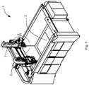
Figure 1 is a perspective view of an embodiment of a machining centre made in accordance with the invention in a subtractive configuration; -
Figure 2 shows an enlarged detail ofFigure 1 ; -
Figure 3 shows the machining centre ofFigure 1 in an additive configuration; -
Figure 4 shows an enlarged detail ofFigure 3 ; -
Figure 5 is a perspective raised elevation view of the machining centre ofFigure 1 , with the spindle axis facing downwards in a position that is suitable for subtractive operations; -
Figure 6 shows the subtractive unit rotated with respect toFigure 5 , with the spindle axis facing upwards in a suitable position for being connected to the additive unit of the machining centre ofFigure 1 ; -
Figure 7 shows the subtractive unit in the position ofFigure 6 located near the additive unit; -
Figure 8 is a view according to another perspective ofFigure 7 ; -
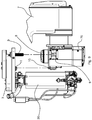
Figure 9 is a side view in a raised elevation of the subtractive unit and of the additive unit of the machining centre ofFigure 1 with the spindle axis of the subtractive unit that is coaxial with the power take-off and is not yet coupled therewith; -
Figure 10 is a perspective raised elevation view of the subtractive unit and of the additive unit of the preceding figures with the spindle axis coupled with the power take-off in the additive configuration; -
Figure 11 is a perspective bottom view of the power take-off of the machining centre ofFigure 1 . - With reference to the aforesaid figures, a CNC machining centre has been with 1 indicated overall, in particular a CNC machining centre that is suitable for machining workpieces by additive production techniques, for example by 3D printing techniques.
- The machining centre 1 may comprise, in particular, at least one
machining zone 2. Themachining zone 2 may comprise, in particular, at least one machining plane, in particular a horizontal plane, configured for supporting at least one workpiece being machined. Themachining zone 2 may be provided, in particular, with clamping means for clamping at least one workpiece in a machining position. - The machining centre 1 may comprise, in particular, at least two numerically controlled operating axes, for example two linear operating axes (for example at least one horizontal axis and at least one vertical axis). The machining centre 1 may comprise, in particular, at least one vertical linear axis (axis Z). The machining centre 1 may comprise, in particular, at least three numerically controlled operating axes. The machining centre 1 may comprise, in particular, at least two or three linear axes and at least one or two rotary axes. In particular the machining centre 1 may be, as in the specific embodiment, of the type with five numerically controlled operating axes, in particular with three linear axes (axes X, Y, Z) and two rotary axes.
- The machining centre 1 may comprise, in particular, the operating means that is suitable for moving one or more operating units in the
machining zone 2, for example controlled by the numerically controlled operating axes. This operating means may comprise, in particular, support means and/or conveying means and/or guide means and/or actuating means and/or sensor means and/or tool storage means etc. This operating means may comprise, in particular, operating means of known type that is usually used in a numeric control machining centre 1. This operating means is not explained in greater detail in this description. - The machining centre 1 may comprise, in particular, at least one
additive unit 3 configured for forming an unmachined workpiece in themachining zone 2 by additive production. Theadditive unit 3 may be arranged and may be movable above the horizontal machining plane. Theadditive unit 3 may be, in particular, coupled with support, conveying and guide means for supporting, conveying and guiding the machining centre 1. Theadditive unit 3 may be, in particular, configured for performing, through control of the numerically controlled operating axes, machining movements in the direction of one or more of the operating axes (for example the linear operating axes X, Y, Z and the rotary axes) of the machining centre. - The
additive unit 3 may comprise, in particular, a 3D printing unit. Theadditive unit 3 may comprise, in particular, at least oneoperating member 30 with a rotation axis. Theadditive unit 3 may comprise, in particular, extruding means for extruding the material that is suitable for additive production. This extruding means may comprise, in particular, theaforesaid operating member 30 with a rotation axis. Theoperating member 30 with a rotation axis may comprise, as in the specific embodiment, an extruding screw of the extruding means. Theadditive unit 3 may be configured, in particular, for receiving the drive energy of theoperating member 30 with a rotation axis from a motorized tool-holding spindle, as will be explained better further on in the description. - The machining centre 1 may comprise, in particular, at least one power take-
off 4 connected to the rotation axis of theoperating member 30 of theadditive unit 3. The machining centre 1 may comprise, in particular, motion transmission means 5 configured for connecting the power take-off 4 to the rotation axis. The power take-off 4 may comprise, in particular, an axis parallel to the rotation axis of theoperating member 30. - The power take-
off 4 may be, in particular, offset with respect to the rotation axis of theoperating member 30. The power take-off 4 may be arranged, in particular, above the horizontal machining plane. The power take-off 4 may, in particular, face downwards (for example be orthogonal to the horizontal machining plane). The power take-off 4 may be arranged, in particular, with a vertical axis. The power take-off 4 may comprise, in particular, a suitable connection for coupling with a spindle axis of a tool-holding spindle, such as for example a tapered or similar connection. - The motion transmission means 5 may comprise, in particular, speed reducing means configured for reducing a rotation speed from the power take-off 4 to the rotation axis of the
operating member 30 of theadditive unit 3, so that theoperating member 30 can rotate at a different (in particular, lower) rotation speed with respect to the spindle axis that will be connected to the power take-off 4. The speed reducing means may comprise, in particular, gear reducing means. The motion transmission means 5 may comprise, in particular, at least one transmission with a closed loop transmission flexible member (for example of the belt and/or cable and/or chain type) wound on wheel means (pulleys). - The machining centre 1 may comprise, in particular, support means 6 for supporting the
additive unit 3, the power take-off 4 and the motion transmission means 5. The support means 6 may comprise, in particular, at least one support plate arranged horizontally. The power take-off 4 may be arranged at least partially in a cavity obtained in thesupport plate 6. Therotating operating member 30 of theadditive unit 3 may comprise an overall dimension in a vertical direction that is prevalently located (at least 50%, or at least 70%, or at least 90%) or entirely below the support plate. The motion transmission means 5 may be arranged above the support plate. - The machining centre 1 may comprise, in particular, at least one
subtractive unit 7 configured for removing material from the workpiece formed in themachining zone 2 by theadditive unit 3. Thesubtractive unit 7 may comprise, in particular, at least one tool-holdingspindle 70 with amotorized spindle axis 8. Thesubtractive unit 7 may be arranged, in particular, above the horizontal machining plane. - The machining centre 1 may be configured, in particular, to adopt at least one subtractive configuration (see
Figure 1 ), in which thespindle axis 8 is not engaged with the power take-off 4 and is thus not connected to the rotation axis to drive the operatingmember 30 of theadditive unit 3. In the subtractive configuration, themotorized spindle axis 8 can carry a tool for removing material. - The machining centre 1 may be configured, in particular, to adopt at least one additive configuration (see
Figure 3 ), in which thespindle axis 8 is removably engaged on the power take-off 4 to drive the rotation axis of the operatingmember 30 of theadditive unit 3. In the additive configuration (see alsoFigure 4 orFigure 10 ), at least one part of the tool-holdingspindle 70 of thesubtractive unit 7 and at least one part of the operatingmember 30 of theadditive unit 3 are situated next to one another, where "next to" means in a horizontal direction. - In particular, it is possible, in the additive configuration, for at least 50%, or 75%, or 90% of the vertical overall dimensions of the tool-holding
spindle 70 to be situated next to the vertical overall dimensions of the operatingmember 30, where "next to" means in a horizontal direction, i.e. at the same height. - In particular, it is possible to provide, in the additive configuration, for at least 50%, or 75%, or 90% of the vertical overall dimensions of the
rotating operating member 30 of theadditive unit 3 being situated next to the vertical overall dimensions of the tool-holdingspindle 70, where "next to" means in a horizontal direction, i.e. at the same height. - In particular, it is possible to provide, in the additive configuration, for at least 50%, or 75%, or 90% of the vertical overall dimensions of the operating
member 30 of theadditive unit 3 being located in a vertical position, or height, that is lower than a lower end (at the lower position) of the power take-off 4. In particular, it is possible to provide, in the additive configuration, for at least 50%, or 75%, or 90% of the vertical overall dimensions of the operatingmember 30 of theadditive unit 3 being located in a vertical position, or height, lower than the plate of the support means 6. - In particular, it is possible to provide, in the additive configuration, for the
spindle axis 8 facing upwards, in the subtractive configuration, thespindle axis 8 facing downwards (for example tilted by 180°). It is possible to provide for a movement between the additive configuration and the subtractive configuration comprising a rotation of the tool-holdingspindle 70 of thesubtractive unit 7 around a rotation axis, in particular a horizontal rotation axis. This rotation may comprise, in particular, a rotation of 180°. - In the additive configuration, the
additive unit 3 and thesubtractive unit 7 may be, in particular, coupled together in a removable manner and may be movable together by at least one part of the, or all the, numerically controlled operating axes of the machining centre 1. - It is possible to provide, in particular, for at least one numerically controlled rotational axis of the machining centre 1 being able to be configured for controlling the aforesaid rotation of the subtractive unit 7 (in particular of the tool-holding spindle 70) in a movement between the subtractive configuration and the additive configuration.
- The support means 6 may comprise, in particular, anti-rotation means 9 configured for preventing a relative rotation between the support means 6 and the
subtractive unit 7 in the additive configuration, in particular rotation due to thespindle axis 8 of the tool-holdingspindle 70 that drives the rotation axis of the operatingmember 30 of theadditive unit 3. In particular, it is possible to provide, in the additive configuration, for the support means 6 being couplable removably with thesubtractive unit 7 by the anti-rotation means 9. The anti-rotation means 9 may comprise, in particular, one or more pegs or pins (seeFigure 9 orFigure 11 ) that are insertable and extractable in an axial direction (vertical) within corresponding recesses or slots (seeFigure 6 orFigure 9 ) to prevent rotation of the support means 6. The pegs or pins may, in particular, protrude downwards from the plate of the support means 6. The recesses or slots may be, in particular, arranged on sides (for example on two opposite sides) of thesubtractive unit 7 and be open laterally on the outside. - The support means 6 may comprise, in particular, braking means for locking the
additive unit 3 with respect to thesubtractive unit 7 in the additive configuration. The braking means may comprise locking actuators (for example with a drive by operating fluid or with an electric drive) to lock and unlock the braking means upon a command. - The support means 6 may comprise, in particular, resting means 10 (in particular in cooperation with the anti-rotation means 9 that may also act as support means) configured to discharge at least one part of the weight of the
additive unit 3 on thesubtractive unit 7 in such a manner that at least one part of the weight of theadditive unit 3 does not weigh on the power take-off 4 when the machining centre 1 is in the additive configuration. The resting means 10 may comprise, for example, at least one end of the tool-holding spindle 70 (seeFigure 6 orFigure 9 ) protruding upwards and configured for coupling in a resting manner with a corresponding rest portion (seeFigure 9 orFigure 11 ) arranged on a lower side of the support means 6. - The support means 6 may be, in particular, coupled removably with the
subtractive unit 7 by the resting means 10 in order not to load, at least partially, the weight of the additive unit 3 (and of the motion transmission means 5) on the power take-off 4. - The operation of the numeric control machining centre 1 comprises actuating a machining method for machining by removing material of the unmachined workpieces achieved by additive production techniques.
- The machining method may comprise, in particular, the step of coupling the
motorized spindle axis 8 of the tool-holdingspindle 70 of thesubtractive unit 7 with the power take-off 4 connected to the rotation axis of the operatingmember 30 of theadditive unit 3. The operatingmember 30 may comprise, as said, extruding means for processing extrudable material to perform additive production. As said, the power take-off 4 may be, in particular, offset with respect to the rotation axis of the operatingmember 30. - The machining method may comprise, in particular, the step of forming an unmachined workpiece in the
machining zone 2 with additive production by theadditive unit 3 driven by the motorized tool-holdingspindle 70 of thesubtractive unit 7. During the forming step, the operatingmember 30 of theadditive unit 3 may be rotated by themotorized spindle axis 8 engaged with the power take-off 4, whilst theadditive unit 3, being coupled with thesubtractive unit 7, may be moved by at least one part of the numerically controlled operating axes (in particular the linear axes X, Y, Z) of the machining centre 1. - After the forming step, the machining method may comprise, in particular, the step of decoupling the
spindle axis 8 from the power take-off 4 (for example by extracting axially in a vertical direction thespindle axis 8 from the power take-off 4) and thus coupling thespindle axis 8 with a tool for removing material. Coupling of the tool may comprise, in particular, automatic picking-up of the tool from a tool magazine. - Before the step of decoupling, the machining method may comprise, in particular, the step of unlocking the braking means to enable the
subtractive unit 7 to be moved without the need to move theadditive unit 3 which, in the subtractive machining step, may remain stationary. - The machining method may comprise, in particular, the step of performing a machining task to remove material by using a
subtractive unit 7, removing material from the unmachined workpiece previously formed with additive production from theadditive unit 3. - As said, it is possible to provide, during the aforesaid step of forming, for at least one part of the tool-holding
spindle 70 and at least one part of the operatingmember 30 being situated next to one another, where "next to" means in a horizontal direction. In particular, during the forming step by additive production, at least 50%, or 75%, or 90% of the vertical overall dimensions of the tool-holdingspindle 70, may be situated next to the operating member 30 (extruding means with extruder screw). In particular, during the forming step at least 50%, or 75%, or 90% of the vertical overall dimensions of the operatingmember 30 may be situated next to the tool-holdingspindle 70. - In the specific embodiment, in which the vertical overall dimensions of the
additive unit 3 is greater than the vertical overall dimensions of the tool-holdingspindle 70, the entire vertical overall dimensions of the tool-holdingspindle 70 are situated next to (in the same vertical position) at least one part of theadditive unit 3.
Claims (15)
- CNC machining centre (1), comprising:- at least one work area (2);- at least one additive unit (3) configured to form an unmachined workpiece in said work area (2) by additive production and comprising at least one operating member (30) with a rotation axis;- at least one power take-off (4) connected to said rotation axis by motion transmission means (5), said power take-off (4) being offset with respect to said rotation axis;- at least one subtractive unit (7) configured to perform removal of material from the workpiece formed in said work area (2) and comprising at least one tool-holding spindle (70) with a motorized spindle axis (8);
said machining centre (1) being configured to assume at least one subtractive configuration, in which said spindle axis (8) is not connected to said rotation axis and is able to carry a tool to remove material, and at least one additive configuration, in which said spindle axis (8) is removably connected to said power take-off (4) to drive said rotation axis. - Machining centre according to claim 1, wherein, in said additive configuration, at least a part of said tool-holding spindle (70) and at least a part of said operating member (30) are located beside one another, where "beside" is intended in a horizontal direction.
- Machining centre according to claim 1 or 2, wherein, in said additive configuration, at least 50%, or 75%, or 90% of the vertical size of said tool-holding spindle (70) is located beside the vertical size of said operating member (30), where "beside" is intended in a horizontal direction.
- Machining centre according to any one of the preceding claims, wherein, in said additive configuration, at least 50%, or 75%, or 90% of the vertical size of said operating member (30) is located beside the vertical size of said tool-holding spindle (70), where "beside" is intended in a horizontal direction.
- Machining centre according to any one of the preceding claims, wherein said power take-off (4) faces downwards and at least 50%, or 75%, or 90% of the vertical size of said operating member (30) is located at a lower vertical height with respect to a lower end of said power take-off (4), said spindle axis (8) being turned upwardly in said additive configuration.
- Machining centre according to any one of the preceding claims, wherein said spindle axis (8) faces downwards in said subtractive configuration and faces upwards in said additive configuration.
- Machining centre according to any one of the preceding claims, comprising at least two numerically controlled operating axes, at least one of which being a vertical linear axis, said subtractive group (7) being movable by said two operative axes, in said additive configuration said additive group (3) and said subtractive group (7) being removably coupled together and being movable together by said two operative axes.
- Machining centre according to any one of the preceding claims, wherein a movement between said additive configuration and said subtractive configuration comprises a rotation of said subtractive group (7) about a rotation axis, in particular a horizontal rotation axis.
- Machining centre according to any one of the preceding claims, comprising at least three numerically controlled operating axes, at least two of which being linear axes and at least one of which being a rotary axis, said subtractive group (7) being movable by means of said three operating axes, said rotary axis being configured to control a rotation of said subtractive group (7) in a movement between said subtractive configuration and said additive configuration.
- Machining centre according to any one of the preceding claims, wherein said additive group (3) comprises extruding means for extruding material suitable for additive production, said extruding means comprising said operating member (30) with a rotation axis.
- Machining centre according to any one of the preceding claims, wherein said motion transmission means (5) is configured to vary a rotation speed from said power take-off (4) to said rotation axis.
- Machining centre according to any one of the preceding claims, comprising support means (6) for supporting said additive group (3) and/or said power take-off (4) and/or said motion transmission means (5), in said additive configuration said support means (6) being removably coupled with said subtractive group (7) by anti-rotation means (9) configured to prevent a relative rotation between said support means (6) and said subtractive group (7), in particular a rotation due to the spindle axis (8) which drives said rotation axis.
- Machining centre according to any one of the preceding claims, comprising support means (6) for supporting said additive group (3) and/or said power take-off (4) and/or said motion transmission means (5), in said additive configuration said support means (6) being removably coupled with said subtractive group (7) by resting means (10) configured to discharge at least a part of the weight of said additive group (3) so that at least a part of the weight of said additive group (3) is not weighing on said power take-off (4).
- Machining method, comprising the steps of:- coupling a motorized spindle axis (8) of a tool-holding spindle (70) of a subtractive unit (7) with a power take-off (4) connected to a rotation axis of an operating member (30) of an additive group (3), said power take-off (4) being offset with respect to said rotation axis;- forming an unmachined workpiece with an additive production by means of said additive group (3) driven by said subtractive group (7);- decoupling said spindle axis (8) from said power take-off (4) and then coupling said spindle axis (8) with a tool to remove material;- performing a process for removing material from said unmachined workpiece formed with additive production by using said subtractive group (7).
- Method according to claim 14, wherein, during said step of forming, at least a part of said tool-holding spindle (70) and at least a part of said operating member (30) are located beside one another, where "beside" is intended in a horizontal direction, there being provided, in particular, that during said forming step at least 50%, or 75%, or 90% of the vertical size of said tool-holding spindle (70) is located beside said operating member (30) and/or that at least 50%, or 75%, or 90% of the vertical size of said operating member (30) is located beside said tool-holding spindle (70).
Applications Claiming Priority (1)
| Application Number | Priority Date | Filing Date | Title |
|---|---|---|---|
| IT102019000023982A IT201900023982A1 (en) | 2019-12-13 | 2019-12-13 | Numerical control machining center |
Publications (2)
| Publication Number | Publication Date |
|---|---|
| EP3835030A1 true EP3835030A1 (en) | 2021-06-16 |
| EP3835030B1 EP3835030B1 (en) | 2024-12-18 |
Family
ID=70155045
Family Applications (1)
| Application Number | Title | Priority Date | Filing Date |
|---|---|---|---|
| EP20210778.5A Active EP3835030B1 (en) | 2019-12-13 | 2020-11-30 | Cnc machining centre |
Country Status (5)
| Country | Link |
|---|---|
| US (1) | US11806922B2 (en) |
| EP (1) | EP3835030B1 (en) |
| CN (1) | CN112975522B (en) |
| IT (1) | IT201900023982A1 (en) |
| PL (1) | PL3835030T3 (en) |
Cited By (1)
| Publication number | Priority date | Publication date | Assignee | Title |
|---|---|---|---|---|
| CN116572065A (en) * | 2023-06-27 | 2023-08-11 | 西安交通大学 | A compound processing machine tool for adding and subtracting materials |
Families Citing this family (1)
| Publication number | Priority date | Publication date | Assignee | Title |
|---|---|---|---|---|
| CN116586663A (en) * | 2023-05-15 | 2023-08-15 | 浙江大学高端装备研究院 | A moldless precision molding device and manufacturing method based on granular thermoplastic materials |
Citations (4)
| Publication number | Priority date | Publication date | Assignee | Title |
|---|---|---|---|---|
| EP1614497A1 (en) * | 2004-07-09 | 2006-01-11 | Ingersoll Machine Tools, Inc. | Method and apparatus for repairing or building up surfaces on a workpiece while the workpiece is mounted on a machine tool |
| EP3170620A1 (en) * | 2015-11-17 | 2017-05-24 | General Electric Company | Combined additive manufacturing and machining system |
| US20180194076A1 (en) * | 2017-01-12 | 2018-07-12 | Voxei8, Inc. | Techniques for hybrid additive and substractive manufacturing |
| GB2560737A (en) * | 2017-03-22 | 2018-09-26 | Hybrid Manufacturing Tech Limited | A machine tool |
Family Cites Families (12)
| Publication number | Priority date | Publication date | Assignee | Title |
|---|---|---|---|---|
| DE19533960C2 (en) * | 1995-09-13 | 1997-08-28 | Fraunhofer Ges Forschung | Method and device for producing metallic workpieces |
| KR200407970Y1 (en) * | 2005-11-18 | 2006-02-06 | (주)하이텍알씨디코리아 | Space-saving servo motor |
| DE102014224176A1 (en) * | 2014-11-26 | 2016-06-02 | Weeke Bohrsysteme Gmbh | Device for the formation of solids |
| JP5937249B1 (en) * | 2015-03-20 | 2016-06-22 | Dmg森精機株式会社 | Processing machine |
| JP5940712B1 (en) * | 2015-05-25 | 2016-06-29 | Dmg森精機株式会社 | Processing machine |
| CN108367403B (en) * | 2016-08-17 | 2019-07-09 | 山崎马扎克公司 | Complex machining device and combined machining method |
| JP2018027612A (en) * | 2017-05-22 | 2018-02-22 | ヤマザキマザック株式会社 | Composite machining apparatus |
| CN107336023B (en) * | 2017-08-03 | 2023-08-18 | 机械科学研究总院海西(福建)分院有限公司 | Composite machining center for increasing and decreasing materials |
| CN108127917A (en) * | 2018-02-06 | 2018-06-08 | 东北大学 | A kind of lathe of small-sized five-shaft numerical control changeable material processing |
| CN109604598A (en) * | 2019-01-09 | 2019-04-12 | 深圳光韵达光电科技股份有限公司 | A composite processing equipment for adding and subtracting materials |
| CN109968040B (en) * | 2019-04-18 | 2021-05-18 | 江南大学 | A composite manufacturing equipment for adding and subtracting materials |
| CN110497612A (en) * | 2019-08-19 | 2019-11-26 | 兰州理工大学 | A compound processing machine head and equipment for adding and subtracting materials |
-
2019
- 2019-12-13 IT IT102019000023982A patent/IT201900023982A1/en unknown
-
2020
- 2020-11-30 PL PL20210778.5T patent/PL3835030T3/en unknown
- 2020-11-30 EP EP20210778.5A patent/EP3835030B1/en active Active
- 2020-12-11 US US17/118,714 patent/US11806922B2/en active Active
- 2020-12-11 CN CN202011461503.0A patent/CN112975522B/en active Active
Patent Citations (4)
| Publication number | Priority date | Publication date | Assignee | Title |
|---|---|---|---|---|
| EP1614497A1 (en) * | 2004-07-09 | 2006-01-11 | Ingersoll Machine Tools, Inc. | Method and apparatus for repairing or building up surfaces on a workpiece while the workpiece is mounted on a machine tool |
| EP3170620A1 (en) * | 2015-11-17 | 2017-05-24 | General Electric Company | Combined additive manufacturing and machining system |
| US20180194076A1 (en) * | 2017-01-12 | 2018-07-12 | Voxei8, Inc. | Techniques for hybrid additive and substractive manufacturing |
| GB2560737A (en) * | 2017-03-22 | 2018-09-26 | Hybrid Manufacturing Tech Limited | A machine tool |
Cited By (1)
| Publication number | Priority date | Publication date | Assignee | Title |
|---|---|---|---|---|
| CN116572065A (en) * | 2023-06-27 | 2023-08-11 | 西安交通大学 | A compound processing machine tool for adding and subtracting materials |
Also Published As
| Publication number | Publication date |
|---|---|
| CN112975522A (en) | 2021-06-18 |
| IT201900023982A1 (en) | 2021-06-13 |
| CN112975522B (en) | 2026-03-10 |
| US20210178544A1 (en) | 2021-06-17 |
| US11806922B2 (en) | 2023-11-07 |
| PL3835030T3 (en) | 2025-04-07 |
| EP3835030B1 (en) | 2024-12-18 |
Similar Documents
| Publication | Publication Date | Title |
|---|---|---|
| CN109249040B (en) | Loading and unloading device for lathe | |
| EP0348715A1 (en) | Apparatus for the automatic adjustment of pallet workpiece support members | |
| KR102616227B1 (en) | Parts unloader device of machine tool | |
| EP4257317B1 (en) | Numerical-control work centre for machining plates of glass or plates of natural or synthetic stone material with machining head having an auxiliary plate-supporting unit, and machining method | |
| EP0063161A1 (en) | Industrial robot | |
| US11806922B2 (en) | CNC machining centre | |
| CN117139679B (en) | Flexible numerical control drilling device for brake pad | |
| US20090053000A1 (en) | Compact High Precision Multiple Spindle Computer Controlled Machine Tool | |
| CN212019527U (en) | Vertical machine tool | |
| CN116638379B (en) | Integrated processing machine tool | |
| CN113664546A (en) | Main shaft inverted compound machine tool system | |
| CN119260073A (en) | Cross arm automatic tool changing device and tool changing method for circular shearing machine | |
| CN214291134U (en) | Double-servo broaching machine with automatic tool changing function | |
| KR102530302B1 (en) | Material loading apparatus for cnc lathe | |
| CN116276157A (en) | Multi-channel combined integrated automatic machine tool | |
| US5735029A (en) | Flexible arbor mill machine | |
| JP2019503878A (en) | Machine Tools | |
| CN220660065U (en) | Automatic feeding and discharging structure of drilling and milling machining center | |
| EP4450244A1 (en) | Machine for machining parts and method of operation thereof | |
| CN217529232U (en) | Truss manipulator intelligent workstation is joined in marriage to numerical control lathe | |
| CN215316999U (en) | Numerical control lathe elevating gear | |
| CN223572644U (en) | A palletizing and unloading assembly and a high-efficiency CNC machining center | |
| EP4257319B1 (en) | Numerical-control work centre for machining plates of glass or plates of natural or synthetic stone material, and corresponding machining method | |
| CN222003971U (en) | Graphite crucible machining production line | |
| CN221540251U (en) | Automatic tool changing boring and milling machine tool for graphite crucible processing |
Legal Events
| Date | Code | Title | Description |
|---|---|---|---|
| PUAI | Public reference made under article 153(3) epc to a published international application that has entered the european phase |
Free format text: ORIGINAL CODE: 0009012 |
|
| STAA | Information on the status of an ep patent application or granted ep patent |
Free format text: STATUS: THE APPLICATION HAS BEEN PUBLISHED |
|
| AK | Designated contracting states |
Kind code of ref document: A1 Designated state(s): AL AT BE BG CH CY CZ DE DK EE ES FI FR GB GR HR HU IE IS IT LI LT LU LV MC MK MT NL NO PL PT RO RS SE SI SK SM TR |
|
| STAA | Information on the status of an ep patent application or granted ep patent |
Free format text: STATUS: REQUEST FOR EXAMINATION WAS MADE |
|
| 17P | Request for examination filed |
Effective date: 20210910 |
|
| RBV | Designated contracting states (corrected) |
Designated state(s): AL AT BE BG CH CY CZ DE DK EE ES FI FR GB GR HR HU IE IS IT LI LT LU LV MC MK MT NL NO PL PT RO RS SE SI SK SM TR |
|
| P01 | Opt-out of the competence of the unified patent court (upc) registered |
Effective date: 20230519 |
|
| RIC1 | Information provided on ipc code assigned before grant |
Ipc: B33Y 40/00 20200101ALN20240607BHEP Ipc: B33Y 30/00 20150101ALN20240607BHEP Ipc: B33Y 10/00 20150101ALN20240607BHEP Ipc: B22F 12/82 20210101ALI20240607BHEP Ipc: B22F 12/00 20210101ALI20240607BHEP Ipc: B23Q 37/00 20060101ALI20240607BHEP Ipc: B23Q 3/12 20060101ALI20240607BHEP Ipc: B23K 28/02 20140101ALI20240607BHEP Ipc: B22F 10/66 20210101ALI20240607BHEP Ipc: B29C 64/188 20170101ALI20240607BHEP Ipc: B23Q 39/02 20060101ALI20240607BHEP Ipc: B23P 23/04 20060101ALI20240607BHEP Ipc: B29C 64/106 20170101AFI20240607BHEP |
|
| GRAP | Despatch of communication of intention to grant a patent |
Free format text: ORIGINAL CODE: EPIDOSNIGR1 |
|
| STAA | Information on the status of an ep patent application or granted ep patent |
Free format text: STATUS: GRANT OF PATENT IS INTENDED |
|
| RIC1 | Information provided on ipc code assigned before grant |
Ipc: B33Y 40/00 20200101ALN20240626BHEP Ipc: B33Y 30/00 20150101ALN20240626BHEP Ipc: B33Y 10/00 20150101ALN20240626BHEP Ipc: B22F 12/82 20210101ALI20240626BHEP Ipc: B22F 12/00 20210101ALI20240626BHEP Ipc: B23Q 37/00 20060101ALI20240626BHEP Ipc: B23Q 3/12 20060101ALI20240626BHEP Ipc: B23K 28/02 20140101ALI20240626BHEP Ipc: B22F 10/66 20210101ALI20240626BHEP Ipc: B29C 64/188 20170101ALI20240626BHEP Ipc: B23Q 39/02 20060101ALI20240626BHEP Ipc: B23P 23/04 20060101ALI20240626BHEP Ipc: B29C 64/106 20170101AFI20240626BHEP |
|
| INTG | Intention to grant announced |
Effective date: 20240725 |
|
| GRAS | Grant fee paid |
Free format text: ORIGINAL CODE: EPIDOSNIGR3 |
|
| GRAA | (expected) grant |
Free format text: ORIGINAL CODE: 0009210 |
|
| STAA | Information on the status of an ep patent application or granted ep patent |
Free format text: STATUS: THE PATENT HAS BEEN GRANTED |
|
| AK | Designated contracting states |
Kind code of ref document: B1 Designated state(s): AL AT BE BG CH CY CZ DE DK EE ES FI FR GB GR HR HU IE IS IT LI LT LU LV MC MK MT NL NO PL PT RO RS SE SI SK SM TR |
|
| REG | Reference to a national code |
Ref country code: CH Ref legal event code: EP |
|
| REG | Reference to a national code |
Ref country code: DE Ref legal event code: R096 Ref document number: 602020043278 Country of ref document: DE |
|
| REG | Reference to a national code |
Ref country code: IE Ref legal event code: FG4D |
|
| REG | Reference to a national code |
Ref country code: NL Ref legal event code: FP |
|
| REG | Reference to a national code |
Ref country code: LT Ref legal event code: MG9D |
|
| PG25 | Lapsed in a contracting state [announced via postgrant information from national office to epo] |
Ref country code: HR Free format text: LAPSE BECAUSE OF FAILURE TO SUBMIT A TRANSLATION OF THE DESCRIPTION OR TO PAY THE FEE WITHIN THE PRESCRIBED TIME-LIMIT Effective date: 20241218 |
|
| PG25 | Lapsed in a contracting state [announced via postgrant information from national office to epo] |
Ref country code: FI Free format text: LAPSE BECAUSE OF FAILURE TO SUBMIT A TRANSLATION OF THE DESCRIPTION OR TO PAY THE FEE WITHIN THE PRESCRIBED TIME-LIMIT Effective date: 20241218 |
|
| PG25 | Lapsed in a contracting state [announced via postgrant information from national office to epo] |
Ref country code: BG Free format text: LAPSE BECAUSE OF FAILURE TO SUBMIT A TRANSLATION OF THE DESCRIPTION OR TO PAY THE FEE WITHIN THE PRESCRIBED TIME-LIMIT Effective date: 20241218 |
|
| PG25 | Lapsed in a contracting state [announced via postgrant information from national office to epo] |
Ref country code: NO Free format text: LAPSE BECAUSE OF FAILURE TO SUBMIT A TRANSLATION OF THE DESCRIPTION OR TO PAY THE FEE WITHIN THE PRESCRIBED TIME-LIMIT Effective date: 20250318 |
|
| PG25 | Lapsed in a contracting state [announced via postgrant information from national office to epo] |
Ref country code: LV Free format text: LAPSE BECAUSE OF FAILURE TO SUBMIT A TRANSLATION OF THE DESCRIPTION OR TO PAY THE FEE WITHIN THE PRESCRIBED TIME-LIMIT Effective date: 20241218 Ref country code: GR Free format text: LAPSE BECAUSE OF FAILURE TO SUBMIT A TRANSLATION OF THE DESCRIPTION OR TO PAY THE FEE WITHIN THE PRESCRIBED TIME-LIMIT Effective date: 20250319 |
|
| PG25 | Lapsed in a contracting state [announced via postgrant information from national office to epo] |
Ref country code: RS Free format text: LAPSE BECAUSE OF FAILURE TO SUBMIT A TRANSLATION OF THE DESCRIPTION OR TO PAY THE FEE WITHIN THE PRESCRIBED TIME-LIMIT Effective date: 20250318 |
|
| REG | Reference to a national code |
Ref country code: AT Ref legal event code: MK05 Ref document number: 1751927 Country of ref document: AT Kind code of ref document: T Effective date: 20241218 |
|
| PG25 | Lapsed in a contracting state [announced via postgrant information from national office to epo] |
Ref country code: SM Free format text: LAPSE BECAUSE OF FAILURE TO SUBMIT A TRANSLATION OF THE DESCRIPTION OR TO PAY THE FEE WITHIN THE PRESCRIBED TIME-LIMIT Effective date: 20241218 |
|
| PG25 | Lapsed in a contracting state [announced via postgrant information from national office to epo] |
Ref country code: ES Free format text: LAPSE BECAUSE OF FAILURE TO SUBMIT A TRANSLATION OF THE DESCRIPTION OR TO PAY THE FEE WITHIN THE PRESCRIBED TIME-LIMIT Effective date: 20241218 |
|
| PG25 | Lapsed in a contracting state [announced via postgrant information from national office to epo] |
Ref country code: IS Free format text: LAPSE BECAUSE OF FAILURE TO SUBMIT A TRANSLATION OF THE DESCRIPTION OR TO PAY THE FEE WITHIN THE PRESCRIBED TIME-LIMIT Effective date: 20250418 |
|
| PG25 | Lapsed in a contracting state [announced via postgrant information from national office to epo] |
Ref country code: PT Free format text: LAPSE BECAUSE OF FAILURE TO SUBMIT A TRANSLATION OF THE DESCRIPTION OR TO PAY THE FEE WITHIN THE PRESCRIBED TIME-LIMIT Effective date: 20250421 |
|
| PG25 | Lapsed in a contracting state [announced via postgrant information from national office to epo] |
Ref country code: EE Free format text: LAPSE BECAUSE OF FAILURE TO SUBMIT A TRANSLATION OF THE DESCRIPTION OR TO PAY THE FEE WITHIN THE PRESCRIBED TIME-LIMIT Effective date: 20241218 |
|
| PG25 | Lapsed in a contracting state [announced via postgrant information from national office to epo] |
Ref country code: AT Free format text: LAPSE BECAUSE OF FAILURE TO SUBMIT A TRANSLATION OF THE DESCRIPTION OR TO PAY THE FEE WITHIN THE PRESCRIBED TIME-LIMIT Effective date: 20241218 Ref country code: RO Free format text: LAPSE BECAUSE OF FAILURE TO SUBMIT A TRANSLATION OF THE DESCRIPTION OR TO PAY THE FEE WITHIN THE PRESCRIBED TIME-LIMIT Effective date: 20241218 |
|
| PG25 | Lapsed in a contracting state [announced via postgrant information from national office to epo] |
Ref country code: SK Free format text: LAPSE BECAUSE OF FAILURE TO SUBMIT A TRANSLATION OF THE DESCRIPTION OR TO PAY THE FEE WITHIN THE PRESCRIBED TIME-LIMIT Effective date: 20241218 |
|
| PG25 | Lapsed in a contracting state [announced via postgrant information from national office to epo] |
Ref country code: CZ Free format text: LAPSE BECAUSE OF FAILURE TO SUBMIT A TRANSLATION OF THE DESCRIPTION OR TO PAY THE FEE WITHIN THE PRESCRIBED TIME-LIMIT Effective date: 20241218 |
|
| PG25 | Lapsed in a contracting state [announced via postgrant information from national office to epo] |
Ref country code: SE Free format text: LAPSE BECAUSE OF FAILURE TO SUBMIT A TRANSLATION OF THE DESCRIPTION OR TO PAY THE FEE WITHIN THE PRESCRIBED TIME-LIMIT Effective date: 20241218 |
|
| REG | Reference to a national code |
Ref country code: DE Ref legal event code: R097 Ref document number: 602020043278 Country of ref document: DE |
|
| PG25 | Lapsed in a contracting state [announced via postgrant information from national office to epo] |
Ref country code: DK Free format text: LAPSE BECAUSE OF FAILURE TO SUBMIT A TRANSLATION OF THE DESCRIPTION OR TO PAY THE FEE WITHIN THE PRESCRIBED TIME-LIMIT Effective date: 20241218 |
|
| PLBE | No opposition filed within time limit |
Free format text: ORIGINAL CODE: 0009261 |
|
| STAA | Information on the status of an ep patent application or granted ep patent |
Free format text: STATUS: NO OPPOSITION FILED WITHIN TIME LIMIT |
|
| REG | Reference to a national code |
Ref country code: CH Ref legal event code: L10 Free format text: ST27 STATUS EVENT CODE: U-0-0-L10-L00 (AS PROVIDED BY THE NATIONAL OFFICE) Effective date: 20251029 |
|
| 26N | No opposition filed |
Effective date: 20250919 |
|
| PGFP | Annual fee paid to national office [announced via postgrant information from national office to epo] |
Ref country code: NL Payment date: 20251119 Year of fee payment: 6 |
|
| PGFP | Annual fee paid to national office [announced via postgrant information from national office to epo] |
Ref country code: DE Payment date: 20251118 Year of fee payment: 6 |
|
| PGFP | Annual fee paid to national office [announced via postgrant information from national office to epo] |
Ref country code: IT Payment date: 20251013 Year of fee payment: 6 |
|
| PGFP | Annual fee paid to national office [announced via postgrant information from national office to epo] |
Ref country code: PL Payment date: 20251119 Year of fee payment: 6 |
|
| REG | Reference to a national code |
Ref country code: CH Ref legal event code: H13 Free format text: ST27 STATUS EVENT CODE: U-0-0-H10-H13 (AS PROVIDED BY THE NATIONAL OFFICE) Effective date: 20260623 |
|
| PG25 | Lapsed in a contracting state [announced via postgrant information from national office to epo] |
Ref country code: LT Free format text: LAPSE BECAUSE OF FAILURE TO SUBMIT A TRANSLATION OF THE DESCRIPTION OR TO PAY THE FEE WITHIN THE PRESCRIBED TIME-LIMIT Effective date: 20241218 |
|
| PG25 | Lapsed in a contracting state [announced via postgrant information from national office to epo] |
Ref country code: MC Free format text: LAPSE BECAUSE OF FAILURE TO SUBMIT A TRANSLATION OF THE DESCRIPTION OR TO PAY THE FEE WITHIN THE PRESCRIBED TIME-LIMIT Effective date: 20241218 |
|
| PG25 | Lapsed in a contracting state [announced via postgrant information from national office to epo] |
Ref country code: LU Free format text: LAPSE BECAUSE OF NON-PAYMENT OF DUE FEES Effective date: 20251130 Ref country code: CH Free format text: LAPSE BECAUSE OF NON-PAYMENT OF DUE FEES Effective date: 20251130 |