EP3835026A1 - Multi-part core insert - Google Patents
Multi-part core insert Download PDFInfo
- Publication number
- EP3835026A1 EP3835026A1 EP20210163.0A EP20210163A EP3835026A1 EP 3835026 A1 EP3835026 A1 EP 3835026A1 EP 20210163 A EP20210163 A EP 20210163A EP 3835026 A1 EP3835026 A1 EP 3835026A1
- Authority
- EP
- European Patent Office
- Prior art keywords
- fastening element
- core part
- lower core
- insert
- core
- Prior art date
- Legal status (The legal status is an assumption and is not a legal conclusion. Google has not performed a legal analysis and makes no representation as to the accuracy of the status listed.)
- Withdrawn
Links
- 238000002347 injection Methods 0.000 claims abstract description 41
- 239000007924 injection Substances 0.000 claims abstract description 41
- 238000001746 injection moulding Methods 0.000 abstract description 16
- 238000004519 manufacturing process Methods 0.000 abstract description 5
- 238000007493 shaping process Methods 0.000 abstract description 4
- 239000000463 material Substances 0.000 description 10
- 239000000110 cooling liquid Substances 0.000 description 7
- 239000002826 coolant Substances 0.000 description 5
- 230000008901 benefit Effects 0.000 description 4
- 230000008859 change Effects 0.000 description 3
- 238000001816 cooling Methods 0.000 description 3
- 238000013461 design Methods 0.000 description 3
- 230000000694 effects Effects 0.000 description 3
- 239000000155 melt Substances 0.000 description 3
- 230000001154 acute effect Effects 0.000 description 2
- 230000015572 biosynthetic process Effects 0.000 description 2
- 239000011248 coating agent Substances 0.000 description 2
- 238000000576 coating method Methods 0.000 description 2
- 238000000465 moulding Methods 0.000 description 2
- 229910000831 Steel Inorganic materials 0.000 description 1
- 230000006978 adaptation Effects 0.000 description 1
- 230000005540 biological transmission Effects 0.000 description 1
- 238000006243 chemical reaction Methods 0.000 description 1
- 230000006835 compression Effects 0.000 description 1
- 238000007906 compression Methods 0.000 description 1
- 238000007667 floating Methods 0.000 description 1
- 239000012530 fluid Substances 0.000 description 1
- 239000008187 granular material Substances 0.000 description 1
- 230000007246 mechanism Effects 0.000 description 1
- 238000000034 method Methods 0.000 description 1
- 238000012986 modification Methods 0.000 description 1
- 230000004048 modification Effects 0.000 description 1
- 230000008569 process Effects 0.000 description 1
- 238000012545 processing Methods 0.000 description 1
- 230000009467 reduction Effects 0.000 description 1
- 238000007789 sealing Methods 0.000 description 1
- 230000006641 stabilisation Effects 0.000 description 1
- 238000011105 stabilization Methods 0.000 description 1
- 239000010959 steel Substances 0.000 description 1
- 238000012546 transfer Methods 0.000 description 1
- 238000013022 venting Methods 0.000 description 1
- XLYOFNOQVPJJNP-UHFFFAOYSA-N water Substances O XLYOFNOQVPJJNP-UHFFFAOYSA-N 0.000 description 1
Images


Classifications
-
- B—PERFORMING OPERATIONS; TRANSPORTING
- B29—WORKING OF PLASTICS; WORKING OF SUBSTANCES IN A PLASTIC STATE IN GENERAL
- B29C—SHAPING OR JOINING OF PLASTICS; SHAPING OF MATERIAL IN A PLASTIC STATE, NOT OTHERWISE PROVIDED FOR; AFTER-TREATMENT OF THE SHAPED PRODUCTS, e.g. REPAIRING
- B29C45/00—Injection moulding, i.e. forcing the required volume of moulding material through a nozzle into a closed mould; Apparatus therefor
- B29C45/17—Component parts, details or accessories; Auxiliary operations
- B29C45/26—Moulds
- B29C45/261—Moulds having tubular mould cavities
- B29C45/2612—Moulds having tubular mould cavities for manufacturing tubular articles with an annular groove
-
- B—PERFORMING OPERATIONS; TRANSPORTING
- B29—WORKING OF PLASTICS; WORKING OF SUBSTANCES IN A PLASTIC STATE IN GENERAL
- B29C—SHAPING OR JOINING OF PLASTICS; SHAPING OF MATERIAL IN A PLASTIC STATE, NOT OTHERWISE PROVIDED FOR; AFTER-TREATMENT OF THE SHAPED PRODUCTS, e.g. REPAIRING
- B29C45/00—Injection moulding, i.e. forcing the required volume of moulding material through a nozzle into a closed mould; Apparatus therefor
- B29C45/17—Component parts, details or accessories; Auxiliary operations
- B29C45/26—Moulds
- B29C45/36—Moulds having means for locating or centering cores
-
- B—PERFORMING OPERATIONS; TRANSPORTING
- B29—WORKING OF PLASTICS; WORKING OF SUBSTANCES IN A PLASTIC STATE IN GENERAL
- B29C—SHAPING OR JOINING OF PLASTICS; SHAPING OF MATERIAL IN A PLASTIC STATE, NOT OTHERWISE PROVIDED FOR; AFTER-TREATMENT OF THE SHAPED PRODUCTS, e.g. REPAIRING
- B29C45/00—Injection moulding, i.e. forcing the required volume of moulding material through a nozzle into a closed mould; Apparatus therefor
- B29C45/17—Component parts, details or accessories; Auxiliary operations
- B29C45/26—Moulds
- B29C45/261—Moulds having tubular mould cavities
-
- B—PERFORMING OPERATIONS; TRANSPORTING
- B29—WORKING OF PLASTICS; WORKING OF SUBSTANCES IN A PLASTIC STATE IN GENERAL
- B29C—SHAPING OR JOINING OF PLASTICS; SHAPING OF MATERIAL IN A PLASTIC STATE, NOT OTHERWISE PROVIDED FOR; AFTER-TREATMENT OF THE SHAPED PRODUCTS, e.g. REPAIRING
- B29C45/00—Injection moulding, i.e. forcing the required volume of moulding material through a nozzle into a closed mould; Apparatus therefor
- B29C45/17—Component parts, details or accessories; Auxiliary operations
- B29C45/26—Moulds
- B29C45/2673—Moulds with exchangeable mould parts, e.g. cassette moulds
- B29C45/2675—Mounting of exchangeable mould inserts
-
- B—PERFORMING OPERATIONS; TRANSPORTING
- B29—WORKING OF PLASTICS; WORKING OF SUBSTANCES IN A PLASTIC STATE IN GENERAL
- B29C—SHAPING OR JOINING OF PLASTICS; SHAPING OF MATERIAL IN A PLASTIC STATE, NOT OTHERWISE PROVIDED FOR; AFTER-TREATMENT OF THE SHAPED PRODUCTS, e.g. REPAIRING
- B29C45/00—Injection moulding, i.e. forcing the required volume of moulding material through a nozzle into a closed mould; Apparatus therefor
- B29C45/17—Component parts, details or accessories; Auxiliary operations
- B29C45/26—Moulds
- B29C45/33—Moulds having transversely, e.g. radially, movable mould parts
-
- B—PERFORMING OPERATIONS; TRANSPORTING
- B29—WORKING OF PLASTICS; WORKING OF SUBSTANCES IN A PLASTIC STATE IN GENERAL
- B29K—INDEXING SCHEME ASSOCIATED WITH SUBCLASSES B29B, B29C OR B29D, RELATING TO MOULDING MATERIALS OR TO MATERIALS FOR MOULDS, REINFORCEMENTS, FILLERS OR PREFORMED PARTS, e.g. INSERTS
- B29K2105/00—Condition, form or state of moulded material or of the material to be shaped
- B29K2105/25—Solid
- B29K2105/253—Preform
- B29K2105/258—Tubular
Definitions
- the present invention relates to a multi-part core insert for an injection mold for the production of preforms, comprising a two-part core with a longitudinal axis, the two-part core having a lower core part and an upper core part arranged in the direction of the longitudinal axis next to the lower core part, and a fastening element, the Fastening element is essentially hollow-cylindrical and has a longitudinal axis, the fastening element having an opening parallel to the longitudinal axis for receiving the upper core part, and wherein the upper core part can be fastened to one end of the lower core part with the fastening element.
- Such core inserts are mainly used in injection molds for the injection molding of preforms.
- Such preforms can, for example, be PET preforms which are blown into PET bottles in a further processing step.
- a granulate made of plastic is plasticized, i.e. melted and homogenized.
- the plasticized melt is then injected into a mold space of the injection mold under high pressure.
- Part of this mold space and thus part of the shape of the preform is determined by the outer contour of the core insert, namely the inner part or the inner surface of the preform to be produced.
- the core insert After the injection, the plasticized melt remains in the mold space until it has cooled down enough that the preform is stable and can be removed.
- the core insert In order to ensure rapid cooling of the plasticized melt, the core insert often has a cooling system that cools the inside of the preform.
- a channel system is formed in the interior of the core insert, through which a cooling liquid is guided.
- core inserts of such injection molds are designed in one piece. In this case, the entire core insert must be replaced when the outer contour of a core insert is worn out. It is not uncommon for the injection molds described to be used to produce preforms with different contours. In order to change the contour of a preform, at least the shaping part of the core insert has to be replaced. In the case of one-piece core inserts, however, this also means the complete replacement of the core insert. However, the complete replacement of the core inserts is both material and time-consuming.
- Core inserts are therefore known from the prior art which provide a two-part core insert, only part of the core insert contributing to the shape of the preform and thus being exposed to increased wear. In the case of core inserts of this type, it is sufficient if only the corresponding part of the core insert is exchanged if it is worn out or if a different shape of preforms is to be produced. In this way, material can be saved.
- both parts of the core insert are reliably connected to one another in order to minimize rejects during the production of the preforms. If the parts are not reliably connected to one another and the part that contributes to the shape of the preform can move during the injection process, for example by performing a tilting movement relative to the other part of the core insert, this leads to an undesired and incalculable change in the mold space in which the preform is made. Such uncontrollable changes in the mold space lead at least to changed wall thicknesses of the preform, which in the worst case lead to the preform being unusable. In addition, there is a risk that coolant will leak between the lower and upper core part.
- a support ring which connects the two parts of the core insert with each other, in which the support ring tensions the part of the core insert that contributes to the shape of the preform in the direction of the other part of the core insert that does not contribute to the shape of the preform .
- the support ring extends along the lower core part, which does not contribute to the shape, so that the support ring can be attached to a base plate which is located at an end of the rear core part facing away from the front core part of the core insert.
- a multi-part core insert as described above, in which the fastening element and the upper core part are designed in such a way that, when the upper core part is received in the opening, a form-fitting and / or force-fitting connection between the im Fastening element received upper core part and the fastening element can be produced, and in which the fastening element and the lower core part are designed such that the fastening element only in one position or in several positions that differ by a rotation of the fastening element relative to the lower core part about the longitudinal axis , can be attached to the lower core part, with only a finite number of positions, preferably a maximum of four positions, of the fastening element relative to the lower core part are possible.
- the advantage of the fastening element according to the invention is that it is used to fasten the upper core part directly to the lower core part, independently of the fastening of the lower core part to a base plate.
- the upper core part can be exchanged particularly easily, in that only the fastening element has to be detached from the lower core part, which is more easily accessible than a base plate on which several core inserts are often arranged directly next to one another. The downtimes of an injection molding system due to conversion work are thus minimized.
- the fastening element is designed in such a way that the upper core part can be received in the fastening element.
- the fastening element has a through opening, so that the fastening element has an essentially hollow-cylindrical shape.
- the through opening extends parallel to the longitudinal axis. Through openings that extend along the longitudinal axis are also considered to be aligned parallel to the longitudinal axis.
- the upper core part of the core insert can be received in the through opening.
- the upper and lower core parts also have a substantially cylindrical cross section.
- the term “essentially cylindrical” or “essentially hollow cylindrical” does not exclusively refer to exactly round shapes. Rather, core inserts with other cross-sectional shapes, for example squares, hexagons or other polygons, are also conceivable.
- the cross-sectional shape of the opening of the fastening element only has to be adapted to the cross-sectional shape of the upper core part.
- the fastening element can perform other functions, such as providing a fluid channel or providing a holder for e.g. a sensor. In any case, the fastening element can only be fastened to the lower core part in predetermined positions.
- the multi-part core insert is designed in one embodiment such that the upper core part and the opening of the fastening element have mutually corresponding stop surfaces, the stop surfaces preferably being designed such that an axial relative movement of the fastening element with respect to the upper Core part in the direction of the lower core part facing part of the upper core part and / or a radial relative movement between the fastening element and the upper core part is limited.
- the fastening element can only be placed on one side of the upper core part in order to assemble the multi-part core insert according to the invention.
- the diameter of the upper core part can be greater than a diameter of the opening of the fastening element, so that it is not possible to lead the upper core part completely through the fastening element.
- the corresponding stop surfaces of the opening of the fastening element and of the upper core part are designed conically.
- a conical surface is a section on an outer surface (lateral surface) of a truncated cone or a cone. In this way, a holding force can be exerted particularly effectively on the upper core part in a direction parallel to the longitudinal axis.
- the cone is designed in such a way that its outer diameter increases in the direction of the lower core part.
- the corresponding stop surfaces can have two stop surface sections arranged at an angle to one another, preferably perpendicular to one another, with one of the contact surface sections preferably being parallel to the longitudinal axis of the fastening element.
- a combination with a conical stop surface is also conceivable.
- the fastening element according to the invention is designed such that the stop surface of the fastening element and the stop surface of the upper core part are adapted to one another with a loose fit.
- the clearance fit of the two stop surfaces means that the upper core part is also floatingly supported in the fastening element when the multi-part core insert is in an assembled state.
- a clearance fit means that the stop surfaces are not in contact with one another or not in full circumference, at least in the radial direction, but that there is a gap of, for example, a few micrometers.
- the upper core part received in the fastening element is fastened to the lower core part by the fastening element in an assembled state of the multi-part core insert.
- the longitudinal axes of the upper and lower core parts and of the fastening element are parallel to one another. All three components preferably have a common central longitudinal axis, which describes a rotational symmetry of the multi-part core insert.
- the mutually facing end surfaces of the upper and lower core parts preferably touch one another. It is particularly preferred that the two end faces are flush with one another. For example, both end faces could have the same inside and / or outside diameter.
- Part of an outer contour of the upper core part contributes to the inner shape of the preform to be produced, while the lower core part does not primarily contribute to the shape of the preform the attachment of the core insert to a base plate, i.e. a tool holder, as well as the supply and discharge of coolant is used.
- the shaping outer contour of the upper core part by means of permanent water supply and drainage.
- the bores in the lower and upper core part are preferably designed in such a way that their cross-section is essentially identical in order to avoid unwanted turbulence in the cooling liquid.
- At least one of the two end faces has a groove for receiving a sealing element, e.g. B. an O-ring. If the O-ring is in the groove and the lower and upper core parts are connected to one another, then the O-ring seals the two sections against one another so that no coolant can escape.
- a sealing element e.g. B. an O-ring.
- the fastening element, the upper core part and the lower core part are designed such that only a finite number of positions of the upper core part relative to the lower core part is possible.
- the fastening element according to the invention allows the upper core part to be fastened to the lower core part only in certain angular positions, so that in every position it is ensured that the bores for the cooling liquid in the upper and lower core part are flush with one another.
- the fastening element and / or the lower core part can in one embodiment have a projection or a recess into which the projection, for example a locking pin, engages when the multi-part core insert is assembled. There is thus only one position in which the fastening element is fastened relative to the lower core part.
- the multi-part core insert in one embodiment has a configuration such that the lower core part and the fastening element have mutually corresponding contact surfaces which are in contact with one another in an assembled state of the multi-part core insert.
- the mutually corresponding contact surfaces of the lower core part and the fastening element are equipped with two contact surface sections at an angle to one another, preferably perpendicular, one of the contact surface sections of the lower core part and the fastening element preferably being aligned parallel to the longitudinal axis of the fastening element .
- the two contact surface sections at an angle to one another enable better holding of the fastening element and thus better fixation between the upper and lower core parts.
- These contact surfaces also have the effect that the two sections are prevented from tilting relative to one another during the injection molding process. The same applies to the stop surfaces between the upper core part and the fastening element, which are at an angle to one another in one embodiment.
- the multi-part core insert is designed in such a way that at least one projection, preferably at least two projections, are formed in the radial direction on one of the contact surface sections of the lower core part or the fastening element parallel to the longitudinal axis, and on the corresponding contact surface section of the lower core part that is parallel to the longitudinal axis or a substantially L-shaped recess is provided in the fastening element, in which the projection of the corresponding contact surface engages in an assembled state of the multi-part core insert.
- the lower core part and the fastening element are connected by plugging into one another along the longitudinal axis and rotating in the opposite direction around the longitudinal axis, preferably by about 20 ° to 50 °, and thus also separated again.
- This connection acting on the principle of a bayonet lock, leads to a form-fitting and / or force-fitting connection between the fastening element and the lower core part.
- the projections can be arranged either on the contact surfaces of the fastening element or on the contact surfaces of the lower core part, the L-shaped recess being arranged in the correspondingly opposite contact surface so that the projection engages in the recess.
- the lower core part has at an end facing the fastening element an end section protruding from the end face in the axial direction and the fastening element has a recess corresponding to the end section of the lower core part at an end facing the lower core part.
- the lower core part can also have a recess at an end facing the fastening element and the fastening element at an end facing the lower core part can have a protruding end section corresponding to the recess of the lower core part, which in turn is in contact with one another in an assembled state stand, ie interlock.
- connection between the lower core part and the fastening element is particularly advantageous when the core insert is mounted horizontally so that increased leverage forces act on the upper core part.
- the described connection via the recess and the protruding end section between the lower core part and the fastening element leads in this case to an improved connection, since neither the fastening element nor the upper core part can kink with respect to the lower core part.
- the stable fastening of the core insert is, in turn, as described above, important for the quality of the preforms produced, since incorrect positioning of the core insert can lead to different wall thicknesses of the preform or, in the worst case, to preforms that cannot be used at all.
- the fastening element is arranged in an assembled state of the multi-part core insert on the lower core part in such a way that an outer surface of the fastening element is flush with an outer surface of the lower core part.
- the fastening element is designed such that the fastening element has at least one through hole in the area of the contact surfaces of the lower core part and the fastening element for at least one fastening means.
- the lower core part has a corresponding bore into which the at least one fastening means is inserted through the through hole of the fastening element in order to produce a form-fitting and / or force-fitting connection.
- a fastening means includes, for example, screws or pins that fit into the corresponding bores on the lower core part.
- the bores are preferably threaded bores that are designed to match the fastening means.
- the bores and the through holes are preferably arranged at an acute angle to the longitudinal axis of the core insert in such a way that the fastening element and thus also the upper core part is pulled in the direction of the lower core part when the fastening means are introduced into the bores through the through holes.
- the fastening element and the lower core part each have at least one blow-out duct for blow-out air.
- blow-out air is pressed through these blow-out channels in mainly axial direction against the cooled preform, so that the molding of the preform is facilitated.
- the channel of the lower core part directly adjoins the channel of the fastening element in the axial direction. Any random deflections or mismatches of the ducts, depending on the positioning, which deflect or deflect the air flow, would lead to a reduction in force.
- the multi-part core insert according to the invention ensures that the fastening element and the lower core part can only be assembled in such a way that the channels directly adjoin one another in the axial direction.
- the fastening element has a preferably frustoconical depression at an end facing away from the lower core part.
- a neck ring or another corresponding section of the injection mold can be received in order to complete the molding space for the preform.
- the engagement of a neck ring or another corresponding section of the injection mold leads to additional stabilization of the upper core part during the injection molding process, in that the corresponding part has corresponding contact surfaces which come into contact with corresponding contact surfaces on the upper core part.
- a certain arrangement of the blow-out channels relative to the arrangement of the neck ring is important for the longevity of the fastening element in particular.
- a neck ring consists of two parts, which are separated by a small gap in the middle of the neck ring. If the openings of the blow-out channels are arranged in the region of the gaps, this leads to an increased force acting on the fastening element, which in turn leads to the formation of cracks in the fastening element after a certain time.
- the openings of the blow-out channels are slightly rotated with respect to the gap in the neck ring, the formation of cracks can be reduced and the longevity of the fastening element can be significantly increased. It is therefore also advantageous if the fastening element can be fastened to the lower core part in a defined position.
- the materials of the upper and lower core part and of the fastening element are different.
- the lower core part and the fastening element consist of a material which is more robust and has a higher resistance to the effects of forces than the upper core part.
- materials can be used at the same time that would otherwise not be used in the injection molding process, since these materials have properties that would have a negative effect on the melt, e.g. thermal conductivity properties, but at the same time have more suitable mechanical properties as materials that can come into contact with the melt.
- the upper core part can also have a special coating that, for example, makes it easier to remove the preform from the mold.
- an injection mold for producing preforms with one of the described multi-part core inserts and a cavity insert is therefore also claimed, the injection mold in an assembled state having an antechamber whose contour corresponds to the contour of the preform to be produced.
- the core insert and the cavity insert each have shape-forming sections which, in the assembled state of the injection mold, form at least part of the contour of the mold space.
- the cavity insert of the injection mold can be designed in two parts and consist of a hollow cylindrical section and a bottom insert.
- the bottom insert can have an opening through which the plasticized melt is injected. This opening is also known as the gate.
- the blow-out channels can also be used to vent the mold space during the injection molding process, in that the air displaced by the melt flows out of the mold space via the blow-out channels.
- the fastening element has sections which form the contour section. As a result, the fastening element is connected to the mold space and can therefore be used for venting the mold space during the injection molding process.
- the fastening element does not have any sections which form the contour section.
- the fastening element can then be designed as a standard part which can be used for different applications.
- the individual adaptation of the core insert to the desired contour of the preform takes place exclusively through the upper core part and the cavity insert. All other parts of the core insert are independent of the contour of the preform and can be stored by the injection mold manufacturer.
- the injection mold additionally has a neck ring, the neck ring having a shape-forming section for forming a thread of a preform and the neck ring having contact surfaces at an end facing the fastening element which correspond to a frustoconical recess of the fastening element.
- the contact surfaces of the neck ring and the frustoconical recess of the fastening element are in positive engagement with one another.
- the core is also mounted in a floating manner, since in this case there is less friction when the neck ring is inserted into the fastening element and thus also less wear on the fastening element or the neck ring.
- the neck ring is designed in two parts in one embodiment, so that the preform can be removed from the injection mold by moving these two parts apart.
- a preform is usually removed from the injection mold by opening the two-part neck ring and "moving apart" the injection mold at this point. After removal, the injection mold closes again in order to be able to carry out another injection molding process.
- the parts in particular experience great forces at which the injection mold opens. For example, frictional forces can occur or the bodies experience compression and momentum transfer during a collision. Through this the wear is particularly high on these parts.
- the parts of the core insert that are subject to this wear include the upper core part and the fastener. Due to the multi-part design of the core insert, only the worn parts have to be replaced, while the other parts can still be used. With the core insert according to the invention, the parts are exchanged in a time-saving manner, so that more preforms can be produced in a shorter time and production systems can be converted more quickly to changed preforms shapes.
- Different containers can be formed from the preforms, which e.g. can have different material thicknesses, different lengths or different shapes.
- the shape of the preform is determined by the contour-forming sections of the neck ring, the cavity insert, the upper core part and, optionally, the fastening element.
- the multi-part design of the injection mold and the core insert therefore enables the contour of the preforms to be changed by exchanging individual or all of these parts.
- the multi-part design of the core insert represents an additional cost saving, since only the upper core part has to be exchanged in order to achieve a change in contour, while the lower core part can be used for different upper core parts.
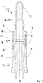
- Figure 1 shows an injection mold 100 with a multi-part core insert 1 rotationally symmetrical about a longitudinal axis 10, a neck ring 60 and a cavity insert 70 have a cylindrical structure.
- the fastening element 40 has an opening in the axial direction. However, the diameter of the opening varies in the axial direction in order to ensure a positive connection both with the upper core part 30 and with the lower core part 20.
- the lower core part 20 has an end section 21 protruding from the end face 26 in the axial direction, with two threaded bores 25 being embedded in the end section 21, which are used to fasten the fastening element 40 to the lower core part 20.
- the threaded bores 25 are arranged at an acute angle with respect to the longitudinal axis 10.
- the upper core part 30 is fixed to the lower core part 20 with the aid of the fastening element 40.
- the opening of the fastening element 40 at an end facing the lower core part 20 has a diameter such that the protruding end section 21 of the lower core part 20 can be received in a form-fitting manner.
- the fastening element 40 and the lower core insert 20 have two mutually perpendicular contact surface sections 27, 28, 47, 48, the contact surface sections 28, 48 being arranged parallel to the longitudinal axis 10 of the fastening element 40.
- the outer diameters of the lower core part 20 and of the fastening element 40 are selected so that their outer surfaces are flush.
- the opening of the fastening element 40 is also designed in such a way that the upper core part 30 can be received in the opening is.
- the upper core part 30 and the opening of the fastening element 40 have mutually corresponding stop surfaces 31, 42 which are conical in shape.
- a firm connection between the fastening element 40 and the upper core part 30 is achieved through the combination of mutually perpendicular contact surface sections and conical contact surfaces 31, 42. The same applies to the connection between the fastening element 40 and the lower core part 20, so that overall tilting of the upper core part 30 relative to the lower core part 20 is prevented.
- the multi-part core insert 1 has a cooling system.
- a cooling system for this purpose, there is a through-hole in the lower core part 20, in which a cooling liquid is guided.
- the upper core part 30 has a blind hole for guiding cooling liquid, the diameter of which corresponds to the diameter of the through hole of the lower core part 20.
- the upper core part 30 is arranged on the lower core part 20 in such a way that only two possible positions exist for the arrangement of the fastening element 40, the bores of the upper and lower core parts 20, 30 for guidance the coolant in any case flush with each other.
- the injection mold 100 has a mold space 80, the contour of which corresponds to the contour of the preform to be produced.
- the upper core insert 30 and the cavity insert 70 each have shape-forming sections 32, 71 which form part of the contour of the mold space 80.
- the other part of the mold space 80 is formed by a shape-forming section 61 of the neck ring 60, the shape-forming section 61 of the neck ring 60 being designed in such a way that a thread of a preform is formed.
- the neck ring has contact surfaces 63 which correspond to a frustoconical recess 45 of the fastening element 40 on an end 46 of the fastening element 40 facing away from the lower core part 20, so that the contact surfaces 63 of the neck ring 60 and the outer surface of the frustoconical recess 45 of the fastening element 40 are positively engaged with one another.
- the Neck ring 60 has contact surfaces 62 which are parallel to the longitudinal axis 10 and are in contact with the upper core part 30. As a result, the upper core insert 30 is additionally stabilized again.
- the cavity insert 70 has a gate 72 through which the plasticized melt is injected into the mold space 80 during the injection molding process, whereby a preform is formed.
- the cavity insert 70 and the neck ring 60 are removed by moving the components away from the multi-part core insert 1 in the axial direction.
- the preform initially remains on the core insert as in FIG Figure 2 shown.
- blow-out air is blown through blow-out channels 23, 24, 43, 44, which exerts a force on the preform parallel to the longitudinal axis 10, so that the preform is released from the upper core part 30.
- the blow-out channel 23 and the blow-out channel 24 of the lower core part 20 are arranged on opposite sides of the lower core part 20.
- the two blow-out channels 43, 44 of the fastening element 40 are directly connected to the blow-out channels 23, 24 of the lower core part 20 and are arranged between the through bores 49.
- the blow-out channels 43 and 44 of the fastening element 40 open into the recess 45 of the fastening element 40, which is located at an end 46 of the fastening element 40 facing away from the lower core part 20.
- the recess 45 is frustoconical.
- the openings of the blow-out channels 23, 24, 43, 44 lie directly one above the other in the direction of the longitudinal axis 10.
- the defined positioning is achieved by a locking pin 50.
- the material of the upper core part 30, the cavity insert 70 and the neck ring 60 is selected such that it has a particularly high thermal conductivity in order to cool the preform as quickly as possible.
- the sections of these components that form the mold space 80 are coated with a coating that makes it easier to detach the preform from the injection mold 100.
- the fastening element 40 and the lower core part 20, on the other hand, are made of a particularly robust steel that withstands the forces acting particularly well.
- Figure 3 shows an embodiment of a multi-part core insert 1, in which a different fastening mechanism for the fastening element 40 on the lower core part 20 has been selected.
- the reception of the upper core part 30 in the fastening element 40 can be configured as described above.
- an L-shaped recess 29 is arranged in the end section 21.
- the fastening element 40 also has a projection on the inner surface delimiting the recess in the radial direction, which protrudes into the L-shaped recess 29 when the fastening element 40 is pushed onto the lower core part 20 in the axial direction.
- the projection moves into the section of the L-shaped recess 29 aligned perpendicular to the longitudinal axis 10 and causes the fastening element 40 and the lower core part 20 to be clamped against one another.
Landscapes
- Engineering & Computer Science (AREA)
- Manufacturing & Machinery (AREA)
- Mechanical Engineering (AREA)
- Moulds For Moulding Plastics Or The Like (AREA)
- Injection Moulding Of Plastics Or The Like (AREA)
Abstract
Die vorliegende Erfindung betrifft einen mehrteiligen Kerneinsatz (1) für eine Spritzgießform (100) zur Herstellung von Vorformlingen aufweisend einen zweiteiligen Kern mit einer Längsachse (10), wobei der zweiteilige Kern ein unteres Kernteil (20) und ein in Richtung der Längsachse neben dem unteren Kernteil (20) angeordnetes oberes Kernteil (30) aufweist und ein Befestigungselement (40), wobei das Befestigungselement (40) eine Öffnung parallel zu der Längsachse (10) zur Aufnahme des oberen Kernteils (30) aufweist, und wobei mit dem Befestigungselement (40) das obere Kernteil (30) an einem Ende (22) des unteren Kernteils (20) befestigbar ist. Um einen Kerneinsatz für eine Spritzgießform bereitzustellen, dessen formgebender Abschnitt sich einfach und schnell auswechseln lässt, wobei gleichzeitig die Qualität und Funktionalität des Spritzgussvorgangs gewährleistet wird, wird erfindungsgemäß vorgeschlagen, dass das Befestigungselement (40) und oberes Kernteil (30) derart ausgebildet sind, dass, wenn das obere Kernteil (30) in der Öffnung aufgenommen ist zumindest in axialer Richtung eine form- und/oder kraftschlüssige Verbindung zwischen dem im Befestigungselement (40) aufgenommenen oberen Kernteil (30) und dem Befestigungselement (40) herstellbar ist und dass das Befestigungselement (40) und das untere Kernteil (20) derart ausgestaltet sind, dass das Befestigungselement (40) nur in einer Position oder in mehreren Positionen, die sich durch eine Drehung des Befestigungselementes (40) relativ zum unteren Kernteil (20) um die Längsachse (10) unterscheiden, am unteren Kernteil befestigt werden kann, wobei nur eine endliche Anzahl von Positionen, vorzugsweise maximal vier Positionen, des Befestigungselements (40) relativ zu dem unteren Kernteil (20) möglich sind.The present invention relates to a multi-part core insert (1) for an injection mold (100) for the production of preforms, comprising a two-part core with a longitudinal axis (10), the two-part core having a lower core part (20) and one in the direction of the longitudinal axis next to the lower one Core part (20) arranged upper core part (30) and a fastening element (40), wherein the fastening element (40) has an opening parallel to the longitudinal axis (10) for receiving the upper core part (30), and wherein with the fastening element (40 ) the upper core part (30) can be fastened to one end (22) of the lower core part (20). In order to provide a core insert for an injection mold whose shaping section can be exchanged easily and quickly, while at the same time ensuring the quality and functionality of the injection molding process, it is proposed according to the invention that the fastening element (40) and upper core part (30) are designed in such a way that when the upper core part (30) is received in the opening, at least in the axial direction, a positive and / or non-positive connection between the upper core part (30) received in the fastening element (40) and the fastening element (40) can be produced and that the fastening element (40) and the lower core part (20) are designed in such a way that the fastening element (40) is only in one position or in several positions, which are changed by rotating the fastening element (40) relative to the lower core part (20) about the longitudinal axis ( 10) can be attached to the lower core part, with only a finite number of positions, preferably a maximum of four positions, of the fastening element (40) relative to the lower core part (20) are possible.
Description
Die vorliegende Erfindung betrifft einen mehrteiligen Kerneinsatz für eine Spritzgießform zur Herstellung von Vorformlingen aufweisend einen zweiteiligen Kern mit einer Längsachse, wobei der zweiteilige Kern ein unteres Kernteil und ein in Richtung der Längsachse neben dem unteren Kernteil angeordnetes oberes Kernteil aufweist, und ein Befestigungselement, wobei das Befestigungselement im Wesentlichen hohlzylindrisch ausgebildet ist und eine Längsachse aufweist, wobei das Befestigungselement eine Öffnung parallel zu der Längsachse zur Aufnahme des oberen Kernteils aufweist, und wobei mit dem Befestigungselement das obere Kernteil an einem Ende des unteren Kernteils befestigbar ist.The present invention relates to a multi-part core insert for an injection mold for the production of preforms, comprising a two-part core with a longitudinal axis, the two-part core having a lower core part and an upper core part arranged in the direction of the longitudinal axis next to the lower core part, and a fastening element, the Fastening element is essentially hollow-cylindrical and has a longitudinal axis, the fastening element having an opening parallel to the longitudinal axis for receiving the upper core part, and wherein the upper core part can be fastened to one end of the lower core part with the fastening element.
Derartige Kerneinsätze werden vor allem in Spritzgießformen für das Spritzgießen von Vorformlingen verwendet. Solche Vorformlinge können z.B. PET-Vorformlinge sein, die in einem weiteren Bearbeitungsschritt zu PET-Flaschen aufgeblasen werden. Um einen Vorformling herzustellen, wird ein aus einem Kunststoff bestehendes Granulat plastifiziert, d.h. aufgeschmolzen und homogenisiert. Anschließend wird unter hohem Druck die plastifizierte Schmelze in einen Formraum der Spritzgießform eingespritzt.Such core inserts are mainly used in injection molds for the injection molding of preforms. Such preforms can, for example, be PET preforms which are blown into PET bottles in a further processing step. In order to produce a preform, a granulate made of plastic is plasticized, i.e. melted and homogenized. The plasticized melt is then injected into a mold space of the injection mold under high pressure.
Ein Teil dieses Formraums und damit ein Teil der Form des Vorformlings wird von der Außenkontur des Kerneinsatzes bestimmt, nämlich der innere Teil bzw. die Innenfläche des herzustellenden Vorformlings.Part of this mold space and thus part of the shape of the preform is determined by the outer contour of the core insert, namely the inner part or the inner surface of the preform to be produced.
Die plastifizierte Schmelze bleibt nach dem Einspritzen solange im Formraum, bis diese sich soweit abgekühlt hat, dass der Vorformling stabil ist und entnommen werden kann. Um ein schnelles Abkühlen der plastifizierten Schmelze zu gewährleisten, weist der Kerneinsatz häufig ein Kühlsystem auf, das den Vorformling an dessen Innenseite abkühlt. Zu diesem Zweck ist in dem Inneren des Kerneinsatzes ein Kanalsystem ausgebildet, durch welches eine Kühlflüssigkeit geführt wird.After the injection, the plasticized melt remains in the mold space until it has cooled down enough that the preform is stable and can be removed. In order to ensure rapid cooling of the plasticized melt, the core insert often has a cooling system that cools the inside of the preform. For this purpose, a channel system is formed in the interior of the core insert, through which a cooling liquid is guided.
Diejenigen Flächen des Kerneinsatzes, die mit der plastifizierten Schmelze in Kontakt treten, unterliegen einem erhöhten Verschleiß. Dies liegt im Wesentlichen daran, dass sie aufgrund des Spritzgießvorgangs wiederholt großen Druck- und Temperaturschwankungen ausgesetzt sind.Those surfaces of the core insert that come into contact with the plasticized melt are subject to increased wear. This is mainly due to the fact that they are repeatedly exposed to large pressure and temperature fluctuations due to the injection molding process.
In der Regel sind Kerneinsätze derartiger Spritzgießformen einteilig ausgestaltet. In diesem Fall muss der komplette Kerneinsatz ausgetauscht werden, wenn die Außenkontur eines Kerneinsatzes verschlissen ist. Nicht selten werden die beschriebenen Spritzgießformen auch zum Herstellen von Vorformlingen mit verschiedenen Konturen verwendet. Um die Kontur eines Vorformlings zu ändern, muss zumindest der formgebende Teil des Kerneinsatzes ausgetauscht werden. Bei einteiligen Kerneinsätzen bedeutet dies jedoch ebenfalls den vollständigen Austausch des Kerneinsatzes. Das vollständige Austauschen der Kerneinsätze ist allerdings sowohl material- als auch zeitintensiv.As a rule, core inserts of such injection molds are designed in one piece. In this case, the entire core insert must be replaced when the outer contour of a core insert is worn out. It is not uncommon for the injection molds described to be used to produce preforms with different contours. In order to change the contour of a preform, at least the shaping part of the core insert has to be replaced. In the case of one-piece core inserts, however, this also means the complete replacement of the core insert. However, the complete replacement of the core inserts is both material and time-consuming.
Aus dem Stand der Technik sind daher Kerneinsätze bekannt, die einen zweiteiligen Kerneinsatz bereitstellen, wobei lediglich ein Teil des Kerneinsatzes zu der Form des Vorformlings beiträgt und damit erhöhtem Verschleiß ausgesetzt ist. Bei derartigen Kerneinsätzen ist es ausreichend, wenn lediglich der entsprechende Teil des Kerneinsatzes ausgetauscht wird, wenn dieser verschlissen ist oder wenn eine andere Form von Vorformlingen hergestellt werden soll. Auf diese Weise kann Material eingespart werden.Core inserts are therefore known from the prior art which provide a two-part core insert, only part of the core insert contributing to the shape of the preform and thus being exposed to increased wear. In the case of core inserts of this type, it is sufficient if only the corresponding part of the core insert is exchanged if it is worn out or if a different shape of preforms is to be produced. In this way, material can be saved.
Bei derartigen zweiteiligen Kerneinsätzen muss jedoch sichergestellt werden, dass beide Teile des Kerneinsatzes zuverlässig miteinander verbunden sind, um den Ausschuss bei der Produktion der Vorformlinge zu minimieren. Sind die Teile nicht zuverlässig miteinander verbunden und der Teil, welcher zu der Form des Vorformlings beiträgt, kann sich während dem Einspritzvorgang bewegen, indem er beispielsweise eine Kippbewegung relativ zu dem anderen Teil des Kerneinsatzes vollführt, führt dies zu einer ungewollten und unkalkulierbaren Veränderung des Formraums, in welchem der Vorformling hergestellt wird. Derartige unkontrollierbare Veränderungen des Formraums führen mindestens zu veränderten Wandstärken des Vorformlings, die im schlimmsten Fall zu einer Unverwertbarkeit des Vorformlings führen. Zudem besteht die Gefahr, dass Kühlflüssigkeit zwischen unterem und oberem Kernteil austritt.In the case of such two-part core inserts, however, it must be ensured that both parts of the core insert are reliably connected to one another in order to minimize rejects during the production of the preforms. If the parts are not reliably connected to one another and the part that contributes to the shape of the preform can move during the injection process, for example by performing a tilting movement relative to the other part of the core insert, this leads to an undesired and incalculable change in the mold space in which the preform is made. Such uncontrollable changes in the mold space lead at least to changed wall thicknesses of the preform, which in the worst case lead to the preform being unusable. In addition, there is a risk that coolant will leak between the lower and upper core part.
Aus der
Hierbei hat es sich jedoch als nachteilig erwiesen, dass zur Auswechslung des vorderen Kernteils dennoch der vollständige Kerneinsatz demontiert werden muss, da der Stützring an der Basisplatte befestigt ist, auf welcher der gesamte Kerneinsatz montiert ist. Die Auswechselung des Kerneinsatzes ist damit sehr zeitintensiv.In this case, however, it has proven to be disadvantageous that the complete core insert still has to be dismantled in order to replace the front core part, since the support ring is on the base plate is attached, on which the entire core insert is mounted. Changing the core insert is therefore very time-consuming.
Da bei der Produktion von Vorformlingen im Spritzgussverfahren eine möglichst große Anzahl von Vorformlingen in möglichst geringer Zeit gefertigt werden soll, ist ein Ausfall der Anlage aufgrund von Austauscharbeiten an den Kerneinsätzen vorteilhafterweise so gering wie möglich zu halten.Since the largest possible number of preforms should be manufactured in the shortest possible time in the production of preforms by injection molding, a failure of the system due to replacement work on the core inserts is advantageously to be kept as low as possible.
Ausgehend von dem beschriebenen Stand der Technik ist es daher Aufgabe der vorliegenden Erfindung, einen Kerneinsatz für eine Spritzgießform bereitzustellen, dessen formgebender Abschnitt sich einfach und schnell auswechseln lässt, wobei gleichzeitig die Qualität und Funktionalität des Spritzgussvorgangs gewährleistet wird.Based on the described prior art, it is therefore the object of the present invention to provide a core insert for an injection mold, the shaping section of which can be exchanged easily and quickly, while at the same time ensuring the quality and functionality of the injection molding process.
Diese Aufgabe wird erfindungsgemäß durch einen mehrteiligen Kerneinsatz wie oben beschrieben gelöst, bei dem Befestigungselement und oberes Kernteil derart ausgebildet sind, dass, wenn das oberer Kernteil in der Öffnung aufgenommen ist, zumindest in axialer Richtung eine form- und/oder kraftschlüssige Verbindung zwischen dem im Befestigungselement aufgenommenen oberen Kernteil und dem Befestigungselement herstellbar ist, und bei dem das Befestigungselement und der untere Kernteil derart ausgestaltet sind, dass das Befestigungselement nur in einer Position oder in mehreren Positionen, die sich durch eine Drehung des Befestigungselementes relativ zum unteren Kernteil um die Längsachse unterscheiden, am unteren Kernteil befestigt werden kann, wobei nur eine endliche Anzahl von Positionen, vorzugsweise maximal vier Positionen des Befestigungselementes relativ zu dem unteren Kernteil möglich sind.This object is achieved according to the invention by a multi-part core insert as described above, in which the fastening element and the upper core part are designed in such a way that, when the upper core part is received in the opening, a form-fitting and / or force-fitting connection between the im Fastening element received upper core part and the fastening element can be produced, and in which the fastening element and the lower core part are designed such that the fastening element only in one position or in several positions that differ by a rotation of the fastening element relative to the lower core part about the longitudinal axis , can be attached to the lower core part, with only a finite number of positions, preferably a maximum of four positions, of the fastening element relative to the lower core part are possible.
Der Vorteil des erfindungsgemäßen Befestigungselements besteht darin, dass hiermit das obere Kernteil direkt an dem unteren Kernteil befestigt wird, unabhängig von der Befestigung des unteren Kernteiles an einer Basisplatte. Somit kann das obere Kernteil besonders einfach ausgewechselt werden, indem lediglich das Befestigungselement von dem unteren Kernteil gelöst werden muss, welcher leichter zugänglich ist als eine Basisplatte, auf welcher häufig mehrere Kerneinsätze unmittelbar nebeneinander angeordnet sind. Die Ausfallzeiten einer Spritzgießanlage aufgrund von Umbauarbeiten werden damit minimiert.The advantage of the fastening element according to the invention is that it is used to fasten the upper core part directly to the lower core part, independently of the fastening of the lower core part to a base plate. Thus, the upper core part can be exchanged particularly easily, in that only the fastening element has to be detached from the lower core part, which is more easily accessible than a base plate on which several core inserts are often arranged directly next to one another. The downtimes of an injection molding system due to conversion work are thus minimized.
Das Befestigungselement ist derart ausgestaltet, dass das obere Kernteil in dem Befestigungselement aufnehmbar ist. Zu diesem Zweck weist das Befestigungselement eine Durchgangsöffnung auf, so dass das Befestigungselement eine im Wesentlichen hohlzylindrische Form aufweist. Die Durchgangsöffnung erstreckt sich parallel zu der Längsachse. Durchgangsöffnungen, die sich entlang der Längsachse erstrecken, gelten ebenfalls als parallel zu der Längsachse ausgerichtet. In die Durchgangsöffnung kann das obere Kernteil des Kerneinsatzes aufgenommen werden.The fastening element is designed in such a way that the upper core part can be received in the fastening element. For this purpose, the fastening element has a through opening, so that the fastening element has an essentially hollow-cylindrical shape. The through opening extends parallel to the longitudinal axis. Through openings that extend along the longitudinal axis are also considered to be aligned parallel to the longitudinal axis. The upper core part of the core insert can be received in the through opening.
Das obere und das untere Kernteil weisen ebenfalls einen im Wesentlichen zylindrischen Querschnitt auf. Der Begriff "im Wesentlichen zylindrisch" bzw. "im Wesentlichen hohlzylindrisch" bezieht sich nicht ausschließlich auf exakt runde Formen. Vielmehr sind auch Kerneinsätze mit anderen Querschnittsformen, beispielsweise Quadrate, Sechs- oder andere Vielecke denkbar. Die Querschnittsform der Öffnung des Befestigungselements muss lediglich an die Querschnittsform des oberen Kernteils angepasst sein.The upper and lower core parts also have a substantially cylindrical cross section. The term “essentially cylindrical” or “essentially hollow cylindrical” does not exclusively refer to exactly round shapes. Rather, core inserts with other cross-sectional shapes, for example squares, hexagons or other polygons, are also conceivable. The cross-sectional shape of the opening of the fastening element only has to be adapted to the cross-sectional shape of the upper core part.
Dadurch, dass das Befestigungselement nur in einer Position oder nur in einer begrenzten Anzahl von Positionen, die sich lediglich durch eine Relativdrehung des Befestigungselementes gegenüber dem unteren Kernteil unterscheiden, kann das Befestigungselement weitere Funktionen, wie z.B. das Bereitstellen eines Fluidkanals oder das Bereitstellen einer Halterung für z.B. einen Sensor, erfüllen. In jedem Fall kann das Befestigungselement nur in vorbestimmten Positionen an dem unteren Kernteil befestigt werden.Because the fastening element is only in one position or only in a limited number of positions, which differ only in a relative rotation of the fastening element with respect to the lower core part, the fastening element can perform other functions, such as providing a fluid channel or providing a holder for e.g. a sensor. In any case, the fastening element can only be fastened to the lower core part in predetermined positions.
Um das obere Kernteil in dem Befestigungselement aufzunehmen, ist der mehrteilige Kerneinsatz in einer Ausführungsform derart ausgestaltet, dass das obere Kernteil und die Öffnung des Befestigungselements zueinander korrespondierende Anschlagsflächen aufweisen, wobei die Anschlagsflächen vorzugweise derart ausgebildet sind, dass eine axiale Relativbewegung des Befestigungselements gegenüber dem oberen Kernteil in Richtung des dem unteren Kernteil zugewandten Teils des oberen Kernteils und/oder eine radiale Relativbewegung zwischen Befestigungselement und oberem Kernteil begrenzt wird.To accommodate the upper core part in the fastening element, the multi-part core insert is designed in one embodiment such that the upper core part and the opening of the fastening element have mutually corresponding stop surfaces, the stop surfaces preferably being designed such that an axial relative movement of the fastening element with respect to the upper Core part in the direction of the lower core part facing part of the upper core part and / or a radial relative movement between the fastening element and the upper core part is limited.
Vorzugsweise kann das Befestigungselement nur von einer Seite des oberen Kernteiles auf dieses aufgesetzt werden, um den erfindungsgemäßen mehrteiligen Kerneinsatz zusammenzusetzen. An ein dem unteren Kernteil zugewandten Ende des oberen Kernteiles kann der Durchmesser desselben größer als ein Durchmesser der Öffnung des Befestigungselementes sein, sodass es nicht möglich ist, das obere Kernteil durch das Befestigungselement vollständig hindurchzuführen.Preferably, the fastening element can only be placed on one side of the upper core part in order to assemble the multi-part core insert according to the invention. At an end of the upper core part facing the lower core part, the diameter of the upper core part can be greater than a diameter of the opening of the fastening element, so that it is not possible to lead the upper core part completely through the fastening element.
In einer weiteren Ausführungsform des mehrteiligen Kerneinsatzes sind die korrespondierenden Anschlagsflächen der Öffnung des Befestigungselementes und des oberen Kernteiles konisch ausgestaltet. Eine konische Fläche ist ein Abschnitt auf einer Außenfläche (Mantelfläche) eines Kegelstumpfes oder eines Kegels. So kann auf das obere Kernteil besonders effektiv eine Haltekraft in einer Richtung parallel zu der Längsachse ausgeübt werden.In a further embodiment of the multi-part core insert, the corresponding stop surfaces of the opening of the fastening element and of the upper core part are designed conically. A conical surface is a section on an outer surface (lateral surface) of a truncated cone or a cone. In this way, a holding force can be exerted particularly effectively on the upper core part in a direction parallel to the longitudinal axis.
In einer weiteren Ausführungsform ist der Konus derart ausgestaltet, dass sein Außendurchmesser in Richtung des unteren Kernteils größer wird.In a further embodiment, the cone is designed in such a way that its outer diameter increases in the direction of the lower core part.
Alternativ können in einer weiteren Ausführungsform des mehrteiligen Kerneinsatzes die korrespondierenden Anschlagsflächen zwei zueinander winklig angeordnete, vorzugsweise zueinander senkrecht stehende Anschlagsflächenabschnitte aufweisen, wobei vorzugsweise jeweils einer der Kontaktflächenabschnitte parallel zu der Längsachse des Befestigungselements ist. Eine Kombination mit einer konischen Anschlagsfläche ist jedoch auch denkbar.Alternatively, in a further embodiment of the multi-part core insert, the corresponding stop surfaces can have two stop surface sections arranged at an angle to one another, preferably perpendicular to one another, with one of the contact surface sections preferably being parallel to the longitudinal axis of the fastening element. However, a combination with a conical stop surface is also conceivable.
In einer weiteren Ausführungsform des mehrteiligen Kerneinsatzes ist das erfindungsgemäße Befestigungselement derart ausgestaltet, dass die Anschlagsfläche des Befestigungselements und die Anschlagsfläche des oberen Kernteils mit einer Spielpassung aufeinander angepasst sind. Die Spielpassung der beiden Anschlagsflächen führt dazu, dass das obere Kernteil auch in einem zusammengesetzten Zustand des mehrteiligen Kerneinsatzes schwimmend in dem Befestigungselement gelagert ist. Spielpassung bedeutet in diesem Fall, dass die Anschlagsflächen zumindest in radialer Richtung nicht oder nicht vollumfänglich miteinander in Kontakt stehen, sondern ein Spalt von beispielsweise wenigen Mikrometern besteht.In a further embodiment of the multi-part core insert, the fastening element according to the invention is designed such that the stop surface of the fastening element and the stop surface of the upper core part are adapted to one another with a loose fit. The clearance fit of the two stop surfaces means that the upper core part is also floatingly supported in the fastening element when the multi-part core insert is in an assembled state. In this case, a clearance fit means that the stop surfaces are not in contact with one another or not in full circumference, at least in the radial direction, but that there is a gap of, for example, a few micrometers.
Dies bietet den Vorteil, dass wenn der mehrteilige Kerneinsatz in einer Spritzgießform zusammengesetzt wird, indem ein sogenannter Kavitäteneinsatz über das obere Kernteil gestülpt wird, weniger Verschleiß an dem oberen Kernteil entsteht, da das obere Kernteil gegenüber dem Kavitäteneinsatz leicht verschoben werden kann. Durch das Spiel wird auch der Verschleiß an dem Befestigungselement reduziert, in welches der Kavitäteneinsatz eingreift, um eine stabile Verbindung zwischen dem Kerneinsatz und dem Kavitäteneinsatz zu erzielen.This offers the advantage that if the multi-part core insert is put together in an injection mold by placing a so-called cavity insert over the upper core part, less wear and tear occurs on the upper core part, since the upper core part can be easily displaced relative to the cavity insert. The play also reduces the wear on the fastening element in which the cavity insert engages in order to achieve a stable connection between the core insert and the cavity insert.
Das in dem Befestigungselement aufgenommene obere Kernteil wird durch das Befestigungselement in einem zusammengesetzten Zustand des mehrteiligen Kerneinsatzes an dem unteren Kernteil befestigt.The upper core part received in the fastening element is fastened to the lower core part by the fastening element in an assembled state of the multi-part core insert.
In dem zusammengesetzten Zustand des mehrteiligen Kerneinsatzes sind die Längsachsen des oberen und unteren Kernteils sowie des Befestigungselements parallel zueinander. Vorzugsweise haben alle drei Komponenten eine gemeinsame zentrale Längsachse, welche eine Rotationssymmetrie des mehrteiligen Kerneinsatzes beschreibt.In the assembled state of the multi-part core insert, the longitudinal axes of the upper and lower core parts and of the fastening element are parallel to one another. All three components preferably have a common central longitudinal axis, which describes a rotational symmetry of the multi-part core insert.
Weiterhin vorzugsweise berühren sich die einander zugewandten Endflächen des oberen und unteren Kernteils. Dabei ist es besonders bevorzugt, dass die beiden Endflächen bündig aneinander anschließen. Beispielsweise könnten beide Endflächen den gleichen Innen- und/oder Außendurchmesser aufweisen.Furthermore, the mutually facing end surfaces of the upper and lower core parts preferably touch one another. It is particularly preferred that the two end faces are flush with one another. For example, both end faces could have the same inside and / or outside diameter.
Ein Teil einer Außenkontur des oberen Kernteiles trägt zu der Innenform des herzustellenden Vorformlings bei, während das untere Kernteil nicht zu der Form des Vorformlings beiträgt und primär der Befestigung des Kerneinsatzes an einer Basisplatte, also einer Werkzeughalterung, sowie der Zuführung und Abführung von Kühlflüssigkeit dient.Part of an outer contour of the upper core part contributes to the inner shape of the preform to be produced, while the lower core part does not primarily contribute to the shape of the preform the attachment of the core insert to a base plate, i.e. a tool holder, as well as the supply and discharge of coolant is used.
Um einen Vorformling effektiv abzukühlen, ist es sinnvoll, die formgebende Außenkontur des oberen Kernteils durch eine permanente Wasserzu- und abfuhr zu kühlen. Zu diesem Zweck befindet sich in dem unteren Kernteil eine Durchgangsbohrung und in dem oberen Kernteil eine mit der Bohrung im unteren Kernteil korrespondierende Sackbohrung. Vorzugsweise sind die Bohrungen in dem unteren und oberen Kernteil derart ausgestaltet, dass deren Querschnitt im Wesentlichen identisch ist, um ungewollte Verwirbelungen der Kühlflüssigkeit zu vermeiden.In order to effectively cool a preform, it makes sense to cool the shaping outer contour of the upper core part by means of permanent water supply and drainage. For this purpose there is a through hole in the lower core part and a blind hole corresponding to the hole in the lower core part in the upper core part. The bores in the lower and upper core part are preferably designed in such a way that their cross-section is essentially identical in order to avoid unwanted turbulence in the cooling liquid.
Im zusammengesetzten Zustand des mehrteiligen Kerneinsatzes ist es somit möglich, dass eine Kühlflüssigkeit in dem unteren und oberen Kernteil zirkuliert. Gegebenenfalls kann hierzu ein Leitelement in sowohl das untere Kernteil als auch das oberer Kernelement eingesetzt werden.In the assembled state of the multi-part core insert, it is thus possible for a cooling liquid to circulate in the lower and upper core part. If necessary, a guide element can be inserted into both the lower core part and the upper core element for this purpose.
Des Weiterhin weist in einer weiteren Ausführungsform mindestens eine der beiden Endflächen eine Nut zur Aufnahme eines Dichtungselements, z. B. eines O-Rings auf. Befindet sich der O-Ring in der Nut und sind das untere und das obere Kernteil miteinander verbunden, dann dichtet der O-Ring die beiden Abschnitte zueinander ab, sodass keine Kühlflüssigkeit austreten kann.Furthermore, in a further embodiment, at least one of the two end faces has a groove for receiving a sealing element, e.g. B. an O-ring. If the O-ring is in the groove and the lower and upper core parts are connected to one another, then the O-ring seals the two sections against one another so that no coolant can escape.
Um ungewollte Verwirbelungen der Kühlflüssigkeit zusätzlich zu vermeiden, ist es wichtig zu gewährleisten, dass die beiden Kernteile möglichst passgenau aneinandergefügt werden. Dies ist insbesondere in solchen Fällen relevant, in welchem sich die Bohrungen für die Kühlflüssigkeit nicht gleichmäßig um die zentrale Längsachse des mehrteiligen Kerneinsatzes erstrecken. Zu diesem Zweck sind in einer Ausführungsform das Befestigungselement, das obere Kernteil und das untere Kernteil so ausgestaltet, dass nur eine endliche Anzahl von Positionen des oberen Kernteils relativ zu dem unteren Kernteil möglich ist. Mit anderen Worten, das erfindungsgemäße Befestigungselement erlaubt, das obere Kernteil nur in bestimmten Winkelpositionen an dem unteren Kernteil zu befestigen, sodass bei jeder Position gewährleistet ist, dass die Bohrungen für die Kühlflüssigkeit im oberen und unteren Kernteil bündig aneinander anschließen.In order to additionally avoid unwanted turbulence in the coolant, it is important to ensure that the two core parts are joined together as precisely as possible. This is particularly relevant in those cases in which the bores for the cooling liquid do not extend uniformly around the central longitudinal axis of the multi-part core insert. For this purpose, in one embodiment, the fastening element, the upper core part and the lower core part are designed such that only a finite number of positions of the upper core part relative to the lower core part is possible. In other words, the fastening element according to the invention allows the upper core part to be fastened to the lower core part only in certain angular positions, so that in every position it is ensured that the bores for the cooling liquid in the upper and lower core part are flush with one another.
Um dies zu gewährleisten, kann das Befestigungselement und/oder das untere Kernteil in einer Ausführungsform an einer bestimmten Position auf der Endfläche, die der jeweils anderen Komponente zugewandt ist, einen Vorsprung bzw. eine Vertiefung aufweisen, in welche der Vorsprung, beispielsweise ein Arretierstift, eingreift, wenn der mehrteilige Kerneinsatz zusammengesetzt wird. Damit existiert nur eine Position, in welcher das Befestigungselement relativ zu dem unteren Kernteil befestigt wird.In order to ensure this, the fastening element and / or the lower core part can in one embodiment have a projection or a recess into which the projection, for example a locking pin, engages when the multi-part core insert is assembled. There is thus only one position in which the fastening element is fastened relative to the lower core part.
Um das Befestigungselement und den unteren Kerneinsatz zuverlässig miteinander zu verbinden, weist der mehrteilige Kerneinsatz in einer Ausführungsform eine solche Ausgestaltung auf, dass das untere Kernteil und das Befestigungselement zueinander korrespondierende Kontaktflächen aufweisen, die in einem zusammengesetzten Zustand des mehrteiligen Kerneinsatzes miteinander in Kontakt stehen.In order to reliably connect the fastening element and the lower core insert to one another, the multi-part core insert in one embodiment has a configuration such that the lower core part and the fastening element have mutually corresponding contact surfaces which are in contact with one another in an assembled state of the multi-part core insert.
In einer weiteren Ausführungsform des mehrteiligen Kerneinsatzes sind die zueinander korrespondierenden Kontaktflächen des unteren Kernteils und des Befestigungselementes mit zwei zueinander winklig, vorzugsweise senkrecht, stehenden Kontaktflächenabschnitten ausgestattet, wobei vorzugsweise jeweils einer der Kontaktflächenabschnitte des unteren Kernteiles und des Befestigungselements parallel zu der Längsachse des Befestigungselementes ausgerichtet ist. Durch die zwei zueinander winklig stehenden Kontaktflächenabschnitte werden eine bessere Halterung des Befestigungselements und damit eine bessere Fixierung zwischen dem oberen und dem unterem Kernteil ermöglicht. Diese Kontaktflächen bewirken darüber hinaus, dass ein Verkippen der beiden Abschnitte relativ zueinander während des Spritzgießvorgangs verhindert wird. Gleiches gilt für die in einer Ausführungsform winklig zueinander stehenden Anschlagsflächen zwischen oberem Kernteil und Befestigungselement.In a further embodiment of the multi-part core insert, the mutually corresponding contact surfaces of the lower core part and the fastening element are equipped with two contact surface sections at an angle to one another, preferably perpendicular, one of the contact surface sections of the lower core part and the fastening element preferably being aligned parallel to the longitudinal axis of the fastening element . The two contact surface sections at an angle to one another enable better holding of the fastening element and thus better fixation between the upper and lower core parts. These contact surfaces also have the effect that the two sections are prevented from tilting relative to one another during the injection molding process. The same applies to the stop surfaces between the upper core part and the fastening element, which are at an angle to one another in one embodiment.
In einer Ausführungsform ist der mehrteilige Kerneinsatz derart ausgestaltet, dass an einem der zur Längsachse parallelen Kontaktflächenabschnitte des unteren Kernteils oder des Befestigungselementes mindestens ein Vorsprung, vorzugsweise mindestens zwei Vorsprünge, in radialer Richtung ausgebildet sind und wobei an dem korrespondierenden zur Längsachse parallelen Kontaktflächenabschnitt des unteren Kernteils oder des Befestigungselements eine im Wesentlichen L-förmige Ausnehmung vorgesehen ist, in welcher der Vorsprung der korrespondierenden Kontaktfläche in einem zusammengesetzten Zustand des mehrteiligen Kerneinsatzes eingreift.In one embodiment, the multi-part core insert is designed in such a way that at least one projection, preferably at least two projections, are formed in the radial direction on one of the contact surface sections of the lower core part or the fastening element parallel to the longitudinal axis, and on the corresponding contact surface section of the lower core part that is parallel to the longitudinal axis or a substantially L-shaped recess is provided in the fastening element, in which the projection of the corresponding contact surface engages in an assembled state of the multi-part core insert.
Das untere Kernteil und das Befestigungselement werden durch Ineinanderstecken entlang der Längsachse und entgegengesetztes Drehen um die Längsachse, vorzugsweise um etwa 20° bis 50°, verbunden und so auch wieder getrennt. Diese nach dem Prinzip eines Bajonettverschlusses wirkende Verbindung führt zu einer form- und/oder kraftschlüssigen Verbindung zwischen dem Befestigungselement und dem unteren Kernteil.The lower core part and the fastening element are connected by plugging into one another along the longitudinal axis and rotating in the opposite direction around the longitudinal axis, preferably by about 20 ° to 50 °, and thus also separated again. This connection, acting on the principle of a bayonet lock, leads to a form-fitting and / or force-fitting connection between the fastening element and the lower core part.
Die Vorsprünge können entweder an den Kontaktflächen des Befestigungselements oder an den Kontaktflächen des unteren Kernteiles angeordnet sein, wobei die L-förmige Ausnehmung in der entsprechend gegenüberliegenden Kontaktfläche angeordnet ist, sodass der Vorsprung in die Ausnehmung eingreift.The projections can be arranged either on the contact surfaces of the fastening element or on the contact surfaces of the lower core part, the L-shaped recess being arranged in the correspondingly opposite contact surface so that the projection engages in the recess.
Der Vorteil einer solchen bajonettverschlussartigen Verbindung besteht darin, dass so der obere Kernteil besonders einfach von dem unteren Kernteil gelöst werden kann und dass der obere Kernteil immer in bestimmten, definierten Positionen auf dem unteren Kernteil angeordnet ist, wenn der mehrteilige Kerneinsatz zusammengesetzt ist. Gleichzeitig wird durch die jeweiligen Kontaktflächenabschnitte eine zuverlässige Verbindung zwischen dem unterem Kernteil und dem Befestigungselement gewährleistet.The advantage of such a bayonet-like connection is that the upper core part can be detached particularly easily from the lower core part and that the upper core part is always arranged in certain, defined positions on the lower core part when the multi-part core insert is assembled. At the same time, the respective contact surface sections ensure a reliable connection between the lower core part and the fastening element.
In einer weiteren Ausführungsform weist das untere Kernteil an einem dem Befestigungselement zugewandten Ende einen von der Endfläche in axialer Richtung hervorstehenden Endabschnitt auf und das Befestigungselement an einem dem unteren Kernteil zugewandten Ende eine zu dem Endabschnitt des unteren Kernteils korrespondierende Vertiefung. In einem zusammengesetzten Zustand des Kerneinsatzes stehen so die Vertiefung des Befestigungselementes und der hervorstehende Endabschnitt des unteren Kernteils miteinander in Kontakt. Es versteht sich, dass umgekehrt auch das untere Kernteil an einem dem Befestigungselement zugewandten Ende eine Vertiefung aufweisen kann und das Befestigungselement an einem dem unteren Kernteil zugewandten Ende eine zu der Vertiefung des unteren Kernteils korrespondierenden hervorstehenden Endabschnitt, welche in einem zusammengesetzten Zustand wiederum in Kontakt miteinander stehen, d.h. ineinander eingreifen.In a further embodiment, the lower core part has at an end facing the fastening element an end section protruding from the end face in the axial direction and the fastening element has a recess corresponding to the end section of the lower core part at an end facing the lower core part. In an assembled state of the core insert, the recess of the fastening element and the protruding end portion of the lower core part are in contact with one another. It goes without saying that, conversely, the lower core part can also have a recess at an end facing the fastening element and the fastening element at an end facing the lower core part can have a protruding end section corresponding to the recess of the lower core part, which in turn is in contact with one another in an assembled state stand, ie interlock.
Eine solche Ausgestaltung der Verbindung zwischen dem unteren Kernteil und dem Befestigungselement ist insbesondere dann vorteilhaft, wenn der Kerneinsatz horizontal montiert wird, sodass erhöhte Hebelkräfte auf den oberen Kernteil wirken. Die beschriebene Verbindung über die Vertiefung und den hervorstehenden Endabschnitt zwischen dem unteren Kernteil und dem Befestigungselement führt in diesem Fall zu einer verbesserten Verbindung, da weder das Befestigungselement noch das obere Kernteil gegenüber dem unteren Kernteil abknicken können. Die stabile Befestigung des Kerneinsatzes ist wiederum wie eingangs beschrieben wichtig für die Qualität der produzierten Vorformlinge, da es bei Fehlpositionierungen des Kerneinsatzes zu unterschiedlichen Wandstärken des Vorformlings kommen kann oder im schlimmsten Fall zu überhaupt nicht verwendbaren Vorformlingen.Such a configuration of the connection between the lower core part and the fastening element is particularly advantageous when the core insert is mounted horizontally so that increased leverage forces act on the upper core part. The described connection via the recess and the protruding end section between the lower core part and the fastening element leads in this case to an improved connection, since neither the fastening element nor the upper core part can kink with respect to the lower core part. The stable fastening of the core insert is, in turn, as described above, important for the quality of the preforms produced, since incorrect positioning of the core insert can lead to different wall thicknesses of the preform or, in the worst case, to preforms that cannot be used at all.
In einer weiteren Ausführungsform ist das Befestigungselement in einem zusammengesetzten Zustand des mehrteiligen Kerneinsatzes derart auf dem unteren Kernteil angeordnet, dass eine Außenfläche des Befestigungselementes bündig mit einer Außenfläche des unteren Kernteils abschließt. Dies ist insbesondere vorteilhaft, da in der Praxis häufig mehrere Kerneinsätze unmittelbar nebeneinander positioniert werden, um mehrere Vorformlinge gleichzeitig produzieren zu können. Dabei ist es sinnvoll, unnötige Überstände beispielsweise durch das Befestigungselement zu vermeiden. Durch den bündigen Abschluss der Außenflächen des Befestigungselements und des unteren Kernteils können die Kerneinsätze möglichst nah aneinander positioniert werden und mehr Vorformlinge in einem Spritzgießprozess hergestellt werden.In a further embodiment, the fastening element is arranged in an assembled state of the multi-part core insert on the lower core part in such a way that an outer surface of the fastening element is flush with an outer surface of the lower core part. This is particularly advantageous since, in practice, several core inserts are often positioned directly next to one another in order to be able to produce several preforms at the same time. It makes sense to avoid unnecessary protrusions, for example through the fastening element. Due to the flush finish of the outer surfaces of the fastener and the In the lower core part, the core inserts can be positioned as close to one another as possible and more preforms can be produced in one injection molding process.
In einer weiteren Ausführungsform des mehrteiligen Kerneinsatzes ist das Befestigungselement derart ausgestaltet, dass das Befestigungselement mindestens ein Durchgangsloch im Bereich der Kontaktflächen des unteren Kernteiles und des Befestigungselements für mindestens ein Befestigungsmittel aufweist. Das untere Kernteil weist eine entsprechende Bohrung auf, in welche das mindestens eine Befestigungsmittel durch das Durchgangsloch des Befestigungselements eingeführt wird, um so eine form- und/oder kraftschlüssige Verbindung herzustellen. Unter einem Befestigungsmittel werden beispielsweise Schrauben oder Stifte aufgefasst, die in die entsprechenden Bohrungen an dem unteren Kernteil passen. Bei den Bohrungen handelt es sich vorzugsweise um Gewindebohrungen, die passend zu den Befestigungsmitteln ausgestaltet sind.In a further embodiment of the multi-part core insert, the fastening element is designed such that the fastening element has at least one through hole in the area of the contact surfaces of the lower core part and the fastening element for at least one fastening means. The lower core part has a corresponding bore into which the at least one fastening means is inserted through the through hole of the fastening element in order to produce a form-fitting and / or force-fitting connection. A fastening means includes, for example, screws or pins that fit into the corresponding bores on the lower core part. The bores are preferably threaded bores that are designed to match the fastening means.
Vorzugsweise sind die Bohrungen und die Durchgangslöcher derart in einem spitzen Winkel zu der Längsachse des Kerneinsatzes angeordnet, dass das Befestigungselement und damit auch das obere Kernteil in Richtung des unteren Kernteils gezogen wird, wenn die Befestigungsmittel durch die Durchgangslöcher in die Bohrungen eingebracht sind.The bores and the through holes are preferably arranged at an acute angle to the longitudinal axis of the core insert in such a way that the fastening element and thus also the upper core part is pulled in the direction of the lower core part when the fastening means are introduced into the bores through the through holes.
In einer weiteren Ausführungsform weisen das Befestigungselement und das untere Kernteil jeweils mindestens einen Ausblaskanal für Ausblasluft auf. Durch diese Ausblaskanäle wird nach dem Spritzgießvorgang in hauptsächlich axialer Richtung Ausblasluft gegen den abgekühlten Vorformling gepresst, sodass das Ausformen des Vorformlings erleichtert wird. Um an dieser Stelle eine möglichst hohe Kraftübertragung der Ausblasluft auf dem Vorformling zu gewährleisten, ist es vorteilhaft, wenn der Kanal des unteren Kernteils in axialer Richtung unmittelbar an den Kanal des Befestigungselements grenzt. Etwaige je nach Positionierung zufällige Umlenkungen oder Fehlpassungen der Kanäle, die den Luftstrom um- oder ablenken, würden zu einer Kraftreduzierung führen. Durch den erfindungsgemäßen mehrteiligen Kerneinsatz wird gewährleistet, dass das Befestigungselement und das untere Kernteil nur derart zusammenbaubar sind, dass die Kanäle unmittelbar in axialer Richtung aneinander anschließen.In a further embodiment, the fastening element and the lower core part each have at least one blow-out duct for blow-out air. After the injection molding process, blow-out air is pressed through these blow-out channels in mainly axial direction against the cooled preform, so that the molding of the preform is facilitated. In order to ensure the highest possible force transmission from the blown air to the preform at this point, it is advantageous if the channel of the lower core part directly adjoins the channel of the fastening element in the axial direction. Any random deflections or mismatches of the ducts, depending on the positioning, which deflect or deflect the air flow, would lead to a reduction in force. The multi-part core insert according to the invention ensures that the fastening element and the lower core part can only be assembled in such a way that the channels directly adjoin one another in the axial direction.
In einer weiteren Ausführungsform weist das Befestigungselement an einem dem unteren Kernteil abgewandten Ende eine vorzugsweise kegelstumpfförmige Vertiefung auf. In dieser Vertiefung kann beispielsweise ein Halsring oder ein anderer korrespondierender Abschnitt der Spritzgießform aufgenommen werden, um den Formraum für den Vorformling zu vervollständigen. Gleichzeitig führt das Eingreifen eines Halsrings oder eines anderen korrespondieren Abschnitts der Spritzgießform zu einer zusätzlichen Stabilisierung des oberen Kernteils während dem Spritzgießvorgang, indem der korrespondierende Teil entsprechende Anlageflächen aufweist, die mit korrespondieren Anlageflächen auf dem oberen Kernteil in Kontakt treten.In a further embodiment, the fastening element has a preferably frustoconical depression at an end facing away from the lower core part. In this recess, for example, a neck ring or another corresponding section of the injection mold can be received in order to complete the molding space for the preform. At the same time, the engagement of a neck ring or another corresponding section of the injection mold leads to additional stabilization of the upper core part during the injection molding process, in that the corresponding part has corresponding contact surfaces which come into contact with corresponding contact surfaces on the upper core part.
Es hat sich zudem gezeigt, dass eine bestimmte Anordnung der Ausblaskanäle relativ zu der Anordnung des Halsrings für die Langlebigkeit insbesondere des Befestigungselements von Bedeutung ist. Üblicherweise besteht ein Halsring aus zwei Teilen, die in der Mitte des Halsrings durch einen kleinen Spalt getrennt sind. Sind die Öffnungen der Ausblaskanäle in dem Bereich der Spalten angeordnet, führt dies zu einer erhöhten Krafteinwirkung auf das Befestigungselement, was wiederum nach einer gewissen Zeit zu Rissbildungen in dem Befestigungselement führt. Werden die Öffnungen der Ausblaskanäle jedoch leicht gegenüber dem Spalt des Halsrings verdreht, kann die Rissbildung verringert und damit die Langlebigkeit des Befestigungselements deutlich erhöht werden. Auch daher ist es vorteilhaft, wenn das Befestigungselement in einer definierten Position an dem unteren Kernteil befestigt werden kann.It has also been shown that a certain arrangement of the blow-out channels relative to the arrangement of the neck ring is important for the longevity of the fastening element in particular. Usually a neck ring consists of two parts, which are separated by a small gap in the middle of the neck ring. If the openings of the blow-out channels are arranged in the region of the gaps, this leads to an increased force acting on the fastening element, which in turn leads to the formation of cracks in the fastening element after a certain time. However, if the openings of the blow-out channels are slightly rotated with respect to the gap in the neck ring, the formation of cracks can be reduced and the longevity of the fastening element can be significantly increased. It is therefore also advantageous if the fastening element can be fastened to the lower core part in a defined position.
In einer weiteren Ausführungsform sind die Materialien des oberen und unteren Kernteils sowie des Befestigungselements unterschiedlich. Durch die Verwendung unterschiedlicher Materialien werden die unterschiedlichen äußeren Einflüsse, die auf die jeweiligen Komponenten des mehrteiligen Kerneinsatzes wirken, berücksichtigt. So ist es denkbar, dass das untere Kernteil und das Befestigungselement aus einem Material bestehen, welches robuster ist und eine höhere Festigkeit gegenüber Krafteinwirkungen besitzt als das obere Kernteil. Bei dem unterem Kernteil und/oder dem Befestigungselement können zugleich Materialien verwendet werden, die sonst bei dem Spritgießverfahren keinen Verwendung finden würden, da diese Materialien Eigenschaften aufweisen, die sich negativ auf die Schmelze auswirken würden, z.B. Wärmeleiteigenschaften, gleichzeitig aber über geeignetere mechanische Eigenschaften verfügen als Materialien, die in Kontakt mit der Schmelze treten können. So kann das obere Kernteil auch über eine spezielle Beschichtung verfügen, die beispielsweise das Entformen des Vorformlings erleichtert.In a further embodiment, the materials of the upper and lower core part and of the fastening element are different. By using different materials, the different external influences that act on the respective components of the multi-part core insert are taken into account. It is thus conceivable that the lower core part and the fastening element consist of a material which is more robust and has a higher resistance to the effects of forces than the upper core part. In the case of the lower core part and / or the fastening element, materials can be used at the same time that would otherwise not be used in the injection molding process, since these materials have properties that would have a negative effect on the melt, e.g. thermal conductivity properties, but at the same time have more suitable mechanical properties as materials that can come into contact with the melt. The upper core part can also have a special coating that, for example, makes it easier to remove the preform from the mold.
Zumindest in einer Ausführungsform wird daher auch eine Spritzgießform zur Herstellung von Vorformlingen mit einem der beschriebenen mehrteiligen Kerneinsätze und einem Kavitäteneinsatz beansprucht, wobei die Spritzgießform in einem zusammengesetzten Zustand einen Vorraum aufweist, dessen Kontur der Kontur des herzustellenden Vorformlings entspricht. Der Kerneinsatz und der Kavitäteneinsatz weisen in diesem Fall jeweils formbildende Abschnitte auf, die in dem zusammengesetzten Zustand der Spritzgießform zumindest einen Teil der Kontur des Formraums formen.At least in one embodiment, an injection mold for producing preforms with one of the described multi-part core inserts and a cavity insert is therefore also claimed, the injection mold in an assembled state having an antechamber whose contour corresponds to the contour of the preform to be produced. In this case, the core insert and the cavity insert each have shape-forming sections which, in the assembled state of the injection mold, form at least part of the contour of the mold space.
Der Kavitäteneinsatz der Spritzgießform kann zweiteilig ausgestaltet sein und aus einem hohlzylindrischen Abschnitt und einem Bodeneinsatz bestehen. Der Bodeneinsatz kann eine Öffnung aufweisen, über die das Einspritzen der plastifizierten Schmelze erfolgt. Diese Öffnung wird auch als Pforte bezeichnet.The cavity insert of the injection mold can be designed in two parts and consist of a hollow cylindrical section and a bottom insert. The bottom insert can have an opening through which the plasticized melt is injected. This opening is also known as the gate.
Die Ausblaskanäle können während dem Spritzgießvorgang auch zur Entlüftung des Formraums genutzt werden, indem die von der Schmelze verdrängte Luft aus dem Formraum über die Ausblaskanäle abfließt. Dazu weist in einer weiteren Ausführungsform der vorliegenden Erfindung das Befestigungselement Abschnitte auf, die den Konturabschnitt bilden. Dies hat zur Folge, dass das Befestigungselement mit dem Formraum in Verbindung steht und daher zur Entlüftung des Formraums während des Spritzgießvorgangs verwendet werden kann.The blow-out channels can also be used to vent the mold space during the injection molding process, in that the air displaced by the melt flows out of the mold space via the blow-out channels. For this purpose, in a further embodiment of the present invention, the fastening element has sections which form the contour section. As a result, the fastening element is connected to the mold space and can therefore be used for venting the mold space during the injection molding process.
Es kann jedoch für manche Anwendungen auch von Vorteil sein, wenn das Befestigungselement keine Abschnitte aufweist, die den Konturabschnitt bilden. Dann kann das Befestigungselement als Standardteil ausgebildet sein, welches für unterschiedliche Einsätze verwendet werden kann. In diesem Fall erfolgt die individuelle Anpassung des Kerneinsatzes an die gewünschte Kontur des Vorformlings ausschließlich durch das obere Kernteil und den Kavitäteneinsatz. Alle anderen Teile des Kerneinsatzes sind unabhängig von der Kontur des Vorformlings und können beim Spritzgießformhersteller bevorratet werden.However, for some applications it can also be advantageous if the fastening element does not have any sections which form the contour section. The fastening element can then be designed as a standard part which can be used for different applications. In this case, the individual adaptation of the core insert to the desired contour of the preform takes place exclusively through the upper core part and the cavity insert. All other parts of the core insert are independent of the contour of the preform and can be stored by the injection mold manufacturer.
In einer weiteren Ausführungsform weist die Spritzgießform zusätzlich einen Halsring auf, wobei der Halsring einen formbildenden Abschnitt zur Bildung eines Gewindes eines Vorformlings besitzt und wobei der Halsring an einem dem Befestigungselement zugewandten Ende Anlageflächen aufweist, die einer kegelstumpfförmigen Vertiefung des Befestigungselementes entsprechen. In dem zusammengesetzten Zustand der Spritzgießform sind so die Anlageflächen des Halsrings und die kegelstumpfförmige Vertiefung des Befestigungselements formschlüssig miteinander in Eingriff.In a further embodiment, the injection mold additionally has a neck ring, the neck ring having a shape-forming section for forming a thread of a preform and the neck ring having contact surfaces at an end facing the fastening element which correspond to a frustoconical recess of the fastening element. In the assembled state of the injection mold, the contact surfaces of the neck ring and the frustoconical recess of the fastening element are in positive engagement with one another.
Es ist vorteilhaft, wenn bei einer solchen Ausführungsform der Kern ebenfalls schwimmend gelagert ist, da in diesem Fall weniger Reibung bei dem Einführen des Halsrings in das Befestigungselement auftritt und damit auch weniger Verschleiß an dem Befestigungselement bzw. dem Halsring.It is advantageous if, in such an embodiment, the core is also mounted in a floating manner, since in this case there is less friction when the neck ring is inserted into the fastening element and thus also less wear on the fastening element or the neck ring.
Um den Vorformling leicht aus der Spritzgießform entnehmen zu können, ist der Halsring in einer Ausführungsform zweiteilig ausgebildet, so dass durch ein Auseinanderbewegen dieser beiden Teile der Vorformling der Spritzgießform entnommen werden kann.In order to be able to easily remove the preform from the injection mold, the neck ring is designed in two parts in one embodiment, so that the preform can be removed from the injection mold by moving these two parts apart.
Eine Entnahme eines Vorformlings aus der Spritzgießform erfolgt in der Regel durch das Öffnen des zweiteiligen Halsringes und ein "Auseinanderfahren" der Spritzgießform an dieser Stelle. Nach der Entnahme fährt die Spritzgießform wieder zusammen, um einen weiteren Spritzgießvorgang vornehmen zu können. Bei diesem Zusammenfahren erfahren vor allem die Teile große Krafteinwirkungen, an denen sich die Spritzgießform öffnet. So können z.B. Reibungskräfte auftreten bzw. erfahren die Körper beim Zusammenstoß eine Kompression und einen Impulsübertrag. Hierdurch ist vor allem an diesen Teilen der Verschleiß besonders groß. Zu den Teilen des Kerneinsatzes, die diesem Verschleiß unterliegen gehören das obere Kernteil und das Befestigungselement. Durch die mehrteilige Ausgestaltung des Kerneinsatzes müssen nur die verschlissenen Teile ausgetauscht werden, während die anderen Teile weiter verwendet werden können. Der Austausch der Teile erfolgt bei dem erfindungsgemäßen Kerneinsatz zeitsparend, sodass mehr Vorformlinge in kürzerer Zeit produziert werden können und Produktionsanlagen schneller auf veränderte Formen der Vorformlinge umgestellt werden können.A preform is usually removed from the injection mold by opening the two-part neck ring and "moving apart" the injection mold at this point. After removal, the injection mold closes again in order to be able to carry out another injection molding process. During this movement together, the parts in particular experience great forces at which the injection mold opens. For example, frictional forces can occur or the bodies experience compression and momentum transfer during a collision. Through this the wear is particularly high on these parts. The parts of the core insert that are subject to this wear include the upper core part and the fastener. Due to the multi-part design of the core insert, only the worn parts have to be replaced, while the other parts can still be used. With the core insert according to the invention, the parts are exchanged in a time-saving manner, so that more preforms can be produced in a shorter time and production systems can be converted more quickly to changed preforms shapes.
Darüber hinaus bildet sich aufgrund der wirkenden Reibungskräfte während dem Zusammenfahren der Spritzgießform eine exakte Passung zwischen bestimmten Oberflächenpunkten des oberen Kernteil und des Befestigungselements einerseits und entsprechenden Oberflächenpunkten des Kavitäteneinsatzes und des Halsrings andererseits aus. Diese Passung ist jedoch nur für eine bestimmte Position des Befestigungselements und oberen Kerneinsatzes gegeben. Selbst eine leichte Drehung des Befestigungselements und des oberen Kerneinsatzes bewirkt bei einem erneuten Zusammenfahren der Spritzgießform, dass andere Oberflächenpunkte mit denjenigen des Kavitäteneinsatzes und Halsrings in Kontakt treten und es an dieser Stelle zu einem erneuten Verschleiß aufgrund der Reibungskräfte kommt. Wird also sichergestellt, dass das Befestigungselement und der obere Kerneinsatz immer in der gleichen Position relativ zu dem unteren Kernteil positioniert sind, wird der Verschleiß der Spritzgießkomponenten verringert.In addition, due to the frictional forces acting during the closing of the injection mold, an exact fit is formed between certain surface points of the upper core part and the fastening element on the one hand and corresponding surface points of the cavity insert and the neck ring on the other hand. However, this fit is only given for a certain position of the fastening element and upper core insert. Even a slight rotation of the fastening element and the upper core insert causes other surface points to come into contact with those of the cavity insert and neck ring when the injection mold is brought together again, and at this point there is renewed wear due to the frictional forces. If it is therefore ensured that the fastening element and the upper core insert are always positioned in the same position relative to the lower core part, the wear on the injection molding components is reduced.
Aus den Vorformlingen können unterschiedliche Behältnisse geformt werden, die z.B. unterschiedliche Materialdicken, unterschiedliche Längen oder unterschiedliche Formen aufweisen können. Die Form des Vorformlings wird durch die konturbildenden Abschnitte des Halsrings, des Kavitäteneinsatzes, des oberen Kernteils und optional des Befestigungselements bestimmt. Durch die mehrteilige Ausgestaltung der Spritzgießform und des Kerneinsatzes wird daher eine Veränderung der Kontur der Vorformlinge durch den Austausch einzelner oder aller dieser Teile ermöglicht. Zusätzlich stellt die mehrteilige Ausgestaltung des Kerneinsatzes eine zusätzliche Kostenersparnis dar, da hierdurch lediglich das obere Kernteil getauscht werden muss, um eine Konturänderung zu verwirklichen, während das untere Kernteil für unterschiedliche obere Kernteile genutzt werden kann.Different containers can be formed from the preforms, which e.g. can have different material thicknesses, different lengths or different shapes. The shape of the preform is determined by the contour-forming sections of the neck ring, the cavity insert, the upper core part and, optionally, the fastening element. The multi-part design of the injection mold and the core insert therefore enables the contour of the preforms to be changed by exchanging individual or all of these parts. In addition, the multi-part design of the core insert represents an additional cost saving, since only the upper core part has to be exchanged in order to achieve a change in contour, while the lower core part can be used for different upper core parts.
Weitere Vorteile, Merkmale und Anwendungsmöglichkeiten werden deutlich anhand der folgenden Beschreibung bevorzugter Ausführungsformen und der dazugehörigen Figuren. Gleiche Bestandteile in den Figuren sind mit gleichen Bezugszeichen bezeichnet. Es zeigen:
Figur 1- eine Schnittzeichnung einer Spritzgießform mit einer Ausführungsform des Kerneinsatzes,
- Figur 2
- eine Schnittzeichnung einer Ausführungsform des Kerneinsatzes mit Vorformling, aber ohne Kavitäteneinsatz und Halsring,
- Figur 3
- eine Schnittzeichnung einer anderen Ausführungsform des Kerneinsatzes.
- Figure 1
- a sectional drawing of an injection mold with an embodiment of the core insert,
- Figure 2
- a sectional drawing of an embodiment of the core insert with preform, but without cavity insert and neck ring,
- Figure 3
- a sectional drawing of another embodiment of the core insert.
Das untere Kernteil 20 verfügt über einen von der Endfläche 26 in axialer Richtung hervorstehenden Endabschnitt 21, wobei in dem Endabschnitt 21 zwei Gewindebohrungen 25 eingelassen sind, die der Befestigung des Befestigungselements 40 an dem unteren Kernteil 20 dienen. Die Gewindebohrungen 25 sind unter einen spitzen Winkel gegenüber der Längsachse 10 angeordnet.The
Das obere Kernteil 30 wird mithilfe des Befestigungselements 40 an dem unteren Kernteil 20 fixiert. Dazu weist die Öffnung des Befestigungselements 40 an einem dem unteren Kernteil 20 zugewandten Ende einen solchen Durchmesser auf, dass der hervorstehende Endabschnitt 21 des unteren Kernteils 20 formschlüssig aufnehmbar ist. Dadurch weisen das Befestigungselement 40 und der untere Kerneinsatz 20 zwei zueinander senkrecht stehende Kontaktflächenabschnitte 27, 28, 47, 48 auf, wobei die Kontaktflächenabschnitte 28, 48 parallel zu der Längsachse 10 des Befestigungselements 40 angeordnet sind.The
In dem Bereich der parallelen Kontaktflächen 28, 48 befinden sich in dem Befestigungselement 40 Durchgangsbohrungen 49, in welche ein Befestigungsmittel, beispielsweise eine Schraube (nicht gezeigt), eingebracht werden kann, welches in die Gewindebohrungen 25 des unteren Kernteiles 20 eingreift. Auf diese Weise wird eine Kraft insbesondere in radialer Richtung zwischen dem Befestigungselement 40 und dem unteren Kernteil 20 bewirkt.In the area of the parallel contact surfaces 28, 48 in the
Die Außendurchmesser des unteren Kernteils 20 und des Befestigungselements 40 sind so gewählt, dass deren Außenflächen bündig abschließen.The outer diameters of the
Zur Aufnahme des oberen Kernteils 30 in das Befestigungselement 40, ist die Öffnung des Befestigungselements 40 weiterhin derart ausgestaltet, dass das obere Kernteil 30 in die Öffnung aufnehmbar ist. Das obere Kernteil 30 und die Öffnung des Befestigungselements 40 weisen zueinander korrespondierende Anschlagsflächen 31, 42 auf, die konisch ausgestaltet sind. An die konisch ausgestalten Anschlagsflächen schließen sich in Richtung des unteren Kernteiles 20 zwei Kontaktflächenabschnitte an, die senkrecht zueinander stehen, wobei einer der Kontaktflächenabschnitte wiederum parallel zu der Längsachse 10 verläuft.In order to receive the
Durch die Kombination aus senkrecht zueinander stehenden Kontaktflächenabschnitten und konischen Kontaktflächen 31, 42 wird eine feste Verbindung zwischen dem Befestigungselement 40 und dem oberen Kernteil 30 erzielt. Gleiches gilt für die Verbindung zwischen den Befestigungselement 40 und dem unteren Kernteil 20, sodass insgesamt ein Verkippen des oberen Kernteils 30 gegenüber dem unteren Kernteil 20 verhindert wird.A firm connection between the
Um einen Vorformling, der in einem Formraum 80 gebildet wird, möglichst schnell aus der Spritzgießform 100 lösen zu können, weist der mehrteilige Kerneinsatz 1 ein Kühlsystem auf. Zu diesem Zweck befindet sich in dem unteren Kernteil 20 eine Durchgangsbohrung, in welcher eine Kühlflüssigkeit geführt wird. Der obere Kernteil 30 weist eine Sackbohrung zur Führung von Kühlflüssigkeit auf, deren Durchmesser dem Durchmesser der Durchgangsbohrung des unteren Kernteils 20 entspricht.In order to be able to release a preform that is formed in a
Durch die Befestigung des Befestigungselements 40 an dem unteren Kernteil 20 wird das obere Kernteil 30 an dem unteren Kernteil 20 derart angeordnet, dass nur zwei mögliche Positionen für die Anordnung des Befestigungselements 40 existieren, wobei die Bohrungen des oberen und unteren Kernteiles 20, 30 zur Führung der Kühlflüssigkeit in jedem Fall bündig aneinander anschließen.By fastening the
Zur Ausbildung eines Vorformlings weist die Spritzgießform 100 einen Formraum 80 auf, dessen Kontur der Kontur des herzustellenden Vorformlings entspricht. Der obere Kerneinsatz 30 und der Kavitäteneinsatz 70 weisen jeweils formbildende Abschnitte 32, 71 auf, die einen Teil der Kontur des Formraums 80 formen. Der andere Teil des Formraums 80 wird von einem formbildenden Abschnitt 61 des Halsrings 60 gebildet, wobei der formbildende Abschnitt 61 des Halsrings 60 derart ausgestaltet ist, dass ein Gewinde eines Vorformlings gebildet wird.To form a preform, the
Der Halsring weist an einem dem Befestigungselement 40 zugewandten Ende Anlageflächen 63 auf, die einer kegelstumpfförmigen Vertiefung 45 des Befestigungselements 40 an einem dem unteren Kernteil 20 abgewandten Ende 46 des Befestigungselements 40 entsprechen, sodass die Anlageflächen 63 des Halsrings 60 und die Mantelfläche der kegelstumpfförmigen Vertiefung 45 des Befestigungselements 40 formschlüssig miteinander in Eingriff sind. Darüber hinaus weist der Halsring 60 zu der Längsachse 10 parallele Anlageflächen 62 auf, die mit dem oberen Kernteil 30 in Kontakt stehen. Dadurch wird der obere Kerneinsatz 30 nochmals zusätzlich stabilisiert.At an end facing the
Der Kavitäteneinsatz 70 weist eine Pforte 72 auf, über welche die plastifizierte Schmelze während des Spritzgießvorgangs in den Formraum 80 eingespritzt wird, wodurch sich ein Vorformling bildet.The
Wenn die eingespritzte plastifizierte Schmelze ausgekühlt ist, wird der Kavitäteneinsatz 70 sowie der Halsring 60 entfernt, indem die Komponenten in axialer Richtung von dem mehrteiligen Kerneinsatz 1 weggeführt werden. Der Vorformling verbleibt zunächst an dem Kerneinsatz wie in
Der Ausblaskanal 23 und der Ausblaskanal 24 des unteren Kernteils 20 sind an gegenüberliegenden Seiten des unteren Kernteils 20 angeordnet. Die zwei Ausblaskanäle 43, 44 des Befestigungselements 40 stehen mit den Ausblaskanälen 23, 24 des unteren Kernteils 20 unmittelbar in Verbindung und sind zwischen den Durchgangsbohrungen 49 angeordnet sind. Die Ausblaskanäle 43 und 44 des Befestigungselements 40 münden in die Vertiefung 45 des Befestigungselements 40, welche sich an einem dem unteren Kernteil 20 abgewandten Ende 46 des Befestigungselements 40 befindet. Die Vertiefung 45 ist kegelstumpfförmig ausgeführt. Durch die definierte Positionierung des Befestigungselements 40 gegenüber dem unteren Kernteil 20 liegen die Öffnungen der Ausblaskanäle 23, 24, 43, 44 unmittelbar in Richtung der Längsachse 10 übereinander. Die definierte Positionierung wird durch einen Arretierstift 50 erreicht.The blow-
Das Material des oberen Kernteils 30, des Kavitäteneinsatzes 70 und des Halsrings 60 ist derart gewählt, dass es eine besonders hohe Wärmeleitfähigkeit aufweist, um den Vorformling so schnell wie möglich abzukühlen. Darüber hinaus sind die den Formraum 80 bildenden Abschnitte dieser Komponenten mit einer Beschichtung beschichtet, die das Lösen des Vorformlings aus der Spritzgießform 100 erleichtert. Das Befestigungselement 40 und das untere Kernteil 20 sind hingegen aus einem besonders robusten Stahl gefertigt, der den wirkenden Kräften besonders gut standhält.The material of the
Um das Befestigungselement 40 an dem unteren Kernteil 20 zu fixieren, ist in dem Endabschnitt 21 eine L-förmige Ausnehmung 29 angeordnet. Zur kraftschlüssigen Verbindung zwischen den Befestigungselement 40 und dem unteren Kernteil 20 weist das Befestigungselement 40 an der die Vertiefung in radialer Richtung begrenzenden Innenfläche weiterhin einen Vorsprung auf, welcher in die L-förmige Ausnehmung 29 eingreift, wenn das Befestigungselement 40 in axialer Richtung auf das untere Kernteil 20 geschoben wird. Durch eine anschließende Drehbewegung um die Längsachse 10, bewegt sich der Vorsprung in den senkrecht zur Längsachse 10 ausgerichteten Abschnitt der L-förmigen Ausnehmung 29 und bewirkt, dass das Befestigungselement 40 und das untere Kernteil 20 gegeneinander geklemmt werden.In order to fix the
Diese Verbindung nach dem Prinzip eines Bajonettverschlusses, erlaubt eine besonders schnelle und einfache Auswechselung des oberen Kernteiles 30, wenn dieser verschlissen ist oder ein anderer Formraum 80 gebildet werden soll.This connection based on the principle of a bayonet catch allows the
Für Zwecke der ursprünglichen Offenbarung wird darauf hingewiesen, dass sämtliche Merkmale, wie sie sich aus der vorliegenden Beschreibung, den Zeichnungen und den Ansprüchen für einen Fachmann erschließen, auch wenn sie konkret nur im Zusammenhang mit bestimmten weiteren Merkmalen beschrieben wurden, sowohl einzeln als auch in beliebigen Zusammenstellungen mit anderen der hier offenbarten Merkmale oder Merkmalsgruppen kombiniert sind, soweit dies nicht ausdrücklich ausgeschlossen wurde oder technische Gegebenheiten derartige Kombination unmöglich oder sinnlos machen. Auf die umfassende, explizite Darstellung sämtlicher denkbarer Merkmalskombinationen wird hier nur der Kürze und der Lesbarkeit der Beschreibung wegen verzichtet.For the purposes of the original disclosure, it is pointed out that all features, as they are apparent to a person skilled in the art from the present description, the drawings and the claims, even if they were specifically only described in connection with certain further features, both individually and in Any combinations are combined with other of the features or groups of features disclosed here, unless this has been expressly excluded or technical circumstances make such a combination impossible or meaningless. The comprehensive, explicit representation of all conceivable combinations of features is omitted here only for the sake of brevity and legibility of the description.
Während die Erfindung im Detail in den Zeichnungen und der vorangehenden Beschreibung dargestellt und beschrieben wurde, erfolgt diese Darstellung und Beschreibung lediglich beispielhaft und ist nicht als Beschränkung des Schutzbereichs gedacht, so wie er durch die Ansprüche definiert wird. Die Erfindung ist nicht auf die offenbarten Ausführungsformen beschränkt.While the invention has been illustrated and described in detail in the drawings and the foregoing description, this illustration and description is merely exemplary and is not intended to limit the scope of protection as it is defined by the claims. The invention is not limited to the disclosed embodiments.
Abwandlungen der offenbarten Ausführungsformen sind für den Fachmann aus den Zeichnungen, der Beschreibung und den beigefügten Ansprüchen offensichtlich. Die Zeichnungen sind maßstabsgetreu ausgeführt. In den Ansprüchen schließt das Wort "aufweisen" nicht andere Elemente oder Schritte aus, und der unbestimmte Artikel "eine" oder "ein" schließt eine Mehrzahl nicht aus. Die bloße Tatsache, dass bestimmte Merkmale in unterschiedlichen Ansprüchen beansprucht sind, schließt ihre Kombination nicht aus. Bezugszeichen in den Ansprüchen sind nicht als Beschränkung des Schutzbereichs gedacht.Modifications of the disclosed embodiments will be apparent to those skilled in the art from the drawings, the description and the appended claims. The drawings are true to scale. In the claims, the word "comprising" does not exclude other elements or steps, and the indefinite article "a" or "a" does not exclude a plurality. The mere fact that certain features are claimed in different claims does not preclude their combination. Reference signs in the claims are not intended to restrict the scope of protection.
- 11
- mehrteiliger Kerneinsatzmulti-part core insert
- 1010
- LängsachseLongitudinal axis
- 2020th
- unterer Kernteillower core part
- 2121
- hervorstehender Endabschnittprotruding end section
- 2222nd
- Ende des unteren KernteilsEnd of the lower core part
- 23, 2423, 24
- Ausblaskanal des unteren KernteilsBlow-out duct of the lower core part
- 2525th
- GewindebohrungThreaded hole
- 2626th
- Endfläche des unteren KernteilsEnd face of the lower core part
- 27, 2827, 28
- Kontaktflächen des unteren KernteilsContact surfaces of the lower core part
- 2929
- L-förmige AusnehmungL-shaped recess
- 3030th
- oberer Kernteilupper core part
- 31, 4231, 42
- Anschlagsflächen des oberen Kernteils bzw. des BefestigungselementsStop surfaces of the upper core part or of the fastening element
- 3232
- formbildender Abschnitt des oberen Kernteilsshape-forming section of the upper core part
- 4040
- BefestigungselementFastener
- 43, 4443, 44
- Ausblaskanal des BefestigungselementsBlow-out duct of the fastening element
- 4545
- Vertiefungdeepening
- 4646
- Ende des BefestigungselementsEnd of the fastener
- 47, 4847, 48
- Kontaktflächen des BefestigungselementsContact surfaces of the fastening element
- 4949
- DurchgangsbohrungThrough hole
- 5050
- ArretierstiftLocking pin
- 6060
- HalsringNeck ring
- 6161
- formbildender Abschnitt des Halsringsshape-forming section of the neck ring
- 6262
- Zur Längsachse parallele Anlagefläche des HalsringsContact surface of the neck ring parallel to the longitudinal axis
- 6363
- konische Anlagefläche des Halsringsconical contact surface of the neck ring
- 7070
- KavitäteneinsatzCavity insert
- 7171
- formbildender Abschnitt des Kavitäteneinsatzesshape-forming section of the cavity insert
- 7272
- PforteGate
- 8080
- FormraumMold space
- 100100
- SpritzgießformInjection mold
Claims (15)
einen zweiteiligen Kern mit einer Längsachse (10), wobei der zweiteilige Kern ein unteres Kernteil (20) und ein in Richtung der Längsachse neben dem unteren Kernteil (20) angeordnetes oberes Kernteil (30) aufweist und
ein Befestigungselement (40),
Befestigungselement (40) und oberes Kernteil (30) derart ausgebildet sind, dass, wenn das obere Kernteil (30) in der Öffnung aufgenommen ist zumindest in axialer Richtung eine form- und/oder kraftschlüssige Verbindung zwischen dem im Befestigungselement (40) aufgenommenen oberen Kernteil (30) und dem Befestigungselement (40) herstellbar ist, und dass das Befestigungselement (40) und das untere Kernteil (20) derart ausgestaltet sind, dass das Befestigungselement (40) nur in einer Position oder in mehreren Positionen, die sich durch eine Drehung des Befestigungselementes (40) relativ zum unteren Kernteil (20) um die Längsachse (10) unterscheiden, am unteren Kernteil befestigt werden kann, wobei nur eine endliche Anzahl von Positionen, vorzugsweise maximal vier Positionen, des Befestigungselements (40) relativ zu dem unteren Kernteil (20) möglich sind.Having a multi-part core insert (1) for an injection mold (100) for producing preforms
a two-part core with a longitudinal axis (10), the two-part core having a lower core part (20) and an upper core part (30) arranged in the direction of the longitudinal axis next to the lower core part (20) and
a fastening element (40),
Fastening element (40) and upper core part (30) are designed such that, when the upper core part (30) is received in the opening, at least in the axial direction a positive and / or non-positive connection between the upper core part received in the fastening element (40) (30) and the fastening element (40) can be produced, and that the fastening element (40) and the lower core part (20) are designed in such a way that the fastening element (40) is only in one position or in several positions that can be rotated of the fastening element (40) relative to the lower core part (20) around the longitudinal axis (10) can be fastened to the lower core part, with only a finite number of positions, preferably a maximum of four positions, of the fastening element (40) relative to the lower core part (20) are possible.
Applications Claiming Priority (1)
| Application Number | Priority Date | Filing Date | Title |
|---|---|---|---|
| DE102019134317.8A DE102019134317A1 (en) | 2019-12-13 | 2019-12-13 | Multi-part core insert |
Publications (1)
| Publication Number | Publication Date |
|---|---|
| EP3835026A1 true EP3835026A1 (en) | 2021-06-16 |
Family
ID=73642571
Family Applications (1)
| Application Number | Title | Priority Date | Filing Date |
|---|---|---|---|
| EP20210163.0A Withdrawn EP3835026A1 (en) | 2019-12-13 | 2020-11-27 | Multi-part core insert |
Country Status (4)
| Country | Link |
|---|---|
| US (1) | US20210178647A1 (en) |
| EP (1) | EP3835026A1 (en) |
| CA (1) | CA3101564A1 (en) |
| DE (1) | DE102019134317A1 (en) |
Citations (3)
| Publication number | Priority date | Publication date | Assignee | Title |
|---|---|---|---|---|
| KR101476060B1 (en) * | 2013-11-19 | 2014-12-23 | 주식회사 엘지화학 | Molding apparatus for producing elbow pipe |
| CN206937831U (en) * | 2017-04-27 | 2018-01-30 | 广东星联精密机械有限公司 | Split type mold insert structure, bottle-blank injection mold and the injection molding system of bottle-blank injection mold |
| WO2019011969A1 (en) | 2017-07-13 | 2019-01-17 | Mht Mold & Hotrunner Technology Ag | Multi-part core insert |
Family Cites Families (3)
| Publication number | Priority date | Publication date | Assignee | Title |
|---|---|---|---|---|
| CN103201081A (en) * | 2010-11-08 | 2013-07-10 | 赫斯基注塑系统有限公司 | A split mold insert for forming a neck portion of a preform and the mold stack incorporating same |
| DE102015112223A1 (en) * | 2015-07-27 | 2017-02-02 | MHT IP GmbH | Injection mold with core ring |
| CN106926417B (en) * | 2017-04-27 | 2023-01-10 | 广东星联精密机械有限公司 | Split type mold core structure of bottle blank injection mold, bottle blank injection mold and injection molding system |
-
2019
- 2019-12-13 DE DE102019134317.8A patent/DE102019134317A1/en active Pending
-
2020
- 2020-11-27 EP EP20210163.0A patent/EP3835026A1/en not_active Withdrawn
- 2020-12-03 CA CA3101564A patent/CA3101564A1/en active Pending
- 2020-12-09 US US17/116,387 patent/US20210178647A1/en not_active Abandoned
Patent Citations (3)
| Publication number | Priority date | Publication date | Assignee | Title |
|---|---|---|---|---|
| KR101476060B1 (en) * | 2013-11-19 | 2014-12-23 | 주식회사 엘지화학 | Molding apparatus for producing elbow pipe |
| CN206937831U (en) * | 2017-04-27 | 2018-01-30 | 广东星联精密机械有限公司 | Split type mold insert structure, bottle-blank injection mold and the injection molding system of bottle-blank injection mold |
| WO2019011969A1 (en) | 2017-07-13 | 2019-01-17 | Mht Mold & Hotrunner Technology Ag | Multi-part core insert |
Also Published As
| Publication number | Publication date |
|---|---|
| CA3101564A1 (en) | 2021-06-13 |
| DE102019134317A1 (en) | 2021-06-17 |
| US20210178647A1 (en) | 2021-06-17 |
Similar Documents
| Publication | Publication Date | Title |
|---|---|---|
| DE60316444T2 (en) | VALVE NODE GUIDANCE AND ALIGNMENT SYSTEM FOR A HOT CHANNEL IN AN INJECTION MOLDING DEVICE | |
| DE69228683T2 (en) | NOZZLE FOR GAS SUPPORTED INJECTION MOLDING | |
| DE102006004928A1 (en) | Improved neck back cooling | |
| WO2005108044A1 (en) | Injection mold | |
| DE102006021228A1 (en) | Two-piece ground insert | |
| EP2032329B1 (en) | Mould cavity with decoupled cooling-channel routing | |
| WO2019011969A1 (en) | Multi-part core insert | |
| DE102016219833A1 (en) | Injection nozzle for plastic injection molding apparatus for producing transparent or semitransparent aesthetic vehicle components, for example lenses for lighting, and injection molding apparatus | |
| EP2511067B1 (en) | Cooling sleeve with support element | |
| DE102018132332A1 (en) | Core cooling system for a mold core of an injection mold | |
| DE102018116828A1 (en) | Device for injection molding plastic materials | |
| EP1603729A1 (en) | Needle valve nozzle | |
| EP3835026A1 (en) | Multi-part core insert | |
| DE10355018B4 (en) | Cavity structure | |
| EP0932488B1 (en) | Injection mold for curable or vulcanizable elastomer materials | |
| EP3231574A1 (en) | Guide bushing for an injection moulding apparatus | |
| DE202019105683U1 (en) | Extrusion technology for the formation of plastic preforms and profiling technology | |
| DE1911600B2 (en) | Multi-part mold for pressing or blowing thermoplastic materials | |
| DE69623136T2 (en) | MOLD COOLING DEVICE FOR THE GLASS INDUSTRY AND METHOD FOR PRODUCING AND ADAPTING THIS COOLING DEVICE TO VARIOUS SHAPES | |
| DE2354134A1 (en) | DISTRIBUTOR FOR INJECTION MOLDING THERMO-SENSITIVE PLASTICS IN MULTIPLE MOLD TOOLS | |
| DE19729828B4 (en) | Tool for producing a multi-way valve housing in plastic injection molding technology | |
| DE102013106331B4 (en) | Injection mold for producing a molded part from a plastic and manufacturing method of the molded part | |
| EP3609672B1 (en) | Plastic plug-in connector and method for producing it | |
| DE2735530B1 (en) | Clamping plate for a press mold lower part | |
| DE102015224411A1 (en) | check valve |
Legal Events
| Date | Code | Title | Description |
|---|---|---|---|
| PUAI | Public reference made under article 153(3) epc to a published international application that has entered the european phase |
Free format text: ORIGINAL CODE: 0009012 |
|
| STAA | Information on the status of an ep patent application or granted ep patent |
Free format text: STATUS: THE APPLICATION HAS BEEN PUBLISHED |
|
| AK | Designated contracting states |
Kind code of ref document: A1 Designated state(s): AL AT BE BG CH CY CZ DE DK EE ES FI FR GB GR HR HU IE IS IT LI LT LU LV MC MK MT NL NO PL PT RO RS SE SI SK SM TR |
|
| STAA | Information on the status of an ep patent application or granted ep patent |
Free format text: STATUS: REQUEST FOR EXAMINATION WAS MADE |
|
| 17P | Request for examination filed |
Effective date: 20211126 |
|
| RBV | Designated contracting states (corrected) |
Designated state(s): AL AT BE BG CH CY CZ DE DK EE ES FI FR GB GR HR HU IE IS IT LI LT LU LV MC MK MT NL NO PL PT RO RS SE SI SK SM TR |
|
| STAA | Information on the status of an ep patent application or granted ep patent |
Free format text: STATUS: EXAMINATION IS IN PROGRESS |
|
| GRAP | Despatch of communication of intention to grant a patent |
Free format text: ORIGINAL CODE: EPIDOSNIGR1 |
|
| STAA | Information on the status of an ep patent application or granted ep patent |
Free format text: STATUS: GRANT OF PATENT IS INTENDED |
|
| RIC1 | Information provided on ipc code assigned before grant |
Ipc: B29K 105/00 20060101ALN20230511BHEP Ipc: B29C 45/36 20060101ALI20230511BHEP Ipc: B29C 45/33 20060101ALI20230511BHEP Ipc: B29C 45/26 20060101AFI20230511BHEP |
|
| INTG | Intention to grant announced |
Effective date: 20230525 |
|
| STAA | Information on the status of an ep patent application or granted ep patent |
Free format text: STATUS: THE APPLICATION IS DEEMED TO BE WITHDRAWN |
|
| 18D | Application deemed to be withdrawn |
Effective date: 20231005 |