EP3834640A1 - Atomization core, atomizer and electronic cigarette - Google Patents
Atomization core, atomizer and electronic cigarette Download PDFInfo
- Publication number
- EP3834640A1 EP3834640A1 EP19846505.6A EP19846505A EP3834640A1 EP 3834640 A1 EP3834640 A1 EP 3834640A1 EP 19846505 A EP19846505 A EP 19846505A EP 3834640 A1 EP3834640 A1 EP 3834640A1
- Authority
- EP
- European Patent Office
- Prior art keywords
- liquid
- atomizing core
- fixing seat
- atomizer
- movable
- Prior art date
- Legal status (The legal status is an assumption and is not a legal conclusion. Google has not performed a legal analysis and makes no representation as to the accuracy of the status listed.)
- Withdrawn
Links
- 238000000889 atomisation Methods 0.000 title claims abstract description 32
- 239000003571 electronic cigarette Substances 0.000 title claims abstract description 12
- 239000007788 liquid Substances 0.000 claims abstract description 140
- 238000010438 heat treatment Methods 0.000 claims abstract description 32
- 238000004891 communication Methods 0.000 claims abstract description 11
- 239000002184 metal Substances 0.000 claims abstract description 10
- 235000019504 cigarettes Nutrition 0.000 claims description 13
- 238000009434 installation Methods 0.000 claims description 4
- 239000004020 conductor Substances 0.000 claims description 3
- 229910010293 ceramic material Inorganic materials 0.000 claims description 2
- 239000000779 smoke Substances 0.000 description 25
- 238000005452 bending Methods 0.000 description 8
- 238000010586 diagram Methods 0.000 description 3
- 239000011796 hollow space material Substances 0.000 description 3
- 238000009413 insulation Methods 0.000 description 3
- 230000007774 longterm Effects 0.000 description 3
- 229920000742 Cotton Polymers 0.000 description 2
- 239000000919 ceramic Substances 0.000 description 2
- 238000006243 chemical reaction Methods 0.000 description 1
- 230000006866 deterioration Effects 0.000 description 1
- 230000000694 effects Effects 0.000 description 1
- 238000005516 engineering process Methods 0.000 description 1
- 239000011810 insulating material Substances 0.000 description 1
- 238000002955 isolation Methods 0.000 description 1
- 238000000034 method Methods 0.000 description 1
- 238000012986 modification Methods 0.000 description 1
- 230000004048 modification Effects 0.000 description 1
- 238000003032 molecular docking Methods 0.000 description 1
- 238000004088 simulation Methods 0.000 description 1
- 230000000391 smoking effect Effects 0.000 description 1
- 238000004804 winding Methods 0.000 description 1
Images


Classifications
-
- A—HUMAN NECESSITIES
- A24—TOBACCO; CIGARS; CIGARETTES; SIMULATED SMOKING DEVICES; SMOKERS' REQUISITES
- A24F—SMOKERS' REQUISITES; MATCH BOXES; SIMULATED SMOKING DEVICES
- A24F40/00—Electrically operated smoking devices; Component parts thereof; Manufacture thereof; Maintenance or testing thereof; Charging means specially adapted therefor
- A24F40/40—Constructional details, e.g. connection of cartridges and battery parts
- A24F40/44—Wicks
-
- A—HUMAN NECESSITIES
- A24—TOBACCO; CIGARS; CIGARETTES; SIMULATED SMOKING DEVICES; SMOKERS' REQUISITES
- A24F—SMOKERS' REQUISITES; MATCH BOXES; SIMULATED SMOKING DEVICES
- A24F40/00—Electrically operated smoking devices; Component parts thereof; Manufacture thereof; Maintenance or testing thereof; Charging means specially adapted therefor
- A24F40/10—Devices using liquid inhalable precursors
-
- A—HUMAN NECESSITIES
- A24—TOBACCO; CIGARS; CIGARETTES; SIMULATED SMOKING DEVICES; SMOKERS' REQUISITES
- A24F—SMOKERS' REQUISITES; MATCH BOXES; SIMULATED SMOKING DEVICES
- A24F40/00—Electrically operated smoking devices; Component parts thereof; Manufacture thereof; Maintenance or testing thereof; Charging means specially adapted therefor
- A24F40/40—Constructional details, e.g. connection of cartridges and battery parts
- A24F40/48—Fluid transfer means, e.g. pumps
- A24F40/485—Valves; Apertures
Definitions
- the invention relates to the technical field of smoke simulation, and more particularly, relates to an atomizing core, atomizer and electronic cigarette.
- the atomizer is an important component of the electronic cigarette.
- the heating assembly s in the atomizer work to generate high temperature, and the e-liquid is atomized to form smoke, so that the user can inhale the smoke to achieve the feeling of simulated smoking.
- An atomizing core includes:
- the movable element 3 includes a movable tube defined with an atomization cavity therein and a pole, the movable tube is slidably connected to the fixing seat along the first direction, one end of the pole is fixedly connected to the movable tube, and the other end of the pole protrudes outside of the fixing seat in the closed position.
- the atomizing core includes an insulating member, the insulating member is located between the movable tube and the pole.
- the insulating member is an insulating ring located between the movable tube and the pole, the movable tube serves as a negative electrode/or the movable tube and the fixed base serve as a negative electrode, the pole serves as a positive electrode, and the heating component is electrically connected to the negative electrode and the positive electrode.
- the fixed seat and the movable tube are made of ceramic material printed with printed with a conductive layer.
- the fixing seat includes a seat and a limiting edge
- the seat is a hollow tube with both ends extending therethrough along the first direction
- the limiting edge is formed by extending inwardly from the edge of one end of the seat, when the movable tube is in the closed position, it is supported on the limiting edge along the first direction.
- the atomizing core includes a restoring member which is deformably disposed between the movable member and the fixing seat along the first direction.
- An atomizer includes a housing and an atomizing core assembled in the housing, the liquid storage cavity is formed in the housing, and the atomizing core is the aforementioned atomization core.
- An electronic cigarette includes an atomizer and a battery device, the cigarette holder assembly, the installation of the battery device and the atomizer of the provides the movable part in the atomizer core with a driving force to move from the closed position to the open position relative to the fixing seat.
- the housing includes a base provided at one end of the shell, the base is made of a metal conductive material and is threadedly connected to the battery device,
- the atomizing core, atomizer and electronic cigarette of the disclosure when not in use, the movable part moves to the closed position relative to the fixed seat, the liquid inlet and the liquid guide are staggered to prevent the e-liquid in the liquid storage cavity from entering the atomization cavity through the liquid inlet and the liquid guide, and prevent the e-liquid from contacting metal parts for a long time and affecting the taste.
- the airflow cannot enter the liquid storage cavity through the staggered liquid guide and liquid inlets to prevent air from entering the liquid storage cavity and affect the shelf life of the e-liquid.
- the electronic cigarette includes a liquid storing member, an atomizer, a battery device (not shown), and a cigarette holder assembly.
- the liquid storing member is used to store e-liquid.
- the heating assembly located in the atomizer is electrically connected with the battery device, and is electrically driven by the battery device to heat the e-liquid absorbed form the liquid storing tube to form smoke. The smoke flows into the mouth of the smoker through the cigarette holder assembly.
- the atomizer In order to atomize e-liquid under electric drive, the atomizer is usually provided with a liquid inlet in communicating with the liquid storage member. During use, the heating element absorbs the e-liquid stored in the liquid storage through the liquid inlet, and the smoke formed by heating the e-liquid under electric drive flows out to the cigarette holder assembly for the user to inhale.
- the liquid inlet When not in use (for example, transportation or storage), because the liquid inlet is always in communication with the liquid storing member and the atomizer, the e-liquid stored in the liquid storing tube is easily adsorbed by the heating element, and a slow chemical reaction occurs in contact with heating element (metal), which is easy to cause the e-liquid to expire and deteriorate, affecting the taste and service life of the e-liquid.
- heating element metal
- the electronic cigarette includes an atomizer 100, a battery device (not shown), and a cigarette holder assembly.
- the atomizer 100 is electrically connected to the battery device, and is electrically driven by the battery device to heat the absorbed e-liquid to form smoke, and the smoke flows into the mouth of the smoker through the cigarette holder assembly.
- the cigarette holder assembly is an independent component that is detachably connected to the atomizer 100 in some embodiments. In other embodiments, the cigarette holder assembly can also be integrated with the atomizer 100, which is not limited here.
- the atomizer 100 includes a housing 10 and an atomizing core 30 assembled in the housing 10.
- the housing 10 is used to provide an installation basis and also used to store e-liquid
- the atomizing core 30 is used to absorb e-liquid and heat the adsorbed e-liquid under the drive of the battery device to form smoke.
- the housing 10 is generally a hollow cylindrical structure, which includes a bottom wall 110, a side wall 112 and a bending wall 114.
- An assembly hole 1101 is penetrated through the bottom wall 110 for installing the atomizing core 30.
- the side wall 112 extends in the same direction from the outer edge of the bottom wall 110 and encloses it to form a hollow space.
- the bending wall 114 is connected to one end of the side wall 112 away from the bottom wall 110, the bending wall 114 is connected to an end of the side wall 112 away from the bottom wall 110, the bending wall 114 extends horizontally into the hollow space and then bends toward the bottom wall 110 to enclose a smoke outlet passage 1141.
- the hollow space is divided by the bending wall 114 to form a smoke outlet passage 1141 located in the inner ring and a liquid storage chamber 1143 surrounding the outer periphery of the smoke outlet passage 1141.
- the liquid storage chamber 1143 is used for storing e-liquid for atomization of the atomizing core 30.
- the smoke outlet passage 1141 is in communication with the atomizer core 30 and the cigarette holder assembly, the smoke formed by the atomizer core 30 flows out to the cigarette holder assembly via the smoke outlet passage 1141 under a suction action.
- the atomizing core 30 is electrically connected to the battery device, and includes a fixing base 31, a movable part 33 and a heating element 35.
- the fixing seat 31 is fixedly assembled in the above-mentioned assembling space, and a side wall of the fixing seat 31 along the first direction is penetrated with a liquid inlet 310 in communication with the liquid storage chamber 1143.
- An atomization cavity 330 is defined in the movable part 33, and a liquid guiding port 332 in communication with the atomization cavity 330 is penetrated on the side wall along the first direction.
- the movable part 33 is movably connected to the fixing seat 31 along the first direction, and reciprocates relative to the fixing seat 31 between the open positions of the liquid guiding port 332 and the liquid inlet 310 and the staggered closed positions of the liquid guiding port 332 and the liquid inlet 310.
- the first direction is the axial direction of the fixing seat 31.
- the heating assembly 35 is installed in the atomization cavity 330, and is used for heating the absorbed e-liquid under the electric drive of the battery device to form smoke when the movable member 33 is in the open position.
- the heating element 35 includes a heating element 350 and a liquid guiding element 352 matched with the heating element 350.
- the liquid guiding member 352 absorbs the e-liquid stored in the liquid storage chamber 1143 through the liquid inlet 310.
- the heating element 350 is electrically connected to the battery device, and is used for heating the e-liquid absorbed by the liquid guiding element 352 under electric drive.
- the heating element 350 is a heating column formed by spirally winding heating wires, the heating column is arranged vertically in the atomization cavity 330 along the axial direction, and the two ends of the axial direction are respectively connected with the positive and negative electrodes of the battery device, to form a heating electrically circuit with the battery device.
- the liquid guiding member 352 is a cylindrical liquid guiding member cotton sleeve outside of the heating column, and the liquid guiding member cotton covers the liquid guiding port 332 so as to absorb the e-liquid stored in the liquid storage chamber 1143 through the liquid guiding port 332. It can be understand, in some other embodiments, the structure of the heating element 350 and the liquid guiding element 352 can be determined as required, and only needs to realize the liquid guiding and heating atomization functions, which are not limited here.
- the atomizing core 30 includes a restoring member 37 which is deformably disposed between the movable member 33 and the fixing seat 31 along the first direction, and is used to provide the movable member 33 with a restoring force that moves from the open position to the closed position.
- the relative movement between the fixing seat 31 and the movable part 33 realizes the opening and closing of the liquid guiding port 332 and the liquid inlet 310 of the atomizer 100, at the same time, it can also electrically drive the heating element 35 in the atomizing core 30, so that the structure of the atomizing core 30 is simple and compact.
- the fixing seat 31 includes a seat 312 and a limiting edge 314.
- the seat 312 is a hollow tube with both ends passing through, the limiting edge 314 is formed by extending inwardly from the edge of one end of the seat 312. In this way, the fixing seat 31 is generally U-shaped in longitudinal section along the axial direction.
- the movable element 33 When the movable element 33 is in the closed position, it is limited and supported on the limiting edge 314 along the first direction.
- the movable element 33 includes a movable tube 334 having an atomization cavity 330 therein and a pole 336.
- the movable tube 334 is slidably connected to the fixing seat 31 along the first direction, one end of the pole 336 is fixedly connected to the movable tube 334, and the other end of the pole 336 protrudes outside of the fixing seat 31 in the closed position.
- the pole 336 has an air inlet passage 3341 extending therethrough, the air inlet passage 3341 is in communication with the outside and the atomization cavity 332.
- the outside air is mixed with the smoke formed by heating in the atomization cavity 332 and flows out to the cigarette holder assembly through the smoke outlet passage 1141 for the user to inhale.
- the insulating assembly includes an insulating cover 390 and an insulating member.
- the insulating cover 390 is disposed on the end of the seat 31 away from the limiting edge 314, an airflow port 3901 for smoke to flow out is reserved on the insulating cover 390.
- the resetting member 37 abuts against the insulating cover 390 and the movable tube 334, an insulating member is provided for insulation between the movable tube 334 and the pole 336.
- the insulating member is an insulating ring 392. It can be understood that, in other embodiments, the insulating cover 390 and the fixing seat 31 are integrally provided, the resetting member 37 abuts between the movable tube 334 and the fixing seat 31.
- the movable tube 334 serves as the positive electrode or the negative electrode electrically connected to the battery device, or the movable tube 334 and the fixed seat 31 together serve as the positive electrode or the negative electrode electrically connected to the battery device, and the pole 336 serves as another electrode electrically connected to the battery device.
- the movable tube 334 serves as a negative electrode electrically connected to the battery device, or the movable tube 334 and the fixing seat 31 together serve as a negative electrode electrically connected to the battery device, and the pole 336 forms a positive electrode electrically connected to the battery device.
- the positive terminal of the battery device abuts against the pole 336, and the more protruding positive pole drives the pole 336 moving upward relative to the fixing base 31 until the pole 336 is at least flush with the bottom of the fixing seat 31.
- the negative terminal of the battery device is in contact with the fixing base 31, and the movable member 35 moves from the closed position to the open position relative to the fixing base 31.
- the installation of the battery device and the atomizer of the disclosure provides the movable part 35 in the atomizer core 30 with a driving force to move from the closed position to the open position relative to the fixing seat 31, that is, the positive terminal of the battery device is used to push the pole 336 ingeniously to realize the electrical connection while realizing the opening or closing of the liquid guiding port 332 and the liquid inlet 310.
- the housing 10 includes a base 13 provided at one end of the shell 11, and the outer surface of the base 13 has a connecting thread to realize the detachable connection between the atomizer 100 and the battery device. That is to say, when the atomizer 100 is screwed to the battery device by screw fitting, the movable member 33 can conduct the air flow channel.
- the base 13 is made of a metal conductive material and is electrically connected to the negative terminal of the battery device, so that the movable tube 334, the fixing base 31 and the metal base 13 are all used as negative electrodes.
- both the fixed seat 31 and the movable tube 334 are made of ceramics printed with a conductive layer, so that while the fixed seat 31 and the movable tube 334 are electrically connected and used as a negative electrode together, the lubricity of sliding between the two is increased by ceramic.
- the base 13 and the shell 11 may be made of the same insulating material, and the two may be integrally formed, which is not limited herein.
- the assembling method between the atomizer 100 and the battery device can be determined according to needs, for example, by latching connection, when the two are assembled together, electrical connection and control of the air flow channel can be realized at the same time.
- the assembly between the atomizer 100 and the battery device may only be used to realize the electrical connection between the two, and the control of the airflow channel may be realized by other structures, which is not limited herein.
- the atomization cavity 310 and the liquid storage cavity 1143 in the atomizer 100 may be integrally arranged to avoid a gap formed between the liquid storage member and the atomization core 30 by threaded connection or docking, which may cause slow leakage of e-liquid.
- the movable member 33 located in the atomizing core 30 is in the closed position, the liquid guiding port 332 and the liquid inlet 310 are staggered.
- the e-liquid in the liquid storage chamber 1143 cannot enter the atomization cavity 330 through the liquid inlet 310 and the liquid guiding port 332 to be adsorbed by the liquid guiding member 352 to avoid long-term contact of the e-liquid with metal parts and affecting the taste.
- the airflow entering the atomization cavity 330 from the air inlet channel 3341 cannot enter the liquid storage cavity 1143 through the staggered liquid guide port 332 and the liquid inlet 310 to prevent air from entering the liquid storage cavity 1143 and affect the shelf life of the e-liquid.
- the positive end of the battery device pushes up and squeezes the pole 336 until the pole 336 is flush with the bottom of the fixing seat 31.
- the liquid guiding port 332 moves to communicate with the liquid inlet 310.
- the e-liquid stored in the liquid storage chamber 1143 can enter the atomization cavity 330 through the liquid inlet 310 and the liquid guiding port 332 to be adsorbed by the liquid guiding member 352.
- the pole 336 is electrically connected to the positive terminal of the battery device, and the fixing base 31, the movable tube 334 and the metal base 13 are all electrically connected to the negative terminal of the battery device to form an electric drive circuit.
- the heating element 350 is electrically driven to heat the smoke oil and form smoke.
- the external cold air enters the air inlet channel 3341 under the action of the suction force, and is mixed with the smoke in the atomization cavity 310, the mixed airflow flows through the airflow port 3901 into the smoke outlet channel 1141 and enters the cigarette holder assembly for the user to inhale.
- the battery device When it needs to be idle or not in use, the battery device is removed, and the movable part 33 is reset under the action of the elastic force of the reset part 37, and is reset to the closed state again, so as to avoid long-term contact of the e-liquid in the liquid storage chamber 1143 with metal parts and affect the taste. It also avoids long-term contact of the e-liquid in the liquid storage chamber 1143 with the outside air and affects the shelf life.
- the positive terminal of the battery device squeezes the positive pole of the atomizer 100 upward, thereby realizing the conduction between the liquid guiding port 332 and the liquid inlet 310;
- the movable part 33 is reset under the action of the resetting part 37 to stagger the liquid guiding port 332 and the liquid inlet 310 to seal the e-liquid and ensure the taste of smoke liquid and extend the shelf life.
Landscapes
- Disinfection, Sterilisation Or Deodorisation Of Air (AREA)
- Electrostatic Spraying Apparatus (AREA)
Abstract
Description
- The invention relates to the technical field of smoke simulation, and more particularly, relates to an atomizing core, atomizer and electronic cigarette.
- The atomizer is an important component of the electronic cigarette. When the e-liquid is delivered to the atomizer, the heating assembly s in the atomizer work to generate high temperature, and the e-liquid is atomized to form smoke, so that the user can inhale the smoke to achieve the feeling of simulated smoking.
- At present, there is no effective isolation between the liquid storage chamber for storing e-liquid and the atomizer of electronic cigarettes on the market. When the electronic cigarette is not used for a long time, the e-liquid in the liquid storage chamber is easily in contact with the outside air and the e-liquid expires and deteriorates.
- Based on this, it is necessary to provide an Atomizing core and an atomizer that can prevent the e-liquid in the oil storage cavity from contacting with the outside air and causing the problem of expired deterioration in order to solve the above problems.
- It is also necessary to provide an electronic cigarette with the above atomizer.
- An atomizing core, includes:
- a fixing base, a side wall of the fixing seat along a first direction is penetrated with a liquid inlet in communication with the liquid storage chamber;
- a movable part having an atomization cavity therein, the movable part is movably connected to the fixing seat along the first direction, a liquid guiding port in communication with the atomization cavity is penetrated on the side wall along the first direction; and
- a heating assembly installed in the atomization cavity;
- the movable part reciprocates in the first direction relative to the fixing seat between the open positions of the liquid guiding port and the liquid inlet and the staggered closed positions of the liquid guiding port and the liquid inlet, the movable part at least partially protrudes from the fixed seat in the closed position.
- In one embodiment, the movable element 3 includes a movable tube defined with an atomization cavity therein and a pole, the movable tube is slidably connected to the fixing seat along the first direction, one end of the pole is fixedly connected to the movable tube, and the other end of the pole protrudes outside of the fixing seat in the closed position.
- In one embodiment, the atomizing core includes an insulating member, the insulating member is located between the movable tube and the pole.
- In one embodiment, the insulating member is an insulating ring located between the movable tube and the pole, the movable tube serves as a negative electrode/or the movable tube and the fixed base serve as a negative electrode, the pole serves as a positive electrode, and the heating component is electrically connected to the negative electrode and the positive electrode.
- In one embodiment, the fixed seat and the movable tube are made of ceramic material printed with printed with a conductive layer.
- In one embodiment, the fixing seat includes a seat and a limiting edge, the seat is a hollow tube with both ends extending therethrough along the first direction, the limiting edge is formed by extending inwardly from the edge of one end of the seat, when the movable tube is in the closed position, it is supported on the limiting edge along the first direction.
- In one embodiment, the atomizing core includes a restoring member which is deformably disposed between the movable member and the fixing seat along the first direction.
- An atomizer includes a housing and an atomizing core assembled in the housing, the liquid storage cavity is formed in the housing, and the atomizing core is the aforementioned atomization core.
- An electronic cigarette includes an atomizer and a battery device, the cigarette holder assembly, the installation of the battery device and the atomizer of the provides the movable part in the atomizer core with a driving force to move from the closed position to the open position relative to the fixing seat.
- In one embodiment, the housing includes a base provided at one end of the shell, the base is made of a metal conductive material and is threadedly connected to the battery device,
- Compared with the prior art, the atomizing core, atomizer and electronic cigarette of the disclosure, when not in use, the movable part moves to the closed position relative to the fixed seat, the liquid inlet and the liquid guide are staggered to prevent the e-liquid in the liquid storage cavity from entering the atomization cavity through the liquid inlet and the liquid guide, and prevent the e-liquid from contacting metal parts for a long time and affecting the taste. At the same time, the airflow cannot enter the liquid storage cavity through the staggered liquid guide and liquid inlets to prevent air from entering the liquid storage cavity and affect the shelf life of the e-liquid.
- Exemplary embodiments of the disclosure are described more fully hereinafter with reference to the accompanying drawings.
-
Fig. 1 is a schematic diagram of the structure of the atomizer in a preferred embodiment of the utility model when it is in the closed position; -
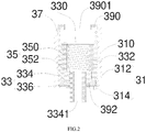
Fig. 2 is a schematic diagram of the structure of the atomizing core in the atomizer shown inFig. 1 ; -
Fig. 3 is a schematic structural diagram of the atomizer shown inFig. 1 when it is in an open position. - In order to facilitate understanding of the present invention, the present invention will be described more fully below with reference to the related drawings. The drawings show the preferred embodiments of the present invention. However, the present invention can be implemented in many different forms and is not limited to the embodiments described herein. Rather, these embodiments are provided to provide a thorough understanding of the disclosure of the present invention.
- It should be noted that when an element is referred to as being "fixed to" another element, it may be directly on the other element or there may be a centered element. When an element is considered to be "connected" to another element, it can be directly connected to the other element or intervening elements may also be present.
- Unless defined otherwise, all technical and scientific terms used herein have the same meaning as commonly understood by one of ordinary skill in the art to which this invention belongs. The terms used herein in the description of the present invention are only for the purpose of describing specific embodiments, and are not intended to limit the present invention. The term "and / or" as used herein includes any and all combinations of one or more of the associated listed items.
- The electronic cigarette includes a liquid storing member, an atomizer, a battery device (not shown), and a cigarette holder assembly. The liquid storing member is used to store e-liquid. The heating assembly located in the atomizer is electrically connected with the battery device, and is electrically driven by the battery device to heat the e-liquid absorbed form the liquid storing tube to form smoke. The smoke flows into the mouth of the smoker through the cigarette holder assembly.
- In order to atomize e-liquid under electric drive, the atomizer is usually provided with a liquid inlet in communicating with the liquid storage member. During use, the heating element absorbs the e-liquid stored in the liquid storage through the liquid inlet, and the smoke formed by heating the e-liquid under electric drive flows out to the cigarette holder assembly for the user to inhale. When not in use (for example, transportation or storage), because the liquid inlet is always in communication with the liquid storing member and the atomizer, the e-liquid stored in the liquid storing tube is easily adsorbed by the heating element, and a slow chemical reaction occurs in contact with heating element (metal), which is easy to cause the e-liquid to expire and deteriorate, affecting the taste and service life of the e-liquid.
- Please refer to
FIG. 1 , in one embodiment of the disclosure, the electronic cigarette includes anatomizer 100, a battery device (not shown), and a cigarette holder assembly. Theatomizer 100 is electrically connected to the battery device, and is electrically driven by the battery device to heat the absorbed e-liquid to form smoke, and the smoke flows into the mouth of the smoker through the cigarette holder assembly. The cigarette holder assembly is an independent component that is detachably connected to theatomizer 100 in some embodiments. In other embodiments, the cigarette holder assembly can also be integrated with theatomizer 100, which is not limited here. - The
atomizer 100 includes a housing 10 and an atomizingcore 30 assembled in the housing 10. The housing 10 is used to provide an installation basis and also used to store e-liquid, the atomizingcore 30 is used to absorb e-liquid and heat the adsorbed e-liquid under the drive of the battery device to form smoke. - The housing 10 is generally a hollow cylindrical structure, which includes a
bottom wall 110, aside wall 112 and abending wall 114. Anassembly hole 1101 is penetrated through thebottom wall 110 for installing the atomizingcore 30. Theside wall 112 extends in the same direction from the outer edge of thebottom wall 110 and encloses it to form a hollow space. Thebending wall 114 is connected to one end of theside wall 112 away from thebottom wall 110, thebending wall 114 is connected to an end of theside wall 112 away from thebottom wall 110, thebending wall 114 extends horizontally into the hollow space and then bends toward thebottom wall 110 to enclose asmoke outlet passage 1141. In this way, the hollow space is divided by thebending wall 114 to form asmoke outlet passage 1141 located in the inner ring and aliquid storage chamber 1143 surrounding the outer periphery of thesmoke outlet passage 1141. Theliquid storage chamber 1143 is used for storing e-liquid for atomization of the atomizingcore 30. Thesmoke outlet passage 1141 is in communication with theatomizer core 30 and the cigarette holder assembly, the smoke formed by theatomizer core 30 flows out to the cigarette holder assembly via thesmoke outlet passage 1141 under a suction action. - There is a certain distance between the end of the
bending wall 114 and thebottom wall 110 to provide an assembly space for the atomizingcore 30. That is, one end of the atomizingcore 30 extends through theassembly hole 1101 into the assembly space and is sealed between thebending wall 114. - Please refer to
FIG. 2 , the atomizingcore 30 is electrically connected to the battery device, and includes afixing base 31, amovable part 33 and aheating element 35. Thefixing seat 31 is fixedly assembled in the above-mentioned assembling space, and a side wall of thefixing seat 31 along the first direction is penetrated with aliquid inlet 310 in communication with theliquid storage chamber 1143. - An
atomization cavity 330 is defined in themovable part 33, and aliquid guiding port 332 in communication with theatomization cavity 330 is penetrated on the side wall along the first direction. Themovable part 33 is movably connected to the fixingseat 31 along the first direction, and reciprocates relative to the fixingseat 31 between the open positions of theliquid guiding port 332 and theliquid inlet 310 and the staggered closed positions of theliquid guiding port 332 and theliquid inlet 310. The first direction is the axial direction of the fixingseat 31. - The
heating assembly 35 is installed in theatomization cavity 330, and is used for heating the absorbed e-liquid under the electric drive of the battery device to form smoke when themovable member 33 is in the open position. Specifically, theheating element 35 includes aheating element 350 and aliquid guiding element 352 matched with theheating element 350. Theliquid guiding member 352 absorbs the e-liquid stored in theliquid storage chamber 1143 through theliquid inlet 310. Theheating element 350 is electrically connected to the battery device, and is used for heating the e-liquid absorbed by theliquid guiding element 352 under electric drive. In this specific embodiment, theheating element 350 is a heating column formed by spirally winding heating wires, the heating column is arranged vertically in theatomization cavity 330 along the axial direction, and the two ends of the axial direction are respectively connected with the positive and negative electrodes of the battery device, to form a heating electrically circuit with the battery device. - The
liquid guiding member 352 is a cylindrical liquid guiding member cotton sleeve outside of the heating column, and the liquid guiding member cotton covers theliquid guiding port 332 so as to absorb the e-liquid stored in theliquid storage chamber 1143 through theliquid guiding port 332. It can be understand, in some other embodiments, the structure of theheating element 350 and theliquid guiding element 352 can be determined as required, and only needs to realize the liquid guiding and heating atomization functions, which are not limited here. - The
atomizing core 30 includes a restoringmember 37 which is deformably disposed between themovable member 33 and the fixingseat 31 along the first direction, and is used to provide themovable member 33 with a restoring force that moves from the open position to the closed position. - The relative movement between the fixing
seat 31 and themovable part 33 realizes the opening and closing of theliquid guiding port 332 and theliquid inlet 310 of theatomizer 100, at the same time, it can also electrically drive theheating element 35 in theatomizing core 30, so that the structure of theatomizing core 30 is simple and compact. - The fixing
seat 31 includes aseat 312 and a limitingedge 314. Theseat 312 is a hollow tube with both ends passing through, the limitingedge 314 is formed by extending inwardly from the edge of one end of theseat 312. In this way, the fixingseat 31 is generally U-shaped in longitudinal section along the axial direction. - When the
movable element 33 is in the closed position, it is limited and supported on the limitingedge 314 along the first direction. Themovable element 33 includes amovable tube 334 having anatomization cavity 330 therein and apole 336. Themovable tube 334 is slidably connected to the fixingseat 31 along the first direction, one end of thepole 336 is fixedly connected to themovable tube 334, and the other end of thepole 336 protrudes outside of the fixingseat 31 in the closed position. - In one embodiment, the
pole 336 has anair inlet passage 3341 extending therethrough, theair inlet passage 3341 is in communication with the outside and theatomization cavity 332. The outside air is mixed with the smoke formed by heating in theatomization cavity 332 and flows out to the cigarette holder assembly through thesmoke outlet passage 1141 for the user to inhale. - The insulating assembly includes an insulating
cover 390 and an insulating member. The insulatingcover 390 is disposed on the end of theseat 31 away from the limitingedge 314, anairflow port 3901 for smoke to flow out is reserved on the insulatingcover 390. The resettingmember 37 abuts against the insulatingcover 390 and themovable tube 334, an insulating member is provided for insulation between themovable tube 334 and thepole 336. In one embodiment, the insulating member is an insulatingring 392. It can be understood that, in other embodiments, the insulatingcover 390 and the fixingseat 31 are integrally provided, the resettingmember 37 abuts between themovable tube 334 and the fixingseat 31. - The
movable tube 334 serves as the positive electrode or the negative electrode electrically connected to the battery device, or themovable tube 334 and the fixedseat 31 together serve as the positive electrode or the negative electrode electrically connected to the battery device, and thepole 336 serves as another electrode electrically connected to the battery device. In one of the embodiments, themovable tube 334 serves as a negative electrode electrically connected to the battery device, or themovable tube 334 and the fixingseat 31 together serve as a negative electrode electrically connected to the battery device, and thepole 336 forms a positive electrode electrically connected to the battery device. In this way, when theatomizing core 30 is mated with the battery device, the positive terminal of the battery device abuts against thepole 336, and the more protruding positive pole drives thepole 336 moving upward relative to the fixingbase 31 until thepole 336 is at least flush with the bottom of the fixingseat 31. At this time, the negative terminal of the battery device is in contact with the fixingbase 31, and themovable member 35 moves from the closed position to the open position relative to the fixingbase 31. - That is to say, the installation of the battery device and the atomizer of the disclosure provides the
movable part 35 in theatomizer core 30 with a driving force to move from the closed position to the open position relative to the fixingseat 31, that is, the positive terminal of the battery device is used to push thepole 336 ingeniously to realize the electrical connection while realizing the opening or closing of theliquid guiding port 332 and theliquid inlet 310. - Please refer to
FIG. 1 again, the housing 10 includes a base 13 provided at one end of theshell 11, and the outer surface of thebase 13 has a connecting thread to realize the detachable connection between theatomizer 100 and the battery device. That is to say, when theatomizer 100 is screwed to the battery device by screw fitting, themovable member 33 can conduct the air flow channel. - In the embodiment, the
base 13 is made of a metal conductive material and is electrically connected to the negative terminal of the battery device, so that themovable tube 334, the fixingbase 31 and themetal base 13 are all used as negative electrodes. At the same time, both the fixedseat 31 and themovable tube 334 are made of ceramics printed with a conductive layer, so that while the fixedseat 31 and themovable tube 334 are electrically connected and used as a negative electrode together, the lubricity of sliding between the two is increased by ceramic. It is understandable that in some other embodiments, thebase 13 and theshell 11 may be made of the same insulating material, and the two may be integrally formed, which is not limited herein. - In addition, the assembling method between the
atomizer 100 and the battery device can be determined according to needs, for example, by latching connection, when the two are assembled together, electrical connection and control of the air flow channel can be realized at the same time. In some other embodiments, the assembly between theatomizer 100 and the battery device may only be used to realize the electrical connection between the two, and the control of the airflow channel may be realized by other structures, which is not limited herein. In addition, theatomization cavity 310 and theliquid storage cavity 1143 in theatomizer 100 may be integrally arranged to avoid a gap formed between the liquid storage member and theatomization core 30 by threaded connection or docking, which may cause slow leakage of e-liquid. - Please refer to
FIG. 1 , when not in use, themovable member 33 located in theatomizing core 30 is in the closed position, theliquid guiding port 332 and theliquid inlet 310 are staggered. At this time, the e-liquid in theliquid storage chamber 1143 cannot enter theatomization cavity 330 through theliquid inlet 310 and theliquid guiding port 332 to be adsorbed by theliquid guiding member 352 to avoid long-term contact of the e-liquid with metal parts and affecting the taste. At the same time, the airflow entering theatomization cavity 330 from theair inlet channel 3341 cannot enter theliquid storage cavity 1143 through the staggeredliquid guide port 332 and theliquid inlet 310 to prevent air from entering theliquid storage cavity 1143 and affect the shelf life of the e-liquid. - Please refer to
FIG. 3 , when theatomizer 100 is connected to the battery device during use, the positive end of the battery device pushes up and squeezes thepole 336 until thepole 336 is flush with the bottom of the fixingseat 31. After themovable member 33 moves for a certain stroke under the upward squeezing force, theliquid guiding port 332 moves to communicate with theliquid inlet 310. At this time, the e-liquid stored in theliquid storage chamber 1143 can enter theatomization cavity 330 through theliquid inlet 310 and theliquid guiding port 332 to be adsorbed by theliquid guiding member 352. When electrically driven, thepole 336 is electrically connected to the positive terminal of the battery device, and the fixingbase 31, themovable tube 334 and themetal base 13 are all electrically connected to the negative terminal of the battery device to form an electric drive circuit. - The
heating element 350 is electrically driven to heat the smoke oil and form smoke. The external cold air enters theair inlet channel 3341 under the action of the suction force, and is mixed with the smoke in theatomization cavity 310, the mixed airflow flows through theairflow port 3901 into thesmoke outlet channel 1141 and enters the cigarette holder assembly for the user to inhale. - When it needs to be idle or not in use, the battery device is removed, and the
movable part 33 is reset under the action of the elastic force of thereset part 37, and is reset to the closed state again, so as to avoid long-term contact of the e-liquid in theliquid storage chamber 1143 with metal parts and affect the taste. It also avoids long-term contact of the e-liquid in theliquid storage chamber 1143 with the outside air and affects the shelf life. - In the disclosure, when the
atomizer 100 is assembled with the battery device, the positive terminal of the battery device squeezes the positive pole of theatomizer 100 upward, thereby realizing the conduction between the liquid guidingport 332 and theliquid inlet 310; When the battery device is not used for the first time or needs to be left unused after use, after the battery device is disassembled, themovable part 33 is reset under the action of the resettingpart 37 to stagger theliquid guiding port 332 and theliquid inlet 310 to seal the e-liquid and ensure the taste of smoke liquid and extend the shelf life. - The embodiments described above are merely preferred embodiments, but not intended to limit the application. Any modifications, alternatives or improvements made within the principle and spirit of the present application should be interpreted as falling within the protection scope of the present application. The claims are not limited to the features or acts described above. Rather, the proper scope of the disclosure is defined by the appended claims.
| Atomizer 100 | housing 10 |
| | |
| | |
| | |
| | Atomizing |
| | |
| | |
| | |
| Liquid guiding | |
| | |
| | Liquid guiding |
| Reseting | |
| | |
| | |
Claims (10)
- An atomizing core, comprising:a fixing base, a side wall of the fixing seat along a first direction is penetrated with a liquid inlet in communication with the liquid storage chamber;a movable part having an atomization cavity therein, the movable part is movably connected to the fixing seat along the first direction, a liquid guiding port in communication with the atomization cavity is penetrated on the side wall along the first direction; anda heating assembly installed in the atomization cavity;the movable part reciprocates in the first direction relative to the fixing seat between the open positions of the liquid guiding port and the liquid inlet and the staggered closed positions of the liquid guiding port and the liquid inlet, the movable part at least partially protrudes from the fixed seat in the closed position.
- The atomizing core according to claim 1, wherein the movable element comprises a movable tube defined with an atomization cavity therein and a pole, the movable tube is slidably connected to the fixing seat along the first direction, one end of the pole is fixedly connected to the movable tube, and the other end of the pole protrudes outside of the fixing seat in the closed position.
- The atomizing core according to claim 2, wherein the atomizing core comprises an insulating member, the insulating member is located between the movable tube and the pole.
- The atomizing core according to claim 3, wherein the insulating member is an insulating ring located between the movable tube and the pole, the movable tube serves as a negative electrode/or the movable tube and the fixed base serve as a negative electrode, the pole serves as a positive electrode, and the heating component is electrically connected to the negative electrode and the positive electrode.
- The atomizing core according to claim 4, wherein the fixed seat and the movable tube are made of ceramic material printed with printed with a conductive layer.
- The atomizing core according to claim 1, wherein the fixing seat comprises a seat and a limiting edge, the seat is a hollow tube with both ends extending therethrough along the first direction, the limiting edge is formed by extending inwardly from the edge of one end of the seat, when the movable tube is in the closed position, it is supported on the limiting edge along the first direction.
- The atomizing core according to claim 1, wherein the atomizing core comprises a restoring member which is deformably disposed between the movable member and the fixing seat along the first direction.
- An atomizer, comprising:
a housing and an atomizing core assembled in the housing, the liquid storage cavity is formed in the housing, and the atomizing core is the aforementioned atomization core. - An electronic cigarette comprising:
an atomizer and a battery device, the cigarette holder assembly, the installation of the battery device and the atomizer of the provides the movable part in the atomizer core with a driving force to move from the closed position to the open position relative to the fixing seat. - The atomizing core according to claim 9, wherein the housing comprises a base provided at one end of the shell, the base is made of a metal conductive material and is threadedly connected to the battery device.
Applications Claiming Priority (2)
| Application Number | Priority Date | Filing Date | Title |
|---|---|---|---|
| CN201821274581.8U CN208972674U (en) | 2018-08-08 | 2018-08-08 | Atomizers, Atomizers and Electronic Cigarettes |
| PCT/CN2019/099227 WO2020029911A1 (en) | 2018-08-08 | 2019-08-05 | Atomization core, atomizer and electronic cigarette |
Publications (2)
| Publication Number | Publication Date |
|---|---|
| EP3834640A1 true EP3834640A1 (en) | 2021-06-16 |
| EP3834640A4 EP3834640A4 (en) | 2022-05-04 |
Family
ID=66781146
Family Applications (1)
| Application Number | Title | Priority Date | Filing Date |
|---|---|---|---|
| EP19846505.6A Withdrawn EP3834640A4 (en) | 2018-08-08 | 2019-08-05 | Atomization core, atomizer and electronic cigarette |
Country Status (3)
| Country | Link |
|---|---|
| EP (1) | EP3834640A4 (en) |
| CN (1) | CN208972674U (en) |
| WO (1) | WO2020029911A1 (en) |
Cited By (3)
| Publication number | Priority date | Publication date | Assignee | Title |
|---|---|---|---|---|
| WO2024033485A1 (en) * | 2022-08-11 | 2024-02-15 | Philip Morris Products S.A. | Cartridge with compact internal activation unit |
| WO2024033489A1 (en) * | 2022-08-11 | 2024-02-15 | Philip Morris Products S.A. | Cartridge with sealed reservoir |
| WO2024033493A1 (en) * | 2022-08-11 | 2024-02-15 | Philip Morris Products S.A. | Cartridge with airflow management element and sealing element |
Families Citing this family (10)
| Publication number | Priority date | Publication date | Assignee | Title |
|---|---|---|---|---|
| CN208972674U (en) * | 2018-08-08 | 2019-06-14 | 常州市派腾电子技术服务有限公司 | Atomizers, Atomizers and Electronic Cigarettes |
| CN110250581B (en) * | 2019-06-26 | 2024-04-16 | 深圳市你我网络科技有限公司 | Atomizer and electronic cigarette |
| CN113068863A (en) * | 2020-01-04 | 2021-07-06 | 常州市派腾电子技术服务有限公司 | Atomizer and aerosol generating device |
| CN111685379A (en) * | 2020-07-15 | 2020-09-22 | 铂德(深圳)科技有限公司 | Atomizer for isolating and storing tobacco tar |
| CN111955797B (en) * | 2020-09-08 | 2024-05-28 | 绿烟实业(深圳)有限公司 | Electronic cigarette |
| CN112493558B (en) * | 2020-12-08 | 2024-07-02 | 深圳市华诚达精密工业有限公司 | Atomizing unit and atomizing device |
| CN113545527A (en) * | 2021-02-08 | 2021-10-26 | 深圳市吉迩科技有限公司 | Aerosol generating device |
| CN113907433A (en) * | 2021-11-03 | 2022-01-11 | 吉万(深圳)科技有限公司 | Atomizer and aerosol generating device |
| CN216701696U (en) * | 2021-12-29 | 2022-06-10 | 深圳市卓尔悦电子科技有限公司 | Liquid storage assembly, atomizer and aerosol generating device |
| CN115251461B (en) * | 2022-08-31 | 2026-01-20 | 深圳市吉迩技术有限公司 | Atomizer with switch and aerosol generating device |
Family Cites Families (6)
| Publication number | Priority date | Publication date | Assignee | Title |
|---|---|---|---|---|
| US10765144B2 (en) * | 2014-08-21 | 2020-09-08 | Rai Strategic Holdings, Inc. | Aerosol delivery device including a moveable cartridge and related assembly method |
| WO2016172898A1 (en) * | 2015-04-30 | 2016-11-03 | 惠州市吉瑞科技有限公司深圳分公司 | Atomizing component and electronic cigarette |
| CN205848694U (en) * | 2016-08-01 | 2017-01-04 | 深圳麦克韦尔股份有限公司 | Electronic cigarette and atomising device thereof |
| CN206443209U (en) * | 2016-11-02 | 2017-08-29 | 深圳市合元科技有限公司 | Atomizer and the electronic cigarette with the atomizer |
| CN108323814B (en) * | 2017-01-20 | 2023-12-01 | 常州市派腾电子技术服务有限公司 | Liquid storage components, atomizers and electronic cigarettes |
| CN208972674U (en) * | 2018-08-08 | 2019-06-14 | 常州市派腾电子技术服务有限公司 | Atomizers, Atomizers and Electronic Cigarettes |
-
2018
- 2018-08-08 CN CN201821274581.8U patent/CN208972674U/en active Active
-
2019
- 2019-08-05 EP EP19846505.6A patent/EP3834640A4/en not_active Withdrawn
- 2019-08-05 WO PCT/CN2019/099227 patent/WO2020029911A1/en not_active Ceased
Cited By (3)
| Publication number | Priority date | Publication date | Assignee | Title |
|---|---|---|---|---|
| WO2024033485A1 (en) * | 2022-08-11 | 2024-02-15 | Philip Morris Products S.A. | Cartridge with compact internal activation unit |
| WO2024033489A1 (en) * | 2022-08-11 | 2024-02-15 | Philip Morris Products S.A. | Cartridge with sealed reservoir |
| WO2024033493A1 (en) * | 2022-08-11 | 2024-02-15 | Philip Morris Products S.A. | Cartridge with airflow management element and sealing element |
Also Published As
| Publication number | Publication date |
|---|---|
| CN208972674U (en) | 2019-06-14 |
| WO2020029911A1 (en) | 2020-02-13 |
| EP3834640A4 (en) | 2022-05-04 |
Similar Documents
| Publication | Publication Date | Title |
|---|---|---|
| WO2020029911A1 (en) | Atomization core, atomizer and electronic cigarette | |
| US12053023B2 (en) | Cartridge and electronic cigarette | |
| EP3895562B1 (en) | Atomizing head, atomizer and electronic cigarette | |
| US11871794B2 (en) | Atomizer of electronic cigarette providing child protection function | |
| EP3510879A1 (en) | Cartridge and electronic cigarette having same | |
| CN204444245U (en) | Removable atomization unit and the atomizer and the electronic cigarette that comprise this atomization unit | |
| CN212164889U (en) | Atomizer and aerosol generating device | |
| CN209436272U (en) | Pods and Electronic Cigarettes | |
| US12029256B2 (en) | Power supply device, electronic cigarette, and assembly method | |
| US20240398023A1 (en) | Atomizer and atomization apparatus | |
| US12527354B2 (en) | Atomizer and aerosol generation device | |
| CN218354600U (en) | Electronic atomization device and atomizer thereof | |
| CN111990696A (en) | Aerosol generating device | |
| WO2025208723A1 (en) | Atomization device | |
| WO2023124322A1 (en) | Atomizer and aerosol generating device | |
| CN218898340U (en) | Atomizer and aerosol generating device | |
| CN216088846U (en) | Atomizer and atomization device | |
| CN216088847U (en) | Atomizer and atomization device | |
| CN110558615A (en) | Atomizing head, atomizing components, atomizer and electronic cigarette | |
| CN210017899U (en) | Atomizer and electronic cigarette | |
| CN116406828A (en) | Nebulizer and aerosol generating device | |
| CN220308443U (en) | Nebulizers and aerosol generating devices | |
| CN219982138U (en) | Aerosol generating device | |
| CN223365007U (en) | Atomizer body of rod structure and atomizer | |
| CN222510185U (en) | Atomizing device and atomizing equipment |
Legal Events
| Date | Code | Title | Description |
|---|---|---|---|
| STAA | Information on the status of an ep patent application or granted ep patent |
Free format text: STATUS: THE INTERNATIONAL PUBLICATION HAS BEEN MADE |
|
| PUAI | Public reference made under article 153(3) epc to a published international application that has entered the european phase |
Free format text: ORIGINAL CODE: 0009012 |
|
| STAA | Information on the status of an ep patent application or granted ep patent |
Free format text: STATUS: REQUEST FOR EXAMINATION WAS MADE |
|
| 17P | Request for examination filed |
Effective date: 20210223 |
|
| AK | Designated contracting states |
Kind code of ref document: A1 Designated state(s): AL AT BE BG CH CY CZ DE DK EE ES FI FR GB GR HR HU IE IS IT LI LT LU LV MC MK MT NL NO PL PT RO RS SE SI SK SM TR |
|
| DAV | Request for validation of the european patent (deleted) | ||
| DAX | Request for extension of the european patent (deleted) | ||
| REG | Reference to a national code |
Ref country code: DE Ref legal event code: R079 Free format text: PREVIOUS MAIN CLASS: A24F0047000000 Ipc: A24F0040480000 |
|
| A4 | Supplementary search report drawn up and despatched |
Effective date: 20220407 |
|
| RIC1 | Information provided on ipc code assigned before grant |
Ipc: A24F 40/10 20200101ALN20220401BHEP Ipc: A24F 40/44 20200101ALI20220401BHEP Ipc: A24F 40/42 20200101ALI20220401BHEP Ipc: A24F 40/48 20200101AFI20220401BHEP |
|
| STAA | Information on the status of an ep patent application or granted ep patent |
Free format text: STATUS: THE APPLICATION IS DEEMED TO BE WITHDRAWN |
|
| 18D | Application deemed to be withdrawn |
Effective date: 20221108 |