EP3834052B1 - Display device - Google Patents
Display device Download PDFInfo
- Publication number
- EP3834052B1 EP3834052B1 EP19863113.7A EP19863113A EP3834052B1 EP 3834052 B1 EP3834052 B1 EP 3834052B1 EP 19863113 A EP19863113 A EP 19863113A EP 3834052 B1 EP3834052 B1 EP 3834052B1
- Authority
- EP
- European Patent Office
- Prior art keywords
- stand
- display device
- locking device
- body portion
- disclosure
- Prior art date
- Legal status (The legal status is an assumption and is not a legal conclusion. Google has not performed a legal analysis and makes no representation as to the accuracy of the status listed.)
- Active
Links
Images






Classifications
-
- G—PHYSICS
- G06—COMPUTING OR CALCULATING; COUNTING
- G06F—ELECTRIC DIGITAL DATA PROCESSING
- G06F1/00—Details not covered by groups G06F3/00 - G06F13/00 and G06F21/00
- G06F1/16—Constructional details or arrangements
- G06F1/1601—Constructional details related to the housing of computer displays, e.g. of CRT monitors, of flat displays
-
- F—MECHANICAL ENGINEERING; LIGHTING; HEATING; WEAPONS; BLASTING
- F16—ENGINEERING ELEMENTS AND UNITS; GENERAL MEASURES FOR PRODUCING AND MAINTAINING EFFECTIVE FUNCTIONING OF MACHINES OR INSTALLATIONS; THERMAL INSULATION IN GENERAL
- F16M—FRAMES, CASINGS OR BEDS OF ENGINES, MACHINES OR APPARATUS, NOT SPECIFIC TO ENGINES, MACHINES OR APPARATUS PROVIDED FOR ELSEWHERE; STANDS; SUPPORTS
- F16M11/00—Stands or trestles as supports for apparatus or articles placed thereon ; Stands for scientific apparatus such as gravitational force meters
- F16M11/02—Heads
- F16M11/04—Means for attachment of apparatus; Means allowing adjustment of the apparatus relatively to the stand
- F16M11/043—Allowing translations
- F16M11/046—Allowing translations adapted to upward-downward translation movement
-
- F—MECHANICAL ENGINEERING; LIGHTING; HEATING; WEAPONS; BLASTING
- F16—ENGINEERING ELEMENTS AND UNITS; GENERAL MEASURES FOR PRODUCING AND MAINTAINING EFFECTIVE FUNCTIONING OF MACHINES OR INSTALLATIONS; THERMAL INSULATION IN GENERAL
- F16M—FRAMES, CASINGS OR BEDS OF ENGINES, MACHINES OR APPARATUS, NOT SPECIFIC TO ENGINES, MACHINES OR APPARATUS PROVIDED FOR ELSEWHERE; STANDS; SUPPORTS
- F16M11/00—Stands or trestles as supports for apparatus or articles placed thereon ; Stands for scientific apparatus such as gravitational force meters
- F16M11/02—Heads
- F16M11/18—Heads with mechanism for moving the apparatus relatively to the stand
-
- F—MECHANICAL ENGINEERING; LIGHTING; HEATING; WEAPONS; BLASTING
- F16—ENGINEERING ELEMENTS AND UNITS; GENERAL MEASURES FOR PRODUCING AND MAINTAINING EFFECTIVE FUNCTIONING OF MACHINES OR INSTALLATIONS; THERMAL INSULATION IN GENERAL
- F16M—FRAMES, CASINGS OR BEDS OF ENGINES, MACHINES OR APPARATUS, NOT SPECIFIC TO ENGINES, MACHINES OR APPARATUS PROVIDED FOR ELSEWHERE; STANDS; SUPPORTS
- F16M11/00—Stands or trestles as supports for apparatus or articles placed thereon ; Stands for scientific apparatus such as gravitational force meters
- F16M11/20—Undercarriages with or without wheels
- F16M11/24—Undercarriages with or without wheels changeable in height or length of legs, also for transport only, e.g. by means of tubes screwed into each other
-
- F—MECHANICAL ENGINEERING; LIGHTING; HEATING; WEAPONS; BLASTING
- F16—ENGINEERING ELEMENTS AND UNITS; GENERAL MEASURES FOR PRODUCING AND MAINTAINING EFFECTIVE FUNCTIONING OF MACHINES OR INSTALLATIONS; THERMAL INSULATION IN GENERAL
- F16M—FRAMES, CASINGS OR BEDS OF ENGINES, MACHINES OR APPARATUS, NOT SPECIFIC TO ENGINES, MACHINES OR APPARATUS PROVIDED FOR ELSEWHERE; STANDS; SUPPORTS
- F16M11/00—Stands or trestles as supports for apparatus or articles placed thereon ; Stands for scientific apparatus such as gravitational force meters
- F16M11/20—Undercarriages with or without wheels
- F16M11/24—Undercarriages with or without wheels changeable in height or length of legs, also for transport only, e.g. by means of tubes screwed into each other
- F16M11/242—Undercarriages with or without wheels changeable in height or length of legs, also for transport only, e.g. by means of tubes screwed into each other by spreading of the legs
-
- G—PHYSICS
- G02—OPTICS
- G02F—OPTICAL DEVICES OR ARRANGEMENTS FOR THE CONTROL OF LIGHT BY MODIFICATION OF THE OPTICAL PROPERTIES OF THE MEDIA OF THE ELEMENTS INVOLVED THEREIN; NON-LINEAR OPTICS; FREQUENCY-CHANGING OF LIGHT; OPTICAL LOGIC ELEMENTS; OPTICAL ANALOGUE/DIGITAL CONVERTERS
- G02F1/00—Devices or arrangements for the control of the intensity, colour, phase, polarisation or direction of light arriving from an independent light source, e.g. switching, gating or modulating; Non-linear optics
- G02F1/01—Devices or arrangements for the control of the intensity, colour, phase, polarisation or direction of light arriving from an independent light source, e.g. switching, gating or modulating; Non-linear optics for the control of the intensity, phase, polarisation or colour
- G02F1/13—Devices or arrangements for the control of the intensity, colour, phase, polarisation or direction of light arriving from an independent light source, e.g. switching, gating or modulating; Non-linear optics for the control of the intensity, phase, polarisation or colour based on liquid crystals, e.g. single liquid crystal display cells
- G02F1/133—Constructional arrangements; Operation of liquid crystal cells; Circuit arrangements
- G02F1/1333—Constructional arrangements; Manufacturing methods
- G02F1/133308—Support structures for LCD panels, e.g. frames or bezels
-
- G—PHYSICS
- G06—COMPUTING OR CALCULATING; COUNTING
- G06F—ELECTRIC DIGITAL DATA PROCESSING
- G06F1/00—Details not covered by groups G06F3/00 - G06F13/00 and G06F21/00
- G06F1/16—Constructional details or arrangements
- G06F1/1601—Constructional details related to the housing of computer displays, e.g. of CRT monitors, of flat displays
- G06F1/1607—Arrangements to support accessories mechanically attached to the display housing
-
- H—ELECTRICITY
- H05—ELECTRIC TECHNIQUES NOT OTHERWISE PROVIDED FOR
- H05K—PRINTED CIRCUITS; CASINGS OR CONSTRUCTIONAL DETAILS OF ELECTRIC APPARATUS; MANUFACTURE OF ASSEMBLAGES OF ELECTRICAL COMPONENTS
- H05K5/00—Casings, cabinets or drawers for electric apparatus
- H05K5/0017—Casings, cabinets or drawers for electric apparatus with operator interface units
-
- H—ELECTRICITY
- H05—ELECTRIC TECHNIQUES NOT OTHERWISE PROVIDED FOR
- H05K—PRINTED CIRCUITS; CASINGS OR CONSTRUCTIONAL DETAILS OF ELECTRIC APPARATUS; MANUFACTURE OF ASSEMBLAGES OF ELECTRICAL COMPONENTS
- H05K5/00—Casings, cabinets or drawers for electric apparatus
- H05K5/02—Details
- H05K5/0217—Mechanical details of casings
- H05K5/0234—Feet; Stands; Pedestals, e.g. wheels for moving casing on floor
-
- F—MECHANICAL ENGINEERING; LIGHTING; HEATING; WEAPONS; BLASTING
- F16—ENGINEERING ELEMENTS AND UNITS; GENERAL MEASURES FOR PRODUCING AND MAINTAINING EFFECTIVE FUNCTIONING OF MACHINES OR INSTALLATIONS; THERMAL INSULATION IN GENERAL
- F16M—FRAMES, CASINGS OR BEDS OF ENGINES, MACHINES OR APPARATUS, NOT SPECIFIC TO ENGINES, MACHINES OR APPARATUS PROVIDED FOR ELSEWHERE; STANDS; SUPPORTS
- F16M2200/00—Details of stands or supports
- F16M2200/08—Foot or support base
-
- H—ELECTRICITY
- H04—ELECTRIC COMMUNICATION TECHNIQUE
- H04N—PICTORIAL COMMUNICATION, e.g. TELEVISION
- H04N5/00—Details of television systems
- H04N5/64—Constructional details of receivers, e.g. cabinets or dust covers
- H04N5/655—Construction or mounting of chassis, e.g. for varying the elevation of the tube
Definitions
- the present disclosure relates to a display device, and more particularly, to a display device including a stand unit.
- display devices are apparatuses for displaying a screen, such as monitors, televisions, etc.
- the display device may include an actively light-emitting display panel such as Organic Light Emitting Diodes (OLEDs) and a passively light-emitting display panel such as Liquid Crystal Displays (LCDs).
- OLEDs Organic Light Emitting Diodes
- LCDs Liquid Crystal Displays
- Modern display devices may be used by being installed on the wall or by being held up by a stand on the floor depending on the user's preference.
- Examples of display devices that include stands which can be folded away when not in use can be found within the following disclosures: CN 201409 187 Y , EP 1803 985 A2 , WO 2008/046325 A1 , TW 201146 005 A , US 2013/107430 A1 and US 7 328 880 B2 .
- the present disclosure provides a display device including a stand unit having an enhanced structure to selectively pull in a stand member that supports the display device on the floor.
- the present disclosure also provides a display device including a stand member that is not exposed when the display device is installed on the wall.
- the present disclosure also provides a display device having a stand member easily pulled out to support the display device on the floor.
- a display device may include a stand unit that pulls a stand member into the display device when the display device is installed on the wall and pulls out the stand member to support the display device when the display device is placed on the floor, thereby eliminating the need for keeping the stand member separately, and thus preventing losing the stand member.
- the stand member may be pulled in the display device not be exposed when the display device is installed on the wall, thereby improving the beauty of the display device.
- the stand member may be easily pulled from inside the display device, thereby increasing user convenience.
- first and second may be used to explain various components, but the components are not limited by the terms. The terms are only for the purpose of distinguishing a component from another. Thus, a first element, component, region, layer or chamber discussed below could be termed a second element, component, region, layer or section without departing from the teachings of the present disclosure. Descriptions shall be understood as to include any and all combinations of one or more of the associated listed items when the items are described by using the conjunctive term " ⁇ and/or ⁇ ,” or the like.
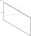
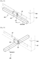
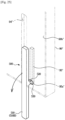
- FIG. 1 is a perspective view of a display device, according to a first embodiment of the disclosure
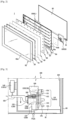
- FIG. 2 is an exploded perspective view of the display device, according to the first embodiment of the disclosure.
- the movable housing 131 and 132 may be movable against the fixed housing 133, i.e., movable while coupled with the fixed housing 133.
- the stand 110 may be coupled with the movable housing 131 and 132, it may be movably coupled with the fixed housing 133 through the movable housing 131. Hence, the housing 130 may prevent deviation of the stand 110 from the case 120 while the stand 110 is moving.
- the stand 110 may be moved down until the contact 132a contacts the stopper 170, and in the state of contact between the stopper 170 and the contact 132a, the stand 110 is restricted by the stopper 170 from moving down.
- the gas cylinder 140 may transmit force created from the contraction or the expansion to the stand 110 for the supporting portion 112 to be rotated in a state of being pulled from the display device 1. This will be described in more detail later.
- the stand 110 may be placed in a pull-in position 110A.
- the movable housing 131 and 132 and the transmitter 150 engaged with the stand 110 may be in positions corresponding to the pull-in position 110A of the stand 110.
- the gas cylinder 140 is connected to the transmitter 150, and the gas cylinder 140 may go into a contraction state 140A as the transmitter 150 is in a position corresponding to the highest position of the stand 110.
- the stand 110 When the stand 110 is placed in the pull-in position 110A, it lies inside the case 120 or display device 1 and is not exposed.
- a through hole 91 is arranged on the rear side 90a of the rear cover 90 for the stand 110 to pass through in the vertical direction.
- the through hole 91 may be formed to be equal to or greater than the cross-sectional area of the supporting portion 112 of the stand 110 for the supporting portion 112 to pass through the through hole 91.
- a shape of the through hole 91 may match the shape of the supporting portion 112.
- the user may push the stand 110 upward to pull the stand 110 out of the display device 1.
- the locked portion 114 may be unlocked, and the stand 110 may be unlocked accordingly.
- the stand 110 and the movable housing 131 and 132 may move down by their self-weights, and accordingly, the supporting portion 112 may pass through the opening 121 of the case 120 and the through hole 91 of the rear cover 90 and may be pulled down from the display device 1.
- the stand 110 may be placed in a middle position 110B by moving down from the pull-in position 110A.
- the movable housing 131 and 132, and the transmitter 150 and gear portion 180 coupled with the combining housing 132 may also be engaged and moved down with the stand 110.
- the piston of the gas cylinder 140 engaged with the transmitter 150 is moved down, and hence, the gas cylinder 140 may go into the expansion state B.
- the supporting portion 112 may include a first supporter 112a and a second supporter 112b.
- the stand 110 may include a rotation shaft 113 provided for the first and second supporters 112a and 112b to be rotated around.
- the rotation shaft 113 may extend in an extending direction of the stand 110, and may be arranged in the extending direction of the stand 110.
- the first and second supporters 112a and 112b may be each provided to be rotational around the rotation shaft 113. Since the rotation shaft 113 vertically extends in the extending direction of the stand 110, as described above, the first and second supporters 112a and 112b may be rotated horizontally.
- the first and second supporters 112a and 112b may be put into the through hole 91 and the opening 121 while contacting each other.
- the through hole 91 or the opening 121 is formed to have a shape matching the shape of the supporter 112 and have a cross section in a similar size to the supporter 112, so that the through hole 91 or the opening 121 may keep the first and second supporters 112a and 112b in the state of contacting each other.
- horizontal rotation of the first or second supporter 112a or 112b around the rotation shaft 113 may be restricted by the through hole 91 or the opening 121.
- the supporting portion 112 is pulled from the through hole 91 and the opening 121, and the first and second supporters 112a and 112b may be rotated without restriction.
- the first and second supporters 112a and 112b may go into a rotational state.
- the gas cylinder 140 Since the gas cylinder 140 is in the expansion state B, the gas cylinder 140 creates force by contraction and expansion, and the force may drive the gear portion 180 via the transmitter 150.
- the stand gear 115 in gear with the gear portion 185 may be rotated, and the body portion 111 may be rotated by being engaged with the rotation with the stand gear 115.
- the supporting portion 112 coupled with the body portion 111 may be engaged with rotation of the body portion 111 for the first and second supporters 112a and 112b to be rotated in opposite directions.
- the gear portion 180 may control rotation speed of the first and second supporters 112a and 112b. Specifically, a plurality of gears are arranged in the gear portion 180, and the rotation speed of the first and second supporters 112a and 112b may be controlled appropriately based on the size or arrangement of each of the gears.
- the gear portion 180 may help the supporting portion 112 rotate stably, and, as described above, control the rotation speed, thereby increasing reliability and beauty of the supporting portion 112 when the supporting portion 112 is rotated.
- the stand 110 may include an elastic member provided to rotate the first and second supporters 112a and 112b.
- the elastic member may be provided to rotate the first and second supporters 112a and 112b in opposite directions when the stand 110 is placed in the middle position 110B by pushing the first and second supporters 112a and 112b in the opposite directions.
- the elastic member may be formed with a member such as a torsion spring.
- the elastic member may push the first and second supporters 112a and 112b to rotate them.
- the elastic member may be arranged to apply torque onto the first and second supporters 112a and 112b around the rotation shaft 113 as a rotation axis.
- the stand unit 100 may not include some components such as the aforementioned gas cylinder 140 and transmitter 150.
- the stand unit 100 may rotate the supporting portion 112 simply with the elastic member.
- the stand unit 100 is not limited to what is described in the first embodiment, and may rotate the supporting portion 112 just with the force of the gas cylinder 140.
- rotation force is applied to the supporting portion 112 and the first and second supporters 112a and 112b are rotated in opposite directions until placed in front and back of the display device 1, respectively.
- the position of the stand 110 may be changed by rotation of the first and second supporters 112a and 112b from the middle position 110B to a supporting position 110C.
- the first and second supporters 112a and 112b may form a shape spreading around the rotation shaft 113.
- the first supporter 112a may be placed in front of the display device 1, and the second supporter 112b may be placed in the back of the display device 1.
- the supporting portion 112 may support the display device 1 from front and back, thereby placing the display device 1 stably on the floor with the stand 110 when the display device 1 is installed in the stand-type.
- the display device 1 may be supported on the floor in the stand-type with the stand 110 pulled out and placed in the supporting position 110C, and the display device 1 may be supported on the wall in the mount-type by pulling the stand 110 into the display device 1 in the pull-in position 110A.
- the user may pull the stand 110 back into the display device 1 from the supporting position 110C by reversing the aforementioned process.
- the user may push the unfolded first and second supporters 112a and 112b in the supporting position 110C to be folded together, and push the supporting portion 112 upward to move the stand 110 upward, thereby forcing the locked portion 114 of the stand 110 to be inserted back into the locking device 160 and constrained by the locking device 160.
- the stand 110 When the stand 110 is locked in the locking device 160, the stand 110 is placed back in the pull-in position 110A and not exposed.
- the stand unit 100 may selectively pull the stand 110 into or out of the display device 1. Accordingly, even in a situation where the display device 1 is to be installed in the mount-type that does not require the stand 110, the stand 110 may be pulled into the display device 1, thereby eliminating the need to keep the stand 110 separately and concerns about losing the stand 110.
- the user may pull the stand 110 out of the display device 1 by simply pushing the inner side of the through hole 91 formed at the bottom of the display device 1.
- the stand unit 200 may also include a locking device 260 to fix the stand 210 by locking the stand 210 to remain in a state of being received in the case 220.
- the housing 230 may include a movable housing 231 through which the stand 210 passes and which is engaged with the stand 210 to be movable in the vertical direction, and a fixed housing 232 fixed to the case 220.
- the movable housing 231 may be movable against the fixed housing 232, i.e., movable in a state of being coupled with the fixed housing 232.
- the stand unit 200 may further include a guide 240 for guiding vertical movement of the stand 210 and the movable housing 231.
- the guide 240 may include a rack 241 extending vertically, and a pinion 242 coupled in gear with the rack 241 and arranged in the movable housing 231.
- the stand 210 may include a body portion 211, a locked portion 214 arranged on the top of the body portion 211 and inserted to and constrained by a locking device 260, and the supporting portion 212 provided to be pulled out of the display device 1 when the stand 210 is unlocked and thus to support the display device 1 from the floor.
- the stand 210 may be placed in a pull-in position 210A.
- the movable housing 231 engaged with the stand 210 may be in a position corresponding to the pull-in position 210A of the stand 110.
- the stand 210 When the stand 210 is placed in the pull-in position 210A, it lies inside the case 220 or display device 1 and is not exposed.
- the stand 210 When the stand 210 is placed in the pull-in position 210A, it is not pulled out of the through hole 91 and thus, not exposed, but it is possible for the user to push the stand 210 upward through the through hole 91 from the outside.
- the user may push the stand 210 upward to pull the stand 210 out of the display device 1.
- the locked portion 214 inserted to the locking device 260 may be moved up to push the locking device 260 from inside the locking device 260.
- the locked portion 214 may be unlocked, and the stand 210 may be unlocked accordingly.
- the stand 210 may move down by its self-weight.
- the stand 210 and the movable housing 231 may move down by their self-weights, and accordingly, the supporting portion 212 may pass through an opening 221 of the case 220 and the through hole 91 of the rear cover 90 and may be pulled down from the display device 1.
- the stand 210 may be placed in a middle position 210B by moving down from the pull-in position 210A.
- the supporting portion 212 may include a first supporter 212a and a second supporter 212b.
- the first supporter 212a may be placed in front of the display device 1, and the second supporter 212b may be placed in the back of the display device 1.
- the stand 210 may include a rotation shaft 213 provided for the first and second supporters 212a and 212b to be rotated around.
- the rotation shaft 213 may extend in a direction parallel to the length of the display device 1. Specifically, the rotation shaft 213 may extend in the horizontal direction of the display device 1 and may be arranged in the horizontal direction of the display 1.
- the first and second supporters 212a and 212b may be each provided to be rotational around the rotation shaft 213. Since the rotation shaft 213 extends in the horizontal direction of the display device 1, as described above, the first and second supporters 212a and 212b may be turned to the front and back with respect to the horizontal direction of the display device 1.
- first supporter 212a may be turned to the front of the display device 1
- second supporter 212b may be turned to the back of the display device 1.
- the first and second supporters 212a and 212b may be put into the through hole 91 and the opening 121 while contacting each other.
- the through hole 91 or the opening 121 may keep the first and second supporters 212a and 212b in the state of contacting each other.
- the supporting portion 212 is pulled from the through hole 91 and the opening 121, and the first and second supporters 212a and 212b may be rotated without restriction.
- the first and second supporters 212a and 212b may go into a rotational state.
- the stand 210 may include an elastic member provided to rotate the first and second supporters 212a and 212b.
- the elastic member may be provided to rotate the first and second supporters 212a and 212b in opposite directions when the stand 210 is placed in the middle position 210B by pushing the first and second supporters 212a and 212b in the opposite directions.
- the elastic member may be formed with a member such as a torsion spring.
- the elastic member may push the first and second supporters 212a and 212b to be rotated.
- the elastic member may be arranged to be able to apply torque onto the first and second supporters 212a and 212b around the rotation shaft 213 as a rotation axis.
- the stand 210 may include a restricting member 215 to constrain the first and second supporters 212a and 212b.
- the restricting member 215 may restrict the first and second supporters 212a and 212b from being rotated by the elastic member at the pull-in position 210A or the middle position 210B.
- the restricting member 215 may constrain the first and second supporters 212a and 212b for the stand 210 to be moved stably.
- the restricting member 215 is provided to be hooked with the first and second supporters 212a and 212b inside the body portion 211. It is not, however, limited thereto, but the restricting member 215 may be provided in various forms to constrain or release the first and second supporters 212a and 212b.
- the guide 240 may guide the moving direction of the stand 210 through the rack 241 and the pinion 242 and simultaneously, control the moving speed of the stand 210.
- the speed at which the stand 210 moves up or down may be controlled by adjusting the size or arrangement of the rack 241 and pinion 242.
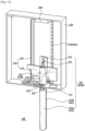
- rotation force is applied to the supporting portion 212 and the first and second supporters 212a and 212b are rotated in opposite directions until placed in front and back of the display device 1, respectively.
- the restricting member 215 may vertically slide in the body portion 211.
- the restricting member 215 may be moved down and constraints of the restricting member 215 on the first and second supporters 212a and 212b may be released.
- the first and second supporters 212a and 212b may form a shape spreading around the rotation shaft 213.
- the first supporter 212a may be placed in front of the display device 1, and the second supporter 212b may be placed in the back of the display device 1.
- FIG. 15 shows a stand unit of a display device with a stand member pulled in, according to a third embodiment of the disclosure
- FIG. 16 is a bottom perspective view of the display device with the stand member pulled in, according to the third embodiment of the disclosure
- FIG. 17 shows the stand unit of the display device with the stand member partially pulled out
- FIG. 18 is a bottom perspective view of the display device with the stand member partially pulled out, according to the third embodiment of the disclosure
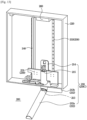
- FIG. 19 shows the stand unit of the display device with the stand member fully pulled out, according to the third embodiment of the disclosure
- FIG. 20 is a bottom perspective view of the display device with the stand member fully pulled out, according to the third embodiment of the disclosure.
- the stand unit 300 may include a stand 310 provided to be movable in the vertical direction, a case 320, and a housing 330 fixed to the case 310 to allow the stand 310 to be pulled in or out of the case 320.
- the stand unit 300 may also include a locking device 360 to fix the stand 310 by locking the stand 310 to remain in a state of being received in the case 320.
- the locking device 360 may be arranged on the top of the stand 310. At least a portion of the stand 310 may be put into and constrained by the locking device 360, and accordingly, the stand 310 may be locked in the locking device 360.
- the stand 310 When the stand 310 is released from the locked state, the stand 310 may be moved down by its self-weight. Accordingly, the stand 310 may be pulled out of the case 320.
- the stand 310 When the stand 310, which has been pulled out, is pushed up, the stand 310 is moved up again by the external force, and at least a portion of the stand 310 in turn pushes the locking device 360 and accordingly, is constrained back in the locking device 360, ending up with the stand 310 being pulled back into the case 320.
- the housing 330 may include a first housing 330a coupled with the case 320 and a second housing 330b coupled with the first housing 330a. Certain space may be formed between the first and second housings 330a and 330b for the stand 310 to be inserted thereto.
- the stand 310 is inserted to the certain space, and the first and second housings 320a and 320b may be combined.
- the stand 310 may be moved vertically in the certain space.
- the stand 310 may include a body portion 311 inserted to the housing 330, a locked portion 314 arranged on the top of the body portion 311 and inserted to and constrained by a locking device 360, and the supporting portion 312 provided to be pulled out of the display device 1 when the stand 310 is unlocked and thus support the display device 1 from the floor.
- the second housing 330b may include a guide projection 331 for guiding movement of the body portion 311. It is not, however, limited thereto, and the guide projection 331 may be arranged in the first housing 330a in another embodiment.
- the body portion 331 may include a rail 316 to which the guide projection 331 is inserted.
- the body portion 331 may be vertically moved while the guide projection 331 is inserted to the rail 316.
- the body portion 331 may be moved along the direction in which the rail 316 extends.
- At least a portion of the rail 316 may extend straight vertically, and some other portion of the rail 316 may be curved in the vertical direction.
- the body portion 331 may be moved vertically when the guide projection 331 is in the straight portion of the rail 316, and may be rotated along the curve of the rail 316 when the guide projection 331 is in the curved portion. This will be described in more detail later.
- the stand 310 may be placed in a pull-in position 310A.
- the supporting portion 312 may be located in a receiving groove 322 (see FIG. 19 ) formed on the bottom side of the case 320.
- the supporting portion 312 may be provided to be perpendicular to the body portion 311, and when the stand 310 is placed in the pull-in position 310A, may lie along the length of the display device 1.
- the supporting portion 312 may lie in the horizontal direction of the display device 1.
- the receiving groove 322 may also be formed to extend along the horizontal direction of the display device 1.
- the stand 310 When the stand 310 is placed in the pull-in position 310A, it lies inside the case 320 or display device 1 and is not exposed.
- the stand 310 When the stand 310 is placed in the pull-in position 310A, it is not pulled out of the through hole 91 and thus, not exposed, but it is possible for the user to push the stand 310 upward through the through hole 91 from the outside.
- the user may push the stand 310 upward to pull the stand 310 out of the display device 1.
- the locked portion 314 inserted to the locking device 360 may be moved up to push the locking device 360 from inside the locking device 360.
- the locked portion 314 may be unlocked, and the stand 310 may be unlocked accordingly.
- the stand 310 may move down by its self-weight.
- the stand 310 may move down by the self-weight, and accordingly, the supporting portion 312 may be pulled out of the receiving groove 322 of the case 320 and may pass through the through hole 91 of the rear cover 90, and the body portion 311 may be pulled down through the opening323 of the case 320.
- the stand 310 may be placed in a middle position 310B by moving down from the pull-in position 310A.
- the guide projection 331 may be placed in a first area 316a of the rail 316.
- the first area 316a is an area in which the rail 316 extends straight in the vertical direction.
- the guide projection 331 may guide the stand 310 for the body portion 311 to be moved in the vertical direction.
- the supporting portion 312 may then be moved down by keeping the direction in which the supporting portion 312 lies that corresponds to the horizontal direction of the display device 1.
- the body portion 311 may be moved down by being rotated in one direction along the curve of the second area 316b.
- the supporting portion 312 may be moved down by being engaged with the body portion 311 and rotated in one direction.
- the stand unit 300 may further include a gear portion coupled to the body portion 311.
- the gear portion may include a plurality of gears, in which case at least one gear may be coupled to the body portion 311 and at least another gear may be coupled to the housing 330.
- Moving speed of the stand 310 may be controlled by the gear portion, enabling the stand 310 to be stably moved, thereby increasing reliability and beauty of the stand 310.
- the guide projection 331 when the guide projection 331 reaches an end 316c of the second area 316b of the rail 316, the guide projection 331 may be stuck in the rail 316 and the body portion 311 may not move down any longer and keep the fallen state.
- the stand 310 may then be in a supporting position 310C at which to support the display device 1.
- the supporting portion 312 may be engaged with the body portion 311 and rotated along the curve of the rail 316, e.g., about 90 degrees in one direction.
- the length and curvature of the curve of the second area 316b may be adjusted such that the body portion 311 may be rotated about 90 degrees until the guide projection 331 reaches the end 316c.
- the supporting portion 312 may lie in a direction from front to back of the display device 1. Hence, the supporting portion 312 may stably support the display device 1.
- a stopper may be included to keep the state in which the guide projection 331 and the end 316c come into contact with each other.
- the stopper may be a section of the rail 316 extending from the end 316c to the opposite for restricting the guide projection 331 from moving, and may be provided separately to press the body portion 311 to restrict movement of the body portion 311.
- the stand 310 may be rotated to change the direction in which the supporting portion 312 lies while moving from the middle position 310B to the supporting position 310C.
- the stand unit 300 may place the stand 310 to support the display device 1.
- FIG. 21 is a rear perspective view of a display device with a stand member pulled in, according to a fourth embodiment of the disclosure
- FIG. 22 is a rear perspective view of the display device with the stand member pulled in, according to the fourth embodiment of the disclosure
- FIG. 23 is a rear perspective view of the display device with the stand member fully pulled out, according to the fourth embodiment of the disclosure.
- the display device 1 may include a stand unit 400 that may be pulled in or out of a rear side 90b' of a rear cover 90'.
- the stand unit 400 may include a stand 410 provided to support the display device 1 when the stand unit 400 is pulled out of the rear cover 90', a hinge part 420 provided for the stand 410 to be turned to a first direction or a second direction which is perpendicular to the first direction, and a rotation shaft 430 provided for the stand 410 to be rotated in the first or second direction.
- the rotation shaft 430 may include a first rotation shaft 431 provided for the stand 410 to be turned in the first direction, and a second rotation shaft 432 provided for the stand 410 to be turned in the second direction.
- the first rotation shaft 431 may be provided to bore through the hinge part 420 and have both ends placed inside the rear cover 90'.
- the second rotation shaft 432 may be provided to bore through the stand 410 and the hinge part 420 for the stand 410 to be rotated against the hinge part 420.
- the hinge part 420 may be rotated by the first rotation shaft 431 against the rear cover 90'. Specifically, the hinge part 420 may be coupled with the rear cover 90' to be turned to the front and back of the display device 1.
- the stand 410 may be coupled with the hinge part 420 to be rotated by the second rotation shaft 432 against the hinge part 420.
- the hinge part 420 may be rotationally coupled with the rear cover 90' and the stand 410 may be rotationally coupled with the hinge part 420.
- the stand 410 When the stand 410 is placed in the pull-in position 410A, it lies inside the rear cover 90' or display device 1 and is not exposed.
- the stand 410 may be pulled into a receiving groove 92' formed on a rear side 90b' of the rear cover 90'.
- the stand 410 is not pulled out of the receiving groove 92' and thus, not exposed, but it is possible for the user to pull out the stand 410 through the receiving groove 92'.
- the user may pull out the stand 410 from the receiving groove 92'.
- the stand 410 When the stand 410 is pulled out, it may be turned down around the first rotation shaft 431 by its self-weight.
- the stand 410 may be turned down by its self-weight, and thus pulled down from the display device 1.
- the stand 410 may be placed in a middle position 410B by moving down from the pull-in position 410A.
- the user may turn the stand 410 around the second rotation shaft 432, in which case since the second rotation shaft 432 extends vertically, the stand 410 may be turned to the front and back of the display device 1.
- the stand unit 400 may further include a gear portion arranged between the stand 410 and the hinge part 420.
- the gear portion may include a plurality of gears, in which case at least one gear may be coupled to the stand 410 and at least another gear may be coupled to the hinge part 420.
- Moving speed of the stand 410 may be controlled by the gear portion, enabling the stand 410 to be stably turned, thereby increasing reliability and beauty of the stand 410.
- the stand 410 is turned to the front and back of the display device 1 to be in a supporting position 410C at which to support the display device 1.
- the stand 410 may be rotated about 90 degrees against the hinge part 420.
- the hinge part 420 may include a stopper (not shown) for the stand 410 to be rotated about 90 degrees against the hinge part 420.
- the stopper may restrict rotation of the stand 410 such that the stand 410 is not rotated more than about 90 degrees against the hinge part 420.
- the stand unit 400 may further include a stand check member (not shown) to prevent the stand 410 from being turned in the opposite direction after the stand 410 is turned about 90 degrees.
- the stand check member may check rotation of the stand 410 to prevent the stand 410 from being turned to any direction after the stand 410 is rotated 90 degrees against the hinge part 420, thereby enabling the stand 410 to stably support the display device 1.
- FIG. 24 is a rear perspective view of the display device with the stand member pulled in, according to the fifth embodiment of the disclosure
- FIG. 25 is a rear perspective view of the display device with the stand member pulled in, according to the fifth embodiment of the disclosure
- FIG. 26 is a rear perspective view of the display device with the stand member fully pulled out, according to the fifth embodiment of the disclosure.
- the display device 1 may include a stand unit 500 that may be pulled in or out of a rear side 90b" of a rear cover 90".
- the stand unit 500 may include a stand 510 provided to support the display device 1 when the stand unit 500 is pulled out of the rear cover 90", a hinge part 520 provided for the stand 510 to be turned, and a rotation shaft 530 provided for the stand 510 to be turned.
- the stand 510 may be in a pull-in position 510A, when the display device 1 is in a packaged state or installed on the wall in the mount-type.
- the stand 510 When the stand 510 is placed in the pull-in position 510A, it lies inside the rear cover 90" or display device 1 and is not exposed.
- the stand 510 may be pulled into a first receiving groove 94" formed on the rear side 90b" of the rear cover 90".
- the hinge part 520 and the rotation shaft 530 may be pulled in a second receiving groove 95" formed inside the rear cover 90".
- the stand 510 is not pulled out of the first receiving groove 94" and thus, not exposed, but it is possible for the user to pull out the stand 510 through the first receiving groove 94".
- the user may push the stand 510 downward through the first receiving groove 94".
- the stand 510 and the hinge part 520 may be integrally formed. Furthermore, the rotation shaft 530 may penetrate the hinge part 520. Accordingly, the hinge part 520 and the rotation shaft 530 may be moved down by being engaged with the stand 510.
- the hinge part 520 and the rotation shaft 530 may be moved down along the second receiving groove 95".
- the first receiving groove 94" may be formed on the rear side 90b" of the rear cover 90" to vertically extend to the bottom of the rear cover 90".
- the lower end of the first receiving groove 94" may be cut.
- the stand 510 may be rotated at the lower end of the first receiving groove 94", as will be described below.
- the second receiving groove 95" may be formed inside the rear cover 90" to extend vertically like the first receiving groove 94".
- the stand 510 placed in the pull-in position 510A may be prevented from sliding down from the pull-in position 510A simply by external force.
- the stand 510 may slide down when pushed by the user, and may thus be pulled down from the display device 1.
- the stand 510 may be placed in a middle position 510B by moving down from the pull-in position 510A.
- the hinge part 520 and the rotation shaft 530 may be in the middle position 510B as well.
- the rotation shaft 530 may be located at the lower end 95a" of the second receiving groove 95". In this case where the stand 510 is placed in the middle position 510B, the rotation shaft 530 reaches the lower end 95a" and is prevented from moving further down, and accordingly, the stand 510 may be restricted from moving further down from the middle position 510B.
- the stand 510 may be turned around the rotation shaft 530 from the middle position 510B.
- the rotation shaft 530 may extend in the horizontal direction of the display device 1.
- the stand 510 may be turned to the front and back of the display device 1.
- the stand unit 500 may further include a rack-pinion section arranged between the stand 510 and the first receiving groove 94".
- the rack-pinion section may include a rack and a pinion, at least one of which may be coupled with the stand 510 and the other of which may be coupled with the first receiving groove 94".
- Moving speed of the stand 510 may be controlled by the rack-pinion section, enabling the stand 510 to slide stably, thereby increasing reliability and beauty of the stand 510.
- a rail or some other structure may be arranged between the stand 510 and the first receiving groove 94" to guide sliding of the stand 510.
- the stand 510 is turned to the front and back of the display device 1 to be in a supporting position 510C at which to support the display device 1.
- the stand 510 may be rotated about 90 degrees from the pull-in position 510A.
- the stand unit 500 may include a stopper (not shown) for the stand 510 to be rotated about 90 degrees from the pull-in position 510A.
- the stopper may restrict rotation of the stand 510 such that the stand 510 may not be rotated more than about 90 degrees from the pull-in position 510A.
- the stand unit 500 may further include a stand check member (not shown) to prevent the stand 510 from being turned in the opposite direction after the stand 510 is turned about 90 degrees from the pull-in position 510A.
- the stand check member may check rotation of the stand 510 to prevent the stand 510 from being turned to any direction after the stand 510 is rotated 90 degrees, thereby enabling the stand 410 to stably support the display device 1.
Landscapes
- Engineering & Computer Science (AREA)
- General Engineering & Computer Science (AREA)
- Physics & Mathematics (AREA)
- Theoretical Computer Science (AREA)
- General Physics & Mathematics (AREA)
- Computer Hardware Design (AREA)
- Mechanical Engineering (AREA)
- Human Computer Interaction (AREA)
- Microelectronics & Electronic Packaging (AREA)
- Nonlinear Science (AREA)
- Crystallography & Structural Chemistry (AREA)
- Optics & Photonics (AREA)
- Chemical & Material Sciences (AREA)
- Mathematical Physics (AREA)
- Devices For Indicating Variable Information By Combining Individual Elements (AREA)
Description
- The present disclosure relates to a display device, and more particularly, to a display device including a stand unit.
- Generally, display devices are apparatuses for displaying a screen, such as monitors, televisions, etc. The display device may include an actively light-emitting display panel such as Organic Light Emitting Diodes (OLEDs) and a passively light-emitting display panel such as Liquid Crystal Displays (LCDs).
- Modern display devices may be used by being installed on the wall or by being held up by a stand on the floor depending on the user's preference.
- Examples of display devices that include stands which can be folded away when not in use can be found within the following disclosures:
CN 201409 187 Y ,EP 1803 985 A2 ,WO 2008/046325 A1 ,TW 201146 005 A US 2013/107430 A1 andUS 7 328 880 B2 . - The present disclosure provides a display device including a stand unit having an enhanced structure to selectively pull in a stand member that supports the display device on the floor.
- The present disclosure also provides a display device including a stand member that is not exposed when the display device is installed on the wall.
- The present disclosure also provides a display device having a stand member easily pulled out to support the display device on the floor.
- According to the invention, there is provided a display device according to
claim 1. Preferred features are set out in the dependent claims. - According to embodiments of the disclosure, a display device may include a stand unit that pulls a stand member into the display device when the display device is installed on the wall and pulls out the stand member to support the display device when the display device is placed on the floor, thereby eliminating the need for keeping the stand member separately, and thus preventing losing the stand member.
- The stand member may be pulled in the display device not be exposed when the display device is installed on the wall, thereby improving the beauty of the display device.
- Furthermore, when the user places the display device on the floor, the stand member may be easily pulled from inside the display device, thereby increasing user convenience.
-
-
FIG. 1 is a perspective view of a display apparatus, according to a first embodiment of the present disclosure; -
FIG. 2 is an exploded perspective view of the display device, according to the first embodiment of the disclosure; -
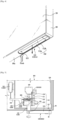
FIG. 3 shows a stand unit of the display device with a stand member pulled in, according to the first embodiment of the disclosure; -
FIG. 4 is a bottom perspective view of the display device with the stand member pulled in, according to the first embodiment of the disclosure; -
FIG. 5 shows the stand unit of the display device with the stand member partially pulled out, according to the first embodiment of the disclosure; -
FIG. 6 is a bottom perspective view of the display device with the stand member partially pulled out, according to the first embodiment of the disclosure; -
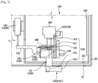
FIG. 7 shows the stand unit of the display device with the stand member fully pulled out, according to the first embodiment of the disclosure; -
FIG. 8 is a bottom perspective view of the display device with the stand member fully pulled out, according to the first embodiment of the disclosure; -
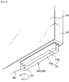
FIG. 9 shows a stand unit of a display device with a stand member pulled in, according to a second embodiment of the disclosure; -
FIG. 10 is a bottom perspective view of the display device with the stand member pulled in, according to the second embodiment of the disclosure; -
FIG. 11 shows the stand unit of the display device with the stand member partially pulled out, according to the second embodiment of the disclosure; -
FIG. 12 is a bottom perspective view of the display device with the stand member partially pulled out, according to the second embodiment of the disclosure; -
FIG. 13 shows the stand unit of the display device with the stand member fully pulled out, according to the second embodiment of the disclosure; -
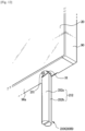
FIG. 14 is a bottom perspective view of the display device with the stand member fully pulled out, according to the second embodiment of the disclosure; -
FIG. 15 shows a stand unit of a display device with a stand member pulled in, according to a third embodiment of the disclosure; -
FIG. 16 is a bottom perspective view of the display device with the stand member pulled in, according to the third embodiment of the disclosure; -
FIG. 17 shows the stand unit of the display device with the stand member partially pulled out, according to the third embodiment of the disclosure; -
FIG. 18 is a bottom perspective view of the display device with the stand member partially pulled out, according to the third embodiment of the disclosure; -
FIG. 19 shows the stand unit of the display device with the stand member fully pulled out, according to the third embodiment of the disclosure; -
FIG. 20 is a bottom perspective view of the display device with the stand member fully pulled out, according to the third embodiment of the disclosure; -
FIG. 21 is a rear perspective view of a display device with a stand member pulled in, according to a fourth embodiment of the disclosure; -
FIG. 22 is a rear perspective view of the display device with the stand member pulled in, according to the fourth embodiment of the disclosure; -
FIG. 23 is a rear perspective view of the display device with the stand member fully pulled out, according to the fourth embodiment of the disclosure; -
FIG. 24 is a rear perspective view of a display device with a stand member pulled in, according to a fifth embodiment of the disclosure; -
FIG. 25 is a rear perspective view of a display device with a stand member pulled out, according to the fifth embodiment of the disclosure; -
FIG. 26 is a rear perspective view of the display device with the stand member fully pulled out, according to the fifth embodiment of the disclosure. - Embodiments and features as described and illustrated in the present disclosure are only preferred examples, and various modifications thereof may also fall within the scope of the disclosure.
- Throughout the drawings, like reference numerals refer to like parts or components.
- The terminology used herein is for the purpose of describing particular embodiments only and is not intended to limit the disclosure. It is to be understood that the singular forms "a," "an," and "the" include plural references unless the context clearly dictates otherwise. It will be further understood that the terms "comprises" and/or "comprising," when used in this specification, specify the presence of stated features, integers, steps, operations, elements, and/or components, but do not preclude the presence or addition of one or more other features, integers, steps, operations, elements, components, and/or groups thereof.
- The terms including ordinal numbers like "first" and "second" may be used to explain various components, but the components are not limited by the terms. The terms are only for the purpose of distinguishing a component from another. Thus, a first element, component, region, layer or chamber discussed below could be termed a second element, component, region, layer or section without departing from the teachings of the present disclosure. Descriptions shall be understood as to include any and all combinations of one or more of the associated listed items when the items are described by using the conjunctive term "∼ and/or ∼," or the like.
- Reference will now be made in detail to embodiments, examples of which are illustrated in the accompanying drawings, wherein like reference numerals refer to the like elements throughout.
-
FIG. 1 is a perspective view of a display device, according to a first embodiment of the disclosure, andFIG. 2 is an exploded perspective view of the display device, according to the first embodiment of the disclosure. - While the following description will focus on a
flat display device 1, embodiments of the disclosure may be applied to bendable display devices as well. Although a passively light-emitting display will be focused in the following description, it is, of course, possible that embodiments of the disclosure may be applied to an actively light-emitting display. - The terms 'forward' and 'front' are defined with respect to the a
display panel 20 of thedisplay device 1 shown inFIG. 1 , i.e., the front side of thedisplay panel 20 on which an image is displayed. The terms 'top (or upper side)' and 'bottom (or lower side)' indicates top and bottom of thedisplay device 1 shown inFIG. 1 , respectively, and 'both sides' and 'sideways (or laterally)' refer to the horizontal direction of thedisplay device 1. - The
display device 1 may include a display module for displaying an image. - The
display device 1 may include a chassis assembly that accommodates and supports thedisplay panel 20 and a backlight unit. - The
display panel 20 may include a liquid crystal panel formed of liquid crystals (not shown) enclosed between two glass panels (not shown) each having an electrode, and display an image on the front. - The chassis assembly may include a top chassis 82, a middle mold 70, and a
bottom chassis 84. - The top chassis 82 may include an
opening 82a to disclose thedisplay panel 20. Thebottom chassis 84 may include abottom part 84a arranged under the backlight unit, and abottom side part 84b extending upward from thebottom part 84a. - Many different components of the
display device 1, such as the top chassis 82 and the middle mold 70 may be supported on thebottom chassis 84. - The
bottom chassis 84 may serve to radiate heat generated from alight source 31 to the outside. Specifically, the heat generated from thelight source 31 may be conveyed to thebottom chassis 84 through a printed circuit board (PCB) 32, and radiated from thebottom chassis 84. For this, thebottom chassis 84 may be formed of aluminum, various metals such as SUS, or plastics such as ABS, which has good heat conductivity. Also for the PCB 32, a metal such as aluminum with good heat conductivity may be used. - In another embodiment, however, at least one of the top chassis 82, the middle mold 70, and the
bottom chassis 84 may be omitted or integrated with another. - The
display device 1 may further include arear cover 90 for covering the chassis assembly to protect and accommodate the chassis assembly and covering the rear side of thebottom chassis 84. - The
display device 1 may further include a backlight unit provided to supply light to thedisplay panel 20. - In the embodiment, the backlight unit may be of a direct type in which the
light source 31 is arranged right beneath thedisplay panel 20. The backlight unit may include alight source module 30 that includes thelight source 31 and the PCB 32 with the light source mounted thereon, and variousoptical sheets 50 arranged in a traveling path of light radiated from thelight source 31. - The
light source 31 may be provided to supply light to thedisplay panel 20. Thelight source 31 may include light emitting diodes (LEDs). The LEDs may be provided in a package in which an LED chip is mounted on a substrate and which is filled with resins. Unlike this, in another embodiment, a cold cathode fluorescent lamp (CCFL) or an external electrode fluorescent lamp (EEFL) may be used for the light source. - A plurality of
light sources 31 may be mounted on the PCB 32 at certain intervals. For example, a circuit pattern to convey driving power and signals to thelight sources 31 may be formed on the PCB 32. The PCB 32 may be safely arranged on thebottom chassis 84. - Light output from the
light source 31 may be directly supplied to thedisplay panel 20 unlike in an edge type display device. It is not limited thereto, and therear cover 90, and astand member 200, which will be described later, of thedisplay device 1 according to the disclosure may also be applied in an edge-type display device. - In this regard, to improve optical characteristics of light output from the
light source 31, theoptical sheet 50 may be arranged between thelight source 31 and thedisplay panel 20. - The backlight unit may include a
diffusion sheet 40. Thediffusion sheet 40 may cancel or minimize light irradiated from thelight source 31. The light irradiated from thelight source 31 comes directly into human eyes, making the pattern in which thelight source 31 is arranged visible as it is, and hence the diffusion sheet is used to cancel or minimize this effect. - Typically, the
diffusion sheet 40 is included in theoptical sheet 50 as a part of theoptical sheet 50. Thediffusion sheet 40 may be provided to diffuse the light irradiated from thelight source module 30 to all directions so as to uniformly cast the light in all directions on an image. - The backlight unit may further include a
reflector sheet 60 for reflecting light to prevent loss of light. Thereflector sheet 60 may reflect light irradiated from thelight source 31 to be incident on thediffusion sheet 40. Thereflector sheet 60 may have various forms, such as a sheet, a film, a plate, etc. For example, thereflector sheet 60 may be formed by coating a base material with a highly reflective material. SUS, brass, aluminum, PET, etc., may be used for the base material, and silver, TiO2, etc., may be used as a highly reflective coating agent. Thereflector sheet 60 may be safely seated and supported on the PCB 32. - The
rear cover 90 may cover the edges of thedisplay device 1 while covering the rear side of thebottom chassis 84 as described above. It is not limited thereto, and the edges of thedisplay device 1 may be covered by an additional frame or housing. However, in the following description, it will be assumed that the edges (or frames) of thedisplay device 1 are covered by therear cover 90. - Moreover, a direct-type display device will be taken as an example in describing the following embodiments of the disclosure, but embodiments of the disclosure are not limited thereto, and may also be applied to an edge-type display device.
- The
display device 1 may be installed on the wall (a mount type), or placed on the floor with a stand (a stand-type), depending on needs of the user. - On an occasion when a conventional display device is installed on the wall, a stand that otherwise supports the display device needs to be kept somewhere separately, in which case the stand might happen to be lost.
- For example, the user may install the display device in the mount-type or the stand-type for the space, and a problem may arise when the installation of the display device is to be changed from the mount-type to the stand-type and the stand having thus far been kept separately is lost.
- To solve this problem, the
display device 1 according to embodiments of the disclosure may include a stand unit 100 (which has a space which can be referred to as stand compartment) that includes astand 110 to support thedisplay device 1. Thestand unit 100 is coupled with thedisplay device 1 to prevent the problem of losing thestand 110. - Specifically, the
display device 1 may include thestand unit 100, and in a case of installing thedisplay device 1 on the wall, thestand 110 is pulled into thedisplay device 1, and in a case of placing thedisplay device 1 on the floor, thestand 110 may be pulled out of thedisplay device 1 to support thedisplay device 1 from the floor. - There may be two stand units 100L and 100R on the left and right of the
display device 1. Therear cover 90 may include two through holes, one of which is denoted by91, for the stand units 100L and 100R to pass through, respectively. The stand units 100L and 100R are arranged in the same configuration on the left and right of thedisplay device 1, so for convenience of explanation, one of the stand units 100L and 100R will be focused to describe thestand unit 100. Moreover, thestand unit 100 is not limited thereto, but may be provided in two or more. - The
stand unit 100 of thedisplay device 1 according to a first embodiment of the disclosure will now be described in detail. -
FIG. 3 shows the stand unit of the display device with the stand member pulled in, according to the first embodiment of the disclosure,FIG. 4 is a bottom perspective view of the display device with the stand member pulled in, according to the first embodiment of the disclosure,FIG. 5 shows the stand unit of the display device with the stand member partially pulled out, according to the first embodiment of the disclosure,FIG. 6 is a bottom perspective view of the display device with the stand member partially pulled out, according to the first embodiment of the disclosure,FIG. 7 shows the stand unit of the display device with the stand member fully pulled out, according to the first embodiment of the disclosure, andFIG. 8 is a bottom perspective view of the display device with the stand member fully pulled out, according to the first embodiment of the disclosure. - The
stand unit 100 may include a rotation guide for rotating at least a portion of thestand 110 around a rotation shaft. - The rotation guide may be provided for the
stand 110 to support thedisplay device 1 by being engaged with the movement of thestand 110 by its self-weight to rotate at least a portion of thestand 110 when thestand 110 is pulled out of thedisplay device 1. - In the first to third embodiments as will be described later, the rotation guide is a general term of a collection of all components to rotate the stand 110 (e.g., an elastic member, a
gas cylinder 140, atransmitter 150, a restrictingmember 215, aguide projection 331, etc.), and in the following description, names of the components of the rotation guide will be mentioned. - The
stand unit 100 may be arranged between thebottom chassis 84 and the rear cover 90 (seeFIG. 2 ). For example, thestand unit 100 may be arranged between thebottom chassis 84 and therear cover 90 in an empty space having no electric parts arranged therein. Furthermore, thestand unit 100 may be coupled onto the rear side of thebottom chassis 84 or the front side of therear cover 90. - The
stand unit 100 may include acase 120 that receives or takes out thestand 110, and ahousing 130 fixed to thecase 120 for thestand 110 to be pulled in or out ofcase 120. - The
stand unit 100 may also include alocking device 160 to fix thestand 110 by locking thestand 110 to remain in a state of being received in thecase 120. - The
locking device 160 may be arranged on the top of thestand 110. At least a portion of thestand 110 may be put into and constrained by thelocking device 160, and accordingly, thestand 110 may be locked in thelocking device 160. - The
stand 110 may be locked in thelocking device 160 while being received in thecase 120. - The
locking device 160 may be provided to unlock thestand 110 when thestand 110 is pushed up. In other words, thelocking device 160 may lock or unlock thestand 110 based on pushing. - The
locking device 160 may be provided in the form of a push locking device such as a ratchet. In the first and other embodiments as will be described later, the locking device is assumed to be a ratchet. - When the
stand 110 is released from the locked state, thestand 110 may be moved down by its self-weight. Accordingly, thestand 110 may be pulled out of thecase 120. - When the
stand 110, which has been pulled out, is pushed up, thestand 10 is moved up again by the external force, and at least a portion of thestand 110 in turn pushes thelocking device 160 and accordingly, is constrained back in thelocking device 160, ending up with thestand 110 being pulled back into thecase 120 - In this way, the
stand 110 may be moved up or down, and fixed at a particular position by thelocking device 160. Specifically, a highest position to which thestand 110 may be moved up may be defined by thelocking device 160, and a lowest position to which thestand 10 may be moved down may be defined by astopper 170, which will be described later. - The
stand 110 may then be moved between the highest position and the lowest position. Thestand 110 may be vertically moved by a certain distance that is set by the highest and lowest positions. - The
case 120 may have the form of a box with six faces, and include anopening 121 on the bottom side that is opened vertically for thestand 110 to be vertically moved through theopening 121. - The
opening 121 may be formed to be equal to or greater than the cross-sectional area of a supportingportion 112 of thestand 110 for the supportingportion 112 to pass through theopening 121. - A face of the
case 120 is formed to be openable (seeFIG. 3 ), so that the components of thestand unit 100 including thestand 110 may be safely placed inside thecase 120. Thecase 120 is not limited to having the form as in the first embodiment, but may have the form of a quadrangular frame opened to the front and back, in which case thehousing 130 may be directly coupled onto the rear side of thebottom chassis 84 or the front side of therear cover 90. Thecase 120 still is not limited thereto, but may have any other form. - The
housing 130 may be provided for thestand 110 to pass through. Thehousing 130 may include amovable housing stand 110 to be movable in the vertical direction, and a fixedhousing 133 fixed to thecase 120. - The
movable housing housing 133, i.e., movable while coupled with the fixedhousing 133. - Since the
stand 110 may be coupled with themovable housing housing 133 through themovable housing 131. Hence, thehousing 130 may prevent deviation of thestand 110 from thecase 120 while thestand 110 is moving. - The
movable housing stand housing 131 through which thestand 110 passes, and a combininghousing 132 with which agear portion 180 or thetransmitter 150, which will be described later, may be coupled. - The
stand unit 100 may include thestopper 170 to restrict vertical movement of thestand 110 and themovable housing stopper 170 may restrict movements of thestand 110 and themovable housing stand 110 and themovable housing - A
contact 132a may be provided in a portion of themovable hosing movable housing stopper 170 when moving down a certain distance. Specifically, thecontact 132a may be provided to protrude from a side of the combininghousing 132 toward a direction in which thestopper 170 extends. - Although not shown, the fixed
housing 133 may include a guide (not shown) for guiding the movement of thestand 110 andmovable housing stand 110 and themovable housing stand 110 and themovable housing - The
stand 110 may be moved down until thecontact 132a contacts thestopper 170, and in the state of contact between thestopper 170 and thecontact 132a, thestand 110 is restricted by thestopper 170 from moving down. - The
stand 110 may include abody portion 111, a lockedportion 114 arranged on the top of thebody portion 111 and inserted to and constrained by alocking device 160, and the supportingportion 112 provided to be pulled out of thedisplay device 1 when thestand 110 is unlocked and thus to support thedisplay device 110 from the floor. - The
stand unit 100 includes agas cylinder 140. Thegas cylinder 140 may be provided to contract or expand by being engaged with vertical movement of thestand 110. - The
gas cylinder 140 may transmit force created from the contraction or the expansion to thestand 110 for the supportingportion 112 to be rotated in a state of being pulled from thedisplay device 1. This will be described in more detail later. - The
stand unit 100 may include thetransmitter 150 for transmitting the force created by thegas cylinder 140 to thestand 110. Thestand unit 100 may further include thegear portion 180 driven by thetransmitter 150. - Specifically, the force created by the
gas cylinder 140 may rotate thegear portion 180 via thetransmitter 150. - The
stand 110 may include astand gear 115 arranged in thebody portion 111 and is engaged in gear with thegear portion 180. Accordingly, when thegear portion 180 is rotated, thestand gear 115 may be rotated in gear with thegear portion 180, and hence thebody portion 111 may be rotated as well. - When the
body portion 111 is rotated, the supportingportion 112 arranged beneath and engaged with thebody portion 111 is rotated, which will be described later. - A process in which the
stand 110 is pulled in or out by thestand unit 100 will now be described in detail. - As shown in
FIGS. 3 and4 , when thedisplay device 1 is in a packaged state or installed on the wall in the mount-type, thestand 110 may be placed in a pull-inposition 110A. - When the
stand 110 is placed in the pull-inposition 110A, themovable housing transmitter 150 engaged with thestand 110 may be in positions corresponding to the pull-inposition 110A of thestand 110. - The
gas cylinder 140 is connected to thetransmitter 150, and thegas cylinder 140 may go into a contraction state 140A as thetransmitter 150 is in a position corresponding to the highest position of thestand 110. - Specifically, the
gas cylinder 140 may contract or expand while the gas cylinder is fixed to thecase 120 and a piston of thegas cylinder 140 engaged with thetransmitter 150 moves vertically. - When the
stand 110 is placed in the pull-inposition 110A, it lies inside thecase 120 ordisplay device 1 and is not exposed. - A through
hole 91 is arranged on therear side 90a of therear cover 90 for thestand 110 to pass through in the vertical direction. The throughhole 91 may be formed to be equal to or greater than the cross-sectional area of the supportingportion 112 of thestand 110 for the supportingportion 112 to pass through the throughhole 91. - A shape of the through
hole 91 may match the shape of the supportingportion 112. - When the
stand 110 is placed in the pull-inposition 110A, it is not pulled out of the throughhole 91 and thus, not exposed, but it is possible for the user to push thestand 110 upward through the throughhole 91 from the outside. - The user may push the
stand 110 upward to pull thestand 110 out of thedisplay device 1. - When the
stand 110 is pushed up, the lockedportion 114 inserted to thelocking device 160 may be moved up to push thelocking device 160 from inside thelocking device 160. - As the
locking device 160 is pushed, the lockedportion 114 may be unlocked, and thestand 110 may be unlocked accordingly. - The
stand 110 may move down by its self-weight. - As shown in
FIGS. 5 and6 , thestand 110 and themovable housing portion 112 may pass through theopening 121 of thecase 120 and the throughhole 91 of therear cover 90 and may be pulled down from thedisplay device 1. - Hence, the
stand 110 may be placed in amiddle position 110B by moving down from the pull-inposition 110A. - As described above, the
movable housing transmitter 150 andgear portion 180 coupled with the combininghousing 132 may also be engaged and moved down with thestand 110. - As the
transmitter 150 is moved down, the piston of thegas cylinder 140 engaged with thetransmitter 150 is moved down, and hence, thegas cylinder 140 may go into the expansion state B. - The supporting
portion 112 may include afirst supporter 112a and asecond supporter 112b. - The
stand 110 may include arotation shaft 113 provided for the first andsecond supporters - The
rotation shaft 113 may extend in an extending direction of thestand 110, and may be arranged in the extending direction of thestand 110. - The first and
second supporters rotation shaft 113. Since therotation shaft 113 vertically extends in the extending direction of thestand 110, as described above, the first andsecond supporters - When the
stand 110 is placed in the pull-inposition 110A, the first andsecond supporters hole 91 and theopening 121 while contacting each other. - As described above, the through
hole 91 or theopening 121 is formed to have a shape matching the shape of thesupporter 112 and have a cross section in a similar size to thesupporter 112, so that the throughhole 91 or theopening 121 may keep the first andsecond supporters - In this case, horizontal rotation of the first or
second supporter rotation shaft 113 may be restricted by the throughhole 91 or theopening 121. - On the other hand, when the
stand 110 is placed in themiddle position 110B, the supportingportion 112 is pulled from the throughhole 91 and theopening 121, and the first andsecond supporters - Hence, when the
stand 110 is placed in themiddle position 110B, the first andsecond supporters - Since the
gas cylinder 140 is in the expansion state B, thegas cylinder 140 creates force by contraction and expansion, and the force may drive thegear portion 180 via thetransmitter 150. - As the
gear portion 180 is driven, thestand gear 115 in gear with the gear portion 185 may be rotated, and thebody portion 111 may be rotated by being engaged with the rotation with thestand gear 115. - The supporting
portion 112 coupled with thebody portion 111 may be engaged with rotation of thebody portion 111 for the first andsecond supporters - The
gear portion 180 may control rotation speed of the first andsecond supporters gear portion 180, and the rotation speed of the first andsecond supporters - Furthermore, the
gear portion 180 may help the supportingportion 112 rotate stably, and, as described above, control the rotation speed, thereby increasing reliability and beauty of the supportingportion 112 when the supportingportion 112 is rotated. - Although not shown, the
stand 110 may include an elastic member provided to rotate the first andsecond supporters - The elastic member may be provided to rotate the first and
second supporters stand 110 is placed in themiddle position 110B by pushing the first andsecond supporters - The elastic member may be formed with a member such as a torsion spring.
- Even when the elastic member pushes each of the first and
second supporters stand 110 is placed in the pull-inposition 110A, thesupporters case 120 while staying in contact with each other because the supportingportion 112 is received in the throughhole 91 oropening 121 as described above. - When the
stand 110 is placed in themiddle position 110B, the elastic member may push the first andsecond supporters - The elastic member may be arranged to apply torque onto the first and
second supporters rotation shaft 113 as a rotation axis. - When elastic force of the elastic member is enough to push the first and
second supporters stand unit 100 may not include some components such as theaforementioned gas cylinder 140 andtransmitter 150. - The
stand unit 100 may rotate the supportingportion 112 simply with the elastic member. - The
stand unit 100 is not limited to what is described in the first embodiment, and may rotate the supportingportion 112 just with the force of thegas cylinder 140. - Referring to
FIGS. 7 and8 , rotation force is applied to the supportingportion 112 and the first andsecond supporters display device 1, respectively. - The position of the
stand 110 may be changed by rotation of the first andsecond supporters middle position 110B to a supportingposition 110C. - As the first and
second supporters rotation shaft 113 in opposite directions, the first andsecond supporters rotation shaft 113. - Accordingly, the
first supporter 112a may be placed in front of thedisplay device 1, and thesecond supporter 112b may be placed in the back of thedisplay device 1. - As the
stand 110 is placed in the supportingposition 110C, the supportingportion 112 may support thedisplay device 1 from front and back, thereby placing thedisplay device 1 stably on the floor with thestand 110 when thedisplay device 1 is installed in the stand-type. - In other words, the
display device 1 may be supported on the floor in the stand-type with thestand 110 pulled out and placed in the supportingposition 110C, and thedisplay device 1 may be supported on the wall in the mount-type by pulling thestand 110 into thedisplay device 1 in the pull-inposition 110A. - The user may pull the
stand 110 back into thedisplay device 1 from the supportingposition 110C by reversing the aforementioned process. - Specifically, the user may push the unfolded first and
second supporters position 110C to be folded together, and push the supportingportion 112 upward to move thestand 110 upward, thereby forcing the lockedportion 114 of thestand 110 to be inserted back into thelocking device 160 and constrained by thelocking device 160. - When the
stand 110 is locked in thelocking device 160, thestand 110 is placed back in the pull-inposition 110A and not exposed. - In this way, the
stand unit 100 may selectively pull thestand 110 into or out of thedisplay device 1. Accordingly, even in a situation where thedisplay device 1 is to be installed in the mount-type that does not require thestand 110, thestand 110 may be pulled into thedisplay device 1, thereby eliminating the need to keep thestand 110 separately and concerns about losing thestand 110. - Furthermore, as described above, the user may pull the
stand 110 out of thedisplay device 1 by simply pushing the inner side of the throughhole 91 formed at the bottom of thedisplay device 1. - When the conventional display device is placed in the stand-type, the display device needs to be held by something or be laid on the floor to attach a stand onto the display device. After the stand is attached onto the display device, the user needs to hold and stand the display device on the floor in the stand-type.
- On the contrary, the
display device 1 according to the first embodiment of the disclosure may be easily installed on the floor with thestand unit 100 that allows the user to pull a stand out of thedisplay device 1 by pushing the bottom of thedisplay device 1 while holding thedisplay device 1. - A second embodiment of the disclosure will now be described. Description of overlapping components with those of the first embodiment will not be repeated.
-
FIG. 9 shows a stand unit of a display device with a stand member pulled in, according to a second embodiment of the disclosure,FIG. 10 is a bottom perspective view of the display device with the stand member pulled in, according to the second embodiment of the disclosure,FIG. 11 shows the stand unit of the display device with the stand member partially pulled out, according to the second embodiment of the disclosure,FIG. 12 is a bottom perspective view of the display device with the stand member partially pulled out, according to the second embodiment of the disclosure,FIG. 13 shows the stand unit of the display device with the stand member fully pulled out, according to the second embodiment of the disclosure, andFIG. 14 is a bottom perspective view of the display device with the stand member fully pulled out, according to the second embodiment of the disclosure. - In the second embodiment, a
stand unit 200 may include astand 210 provided to be movable in the vertical direction, acase 220, and ahousing 230 fixed to thecase 220 to pull thestand 210 in or out of thecase 220. - The
stand unit 200 may also include alocking device 260 to fix thestand 210 by locking thestand 210 to remain in a state of being received in thecase 220. - The
locking device 260 may be arranged on the top of thestand 210. At least a portion of thestand 210 may be put into and constrained by thelocking device 260, and accordingly, thestand 210 may be locked in thelocking device 260. - When the
stand 210 is released from the locked state, thestand 210 may be moved down by its self-weight. Accordingly, thestand 210 may be pulled out of thecase 220. - When the
stand 210, which has been pulled out, is pushed up, thestand 10 is moved up again by the external force, and at least a portion of thestand 210 in turn pushes thelocking device 260 and accordingly, is constrained back in thelocking device 260, ending up with thestand 210 being pulled back into thecase 220. - In this way, the
stand 210 may be moved up or down, and fixed at a particular position by thelocking device 260. Specifically, a highest position to which thestand 210 may be moved up may be defined by thelocking device 260, and a lowest position to which thestand 10 may be moved down may be defined by astopper 270. - The
stand 110 may then be moved between the highest position and the lowest position. Thestand 110 may be vertically moved by a certain distance that is set by the highest and lowest positions. - The
housing 230 may include amovable housing 231 through which thestand 210 passes and which is engaged with thestand 210 to be movable in the vertical direction, and a fixedhousing 232 fixed to thecase 220. - The
movable housing 231 may be movable against the fixedhousing 232, i.e., movable in a state of being coupled with the fixedhousing 232. - The
stand unit 200 may further include aguide 240 for guiding vertical movement of thestand 210 and themovable housing 231. - The
guide 240 may include arack 241 extending vertically, and apinion 242 coupled in gear with therack 241 and arranged in themovable housing 231. - As the pinion is moved along the
rack 241 that extends vertically, themovable housing 231 coupled to thepinion 242 and thestand 210 coupled to themovable housing 231 may be stably moved in the vertical direction. - The
stand 210 may include abody portion 211, a lockedportion 214 arranged on the top of thebody portion 211 and inserted to and constrained by alocking device 260, and the supportingportion 212 provided to be pulled out of thedisplay device 1 when thestand 210 is unlocked and thus to support thedisplay device 1 from the floor. - The
stand 210 may include a restrictingmember 215 for constraining the supportingportion 212. When thestand 210 is pulled out of thedisplay device 1, the restrictingmember 215 may release the supportingportion 212 from the constraint to be unfolded. When thestand 210 is moved inside thedisplay device 1, the restrictingmember 215 may constrain the supportingportion 212 for thestand 210 to be stably moved inside thedisplay device 1. - A process in which the
stand 210 is pulled in or out by thestand unit 200 will now be described in detail. - As shown in
FIGS. 9 and10 , when thedisplay device 1 is in a packaged state or installed on the wall in the mount-type, thestand 210 may be placed in a pull-inposition 210A. - When the
stand 210 is placed in the pull-inposition 210A, themovable housing 231 engaged with thestand 210 may be in a position corresponding to the pull-inposition 210A of thestand 110. - When the
stand 210 is placed in the pull-inposition 210A, it lies inside thecase 220 ordisplay device 1 and is not exposed. - When the
stand 210 is placed in the pull-inposition 210A, it is not pulled out of the throughhole 91 and thus, not exposed, but it is possible for the user to push thestand 210 upward through the throughhole 91 from the outside. - The user may push the
stand 210 upward to pull thestand 210 out of thedisplay device 1. - When the
stand 210 is pushed up, the lockedportion 214 inserted to thelocking device 260 may be moved up to push thelocking device 260 from inside thelocking device 260. - As the
locking device 260 is pushed, the lockedportion 214 may be unlocked, and thestand 210 may be unlocked accordingly. - The
stand 210 may move down by its self-weight. - As shown in
FIGS. 11 and12 , thestand 210 and themovable housing 231 may move down by their self-weights, and accordingly, the supportingportion 212 may pass through anopening 221 of thecase 220 and the throughhole 91 of therear cover 90 and may be pulled down from thedisplay device 1. - Hence, the
stand 210 may be placed in amiddle position 210B by moving down from the pull-inposition 210A. - The supporting
portion 212 may include afirst supporter 212a and asecond supporter 212b. Thefirst supporter 212a may be placed in front of thedisplay device 1, and thesecond supporter 212b may be placed in the back of thedisplay device 1. - The
stand 210 may include arotation shaft 213 provided for the first andsecond supporters - The
rotation shaft 213 may extend in a direction parallel to the length of thedisplay device 1. Specifically, therotation shaft 213 may extend in the horizontal direction of thedisplay device 1 and may be arranged in the horizontal direction of thedisplay 1. - The first and
second supporters rotation shaft 213. Since therotation shaft 213 extends in the horizontal direction of thedisplay device 1, as described above, the first andsecond supporters display device 1. - Specifically, the
first supporter 212a may be turned to the front of thedisplay device 1, and thesecond supporter 212b may be turned to the back of thedisplay device 1. - When the
stand 210 is placed in the pull-inposition 210A, the first andsecond supporters hole 91 and theopening 121 while contacting each other. The throughhole 91 or theopening 121 may keep the first andsecond supporters - On the other hand, when the
stand 210 is placed in themiddle position 210B, the supportingportion 212 is pulled from the throughhole 91 and theopening 121, and the first andsecond supporters - Hence, when the
stand 210 is placed in themiddle position 210B, the first andsecond supporters - Although not shown, the
stand 210 may include an elastic member provided to rotate the first andsecond supporters - The elastic member may be provided to rotate the first and
second supporters stand 210 is placed in themiddle position 210B by pushing the first andsecond supporters - The elastic member may be formed with a member such as a torsion spring.
- Even when the elastic member pushes each of the first and
second supporters stand 210 is placed in the pull-inposition 210A, the first andsecond supporters case 220 while staying in contact with each other because the supportingportion 212 is received in the throughhole 91 oropening 121 as described above. - When the
stand 210 is placed in themiddle position 210B, the elastic member may push the first andsecond supporters - The elastic member may be arranged to be able to apply torque onto the first and
second supporters rotation shaft 213 as a rotation axis. - The
stand 210 may include a restrictingmember 215 to constrain the first andsecond supporters member 215 may restrict the first andsecond supporters position 210A or themiddle position 210B. - Specifically, while the
stand 210 is moving between the pull-inposition 210A and themiddle position 210B, the restrictingmember 215 may constrain the first andsecond supporters stand 210 to be moved stably. - Although not shown, the restricting
member 215 is provided to be hooked with the first andsecond supporters body portion 211. It is not, however, limited thereto, but the restrictingmember 215 may be provided in various forms to constrain or release the first andsecond supporters - The
stand unit 200 further includes a gas cylinder to push the supportingportion 212 to rotate the first andsecond supporters - The gas cylinder's main body may be fixed to the
case 220 and a piston of the gas cylinder may be engaged with themovable housing 231 to be moved. - Accordingly, the gas cylinder may contract or expand as the
stand 210 and themovable housing 231 are moved vertically, and the force created from the contraction or expansion may be transmitted to the supportingportion 212 to rotate each of the first andsecond supporters - With the gas cylinder included in the
stand unit 200, the elastic member may not be included in thestand unit 200. - The
guide 240 may guide the moving direction of thestand 210 through therack 241 and thepinion 242 and simultaneously, control the moving speed of thestand 210. For example, the speed at which thestand 210 moves up or down may be controlled by adjusting the size or arrangement of therack 241 andpinion 242. - Furthermore, the
guide 240 may be provided to allow thestand 210 to be stably moved in gear with therack 241 and thepinion 242, and may increase reliability and beauty of thestand 210 by controlling the rising or falling speed as described above. - Referring to
FIGS. 13 and14 , rotation force is applied to the supportingportion 212 and the first andsecond supporters display device 1, respectively. - When the
movable housing 231 is restricted by thestopper 270 from moving downward, thebody portion 211 of thestand 210 that is moved by being engaged with themovable housing 231 may be restricted from moving as well. - The restricting
member 215 arranged inside thebody portion 211 is not constrained by this but may be moved by its self-weight further down than thebody portion 211 is. - The restricting
member 215 may vertically slide in thebody portion 211. The restrictingmember 215 may be moved down and constraints of the restrictingmember 215 on the first andsecond supporters - The restricting
member 215 releases constraints on the first andsecond supporters movable housing 231 is restricted by thestopper 270 from moving, and hence the first andsecond supporters stand 210 to be finally in the supportingposition 210C. - As the first and
second supporters rotation shaft 213 in opposite directions, the first andsecond supporters rotation shaft 213. - Accordingly, the
first supporter 212a may be placed in front of thedisplay device 1, and thesecond supporter 212b may be placed in the back of thedisplay device 1. - A third embodiment of the disclosure will now be described. Description of overlapping components with those of the previous embodiments will not be repeated.
-
FIG. 15 shows a stand unit of a display device with a stand member pulled in, according to a third embodiment of the disclosure,FIG. 16 is a bottom perspective view of the display device with the stand member pulled in, according to the third embodiment of the disclosure,FIG. 17 shows the stand unit of the display device with the stand member partially pulled out, according to the third embodiment of the disclosure,FIG. 18 is a bottom perspective view of the display device with the stand member partially pulled out, according to the third embodiment of the disclosure,FIG. 19 shows the stand unit of the display device with the stand member fully pulled out, according to the third embodiment of the disclosure, andFIG. 20 is a bottom perspective view of the display device with the stand member fully pulled out, according to the third embodiment of the disclosure. - In the third embodiment, the stand unit 300 may include a
stand 310 provided to be movable in the vertical direction, acase 320, and ahousing 330 fixed to thecase 310 to allow thestand 310 to be pulled in or out of thecase 320. - The stand unit 300 may also include a
locking device 360 to fix thestand 310 by locking thestand 310 to remain in a state of being received in thecase 320. - The
locking device 360 may be arranged on the top of thestand 310. At least a portion of thestand 310 may be put into and constrained by thelocking device 360, and accordingly, thestand 310 may be locked in thelocking device 360. - When the
stand 310 is released from the locked state, thestand 310 may be moved down by its self-weight. Accordingly, thestand 310 may be pulled out of thecase 320. - When the
stand 310, which has been pulled out, is pushed up, thestand 310 is moved up again by the external force, and at least a portion of thestand 310 in turn pushes thelocking device 360 and accordingly, is constrained back in thelocking device 360, ending up with thestand 310 being pulled back into thecase 320. - The
housing 330 may include afirst housing 330a coupled with thecase 320 and asecond housing 330b coupled with thefirst housing 330a. Certain space may be formed between the first andsecond housings stand 310 to be inserted thereto. - The
stand 310 is inserted to the certain space, and the first and second housings 320a and 320b may be combined. Thestand 310 may be moved vertically in the certain space. - The
stand 310 may include abody portion 311 inserted to thehousing 330, a lockedportion 314 arranged on the top of thebody portion 311 and inserted to and constrained by alocking device 360, and the supportingportion 312 provided to be pulled out of thedisplay device 1 when thestand 310 is unlocked and thus support thedisplay device 1 from the floor. - The
second housing 330b may include aguide projection 331 for guiding movement of thebody portion 311. It is not, however, limited thereto, and theguide projection 331 may be arranged in thefirst housing 330a in another embodiment. - The
body portion 331 may include arail 316 to which theguide projection 331 is inserted. Thebody portion 331 may be vertically moved while theguide projection 331 is inserted to therail 316. - Accordingly, the
body portion 331 may be moved along the direction in which therail 316 extends. - At least a portion of the
rail 316 may extend straight vertically, and some other portion of therail 316 may be curved in the vertical direction. - Hence, the
body portion 331 may be moved vertically when theguide projection 331 is in the straight portion of therail 316, and may be rotated along the curve of therail 316 when theguide projection 331 is in the curved portion. This will be described in more detail later. - A process in which the
stand 310 is pulled in or pulled out by the stand unit 300 will now be described in detail. - As shown in
FIGS. 15 and16 , when thedisplay device 1 is in a packaged state or installed on the wall in the mount-type, thestand 310 may be placed in a pull-inposition 310A. - When the
stand 310 is placed in the pull-inposition 310A, the supportingportion 312 may be located in a receiving groove 322 (seeFIG. 19 ) formed on the bottom side of thecase 320. - The supporting
portion 312 may be provided to be perpendicular to thebody portion 311, and when thestand 310 is placed in the pull-inposition 310A, may lie along the length of thedisplay device 1. - In other words, when the
stand 310 is placed in the pull-inposition 310A, the supportingportion 312 may lie in the horizontal direction of thedisplay device 1. - The receiving
groove 322 may also be formed to extend along the horizontal direction of thedisplay device 1. - When the
stand 310 is placed in the pull-inposition 310A, it lies inside thecase 320 ordisplay device 1 and is not exposed. - When the
stand 310 is placed in the pull-inposition 310A, it is not pulled out of the throughhole 91 and thus, not exposed, but it is possible for the user to push thestand 310 upward through the throughhole 91 from the outside. - The user may push the
stand 310 upward to pull thestand 310 out of thedisplay device 1. - When the
stand 310 is pushed up, the lockedportion 314 inserted to thelocking device 360 may be moved up to push thelocking device 360 from inside thelocking device 360. - As the
locking device 360 is pushed, the lockedportion 314 may be unlocked, and thestand 310 may be unlocked accordingly. - The
stand 310 may move down by its self-weight. - As shown in
FIGS. 17 and18 , thestand 310 may move down by the self-weight, and accordingly, the supportingportion 312 may be pulled out of the receivinggroove 322 of thecase 320 and may pass through the throughhole 91 of therear cover 90, and thebody portion 311 may be pulled down through the opening323 of thecase 320. - Hence, the
stand 310 may be placed in amiddle position 310B by moving down from the pull-inposition 310A. - While the
stand 310 is moving from the pull-inposition 310A to themiddle position 310B, theguide projection 331 may be placed in afirst area 316a of therail 316. Thefirst area 316a is an area in which therail 316 extends straight in the vertical direction. In thefirst area 316a, theguide projection 331 may guide thestand 310 for thebody portion 311 to be moved in the vertical direction. - The supporting
portion 312 may then be moved down by keeping the direction in which the supportingportion 312 lies that corresponds to the horizontal direction of thedisplay device 1. - Subsequently, when the
guide projection 331 is located in asecond area 316b of therail 316, thebody portion 311 may be moved down by being rotated in one direction along the curve of thesecond area 316b. The supportingportion 312 may be moved down by being engaged with thebody portion 311 and rotated in one direction. - Although not shown, the stand unit 300 may further include a gear portion coupled to the
body portion 311. The gear portion may include a plurality of gears, in which case at least one gear may be coupled to thebody portion 311 and at least another gear may be coupled to thehousing 330. - Moving speed of the
stand 310 may be controlled by the gear portion, enabling thestand 310 to be stably moved, thereby increasing reliability and beauty of thestand 310. - Referring to
FIGS. 19 and20 , when theguide projection 331 reaches anend 316c of thesecond area 316b of therail 316, theguide projection 331 may be stuck in therail 316 and thebody portion 311 may not move down any longer and keep the fallen state. - The
stand 310 may then be in a supportingposition 310C at which to support thedisplay device 1. - The supporting
portion 312 may be engaged with thebody portion 311 and rotated along the curve of therail 316, e.g., about 90 degrees in one direction. - In other words, the length and curvature of the curve of the
second area 316b may be adjusted such that thebody portion 311 may be rotated about 90 degrees until theguide projection 331 reaches theend 316c. - As the supporting
portion 312 is rotated about 90 degrees, the supportingportion 312 may lie in a direction from front to back of thedisplay device 1. Hence, the supportingportion 312 may stably support thedisplay device 1. - Although not shown, a stopper may be included to keep the state in which the
guide projection 331 and theend 316c come into contact with each other. - The stopper may be a section of the
rail 316 extending from theend 316c to the opposite for restricting theguide projection 331 from moving, and may be provided separately to press thebody portion 311 to restrict movement of thebody portion 311. - The
stand 310 may be rotated to change the direction in which the supportingportion 312 lies while moving from themiddle position 310B to the supportingposition 310C. - Hence, when the
stand 310 is placed in the supportingposition 310C, the stand unit 300 may place thestand 310 to support thedisplay device 1. - A fourth embodiment of the disclosure will now be described. Description of overlapping components with those of the previous embodiments will not be repeated.
-
FIG. 21 is a rear perspective view of a display device with a stand member pulled in, according to a fourth embodiment of the disclosure,FIG. 22 is a rear perspective view of the display device with the stand member pulled in, according to the fourth embodiment of the disclosure, andFIG. 23 is a rear perspective view of the display device with the stand member fully pulled out, according to the fourth embodiment of the disclosure. - In the fourth embodiment, the
display device 1 may include astand unit 400 that may be pulled in or out of arear side 90b' of a rear cover 90'. - The
stand unit 400 may include astand 410 provided to support thedisplay device 1 when thestand unit 400 is pulled out of the rear cover 90', ahinge part 420 provided for thestand 410 to be turned to a first direction or a second direction which is perpendicular to the first direction, and arotation shaft 430 provided for thestand 410 to be rotated in the first or second direction. - The
rotation shaft 430 may include afirst rotation shaft 431 provided for thestand 410 to be turned in the first direction, and asecond rotation shaft 432 provided for thestand 410 to be turned in the second direction. - The
first rotation shaft 431 may be provided to bore through thehinge part 420 and have both ends placed inside the rear cover 90'. - The
second rotation shaft 432 may be provided to bore through thestand 410 and thehinge part 420 for thestand 410 to be rotated against thehinge part 420. - The
hinge part 420 may be rotated by thefirst rotation shaft 431 against the rear cover 90'. Specifically, thehinge part 420 may be coupled with the rear cover 90' to be turned to the front and back of thedisplay device 1. - The
stand 410 may be coupled with thehinge part 420 to be rotated by thesecond rotation shaft 432 against thehinge part 420. Specifically, thehinge part 420 may be rotationally coupled with the rear cover 90' and thestand 410 may be rotationally coupled with thehinge part 420. - As shown in
FIG. 21 , thestand unit 400 may be in a pull-inposition 410A, when thedisplay device 1 is in a packaged state or installed on the wall in the mount-type. - When the
stand 410 is placed in the pull-inposition 410A, it lies inside the rear cover 90' ordisplay device 1 and is not exposed. - In the pull-in
position 410A, thestand 410 may be pulled into a receiving groove 92' formed on arear side 90b' of the rear cover 90'. - The
stand 410 is not pulled out of the receiving groove 92' and thus, not exposed, but it is possible for the user to pull out thestand 410 through the receiving groove 92'. - To pull the
stand 410 out of thedisplay device 1, the user may pull out thestand 410 from the receiving groove 92'. - When the
stand 410 is pulled out, it may be turned down around thefirst rotation shaft 431 by its self-weight. - Referring to
FIG. 22 , thestand 410 may be turned down by its self-weight, and thus pulled down from thedisplay device 1. - Hence, the
stand 410 may be placed in amiddle position 410B by moving down from the pull-inposition 410A. - When the
stand 410 is placed in themiddle position 410B, the user may turn thestand 410 around thesecond rotation shaft 432, in which case since thesecond rotation shaft 432 extends vertically, thestand 410 may be turned to the front and back of thedisplay device 1. - Although not shown, the
stand unit 400 may further include a gear portion arranged between thestand 410 and thehinge part 420. The gear portion may include a plurality of gears, in which case at least one gear may be coupled to thestand 410 and at least another gear may be coupled to thehinge part 420. - Moving speed of the
stand 410 may be controlled by the gear portion, enabling thestand 410 to be stably turned, thereby increasing reliability and beauty of thestand 410. - Referring to
FIG. 23 , thestand 410 is turned to the front and back of thedisplay device 1 to be in a supportingposition 410C at which to support thedisplay device 1. - The
stand 410 may be rotated about 90 degrees against thehinge part 420. - The
hinge part 420 may include a stopper (not shown) for thestand 410 to be rotated about 90 degrees against thehinge part 420. The stopper may restrict rotation of thestand 410 such that thestand 410 is not rotated more than about 90 degrees against thehinge part 420. - The
stand unit 400 may further include a stand check member (not shown) to prevent thestand 410 from being turned in the opposite direction after thestand 410 is turned about 90 degrees. - The stand check member may check rotation of the
stand 410 to prevent thestand 410 from being turned to any direction after thestand 410 is rotated 90 degrees against thehinge part 420, thereby enabling thestand 410 to stably support thedisplay device 1. - A fifth embodiment of the disclosure will now be described. Description of overlapping components with those of the previous embodiments will not be repeated.
-
FIG. 24 is a rear perspective view of the display device with the stand member pulled in, according to the fifth embodiment of the disclosure,FIG. 25 is a rear perspective view of the display device with the stand member pulled in, according to the fifth embodiment of the disclosure, andFIG. 26 is a rear perspective view of the display device with the stand member fully pulled out, according to the fifth embodiment of the disclosure. - In the fifth embodiment, the
display device 1 may include astand unit 500 that may be pulled in or out of arear side 90b" of arear cover 90". - The
stand unit 500 may include astand 510 provided to support thedisplay device 1 when thestand unit 500 is pulled out of therear cover 90", ahinge part 520 provided for thestand 510 to be turned, and arotation shaft 530 provided for thestand 510 to be turned. - Referring to
FIG. 24 , thestand 510 may be in a pull-inposition 510A, when thedisplay device 1 is in a packaged state or installed on the wall in the mount-type. - When the
stand 510 is placed in the pull-inposition 510A, it lies inside therear cover 90" ordisplay device 1 and is not exposed. - In the pull-in
position 510A, thestand 510 may be pulled into a first receivinggroove 94" formed on therear side 90b" of therear cover 90". - The
hinge part 520 and therotation shaft 530 may be pulled in asecond receiving groove 95" formed inside therear cover 90". - The
stand 510 is not pulled out of the first receivinggroove 94" and thus, not exposed, but it is possible for the user to pull out thestand 510 through the first receivinggroove 94". - To pull the
stand 510 out of thedisplay device 1, the user may push thestand 510 downward through the first receivinggroove 94". - The
stand 510 and thehinge part 520 may be integrally formed. Furthermore, therotation shaft 530 may penetrate thehinge part 520. Accordingly, thehinge part 520 and therotation shaft 530 may be moved down by being engaged with thestand 510. - In this case, the
hinge part 520 and therotation shaft 530 may be moved down along the second receivinggroove 95". - The
first receiving groove 94" may be formed on therear side 90b" of therear cover 90" to vertically extend to the bottom of therear cover 90". - The lower end of the first receiving
groove 94" may be cut. Thestand 510 may be rotated at the lower end of the first receivinggroove 94", as will be described below. - The
second receiving groove 95" may be formed inside therear cover 90" to extend vertically like the first receivinggroove 94". - Although not shown, there may be an anti-deviation member included to prevent the
stand 510 placed in the pull-inposition 510A from deviating from the pull-inposition 510A. Accordingly, thestand 510 may be prevented from sliding down from the pull-inposition 510A simply by external force. - Referring to
FIG. 25 , thestand 510 may slide down when pushed by the user, and may thus be pulled down from thedisplay device 1. - Hence, the
stand 510 may be placed in a middle position 510B by moving down from the pull-inposition 510A. - When the
stand 510 is placed in the middle position 510B, thehinge part 520 and therotation shaft 530 may be in the middle position 510B as well. - In the middle position 510B, the
rotation shaft 530 may be located at thelower end 95a" of the second receivinggroove 95". In this case where thestand 510 is placed in the middle position 510B, therotation shaft 530 reaches thelower end 95a" and is prevented from moving further down, and accordingly, thestand 510 may be restricted from moving further down from the middle position 510B. - Subsequently, the
stand 510 may be turned around therotation shaft 530 from the middle position 510B. Therotation shaft 530 may extend in the horizontal direction of thedisplay device 1. - Hence, the
stand 510 may be turned to the front and back of thedisplay device 1. - Although not shown, the
stand unit 500 may further include a rack-pinion section arranged between thestand 510 and the first receivinggroove 94". The rack-pinion section may include a rack and a pinion, at least one of which may be coupled with thestand 510 and the other of which may be coupled with the first receivinggroove 94". - Moving speed of the
stand 510 may be controlled by the rack-pinion section, enabling thestand 510 to slide stably, thereby increasing reliability and beauty of thestand 510. - It is not limited thereto, and instead of the rack-pinion section, a rail or some other structure may be arranged between the
stand 510 and the first receivinggroove 94" to guide sliding of thestand 510. - Referring to
FIG. 26 , thestand 510 is turned to the front and back of thedisplay device 1 to be in a supporting position 510C at which to support thedisplay device 1. - The
stand 510 may be rotated about 90 degrees from the pull-inposition 510A. - The
stand unit 500 may include a stopper (not shown) for thestand 510 to be rotated about 90 degrees from the pull-inposition 510A. The stopper may restrict rotation of thestand 510 such that thestand 510 may not be rotated more than about 90 degrees from the pull-inposition 510A. - The
stand unit 500 may further include a stand check member (not shown) to prevent thestand 510 from being turned in the opposite direction after thestand 510 is turned about 90 degrees from the pull-inposition 510A. - The stand check member may check rotation of the
stand 510 to prevent thestand 510 from being turned to any direction after thestand 510 is rotated 90 degrees, thereby enabling thestand 410 to stably support thedisplay device 1. - Several embodiments have been described above, but a person of ordinary skill in the art will understand and appreciate that various modifications can be made without departing from the scope of the present disclosure. Thus, it will be apparent to those ordinary skilled in the art that the true scope of technical protection is defined by the following claims.
Claims (7)
- A display device (1) comprising:a display panel (20) to display an image;a chassis (84) arranged on a back side of the display panel (20);a cover (90) formed with an opening (121), the cover covering a back side of the chassis and a bottom side of the chassis;a stand (110) to support the display device and being storable in an open space between the chassis and the cover;a locking device (160, 260, 360) to lock the stand in the open space to thereby store the stand within the display device and to release the stand from the open space; anda rotation guide,wherein the stand, the locking device, and the rotation guide are configured so that,when the stand is locked in the open space by the locking device and is thereby stored within the display device,the release of the stand from the open space by the locking device allows the stand to be pulled out of the display device through the opening by self-weight of the stand, and at least a portion of the stand to be rotated by the rotation guide, so that the stand is in position to support the display device,wherein the stand comprises:a body portion (111);a locked portion (114) arranged at the top of the body portion and locked in the locking device; anda supporting portion (112) arranged beneath the body portion and pulled out of the display device to support the display device when the stand is unlocked;wherein the supporting portion comprises a first supporter (112a), a second supporter (112b), and a rotation shaft (113), andthe first supporter and the second supporter are provided to contact each other when the stand is stored in the display device, and to be unfolded by being rotated around the rotation shaft when the stand is pulled out of the display device,characterized in that the display device further comprises:a stand compartment comprising a gas cylinder (140) provided to contract or expand by being engaged with vertical movement of the body portion, andthe gas cylinder is provided to apply pressure to the body portion to rotate the first supporter and the second supporter.
- The display device of claim 1, wherein the locking device is arranged at the top of the stand to release the stand from being locked by the locking device when the stand is pushed up, and to lock the stand when the stand is inserted to the locking device by being pushed up from being unlocked.
- The display device of claim 2, wherein the stand is moved down and pulled out of the display device when released by the locking device from being locked.
- The display device of claim 1, wherein the locking device is provided to lock or unlock the stand when the stand is pushed.
- The display device of claim 1, whereinthe stand compartment further comprises a transmitter (150) provided to transmit a force created by the gas cylinder to the body portion,the body portion comprises a gear portion (180) driven by the transmitter, and the gear portion is provided to be rotated to enable the first supporter and the second supporter to be rotated.
- The display device of claim 1, wherein the rotation shaft extends in a direction corresponding to a direction in which the body portion extends.
- The display device of claim 1, wherein the rotation shaft extends in a direction parallel to the length of the display panel.
Applications Claiming Priority (2)
| Application Number | Priority Date | Filing Date | Title |
|---|---|---|---|
| KR1020180114338A KR102521485B1 (en) | 2018-09-21 | 2018-09-21 | Display apparatus |
| PCT/KR2019/011996 WO2020060154A1 (en) | 2018-09-21 | 2019-09-17 | Display device |
Publications (4)
| Publication Number | Publication Date |
|---|---|
| EP3834052A1 EP3834052A1 (en) | 2021-06-16 |
| EP3834052A4 EP3834052A4 (en) | 2021-10-13 |
| EP3834052B1 true EP3834052B1 (en) | 2025-01-22 |
| EP3834052C0 EP3834052C0 (en) | 2025-01-22 |
Family
ID=69884231
Family Applications (1)
| Application Number | Title | Priority Date | Filing Date |
|---|---|---|---|
| EP19863113.7A Active EP3834052B1 (en) | 2018-09-21 | 2019-09-17 | Display device |
Country Status (5)
| Country | Link |
|---|---|
| US (1) | US10656671B2 (en) |
| EP (1) | EP3834052B1 (en) |
| KR (1) | KR102521485B1 (en) |
| CN (1) | CN112740139B (en) |
| WO (1) | WO2020060154A1 (en) |
Families Citing this family (6)
| Publication number | Priority date | Publication date | Assignee | Title |
|---|---|---|---|---|
| CN107134227B (en) * | 2017-07-17 | 2023-08-01 | 深圳市洲明科技股份有限公司 | LED display screen |
| US10820435B2 (en) * | 2018-11-21 | 2020-10-27 | Ohc Ip Holdings, Llc | Display screen stand and mount system |
| EP4002333B1 (en) * | 2019-07-19 | 2025-04-02 | LG Electronics Inc. | Display device |
| CN114370562B (en) * | 2020-10-15 | 2024-07-26 | 纬联电子科技(中山)有限公司 | Lifting assembly and electronic device |
| US11849552B2 (en) * | 2021-05-06 | 2023-12-19 | Manufacturing Design Solutions | Adjustable free-standing support for a data display monitor |
| KR102705315B1 (en) * | 2022-01-21 | 2024-09-11 | 엘지전자 주식회사 | Display device |
Citations (1)
| Publication number | Priority date | Publication date | Assignee | Title |
|---|---|---|---|---|
| US20150098172A1 (en) * | 2013-10-04 | 2015-04-09 | Douglas Benjamin Kankiewicz | Method and apparatus for securing a handheld electronic device to a dashboard |
Family Cites Families (30)
| Publication number | Priority date | Publication date | Assignee | Title |
|---|---|---|---|---|
| US5887962A (en) * | 1997-07-17 | 1999-03-30 | Tsai; Kun-Ming | Foot adapted for stabilizing the bottom of a computer case |
| EP1298520B1 (en) * | 2001-10-01 | 2018-02-21 | Hewlett-Packard Development Company, L.P. | Stabilizing system for computer hardware |
| EP1304610A1 (en) * | 2001-10-17 | 2003-04-23 | Hewlett-Packard Company, A Delaware Corporation | Stabilizing system for computer hardware |
| JP3665063B2 (en) | 2003-01-09 | 2005-06-29 | シャープ株式会社 | Thin display device and method for removing display unit |
| KR100515358B1 (en) * | 2003-09-04 | 2005-09-15 | 삼성에스디아이 주식회사 | Plasma display device |
| KR100546687B1 (en) * | 2004-05-20 | 2006-01-26 | 엘지전자 주식회사 | Stand-up folding device for display device |
| US7337567B2 (en) * | 2004-12-01 | 2008-03-04 | Skyline Displays, Inc. | Retractable banner stand with curvature means |
| KR20060071052A (en) * | 2004-12-21 | 2006-06-26 | 주식회사 대우일렉트로닉스 | Stand beam housing structure of thin film display device |
| KR100731479B1 (en) * | 2005-06-01 | 2007-06-21 | 삼성에스디아이 주식회사 | Plastic chassis of plasma display device and plasma display device having same |
| KR100653072B1 (en) * | 2005-08-23 | 2006-12-01 | 삼성전자주식회사 | Display device |
| KR100747826B1 (en) * | 2005-10-06 | 2007-08-08 | 엘지전자 주식회사 | Stand for visual display device |
| JP4092589B2 (en) * | 2005-12-27 | 2008-05-28 | 船井電機株式会社 | Panel television and plasma television |
| CN200956634Y (en) * | 2006-10-11 | 2007-10-03 | 赵晰顺 | Left-right-pair rotary-telescopic support seat for flat screen television receiver |
| US7646593B2 (en) * | 2007-02-25 | 2010-01-12 | Vladislava Smejkalova | Adjustable laptop monitor apparatus |
| KR100874064B1 (en) * | 2007-03-27 | 2008-12-12 | 삼성에스디아이 주식회사 | Plasma display device |
| JP5259110B2 (en) * | 2007-03-27 | 2013-08-07 | 三菱電機株式会社 | Display device |
| KR101498025B1 (en) * | 2008-01-29 | 2015-03-03 | 엘지전자 주식회사 | Display device |
| US8006420B2 (en) * | 2008-08-27 | 2011-08-30 | The Portables Exhibit Systems Limited | Retractable banner display stand |
| CN101799105B (en) * | 2009-02-11 | 2013-04-03 | 兆利科技工业股份有限公司 | Collapsible and lockable support frame |
| CN201409187Y (en) * | 2009-05-15 | 2010-02-17 | 深圳创维-Rgb电子有限公司 | Housing for LCD TV with stand |
| TWI415460B (en) * | 2010-06-11 | 2013-11-11 | Unihan Corp | Flat display apparatus |
| KR101076241B1 (en) * | 2010-07-23 | 2011-10-26 | 주식회사 인페쏘 | Stand for flat panel display |
| CN201956006U (en) | 2011-03-21 | 2011-08-31 | 京东方科技集团股份有限公司 | Flat-plate display device |
| TWI462586B (en) * | 2011-11-02 | 2014-11-21 | Hannstar Display Corp | Flat panel display having storable pedestal |
| USD721713S1 (en) * | 2013-12-31 | 2015-01-27 | Amtran Technology Co., Ltd | Display base |
| KR20160123616A (en) | 2015-04-16 | 2016-10-26 | 삼성전자주식회사 | Display apparatus |
| CN109313001B (en) | 2016-06-24 | 2021-08-27 | 洛伦·马乔里 | Improved insecticidal gun |
| USD838720S1 (en) * | 2017-04-10 | 2019-01-22 | Evoko Unlimited AB | Display |
| CN106969738A (en) * | 2017-05-31 | 2017-07-21 | 萨驰华辰机械(苏州)有限公司 | A kind of tyre surface measuring motion |
| CN108318991A (en) * | 2018-04-12 | 2018-07-24 | 电子科技大学中山学院 | Machine vision camera lens |
-
2018
- 2018-09-21 KR KR1020180114338A patent/KR102521485B1/en active Active
-
2019
- 2019-05-29 US US16/425,171 patent/US10656671B2/en active Active
- 2019-09-17 CN CN201980061300.1A patent/CN112740139B/en active Active
- 2019-09-17 EP EP19863113.7A patent/EP3834052B1/en active Active
- 2019-09-17 WO PCT/KR2019/011996 patent/WO2020060154A1/en not_active Ceased
Patent Citations (1)
| Publication number | Priority date | Publication date | Assignee | Title |
|---|---|---|---|---|
| US20150098172A1 (en) * | 2013-10-04 | 2015-04-09 | Douglas Benjamin Kankiewicz | Method and apparatus for securing a handheld electronic device to a dashboard |
Also Published As
| Publication number | Publication date |
|---|---|
| KR20200034489A (en) | 2020-03-31 |
| EP3834052A1 (en) | 2021-06-16 |
| WO2020060154A1 (en) | 2020-03-26 |
| CN112740139B (en) | 2024-12-24 |
| US20200097043A1 (en) | 2020-03-26 |
| CN112740139A (en) | 2021-04-30 |
| KR102521485B1 (en) | 2023-04-14 |
| EP3834052A4 (en) | 2021-10-13 |
| EP3834052C0 (en) | 2025-01-22 |
| US10656671B2 (en) | 2020-05-19 |
Similar Documents
| Publication | Publication Date | Title |
|---|---|---|
| US10656671B2 (en) | Display device | |
| EP3828664B1 (en) | Display apparatus | |
| EP1553440B1 (en) | Liquid crystal display device | |
| EP2650719B1 (en) | Light emitting unit, display, and lighting apparatus | |
| US9523812B2 (en) | Backlight module | |
| EP3534207B1 (en) | Display device | |
| KR101841901B1 (en) | Liquid crystal display device | |
| US10162217B2 (en) | Liquid crystal display device having improved cooling efficiency | |
| CN101776818B (en) | Multi-panel display apparatus | |
| US10162204B2 (en) | Display with telescopic member | |
| KR20160024264A (en) | Display device | |
| EP1870745A1 (en) | Backlight assembly and liquid crystal display device having the same | |
| US20210317943A1 (en) | Display device | |
| US11525540B2 (en) | Supporting structure and display apparatus | |
| EP3605214B1 (en) | Display device | |
| US7137725B2 (en) | Double-sided backlight module | |
| KR102364342B1 (en) | Light source module, back light unit and liquid crystal display device using the same | |
| KR101009664B1 (en) | Removable LCD | |
| KR101009676B1 (en) | Removable LCD | |
| KR200365724Y1 (en) | Back Light Unit Having a Fixing Means | |
| KR100670978B1 (en) | Panel attachment | |
| KR101700164B1 (en) | Cover bottom of a curved display device | |
| JPH04141687A (en) | Light source device for liquid crystal display device | |
| KR20050068431A (en) | Detachable liquid crystal display device | |
| KR20070120856A (en) | Lamp guide and liquid crystal display device having same |
Legal Events
| Date | Code | Title | Description |
|---|---|---|---|
| STAA | Information on the status of an ep patent application or granted ep patent |
Free format text: STATUS: THE INTERNATIONAL PUBLICATION HAS BEEN MADE |
|
| PUAI | Public reference made under article 153(3) epc to a published international application that has entered the european phase |
Free format text: ORIGINAL CODE: 0009012 |
|
| STAA | Information on the status of an ep patent application or granted ep patent |
Free format text: STATUS: REQUEST FOR EXAMINATION WAS MADE |
|
| 17P | Request for examination filed |
Effective date: 20210308 |
|
| AK | Designated contracting states |
Kind code of ref document: A1 Designated state(s): AL AT BE BG CH CY CZ DE DK EE ES FI FR GB GR HR HU IE IS IT LI LT LU LV MC MK MT NL NO PL PT RO RS SE SI SK SM TR |
|
| A4 | Supplementary search report drawn up and despatched |
Effective date: 20210909 |
|
| RIC1 | Information provided on ipc code assigned before grant |
Ipc: F16M 11/18 20060101ALI20210903BHEP Ipc: F16M 11/04 20060101ALI20210903BHEP Ipc: F16M 11/24 20060101ALI20210903BHEP Ipc: H04N 5/64 20060101ALI20210903BHEP Ipc: G06F 1/16 20060101AFI20210903BHEP |
|
| DAV | Request for validation of the european patent (deleted) | ||
| DAX | Request for extension of the european patent (deleted) | ||
| STAA | Information on the status of an ep patent application or granted ep patent |
Free format text: STATUS: EXAMINATION IS IN PROGRESS |
|
| 17Q | First examination report despatched |
Effective date: 20230303 |
|
| GRAP | Despatch of communication of intention to grant a patent |
Free format text: ORIGINAL CODE: EPIDOSNIGR1 |
|
| STAA | Information on the status of an ep patent application or granted ep patent |
Free format text: STATUS: GRANT OF PATENT IS INTENDED |
|
| RIC1 | Information provided on ipc code assigned before grant |
Ipc: H04N 5/655 20060101ALI20240802BHEP Ipc: F16M 11/18 20060101ALI20240802BHEP Ipc: F16M 11/04 20060101ALI20240802BHEP Ipc: F16M 11/24 20060101ALI20240802BHEP Ipc: G06F 1/16 20060101AFI20240802BHEP |
|
| INTG | Intention to grant announced |
Effective date: 20240906 |
|
| GRAS | Grant fee paid |
Free format text: ORIGINAL CODE: EPIDOSNIGR3 |
|
| GRAA | (expected) grant |
Free format text: ORIGINAL CODE: 0009210 |
|
| STAA | Information on the status of an ep patent application or granted ep patent |
Free format text: STATUS: THE PATENT HAS BEEN GRANTED |
|
| AK | Designated contracting states |
Kind code of ref document: B1 Designated state(s): AL AT BE BG CH CY CZ DE DK EE ES FI FR GB GR HR HU IE IS IT LI LT LU LV MC MK MT NL NO PL PT RO RS SE SI SK SM TR |
|
| REG | Reference to a national code |
Ref country code: GB Ref legal event code: FG4D |
|
| REG | Reference to a national code |
Ref country code: CH Ref legal event code: EP |
|
| REG | Reference to a national code |
Ref country code: IE Ref legal event code: FG4D |
|
| REG | Reference to a national code |
Ref country code: DE Ref legal event code: R096 Ref document number: 602019065219 Country of ref document: DE |
|
| U01 | Request for unitary effect filed |
Effective date: 20250205 |
|
| U07 | Unitary effect registered |
Designated state(s): AT BE BG DE DK EE FI FR IT LT LU LV MT NL PT RO SE SI Effective date: 20250213 |
|
| PG25 | Lapsed in a contracting state [announced via postgrant information from national office to epo] |
Ref country code: RS Free format text: LAPSE BECAUSE OF FAILURE TO SUBMIT A TRANSLATION OF THE DESCRIPTION OR TO PAY THE FEE WITHIN THE PRESCRIBED TIME-LIMIT Effective date: 20250422 |
|
| PG25 | Lapsed in a contracting state [announced via postgrant information from national office to epo] |
Ref country code: PL Free format text: LAPSE BECAUSE OF FAILURE TO SUBMIT A TRANSLATION OF THE DESCRIPTION OR TO PAY THE FEE WITHIN THE PRESCRIBED TIME-LIMIT Effective date: 20250122 |
|
| PG25 | Lapsed in a contracting state [announced via postgrant information from national office to epo] |
Ref country code: ES Free format text: LAPSE BECAUSE OF FAILURE TO SUBMIT A TRANSLATION OF THE DESCRIPTION OR TO PAY THE FEE WITHIN THE PRESCRIBED TIME-LIMIT Effective date: 20250122 |
|
| PG25 | Lapsed in a contracting state [announced via postgrant information from national office to epo] |
Ref country code: IS Free format text: LAPSE BECAUSE OF FAILURE TO SUBMIT A TRANSLATION OF THE DESCRIPTION OR TO PAY THE FEE WITHIN THE PRESCRIBED TIME-LIMIT Effective date: 20250522 Ref country code: NO Free format text: LAPSE BECAUSE OF FAILURE TO SUBMIT A TRANSLATION OF THE DESCRIPTION OR TO PAY THE FEE WITHIN THE PRESCRIBED TIME-LIMIT Effective date: 20250422 |
|
| PG25 | Lapsed in a contracting state [announced via postgrant information from national office to epo] |
Ref country code: HR Free format text: LAPSE BECAUSE OF FAILURE TO SUBMIT A TRANSLATION OF THE DESCRIPTION OR TO PAY THE FEE WITHIN THE PRESCRIBED TIME-LIMIT Effective date: 20250122 |
|
| PG25 | Lapsed in a contracting state [announced via postgrant information from national office to epo] |
Ref country code: GR Free format text: LAPSE BECAUSE OF FAILURE TO SUBMIT A TRANSLATION OF THE DESCRIPTION OR TO PAY THE FEE WITHIN THE PRESCRIBED TIME-LIMIT Effective date: 20250423 |
|
| PG25 | Lapsed in a contracting state [announced via postgrant information from national office to epo] |
Ref country code: SM Free format text: LAPSE BECAUSE OF FAILURE TO SUBMIT A TRANSLATION OF THE DESCRIPTION OR TO PAY THE FEE WITHIN THE PRESCRIBED TIME-LIMIT Effective date: 20250122 |
|
| PGFP | Annual fee paid to national office [announced via postgrant information from national office to epo] |
Ref country code: GB Payment date: 20250820 Year of fee payment: 7 |
|
| PG25 | Lapsed in a contracting state [announced via postgrant information from national office to epo] |
Ref country code: CZ Free format text: LAPSE BECAUSE OF FAILURE TO SUBMIT A TRANSLATION OF THE DESCRIPTION OR TO PAY THE FEE WITHIN THE PRESCRIBED TIME-LIMIT Effective date: 20250122 |
|
| PG25 | Lapsed in a contracting state [announced via postgrant information from national office to epo] |
Ref country code: SK Free format text: LAPSE BECAUSE OF FAILURE TO SUBMIT A TRANSLATION OF THE DESCRIPTION OR TO PAY THE FEE WITHIN THE PRESCRIBED TIME-LIMIT Effective date: 20250122 |
|
| U20 | Renewal fee for the european patent with unitary effect paid |
Year of fee payment: 7 Effective date: 20250924 |
|
| PLBE | No opposition filed within time limit |
Free format text: ORIGINAL CODE: 0009261 |
|
| STAA | Information on the status of an ep patent application or granted ep patent |
Free format text: STATUS: NO OPPOSITION FILED WITHIN TIME LIMIT |
|
| REG | Reference to a national code |
Ref country code: CH Ref legal event code: L10 Free format text: ST27 STATUS EVENT CODE: U-0-0-L10-L00 (AS PROVIDED BY THE NATIONAL OFFICE) Effective date: 20251203 |
|
| 26N | No opposition filed |
Effective date: 20251023 |
|
| REG | Reference to a national code |
Ref country code: CH Ref legal event code: H13 Free format text: ST27 STATUS EVENT CODE: U-0-0-H10-H13 (AS PROVIDED BY THE NATIONAL OFFICE) Effective date: 20260504 |