CN201956006U - Flat-plate display device - Google Patents
Flat-plate display device Download PDFInfo
- Publication number
- CN201956006U CN201956006U CN2011200754886U CN201120075488U CN201956006U CN 201956006 U CN201956006 U CN 201956006U CN 2011200754886 U CN2011200754886 U CN 2011200754886U CN 201120075488 U CN201120075488 U CN 201120075488U CN 201956006 U CN201956006 U CN 201956006U
- Authority
- CN
- China
- Prior art keywords
- display screen
- display device
- flat panel
- panel display
- circuit board
- Prior art date
- Legal status (The legal status is an assumption and is not a legal conclusion. Google has not performed a legal analysis and makes no representation as to the accuracy of the status listed.)
- Expired - Lifetime
Links
Images


Classifications
-
- F—MECHANICAL ENGINEERING; LIGHTING; HEATING; WEAPONS; BLASTING
- F16—ENGINEERING ELEMENTS AND UNITS; GENERAL MEASURES FOR PRODUCING AND MAINTAINING EFFECTIVE FUNCTIONING OF MACHINES OR INSTALLATIONS; THERMAL INSULATION IN GENERAL
- F16M—FRAMES, CASINGS OR BEDS OF ENGINES, MACHINES OR APPARATUS, NOT SPECIFIC TO ENGINES, MACHINES OR APPARATUS PROVIDED FOR ELSEWHERE; STANDS; SUPPORTS
- F16M13/00—Other supports for positioning apparatus or articles; Means for steadying hand-held apparatus or articles
- F16M13/02—Other supports for positioning apparatus or articles; Means for steadying hand-held apparatus or articles for supporting on, or attaching to, an object, e.g. tree, gate, window-frame, cycle
-
- G—PHYSICS
- G09—EDUCATION; CRYPTOGRAPHY; DISPLAY; ADVERTISING; SEALS
- G09F—DISPLAYING; ADVERTISING; SIGNS; LABELS OR NAME-PLATES; SEALS
- G09F9/00—Indicating arrangements for variable information in which the information is built-up on a support by selection or combination of individual elements
-
- F—MECHANICAL ENGINEERING; LIGHTING; HEATING; WEAPONS; BLASTING
- F16—ENGINEERING ELEMENTS AND UNITS; GENERAL MEASURES FOR PRODUCING AND MAINTAINING EFFECTIVE FUNCTIONING OF MACHINES OR INSTALLATIONS; THERMAL INSULATION IN GENERAL
- F16M—FRAMES, CASINGS OR BEDS OF ENGINES, MACHINES OR APPARATUS, NOT SPECIFIC TO ENGINES, MACHINES OR APPARATUS PROVIDED FOR ELSEWHERE; STANDS; SUPPORTS
- F16M11/00—Stands or trestles as supports for apparatus or articles placed thereon ; Stands for scientific apparatus such as gravitational force meters
- F16M11/02—Heads
- F16M11/04—Means for attachment of apparatus; Means allowing adjustment of the apparatus relatively to the stand
- F16M11/06—Means for attachment of apparatus; Means allowing adjustment of the apparatus relatively to the stand allowing pivoting
- F16M11/10—Means for attachment of apparatus; Means allowing adjustment of the apparatus relatively to the stand allowing pivoting around a horizontal axis
-
- F—MECHANICAL ENGINEERING; LIGHTING; HEATING; WEAPONS; BLASTING
- F16—ENGINEERING ELEMENTS AND UNITS; GENERAL MEASURES FOR PRODUCING AND MAINTAINING EFFECTIVE FUNCTIONING OF MACHINES OR INSTALLATIONS; THERMAL INSULATION IN GENERAL
- F16M—FRAMES, CASINGS OR BEDS OF ENGINES, MACHINES OR APPARATUS, NOT SPECIFIC TO ENGINES, MACHINES OR APPARATUS PROVIDED FOR ELSEWHERE; STANDS; SUPPORTS
- F16M11/00—Stands or trestles as supports for apparatus or articles placed thereon ; Stands for scientific apparatus such as gravitational force meters
- F16M11/20—Undercarriages with or without wheels
- F16M11/22—Undercarriages with or without wheels with approximately constant height, e.g. with constant length of column or of legs
-
- F—MECHANICAL ENGINEERING; LIGHTING; HEATING; WEAPONS; BLASTING
- F16—ENGINEERING ELEMENTS AND UNITS; GENERAL MEASURES FOR PRODUCING AND MAINTAINING EFFECTIVE FUNCTIONING OF MACHINES OR INSTALLATIONS; THERMAL INSULATION IN GENERAL
- F16M—FRAMES, CASINGS OR BEDS OF ENGINES, MACHINES OR APPARATUS, NOT SPECIFIC TO ENGINES, MACHINES OR APPARATUS PROVIDED FOR ELSEWHERE; STANDS; SUPPORTS
- F16M2200/00—Details of stands or supports
- F16M2200/06—Arms
- F16M2200/065—Arms with a special structure, e.g. reinforced or adapted for space reduction
-
- F—MECHANICAL ENGINEERING; LIGHTING; HEATING; WEAPONS; BLASTING
- F16—ENGINEERING ELEMENTS AND UNITS; GENERAL MEASURES FOR PRODUCING AND MAINTAINING EFFECTIVE FUNCTIONING OF MACHINES OR INSTALLATIONS; THERMAL INSULATION IN GENERAL
- F16M—FRAMES, CASINGS OR BEDS OF ENGINES, MACHINES OR APPARATUS, NOT SPECIFIC TO ENGINES, MACHINES OR APPARATUS PROVIDED FOR ELSEWHERE; STANDS; SUPPORTS
- F16M2200/00—Details of stands or supports
- F16M2200/08—Foot or support base
Landscapes
- Engineering & Computer Science (AREA)
- General Engineering & Computer Science (AREA)
- Mechanical Engineering (AREA)
- Physics & Mathematics (AREA)
- General Physics & Mathematics (AREA)
- Theoretical Computer Science (AREA)
- Devices For Indicating Variable Information By Combining Individual Elements (AREA)
- Casings For Electric Apparatus (AREA)
- Liquid Crystal (AREA)
- Electroluminescent Light Sources (AREA)
Abstract
本实用新型提供一种平板显示装置,属于平板显示技术领域,其可解决现有平板显示装置的显示屏厚度过大的问题。本实用新型的平板显示装置包括显示屏以及与所述显示屏相连的支撑座,所述支撑座设有用于驱动所述显示屏进行显示的驱动电路板。本实用新型可用作液晶电视、等离子电视、有机电致发光电视、表面传导电子发射电视、液晶显示器、等离子显示器、有机电致发光显示器、表面传导电子发射显示器等。
The utility model provides a flat-panel display device, which belongs to the technical field of flat-panel display, and can solve the problem that the thickness of the display screen of the existing flat-panel display device is too large. The flat panel display device of the present invention comprises a display screen and a support seat connected with the display screen, and the support seat is provided with a drive circuit board for driving the display screen to display. The utility model can be used as liquid crystal television, plasma television, organic electroluminescence television, surface conduction electron emission television, liquid crystal display, plasma display, organic electroluminescence display, surface conduction electron emission display and the like.
Description
技术领域technical field
本实用新型涉及平板显示技术领域,尤其涉及一种平板显示装置。The utility model relates to the technical field of flat panel display, in particular to a flat panel display device.
背景技术Background technique
现有的平板显示装置如图1所示,包括用于显示图像的显示屏1和用于支持显示屏1的支撑座2;在显示屏1的背侧(远离显示面的一侧)内还设有用于为显示屏1提供电能和视频驱动信号等的驱动电路板(又称系统电路板)3,驱动电路板3还与设在显示屏1背侧的电源接口31及视频信号接口32电连接,以接收电能和视频信号;其中,支撑座2由底座21和连接在底座21与显示屏1间的支撑架22组成,支撑架22通过设在显示屏1背侧的连接部11与显示屏1连接,该支撑架22与连接部11间的连接为可拆卸连接,从而当把支撑架22拆下时,可通过设在显示屏1背侧的吊挂结构4将显示屏1挂在墙壁、家具等固定物上,实现壁挂式显示。Existing flat-panel display device as shown in Figure 1, comprises the
发明人发现现有技术中至少存在如下问题:由于现有的平板显示装置中驱动电路板3设在显示屏1背侧,因此显示屏1内的器件数量多,厚度仍较大,难以进一步薄型化。The inventors have found that there are at least the following problems in the prior art: since the
实用新型内容Utility model content
本实用新型的实施例提供一种平板显示装置,其易于实现薄型化。Embodiments of the present invention provide a flat panel display device, which is easy to achieve thinning.
为达到上述目的,本实用新型的实施例采用如下技术方案:In order to achieve the above object, the embodiments of the present utility model adopt the following technical solutions:
一种平板显示装置,其包括显示屏以及与所述显示屏相连的支撑座,所述支撑座设有用于驱动所述显示屏进行显示的驱动电路板。A flat panel display device includes a display screen and a support seat connected with the display screen, and the support seat is provided with a driving circuit board for driving the display screen to display.
由于本实用新型的实施例的平板显示装置中,驱动电路板位于显示屏外,不占据显示屏内部的空间,显示屏内部也不用设计驱动电路板支架等结构,因此其显示屏的厚度可以很薄,易于实现薄型化。Because in the flat panel display device of the embodiment of the present invention, the driving circuit board is located outside the display screen, does not occupy the space inside the display screen, and there is no need to design structures such as driving circuit board brackets inside the display screen, so the thickness of the display screen can be very large. Thin, easy to achieve thinning.
作为本实用新型的实施例的一种优选方案,还包括:位于所述显示屏和/或支撑座上的、用于将所述平板显示装置吊挂起来的吊挂结构。As a preferred solution of the embodiment of the present utility model, it further includes: a hanging structure located on the display screen and/or the supporting seat for hanging the flat panel display device.
作为本实用新型的实施例的一种优选方案,所述吊挂结构位于所述显示屏远离显示面的一侧。As a preferred solution of an embodiment of the present invention, the hanging structure is located on a side of the display screen away from the display surface.
作为本实用新型的实施例的一种优选方案,所述吊挂结构包括挂钩、挂环、挂绳、挂接凹槽、挂接凸起中的至少一种。As a preferred solution of an embodiment of the present utility model, the hanging structure includes at least one of a hook, a hanging ring, a hanging rope, a hooking groove, and a hooking protrusion.
作为本实用新型的实施例的一种优选方案,所述支撑座转动连接在所述显示屏上。As a preferred solution of an embodiment of the present utility model, the support seat is rotatably connected to the display screen.
作为本实用新型的实施例的一种优选方案,还包括:用于将所述支撑座与所述显示屏相对定位的定位结构。As a preferred solution of the embodiment of the present utility model, it further includes: a positioning structure for positioning the support seat and the display screen relative to each other.
作为本实用新型的实施例的一种优选方案,所述支撑座包括:As a preferred solution of an embodiment of the present utility model, the support base includes:
底座,所述驱动电路板位于所述底座中;a base, the drive circuit board is located in the base;
连接在所述底座与所述显示屏间的支撑架。A supporting frame connected between the base and the display screen.
作为本实用新型的实施例的一种优选方案,所述支撑座与设在所述显示屏远离显示面的一侧的连接部相连,所述连接部内设有扬声器。As a preferred solution of an embodiment of the present invention, the support base is connected to a connection part provided on a side of the display screen away from the display surface, and a speaker is arranged in the connection part.
作为本实用新型的实施例的一种优选方案,所述支撑座上还设有与所述驱动电路板电连接的电源接口和/或视频信号接口。As a preferred solution of the embodiment of the present utility model, the support base is also provided with a power interface and/or a video signal interface electrically connected to the driving circuit board.
作为本实用新型的实施例的一种优选方案,所述驱动电路板通过设在所述支撑座内部的导线与所述显示屏电连接。As a preferred solution of the embodiment of the present utility model, the driving circuit board is electrically connected to the display screen through wires provided inside the support base.
附图说明Description of drawings
为了更清楚地说明本实用新型实施例或现有技术中的技术方案,下面将对实施例或现有技术描述中所需要使用的附图作简单地介绍,显而易见地,下面描述中的附图仅仅是本实用新型的一些实施例,对于本领域普通技术人员来讲,在不付出创造性劳动的前提下,还可以根据这些附图获得其它的附图。In order to more clearly illustrate the technical solutions in the embodiments of the present invention or the prior art, the following will briefly introduce the accompanying drawings that need to be used in the description of the embodiments or the prior art. Obviously, the accompanying drawings in the following description These are only some embodiments of the present utility model, and those skilled in the art can also obtain other drawings according to these drawings without creative work.
图1为现有平板显示装置的结构示意图;1 is a schematic structural view of an existing flat panel display device;
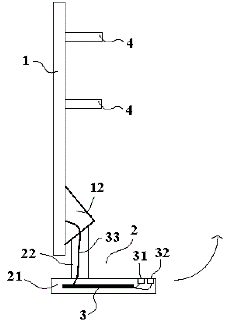
图2为本实用新型实施例的平板显示装置的结构示意图;2 is a schematic structural view of a flat panel display device according to an embodiment of the present invention;
图3为本实用新型实施例的平板显示装置被吊挂起来时的结构示意图。FIG. 3 is a schematic diagram of the structure of the flat panel display device according to the embodiment of the present invention when it is suspended.
其中附图标记为:1、显示屏;11、连接部;12、连接部;2、支撑座;21、底座;22、支撑架;3、驱动电路板;31、电源接口;32、视频信号接口;33、导线;4、吊挂结构;9、固定物;91、固定结构。The reference signs are: 1. display screen; 11. connection part; 12. connection part; 2. support base; 21. base; 22. support frame; 3. drive circuit board; 31. power interface; 32. video signal Interface; 33, wire; 4, hanging structure; 9, fixed object; 91, fixed structure.
具体实施方式Detailed ways
下面将结合本实用新型实施例中的附图,对本实用新型实施例的技术方案进行清楚、完整地描述,显然,所描述的实施例仅仅是本实用新型的一部分实施例,而不是全部的实施例。基于本实用新型中的实施例,本领域普通技术人员在没有做出创造性劳动的前提下所获得的所有其它实施例,都属于本实用新型保护的范围。The following will clearly and completely describe the technical solutions of the embodiments of the present invention in conjunction with the accompanying drawings in the embodiments of the present invention. Obviously, the described embodiments are only part of the embodiments of the present invention, rather than all of them. example. Based on the embodiments of the present utility model, all other embodiments obtained by persons of ordinary skill in the art without making creative efforts belong to the scope of protection of the present utility model.
本实用新型实施例提供一种平板显示装置,其包括显示屏以及与所述显示屏相连的支撑座,所述支撑座设有用于驱动所述显示屏进行显示的驱动电路板。An embodiment of the present invention provides a flat panel display device, which includes a display screen and a support seat connected to the display screen, and the support seat is provided with a driving circuit board for driving the display screen to display.
由于本实用新型的实施例的平板显示装置中,驱动电路板位于显示屏外,不占据显示屏内部的空间,显示屏内部也不用设计驱动电路板支架等结构,因此其显示屏的厚度可以很薄,易于实现薄型化,更加美观;而且,由于驱动电路板是设在支撑座中的,故平板显示装置中不必为了容纳驱动电路板而增设其它的器件,从而使平板显示装置的整体结构简单;同时,由于驱动电路板和显示屏是分开的,故对它们进行的维修操作比较方便,且二者产生的热可分别散出,故使平板显示装置的散热效果更好。Because in the flat panel display device of the embodiment of the present invention, the driving circuit board is located outside the display screen, does not occupy the space inside the display screen, and there is no need to design structures such as driving circuit board brackets inside the display screen, so the thickness of the display screen can be very large. Thin, easy to achieve thinning, more beautiful; moreover, because the driving circuit board is set in the support seat, so there is no need to add other devices to accommodate the driving circuit board in the flat panel display device, so that the overall structure of the flat panel display device is simple Simultaneously, since the drive circuit board and the display screen are separated, it is more convenient to maintain them, and the heat generated by the two can be dissipated separately, so the heat dissipation effect of the flat panel display device is better.
实施例Example
本实用新型实施例提供一种平板显示装置,其可为液晶电视、等离子电视、有机电致发光电视、表面传导电子发射电视、液晶显示器、等离子显示器、有机电致发光显示器、表面传导电子发射显示器等。The embodiment of the utility model provides a flat panel display device, which can be liquid crystal television, plasma television, organic electroluminescence television, surface conduction electron emission television, liquid crystal display, plasma display, organic electroluminescence display, surface conduction electron emission display wait.
如图2、图3所示,该平板显示装置包括显示屏1,以及与显示屏1相连的支撑座2。该支撑座2设有用于驱动显示屏1进行显示的的驱动电路板3。其中,显示屏1主要包括用于显示图像的光学系统(例如液晶显示装置的显示屏1可包括背光源、液晶显示面板、外壳等);驱动电路板3又称系统电路板,其中可包括电源电路板和控制电路板,驱动电路板3主要用于向显示屏1提供电能及视频驱动信号等,从而控制显示屏1显示预定的图像;支撑座2则可用于支撑显示屏1。As shown in FIG. 2 and FIG. 3 , the flat panel display device includes a
显然,由于本实施例的平板显示装置中,驱动电路板3位于支撑座2中,不占据显示屏1内部的空间,因此显示屏1的厚度可很薄,易于实现薄型化;且由于支撑座2是平板显示装置的原有部件,故将驱动电路板3设在其中不会增加平板显示装置的复杂性;同时,由于驱动电路板3和显示屏1是分开的,故其一方面方便维修,且还可达到更好的散热效果。Obviously, in the flat panel display device of this embodiment, the
优选地,支撑座2上还设有与驱动电路板3电连接的电源接口31和/或视频信号接口32,以为驱动电路板3提供所需的电能和视频信号,而驱动电路板3则可在对电能和视频信号进行预订处理后再将其提供给显示屏1。由于电能和视频信号需要先接入驱动电路板3后才能被提供给显示屏1,因此将电源接口31、视频信号接口32设在支撑座2上可以减短连接线的长度,使平板显示装置的结构更简单。Preferably, the
优选地,驱动电路板3可通过导线31与显示屏1电连接,该导线31可位于支撑座2内部,从而使平板显示装置的外观更加简洁。显然,驱动电路板3与显示屏1间的电连接也可通过其它方式实现,例如通过印在支撑座2内壁面上的金属线路实现;或者,驱动电路板3也可通过无线方式向显示屏1提供电能和视频驱动信号。Preferably, the
优选地,支撑座2可由底座21和支撑架22组成,驱动电路板3即位于底座21的中。其中,底座21用于与地面等支撑面相接触,从而为显示屏1提供稳固的支撑基础;而支撑架22则连接在底座21与显示屏1之间,从而支撑起显示屏1。为了保证支撑的稳定,底座21需要具有较大的面积,故将驱动电路板3设在底座21内正好可以充分利用其中的空间。显然,上述底座21和支撑架22还可进行许多公知的变化,例如:支撑架22可相对底座21进行转动,从而使显示屏1能呈现不同的角度;或者,支撑架22可为能伸缩的,从而调整显示屏1的高度。Preferably, the
优选地,支撑座2(或者说支撑架22)可通过连接部12与显示屏1相连,该连接部12可设在显示屏1远离显示面的一侧(即显示屏1的背侧),且连接部12内还设有扬声器(图中未示出)。这种设计充分利用了连接部12内部的空间,可在不增大平板显示装置体积的情况下使之具有发声的功能(例如可作为电视)。当然,支撑座2也可通过其它方式与显示屏1相连,例如直接连接在显示屏1的底部。Preferably, the support base 2 (or the support frame 22) can be connected to the
优选地,显示屏1和/或支撑座2上还可设有吊挂结构4,以将平板显示装置挂在墙壁、屋顶、家具等固定物9上,从而实现壁挂式显示。Preferably, the
其中,吊挂结构4优选为挂钩、挂环、挂绳、挂接凹槽、挂接凸起中的一种或多种,它们可与设在固定物9上的固定结构91(例如挂钉、挂环、挂接棒、凹槽、凸起等)相配合,从而将平板显示装置吊挂起来。显然,现有技术中已知的吊挂结构4的种类是十分多样的,故在此不再对其具体结构进行详细描述。Wherein, the hanging structure 4 is preferably one or more of a hook, a hanging ring, a lanyard, a hooking groove, and a hooking protrusion, and they can be connected with a fixed structure 91 (such as a peg) on the fixture 9. , hanging rings, hooking rods, grooves, protrusions, etc.) to hang the flat panel display device. Apparently, there are various types of hanging structures 4 known in the prior art, so no detailed description of their specific structures will be given here.
其中,吊挂结构4优选位于显示屏1远离显示面的一侧(即显示屏1的背侧),这样一方面可方便吊挂结构4的设计,另一方面可使吊挂结构4被显示屏1挡住而不对平板显示装置的外观产生影响。但应当理解的是,吊挂结构4也可设在显示屏1的其它任意位置处(如设在显示屏1顶面上),或者也可设在支撑座2上(例如图3中底座21的底面上即可设有能与固定物9配合的吊挂结构),或者显示屏1和支撑座2上也可同时具有吊挂结构4。Among them, the hanging structure 4 is preferably located on the side of the
优选地,支撑座2与显示屏1间转动连接(即支撑座2可相对于显示屏1进行转动),例如,如图2、图3所示,支撑架22连接在连接部12上,并能沿箭头方向转动。由于支撑座2与显示屏1间转动连接,故在用支撑座2支撑显示屏1时,显示屏1的角度可以调整以达到最佳的视觉效果;而在用吊挂结构4将显示屏1挂起时,如图3所示,支撑座2又可转到显示屏1后边位置,以免影响平板显示装置的外观(同时还可起到辅助定位的作用);当然,当显示屏1挂起时,支撑座2也可转到显示屏1前方、侧面等其它位置,从而起到不同的作用(例如可作为放置遥控器等物品的平台)。Preferably, the
优选地,平板显示装置中还包括用于将支撑座2与显示屏1相对定位的定位结构(图中未示出),从而在使用支撑座2支撑显示屏1时其可避免显示屏1晃动,而在使用吊挂结构4将平板显示装置挂起时,又可防止支撑座2从显示屏1后边掉下来。Preferably, the flat panel display device also includes a positioning structure (not shown) for positioning the
显然,上述转动连接和定位结构的形式是多样的,例如,支撑架22的端部可设有转动轴,而连接部12中可设有轴承,从而支撑架22可在连接部12中转动,或者,定位结构可为能在特定位置卡住支撑座2的卡块。由于现有技术中,转动连接和定位结构的种类是十分多样,故在此不再对它们的具体结构进行详细描述。Obviously, the forms of the above-mentioned rotating connection and positioning structure are varied, for example, the end of the
以上所述,仅为本实用新型的具体实施方式,但本实用新型的保护范围并不局限于此,任何熟悉本技术领域的技术人员在本实用新型揭露的技术范围内,可轻易想到的变化或替换,都应涵盖在本实用新型的保护范围之内。因此,本实用新型的保护范围应以所述权利要求的保护范围为准。The above is only a specific embodiment of the present utility model, but the scope of protection of the present utility model is not limited thereto. Any skilled person familiar with the technical field can easily think of changes within the technical scope disclosed by the utility model Or replacement, all should be covered within the scope of protection of the present utility model. Therefore, the protection scope of the present utility model should be based on the protection scope of the claims.
Claims (10)
Priority Applications (5)
| Application Number | Priority Date | Filing Date | Title |
|---|---|---|---|
| CN2011200754886U CN201956006U (en) | 2011-03-21 | 2011-03-21 | Flat-plate display device |
| US13/339,531 US20120243188A1 (en) | 2011-03-21 | 2011-12-29 | Flat display device |
| KR1020110145675A KR20120107424A (en) | 2011-03-21 | 2011-12-29 | Supporting seat and flat display device including the same |
| JP2012037225A JP2012198515A (en) | 2011-03-21 | 2012-02-23 | Flat-panel display |
| EP12160263A EP2503211A3 (en) | 2011-03-21 | 2012-03-20 | Flat display device |
Applications Claiming Priority (1)
| Application Number | Priority Date | Filing Date | Title |
|---|---|---|---|
| CN2011200754886U CN201956006U (en) | 2011-03-21 | 2011-03-21 | Flat-plate display device |
Publications (1)
| Publication Number | Publication Date |
|---|---|
| CN201956006U true CN201956006U (en) | 2011-08-31 |
Family
ID=44500110
Family Applications (1)
| Application Number | Title | Priority Date | Filing Date |
|---|---|---|---|
| CN2011200754886U Expired - Lifetime CN201956006U (en) | 2011-03-21 | 2011-03-21 | Flat-plate display device |
Country Status (5)
| Country | Link |
|---|---|
| US (1) | US20120243188A1 (en) |
| EP (1) | EP2503211A3 (en) |
| JP (1) | JP2012198515A (en) |
| KR (1) | KR20120107424A (en) |
| CN (1) | CN201956006U (en) |
Cited By (8)
| Publication number | Priority date | Publication date | Assignee | Title |
|---|---|---|---|---|
| CN102566103A (en) * | 2012-02-29 | 2012-07-11 | 深圳市华星光电技术有限公司 | Liquid crystal display device |
| CN102591045A (en) * | 2012-02-29 | 2012-07-18 | 深圳市华星光电技术有限公司 | Liquid crystal displayer and liquid crystal display device thereof |
| CN103968210A (en) * | 2014-04-29 | 2014-08-06 | 京东方科技集团股份有限公司 | Base of panel display device and panel display device |
| CN106657845A (en) * | 2016-10-24 | 2017-05-10 | 合肥惠科金扬科技有限公司 | Liquid crystal television |
| CN108622796A (en) * | 2018-07-26 | 2018-10-09 | 上海外高桥造船有限公司 | Lift support device and the modularization accommodation with it |
| CN108919887A (en) * | 2018-06-19 | 2018-11-30 | 芜湖华特电子科技有限公司 | A kind of outdoor industrial panel computer with dust reduction capability |
| CN108958390A (en) * | 2018-06-11 | 2018-12-07 | 芜湖华特电子科技有限公司 | A kind of industrial embedded computer convenient for equipment interconnection |
| CN109891480A (en) * | 2016-12-27 | 2019-06-14 | 索尼公司 | Display device |
Families Citing this family (5)
| Publication number | Priority date | Publication date | Assignee | Title |
|---|---|---|---|---|
| KR20160016763A (en) | 2013-03-15 | 2016-02-15 | 비데리 인코포레이티드 | Display device for displaying digital imaging |
| KR20160123616A (en) * | 2015-04-16 | 2016-10-26 | 삼성전자주식회사 | Display apparatus |
| JP6623129B2 (en) * | 2016-08-04 | 2019-12-18 | 富士通フロンテック株式会社 | Information display board |
| CN109151364B (en) * | 2018-09-12 | 2020-11-03 | 乐歌人体工学科技股份有限公司 | Heightening table |
| KR102521485B1 (en) | 2018-09-21 | 2023-04-14 | 삼성전자주식회사 | Display apparatus |
Family Cites Families (13)
| Publication number | Priority date | Publication date | Assignee | Title |
|---|---|---|---|---|
| JP2001042779A (en) * | 1999-07-29 | 2001-02-16 | Toshiba Corp | Personal computer |
| JP4094937B2 (en) * | 2001-11-19 | 2008-06-04 | 三星電子株式会社 | Monitor device |
| US7061754B2 (en) * | 2002-06-13 | 2006-06-13 | Gerald Moscovitch | LCD system having integrated CPU |
| EP1420327A1 (en) * | 2002-11-14 | 2004-05-19 | Hewlett-Packard Company (a Delaware corporation) | Support |
| EP1619438B1 (en) * | 2004-07-21 | 2010-03-31 | LG Electronics Inc. | Wall mounting structure for a flat panel display |
| KR100777078B1 (en) * | 2006-07-27 | 2007-11-16 | 주식회사 대우일렉트로닉스 | Stand and Wall Mount Rotation Control |
| JP2008292691A (en) * | 2007-05-23 | 2008-12-04 | Sony Corp | Display device |
| US7813118B2 (en) * | 2008-04-14 | 2010-10-12 | Bose Corporation | Device bracket with integrated device hub |
| US7883069B2 (en) * | 2008-05-08 | 2011-02-08 | Samsung Electronics Co. Ltd | Lifting device of a display apparatus |
| US20100321865A1 (en) * | 2009-06-19 | 2010-12-23 | Ching-Chuan Huang | Electronic Apparatus with Embedded Power Supply Device |
| US8172186B2 (en) * | 2009-07-17 | 2012-05-08 | Aopen Incorporated | Display support seat |
| TWM384508U (en) * | 2010-01-15 | 2010-07-11 | Aopen Inc | Vapor chamber device with metal mesh heat-dissipating structure |
| TWI433540B (en) * | 2010-09-09 | 2014-04-01 | Wistron Corp | Panel fixing mechanism and display device thereof |
-
2011
- 2011-03-21 CN CN2011200754886U patent/CN201956006U/en not_active Expired - Lifetime
- 2011-12-29 US US13/339,531 patent/US20120243188A1/en not_active Abandoned
- 2011-12-29 KR KR1020110145675A patent/KR20120107424A/en not_active Ceased
-
2012
- 2012-02-23 JP JP2012037225A patent/JP2012198515A/en active Pending
- 2012-03-20 EP EP12160263A patent/EP2503211A3/en not_active Withdrawn
Cited By (13)
| Publication number | Priority date | Publication date | Assignee | Title |
|---|---|---|---|---|
| CN102566103A (en) * | 2012-02-29 | 2012-07-11 | 深圳市华星光电技术有限公司 | Liquid crystal display device |
| CN102591045A (en) * | 2012-02-29 | 2012-07-18 | 深圳市华星光电技术有限公司 | Liquid crystal displayer and liquid crystal display device thereof |
| WO2013127081A1 (en) * | 2012-02-29 | 2013-09-06 | 深圳市华星光电技术有限公司 | Liquid crystal display device |
| CN102566103B (en) * | 2012-02-29 | 2015-05-20 | 深圳市华星光电技术有限公司 | Liquid crystal display device |
| CN103968210A (en) * | 2014-04-29 | 2014-08-06 | 京东方科技集团股份有限公司 | Base of panel display device and panel display device |
| CN103968210B (en) * | 2014-04-29 | 2016-01-20 | 京东方科技集团股份有限公司 | The base of panel display apparatus and panel display apparatus |
| CN106657845A (en) * | 2016-10-24 | 2017-05-10 | 合肥惠科金扬科技有限公司 | Liquid crystal television |
| CN109891480A (en) * | 2016-12-27 | 2019-06-14 | 索尼公司 | Display device |
| US10989352B2 (en) | 2016-12-27 | 2021-04-27 | Sony Corporation | Display apparatus |
| CN108958390A (en) * | 2018-06-11 | 2018-12-07 | 芜湖华特电子科技有限公司 | A kind of industrial embedded computer convenient for equipment interconnection |
| CN108919887A (en) * | 2018-06-19 | 2018-11-30 | 芜湖华特电子科技有限公司 | A kind of outdoor industrial panel computer with dust reduction capability |
| CN108622796A (en) * | 2018-07-26 | 2018-10-09 | 上海外高桥造船有限公司 | Lift support device and the modularization accommodation with it |
| CN108622796B (en) * | 2018-07-26 | 2024-05-07 | 上海外高桥造船有限公司 | Hoisting supporting device and modularized living cabin with same |
Also Published As
| Publication number | Publication date |
|---|---|
| US20120243188A1 (en) | 2012-09-27 |
| JP2012198515A (en) | 2012-10-18 |
| KR20120107424A (en) | 2012-10-02 |
| EP2503211A3 (en) | 2012-10-10 |
| EP2503211A2 (en) | 2012-09-26 |
Similar Documents
| Publication | Publication Date | Title |
|---|---|---|
| JP2012198515A (en) | Flat-panel display | |
| CN104633420B (en) | Display device suspension holdfast | |
| CN201227010Y (en) | Rotary TV cabinet | |
| CN218032286U (en) | A Splicing Large Screen Control System | |
| CN214744541U (en) | Display support | |
| CN212012922U (en) | A live video interactive display device | |
| CN204740751U (en) | Folding multi-interface output physical booth with display touch function | |
| CN210691864U (en) | Multifunctional media wall | |
| CN209928874U (en) | An outdoor LED display adjustable bracket | |
| CN206102231U (en) | Take embroidery show shelf of auto -induction lamp | |
| CN209762627U (en) | Projector support | |
| CN101494013A (en) | Hanging display | |
| CN209846686U (en) | Work of fine arts show shelf | |
| CN201119204Y (en) | Electric control rotating base and plane display frame of electric control rotating base | |
| CN201170426Y (en) | A flat-panel TV base supporting device | |
| CN208273014U (en) | Augmented reality terminal and its plateform system | |
| CN220186355U (en) | A digital media art advertising and promotion device | |
| CN206379136U (en) | A kind of digital photo frame | |
| CN207979421U (en) | A silver mirror bracket with terminal adjustment | |
| CN224096365U (en) | A transparent spherical display device with an embedded holographic fan | |
| CN206671749U (en) | A kind of star space projection device and starry sky observation ward | |
| CN218409322U (en) | An environmental art design displays screens from multiple angles | |
| CN209574119U (en) | A kind of architectural design showing stand | |
| CN202972431U (en) | display device | |
| CN210424348U (en) | Integrated display equipment with lighting and displaying functions |
Legal Events
| Date | Code | Title | Description |
|---|---|---|---|
| C14 | Grant of patent or utility model | ||
| GR01 | Patent grant | ||
| CX01 | Expiry of patent term |
Granted publication date: 20110831 |
|
| CX01 | Expiry of patent term |