EP3833477B1 - Container for treating a fluid with an ion-exchange system and corresponding ion chromatography method - Google Patents
Container for treating a fluid with an ion-exchange system and corresponding ion chromatography method Download PDFInfo
- Publication number
- EP3833477B1 EP3833477B1 EP19745746.8A EP19745746A EP3833477B1 EP 3833477 B1 EP3833477 B1 EP 3833477B1 EP 19745746 A EP19745746 A EP 19745746A EP 3833477 B1 EP3833477 B1 EP 3833477B1
- Authority
- EP
- European Patent Office
- Prior art keywords
- container
- fluid
- particles
- chamber
- diffusers
- Prior art date
- Legal status (The legal status is an assumption and is not a legal conclusion. Google has not performed a legal analysis and makes no representation as to the accuracy of the status listed.)
- Active
Links
Images


Classifications
-
- G—PHYSICS
- G01—MEASURING; TESTING
- G01N—INVESTIGATING OR ANALYSING MATERIALS BY DETERMINING THEIR CHEMICAL OR PHYSICAL PROPERTIES
- G01N30/00—Investigating or analysing materials by separation into components using adsorption, absorption or similar phenomena or using ion-exchange, e.g. chromatography or field flow fractionation
- G01N30/02—Column chromatography
- G01N30/60—Construction of the column
- G01N30/6004—Construction of the column end pieces
- G01N30/6017—Fluid distributors
-
- B—PERFORMING OPERATIONS; TRANSPORTING
- B01—PHYSICAL OR CHEMICAL PROCESSES OR APPARATUS IN GENERAL
- B01D—SEPARATION
- B01D15/00—Separating processes involving the treatment of liquids with solid sorbents; Apparatus therefor
- B01D15/08—Selective adsorption, e.g. chromatography
- B01D15/10—Selective adsorption, e.g. chromatography characterised by constructional or operational features
- B01D15/22—Selective adsorption, e.g. chromatography characterised by constructional or operational features relating to the construction of the column
-
- B—PERFORMING OPERATIONS; TRANSPORTING
- B01—PHYSICAL OR CHEMICAL PROCESSES OR APPARATUS IN GENERAL
- B01D—SEPARATION
- B01D15/00—Separating processes involving the treatment of liquids with solid sorbents; Apparatus therefor
- B01D15/08—Selective adsorption, e.g. chromatography
- B01D15/26—Selective adsorption, e.g. chromatography characterised by the separation mechanism
- B01D15/36—Selective adsorption, e.g. chromatography characterised by the separation mechanism involving ionic interaction, e.g. ion-exchange, ion-pair, ion-suppression or ion-exclusion
- B01D15/361—Ion-exchange
- B01D15/363—Anion-exchange
-
- B—PERFORMING OPERATIONS; TRANSPORTING
- B01—PHYSICAL OR CHEMICAL PROCESSES OR APPARATUS IN GENERAL
- B01J—CHEMICAL OR PHYSICAL PROCESSES, e.g. CATALYSIS OR COLLOID CHEMISTRY; THEIR RELEVANT APPARATUS
- B01J41/00—Anion exchange; Use of material as anion exchangers; Treatment of material for improving the anion exchange properties
- B01J41/04—Processes using organic exchangers
- B01J41/07—Processes using organic exchangers in the weakly basic form
-
- B—PERFORMING OPERATIONS; TRANSPORTING
- B01—PHYSICAL OR CHEMICAL PROCESSES OR APPARATUS IN GENERAL
- B01J—CHEMICAL OR PHYSICAL PROCESSES, e.g. CATALYSIS OR COLLOID CHEMISTRY; THEIR RELEVANT APPARATUS
- B01J41/00—Anion exchange; Use of material as anion exchangers; Treatment of material for improving the anion exchange properties
- B01J41/08—Use of material as anion exchangers; Treatment of material for improving the anion exchange properties
- B01J41/12—Macromolecular compounds
- B01J41/13—Macromolecular compounds obtained otherwise than by reactions only involving unsaturated carbon-to-carbon bonds
-
- B—PERFORMING OPERATIONS; TRANSPORTING
- B01—PHYSICAL OR CHEMICAL PROCESSES OR APPARATUS IN GENERAL
- B01J—CHEMICAL OR PHYSICAL PROCESSES, e.g. CATALYSIS OR COLLOID CHEMISTRY; THEIR RELEVANT APPARATUS
- B01J47/00—Ion-exchange processes in general; Apparatus therefor
- B01J47/02—Column or bed processes
- B01J47/022—Column or bed processes characterised by the construction of the column or container
-
- B—PERFORMING OPERATIONS; TRANSPORTING
- B01—PHYSICAL OR CHEMICAL PROCESSES OR APPARATUS IN GENERAL
- B01J—CHEMICAL OR PHYSICAL PROCESSES, e.g. CATALYSIS OR COLLOID CHEMISTRY; THEIR RELEVANT APPARATUS
- B01J47/00—Ion-exchange processes in general; Apparatus therefor
- B01J47/02—Column or bed processes
- B01J47/04—Mixed-bed processes
-
- B—PERFORMING OPERATIONS; TRANSPORTING
- B01—PHYSICAL OR CHEMICAL PROCESSES OR APPARATUS IN GENERAL
- B01J—CHEMICAL OR PHYSICAL PROCESSES, e.g. CATALYSIS OR COLLOID CHEMISTRY; THEIR RELEVANT APPARATUS
- B01J47/00—Ion-exchange processes in general; Apparatus therefor
- B01J47/10—Ion-exchange processes in general; Apparatus therefor with moving ion-exchange material; with ion-exchange material in suspension or in fluidised-bed form
-
- G—PHYSICS
- G01—MEASURING; TESTING
- G01N—INVESTIGATING OR ANALYSING MATERIALS BY DETERMINING THEIR CHEMICAL OR PHYSICAL PROPERTIES
- G01N30/00—Investigating or analysing materials by separation into components using adsorption, absorption or similar phenomena or using ion-exchange, e.g. chromatography or field flow fractionation
- G01N30/02—Column chromatography
- G01N30/60—Construction of the column
- G01N30/6052—Construction of the column body
- G01N30/6069—Construction of the column body with compartments or bed substructure
-
- G—PHYSICS
- G01—MEASURING; TESTING
- G01N—INVESTIGATING OR ANALYSING MATERIALS BY DETERMINING THEIR CHEMICAL OR PHYSICAL PROPERTIES
- G01N30/00—Investigating or analysing materials by separation into components using adsorption, absorption or similar phenomena or using ion-exchange, e.g. chromatography or field flow fractionation
- G01N30/96—Investigating or analysing materials by separation into components using adsorption, absorption or similar phenomena or using ion-exchange, e.g. chromatography or field flow fractionation using ion-exchange
Definitions
- the application relates generally to ion chromatography and, more particularly, to an ion-exchange system and method thereof.
- Ion exchanger systems such as those employed in ion chromatography, can be used to remove or separate molecules from a fluid.
- the fluid may pass upwardly through a bed of ion-exchange resin contained in a container of the ion exchanger system to remove the molecules from the fluid.
- the ion exchanger system typically has an inlet at the bottom to receive the fluid into the container and an outlet at the top to remove the fluid from the container.
- the fluid can be pressurized and injected into the container.
- the amount of molecules removed from the fluid may depend on the time that the fluid is in contact with the bed of ion-exchange resin. However, a portion of the fluid may pass through the resin at a rate different from rates of other portions of the fluid passing through the resin.
- US 3 802 568 A discloses a device or apparatus for continuously treating fluids in an ion exchange bed.
- the device or apparatus comprises a lid, a hollow body, a bottom, an upper intermediate plate, and a lower intermediate plate.
- a container for treating a fluid with an ion-exchange system comprising a housing extending in an upright position along a longitudinal axis between a bottom port and an opposed top port, the housing having an internal chamber defined therein; a bottom plate disposed in the internal chamber perpendicular to the longitudinal axis at a predetermined height above the bottom port and having a plurality of openings defined therethrough, the bottom plate dividing the internal chamber between a main chamber and a bottom chamber, the bottom chamber defined between the bottom plate and the bottom port; and a plurality of diffusers in fluid flow communication with the bottom chamber extending from the bottom plate into the main chamber, each one of the plurality of diffusers being received in a respective one of the plurality of openings of the bottom plate and having a diffuser tube section projecting upwardly from the bottom plate and being in fluid flow communication with the bottom chamber, the diffuser tube section having radial openings circumferentially distributed along a length thereof to
- an ion chromatography method for treating a fluid with ion-exchange treatment particles disposed in a container comprising uniformly distributing the fluid in a bed of silex particles of the treatment particles through a plurality of bottom diffusers; raising the fluid from the bed of silex particles into, and through, a bed of ion-exchange particles of the treatment particles; and evacuating the fluid from the container.
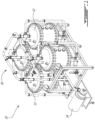
- Fig. 1 illustrates an ion-exchange system 10 that may be used in ion chromatography.
- the ion-exchange system 10 may be used for treating a fluid to remove ions, particles, and/or molecules from the fluid.
- the ion-exchange system may be used in the food and beverage industry as part of a purification and separation system.
- the ion-exchange system 10 may be used in juice debittering, juice clarification, and the like. It is understood that other suitable applications outside the beverage industry for removing ions, particles and/or molecules from the fluid using the ion-exchange system 10 are also contemplated.
- the ion-exchange system 10 includes four containers 12.
- the container 12 is intended to refer to a vessel, receptacle, tank, and the like.
- the container 12 may receive and treat the fluid with treatment particles that may be disposed therein.
- the treatment particles may contain a bed of ion-exchange particles or resin to treat the fluid.
- the ion-exchange particles are intended to refer to resins, beads, or the like, that can separate ions and/or molecules from the fluid.
- the ion-exchange resin may be selected to provide the desired separation and removal of the ions and/or molecules from the fluid.
- the ion-exchange particles or resin to treat the fluid is preferably a weak anion exchange resin such as a resin of the acrylic or styrene type.
- weak anion exchange resin is comprising ternary amines that are neutral at a pH greater than 10 and ionized at a pH lower than 10 and may therefore be useful for capturing chemical species (such as weak acids, in particular organic acids).
- the resin is an acrylic-type anion exchange resin having a capacity between 1.6-3.2.
- the container 12 may include any suitable material for containing the fluid and the treatment particles.
- the ion-exchange system may include a pump 14 to pressurize the fluid and a piping network 16 to carry the fluid into and out of the containers 12.
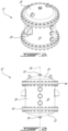
- Figs. 2A-2C illustrates the container 12.
- the container 12 has a housing 20 to receive the treatment particles, a bottom cover 22, an opposed top cover 24, and diffusers 26 positioned inside the container 12 to distribute the fluid in the housing 20.
- the fluid may be uniformly distributed across the housing 20 through the diffusers 26.
- relative terms such as, “top”, “bottom”, “side”, “horizontal”, “vertical”, “upright”, “above”, and the like are used herein to describe one element's relationship to another element as illustrated in the figures. It is understood that these relative terms are intended to encompass different orientations of the elements in addition to the orientation depicted in the figures.
- the housing 20 may extend in an upright position along a longitudinal axis 28 ( Fig. 2B ) between a bottom port 30 defined in the bottom cover 22 and an opposed top port 32 defined in the top cover 24.
- the bottom port 30 and the top port 32 may be openings.
- the fluid may be introduced in the container 12 from the bottom port 30 and/or the top port 32 and evacuated from the bottom port 30 and/or the top port 32, and vice versa.
- a fluid source (not shown) may provide the fluid to the container 12.
- the fluid may be pressurized and injected into the container 12.
- the pump 14 may pressurize the fluid.
- a vacuum pump may be connected to the top port 32 to evacuate the fluid from the container 12.
- the housing 20 may have a sidewall 34 extending around the longitudinal axis 28 from the bottom cover 22 to the top cover 24.
- the housing 20 may have a cylindrical shape. In some embodiments, the housing 20 may have an oval shape.
- the container 12 has an internal chamber defined therein.
- the internal chamber may be divided into sub-chambers.
- the container 12 may have a main chamber 36, a bottom chamber 38, and a top chamber 40.
- the main chamber 36 is disposed between the bottom chamber 38 and the top chamber 40.
- the main chamber 36 is defined in the housing 20 such that the sidewall 34 at least partially delimits the main chamber 36.
- the main chamber 36 is adapted to contain therein the treatment particles.
- the bottom chamber 38 is defined between the main chamber 36 and the bottom cover 22, and the top chamber 40 is defined between the main chamber 36 and the top cover 24.
- the bottom chamber 38 is free from the treatment particles.
- the top chamber 40 may be free from the treatment particles.
- the container 12 includes a bottom plate 42 disposed therein at a predetermined height above the bottom port 30 such that the bottom chamber 38 may be defined between the bottom plate 42 and the bottom port 30.
- the bottom plate 42 may be disposed perpendicular to the longitudinal axis 28.
- the bottom plate 42 delimits a bottom portion of the main chamber 36.
- the bottom plate 42 may extend across the sidewall 34 of the housing 20. In other words, a periphery of the bottom plate 42 may be in contact with the sidewall 34.
- the bottom plate 42 may form a common divider between the main chamber 36 and the bottom chamber 38.
- the container 12 may include a top plate 44 disposed therein at a predetermined depth below the top port 32 such that the top chamber 40 may be defined between the top plate 44 and the top port 32.
- the top plate 44 may be disposed perpendicular to the longitudinal axis 28.
- the top plate 44 delimits a top portion of the main chamber 36.
- the top plate 44 may extend across the sidewall 34 of the housing 20. In other words, a periphery of the top plate 44 may be in contact with the sidewall 34.
- the top plate 44 may form a common divider between the main chamber 36 and the top chamber 40.
- the diffusers 26 may include bottom diffusers 26A that extend from the bottom plate 42 into the main chamber 36.
- each diffuser 26 has a diffuser tube section 46 that projects upwardly from the bottom plate 42 into the main chamber 36.
- a predetermined height of the diffuser tube section 46 may be determined relative to the size and shape of the container 12. The predetermined height of the diffuser tube section 46 may depend on the selection of the treatment particles.
- the treatment particles may include the bed of ion-exchange particles disposed above a bed of silex particles.
- the silex particles are intended to refer to any suitable forms of quartz, flint, stones, or any of the other forms of silica and/or silicate, and the like.
- the height of the diffuser tube section 46 may extend only within the bed of silex particles. In some embodiments, the diffuser tube section 46 may not extend in the bed of ion-exchange particles.
- the bottom diffusers 26A may be uniformly distributed over the bottom plate 42.
- the bottom diffusers 26A are in fluid flow communication with the bottom chamber 38.
- the fluid may be injected into the bottom chamber 38 through the bottom port 30.
- the fluid may flow into the diffusers 26 to be radially discharged in the main chamber 36.
- the container 12 may include top diffusers 26B that extend from the top plate 44 into the main chamber 36.
- each diffuser has a diffuser tube section 46 that projects downwardly from the top plate 44 into the main chamber 36.
- a predetermined depth of the diffuser tube section 46 may be determined relative to the size and shape of the container 12. The predetermined depth of the diffuser tube section 46 may depend on the selection of the treatment particles.
- the treatment particles may include the bed of silex particles disposed above the bed of ion-exchange particles.
- the depth of the diffuser tube section 46 may extend only in the bed of silex particles.
- the diffuser tube section 46 of the top diffusers 26B may not extend in the bed of ion-exchange particles.
- the top diffusers 26B may be uniformly distributed over the top plate 44.
- top cover 24 is shown.
- the top port 32 is positioned in a center of the top cover 24. It is understood that other configurations of the top port 32 may be employed.
- the bottom cover 22 may be similar to the top cover 24.
- the bottom plate 42 is shown.
- the bottom plate 42 is perforated and includes openings 48 defined therethrough.
- Each opening 48 may receive a corresponding diffuser 26.
- the corresponding diffuser 26 may extend through the bottom plate 42 through a respective opening 48.
- each one of the openings 48 of the bottom plate 42 is in fluid flow communication with a corresponding diffuser tube section 46. That is, two or more openings 48 may be in fluid flow communication with the same diffuser tube section 46.
- the diffuser 26AA expands over four openings 48.
- the diffuser 26A expands over one opening 48.
- the bottom plate 42 may have a circular shape. In other embodiments, the bottom plate 42 may have a different shape, such as oval, and the like.
- a density of the diffusers 26 may be defined by a number of the diffusers 26 per unit area of the bottom plate 42. In some embodiments, the density of the diffusers 26 is between a minimum value and a maximum value of diffusers 26 per meter square (number of diffusers/m 2 ). In some embodiments, the density is between 50 and 70 diffusers/m 2 . In some embodiments, the density is between 60 and 65 diffusers/m 2 . In some embodiments, the density is, or about, 62.5 diffusers/m 2 . The density of the diffusers may be 0.016 m 2 /diffuser tube.
- the area of the bottom plate 42 is 0.64 m 2 .
- 40 diffusers 26 may be used and uniformly distributed over the bottom plate 42.
- the diffuser tube section 46 has a root opening 50 at one end and a closed opposite end 52.
- the diffuser tube section 46 may be in fluid flow communication with the bottom chamber 38 through the root opening 50.
- the diffuser tube section 46 may have radial openings 54 circumferentially distributed along a length thereof between the bottom plate 42 and the closed end 52. A flow path of the fluid may be defined from the root opening 50 to the radial openings 54.
- the diffuser 26 may include the diffuser tube section 46 and a root tube section 56.
- the root tube section 56 is intended to refer to any suitable tube to reach the fluid within the bottom chamber 38.
- the root tube section 56 may project from the bottom plate 42 into the bottom chamber 38.
- the root tube section 56 may be in fluid flow communication with the bottom chamber 38 through another root opening 50A.
- the diffuser 26 may be sized to provide a pressure drop therethrough.
- the pressure drop may be between 1 and 3 bars for a flow of the fluid at a volumetric flow rate between 60 and 70 meter cube per hour (m 3 /h).
- the diffusers 26 may be sized and shaped to uniformly distribute the fluid in the bed of silex particles.
- the diffuser tube section 46 may have a diameter that is between 14 mm and 17 mm.
- the height of the diffuser tube section 46 may be about 50 mm. It is understood that other sizes of the diameter and the height may be used.
- a flowrate of the fluid per diffuser 26 may vary between 25 litres per hour (L/h) and 1 500 L/h.
- the pump 14 may vary the flowrate of the fluid flowing to the diffusers 26.
- the diffuser 26 may be made from a stainless steel, titanium alloy, or a combination of stainless steel and titanium alloy.
- the diffuser 26 may be made from a titanium loaded stainless steel.
- the material of the diffuser 26 may be known as "Alloy 316 Ti”.
- the radial openings 54 may have V-shaped openings.
- the V-shaped openings 54 may block the silex particles 58 from entering into the diffusers 26.
- the size of the silex particle 58 may be greater than the size of the radial opening 54.
- the housing 20 may have a height along the longitudinal axis 28 and a diameter extending in a plane perpendicular to the longitudinal axis 28.
- the shape of the housing 20 may be referred to as "super square".
- the term super square is intended to refer to a shape of the housing 20 where the values of the height and the diameter are equal, or are near each other.
- a ratio of the height over the diameter may be between 0.75 and 1.25.
- the ratio of the height over the diameter is between 0.8 and 1.2.
- the ratio of the height over the diameter is between 0.9 and 1.1.
- the ratio of the height over the diameter is, or about, 1.
- the treatment particles may be provided inside the main chamber 36 to a filling height that extends from the bottom plate 42 toward the top plate.
- the filling height may be between 50% and 100% of the total height of the housing 20.
- the treatment particles may expand in volume during the treatment of the fluid.
- the container 12 may be sold separately from the treatment particles.
- the container 12 may be sold with the bed of silex particles 58 and the bed of ion-exchange particles.
- the ion-exchange system 10 may include the container 12 with an identical bottom half and top half. That is, for example, the top plate 44 and top diffusers 26B mirror the bottom plate 42 and bottom diffusers 26A.
- a regenerating or washing fluid may be used to regenerate or wash the ion-exchange particles. For example, after treating the fluid, the ion-exchange particles may be washed to remove the molecules that were separated from the fluid, the molecules retained by the ion-exchange particles, or both.
- a method may be provided for treating the fluid.
- the method may include uniformly distributing the fluid in the bed of silex particles 58 in the container 12, raising the fluid from the bed of silex particles into, and through, the bed of ion-exchange particles, and evacuating or retrieving the fluid from the container 12.
- the method may include a reverse washing flow from the top port 32 to the bottom port 30 to wash and regenerate the ion-exchange particles.
- the fluid may flow through the container 12 from the bottom port 30, to the bottom chamber 38, to the main chamber 36, to the top chamber 40, and flow out of the container 12 through the top port 32.
- the fluid may enter the housing 20 through the bottom port 30.
- the fluid may flow into the bottom diffusers 26A.
- the bottom diffusers 26A may uniformly discharge the fluid in the bed of silex particles 58.
- the fluid may rise from the bed of silex particles 58 into the bed of ion-exchange particles 60.
- the fluid may flow into the top diffusers 26B.
- the fluid may exit the container through the top port 32.
- the fluid may flow through the container 12 from the top port 32, to the top chamber 40, to the main chamber 36, to the bottom chamber 38, and flow out of the container 12 through the bottom port 30.
- the fluid may enter the housing 20 through the top port 32.
- the fluid may flow into the top diffusers 26B.
- the top diffusers 26B may uniformly discharge the fluid in the bed of silex particles 58.
- the fluid may flow from the bed of silex particles 58 into the bed of ion-exchange particles 60.
- the fluid may flow into the bottom diffusers 26A.
- the fluid may exit the container through the bottom port 30.
- the bottom diffusers may be identical to the top diffusers.
- the bottom plate 42 may be identical to the top plate.
Landscapes
- Chemical & Material Sciences (AREA)
- Chemical Kinetics & Catalysis (AREA)
- Organic Chemistry (AREA)
- Analytical Chemistry (AREA)
- General Health & Medical Sciences (AREA)
- Biochemistry (AREA)
- Physics & Mathematics (AREA)
- General Physics & Mathematics (AREA)
- Immunology (AREA)
- Pathology (AREA)
- Life Sciences & Earth Sciences (AREA)
- Health & Medical Sciences (AREA)
- Devices And Processes Conducted In The Presence Of Fluids And Solid Particles (AREA)
- Treatment Of Water By Ion Exchange (AREA)
Description
- This application claims the benefit of
US 62/716,503 filed on August 9, 2018 - The application relates generally to ion chromatography and, more particularly, to an ion-exchange system and method thereof.
- Ion exchanger systems, such as those employed in ion chromatography, can be used to remove or separate molecules from a fluid. The fluid may pass upwardly through a bed of ion-exchange resin contained in a container of the ion exchanger system to remove the molecules from the fluid. The ion exchanger system typically has an inlet at the bottom to receive the fluid into the container and an outlet at the top to remove the fluid from the container. In operation, the fluid can be pressurized and injected into the container.
- The amount of molecules removed from the fluid may depend on the time that the fluid is in contact with the bed of ion-exchange resin. However, a portion of the fluid may pass through the resin at a rate different from rates of other portions of the fluid passing through the resin.
-
US 3 802 568 A discloses a device or apparatus for continuously treating fluids in an ion exchange bed. The device or apparatus comprises a lid, a hollow body, a bottom, an upper intermediate plate, and a lower intermediate plate. - In one aspect, which is defined in the independent apparatus claim 1, there is provided a container for treating a fluid with an ion-exchange system, the container comprising a housing extending in an upright position along a longitudinal axis between a bottom port and an opposed top port, the housing having an internal chamber defined therein; a bottom plate disposed in the internal chamber perpendicular to the longitudinal axis at a predetermined height above the bottom port and having a plurality of openings defined therethrough, the bottom plate dividing the internal chamber between a main chamber and a bottom chamber, the bottom chamber defined between the bottom plate and the bottom port; and a plurality of diffusers in fluid flow communication with the bottom chamber extending from the bottom plate into the main chamber, each one of the plurality of diffusers being received in a respective one of the plurality of openings of the bottom plate and having a diffuser tube section projecting upwardly from the bottom plate and being in fluid flow communication with the bottom chamber, the diffuser tube section having radial openings circumferentially distributed along a length thereof to radially discharge the fluid in the main chamber.
- In a further aspect, which is defined in the
method claim 16, there is provided an ion chromatography method for treating a fluid with ion-exchange treatment particles disposed in a container, the method comprising uniformly distributing the fluid in a bed of silex particles of the treatment particles through a plurality of bottom diffusers; raising the fluid from the bed of silex particles into, and through, a bed of ion-exchange particles of the treatment particles; and evacuating the fluid from the container. - Reference is now made to the accompanying figures in which:
-
Fig. 1 is a perspective view of an ion-exchange system including four containers; -
Fig. 2A is a perspective view of one of the containers shown inFig. 1 ; -
Fig. 2B is a front view of the container ofFig. 2A ; -
Fig. 2C is perspective cross-sectional view of the container, showing diffusers disposed inside the container; -
Fig. 3A is a perspective view of a top cover of the container; -
Fig. 3B is a cross-sectional view of the top cover; -
Fig. 4A is a perspective view of the bottom plate; -
Fig. 4B is a top view of the bottom plate; -
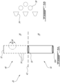
Fig. 5A is one of the diffusers ofFig. 2C ; -
Fig. 5B is an enlarged view of a portion of the diffuser; -
Fig. 6 is a housing of the container; and -
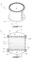
Fig. 7 is a cross-sectional view of the container. -
Fig. 1 illustrates an ion-exchange system 10 that may be used in ion chromatography. The ion-exchange system 10 may be used for treating a fluid to remove ions, particles, and/or molecules from the fluid. The ion-exchange system may be used in the food and beverage industry as part of a purification and separation system. For example, the ion-exchange system 10 may be used in juice debittering, juice clarification, and the like. It is understood that other suitable applications outside the beverage industry for removing ions, particles and/or molecules from the fluid using the ion-exchange system 10 are also contemplated. - In the embodiment shown in
Fig. 1 , the ion-exchange system 10 includes fourcontainers 12. Thecontainer 12 is intended to refer to a vessel, receptacle, tank, and the like. Thecontainer 12 may receive and treat the fluid with treatment particles that may be disposed therein. - The treatment particles may contain a bed of ion-exchange particles or resin to treat the fluid. The ion-exchange particles are intended to refer to resins, beads, or the like, that can separate ions and/or molecules from the fluid. The ion-exchange resin may be selected to provide the desired separation and removal of the ions and/or molecules from the fluid.
- The ion-exchange particles or resin to treat the fluid is preferably a weak anion exchange resin such as a resin of the acrylic or styrene type. Preferably, weak anion exchange resin is comprising ternary amines that are neutral at a pH greater than 10 and ionized at a pH lower than 10 and may therefore be useful for capturing chemical species (such as weak acids, in particular organic acids). Preferably, the resin is an acrylic-type anion exchange resin having a capacity between 1.6-3.2.
- The
container 12 may include any suitable material for containing the fluid and the treatment particles. The ion-exchange system may include apump 14 to pressurize the fluid and apiping network 16 to carry the fluid into and out of thecontainers 12. -
Figs. 2A-2C , illustrates thecontainer 12. Thecontainer 12 has ahousing 20 to receive the treatment particles, abottom cover 22, an opposedtop cover 24, anddiffusers 26 positioned inside thecontainer 12 to distribute the fluid in thehousing 20. The fluid may be uniformly distributed across thehousing 20 through thediffusers 26. It will be appreciated that relative terms such as, "top", "bottom", "side", "horizontal", "vertical", "upright", "above", and the like are used herein to describe one element's relationship to another element as illustrated in the figures. It is understood that these relative terms are intended to encompass different orientations of the elements in addition to the orientation depicted in the figures. - The
housing 20 may extend in an upright position along a longitudinal axis 28 (Fig. 2B ) between abottom port 30 defined in thebottom cover 22 and an opposedtop port 32 defined in thetop cover 24. Thebottom port 30 and thetop port 32 may be openings. For example, the fluid may be introduced in thecontainer 12 from thebottom port 30 and/or thetop port 32 and evacuated from thebottom port 30 and/or thetop port 32, and vice versa. A fluid source (not shown) may provide the fluid to thecontainer 12. The fluid may be pressurized and injected into thecontainer 12. Thepump 14 may pressurize the fluid. A vacuum pump may be connected to thetop port 32 to evacuate the fluid from thecontainer 12. - The
housing 20 may have asidewall 34 extending around thelongitudinal axis 28 from thebottom cover 22 to thetop cover 24. Thehousing 20 may have a cylindrical shape. In some embodiments, thehousing 20 may have an oval shape. - The
container 12 has an internal chamber defined therein. The internal chamber may be divided into sub-chambers. For example, thecontainer 12 may have amain chamber 36, abottom chamber 38, and atop chamber 40. Themain chamber 36 is disposed between thebottom chamber 38 and thetop chamber 40. Themain chamber 36 is defined in thehousing 20 such that thesidewall 34 at least partially delimits themain chamber 36. Themain chamber 36 is adapted to contain therein the treatment particles. Thebottom chamber 38 is defined between themain chamber 36 and thebottom cover 22, and thetop chamber 40 is defined between themain chamber 36 and thetop cover 24. In some embodiments, thebottom chamber 38 is free from the treatment particles. Similarly, thetop chamber 40 may be free from the treatment particles. - The
container 12 includes abottom plate 42 disposed therein at a predetermined height above thebottom port 30 such that thebottom chamber 38 may be defined between thebottom plate 42 and thebottom port 30. Thebottom plate 42 may be disposed perpendicular to thelongitudinal axis 28. Thebottom plate 42 delimits a bottom portion of themain chamber 36. Thebottom plate 42 may extend across thesidewall 34 of thehousing 20. In other words, a periphery of thebottom plate 42 may be in contact with thesidewall 34. Thebottom plate 42 may form a common divider between themain chamber 36 and thebottom chamber 38. - The
container 12 may include atop plate 44 disposed therein at a predetermined depth below thetop port 32 such that thetop chamber 40 may be defined between thetop plate 44 and thetop port 32. Thetop plate 44 may be disposed perpendicular to thelongitudinal axis 28. Thetop plate 44 delimits a top portion of themain chamber 36. Thetop plate 44 may extend across thesidewall 34 of thehousing 20. In other words, a periphery of thetop plate 44 may be in contact with thesidewall 34. Thetop plate 44 may form a common divider between themain chamber 36 and thetop chamber 40. - The
diffusers 26 may includebottom diffusers 26A that extend from thebottom plate 42 into themain chamber 36. In some embodiments, eachdiffuser 26 has adiffuser tube section 46 that projects upwardly from thebottom plate 42 into themain chamber 36. A predetermined height of thediffuser tube section 46 may be determined relative to the size and shape of thecontainer 12. The predetermined height of thediffuser tube section 46 may depend on the selection of the treatment particles. For example, the treatment particles may include the bed of ion-exchange particles disposed above a bed of silex particles. The silex particles are intended to refer to any suitable forms of quartz, flint, stones, or any of the other forms of silica and/or silicate, and the like. The height of thediffuser tube section 46 may extend only within the bed of silex particles. In some embodiments, thediffuser tube section 46 may not extend in the bed of ion-exchange particles. Thebottom diffusers 26A may be uniformly distributed over thebottom plate 42. - The
bottom diffusers 26A are in fluid flow communication with thebottom chamber 38. In operation, the fluid may be injected into thebottom chamber 38 through thebottom port 30. The fluid may flow into thediffusers 26 to be radially discharged in themain chamber 36. - The
container 12 may include top diffusers 26B that extend from thetop plate 44 into themain chamber 36. In some embodiments, each diffuser has adiffuser tube section 46 that projects downwardly from thetop plate 44 into themain chamber 36. A predetermined depth of thediffuser tube section 46 may be determined relative to the size and shape of thecontainer 12. The predetermined depth of thediffuser tube section 46 may depend on the selection of the treatment particles. For example, the treatment particles may include the bed of silex particles disposed above the bed of ion-exchange particles. The depth of thediffuser tube section 46 may extend only in the bed of silex particles. In some embodiments, thediffuser tube section 46 of the top diffusers 26B may not extend in the bed of ion-exchange particles. The top diffusers 26B may be uniformly distributed over thetop plate 44. - Referring to
Figs. 3A-3B , thetop cover 24 is shown. Thetop port 32 is positioned in a center of thetop cover 24. It is understood that other configurations of thetop port 32 may be employed. Thebottom cover 22 may be similar to thetop cover 24. - Referring to
Figs. 4A-4B , thebottom plate 42 is shown. In some embodiments, thebottom plate 42 is perforated and includesopenings 48 defined therethrough. Eachopening 48 may receive a correspondingdiffuser 26. In other words, the correspondingdiffuser 26 may extend through thebottom plate 42 through arespective opening 48. - In some embodiments, each one of the
openings 48 of thebottom plate 42 is in fluid flow communication with a correspondingdiffuser tube section 46. That is, two ormore openings 48 may be in fluid flow communication with the samediffuser tube section 46. For example, in the embodiment shown inFig. 4A , the diffuser 26AA expands over fouropenings 48. Thediffuser 26A expands over oneopening 48. - The
bottom plate 42 may have a circular shape. In other embodiments, thebottom plate 42 may have a different shape, such as oval, and the like. - A density of the
diffusers 26 may be defined by a number of thediffusers 26 per unit area of thebottom plate 42. In some embodiments, the density of thediffusers 26 is between a minimum value and a maximum value ofdiffusers 26 per meter square (number of diffusers/m2). In some embodiments, the density is between 50 and 70 diffusers/m2. In some embodiments, the density is between 60 and 65 diffusers/m2. In some embodiments, the density is, or about, 62.5 diffusers/m2. The density of the diffusers may be 0.016 m2/diffuser tube. - For example, for a diameter of 900 millimetres (mm) of the
bottom plate 42, the area of thebottom plate 42 is 0.64 m2. Thus, to maintain a density of 62.5 diffusers/m2, 40diffusers 26 may be used and uniformly distributed over thebottom plate 42. - Referring to
Fig. 5A , adiffuser 26 is shown in accordance to some embodiments. Thediffuser tube section 46 has aroot opening 50 at one end and a closedopposite end 52. Thediffuser tube section 46 may be in fluid flow communication with thebottom chamber 38 through theroot opening 50. Thediffuser tube section 46 may haveradial openings 54 circumferentially distributed along a length thereof between thebottom plate 42 and theclosed end 52. A flow path of the fluid may be defined from theroot opening 50 to theradial openings 54. - The
diffuser 26 may include thediffuser tube section 46 and aroot tube section 56. Theroot tube section 56 is intended to refer to any suitable tube to reach the fluid within thebottom chamber 38. Theroot tube section 56 may project from thebottom plate 42 into thebottom chamber 38. Theroot tube section 56 may be in fluid flow communication with thebottom chamber 38 through another root opening 50A. - The
diffuser 26 may be sized to provide a pressure drop therethrough. The pressure drop may be between 1 and 3 bars for a flow of the fluid at a volumetric flow rate between 60 and 70 meter cube per hour (m3/h). Thediffusers 26 may be sized and shaped to uniformly distribute the fluid in the bed of silex particles. - The
diffuser tube section 46 may have a diameter that is between 14 mm and 17 mm. The height of thediffuser tube section 46 may be about 50 mm. It is understood that other sizes of the diameter and the height may be used. - A flowrate of the fluid per
diffuser 26 may vary between 25 litres per hour (L/h) and 1 500 L/h. Thepump 14 may vary the flowrate of the fluid flowing to thediffusers 26. - The
diffuser 26 may be made from a stainless steel, titanium alloy, or a combination of stainless steel and titanium alloy. For example, thediffuser 26 may be made from a titanium loaded stainless steel. The material of thediffuser 26 may be known as "Alloy 316 Ti". - Referring to
Fig. 5B , an enlarged view of a portion of thediffuser tube section 46 is shown in accordance to some embodiments. Theradial openings 54 may have V-shaped openings. In some embodiments, the V-shapedopenings 54 may block thesilex particles 58 from entering into thediffusers 26. The size of thesilex particle 58 may be greater than the size of theradial opening 54. - Referring to
Fig. 6 , themain chamber 36 defined within thehousing 20 is shown. Thehousing 20 may have a height along thelongitudinal axis 28 and a diameter extending in a plane perpendicular to thelongitudinal axis 28. The shape of thehousing 20 may be referred to as "super square". The term super square is intended to refer to a shape of thehousing 20 where the values of the height and the diameter are equal, or are near each other. For example, a ratio of the height over the diameter may be between 0.75 and 1.25. In some embodiments, the ratio of the height over the diameter is between 0.8 and 1.2. In some embodiments, the ratio of the height over the diameter is between 0.9 and 1.1. In some embodiments, the ratio of the height over the diameter is, or about, 1. - In use, the treatment particles may be provided inside the
main chamber 36 to a filling height that extends from thebottom plate 42 toward the top plate. The filling height may be between 50% and 100% of the total height of thehousing 20. The treatment particles may expand in volume during the treatment of the fluid. Thecontainer 12 may be sold separately from the treatment particles. Thecontainer 12 may be sold with the bed ofsilex particles 58 and the bed of ion-exchange particles. - The ion-exchange system 10 may include the
container 12 with an identical bottom half and top half. That is, for example, thetop plate 44 and top diffusers 26B mirror thebottom plate 42 andbottom diffusers 26A. In some embodiments, a regenerating or washing fluid may be used to regenerate or wash the ion-exchange particles. For example, after treating the fluid, the ion-exchange particles may be washed to remove the molecules that were separated from the fluid, the molecules retained by the ion-exchange particles, or both. - In some operations of the ion chromatography, a method may be provided for treating the fluid. The method may include uniformly distributing the fluid in the bed of
silex particles 58 in thecontainer 12, raising the fluid from the bed of silex particles into, and through, the bed of ion-exchange particles, and evacuating or retrieving the fluid from thecontainer 12. The method may include a reverse washing flow from thetop port 32 to thebottom port 30 to wash and regenerate the ion-exchange particles. - Referring to
Fig. 7 , a cross-section of thecontainer 12 is shown. In the embodiment shown inFig. 7 , thebottom chamber 38 and thetop chamber 40 are free from the ion-exchange particles 60. In operation, during a treatment cycle, the fluid may flow through thecontainer 12 from thebottom port 30, to thebottom chamber 38, to themain chamber 36, to thetop chamber 40, and flow out of thecontainer 12 through thetop port 32. For example, the fluid may enter thehousing 20 through thebottom port 30. The fluid may flow into thebottom diffusers 26A. Thebottom diffusers 26A may uniformly discharge the fluid in the bed ofsilex particles 58. The fluid may rise from the bed ofsilex particles 58 into the bed of ion-exchange particles 60. The fluid may flow into the top diffusers 26B. The fluid may exit the container through thetop port 32. - In operation, during a washing cycle, the fluid may flow through the
container 12 from thetop port 32, to thetop chamber 40, to themain chamber 36, to thebottom chamber 38, and flow out of thecontainer 12 through thebottom port 30. For example, the fluid may enter thehousing 20 through thetop port 32. The fluid may flow into the top diffusers 26B. The top diffusers 26B may uniformly discharge the fluid in the bed ofsilex particles 58. The fluid may flow from the bed ofsilex particles 58 into the bed of ion-exchange particles 60. The fluid may flow into thebottom diffusers 26A. The fluid may exit the container through thebottom port 30. - The above description is meant to be exemplary only, and one skilled in the art will recognize that changes may be made to the embodiments described without departing from the scope of the invention disclosed. For example, the bottom diffusers may be identical to the top diffusers. The
bottom plate 42 may be identical to the top plate. - Still other modifications which fall within the scope of the present invention will be apparent to those skilled in the art, in light of a review of this disclosure, and such modifications are intended to fall within the appended claims.
Claims (16)
- A container (12) for treating a fluid with an ion-exchange system (10), the container (12) comprising:a housing (20) extending in an upright position along a longitudinal axis (28) between a bottom port (30) and an opposed top port (32), the housing (20) having an internal chamber defined therein;a bottom plate (42) disposed in the internal chamber perpendicular to the longitudinal axis (28) at a predetermined height above the bottom port (30) and having a plurality of openings (48) defined therethrough, a bottom chamber (38) being defined between the bottom plate (42) and the bottom port (30); anda plurality of diffusers (26A) in fluid flow communication with the bottom chamber (38) extending from the bottom plate (42) into a main chamber (36), each one of the plurality of diffusers (26A) being received in a respective one of the plurality of openings (48) of the bottom plate (42) and having a diffuser tube section (46) projecting upwardly from the bottom plate (42) and being in fluid flow communication with the bottom chamber (38), the diffuser tube section (46) having radial openings (54) circumferentially distributed along a length thereof to radially discharge the fluid in the main chamber (36),characterized in that the bottom plate (42) divides the internal chamber between the main chamber (36) and the bottom chamber (38).
- The container (12) as defined in claim 1, wherein the main chamber (36) has a height along the longitudinal axis (28) and a diameter extending in a plane perpendicular to the longitudinal axis (28), and a ratio of the height over the diameter is between 0.75 and 1.25.
- The container (12) as defined in claim 1 or 2, wherein a density of the plurality of diffusers (26A) is between 50 and 70, the density of the plurality of diffusers (26A) being defined as a number of the plurality of diffusers (26A) per meter square of the bottom plate (42).
- The container (12) as defined in any one of claims 1 to 3, wherein each one of the plurality of diffusers (26A) is adapted to provide a pressure drop therethrough, the pressure drop being between 1 and 3 bars for a flow of the fluid at a volumetric flow rate between 60 and 70 meter cube per hour.
- The container (12) as defined in any one of claims 1 to 4, wherein a length of the diffuser tube section (46) is adapted to extend only in a bed of silex particles.
- The container (12) as defined in any one of claims 1 to 5, wherein the diffuser tube section (46) has a root opening (50A) at a first end thereof in fluid flow communication with the bottom chamber (38) and a closed second end opposite the first end, the radial diffuser openings (54) being distributed so as to uniformly distribute the fluid in the bed of silex particles (48).
- The container (12) as defined in any one of claims 1 to 6, wherein the container (12) has a cylindrical shape.
- The container (12) as defined in any one of claims 1 to 7, further including a top plate, the main chamber (36) extending along the longitudinal axis (28) between the bottom plate (42) and the top plate (44), the top plate (44) having a plurality of openings (48) defined therethrough.
- The container (12) as defined in claim 8, comprising a plurality of top diffusers (26B) extending through the top plate (44), each one of the plurality of top diffusers (26B) having the diffuser tube section (46) projecting into the main chamber (36) parallel to the longitudinal axis (28) through a respective one of the plurality of openings of the top plate (44).
- The container (12) as defined in claim 9, wherein , a density of the plurality of top diffusers (26B) being between 50 and 70, the density of the plurality of top diffusers (26B) being defined as a number of the plurality of top diffusers (26B) per meter square of the top plate.
- The container (12) as defined in claims 9 or 10, wherein each one of the plurality of top diffusers (26B) is adapted to provide a pressure drop therethrough, the pressure drop being between 1 and 3 bars for a flow of the fluid at a volumetric flow rate between 60 and 70 meter cube per hour.
- The container (12) as defined in any one of claims 8 to 11, further including a top chamber (40) defined between the top plate (44) and the top port (32).
- The container (12) as defined in claim 12, wherein the top chamber (40) is intended to be free of treatment particles above the top plate (44) and the bottom chamber (38) is intended to be free of the treatment particles below the bottom plate (42) relative to the longitudinal axis (28).
- An ion-exchange system (10) for treating a fluid to remove particles, the ion-exchange system (10) comprising the container (12) as defined in any one of claims 1 to 13.
- The ion-exchange system (10) as defined in claim 14, further including treatment particles disposed in the internal chamber to treat the fluid, the treatment particles including a bed of silex particles (48) disposed on the bottom plate (42) and a bed of ion-exchange particles disposed on top of the bed of silex particles (48) and
wherein, preferably, a top chamber (40) of the housing (20) is free of the treatment particles above a top plate (44) and the bottom chamber (38) is free of the treatment particles below the bottom plate (42) relative to the longitudinal axis (28). - An ion chromatography method for treating a fluid with ion-exchange treatment particles disposed in a container (12) as defined in any of claims 1 to 13, the method comprising:uniformly distributing the fluid in a bed of silex particles (58) of the treatment particles through a plurality of bottom diffusers (26A);raising the fluid from the bed of silex particles (58) into, and through, a bed of ion-exchange particles of the treatment particles; andevacuating the fluid from the container (12).
Applications Claiming Priority (2)
| Application Number | Priority Date | Filing Date | Title |
|---|---|---|---|
| US201862716503P | 2018-08-09 | 2018-08-09 | |
| PCT/IB2019/054234 WO2020030988A1 (en) | 2018-08-09 | 2019-05-22 | Ion-exchange system for treating a fluid and an ion chromatography method thereof |
Publications (3)
| Publication Number | Publication Date |
|---|---|
| EP3833477A1 EP3833477A1 (en) | 2021-06-16 |
| EP3833477C0 EP3833477C0 (en) | 2024-09-04 |
| EP3833477B1 true EP3833477B1 (en) | 2024-09-04 |
Family
ID=67470434
Family Applications (1)
| Application Number | Title | Priority Date | Filing Date |
|---|---|---|---|
| EP19745746.8A Active EP3833477B1 (en) | 2018-08-09 | 2019-05-22 | Container for treating a fluid with an ion-exchange system and corresponding ion chromatography method |
Country Status (5)
| Country | Link |
|---|---|
| US (1) | US12109513B2 (en) |
| EP (1) | EP3833477B1 (en) |
| CA (1) | CA3108418A1 (en) |
| ES (1) | ES2989184T3 (en) |
| WO (1) | WO2020030988A1 (en) |
Families Citing this family (3)
| Publication number | Priority date | Publication date | Assignee | Title |
|---|---|---|---|---|
| EP4046712A1 (en) * | 2021-02-17 | 2022-08-24 | Hitachi Energy Switzerland AG | Ion exchange device and method |
| EP4412959A2 (en) * | 2021-10-08 | 2024-08-14 | BL TECHNOLOGIES, Inc. | Underdrain and septa for media vessel and method of cleaning |
| ES3052443T3 (en) * | 2022-01-25 | 2026-01-07 | Foresa Tech S L U | Ion exchange method for deacidification of an aqueous formaldehyde solution, and an installation for performing such method |
Family Cites Families (7)
| Publication number | Priority date | Publication date | Assignee | Title |
|---|---|---|---|---|
| US3575294A (en) * | 1967-11-27 | 1971-04-20 | Nippon Rensui Kk | Counterflow, moving bed type, ion exchange apparatus |
| CH508144A (en) * | 1969-04-25 | 1971-05-31 | Ingbuero Roshard | Nozzle for two opposite flow directions with different flow cross-sections and their use |
| DE2156426C3 (en) * | 1971-11-13 | 1975-11-27 | L. & C. Steinmueller Gmbh, 5270 Gummersbach | ion exchange column |
| GB9102057D0 (en) * | 1991-01-31 | 1991-03-13 | Permutit Co Ltd | Ion exchange apparatus |
| CZ375092A3 (en) * | 1992-01-10 | 1993-10-13 | Rohm & Haas | Column for ion-exchange process application |
| CA2958196C (en) | 2014-08-15 | 2022-09-20 | Halosource, Inc. | Granular filtration media mixture and uses in water purification |
| WO2016046834A1 (en) * | 2014-09-26 | 2016-03-31 | P Wadkar Sudhir | Flow modulation techniques for fluid processing units |
-
2019
- 2019-05-22 US US17/260,284 patent/US12109513B2/en active Active
- 2019-05-22 CA CA3108418A patent/CA3108418A1/en active Pending
- 2019-05-22 EP EP19745746.8A patent/EP3833477B1/en active Active
- 2019-05-22 WO PCT/IB2019/054234 patent/WO2020030988A1/en not_active Ceased
- 2019-05-22 ES ES19745746T patent/ES2989184T3/en active Active
Also Published As
| Publication number | Publication date |
|---|---|
| EP3833477C0 (en) | 2024-09-04 |
| ES2989184T3 (en) | 2024-11-25 |
| US12109513B2 (en) | 2024-10-08 |
| WO2020030988A1 (en) | 2020-02-13 |
| CA3108418A1 (en) | 2020-02-13 |
| EP3833477A1 (en) | 2021-06-16 |
| US20210291076A1 (en) | 2021-09-23 |
Similar Documents
| Publication | Publication Date | Title |
|---|---|---|
| US12109513B2 (en) | Ion-exchange system for treating a fluid and an ion chromatography method thereof | |
| EP0201640A1 (en) | Fluid treatment process | |
| US5908553A (en) | Water purifier with adjustable volume in dwell passage | |
| US20100320159A1 (en) | Method and device for cleaning non-fixed media filters | |
| CN101104121A (en) | liquid filter cartridge | |
| JP2011528615A (en) | Water treatment unit for beverage production equipment | |
| JPS62247812A (en) | Pressure-type upward flow deep bed filtration method and filter used in said method | |
| TWI535666B (en) | Ion exchange device | |
| KR20190015399A (en) | Fractal flow devices and methods of use | |
| JP7152998B2 (en) | Cartridge for multi-stage loading | |
| EP1431248A2 (en) | Water treatment system with low waste volume | |
| US11192076B2 (en) | Flow-promoting device, a reactor arrangement and the use of such flow-promoting device | |
| EP1739060A1 (en) | Water treatment system | |
| JPH11277058A (en) | Treatment unit housing fluid treatment medium | |
| CN111362357A (en) | Water treatment tank with distribution plate assembly and assembly method | |
| US3373104A (en) | Method of cleaning filter tank | |
| US4416773A (en) | Valve mechanism for multiple distributor fluid treatment system | |
| US2874847A (en) | Ion exchange device and method | |
| JPH09103606A (en) | Gas separation membrane module | |
| JPH0529115Y2 (en) | ||
| WO2016179739A1 (en) | Process of use of adsorbent resin particles | |
| US3503513A (en) | Liquid treatment tank | |
| JP6941043B2 (en) | Method and apparatus for filling granular ion adsorbent | |
| RU2674207C1 (en) | Device of water purification from weighted impurities | |
| JPH0531304A (en) | Filter device for machine tool |
Legal Events
| Date | Code | Title | Description |
|---|---|---|---|
| STAA | Information on the status of an ep patent application or granted ep patent |
Free format text: STATUS: UNKNOWN |
|
| STAA | Information on the status of an ep patent application or granted ep patent |
Free format text: STATUS: THE INTERNATIONAL PUBLICATION HAS BEEN MADE |
|
| PUAI | Public reference made under article 153(3) epc to a published international application that has entered the european phase |
Free format text: ORIGINAL CODE: 0009012 |
|
| STAA | Information on the status of an ep patent application or granted ep patent |
Free format text: STATUS: REQUEST FOR EXAMINATION WAS MADE |
|
| 17P | Request for examination filed |
Effective date: 20210202 |
|
| AK | Designated contracting states |
Kind code of ref document: A1 Designated state(s): AL AT BE BG CH CY CZ DE DK EE ES FI FR GB GR HR HU IE IS IT LI LT LU LV MC MK MT NL NO PL PT RO RS SE SI SK SM TR |
|
| RIN1 | Information on inventor provided before grant (corrected) |
Inventor name: REYNAUD, ERIC Inventor name: DECANINI, ERIC |
|
| DAV | Request for validation of the european patent (deleted) | ||
| DAX | Request for extension of the european patent (deleted) | ||
| STAA | Information on the status of an ep patent application or granted ep patent |
Free format text: STATUS: EXAMINATION IS IN PROGRESS |
|
| 17Q | First examination report despatched |
Effective date: 20230306 |
|
| GRAP | Despatch of communication of intention to grant a patent |
Free format text: ORIGINAL CODE: EPIDOSNIGR1 |
|
| STAA | Information on the status of an ep patent application or granted ep patent |
Free format text: STATUS: GRANT OF PATENT IS INTENDED |
|
| RIC1 | Information provided on ipc code assigned before grant |
Ipc: G01N 30/60 20060101ALI20240326BHEP Ipc: B01D 15/22 20060101ALI20240326BHEP Ipc: G01N 30/96 20060101ALI20240326BHEP Ipc: B01J 41/07 20170101ALI20240326BHEP Ipc: B01J 47/10 20170101ALI20240326BHEP Ipc: B01J 47/022 20170101AFI20240326BHEP |
|
| INTG | Intention to grant announced |
Effective date: 20240422 |
|
| GRAS | Grant fee paid |
Free format text: ORIGINAL CODE: EPIDOSNIGR3 |
|
| GRAA | (expected) grant |
Free format text: ORIGINAL CODE: 0009210 |
|
| STAA | Information on the status of an ep patent application or granted ep patent |
Free format text: STATUS: THE PATENT HAS BEEN GRANTED |
|
| AK | Designated contracting states |
Kind code of ref document: B1 Designated state(s): AL AT BE BG CH CY CZ DE DK EE ES FI FR GB GR HR HU IE IS IT LI LT LU LV MC MK MT NL NO PL PT RO RS SE SI SK SM TR |
|
| REG | Reference to a national code |
Ref country code: GB Ref legal event code: FG4D |
|
| REG | Reference to a national code |
Ref country code: CH Ref legal event code: EP |
|
| REG | Reference to a national code |
Ref country code: IE Ref legal event code: FG4D |
|
| REG | Reference to a national code |
Ref country code: DE Ref legal event code: R096 Ref document number: 602019058302 Country of ref document: DE |
|
| U01 | Request for unitary effect filed |
Effective date: 20240924 |
|
| RAP4 | Party data changed (patent owner data changed or rights of a patent transferred) |
Owner name: WEST INVEST SA |
|
| U07 | Unitary effect registered |
Designated state(s): AT BE BG DE DK EE FI FR IT LT LU LV MT NL PT RO SE SI Effective date: 20241021 |
|
| REG | Reference to a national code |
Ref country code: ES Ref legal event code: FG2A Ref document number: 2989184 Country of ref document: ES Kind code of ref document: T3 Effective date: 20241125 |
|
| PG25 | Lapsed in a contracting state [announced via postgrant information from national office to epo] |
Ref country code: PL Free format text: LAPSE BECAUSE OF FAILURE TO SUBMIT A TRANSLATION OF THE DESCRIPTION OR TO PAY THE FEE WITHIN THE PRESCRIBED TIME-LIMIT Effective date: 20240904 Ref country code: GR Free format text: LAPSE BECAUSE OF FAILURE TO SUBMIT A TRANSLATION OF THE DESCRIPTION OR TO PAY THE FEE WITHIN THE PRESCRIBED TIME-LIMIT Effective date: 20241205 |
|
| PG25 | Lapsed in a contracting state [announced via postgrant information from national office to epo] |
Ref country code: HR Free format text: LAPSE BECAUSE OF FAILURE TO SUBMIT A TRANSLATION OF THE DESCRIPTION OR TO PAY THE FEE WITHIN THE PRESCRIBED TIME-LIMIT Effective date: 20240904 |
|
| PG25 | Lapsed in a contracting state [announced via postgrant information from national office to epo] |
Ref country code: RS Free format text: LAPSE BECAUSE OF FAILURE TO SUBMIT A TRANSLATION OF THE DESCRIPTION OR TO PAY THE FEE WITHIN THE PRESCRIBED TIME-LIMIT Effective date: 20241204 |
|
| PG25 | Lapsed in a contracting state [announced via postgrant information from national office to epo] |
Ref country code: RS Free format text: LAPSE BECAUSE OF FAILURE TO SUBMIT A TRANSLATION OF THE DESCRIPTION OR TO PAY THE FEE WITHIN THE PRESCRIBED TIME-LIMIT Effective date: 20241204 Ref country code: PL Free format text: LAPSE BECAUSE OF FAILURE TO SUBMIT A TRANSLATION OF THE DESCRIPTION OR TO PAY THE FEE WITHIN THE PRESCRIBED TIME-LIMIT Effective date: 20240904 Ref country code: HR Free format text: LAPSE BECAUSE OF FAILURE TO SUBMIT A TRANSLATION OF THE DESCRIPTION OR TO PAY THE FEE WITHIN THE PRESCRIBED TIME-LIMIT Effective date: 20240904 Ref country code: GR Free format text: LAPSE BECAUSE OF FAILURE TO SUBMIT A TRANSLATION OF THE DESCRIPTION OR TO PAY THE FEE WITHIN THE PRESCRIBED TIME-LIMIT Effective date: 20241205 |
|
| PG25 | Lapsed in a contracting state [announced via postgrant information from national office to epo] |
Ref country code: IS Free format text: LAPSE BECAUSE OF FAILURE TO SUBMIT A TRANSLATION OF THE DESCRIPTION OR TO PAY THE FEE WITHIN THE PRESCRIBED TIME-LIMIT Effective date: 20250104 |
|
| PG25 | Lapsed in a contracting state [announced via postgrant information from national office to epo] |
Ref country code: SM Free format text: LAPSE BECAUSE OF FAILURE TO SUBMIT A TRANSLATION OF THE DESCRIPTION OR TO PAY THE FEE WITHIN THE PRESCRIBED TIME-LIMIT Effective date: 20240904 |
|
| PG25 | Lapsed in a contracting state [announced via postgrant information from national office to epo] |
Ref country code: CZ Free format text: LAPSE BECAUSE OF FAILURE TO SUBMIT A TRANSLATION OF THE DESCRIPTION OR TO PAY THE FEE WITHIN THE PRESCRIBED TIME-LIMIT Effective date: 20240904 |
|
| PG25 | Lapsed in a contracting state [announced via postgrant information from national office to epo] |
Ref country code: SK Free format text: LAPSE BECAUSE OF FAILURE TO SUBMIT A TRANSLATION OF THE DESCRIPTION OR TO PAY THE FEE WITHIN THE PRESCRIBED TIME-LIMIT Effective date: 20240904 |
|
| U20 | Renewal fee for the european patent with unitary effect paid |
Year of fee payment: 7 Effective date: 20250509 |
|
| PGFP | Annual fee paid to national office [announced via postgrant information from national office to epo] |
Ref country code: ES Payment date: 20250606 Year of fee payment: 7 |
|
| PLBE | No opposition filed within time limit |
Free format text: ORIGINAL CODE: 0009261 |
|
| STAA | Information on the status of an ep patent application or granted ep patent |
Free format text: STATUS: NO OPPOSITION FILED WITHIN TIME LIMIT |
|
| PGFP | Annual fee paid to national office [announced via postgrant information from national office to epo] |
Ref country code: NO Payment date: 20250509 Year of fee payment: 7 |
|
| PGFP | Annual fee paid to national office [announced via postgrant information from national office to epo] |
Ref country code: CH Payment date: 20250601 Year of fee payment: 7 |
|
| 26N | No opposition filed |
Effective date: 20250605 |
|
| PG25 | Lapsed in a contracting state [announced via postgrant information from national office to epo] |
Ref country code: MC Free format text: LAPSE BECAUSE OF FAILURE TO SUBMIT A TRANSLATION OF THE DESCRIPTION OR TO PAY THE FEE WITHIN THE PRESCRIBED TIME-LIMIT Effective date: 20240904 |
|
| PGFP | Annual fee paid to national office [announced via postgrant information from national office to epo] |
Ref country code: GB Payment date: 20260313 Year of fee payment: 8 |
|
| PG25 | Lapsed in a contracting state [announced via postgrant information from national office to epo] |
Ref country code: IE Free format text: LAPSE BECAUSE OF NON-PAYMENT OF DUE FEES Effective date: 20250522 |