EP3832216B1 - Outdoor air cleaning system - Google Patents
Outdoor air cleaning system Download PDFInfo
- Publication number
- EP3832216B1 EP3832216B1 EP20210179.6A EP20210179A EP3832216B1 EP 3832216 B1 EP3832216 B1 EP 3832216B1 EP 20210179 A EP20210179 A EP 20210179A EP 3832216 B1 EP3832216 B1 EP 3832216B1
- Authority
- EP
- European Patent Office
- Prior art keywords
- air
- opening
- space
- purification space
- blocking device
- Prior art date
- Legal status (The legal status is an assumption and is not a legal conclusion. Google has not performed a legal analysis and makes no representation as to the accuracy of the status listed.)
- Active
Links
Images





Classifications
-
- F—MECHANICAL ENGINEERING; LIGHTING; HEATING; WEAPONS; BLASTING
- F24—HEATING; RANGES; VENTILATING
- F24F—AIR-CONDITIONING; AIR-HUMIDIFICATION; VENTILATION; USE OF AIR CURRENTS FOR SCREENING
- F24F3/00—Air-conditioning systems in which conditioned primary air is supplied from one or more central stations to distributing units in the rooms or spaces where it may receive secondary treatment; Apparatus specially designed for such systems
- F24F3/12—Air-conditioning systems in which conditioned primary air is supplied from one or more central stations to distributing units in the rooms or spaces where it may receive secondary treatment; Apparatus specially designed for such systems characterised by the treatment of the air otherwise than by heating and cooling
- F24F3/16—Air-conditioning systems in which conditioned primary air is supplied from one or more central stations to distributing units in the rooms or spaces where it may receive secondary treatment; Apparatus specially designed for such systems characterised by the treatment of the air otherwise than by heating and cooling by purification, e.g. by filtering; by sterilisation; by ozonisation
-
- F—MECHANICAL ENGINEERING; LIGHTING; HEATING; WEAPONS; BLASTING
- F24—HEATING; RANGES; VENTILATING
- F24F—AIR-CONDITIONING; AIR-HUMIDIFICATION; VENTILATION; USE OF AIR CURRENTS FOR SCREENING
- F24F8/00—Treatment, e.g. purification, of air supplied to human living or working spaces otherwise than by heating, cooling, humidifying or drying
- F24F8/95—Treatment, e.g. purification, of air supplied to human living or working spaces otherwise than by heating, cooling, humidifying or drying specially adapted for specific purposes
- F24F8/99—Treatment, e.g. purification, of air supplied to human living or working spaces otherwise than by heating, cooling, humidifying or drying specially adapted for specific purposes for treating air sourced from urban areas, e.g. from streets
-
- E—FIXED CONSTRUCTIONS
- E04—BUILDING
- E04H—BUILDINGS OR LIKE STRUCTURES FOR PARTICULAR PURPOSES; SWIMMING OR SPLASH BATHS OR POOLS; MASTS; FENCING; TENTS OR CANOPIES, IN GENERAL
- E04H1/00—Buildings or groups of buildings for dwelling or office purposes; General layout, e.g. modular co-ordination or staggered storeys
- E04H1/12—Small buildings or other erections for limited occupation, erected in the open air or arranged in buildings, e.g. kiosks, waiting shelters for bus stops or for filling stations, roofs for railway platforms, watchmen's huts or dressing cubicles
- E04H1/1205—Small buildings erected in the open air
-
- F—MECHANICAL ENGINEERING; LIGHTING; HEATING; WEAPONS; BLASTING
- F24—HEATING; RANGES; VENTILATING
- F24F—AIR-CONDITIONING; AIR-HUMIDIFICATION; VENTILATION; USE OF AIR CURRENTS FOR SCREENING
- F24F8/00—Treatment, e.g. purification, of air supplied to human living or working spaces otherwise than by heating, cooling, humidifying or drying
-
- B—PERFORMING OPERATIONS; TRANSPORTING
- B01—PHYSICAL OR CHEMICAL PROCESSES OR APPARATUS IN GENERAL
- B01D—SEPARATION
- B01D46/00—Filters or filtering processes specially modified for separating dispersed particles from gases or vapours
-
- B—PERFORMING OPERATIONS; TRANSPORTING
- B01—PHYSICAL OR CHEMICAL PROCESSES OR APPARATUS IN GENERAL
- B01D—SEPARATION
- B01D46/00—Filters or filtering processes specially modified for separating dispersed particles from gases or vapours
- B01D46/0027—Filters or filtering processes specially modified for separating dispersed particles from gases or vapours with additional separating or treating functions
- B01D46/0032—Filters or filtering processes specially modified for separating dispersed particles from gases or vapours with additional separating or treating functions using electrostatic forces to remove particles, e.g. electret filters
-
- B—PERFORMING OPERATIONS; TRANSPORTING
- B01—PHYSICAL OR CHEMICAL PROCESSES OR APPARATUS IN GENERAL
- B01D—SEPARATION
- B01D46/00—Filters or filtering processes specially modified for separating dispersed particles from gases or vapours
- B01D46/0039—Filters or filtering processes specially modified for separating dispersed particles from gases or vapours with flow guiding by feed or discharge devices
- B01D46/0047—Filters or filtering processes specially modified for separating dispersed particles from gases or vapours with flow guiding by feed or discharge devices for discharging the filtered gas
- B01D46/0049—Filters or filtering processes specially modified for separating dispersed particles from gases or vapours with flow guiding by feed or discharge devices for discharging the filtered gas containing fixed gas displacement elements or cores
-
- B—PERFORMING OPERATIONS; TRANSPORTING
- B01—PHYSICAL OR CHEMICAL PROCESSES OR APPARATUS IN GENERAL
- B01D—SEPARATION
- B01D46/00—Filters or filtering processes specially modified for separating dispersed particles from gases or vapours
- B01D46/42—Auxiliary equipment or operation thereof
- B01D46/44—Auxiliary equipment or operation thereof controlling filtration
- B01D46/448—Auxiliary equipment or operation thereof controlling filtration by temperature measuring
-
- B—PERFORMING OPERATIONS; TRANSPORTING
- B01—PHYSICAL OR CHEMICAL PROCESSES OR APPARATUS IN GENERAL
- B01D—SEPARATION
- B01D53/00—Separation of gases or vapours; Recovering vapours of volatile solvents from gases; Chemical or biological purification of waste gases, e.g. engine exhaust gases, smoke, fumes, flue gases, aerosols
-
- B—PERFORMING OPERATIONS; TRANSPORTING
- B01—PHYSICAL OR CHEMICAL PROCESSES OR APPARATUS IN GENERAL
- B01D—SEPARATION
- B01D53/00—Separation of gases or vapours; Recovering vapours of volatile solvents from gases; Chemical or biological purification of waste gases, e.g. engine exhaust gases, smoke, fumes, flue gases, aerosols
- B01D53/02—Separation of gases or vapours; Recovering vapours of volatile solvents from gases; Chemical or biological purification of waste gases, e.g. engine exhaust gases, smoke, fumes, flue gases, aerosols by adsorption, e.g. preparative gas chromatography
-
- E—FIXED CONSTRUCTIONS
- E04—BUILDING
- E04B—GENERAL BUILDING CONSTRUCTIONS; WALLS, e.g. PARTITIONS; ROOFS; FLOORS; CEILINGS; INSULATION OR OTHER PROTECTION OF BUILDINGS
- E04B1/00—Constructions in general; Structures which are not restricted either to walls, e.g. partitions, or floors or ceilings or roofs
- E04B1/32—Arched structures; Vaulted structures; Folded structures
- E04B1/3211—Structures with a vertical rotation axis or the like, e.g. semi-spherical structures
-
- E—FIXED CONSTRUCTIONS
- E04—BUILDING
- E04B—GENERAL BUILDING CONSTRUCTIONS; WALLS, e.g. PARTITIONS; ROOFS; FLOORS; CEILINGS; INSULATION OR OTHER PROTECTION OF BUILDINGS
- E04B7/00—Roofs; Roof construction with regard to insulation
- E04B7/16—Roof structures with movable roof parts
-
- F—MECHANICAL ENGINEERING; LIGHTING; HEATING; WEAPONS; BLASTING
- F24—HEATING; RANGES; VENTILATING
- F24F—AIR-CONDITIONING; AIR-HUMIDIFICATION; VENTILATION; USE OF AIR CURRENTS FOR SCREENING
- F24F1/00—Room units for air-conditioning, e.g. separate or self-contained units or units receiving primary air from a central station
- F24F1/06—Separate outdoor units, e.g. outdoor unit to be linked to a separate room comprising a compressor and a heat exchanger
- F24F1/46—Component arrangements in separate outdoor units
- F24F1/48—Component arrangements in separate outdoor units characterised by air airflow, e.g. inlet or outlet airflow
-
- F—MECHANICAL ENGINEERING; LIGHTING; HEATING; WEAPONS; BLASTING
- F24—HEATING; RANGES; VENTILATING
- F24F—AIR-CONDITIONING; AIR-HUMIDIFICATION; VENTILATION; USE OF AIR CURRENTS FOR SCREENING
- F24F1/00—Room units for air-conditioning, e.g. separate or self-contained units or units receiving primary air from a central station
- F24F1/06—Separate outdoor units, e.g. outdoor unit to be linked to a separate room comprising a compressor and a heat exchanger
- F24F1/56—Casing or covers of separate outdoor units, e.g. fan guards
-
- F—MECHANICAL ENGINEERING; LIGHTING; HEATING; WEAPONS; BLASTING
- F24—HEATING; RANGES; VENTILATING
- F24F—AIR-CONDITIONING; AIR-HUMIDIFICATION; VENTILATION; USE OF AIR CURRENTS FOR SCREENING
- F24F13/00—Details common to, or for air-conditioning, air-humidification, ventilation or use of air currents for screening
- F24F13/08—Air-flow control members, e.g. louvres, grilles, flaps or guide plates
-
- F—MECHANICAL ENGINEERING; LIGHTING; HEATING; WEAPONS; BLASTING
- F24—HEATING; RANGES; VENTILATING
- F24F—AIR-CONDITIONING; AIR-HUMIDIFICATION; VENTILATION; USE OF AIR CURRENTS FOR SCREENING
- F24F8/00—Treatment, e.g. purification, of air supplied to human living or working spaces otherwise than by heating, cooling, humidifying or drying
- F24F8/10—Treatment, e.g. purification, of air supplied to human living or working spaces otherwise than by heating, cooling, humidifying or drying by separation, e.g. by filtering
-
- F—MECHANICAL ENGINEERING; LIGHTING; HEATING; WEAPONS; BLASTING
- F24—HEATING; RANGES; VENTILATING
- F24F—AIR-CONDITIONING; AIR-HUMIDIFICATION; VENTILATION; USE OF AIR CURRENTS FOR SCREENING
- F24F8/00—Treatment, e.g. purification, of air supplied to human living or working spaces otherwise than by heating, cooling, humidifying or drying
- F24F8/20—Treatment, e.g. purification, of air supplied to human living or working spaces otherwise than by heating, cooling, humidifying or drying by sterilisation
-
- F—MECHANICAL ENGINEERING; LIGHTING; HEATING; WEAPONS; BLASTING
- F24—HEATING; RANGES; VENTILATING
- F24F—AIR-CONDITIONING; AIR-HUMIDIFICATION; VENTILATION; USE OF AIR CURRENTS FOR SCREENING
- F24F9/00—Use of air currents for screening, e.g. air curtains
-
- B—PERFORMING OPERATIONS; TRANSPORTING
- B01—PHYSICAL OR CHEMICAL PROCESSES OR APPARATUS IN GENERAL
- B01D—SEPARATION
- B01D2279/00—Filters adapted for separating dispersed particles from gases or vapours specially modified for specific uses
- B01D2279/40—Filters adapted for separating dispersed particles from gases or vapours specially modified for specific uses for cleaning of environmental air, e.g. by filters installed on vehicles or on streets
-
- F—MECHANICAL ENGINEERING; LIGHTING; HEATING; WEAPONS; BLASTING
- F24—HEATING; RANGES; VENTILATING
- F24F—AIR-CONDITIONING; AIR-HUMIDIFICATION; VENTILATION; USE OF AIR CURRENTS FOR SCREENING
- F24F2110/00—Control inputs relating to air properties
- F24F2110/10—Temperature
- F24F2110/12—Temperature of the outside air
-
- F—MECHANICAL ENGINEERING; LIGHTING; HEATING; WEAPONS; BLASTING
- F24—HEATING; RANGES; VENTILATING
- F24F—AIR-CONDITIONING; AIR-HUMIDIFICATION; VENTILATION; USE OF AIR CURRENTS FOR SCREENING
- F24F2110/00—Control inputs relating to air properties
- F24F2110/20—Humidity
-
- F—MECHANICAL ENGINEERING; LIGHTING; HEATING; WEAPONS; BLASTING
- F24—HEATING; RANGES; VENTILATING
- F24F—AIR-CONDITIONING; AIR-HUMIDIFICATION; VENTILATION; USE OF AIR CURRENTS FOR SCREENING
- F24F2110/00—Control inputs relating to air properties
- F24F2110/50—Air quality properties
- F24F2110/52—Air quality properties of the outside air
-
- Y—GENERAL TAGGING OF NEW TECHNOLOGICAL DEVELOPMENTS; GENERAL TAGGING OF CROSS-SECTIONAL TECHNOLOGIES SPANNING OVER SEVERAL SECTIONS OF THE IPC; TECHNICAL SUBJECTS COVERED BY FORMER USPC CROSS-REFERENCE ART COLLECTIONS [XRACs] AND DIGESTS
- Y10—TECHNICAL SUBJECTS COVERED BY FORMER USPC
- Y10S—TECHNICAL SUBJECTS COVERED BY FORMER USPC CROSS-REFERENCE ART COLLECTIONS [XRACs] AND DIGESTS
- Y10S454/00—Ventilation
Definitions
- the present invention relates to air cleaning systems installed outdoors.
- Korean Patent Publication Number KR 102 050 298 B1 presents an outdoor air cleaning system comprising a partition surrounding a purification space to isolate the purification space from an external space.
- CN 105587139 B presents an intelligent watchhouse and an ambient condition which can be adjusted using the intelligent watchhouse.
- the intelligent watchhouse includes a police platform and a ceiling.
- KR 2015 0118464 discloses an outdoor air cleaning system upon which the preamble of appending claim 1 is based.
- air cleaning systems capable of efficiently forming a purification zone in an outdoor space.
- an outdoor air cleaning system according to claim 1.
- the openness level may be about 20 % or more.
- a volume of the purification space may be about 100,000 cubic meters or less.
- At least a portion of the partition may be transparent.
- the outdoor air cleaning system may further include a movable wall arranged to open and close at least a portion of the opening.
- the outdoor air cleaning system may further include a temperature adjusting device configured to form a temperature gradient between the purification space and the external space.
- the vertical blocking device may eject the purified air toward the purification space at an angle with respect to a vertical direction.
- the blocking device may include a horizontal blocking device at a horizontal edge of the first opening configured to eject the purified air supplied from the air purifying device horizontally across the first opening.
- the horizontal blocking device may be configured to eject the purified air toward the purification space at an angle with respect to a horizontal direction.
- the opening may include a second opening in the upper wall, and the blocking device may include a streamlined dome structure around the second opening.
- FIG. 1 is a configuration diagram of an air cleaning system according to some example embodiments, not falling under the scope of the claims.
- an air cleaning system includes a partition 3 defining a purification space 2 and an air purifying device 4 supplying purified air to the purification space 2.
- the partition 3 surrounds the purification space 2 to isolate the purification space 2 from an external space 1.
- the partition 3 has one or more openings 31 connecting the purification space 2 to the external space 1.
- the purification space 2 may be, for example, a bus stop, a playground, a resting space in a park, a bus terminal, a school playground, an outdoor sports stadium, a courtyard of a building, or the like.
- the partition 3 may be an artificial structure for isolating the purification space 2 from the external space 1.
- the partition 3 may surround a bus stop, a playground, a bus terminal, or a resting space in a park to partially isolate the bus stop, the playground, the bus terminal, or the resting space in the park from the external space 1.
- the partition 3 may be implemented by a structure itself requiring the purification space 2.
- the partition 3 may be implemented by a structure including a grandstand and a wall surrounding a central sports ground.
- the partition 3 may be implemented by a building structure surrounding the courtyard.
- the purification space 2 may be connected to the external space 1 by the opening 31. That is, the openness of the purification space 2 may be maintained by the opening 31.
- the opening 31 may have a size capable of ensuring the own utility of the purification space 2. For example, in the case of a bus stop, the opening 31 may have a position, shape, and size for functioning as a passage for a passenger waiting for a bus to move from the external space 1 to the purification space 2 and vice versa.
- the opening 31 may have a position, shape, and size for functioning as an access passage of users, and an additional opening 31 may be formed in the partition 3 such that the playground, the resting space in the park, the outdoor athletic stadium, or the like may be open toward the sky.
- the opening 31 may be formed in the partition 3 such that the courtyard may be open (upward) toward the sky.
- One or more openings 31 may be formed in the partition 3 to maintain the functionality and openness suitable for the purpose of use of the facility to which the air cleaning system is applied.
- the air purifying device 4 may be a filter device, an electrostatic device, a plasma device, a catalyst device, and/or an adsorption device and may purify the air by various purification methods such as a filter method, an electrostatic method, a plasma method, a catalyst method, and/or an adsorption method.
- the purified air may be supplied to the purification space 2.
- the air purifying device 4 may be installed outside the partition 3 to purify the air of the external space 1 and supply the purified air to the purification space 2.
- the air purifying device 4 may be installed in the purification space 2 to purify the air inside the purification space 2.
- the air purifying device 4 may be installed in each of the external space 1 and the purification space 2.
- the air purifying device 4 may be manufactured to supply purified air having a concentration of particulate matter reduced by about 50 % or more in comparison with the external air, for example, based on PM2.5 (particulate matters with diameter of equal to or less than 2.5 ⁇ m).
- the air cleaning system may include an air sensor 5 for measuring the air quality.
- the air sensor 5 may be installed in the external space 1 or the purification space 2 or both.
- the air sensor 5 may measure the air quality inside the purification space 2.
- the air sensor 5 may measure the air quality of the external space 1 around the purification space 2.
- the air sensor 5 may include a particulate matter sensor 53 for measuring a concentration of particulate matter in the air.
- the air sensor 5 may further include a temperature sensor 51 and a humidity sensor 52 for measuring the temperature and humidity of air.
- the air sensor 5 may further include a wind speed sensor for measuring a flow rate of air in the external space 1, a gas detection sensor for detecting a gas component in the air of the purification space 2, or the like.
- the particulate matter sensor 53 may include a flow meter unit for inducing an air flow and measuring a flow rate and a sensing unit for detecting particulate matter in the air.
- the sensing unit may be a light scattering device, a weight device, and/or an inertial mass device and may measure the amount of particulate matter in the air by various detection methods, for example, light scattering type, weight type, and/or inertial mass type.
- the light scattering type detection method may irradiate light to a measurement region through which air passes and receive light scattered by particulate matter to measure the amount of particulate matter.
- the weight-type detection method may pass air through a filter in a sensor, collect particulate matter, and measure the amount of collected particulate matter.
- the inertial mass-type detection method may set particulate matter to settle at a particular position and then indirectly measure its weight.
- a controller 9 may control the air purifying device 4 based on the detection value of the air sensor 5.
- the controller 9 may turn on/off the air purifying device 4 or control the operation speed of the air purifying device 4 based on the detection value of the air sensor 5.
- the air purifying device 4 is installed in the external space 1.
- the purified air is supplied around the air purifying device 4. Because the purification space 2 to which the purified air is supplied is not isolated from the external space 1, the flow of air generated in the external space 1 passes through the purification space 2 as it is. Thus, even when the purified air is supplied to the purification space 2, the purified air is difficult to maintain in the purification space 2, and because the air thereof is mixed with the unpurified air introduced from the external space 1, the air cleanliness level of the purification space 2 is difficult to maintain. Also, because the capacity of the air purifying device 4 required per unit volume of the purification space 2 that may be secured is so large, it is difficult to secure the economic efficiency and utility.
- the purification space 2 may be partially isolated from the external space 1 by the partition 3.
- the air inside the purification space 2 and the air in the external space 1 may be partially isolated from each other by the partition 3.
- the influence of the air flow of the external space 1 on the purification space 2 may be reduced and thus the mixing of the purified air supplied to the purification space 2 and the unpurified air of the external space 1 may be reduced.
- the purification space 2 may be partitioned by the partition 3 as a space in which the purified air may stay and circulate.
- the air cleanliness level of the purification space 2 may be maintained at a suitable level by using the air purifying device 4 having a smaller purification capacity than the outdoor air cleaning system of the related art. This may mean the improvement of the air purification efficiency against the cost of the air cleaning system and may ensure the feasibility of the outdoor air cleaning system.
- the size and/or number of the openings 31 may be determined considering the openness of the purification space 2 and the functionality of the opening 31.
- the openness level is about 10 % or more.
- the purification space 2 may not be distinguished from the internal space of the building and may be substantially difficult to consider as an outdoor air cleaning system.
- the openness level of the partition 3 may be about 20 % or more in order to define a realistic purification space 2 that is capable of securing the openness and functionality and is installed in an outdoor place such as a bus stop, a playground, a bus terminal, or a resting space in a park.
- An excessively great openness level may be disadvantageous for maintaining the air cleanliness level of the purification space 2.
- the upper limit of the openness level may be determined considering the efficiency and the economic efficiency of the installation cost of the air purifying device 4 capable of maintaining the air cleanliness level of the purification space 2 at a desired level while securing the openness of the purification space 2 and the functionality of the opening 31.
- the openness level is about 50 % or less and accordingly a particulate matter reduction efficiency of about 50 % or more of the purification space 2 may be implemented.
- the clean air maintenance efficiency of the purification space 2 may be maintained at about 50 % or more.
- the partition 3 includes a side wall 32 forming a horizontal boundary of the purification space 2 and an upper wall 33 forming a vertical boundary of the purification space 2.
- One or more openings 31 are provided in at least one of the side wall 32 and the upper wall 33. In some example embodiments illustrated in FIG. 1 , one opening 31 is provided in the side wall 32.
- the area of the opening 31 is about 10 % or more of the surface area of the upper wall 33 and the side wall 32 including the opening 31. Considering the openness and functionality, the area of the opening 31 may be about 20% or more of the surface area of the upper wall 33 and the side wall 32 including the opening 31. Considering the efficiency and the economic efficiency of the air cleaning system, the area of the opening 31 is about 50% or less of the surface area of the upper wall 33 and the side wall 32 including the opening 31.
- the partition 3 may be transparent.
- the side wall 32 may be transparent and the upper wall 33 may also be partially or entirely transparent.
- a solar cell for solar power generation may be installed on the upper wall 33.
- the air cleaning system may include an energy storage system (ESS) for storing electricity generated by the solar cell.
- ESS energy storage system
- the electricity stored in the energy storage system may be used as energy for driving the air purifying device 4, the air sensor 5, a temperature adjusting device 6, the controller 9, and/or the like. Accordingly, an eco-friendly air cleaning system may be implemented.
- the volume of the purification space 2 When the volume of the purification space 2 is excessive, the installation cost of the air purifying device 4 for maintaining the air cleanliness level of the purification space 2 may increase excessively and thus the efficiency and the economic efficiency thereof may decrease. Considering this point, the volume of the purification space 2 may be about 100,000 cubic meters or less.
- the controller 9 may not operate the air purifying device 4 at midnight because there is no user at midnight. In the case of a sports stadium, the controller 9 may not operate the air purifying device 4 while it is not in use. For example, the air cleanliness level of the purification space 2 may decrease.
- the air cleaning system may include a movable barrier or movable wall 34 for opening and closing at least a portion of the opening 31.
- the controller 9 may drive the movable wall 34 to entirely or partially block the opening 31 to isolate the purification space 2 from the external space 1 and may drive the air purifying device 4 to supply purified air to the purification space 2. Accordingly, the air cleanliness level of the purification space 2 may be rapidly increased.
- the controller 9 may drive the movable wall 34 to open the opening 31.
- the movable wall 34 of some example embodiments may be rotatably installed at the side wall 32 to be moved to a position for opening the opening 31 and a position for closing the opening 31.
- the shape of the movable wall 34 may vary according to various example embodiments.
- the movable wall 34 may be implemented in a bellows (or accordion) shape that may be installed at the side wall 32 or the upper wall 33 to be reduced/expanded in the vertical direction.
- the movable wall 34 may be installed at the upper wall 33.
- the movable wall 34 may be used to open and close the opening 31 to protect the purification space 2 in response to external weather change.
- FIG. 2 illustrates some example embodiments, not falling under the scope of the claims, of the partition 3.
- a partition 3 may be generally cylindrical and may isolate a purification space 2 from an external space 1.
- a plurality of first openings 31-1 may be provided in a side wall 32 forming a horizontal boundary of the purification space 2.
- the plurality of first openings 31-1 may function as an entrance to the purification space 2.
- An upper wall 33 forming a vertical boundary of the purification space 2 may function as a roof.
- Second openings 31-2 and 31-3 may be provided in the upper wall 33.
- Movable walls 34-1 and 34-2 may be provided to open and close the second openings 31-2 and 31-3, respectively.
- a movable wall for opening and closing the first opening 31-1 may be provided. At least a portion of the side wall 32 may be transparent. At least a portion of the upper wall 33 may be transparent. For example, the movable walls 34-1 and 34-2 may be transparent.
- the sum of the areas of the first openings 31-1 and the second openings 31-2 and 31-3 is about 10 % or more of the surface area of the side wall 32 and the upper wall 33.
- the sum of the areas of the first openings 31-1 and the second openings 31-2 and 31-3 may be about 20% or more of the surface area of the side wall 32 and the upper wall 33.
- the sum of the areas of the first openings 31-1 and the second openings 31-2 and 31-3 is about 50% or less of the surface area of the side wall 32 and the upper wall 33.
- the purification space 2 may be, for example, a playground, a school playground, a resting space in a park, or the like.
- the partition 3 is not limited to the examples illustrated in FIGS. 1 and 2 and may be implemented in various shapes including functional and aesthetic structures.
- the air cleaning system may further include the temperature adjusting device 6.
- the temperature adjusting device 6 may adjust the internal temperature of the purification space 2.
- the temperature adjusting device 6 may include, for example, an air conditioner (cooler) and/or a heater.
- the temperature adjusting device 6 may receive purified air from the air purifying device 4, cool or heat the purified air to a desired temperature, and supply the resulting air to the purification space 2.
- the temperature adjusting device 6 may be installed inside the purification space 2 to cool or heat the purified air to a desired temperature.
- the air cleanliness level inside the purification space 2 may be maintained at a suitable level.
- the purification space 2 may be connected to the external space 1 through the opening 31.
- the external unpurified air may flow into the purification space 2 through the opening 31.
- a blocking device is required to block the external unpurified air from flowing into the purification space 2 through the opening 31.
- the temperature adjusting device 6 may form a temperature gradient between the purification space 2 and the external space 1 such that air may not flow into the purification space 2 through the opening 31 from the external space 1. That is, the temperature adjusting device 6 may form a temperature gradient between the purified air in the purification space 2 and the external air in the external space 1.
- the purified air and the external air meet each other at the opening 31. Due to the temperature difference between the purified air and the external air, the external air may be partially blocked from flowing into the purification space 2 through the opening 31. Accordingly, the temperature adjusting device 6 may function as a blocking device.
- FIG. 3 is a diagram illustrating some example embodiments of a blocking device.
- an air supply structure itself for supplying air to the purification space 2 may also function as a blocking device.
- the air cleaning system may include a vertical flow device 110 that may receive the purified air from the air purifying device 4 and form a downward air flow 113 from an upper portion of the purification space 2.
- the blocking device may include a horizontal flow device 120 that may receive the purified air from the air purifying device 4 and form a horizontal air flow 123 along the side wall 32 inside the purification space 2.
- the vertical flow device 110 may be connected to the air purifying device 4 and may be installed at the upper wall 33.
- the vertical flow device 110 may include an air discharge port 112 that is open downward.
- the air discharge port 112 may have a shape extending in the horizontal direction.
- the air discharge port 112 may be implemented by a plurality of air discharge ports arranged in the horizontal direction.
- the vertical flow device 110 may include a blower for discharging the purified air received from the air purifying device 4, through the air discharge port 112. The blower may be controlled by the controller 9.
- the horizontal flow device 120 may be connected to the air purifying device 4 and may be installed at the side wall 32.
- the horizontal flow device 120 may include an air discharge port 122 that is open in the horizontal direction.
- the air discharge port 122 may have a shape extending in the vertical direction.
- the air discharge port 122 may be implemented by a plurality of air discharge ports arranged in the vertical direction.
- the horizontal flow device 120 may include a blower for discharging the purified air received from the air purifying device 4, through the air discharge port 122. The blower may be controlled by the controller 9.
- the downward air flow 113 and the horizontal air flow 123 may be merged with each other to form an air flow circulating in the horizontal direction along the side wall 32 inside the purification space 2 as a whole.
- the air flow circulating in the horizontal direction may form a blocking wall for blocking the unpurified external air introduced through the opening 31.
- the external air flowing into the purification space 2 through the opening 31 provided in the side wall 32 or the openings 32-1, 33-1, and 33-2 provided in the side wall 32 and the upper wall 33 as illustrated in FIG. 2 may be blocked or the amount of the external air flowing thereinto may be reduced.
- the horizontal flow device 120 may eject the purified air toward the purification space 2 at an angle with respect to the horizontal direction.
- the air discharge port 122 may be formed to be inclined toward the purification space 2 with respect to the horizontal direction. According to this configuration, because the purified air ejected through the air discharge port 122 may be directed toward the purification space 2, the amount of leakage of the purified air to the external space 1 may be reduced.
- FIG. 4 is a diagram illustrating a blocking device according to the invention.
- the air supply structure for supplying the purified air from the air purifying device 4 to the purification space 2 is omitted and only the structure of the blocking device is illustrated.
- a first opening 31a is provided in the side wall 32.
- the blocking device includes a vertical blocking device installed at a vertical edge of the first opening 31a to eject the purified air vertically across the first opening 31a.
- the vertical blocking device is connected to the air purifying device 4 to eject the purified air supplied from the air purifying device 4.
- the vertical blocking device may intake and eject the air inside the purification space 2.
- the vertical edge of the first opening 31a may include an upper edge 31a-1.
- the vertical blocking device may include a downward blocking device 130 installed at the upper edge 31a-1 of the first opening 31 to eject the purified air downward.
- the downward blocking device 130 may include an air discharge port 131 that is open downward.
- the air discharge port 131 may have a shape extending in the horizontal direction along the upper edge 31a-1.
- the air discharge port 131 may be implemented by a plurality of air discharge ports arranged in the horizontal direction.
- the downward blocking device 130 may include a blower for discharging the purified air received from the air purifying device 4 or the air inside the purification space 2, through the air discharge port 131.
- a downward air flow 135 may be formed vertically across the first opening 31a by the downward blocking device 130.
- the downward air flow 135 may function as an air curtain intersecting the first opening 31a in the vertical direction.
- the unpurified air may not flow into the purification space 2 through the first opening 31a or the inflow thereof may be reduced.
- the vertical edge of the first opening 31a includes a lower edge 31a-2.
- the vertical blocking device includes an upward blocking device 140 installed at the lower edge 31a-2 of the first opening 31 to eject the purified air upward.
- the lower edge 31a-2 of the first opening 31 may be substantially a floor on which the partition 3 is installed.
- the upward blocking device 140 may be connected to the air purifying device 4 and may include an air discharge port 141 that is open upward.
- the air discharge port 141 may have a shape extending in the horizontal direction along the lower edge 31a-2.
- the air discharge port 141 may be implemented by a plurality of air discharge ports arranged in the horizontal direction.
- the upward blocking device 140 may include a blower for discharging the purified air received from the air purifying device 4 or the air inside the purification space 2, through the air discharge port 141.
- An upward air flow 145 may be formed vertically across the first opening 31a by the upward blocking device 140.
- the upward air flow 145 may function as an air curtain intersecting the first opening 31a in the vertical direction.
- the upward blocking device 140 may block the external air flowing near the floor, the upward blocking device 140 may effectively block the dust on the floor from flowing into the purification space 2.
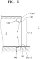
- FIG. 5 is a cross-sectional view of the blocking device illustrated in FIG. 4 .
- a vertical flow device may eject the purified air toward the purification space 2 at an angle with respect to the vertical direction.
- the downward air discharge port 131 and the upward air discharge port 141 may be formed to be inclined toward the purification space 2 with respect to the vertical direction. According to this configuration, because the purified air ejected through the downward air discharge port 131 and the upward air discharge port 141 may be directed toward the purification space 2, the amount of leakage of the purified air to the external space 1 may be reduced.
- FIG. 6 is a diagram illustrating some example embodiments of a blocking device not falling under the scope of the claims.
- the air supply structure for supplying the purified air from the air purifying device 4 to the purification space 2 is omitted and only the structure of the blocking device is illustrated.
- a first opening 31a is provided in the side wall 32.
- the blocking device may include a horizontal blocking device 150 installed at one or more of horizontal edges 31a-3 and 31a-4 of the first opening 31a to eject the purified air horizontally across the first opening 31a.
- the horizontal blocking device 150 may be connected to the air purifying device 4 to eject the purified air supplied from the air purifying device 4.
- the horizontal blocking device 150 may intake and eject the air inside the purification space 2.
- the horizontal blocking device 150 may be installed at each of the horizontal edges 31a-3 and 31a-4 of the first opening 31a to eject the air in the opposite directions in the horizontal direction.
- the horizontal blocking device 150 may be connected to the air purifying device 4 and may include an air discharge port 151 that is open in the horizontal direction.
- the air discharge port 151 may have a shape extending in the vertical direction along the horizontal edges 31a-3 and 31a-4.
- the air discharge port 151 may be implemented by a plurality of air discharge ports arranged in the vertical direction.
- the horizontal blocking device 150 may include a blower for discharging the purified air received from the air purifying device 4 or the air of the purification space 2, through the air discharge port 151.
- An air flow 155 may be formed horizontally across the first opening 31a by the horizontal blocking device 150.
- the air flow 155 may function as an air curtain intersecting the first opening 31a in the horizontal direction.
- the blocking device illustrated in FIG. 4 may be applied to the blocking device illustrated in FIG. 6 .
- FIG. 7 is a cross-sectional view of the blocking device illustrated in FIG. 6 .
- the horizontal blocking device 150 may eject the purified air toward the purification space 2 at an angle with respect to the horizontal direction.
- the air discharge port 151 may be formed to be inclined toward the purification space 2 with respect to the horizontal direction. According to this configuration, because the purified air ejected through the air discharge port 151 may be directed toward the purification space 2, the amount of leakage of the purified air to the external space 1 may be reduced.
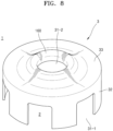
- FIG. 8 is a diagram illustrating some example embodiments of a blocking device not falling under the scope of the claims.
- the main supply structure for supplying the purified air from the air purifying device 4 to the purification space 2 is omitted and only the structure of the blocking device is illustrated.
- a partition 3 includes a side wall 32 forming a horizontal boundary of the purification space 2 and an upper wall 33 forming a vertical boundary of the purification space 2.
- a plurality of first openings 31-1 may be provided in the side wall 32.
- a second opening 31-2 may be provided in the upper wall 33.
- the blocking device of some example embodiments may reduce or prevent the external air from flowing into the purification space 2 through the second opening 31-2, by using the flow of air flowing along the upper wall 33 in the external space 1.
- the blocking device may be implemented by a streamlined dome structure 160 provided around the second opening 31-2.
- the streamlined dome structure 160 may have a shape for guiding the external air flowing along the outer surface thereof to flow outside across the second opening 31-2.
- the external air may be reduced or prevented from flowing into the purification space 2 through the second opening 31-2 or the inflow thereof may be reduced.
- a negative pressure may be generated around the second opening 31-2.
- a flow of air from the purification space 2 toward the external space 1 may be formed around the second opening 31-2, it may be difficult for the external air to pass through the second opening 31-2 and then flow into the purification space 2.
- Example embodiments of the air cleaning system described above may be applied in various ways.
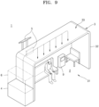
- FIG. 9 is a perspective view illustrating an example of an air cleaning system installed at a bus stop not falling under the scope of the claims.
- a purification space 2 may be defined by a partition 3.
- the purification space 2 may be a waiting space for a passenger waiting for a bus.
- An opening 31 may function as an entrance for the passenger.
- the air purifying device 4 may be installed outside a side wall 32.
- the air purifying device 4 may supply purified air to the purification space 2.
- the temperature adjusting device 6 may adjust the internal temperature of the purification space 2.
- At least a portion of the side wall 32 and an upper wall 33 may be transparent.
- a solar cell may be installed on the upper wall 33.
- the blocking devices illustrated in FIGS. 3 to 7 may be applied to the air cleaning system of the bus stop illustrated in FIG. 9 .
- FIG. 10 is a perspective view illustrating an example of an air cleaning system installed at a bus terminal not falling under the scope of the claims.
- a purification space 2 may be defined by a partition 3.
- the partition 3 may be implemented by a side wall 32, an upper wall 33, and one side wall 8 of the main building of the bus terminal.
- the purification space 2 may be a bus boarding space.
- An opening 31 provided in the side wall 32 may function as an entrance for a bus.
- a passenger may enter and exit the purification space 2 through the opening 31.
- the passenger may enter and exit the purification space 2 through an entrance provided at one side wall 8 of the main building of the bus terminal.
- At least a portion of the side wall 32 and the upper wall 33 may be transparent.
- a solar cell may be installed on the upper wall 33.
- the air purifying device 4 may be installed outside the purification space 2 and may supply purified air to the purification space 2 through a duct (not illustrated).
- the temperature adjusting device 6 may adjust the internal temperature of the purification space 2.
- the blocking devices illustrated in FIGS. 3 to 7 may be applied to the air cleaning system of the bus terminal illustrated in FIG. 10 .
- FIG. 11 is a perspective view illustrating an example of an air cleaning system installed at a playground not falling under the scope of the claims.
- the structure of the partition 3 illustrated in FIG. 2 may be used to define a purification space 2 by surrounding a playground in which a plurality of play apparatuses are installed.
- the partition 3 of some example embodiments may include a side wall 32 that is generally cylindrical and an upper wall 33 forming a roof.
- a plurality of first openings 31-1 may be provided in the side wall 32.
- the plurality of first openings 31-1 may function as an entrance to the purification space 2.
- At least a portion of the side wall 32 and the upper wall 33 may be transparent.
- Second openings 31-2 and 31-3 may be provided in the upper wall 33 to improve the openness of the playground.
- the second openings 31-2 and 31-3 may be opened and closed by movable walls 34-1 and 34-2.
- the controller 9 may drive the movable walls 34-1 and 34-2 to close the second openings 31-2 and 31-3 or to partially or entirely open the second openings 31-2 and 31-3.
- the movable walls 34-1 and 34-2 may be transparent.
- a movable wall for opening and closing the first opening 31-1 may be provided.
- the air purifying device 4 may supply purified air to the purification space 2.
- the temperature adjusting device 6 may adjust the internal temperature of the purification space 2.
- the blocking devices illustrated in FIGS. 3 to 7 may be applied to the air cleaning system of the playground illustrated in FIG. 11 .
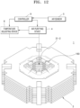
- FIG. 12 is a perspective view illustrating an example of an air cleaning system installed in a courtyard of a building not falling under the scope of the claims.
- the courtyard may be a purification space 2.
- a partition 3 may be implemented by the buildings that horizontally surround the courtyard.
- An upper portion of the courtyard may be opened by a second opening 31-2.
- the air purifying device 4 may supply purified air to the purification space 2.
- the temperature adjusting device 6 may adjust the internal temperature of the purification space 2.
- FIG. 8 may be applied as a blocking device for blocking the purified air from flowing out from the purification space 2 through the second opening 31-2.
- the blocking device may be implemented by a streamlined dome structure 160 provided around the second opening 31-2.
- processing circuitry such as hardware including logic circuits; a hardware/software combination such as a processor executing software; or a combination thereof.
- the processing circuitry more specifically may include, but is not limited to, a central processing unit (CPU) , an arithmetic logic unit (ALU), a digital signal processor, a microcomputer, a field programmable gate array (FPGA), a System-on-Chip (SoC), a programmable logic unit, a microprocessor, application-specific integrated circuit (ASIC), etc.
- CPU central processing unit
- ALU arithmetic logic unit
- FPGA field programmable gate array
- SoC System-on-Chip
- ASIC application-specific integrated circuit
- the air cleaning system it may be possible to more efficiently clean outdoor air by forming a purification space somewhat isolated from the external space while maintaining some sense of openness.
Landscapes
- Engineering & Computer Science (AREA)
- Chemical & Material Sciences (AREA)
- Combustion & Propulsion (AREA)
- Mechanical Engineering (AREA)
- General Engineering & Computer Science (AREA)
- Architecture (AREA)
- Chemical Kinetics & Catalysis (AREA)
- Civil Engineering (AREA)
- Structural Engineering (AREA)
- Electromagnetism (AREA)
- Analytical Chemistry (AREA)
- General Chemical & Material Sciences (AREA)
- Oil, Petroleum & Natural Gas (AREA)
- Physics & Mathematics (AREA)
- Central Air Conditioning (AREA)
- Air-Flow Control Members (AREA)
Description
- The present invention relates to air cleaning systems installed outdoors.
- As air pollution due to particulate matter (PM), harmful gas, or the like becomes more severe, attempts to purify air in particular outdoor regions for safe outdoor activities are underway. Such attempts to purify outdoor air include a method of manufacturing an existing indoor air purifying device in a large size and installing it outdoors, a method of washing out pollutants by artificial rainfall, an air flow method based on destruction of an inversion layer of the atmosphere, or the like. However, in the above methods, due to an air flow occurring in an open outdoor space or the like, a large air purification facility is required to secure a large purification zone and also it is not easy to efficiently removing pollutants such as particulate matter.
- Korean Patent Publication Number
KR 102 050 298 B1 -
CN 105587139 B presents an intelligent watchhouse and an ambient condition which can be adjusted using the intelligent watchhouse. The intelligent watchhouse includes a police platform and a ceiling. -
KR 2015 0118464 claim 1 is based. - Provided are air cleaning systems capable of efficiently forming a purification zone in an outdoor space.
- Additional aspects will be set forth in part in the description which follows and, in part, will be apparent from the description, or may be learned by practice of example embodiments of the disclosure.
- According to the invention, there is provided an outdoor air cleaning system according to
claim 1. - The openness level may be about 20 % or more.
- A volume of the purification space may be about 100,000 cubic meters or less.
- At least a portion of the partition may be transparent.
- The outdoor air cleaning system may further include a movable wall arranged to open and close at least a portion of the opening.
- The outdoor air cleaning system may further include a temperature adjusting device configured to form a temperature gradient between the purification space and the external space.
- The vertical blocking device may eject the purified air toward the purification space at an angle with respect to a vertical direction.
- The blocking device may include a horizontal blocking device at a horizontal edge of the first opening configured to eject the purified air supplied from the air purifying device horizontally across the first opening.
- The horizontal blocking device may be configured to eject the purified air toward the purification space at an angle with respect to a horizontal direction.
- The opening may include a second opening in the upper wall, and the blocking device may include a streamlined dome structure around the second opening.
- The above and other aspects, features, and advantages of some example embodiments of the disclosure will be more apparent from the following description taken in conjunction with the accompanying drawings, in which:
-
FIG. 1 is a configuration diagram of an air cleaning system according to some example embodiments, not falling under the scope of the claims; -
FIG. 2 illustrates a partition according to some example embodiments, not falling under the scope of the claims; -
FIG. 3 is a diagram illustrating a blocking device according to some example embodiments, not falling under the scope of the claims; -
FIG. 4 is a diagram illustrating a blocking device according to the invention; -
FIG. 5 is a cross-sectional view of the blocking device illustrated inFIG. 4 according to the invention; -
FIG. 6 is a diagram illustrating a blocking device according to some example embodiments, not falling under the scope of the claims; -
FIG. 7 is a cross-sectional view of the blocking device illustrated inFIG. 6 according to some example embodiments, not falling under the scope of the claims; -
FIG. 8 is a diagram illustrating a blocking device according to some example embodiments, not falling under the scope of the claims; -
FIG. 9 is a perspective view illustrating an example of an air cleaning system installed at a bus stop according to some example embodiments, not falling under the scope of the claims; -
FIG. 10 is a perspective view illustrating an example of an air cleaning system installed at a bus terminal according to some example embodiments, not falling under the scope of the claims; -
FIG. 11 is a perspective view illustrating an example of an air cleaning system installed at a playground according to some example embodiments, not falling under the scope of the claims; and -
FIG. 12 is a perspective view illustrating an example of an air cleaning system installed in a courtyard of a building according to some example embodiments, not falling under the scope of the claims. - Reference will now be made in detail to example embodiments, examples of which are illustrated in the accompanying drawings, wherein like reference numerals refer to like elements throughout. In this regard, the present example embodiments may have different forms and should not be construed as being limited to the descriptions set forth herein. Accordingly, some example embodiments are merely described below, by referring to the figures, to explain aspects. As used herein, the term "and/or" includes any and all combinations of one or more of the associated listed items. Expressions such as "at least one of," when preceding a list of elements, modify the entire list of elements and do not modify the individual elements of the list.
- Hereinafter, some example embodiments of the present invention will be described in detail with reference to the accompanying drawings. In the drawings, like reference numerals may denote like elements, and the size of each element may be exaggerated for clarity and convenience of description.
-
FIG. 1 is a configuration diagram of an air cleaning system according to some example embodiments, not falling under the scope of the claims. Referring toFIG. 1 , according to some example embodiments, an air cleaning system includes apartition 3 defining apurification space 2 and an air purifyingdevice 4 supplying purified air to thepurification space 2. Thepartition 3 surrounds thepurification space 2 to isolate thepurification space 2 from anexternal space 1. Thepartition 3 has one ormore openings 31 connecting thepurification space 2 to theexternal space 1. Thepurification space 2 may be, for example, a bus stop, a playground, a resting space in a park, a bus terminal, a school playground, an outdoor sports stadium, a courtyard of a building, or the like. - The
partition 3 may be an artificial structure for isolating thepurification space 2 from theexternal space 1. For example, thepartition 3 may surround a bus stop, a playground, a bus terminal, or a resting space in a park to partially isolate the bus stop, the playground, the bus terminal, or the resting space in the park from theexternal space 1. Also, thepartition 3 may be implemented by a structure itself requiring thepurification space 2. For example, in the case of a sports stadium, thepartition 3 may be implemented by a structure including a grandstand and a wall surrounding a central sports ground. In the case of a courtyard of a building, thepartition 3 may be implemented by a building structure surrounding the courtyard. - The
purification space 2 may be connected to theexternal space 1 by theopening 31. That is, the openness of thepurification space 2 may be maintained by theopening 31. The opening 31 may have a size capable of ensuring the own utility of thepurification space 2. For example, in the case of a bus stop, theopening 31 may have a position, shape, and size for functioning as a passage for a passenger waiting for a bus to move from theexternal space 1 to thepurification space 2 and vice versa. In the case of a playground, a resting space in a park, an outdoor sports stadium, or the like, the opening 31 may have a position, shape, and size for functioning as an access passage of users, and anadditional opening 31 may be formed in thepartition 3 such that the playground, the resting space in the park, the outdoor athletic stadium, or the like may be open toward the sky. In the case of a courtyard of a building, the opening 31 may be formed in thepartition 3 such that the courtyard may be open (upward) toward the sky. One ormore openings 31 may be formed in thepartition 3 to maintain the functionality and openness suitable for the purpose of use of the facility to which the air cleaning system is applied. - The air purifying
device 4 may be a filter device, an electrostatic device, a plasma device, a catalyst device, and/or an adsorption device and may purify the air by various purification methods such as a filter method, an electrostatic method, a plasma method, a catalyst method, and/or an adsorption method. The purified air may be supplied to thepurification space 2. The air purifyingdevice 4 may be installed outside thepartition 3 to purify the air of theexternal space 1 and supply the purified air to thepurification space 2. Theair purifying device 4 may be installed in thepurification space 2 to purify the air inside thepurification space 2. Theair purifying device 4 may be installed in each of theexternal space 1 and thepurification space 2. Theair purifying device 4 may be manufactured to supply purified air having a concentration of particulate matter reduced by about 50 % or more in comparison with the external air, for example, based on PM2.5 (particulate matters with diameter of equal to or less than 2.5µm). - The air cleaning system may include an
air sensor 5 for measuring the air quality. Theair sensor 5 may be installed in theexternal space 1 or thepurification space 2 or both. Theair sensor 5 may measure the air quality inside thepurification space 2. Theair sensor 5 may measure the air quality of theexternal space 1 around thepurification space 2. - The
air sensor 5 may include aparticulate matter sensor 53 for measuring a concentration of particulate matter in the air. Theair sensor 5 may further include atemperature sensor 51 and ahumidity sensor 52 for measuring the temperature and humidity of air. Although not illustrated in the drawings, theair sensor 5 may further include a wind speed sensor for measuring a flow rate of air in theexternal space 1, a gas detection sensor for detecting a gas component in the air of thepurification space 2, or the like. - Various types of known sensors may be used as the
particulate matter sensor 53. For example, theparticulate matter sensor 53 may include a flow meter unit for inducing an air flow and measuring a flow rate and a sensing unit for detecting particulate matter in the air. The sensing unit may be a light scattering device, a weight device, and/or an inertial mass device and may measure the amount of particulate matter in the air by various detection methods, for example, light scattering type, weight type, and/or inertial mass type. The light scattering type detection method may irradiate light to a measurement region through which air passes and receive light scattered by particulate matter to measure the amount of particulate matter. The weight-type detection method may pass air through a filter in a sensor, collect particulate matter, and measure the amount of collected particulate matter. The inertial mass-type detection method may set particulate matter to settle at a particular position and then indirectly measure its weight. - A
controller 9 may control theair purifying device 4 based on the detection value of theair sensor 5. Thecontroller 9 may turn on/off theair purifying device 4 or control the operation speed of theair purifying device 4 based on the detection value of theair sensor 5. - According to an outdoor air cleaning system of the related art, the
air purifying device 4 is installed in theexternal space 1. The purified air is supplied around theair purifying device 4. Because thepurification space 2 to which the purified air is supplied is not isolated from theexternal space 1, the flow of air generated in theexternal space 1 passes through thepurification space 2 as it is. Thus, even when the purified air is supplied to thepurification space 2, the purified air is difficult to maintain in thepurification space 2, and because the air thereof is mixed with the unpurified air introduced from theexternal space 1, the air cleanliness level of thepurification space 2 is difficult to maintain. Also, because the capacity of theair purifying device 4 required per unit volume of thepurification space 2 that may be secured is so large, it is difficult to secure the economic efficiency and utility. - According to some example embodiments not according to the invention, the
purification space 2 may be partially isolated from theexternal space 1 by thepartition 3. The air inside thepurification space 2 and the air in theexternal space 1 may be partially isolated from each other by thepartition 3. The influence of the air flow of theexternal space 1 on thepurification space 2 may be reduced and thus the mixing of the purified air supplied to thepurification space 2 and the unpurified air of theexternal space 1 may be reduced. Also, thepurification space 2 may be partitioned by thepartition 3 as a space in which the purified air may stay and circulate. Because thepurification space 2 may be partially isolated from theexternal space 1, the air cleanliness level of thepurification space 2 may be maintained at a suitable level by using theair purifying device 4 having a smaller purification capacity than the outdoor air cleaning system of the related art. This may mean the improvement of the air purification efficiency against the cost of the air cleaning system and may ensure the feasibility of the outdoor air cleaning system. - The size and/or number of the
openings 31 may be determined considering the openness of thepurification space 2 and the functionality of theopening 31. The size of theopening 31 may be defined by an openness level defined as an area ratio of theopening 31 with respect to the surface area of thepartition 3, as represented in the following equation.
- As a minimum condition for securing the openness of the
purification space 2 and the functionality of theopening 31, the openness level is about 10 % or more. When the openness level is less than about 10 %, thepurification space 2 may not be distinguished from the internal space of the building and may be substantially difficult to consider as an outdoor air cleaning system. - The openness level of the
partition 3 may be about 20 % or more in order to define arealistic purification space 2 that is capable of securing the openness and functionality and is installed in an outdoor place such as a bus stop, a playground, a bus terminal, or a resting space in a park. - An excessively great openness level may be disadvantageous for maintaining the air cleanliness level of the
purification space 2. The upper limit of the openness level may be determined considering the efficiency and the economic efficiency of the installation cost of theair purifying device 4 capable of maintaining the air cleanliness level of thepurification space 2 at a desired level while securing the openness of thepurification space 2 and the functionality of theopening 31. Considering this point, the openness level is about 50 % or less and accordingly a particulate matter reduction efficiency of about 50 % or more of thepurification space 2 may be implemented. Also, the clean air maintenance efficiency of thepurification space 2 may be maintained at about 50 % or more. - The
partition 3 includes aside wall 32 forming a horizontal boundary of thepurification space 2 and anupper wall 33 forming a vertical boundary of thepurification space 2. One ormore openings 31 are provided in at least one of theside wall 32 and theupper wall 33. In some example embodiments illustrated inFIG. 1 , oneopening 31 is provided in theside wall 32. The area of theopening 31 is about 10 % or more of the surface area of theupper wall 33 and theside wall 32 including theopening 31. Considering the openness and functionality, the area of theopening 31 may be about 20% or more of the surface area of theupper wall 33 and theside wall 32 including theopening 31. Considering the efficiency and the economic efficiency of the air cleaning system, the area of theopening 31 is about 50% or less of the surface area of theupper wall 33 and theside wall 32 including theopening 31. - In order to implement higher openness even at a lower openness level, at least a portion of the
partition 3 may be transparent. For example, at least a portion of theside wall 32 may be transparent and theupper wall 33 may also be partially or entirely transparent. Although not illustrated in the drawings, a solar cell for solar power generation may be installed on theupper wall 33. For example, the air cleaning system may include an energy storage system (ESS) for storing electricity generated by the solar cell. The electricity stored in the energy storage system may be used as energy for driving theair purifying device 4, theair sensor 5, atemperature adjusting device 6, thecontroller 9, and/or the like. Accordingly, an eco-friendly air cleaning system may be implemented. - When the volume of the
purification space 2 is excessive, the installation cost of theair purifying device 4 for maintaining the air cleanliness level of thepurification space 2 may increase excessively and thus the efficiency and the economic efficiency thereof may decrease. Considering this point, the volume of thepurification space 2 may be about 100,000 cubic meters or less. - When the air cleanliness level inside the
purification space 2 is very low, it may be necessary to rapidly increase the air cleanliness level of thepurification space 2. For example, in the case of a bus stop, a playground, a resting space in a park, a school playground, a bus terminal, a courtyard of a building, or the like, thecontroller 9 may not operate theair purifying device 4 at midnight because there is no user at midnight. In the case of a sports stadium, thecontroller 9 may not operate theair purifying device 4 while it is not in use. For example, the air cleanliness level of thepurification space 2 may decrease. When the bus stop, the playground, the resting space in the park, the school playground, the bus terminal, the courtyard of the building, or the like is to be re-used in the daytime, or when the sports stadium is to be used, it may be necessary to rapidly increase the air cleanliness level of thepurification space 2. - For this purpose, the air cleaning system may include a movable barrier or
movable wall 34 for opening and closing at least a portion of theopening 31. When it is necessary to rapidly increase the air cleanliness level of thepurification space 2, thecontroller 9 may drive themovable wall 34 to entirely or partially block theopening 31 to isolate thepurification space 2 from theexternal space 1 and may drive theair purifying device 4 to supply purified air to thepurification space 2. Accordingly, the air cleanliness level of thepurification space 2 may be rapidly increased. When the air cleanliness level of thepurification space 2 reaches a target cleanliness level, thecontroller 9 may drive themovable wall 34 to open theopening 31. - The
movable wall 34 of some example embodiments may be rotatably installed at theside wall 32 to be moved to a position for opening theopening 31 and a position for closing theopening 31. The shape of themovable wall 34 may vary according to various example embodiments. For example, themovable wall 34 may be implemented in a bellows (or accordion) shape that may be installed at theside wall 32 or theupper wall 33 to be reduced/expanded in the vertical direction. Although not illustrated in the drawings, when theopening 31 is provided in theupper wall 33, themovable wall 34 may be installed at theupper wall 33. - The
movable wall 34 may be used to open and close theopening 31 to protect thepurification space 2 in response to external weather change. -
FIG. 2 illustrates some example embodiments, not falling under the scope of the claims, of thepartition 3. Referring toFIG. 2 , apartition 3 may be generally cylindrical and may isolate apurification space 2 from anexternal space 1. A plurality of first openings 31-1 may be provided in aside wall 32 forming a horizontal boundary of thepurification space 2. The plurality of first openings 31-1 may function as an entrance to thepurification space 2. Anupper wall 33 forming a vertical boundary of thepurification space 2 may function as a roof. Second openings 31-2 and 31-3 may be provided in theupper wall 33. Movable walls 34-1 and 34-2 may be provided to open and close the second openings 31-2 and 31-3, respectively. Although not illustrated in the drawings, a movable wall for opening and closing the first opening 31-1 may be provided. At least a portion of theside wall 32 may be transparent. At least a portion of theupper wall 33 may be transparent. For example, the movable walls 34-1 and 34-2 may be transparent. - The sum of the areas of the first openings 31-1 and the second openings 31-2 and 31-3 is about 10 % or more of the surface area of the
side wall 32 and theupper wall 33. Considering the openness and functionality, the sum of the areas of the first openings 31-1 and the second openings 31-2 and 31-3 may be about 20% or more of the surface area of theside wall 32 and theupper wall 33. Considering the efficiency and the economic efficiency of the air cleaning system, the sum of the areas of the first openings 31-1 and the second openings 31-2 and 31-3 is about 50% or less of the surface area of theside wall 32 and theupper wall 33. Thepurification space 2 may be, for example, a playground, a school playground, a resting space in a park, or the like. - The
partition 3 is not limited to the examples illustrated inFIGS. 1 and2 and may be implemented in various shapes including functional and aesthetic structures. - Referring back to
FIG. 1 , the air cleaning system may further include thetemperature adjusting device 6. Thetemperature adjusting device 6 may adjust the internal temperature of thepurification space 2. Thetemperature adjusting device 6 may include, for example, an air conditioner (cooler) and/or a heater. Thetemperature adjusting device 6 may receive purified air from theair purifying device 4, cool or heat the purified air to a desired temperature, and supply the resulting air to thepurification space 2. Thetemperature adjusting device 6 may be installed inside thepurification space 2 to cool or heat the purified air to a desired temperature. - By the purified air supplied from the
air purifying device 4, the air cleanliness level inside thepurification space 2 may be maintained at a suitable level. According to the air cleaning system of some example embodiments, thepurification space 2 may be connected to theexternal space 1 through theopening 31. Thus, the external unpurified air may flow into thepurification space 2 through theopening 31. Thus, a blocking device is required to block the external unpurified air from flowing into thepurification space 2 through theopening 31. - As an example, the
temperature adjusting device 6 may form a temperature gradient between thepurification space 2 and theexternal space 1 such that air may not flow into thepurification space 2 through the opening 31 from theexternal space 1. That is, thetemperature adjusting device 6 may form a temperature gradient between the purified air in thepurification space 2 and the external air in theexternal space 1. The purified air and the external air meet each other at theopening 31. Due to the temperature difference between the purified air and the external air, the external air may be partially blocked from flowing into thepurification space 2 through theopening 31. Accordingly, thetemperature adjusting device 6 may function as a blocking device. - As an example, the air flow inside the
purification space 2 may be used to reduce or prevent the unpurified air from flowing into thepurification space 2 or to allow only a little of the unpurified air to flow thereinto.FIG. 3 is a diagram illustrating some example embodiments of a blocking device. In some example embodiments, an air supply structure itself for supplying air to thepurification space 2 may also function as a blocking device. Referring toFIG. 3 , the air cleaning system may include avertical flow device 110 that may receive the purified air from theair purifying device 4 and form adownward air flow 113 from an upper portion of thepurification space 2. The blocking device may include ahorizontal flow device 120 that may receive the purified air from theair purifying device 4 and form ahorizontal air flow 123 along theside wall 32 inside thepurification space 2. - The
vertical flow device 110 may be connected to theair purifying device 4 and may be installed at theupper wall 33. Thevertical flow device 110 may include anair discharge port 112 that is open downward. Theair discharge port 112 may have a shape extending in the horizontal direction. Although not illustrated in the drawings, theair discharge port 112 may be implemented by a plurality of air discharge ports arranged in the horizontal direction. Although not illustrated in the drawings, thevertical flow device 110 may include a blower for discharging the purified air received from theair purifying device 4, through theair discharge port 112. The blower may be controlled by thecontroller 9. - The
horizontal flow device 120 may be connected to theair purifying device 4 and may be installed at theside wall 32. Thehorizontal flow device 120 may include anair discharge port 122 that is open in the horizontal direction. Theair discharge port 122 may have a shape extending in the vertical direction. Although not illustrated in the drawings, theair discharge port 122 may be implemented by a plurality of air discharge ports arranged in the vertical direction. Although not illustrated in the drawings, thehorizontal flow device 120 may include a blower for discharging the purified air received from theair purifying device 4, through theair discharge port 122. The blower may be controlled by thecontroller 9. - According to this configuration, the
downward air flow 113 and thehorizontal air flow 123 may be merged with each other to form an air flow circulating in the horizontal direction along theside wall 32 inside thepurification space 2 as a whole. The air flow circulating in the horizontal direction may form a blocking wall for blocking the unpurified external air introduced through theopening 31. Thus, the external air flowing into thepurification space 2 through theopening 31 provided in theside wall 32 or the openings 32-1, 33-1, and 33-2 provided in theside wall 32 and theupper wall 33 as illustrated inFIG. 2 may be blocked or the amount of the external air flowing thereinto may be reduced. - The
horizontal flow device 120 may eject the purified air toward thepurification space 2 at an angle with respect to the horizontal direction. For example, theair discharge port 122 may be formed to be inclined toward thepurification space 2 with respect to the horizontal direction. According to this configuration, because the purified air ejected through theair discharge port 122 may be directed toward thepurification space 2, the amount of leakage of the purified air to theexternal space 1 may be reduced. -
FIG. 4 is a diagram illustrating a blocking device according to the invention. InFIG. 4 , the air supply structure for supplying the purified air from theair purifying device 4 to thepurification space 2 is omitted and only the structure of the blocking device is illustrated. Referring toFIG. 4 , afirst opening 31a is provided in theside wall 32. The blocking device includes a vertical blocking device installed at a vertical edge of thefirst opening 31a to eject the purified air vertically across thefirst opening 31a. The vertical blocking device is connected to theair purifying device 4 to eject the purified air supplied from theair purifying device 4. The vertical blocking device may intake and eject the air inside thepurification space 2. - The vertical edge of the
first opening 31a may include anupper edge 31a-1. The vertical blocking device may include adownward blocking device 130 installed at theupper edge 31a-1 of thefirst opening 31 to eject the purified air downward. Thedownward blocking device 130 may include anair discharge port 131 that is open downward. Theair discharge port 131 may have a shape extending in the horizontal direction along theupper edge 31a-1. Although not illustrated in the drawings, theair discharge port 131 may be implemented by a plurality of air discharge ports arranged in the horizontal direction. Although not illustrated in the drawings, thedownward blocking device 130 may include a blower for discharging the purified air received from theair purifying device 4 or the air inside thepurification space 2, through theair discharge port 131. Adownward air flow 135 may be formed vertically across thefirst opening 31a by thedownward blocking device 130. Thedownward air flow 135 may function as an air curtain intersecting thefirst opening 31a in the vertical direction. Thus, because unpurified air may be blocked by thedownward air flow 135, the unpurified air may not flow into thepurification space 2 through thefirst opening 31a or the inflow thereof may be reduced. - The vertical edge of the
first opening 31a includes alower edge 31a-2. The vertical blocking device includes anupward blocking device 140 installed at thelower edge 31a-2 of thefirst opening 31 to eject the purified air upward. Thelower edge 31a-2 of thefirst opening 31 may be substantially a floor on which thepartition 3 is installed. Theupward blocking device 140 may be connected to theair purifying device 4 and may include anair discharge port 141 that is open upward. Theair discharge port 141 may have a shape extending in the horizontal direction along thelower edge 31a-2. Although not illustrated in the drawings, theair discharge port 141 may be implemented by a plurality of air discharge ports arranged in the horizontal direction. Although not illustrated in the drawings, theupward blocking device 140 may include a blower for discharging the purified air received from theair purifying device 4 or the air inside thepurification space 2, through theair discharge port 141. Anupward air flow 145 may be formed vertically across thefirst opening 31a by theupward blocking device 140. Theupward air flow 145 may function as an air curtain intersecting thefirst opening 31a in the vertical direction. Thus, because unpurified air may be blocked by theupward air flow 145, the unpurified air may not flow into thepurification space 2 through thefirst opening 31a or the inflow thereof may be reduced. Also, because theupward blocking device 140 may block the external air flowing near the floor, theupward blocking device 140 may effectively block the dust on the floor from flowing into thepurification space 2. -
FIG. 5 is a cross-sectional view of the blocking device illustrated inFIG. 4 . Referring toFIG. 5 , a vertical flow device may eject the purified air toward thepurification space 2 at an angle with respect to the vertical direction. For example, the downwardair discharge port 131 and the upwardair discharge port 141 may be formed to be inclined toward thepurification space 2 with respect to the vertical direction. According to this configuration, because the purified air ejected through the downwardair discharge port 131 and the upwardair discharge port 141 may be directed toward thepurification space 2, the amount of leakage of the purified air to theexternal space 1 may be reduced. -
FIG. 6 is a diagram illustrating some example embodiments of a blocking device not falling under the scope of the claims. InFIG. 6 , the air supply structure for supplying the purified air from theair purifying device 4 to thepurification space 2 is omitted and only the structure of the blocking device is illustrated. Referring toFIG. 6 , afirst opening 31a is provided in theside wall 32. The blocking device may include ahorizontal blocking device 150 installed at one or more ofhorizontal edges 31a-3 and 31a-4 of thefirst opening 31a to eject the purified air horizontally across thefirst opening 31a. Thehorizontal blocking device 150 may be connected to theair purifying device 4 to eject the purified air supplied from theair purifying device 4. Thehorizontal blocking device 150 may intake and eject the air inside thepurification space 2. - In some example embodiments, the
horizontal blocking device 150 may be installed at each of thehorizontal edges 31a-3 and 31a-4 of thefirst opening 31a to eject the air in the opposite directions in the horizontal direction. Thehorizontal blocking device 150 may be connected to theair purifying device 4 and may include anair discharge port 151 that is open in the horizontal direction. Theair discharge port 151 may have a shape extending in the vertical direction along thehorizontal edges 31a-3 and 31a-4. Although not illustrated in the drawings, theair discharge port 151 may be implemented by a plurality of air discharge ports arranged in the vertical direction. Although not illustrated in the drawings, thehorizontal blocking device 150 may include a blower for discharging the purified air received from theair purifying device 4 or the air of thepurification space 2, through theair discharge port 151. Anair flow 155 may be formed horizontally across thefirst opening 31a by thehorizontal blocking device 150. Theair flow 155 may function as an air curtain intersecting thefirst opening 31a in the horizontal direction. Thus, because unpurified air may be blocked by theair flow 155, the unpurified air may not flow into thepurification space 2 through thefirst opening 31a or the inflow thereof may be reduced. The blocking device illustrated inFIG. 4 may be applied to the blocking device illustrated inFIG. 6 . -
FIG. 7 is a cross-sectional view of the blocking device illustrated inFIG. 6 . Referring toFIG. 7 , thehorizontal blocking device 150 may eject the purified air toward thepurification space 2 at an angle with respect to the horizontal direction. For example, theair discharge port 151 may be formed to be inclined toward thepurification space 2 with respect to the horizontal direction. According to this configuration, because the purified air ejected through theair discharge port 151 may be directed toward thepurification space 2, the amount of leakage of the purified air to theexternal space 1 may be reduced. -
FIG. 8 is a diagram illustrating some example embodiments of a blocking device not falling under the scope of the claims. InFIG. 8 , the main supply structure for supplying the purified air from theair purifying device 4 to thepurification space 2 is omitted and only the structure of the blocking device is illustrated. Referring toFIG. 8 , apartition 3 includes aside wall 32 forming a horizontal boundary of thepurification space 2 and anupper wall 33 forming a vertical boundary of thepurification space 2. A plurality of first openings 31-1 may be provided in theside wall 32. A second opening 31-2 may be provided in theupper wall 33. The blocking device of some example embodiments may reduce or prevent the external air from flowing into thepurification space 2 through the second opening 31-2, by using the flow of air flowing along theupper wall 33 in theexternal space 1. For example, referring toFIG. 8 , the blocking device may be implemented by astreamlined dome structure 160 provided around the second opening 31-2. Thestreamlined dome structure 160 may have a shape for guiding the external air flowing along the outer surface thereof to flow outside across the second opening 31-2. By this configuration, the external air may be reduced or prevented from flowing into thepurification space 2 through the second opening 31-2 or the inflow thereof may be reduced. Also, when the external airflows across the second opening 31-2 along thestreamlined dome structure 160, a negative pressure may be generated around the second opening 31-2. Thus, because a flow of air from thepurification space 2 toward theexternal space 1 may be formed around the second opening 31-2, it may be difficult for the external air to pass through the second opening 31-2 and then flow into thepurification space 2. - Example embodiments of the air cleaning system described above may be applied in various ways.
-
FIG. 9 is a perspective view illustrating an example of an air cleaning system installed at a bus stop not falling under the scope of the claims. Referring toFIG. 9 , apurification space 2 may be defined by apartition 3. Thepurification space 2 may be a waiting space for a passenger waiting for a bus. Anopening 31 may function as an entrance for the passenger. Theair purifying device 4 may be installed outside aside wall 32. Theair purifying device 4 may supply purified air to thepurification space 2. Thetemperature adjusting device 6 may adjust the internal temperature of thepurification space 2. At least a portion of theside wall 32 and anupper wall 33 may be transparent. A solar cell may be installed on theupper wall 33. The blocking devices illustrated inFIGS. 3 to 7 may be applied to the air cleaning system of the bus stop illustrated inFIG. 9 . -
FIG. 10 is a perspective view illustrating an example of an air cleaning system installed at a bus terminal not falling under the scope of the claims. Referring toFIG. 10 , apurification space 2 may be defined by apartition 3. Thepartition 3 may be implemented by aside wall 32, anupper wall 33, and oneside wall 8 of the main building of the bus terminal. Thepurification space 2 may be a bus boarding space. Anopening 31 provided in theside wall 32 may function as an entrance for a bus. A passenger may enter and exit thepurification space 2 through theopening 31. Also, although not illustrated in the drawings, the passenger may enter and exit thepurification space 2 through an entrance provided at oneside wall 8 of the main building of the bus terminal. At least a portion of theside wall 32 and theupper wall 33 may be transparent. A solar cell may be installed on theupper wall 33. Theair purifying device 4 may be installed outside thepurification space 2 and may supply purified air to thepurification space 2 through a duct (not illustrated). Thetemperature adjusting device 6 may adjust the internal temperature of thepurification space 2. The blocking devices illustrated inFIGS. 3 to 7 may be applied to the air cleaning system of the bus terminal illustrated inFIG. 10 . -
FIG. 11 is a perspective view illustrating an example of an air cleaning system installed at a playground not falling under the scope of the claims. Referring toFIG. 11 , the structure of thepartition 3 illustrated inFIG. 2 may be used to define apurification space 2 by surrounding a playground in which a plurality of play apparatuses are installed. Thepartition 3 of some example embodiments may include aside wall 32 that is generally cylindrical and anupper wall 33 forming a roof. A plurality of first openings 31-1 may be provided in theside wall 32. The plurality of first openings 31-1 may function as an entrance to thepurification space 2. At least a portion of theside wall 32 and theupper wall 33 may be transparent. Second openings 31-2 and 31-3 may be provided in theupper wall 33 to improve the openness of the playground. The second openings 31-2 and 31-3 may be opened and closed by movable walls 34-1 and 34-2. As necessary, thecontroller 9 may drive the movable walls 34-1 and 34-2 to close the second openings 31-2 and 31-3 or to partially or entirely open the second openings 31-2 and 31-3. The movable walls 34-1 and 34-2 may be transparent. Although not illustrated in the drawings, a movable wall for opening and closing the first opening 31-1 may be provided. Theair purifying device 4 may supply purified air to thepurification space 2. Thetemperature adjusting device 6 may adjust the internal temperature of thepurification space 2. The blocking devices illustrated inFIGS. 3 to 7 may be applied to the air cleaning system of the playground illustrated inFIG. 11 . -
FIG. 12 is a perspective view illustrating an example of an air cleaning system installed in a courtyard of a building not falling under the scope of the claims. Referring toFIG. 12 , in some example embodiments, the courtyard may be apurification space 2. Apartition 3 may be implemented by the buildings that horizontally surround the courtyard. An upper portion of the courtyard may be opened by a second opening 31-2. Theair purifying device 4 may supply purified air to thepurification space 2. Thetemperature adjusting device 6 may adjust the internal temperature of thepurification space 2. Some example embodiments illustrated inFIG. 8 may be applied as a blocking device for blocking the purified air from flowing out from thepurification space 2 through the second opening 31-2. The blocking device may be implemented by astreamlined dome structure 160 provided around the second opening 31-2. - Any of the elements disclosed above may include or be implemented in processing circuitry such as hardware including logic circuits; a hardware/software combination such as a processor executing software; or a combination thereof. For example, the processing circuitry more specifically may include, but is not limited to, a central processing unit (CPU) , an arithmetic logic unit (ALU), a digital signal processor, a microcomputer, a field programmable gate array (FPGA), a System-on-Chip (SoC), a programmable logic unit, a microprocessor, application-specific integrated circuit (ASIC), etc.
- According to some example embodiments of the air cleaning system, it may be possible to more efficiently clean outdoor air by forming a purification space somewhat isolated from the external space while maintaining some sense of openness.
- It should be understood that example embodiments described herein should be considered in a descriptive sense only and not for purposes of limitation. Descriptions of features or aspects within each example embodiment should typically be considered as available for other similar features or aspects in other example embodiments. While one or more example embodiments have been described with reference to the figures, it will be understood by those of ordinary skill in the art that various changes in form and details may be made therein without departing from the scope of the invention as defined by the following claims.
Claims (11)
- An outdoor air cleaning system comprising:a partition (3) surrounding a purification space (2) to isolate the purification space from an external space (1) and having at least one opening (31) connecting the purification space to the external space;an air purifying device (4) configured to supply purified air to the purification space; anda controller (9) configured to control the air purifying device,wherein an openness level is 10 % or more and 50 % or less,wherein the openness level is defined as an area ratio of the opening with respect to a surface area of the partition,wherein the partition includes a side wall (32) forming a horizontal boundary between the purification space and the external space and an upper wall (33) forming a vertical boundary between the purification space and the external space,wherein the opening includes a first opening (31-1) in the side wall,wherein the system further comprises a blocking device configured to block unpurified air from flowing from the external space into the purification space through the first opening,wherein the blocking device includes a vertical blocking device at a vertical edge of the first opening configured to eject the purified air supplied from the air purifying device vertically across the first opening; andcharacterized in that the vertical blocking device includes an upward blocking device at a lower edge of the first opening configured to eject the purified air upward.
- The outdoor air cleaning system of claim 1, wherein the openness level is 20 % or more.
- The outdoor air cleaning system of claim 1 or 2, wherein a volume of the purification space is 100,000 cubic meters or less.
- The outdoor air cleaning system of any preceding claim, wherein at least a portion of the partition is transparent.
- The outdoor air cleaning system of any preceding claim, further comprising a movable wall arranged to open and close at least a portion of the opening.
- The outdoor air cleaning system of any preceding claim, further comprising a temperature adjusting device configured to form a temperature gradient between the purification space and the external space.
- The outdoor air cleaning system of any preceding claim, wherein the upward blocking device is configured to eject the purified air toward the purification space at an angle with respect to a vertical direction.
- The outdoor air cleaning system of any preceding claim, wherein the blocking device includes a downward blocking device at an upper edge of the first opening configured to eject the purified air downward.
- The outdoor air cleaning system of claim 8, wherein the downward blocking device is configured to eject the purified air toward the purification space at an angle with respect to a vertical direction.
- The outdoor air cleaning system of any preceding claim, wherein the blocking device includes a horizontal blocking device at a horizontal edge of the first opening configured to eject the purified air supplied from the air purifying device horizontally across the first opening, and optionally wherein the horizontal blocking device configured to eject the purified air toward the purification space at an angle with respect to a horizontal direction.
- The outdoor air cleaning system of any preceding claim, whereinthe opening includes a second opening in the upper wall, andthe blocking device includes a streamlined dome structure around the second opening.
Applications Claiming Priority (1)
| Application Number | Priority Date | Filing Date | Title |
|---|---|---|---|
| KR1020190160001A KR102812820B1 (en) | 2019-12-04 | 2019-12-04 | outdoor air cleaning system |
Publications (2)
| Publication Number | Publication Date |
|---|---|
| EP3832216A1 EP3832216A1 (en) | 2021-06-09 |
| EP3832216B1 true EP3832216B1 (en) | 2024-06-12 |
Family
ID=73642583
Family Applications (1)
| Application Number | Title | Priority Date | Filing Date |
|---|---|---|---|
| EP20210179.6A Active EP3832216B1 (en) | 2019-12-04 | 2020-11-27 | Outdoor air cleaning system |
Country Status (5)
| Country | Link |
|---|---|
| US (1) | US12055320B2 (en) |
| EP (1) | EP3832216B1 (en) |
| JP (1) | JP7717452B2 (en) |
| KR (1) | KR102812820B1 (en) |
| CN (1) | CN112902350B (en) |
Families Citing this family (2)
| Publication number | Priority date | Publication date | Assignee | Title |
|---|---|---|---|---|
| CN114059805B (en) * | 2021-12-15 | 2023-01-31 | 山东建筑大学 | A garden ecological landscape pavilion |
| CN114288738B (en) * | 2022-01-12 | 2023-02-07 | 郑州人民医院(郑州人民医院医疗管理中心) | A filter element replacement device and method for endoscope cleaning equipment |
Family Cites Families (32)
| Publication number | Priority date | Publication date | Assignee | Title |
|---|---|---|---|---|
| JPS58165103U (en) * | 1982-04-27 | 1983-11-02 | 株式会社巴組鐵工所 | Retractable dome |
| JPS6149948A (en) * | 1984-08-15 | 1986-03-12 | Hitachi Ltd | air purifier |
| JPH0245014A (en) * | 1988-08-03 | 1990-02-15 | Japan Air Curtain Corp | Screen with air cleaner and air curtain |
| JPH08135218A (en) * | 1994-11-11 | 1996-05-28 | Midori Anzen Co Ltd | Simple smoking area |
| JPH10286420A (en) * | 1997-04-15 | 1998-10-27 | Matsushita Seiko Co Ltd | Air cleaning system |
| KR100442703B1 (en) | 2001-11-21 | 2004-08-02 | 김정섭 | Catalytic compound for purification of air and water and method for purification of air and water using the same |
| JP2004116981A (en) * | 2002-09-30 | 2004-04-15 | Hitachi Plant Eng & Constr Co Ltd | Pollen reduction device |
| JP2004125328A (en) * | 2002-10-04 | 2004-04-22 | Hirayama Setsubi Kk | Positive pressure air cleaning system |
| KR100617079B1 (en) * | 2005-02-07 | 2006-08-30 | 엘지전자 주식회사 | Air cleaning and ventilation system |
| JP2006275349A (en) * | 2005-03-28 | 2006-10-12 | Seiko Epson Corp | Clean booth and how to adjust cleanliness of clean booth |
| KR100957174B1 (en) | 2008-01-16 | 2010-05-11 | 주식회사 이안씨앤에스 | Bus stop equipped with air purification hydroxyl generator |
| KR20100009995U (en) * | 2009-04-02 | 2010-10-12 | 이진영 | Energy saving bus booth with vortex air curtain |
| KR20100119929A (en) * | 2009-05-04 | 2010-11-12 | 엘지전자 주식회사 | Air conditioning system |
| KR101339988B1 (en) * | 2011-02-11 | 2013-12-10 | (주)크리노 | Clean smoking booth system for preventing involuntary smoking |
| KR101337152B1 (en) * | 2013-04-30 | 2013-12-05 | (주)에스피건설 | A smoking for both |
| WO2015136691A1 (en) * | 2014-03-14 | 2015-09-17 | 日本たばこ産業株式会社 | Smoking area isolation system and smoking area isolation method |
| KR20150118464A (en) * | 2014-04-14 | 2015-10-22 | 김동현 | Bus Stop having fine dust blocking apparatus |
| KR101724263B1 (en) * | 2014-12-17 | 2017-04-07 | 김창영 | Auto vantilation system |
| CN105587139B (en) * | 2016-01-12 | 2018-06-05 | 广东努谢尔环境科技有限公司 | Intelligent watchhouse and the method that ambient condition on duty is adjusted using the Intelligent watchhouse |
| EP3482138B1 (en) | 2016-07-05 | 2025-06-04 | Blueair AB | Air purification tent |
| JP2018047446A (en) | 2016-09-14 | 2018-03-29 | カルソニックカンセイ株式会社 | Air purification device |
| CN107060377A (en) * | 2016-12-16 | 2017-08-18 | 广州樱情传媒有限公司 | Bus station with air cleaner |
| KR20180080803A (en) | 2017-01-05 | 2018-07-13 | 쓰리디토시스 주식회사 | The outdoor air cleaning system around the road for removing fine dust and pollutants |
| JP6303035B2 (en) * | 2017-01-20 | 2018-03-28 | 日本エアーテック株式会社 | Air curtain device |
| US11331700B2 (en) * | 2017-02-10 | 2022-05-17 | Kateeva, Inc. | Manufacturing enclosure environmental containment systems and methods |
| CN207296487U (en) * | 2017-09-06 | 2018-05-01 | 四川维肯科技有限公司 | Between one kind weighs |
| JP2019090564A (en) * | 2017-11-14 | 2019-06-13 | 菱熱工業株式会社 | Smoke separation device |
| KR101956143B1 (en) * | 2018-07-04 | 2019-03-12 | 주식회사 프로젝트 융 | Air shower gate |
| KR20190051803A (en) * | 2018-10-24 | 2019-05-15 | 김수영 | a secure accommodation |
| US11325712B2 (en) * | 2018-11-05 | 2022-05-10 | The Boeing Company | Systems and methods for limiting infiltration of cabin air into the flight deck of an aircraft |
| JP2020118311A (en) * | 2019-01-18 | 2020-08-06 | パナソニックIpマネジメント株式会社 | Airflow environment system and partition device |
| KR102050298B1 (en) * | 2019-07-25 | 2019-12-02 | 주식회사 이루미 | Air-cleaner with ventilation |
-
2019
- 2019-12-04 KR KR1020190160001A patent/KR102812820B1/en active Active
-
2020
- 2020-11-27 EP EP20210179.6A patent/EP3832216B1/en active Active
- 2020-12-01 CN CN202011388099.9A patent/CN112902350B/en active Active
- 2020-12-02 JP JP2020200608A patent/JP7717452B2/en active Active
- 2020-12-02 US US17/109,628 patent/US12055320B2/en active Active
Also Published As
| Publication number | Publication date |
|---|---|
| CN112902350B (en) | 2025-12-05 |
| JP7717452B2 (en) | 2025-08-04 |
| US12055320B2 (en) | 2024-08-06 |
| KR102812820B1 (en) | 2025-05-26 |
| KR20210070026A (en) | 2021-06-14 |
| EP3832216A1 (en) | 2021-06-09 |
| JP2021089135A (en) | 2021-06-10 |
| US20210172631A1 (en) | 2021-06-10 |
| CN112902350A (en) | 2021-06-04 |
Similar Documents
| Publication | Publication Date | Title |
|---|---|---|
| US12055320B2 (en) | Outdoor air cleaning system | |
| CN102884876A (en) | Data center cooling | |
| KR20210051949A (en) | Wall planting structure with air purification | |
| JP3627306B2 (en) | Gas detector for vehicles | |
| KR20190125072A (en) | Vent cap for using duct | |
| CN109028429A (en) | A kind of vortex ventilating system and method suitable for large-space clean factory building | |
| KR102390442B1 (en) | Multi-functional green shelter structure for all seasons | |
| KR102114898B1 (en) | Open booth with air purification function | |
| CN202254147U (en) | Secondary fresh air inlet structure of air conditioning unit for railway vehicle | |
| KR102334741B1 (en) | Bus stop shelter with improved user convenience and air purification efficiency | |
| JP2001033072A (en) | Ventilation system | |
| KR102714519B1 (en) | Fine Dust Reduction Device That can be Installed on Structures | |
| CN209348273U (en) | Ultra-clean system layer stream and dust free room, glove box and equipment with it | |
| JP4742694B2 (en) | Ventilation equipment | |
| KR102057485B1 (en) | Pergola containing blowing function | |
| KR102333164B1 (en) | Ventilating system of underground parking lot | |
| CN205641329U (en) | Ventilation systems and structures incorporating ventilation systems | |
| JP2016038178A (en) | Natural ventilation system | |
| KR20210009137A (en) | Pollutant removal and entry blocking system in underground parking lot | |
| JP2009513923A (en) | How to operate multiple clean rooms | |
| KR20200023022A (en) | Smart type dust removal apparatus | |
| KR20210012228A (en) | Clean Booth For Public Transit Platform | |
| KR102812376B1 (en) | shelter for air purifier circulation | |
| CN206709298U (en) | Ground ventilation system | |
| JP3134588U (en) | Ventilating facilities |
Legal Events
| Date | Code | Title | Description |
|---|---|---|---|
| PUAI | Public reference made under article 153(3) epc to a published international application that has entered the european phase |
Free format text: ORIGINAL CODE: 0009012 |
|
| STAA | Information on the status of an ep patent application or granted ep patent |
Free format text: STATUS: THE APPLICATION HAS BEEN PUBLISHED |
|
| AK | Designated contracting states |
Kind code of ref document: A1 Designated state(s): AL AT BE BG CH CY CZ DE DK EE ES FI FR GB GR HR HU IE IS IT LI LT LU LV MC MK MT NL NO PL PT RO RS SE SI SK SM TR |
|
| STAA | Information on the status of an ep patent application or granted ep patent |
Free format text: STATUS: REQUEST FOR EXAMINATION WAS MADE |
|
| 17P | Request for examination filed |
Effective date: 20211201 |
|
| RBV | Designated contracting states (corrected) |
Designated state(s): AL AT BE BG CH CY CZ DE DK EE ES FI FR GB GR HR HU IE IS IT LI LT LU LV MC MK MT NL NO PL PT RO RS SE SI SK SM TR |
|
| P01 | Opt-out of the competence of the unified patent court (upc) registered |
Effective date: 20230520 |
|
| STAA | Information on the status of an ep patent application or granted ep patent |
Free format text: STATUS: EXAMINATION IS IN PROGRESS |
|
| 17Q | First examination report despatched |
Effective date: 20230816 |
|
| GRAP | Despatch of communication of intention to grant a patent |
Free format text: ORIGINAL CODE: EPIDOSNIGR1 |
|
| STAA | Information on the status of an ep patent application or granted ep patent |
Free format text: STATUS: GRANT OF PATENT IS INTENDED |
|
| INTG | Intention to grant announced |
Effective date: 20240103 |
|
| GRAS | Grant fee paid |
Free format text: ORIGINAL CODE: EPIDOSNIGR3 |
|
| GRAA | (expected) grant |
Free format text: ORIGINAL CODE: 0009210 |
|
| STAA | Information on the status of an ep patent application or granted ep patent |
Free format text: STATUS: THE PATENT HAS BEEN GRANTED |
|
| AK | Designated contracting states |
Kind code of ref document: B1 Designated state(s): AL AT BE BG CH CY CZ DE DK EE ES FI FR GB GR HR HU IE IS IT LI LT LU LV MC MK MT NL NO PL PT RO RS SE SI SK SM TR |
|
| REG | Reference to a national code |
Ref country code: GB Ref legal event code: FG4D |
|
| REG | Reference to a national code |
Ref country code: CH Ref legal event code: EP |
|
| REG | Reference to a national code |
Ref country code: IE Ref legal event code: FG4D |
|
| REG | Reference to a national code |
Ref country code: DE Ref legal event code: R096 Ref document number: 602020032239 Country of ref document: DE |
|
| REG | Reference to a national code |
Ref country code: NL Ref legal event code: FP |
|
| PG25 | Lapsed in a contracting state [announced via postgrant information from national office to epo] |
Ref country code: BG Free format text: LAPSE BECAUSE OF FAILURE TO SUBMIT A TRANSLATION OF THE DESCRIPTION OR TO PAY THE FEE WITHIN THE PRESCRIBED TIME-LIMIT Effective date: 20240612 |
|
| PG25 | Lapsed in a contracting state [announced via postgrant information from national office to epo] |
Ref country code: FI Free format text: LAPSE BECAUSE OF FAILURE TO SUBMIT A TRANSLATION OF THE DESCRIPTION OR TO PAY THE FEE WITHIN THE PRESCRIBED TIME-LIMIT Effective date: 20240612 Ref country code: HR Free format text: LAPSE BECAUSE OF FAILURE TO SUBMIT A TRANSLATION OF THE DESCRIPTION OR TO PAY THE FEE WITHIN THE PRESCRIBED TIME-LIMIT Effective date: 20240612 |
|
| REG | Reference to a national code |
Ref country code: LT Ref legal event code: MG9D |
|
| PG25 | Lapsed in a contracting state [announced via postgrant information from national office to epo] |
Ref country code: GR Free format text: LAPSE BECAUSE OF FAILURE TO SUBMIT A TRANSLATION OF THE DESCRIPTION OR TO PAY THE FEE WITHIN THE PRESCRIBED TIME-LIMIT Effective date: 20240913 |
|
| PG25 | Lapsed in a contracting state [announced via postgrant information from national office to epo] |
Ref country code: ES Free format text: LAPSE BECAUSE OF FAILURE TO SUBMIT A TRANSLATION OF THE DESCRIPTION OR TO PAY THE FEE WITHIN THE PRESCRIBED TIME-LIMIT Effective date: 20240612 |
|
| PG25 | Lapsed in a contracting state [announced via postgrant information from national office to epo] |
Ref country code: LV Free format text: LAPSE BECAUSE OF FAILURE TO SUBMIT A TRANSLATION OF THE DESCRIPTION OR TO PAY THE FEE WITHIN THE PRESCRIBED TIME-LIMIT Effective date: 20240612 |
|
| PG25 | Lapsed in a contracting state [announced via postgrant information from national office to epo] |
Ref country code: NO Free format text: LAPSE BECAUSE OF FAILURE TO SUBMIT A TRANSLATION OF THE DESCRIPTION OR TO PAY THE FEE WITHIN THE PRESCRIBED TIME-LIMIT Effective date: 20240912 Ref country code: LV Free format text: LAPSE BECAUSE OF FAILURE TO SUBMIT A TRANSLATION OF THE DESCRIPTION OR TO PAY THE FEE WITHIN THE PRESCRIBED TIME-LIMIT Effective date: 20240612 Ref country code: HR Free format text: LAPSE BECAUSE OF FAILURE TO SUBMIT A TRANSLATION OF THE DESCRIPTION OR TO PAY THE FEE WITHIN THE PRESCRIBED TIME-LIMIT Effective date: 20240612 Ref country code: GR Free format text: LAPSE BECAUSE OF FAILURE TO SUBMIT A TRANSLATION OF THE DESCRIPTION OR TO PAY THE FEE WITHIN THE PRESCRIBED TIME-LIMIT Effective date: 20240913 Ref country code: FI Free format text: LAPSE BECAUSE OF FAILURE TO SUBMIT A TRANSLATION OF THE DESCRIPTION OR TO PAY THE FEE WITHIN THE PRESCRIBED TIME-LIMIT Effective date: 20240612 Ref country code: ES Free format text: LAPSE BECAUSE OF FAILURE TO SUBMIT A TRANSLATION OF THE DESCRIPTION OR TO PAY THE FEE WITHIN THE PRESCRIBED TIME-LIMIT Effective date: 20240612 Ref country code: BG Free format text: LAPSE BECAUSE OF FAILURE TO SUBMIT A TRANSLATION OF THE DESCRIPTION OR TO PAY THE FEE WITHIN THE PRESCRIBED TIME-LIMIT Effective date: 20240612 Ref country code: RS Free format text: LAPSE BECAUSE OF FAILURE TO SUBMIT A TRANSLATION OF THE DESCRIPTION OR TO PAY THE FEE WITHIN THE PRESCRIBED TIME-LIMIT Effective date: 20240912 |
|
| REG | Reference to a national code |
Ref country code: AT Ref legal event code: MK05 Ref document number: 1694575 Country of ref document: AT Kind code of ref document: T Effective date: 20240612 |
|
| PG25 | Lapsed in a contracting state [announced via postgrant information from national office to epo] |
Ref country code: PT Free format text: LAPSE BECAUSE OF FAILURE TO SUBMIT A TRANSLATION OF THE DESCRIPTION OR TO PAY THE FEE WITHIN THE PRESCRIBED TIME-LIMIT Effective date: 20241014 |
|
| PG25 | Lapsed in a contracting state [announced via postgrant information from national office to epo] |
Ref country code: PT Free format text: LAPSE BECAUSE OF FAILURE TO SUBMIT A TRANSLATION OF THE DESCRIPTION OR TO PAY THE FEE WITHIN THE PRESCRIBED TIME-LIMIT Effective date: 20241014 |
|
| PG25 | Lapsed in a contracting state [announced via postgrant information from national office to epo] |
Ref country code: PL Free format text: LAPSE BECAUSE OF FAILURE TO SUBMIT A TRANSLATION OF THE DESCRIPTION OR TO PAY THE FEE WITHIN THE PRESCRIBED TIME-LIMIT Effective date: 20240612 |
|
| PG25 | Lapsed in a contracting state [announced via postgrant information from national office to epo] |
Ref country code: EE Free format text: LAPSE BECAUSE OF FAILURE TO SUBMIT A TRANSLATION OF THE DESCRIPTION OR TO PAY THE FEE WITHIN THE PRESCRIBED TIME-LIMIT Effective date: 20240612 |
|
| PG25 | Lapsed in a contracting state [announced via postgrant information from national office to epo] |
Ref country code: AT Free format text: LAPSE BECAUSE OF FAILURE TO SUBMIT A TRANSLATION OF THE DESCRIPTION OR TO PAY THE FEE WITHIN THE PRESCRIBED TIME-LIMIT Effective date: 20240612 Ref country code: IS Free format text: LAPSE BECAUSE OF FAILURE TO SUBMIT A TRANSLATION OF THE DESCRIPTION OR TO PAY THE FEE WITHIN THE PRESCRIBED TIME-LIMIT Effective date: 20241012 |
|
| PG25 | Lapsed in a contracting state [announced via postgrant information from national office to epo] |
Ref country code: CZ Free format text: LAPSE BECAUSE OF FAILURE TO SUBMIT A TRANSLATION OF THE DESCRIPTION OR TO PAY THE FEE WITHIN THE PRESCRIBED TIME-LIMIT Effective date: 20240612 |
|
| PG25 | Lapsed in a contracting state [announced via postgrant information from national office to epo] |
Ref country code: SK Free format text: LAPSE BECAUSE OF FAILURE TO SUBMIT A TRANSLATION OF THE DESCRIPTION OR TO PAY THE FEE WITHIN THE PRESCRIBED TIME-LIMIT Effective date: 20240612 Ref country code: RO Free format text: LAPSE BECAUSE OF FAILURE TO SUBMIT A TRANSLATION OF THE DESCRIPTION OR TO PAY THE FEE WITHIN THE PRESCRIBED TIME-LIMIT Effective date: 20240612 |
|
| PG25 | Lapsed in a contracting state [announced via postgrant information from national office to epo] |
Ref country code: SM Free format text: LAPSE BECAUSE OF FAILURE TO SUBMIT A TRANSLATION OF THE DESCRIPTION OR TO PAY THE FEE WITHIN THE PRESCRIBED TIME-LIMIT Effective date: 20240612 |
|
| PG25 | Lapsed in a contracting state [announced via postgrant information from national office to epo] |
Ref country code: SM Free format text: LAPSE BECAUSE OF FAILURE TO SUBMIT A TRANSLATION OF THE DESCRIPTION OR TO PAY THE FEE WITHIN THE PRESCRIBED TIME-LIMIT Effective date: 20240612 Ref country code: SK Free format text: LAPSE BECAUSE OF FAILURE TO SUBMIT A TRANSLATION OF THE DESCRIPTION OR TO PAY THE FEE WITHIN THE PRESCRIBED TIME-LIMIT Effective date: 20240612 Ref country code: RO Free format text: LAPSE BECAUSE OF FAILURE TO SUBMIT A TRANSLATION OF THE DESCRIPTION OR TO PAY THE FEE WITHIN THE PRESCRIBED TIME-LIMIT Effective date: 20240612 Ref country code: PL Free format text: LAPSE BECAUSE OF FAILURE TO SUBMIT A TRANSLATION OF THE DESCRIPTION OR TO PAY THE FEE WITHIN THE PRESCRIBED TIME-LIMIT Effective date: 20240612 Ref country code: IS Free format text: LAPSE BECAUSE OF FAILURE TO SUBMIT A TRANSLATION OF THE DESCRIPTION OR TO PAY THE FEE WITHIN THE PRESCRIBED TIME-LIMIT Effective date: 20241012 Ref country code: EE Free format text: LAPSE BECAUSE OF FAILURE TO SUBMIT A TRANSLATION OF THE DESCRIPTION OR TO PAY THE FEE WITHIN THE PRESCRIBED TIME-LIMIT Effective date: 20240612 Ref country code: CZ Free format text: LAPSE BECAUSE OF FAILURE TO SUBMIT A TRANSLATION OF THE DESCRIPTION OR TO PAY THE FEE WITHIN THE PRESCRIBED TIME-LIMIT Effective date: 20240612 Ref country code: AT Free format text: LAPSE BECAUSE OF FAILURE TO SUBMIT A TRANSLATION OF THE DESCRIPTION OR TO PAY THE FEE WITHIN THE PRESCRIBED TIME-LIMIT Effective date: 20240612 |
|
| PG25 | Lapsed in a contracting state [announced via postgrant information from national office to epo] |
Ref country code: IT Free format text: LAPSE BECAUSE OF FAILURE TO SUBMIT A TRANSLATION OF THE DESCRIPTION OR TO PAY THE FEE WITHIN THE PRESCRIBED TIME-LIMIT Effective date: 20240612 |
|
| REG | Reference to a national code |
Ref country code: DE Ref legal event code: R097 Ref document number: 602020032239 Country of ref document: DE |
|
| PG25 | Lapsed in a contracting state [announced via postgrant information from national office to epo] |
Ref country code: DK Free format text: LAPSE BECAUSE OF FAILURE TO SUBMIT A TRANSLATION OF THE DESCRIPTION OR TO PAY THE FEE WITHIN THE PRESCRIBED TIME-LIMIT Effective date: 20240612 |
|
| PLBE | No opposition filed within time limit |
Free format text: ORIGINAL CODE: 0009261 |
|
| STAA | Information on the status of an ep patent application or granted ep patent |
Free format text: STATUS: NO OPPOSITION FILED WITHIN TIME LIMIT |
|
| 26N | No opposition filed |
Effective date: 20250313 |
|
| REG | Reference to a national code |
Ref country code: CH Ref legal event code: PL |
|
| PG25 | Lapsed in a contracting state [announced via postgrant information from national office to epo] |
Ref country code: MC Free format text: LAPSE BECAUSE OF FAILURE TO SUBMIT A TRANSLATION OF THE DESCRIPTION OR TO PAY THE FEE WITHIN THE PRESCRIBED TIME-LIMIT Effective date: 20240612 |
|
| PG25 | Lapsed in a contracting state [announced via postgrant information from national office to epo] |
Ref country code: LU Free format text: LAPSE BECAUSE OF NON-PAYMENT OF DUE FEES Effective date: 20241127 |
|
| REG | Reference to a national code |
Ref country code: CH Ref legal event code: PL |
|
| PG25 | Lapsed in a contracting state [announced via postgrant information from national office to epo] |
Ref country code: CH Free format text: LAPSE BECAUSE OF NON-PAYMENT OF DUE FEES Effective date: 20241130 |
|
| REG | Reference to a national code |
Ref country code: BE Ref legal event code: MM Effective date: 20241130 |
|
| PG25 | Lapsed in a contracting state [announced via postgrant information from national office to epo] |
Ref country code: SE Free format text: LAPSE BECAUSE OF FAILURE TO SUBMIT A TRANSLATION OF THE DESCRIPTION OR TO PAY THE FEE WITHIN THE PRESCRIBED TIME-LIMIT Effective date: 20240612 |
|
| PG25 | Lapsed in a contracting state [announced via postgrant information from national office to epo] |
Ref country code: BE Free format text: LAPSE BECAUSE OF NON-PAYMENT OF DUE FEES Effective date: 20241130 |
|
| PG25 | Lapsed in a contracting state [announced via postgrant information from national office to epo] |
Ref country code: FR Free format text: LAPSE BECAUSE OF NON-PAYMENT OF DUE FEES Effective date: 20241130 |
|
| PG25 | Lapsed in a contracting state [announced via postgrant information from national office to epo] |
Ref country code: IE Free format text: LAPSE BECAUSE OF NON-PAYMENT OF DUE FEES Effective date: 20241127 |
|
| PGFP | Annual fee paid to national office [announced via postgrant information from national office to epo] |
Ref country code: NL Payment date: 20251024 Year of fee payment: 6 |
|
| PGFP | Annual fee paid to national office [announced via postgrant information from national office to epo] |
Ref country code: DE Payment date: 20251022 Year of fee payment: 6 |
|
| PGFP | Annual fee paid to national office [announced via postgrant information from national office to epo] |
Ref country code: GB Payment date: 20251016 Year of fee payment: 6 |
|
| PG25 | Lapsed in a contracting state [announced via postgrant information from national office to epo] |
Ref country code: HU Free format text: LAPSE BECAUSE OF FAILURE TO SUBMIT A TRANSLATION OF THE DESCRIPTION OR TO PAY THE FEE WITHIN THE PRESCRIBED TIME-LIMIT; INVALID AB INITIO Effective date: 20201127 |
|
| PG25 | Lapsed in a contracting state [announced via postgrant information from national office to epo] |
Ref country code: CY Free format text: LAPSE BECAUSE OF FAILURE TO SUBMIT A TRANSLATION OF THE DESCRIPTION OR TO PAY THE FEE WITHIN THE PRESCRIBED TIME-LIMIT; INVALID AB INITIO Effective date: 20201127 |