EP3832134A1 - A variable speed compressor - Google Patents
A variable speed compressor Download PDFInfo
- Publication number
- EP3832134A1 EP3832134A1 EP20210251.3A EP20210251A EP3832134A1 EP 3832134 A1 EP3832134 A1 EP 3832134A1 EP 20210251 A EP20210251 A EP 20210251A EP 3832134 A1 EP3832134 A1 EP 3832134A1
- Authority
- EP
- European Patent Office
- Prior art keywords
- compressor
- bracket
- lower casing
- kit group
- spring
- Prior art date
- Legal status (The legal status is an assumption and is not a legal conclusion. Google has not performed a legal analysis and makes no representation as to the accuracy of the status listed.)
- Granted
Links
Images

Classifications
-
- F—MECHANICAL ENGINEERING; LIGHTING; HEATING; WEAPONS; BLASTING
- F04—POSITIVE - DISPLACEMENT MACHINES FOR LIQUIDS; PUMPS FOR LIQUIDS OR ELASTIC FLUIDS
- F04B—POSITIVE-DISPLACEMENT MACHINES FOR LIQUIDS; PUMPS
- F04B39/00—Component parts, details, or accessories, of pumps or pumping systems specially adapted for elastic fluids, not otherwise provided for in, or of interest apart from, groups F04B25/00 - F04B37/00
- F04B39/12—Casings; Cylinders; Cylinder heads; Fluid connections
- F04B39/127—Mounting of a cylinder block in a casing
-
- F—MECHANICAL ENGINEERING; LIGHTING; HEATING; WEAPONS; BLASTING
- F04—POSITIVE - DISPLACEMENT MACHINES FOR LIQUIDS; PUMPS FOR LIQUIDS OR ELASTIC FLUIDS
- F04B—POSITIVE-DISPLACEMENT MACHINES FOR LIQUIDS; PUMPS
- F04B53/00—Component parts, details or accessories not provided for in, or of interest apart from, groups F04B1/00 - F04B23/00 or F04B39/00 - F04B47/00
- F04B53/001—Noise damping
-
- F—MECHANICAL ENGINEERING; LIGHTING; HEATING; WEAPONS; BLASTING
- F04—POSITIVE - DISPLACEMENT MACHINES FOR LIQUIDS; PUMPS FOR LIQUIDS OR ELASTIC FLUIDS
- F04B—POSITIVE-DISPLACEMENT MACHINES FOR LIQUIDS; PUMPS
- F04B53/00—Component parts, details or accessories not provided for in, or of interest apart from, groups F04B1/00 - F04B23/00 or F04B39/00 - F04B47/00
- F04B53/001—Noise damping
- F04B53/003—Noise damping by damping supports
Definitions
- the present invention relates to a variable speed compressor suitable for use in cooling devices.
- the hermetic compressors which operate at a constant speed increases the energy consumption because of the constant capacity thereof due to the constant speed especially in cases when a lower cooling load is sufficient. Therefore, said constant speed compressors have been losing their competitiveness in the market.
- the ability of the variable capacity hermetic compressors to operate at different speeds provides important advantages in terms of energy efficiency, in addition to convenience provided for the user. Adjusting the speed according to the capacity requirements provide increased evaporation temperatures at lower speeds. Consequently, the efficiency is improved. However, since lower operating speeds overlap with the suspension frequency of the spring, resonance may occur. Thus, in the variable speed compressors, the problem of high-level vibration is encountered especially at lower speeds.
- a cooling device comprising a compressor wherein the springs are fixed by means of a support member.
- the aim of the present invention is the realization of a compressor providing ease of use, which is suitable for use in cooling devices.
- the compressor realized in order to attain the aim of the present invention, explicated in the first claim and the respective claims thereof, comprises a kit group, a lower casing on which the kit group is placed, and at least one spring provided between the lower casing and the kit group.
- the spring provided between the kit group and the lower casing By means of the spring provided between the kit group and the lower casing, the mechanical vibrations are prevented from being transferred to the shell. Thus, deformations and noises resulting from the vibrations are avoided.
- the compressor of the present invention comprises at least one bracket provided on the lower casing and under the kit group.
- the brackets are positioned between the lower casing and the spring, and between the kit group and the spring. By means of the brackets, the suspension frequency of the spring is decreased. Thereby, the possibility of resonance is decreased, and the sound and the vibration are dampened.
- the compressor comprises the bracket having a fixing hole provided at both ends thereof, and a spring housing between two fixing holes.
- the bracket is fixed onto the lower casing and the kit group by means of the fixing holes.
- the spring is placed onto the spring housing.
- the spring housing is positioned almost in the middle of the two fixing holes.
- the bracket is detachably attached to the lower casing and the kit group.
- the bracket is fixed through the fixing hole by means of a tool such as a screw.
- a tool such as a screw.
- the compressor comprises at least three brackets which are connected to each other.
- the brackets are connected to each other through the fixing hole.
- the compressor comprises the bracket which is produced at least partially from a material with vibration dampening properties.
- a certain amount of vibrations transferred via the spring are dampened on the bracket.
- the vibrations are prevented from being transferred to the lower casing and the kit group.
- the kit group and the lower casing are prevented from being deformed, eliminating the generation of noise.
- the compressor comprises the bracket produced from plastic material.
- the mechanical strength thereof is enabled to be increased. Furthermore, the cost thereof is decreased.
- the compressor is suitable for use in cooling devices.
- the compressor (1) comprises a kit group (2), a lower casing (3) provided under the kit group (2), and at least one spring (4) arranged between the lower casing (3) and the kit group (2).
- the springs (4) are arranged between the lower casing (3) and the kit group (2).
- four springs (4) arranged on the corners of the lower casing (3) and the kit group (2) are used.
- the compressor (1) of the present invention comprises at least one bracket (5) provided between the lower casing (3) and the spring (4), and between the kit group (2) and the spring (4). Since the suspension frequency of the springs (4) of the kit group (2) is decreased by means of the bracket (5) provided between the springs (4) and the lower casing (3) and between the springs (4) and the kit group (2), the risk of resonance is avoided. Thus, the amount of vibration transferred to the kit group (2) and the lower casing (3) is decreased. The springs (4) are prevented from resonating especially during vibrations at lower operational speeds. The noise is enabled to be decreased as the vibrations are decreased. The strength of the compressor (1) is improved.
- the compressor (1) comprises the bracket (5) having a fixing hole (6) provided at both ends thereof, and a spring housing (7) arranged between two fixing holes (6).
- the bracket (5) is fixed onto the lower casing (3) and the kit group (2) through the fixing holes (6).
- the spring housing (7) is provided almost in the middle of the two fixing holes (6).
- the spring (4) is placed onto the spring housing (7).
- spring (4) is enabled to maintain its position while moving.
- the compressor (1) comprises the bracket (5) which can be detachably attached to the lower casing (3) and the kit group (2).
- the bracket (5) can be detachably attached to the lower casing (3) and the kit group (2).
- the bracket (5) can be easily replaced when deformed.
- the compressor (1) comprises at least three brackets (5) which are connected to each other.
- the brackets (5) are connected to each other through the fixing hole (6).
- At least three brackets (5) can be used.
- the compressor (1) comprises the bracket (5) produced from a material which at least partially dampens vibrations.
- the bracket (5) produced from a material which dampens vibrations, the vibrations transferred via the spring (4) are prevented from reaching the lower casing (3).
- the compressor (1) comprises the bracket (5) which is produced from plastic material.
- the bracket (5) is produced from plastic material.
- the compressor (1) is suitable for use in cooling devices.
- a variable speed compressor (1) is realized, wherein brackets (5) preventing the springs (4) from resonating at lower vibration amplitudes are used.
- the vibrations on the springs (4) are decreased by means of the brackets (5) whereon the springs (4) are placed. Thereby, the efficiency and the economic life of the compressor (1) are increased.
Landscapes
- Engineering & Computer Science (AREA)
- Mechanical Engineering (AREA)
- General Engineering & Computer Science (AREA)
- Compressor (AREA)
Abstract
Description
- The present invention relates to a variable speed compressor suitable for use in cooling devices.
- The hermetic compressors which operate at a constant speed increases the energy consumption because of the constant capacity thereof due to the constant speed especially in cases when a lower cooling load is sufficient. Therefore, said constant speed compressors have been losing their competitiveness in the market. The ability of the variable capacity hermetic compressors to operate at different speeds provides important advantages in terms of energy efficiency, in addition to convenience provided for the user. Adjusting the speed according to the capacity requirements provide increased evaporation temperatures at lower speeds. Consequently, the efficiency is improved. However, since lower operating speeds overlap with the suspension frequency of the spring, resonance may occur. Thus, in the variable speed compressors, the problem of high-level vibration is encountered especially at lower speeds.
- In the state of the art United Kingdom Patent Application No.
GB540260 - The aim of the present invention is the realization of a compressor providing ease of use, which is suitable for use in cooling devices.
- The compressor realized in order to attain the aim of the present invention, explicated in the first claim and the respective claims thereof, comprises a kit group, a lower casing on which the kit group is placed, and at least one spring provided between the lower casing and the kit group. By means of the spring provided between the kit group and the lower casing, the mechanical vibrations are prevented from being transferred to the shell. Thus, deformations and noises resulting from the vibrations are avoided.
- The compressor of the present invention comprises at least one bracket provided on the lower casing and under the kit group. The brackets are positioned between the lower casing and the spring, and between the kit group and the spring. By means of the brackets, the suspension frequency of the spring is decreased. Thereby, the possibility of resonance is decreased, and the sound and the vibration are dampened.
- In an embodiment of the present invention, the compressor comprises the bracket having a fixing hole provided at both ends thereof, and a spring housing between two fixing holes. The bracket is fixed onto the lower casing and the kit group by means of the fixing holes. The spring is placed onto the spring housing. The spring housing is positioned almost in the middle of the two fixing holes.
- In an embodiment of the present invention, the bracket is detachably attached to the lower casing and the kit group. The bracket is fixed through the fixing hole by means of a tool such as a screw. Thus, the bracket can be replaced when deformed.
- In an embodiment of the present invention, the compressor comprises at least three brackets which are connected to each other. The brackets are connected to each other through the fixing hole.
- In an embodiment of the present invention, the compressor comprises the bracket which is produced at least partially from a material with vibration dampening properties. Thus, a certain amount of vibrations transferred via the spring are dampened on the bracket. The vibrations are prevented from being transferred to the lower casing and the kit group. Thus, the kit group and the lower casing are prevented from being deformed, eliminating the generation of noise.
- In an embodiment of the present invention, the compressor comprises the bracket produced from plastic material. By producing the bracket from plastic material, the mechanical strength thereof is enabled to be increased. Furthermore, the cost thereof is decreased.
- In an embodiment of the present invention, the compressor is suitable for use in cooling devices.
- By means of the present invention, a compressor with increased mechanical strength and decreased vibrations and noise is realized.
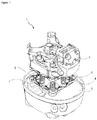
- A compressor realized in order to attain the aim of the present invention is illustrated in the attached figures, where:
-
Figure 1 - is the perspective view of the compressor. -
Figure 2 - is the perspective view of the brackets which are joined together. -
Figure 3 - is the perspective view of the bracket. - The elements illustrated in the figures are numbered as follows:
- 1. Compressor
- 2. Kit group
- 3. Lower casing
- 4. Spring
- 5. Bracket
- 6. Fixing hole
- 7. Spring housing
- The compressor (1) comprises a kit group (2), a lower casing (3) provided under the kit group (2), and at least one spring (4) arranged between the lower casing (3) and the kit group (2). The springs (4) are arranged between the lower casing (3) and the kit group (2). Generally, four springs (4) arranged on the corners of the lower casing (3) and the kit group (2) are used. By means of the springs (4), the vibrations generated in the kit group (2) are prevented from being transferred, and transferred to the lower casing (3) with at least partially reduced amplitudes. Thus, the strength of the compressor (1) is increased, and the noise and the vibrations are decreased.
- The compressor (1) of the present invention comprises at least one bracket (5) provided between the lower casing (3) and the spring (4), and between the kit group (2) and the spring (4). Since the suspension frequency of the springs (4) of the kit group (2) is decreased by means of the bracket (5) provided between the springs (4) and the lower casing (3) and between the springs (4) and the kit group (2), the risk of resonance is avoided. Thus, the amount of vibration transferred to the kit group (2) and the lower casing (3) is decreased. The springs (4) are prevented from resonating especially during vibrations at lower operational speeds. The noise is enabled to be decreased as the vibrations are decreased. The strength of the compressor (1) is improved.
- In an embodiment of the present invention, the compressor (1) comprises the bracket (5) having a fixing hole (6) provided at both ends thereof, and a spring housing (7) arranged between two fixing holes (6). The bracket (5) is fixed onto the lower casing (3) and the kit group (2) through the fixing holes (6). The spring housing (7) is provided almost in the middle of the two fixing holes (6). The spring (4) is placed onto the spring housing (7). Thus, spring (4) is enabled to maintain its position while moving.
- In an embodiment of the present invention, the compressor (1) comprises the bracket (5) which can be detachably attached to the lower casing (3) and the kit group (2). In an embodiment of the present invention, the bracket (5) can be detachably attached to the lower casing (3) and the kit group (2). Thus, the bracket (5) can be easily replaced when deformed.
- In an embodiment of the present invention, the compressor (1) comprises at least three brackets (5) which are connected to each other. The brackets (5) are connected to each other through the fixing hole (6). At least three brackets (5) can be used. As the number of springs (4) and the distance between the springs (4) decrease, the costs are reduced, and the risk of resonance decreases as the frequency decreases.
- In an embodiment of the present invention, the compressor (1) comprises the bracket (5) produced from a material which at least partially dampens vibrations. By producing the bracket (5) from a material which dampens vibrations, the vibrations transferred via the spring (4) are prevented from reaching the lower casing (3).
- In an embodiment of the present invention, the compressor (1) comprises the bracket (5) which is produced from plastic material. By producing the bracket (5) from plastic material, the cost is decreased. Furthermore, the dynamic strength is improved and the risk of deformation is decreased.
- In an embodiment of the present invention, the compressor (1) is suitable for use in cooling devices.
- By means of the present invention, a variable speed compressor (1) is realized, wherein brackets (5) preventing the springs (4) from resonating at lower vibration amplitudes are used. The vibrations on the springs (4) are decreased by means of the brackets (5) whereon the springs (4) are placed. Thereby, the efficiency and the economic life of the compressor (1) are increased.
Claims (7)
- A compressor (1) comprising a kit group (2), a lower casing (4) provided under the kit group (2) and at least one spring (4) arranged between the lower casing (3) and the kit group (2), characterized by at least one bracket (5) provided between the lower casing (3) and the spring (4), and between the kit group (2) and the spring (4).
- A compressor (1) as in Claim 1, characterized by the bracket (5) having a fixing (6) hole provided at both ends thereof and a spring housing (7) arranged between two fixing holes (6).
- A compressor (1) as in Claim 1 or Claim 2, characterized by the bracket (5) which can be detachably attached to the lower casing (3) and the kit group (2).
- A compressor (1) as in any one of the above claims, characterized by at least three brackets (5) which are connected to each other.
- A compressor (1) as in any one of the above claims, characterized by the bracket (5) which is produced from material which dampens the vibrations at least partially.
- A compressor (1) as in Claim 5, characterized by the bracket (5) which is produced from plastic material.
- A compressor (1) as in any one of the above claims, which is suitable to be used in cooling devices.
Applications Claiming Priority (1)
| Application Number | Priority Date | Filing Date | Title |
|---|---|---|---|
| TR201919277 | 2019-12-04 |
Publications (2)
| Publication Number | Publication Date |
|---|---|
| EP3832134A1 true EP3832134A1 (en) | 2021-06-09 |
| EP3832134B1 EP3832134B1 (en) | 2024-05-01 |
Family
ID=73642628
Family Applications (1)
| Application Number | Title | Priority Date | Filing Date |
|---|---|---|---|
| EP20210251.3A Active EP3832134B1 (en) | 2019-12-04 | 2020-11-27 | A variable speed compressor |
Country Status (2)
| Country | Link |
|---|---|
| EP (1) | EP3832134B1 (en) |
| PL (1) | PL3832134T3 (en) |
Citations (6)
| Publication number | Priority date | Publication date | Assignee | Title |
|---|---|---|---|---|
| GB540260A (en) | 1939-04-25 | 1941-10-10 | British Thomson Houston Co Ltd | Improvements in and relating to refrigerating machines |
| US2349845A (en) * | 1942-02-05 | 1944-05-30 | Westinghouse Electric & Mfg Co | Refrigerating apparatus |
| WO2004081379A2 (en) * | 2003-03-11 | 2004-09-23 | Lg Electronics Inc. | Reciprocating compressor having vibration attenuating supporting unit |
| DE112014005119T5 (en) * | 2013-11-07 | 2016-07-28 | Sanden Holdings Corporation | Mounting structure for an electric compressor |
| CN108843556A (en) * | 2018-06-28 | 2018-11-20 | 合肥信仁液压机械有限公司 | It is a kind of to facilitate fixed water pump |
| CN106224225B (en) * | 2016-08-24 | 2018-12-18 | 珠海格力电器股份有限公司 | Support structure for vertical pump |
Family Cites Families (3)
| Publication number | Priority date | Publication date | Assignee | Title |
|---|---|---|---|---|
| KR100524711B1 (en) * | 2003-04-07 | 2005-11-01 | 엘지전자 주식회사 | Reciprocating compressor |
| KR100807278B1 (en) * | 2006-12-18 | 2008-02-28 | 삼성전자주식회사 | Compressor fixture |
| KR102349748B1 (en) * | 2020-08-12 | 2022-01-11 | 엘지전자 주식회사 | Enclosed compressor |
-
2020
- 2020-11-27 EP EP20210251.3A patent/EP3832134B1/en active Active
- 2020-11-27 PL PL20210251.3T patent/PL3832134T3/en unknown
Patent Citations (6)
| Publication number | Priority date | Publication date | Assignee | Title |
|---|---|---|---|---|
| GB540260A (en) | 1939-04-25 | 1941-10-10 | British Thomson Houston Co Ltd | Improvements in and relating to refrigerating machines |
| US2349845A (en) * | 1942-02-05 | 1944-05-30 | Westinghouse Electric & Mfg Co | Refrigerating apparatus |
| WO2004081379A2 (en) * | 2003-03-11 | 2004-09-23 | Lg Electronics Inc. | Reciprocating compressor having vibration attenuating supporting unit |
| DE112014005119T5 (en) * | 2013-11-07 | 2016-07-28 | Sanden Holdings Corporation | Mounting structure for an electric compressor |
| CN106224225B (en) * | 2016-08-24 | 2018-12-18 | 珠海格力电器股份有限公司 | Support structure for vertical pump |
| CN108843556A (en) * | 2018-06-28 | 2018-11-20 | 合肥信仁液压机械有限公司 | It is a kind of to facilitate fixed water pump |
Also Published As
| Publication number | Publication date |
|---|---|
| EP3832134B1 (en) | 2024-05-01 |
| PL3832134T3 (en) | 2024-09-02 |
Similar Documents
| Publication | Publication Date | Title |
|---|---|---|
| US8397834B2 (en) | Oscillating tool with vibration damping system | |
| US6009986A (en) | Mass damper | |
| US20180149148A1 (en) | Refrigerant compressor | |
| US5342179A (en) | Compressor shock absorbing mount assembly | |
| CN109185151A (en) | Vibration reduction balance block, compressor and refrigeration equipment | |
| EP3203069B1 (en) | Hermetic compressor and refrigeration device | |
| JP5049938B2 (en) | Simplified dynamic vibration absorber and vibration control method | |
| JP2015135093A (en) | Electric compressor and method for manufacturing electric compressor | |
| EP3832134B1 (en) | A variable speed compressor | |
| JP3464446B2 (en) | Hermetic compressor | |
| US20070041855A1 (en) | Linear compressor, particularly refrigerant compressor | |
| JP2013104297A (en) | Steam turbine low-pressure casing | |
| JP2000240718A (en) | Vibration damping device for compressor | |
| CA2473913C (en) | Shaft damper | |
| CN105927707B (en) | A kind of Small electronic component double-layer damper based on flat spring | |
| CN217056104U (en) | Damping callus on sole and temperature control equipment | |
| AU2003212807A1 (en) | Shaft damper | |
| RU2507456C2 (en) | Refrigerating compressor | |
| KR20010087554A (en) | Noise/Vibration Falling Apparatus Of a Compressor | |
| US20140070469A1 (en) | Suspension spring for a refrigeration compressor | |
| CN118998055A (en) | Compressor assembly, air conditioner external unit and air conditioner | |
| CN109631173A (en) | Air-conditioner outdoor unit and air conditioner with it | |
| EP2466072A2 (en) | Axial air movement fans | |
| CN209278134U (en) | Vibration reduction balance block, compressor and refrigeration equipment | |
| JP7110829B2 (en) | dynamic damper |
Legal Events
| Date | Code | Title | Description |
|---|---|---|---|
| PUAI | Public reference made under article 153(3) epc to a published international application that has entered the european phase |
Free format text: ORIGINAL CODE: 0009012 |
|
| STAA | Information on the status of an ep patent application or granted ep patent |
Free format text: STATUS: REQUEST FOR EXAMINATION WAS MADE |
|
| 17P | Request for examination filed |
Effective date: 20201127 |
|
| AK | Designated contracting states |
Kind code of ref document: A1 Designated state(s): AL AT BE BG CH CY CZ DE DK EE ES FI FR GB GR HR HU IE IS IT LI LT LU LV MC MK MT NL NO PL PT RO RS SE SI SK SM TR |
|
| STAA | Information on the status of an ep patent application or granted ep patent |
Free format text: STATUS: EXAMINATION IS IN PROGRESS |
|
| 17Q | First examination report despatched |
Effective date: 20220622 |
|
| GRAP | Despatch of communication of intention to grant a patent |
Free format text: ORIGINAL CODE: EPIDOSNIGR1 |
|
| STAA | Information on the status of an ep patent application or granted ep patent |
Free format text: STATUS: GRANT OF PATENT IS INTENDED |
|
| INTG | Intention to grant announced |
Effective date: 20240206 |
|
| GRAS | Grant fee paid |
Free format text: ORIGINAL CODE: EPIDOSNIGR3 |
|
| GRAA | (expected) grant |
Free format text: ORIGINAL CODE: 0009210 |
|
| STAA | Information on the status of an ep patent application or granted ep patent |
Free format text: STATUS: THE PATENT HAS BEEN GRANTED |
|
| AK | Designated contracting states |
Kind code of ref document: B1 Designated state(s): AL AT BE BG CH CY CZ DE DK EE ES FI FR GB GR HR HU IE IS IT LI LT LU LV MC MK MT NL NO PL PT RO RS SE SI SK SM TR |
|
| REG | Reference to a national code |
Ref country code: GB Ref legal event code: FG4D |
|
| REG | Reference to a national code |
Ref country code: CH Ref legal event code: EP |
|
| REG | Reference to a national code |
Ref country code: DE Ref legal event code: R096 Ref document number: 602020030014 Country of ref document: DE |
|
| REG | Reference to a national code |
Ref country code: IE Ref legal event code: FG4D |
|
| REG | Reference to a national code |
Ref country code: LT Ref legal event code: MG9D |
|
| REG | Reference to a national code |
Ref country code: NL Ref legal event code: MP Effective date: 20240501 |
|
| PG25 | Lapsed in a contracting state [announced via postgrant information from national office to epo] |
Ref country code: IS Free format text: LAPSE BECAUSE OF FAILURE TO SUBMIT A TRANSLATION OF THE DESCRIPTION OR TO PAY THE FEE WITHIN THE PRESCRIBED TIME-LIMIT Effective date: 20240901 |
|
| PG25 | Lapsed in a contracting state [announced via postgrant information from national office to epo] |
Ref country code: BG Free format text: LAPSE BECAUSE OF FAILURE TO SUBMIT A TRANSLATION OF THE DESCRIPTION OR TO PAY THE FEE WITHIN THE PRESCRIBED TIME-LIMIT Effective date: 20240501 |
|
| PG25 | Lapsed in a contracting state [announced via postgrant information from national office to epo] |
Ref country code: HR Free format text: LAPSE BECAUSE OF FAILURE TO SUBMIT A TRANSLATION OF THE DESCRIPTION OR TO PAY THE FEE WITHIN THE PRESCRIBED TIME-LIMIT Effective date: 20240501 Ref country code: FI Free format text: LAPSE BECAUSE OF FAILURE TO SUBMIT A TRANSLATION OF THE DESCRIPTION OR TO PAY THE FEE WITHIN THE PRESCRIBED TIME-LIMIT Effective date: 20240501 |
|
| PG25 | Lapsed in a contracting state [announced via postgrant information from national office to epo] |
Ref country code: GR Free format text: LAPSE BECAUSE OF FAILURE TO SUBMIT A TRANSLATION OF THE DESCRIPTION OR TO PAY THE FEE WITHIN THE PRESCRIBED TIME-LIMIT Effective date: 20240802 |
|
| PG25 | Lapsed in a contracting state [announced via postgrant information from national office to epo] |
Ref country code: PT Free format text: LAPSE BECAUSE OF FAILURE TO SUBMIT A TRANSLATION OF THE DESCRIPTION OR TO PAY THE FEE WITHIN THE PRESCRIBED TIME-LIMIT Effective date: 20240902 |
|
| REG | Reference to a national code |
Ref country code: AT Ref legal event code: MK05 Ref document number: 1682669 Country of ref document: AT Kind code of ref document: T Effective date: 20240501 |
|
| PG25 | Lapsed in a contracting state [announced via postgrant information from national office to epo] |
Ref country code: NL Free format text: LAPSE BECAUSE OF FAILURE TO SUBMIT A TRANSLATION OF THE DESCRIPTION OR TO PAY THE FEE WITHIN THE PRESCRIBED TIME-LIMIT Effective date: 20240501 |
|
| PG25 | Lapsed in a contracting state [announced via postgrant information from national office to epo] |
Ref country code: ES Free format text: LAPSE BECAUSE OF FAILURE TO SUBMIT A TRANSLATION OF THE DESCRIPTION OR TO PAY THE FEE WITHIN THE PRESCRIBED TIME-LIMIT Effective date: 20240501 |
|
| PG25 | Lapsed in a contracting state [announced via postgrant information from national office to epo] |
Ref country code: AT Free format text: LAPSE BECAUSE OF FAILURE TO SUBMIT A TRANSLATION OF THE DESCRIPTION OR TO PAY THE FEE WITHIN THE PRESCRIBED TIME-LIMIT Effective date: 20240501 |
|
| PG25 | Lapsed in a contracting state [announced via postgrant information from national office to epo] |
Ref country code: LV Free format text: LAPSE BECAUSE OF FAILURE TO SUBMIT A TRANSLATION OF THE DESCRIPTION OR TO PAY THE FEE WITHIN THE PRESCRIBED TIME-LIMIT Effective date: 20240501 |
|
| PG25 | Lapsed in a contracting state [announced via postgrant information from national office to epo] |
Ref country code: PT Free format text: LAPSE BECAUSE OF FAILURE TO SUBMIT A TRANSLATION OF THE DESCRIPTION OR TO PAY THE FEE WITHIN THE PRESCRIBED TIME-LIMIT Effective date: 20240902 Ref country code: NO Free format text: LAPSE BECAUSE OF FAILURE TO SUBMIT A TRANSLATION OF THE DESCRIPTION OR TO PAY THE FEE WITHIN THE PRESCRIBED TIME-LIMIT Effective date: 20240801 Ref country code: NL Free format text: LAPSE BECAUSE OF FAILURE TO SUBMIT A TRANSLATION OF THE DESCRIPTION OR TO PAY THE FEE WITHIN THE PRESCRIBED TIME-LIMIT Effective date: 20240501 Ref country code: LV Free format text: LAPSE BECAUSE OF FAILURE TO SUBMIT A TRANSLATION OF THE DESCRIPTION OR TO PAY THE FEE WITHIN THE PRESCRIBED TIME-LIMIT Effective date: 20240501 Ref country code: IS Free format text: LAPSE BECAUSE OF FAILURE TO SUBMIT A TRANSLATION OF THE DESCRIPTION OR TO PAY THE FEE WITHIN THE PRESCRIBED TIME-LIMIT Effective date: 20240901 Ref country code: HR Free format text: LAPSE BECAUSE OF FAILURE TO SUBMIT A TRANSLATION OF THE DESCRIPTION OR TO PAY THE FEE WITHIN THE PRESCRIBED TIME-LIMIT Effective date: 20240501 Ref country code: GR Free format text: LAPSE BECAUSE OF FAILURE TO SUBMIT A TRANSLATION OF THE DESCRIPTION OR TO PAY THE FEE WITHIN THE PRESCRIBED TIME-LIMIT Effective date: 20240802 Ref country code: FI Free format text: LAPSE BECAUSE OF FAILURE TO SUBMIT A TRANSLATION OF THE DESCRIPTION OR TO PAY THE FEE WITHIN THE PRESCRIBED TIME-LIMIT Effective date: 20240501 Ref country code: ES Free format text: LAPSE BECAUSE OF FAILURE TO SUBMIT A TRANSLATION OF THE DESCRIPTION OR TO PAY THE FEE WITHIN THE PRESCRIBED TIME-LIMIT Effective date: 20240501 Ref country code: BG Free format text: LAPSE BECAUSE OF FAILURE TO SUBMIT A TRANSLATION OF THE DESCRIPTION OR TO PAY THE FEE WITHIN THE PRESCRIBED TIME-LIMIT Effective date: 20240501 Ref country code: AT Free format text: LAPSE BECAUSE OF FAILURE TO SUBMIT A TRANSLATION OF THE DESCRIPTION OR TO PAY THE FEE WITHIN THE PRESCRIBED TIME-LIMIT Effective date: 20240501 Ref country code: RS Free format text: LAPSE BECAUSE OF FAILURE TO SUBMIT A TRANSLATION OF THE DESCRIPTION OR TO PAY THE FEE WITHIN THE PRESCRIBED TIME-LIMIT Effective date: 20240801 |
|
| PG25 | Lapsed in a contracting state [announced via postgrant information from national office to epo] |
Ref country code: DK Free format text: LAPSE BECAUSE OF FAILURE TO SUBMIT A TRANSLATION OF THE DESCRIPTION OR TO PAY THE FEE WITHIN THE PRESCRIBED TIME-LIMIT Effective date: 20240501 |
|
| PG25 | Lapsed in a contracting state [announced via postgrant information from national office to epo] |
Ref country code: EE Free format text: LAPSE BECAUSE OF FAILURE TO SUBMIT A TRANSLATION OF THE DESCRIPTION OR TO PAY THE FEE WITHIN THE PRESCRIBED TIME-LIMIT Effective date: 20240501 |
|
| PG25 | Lapsed in a contracting state [announced via postgrant information from national office to epo] |
Ref country code: CZ Free format text: LAPSE BECAUSE OF FAILURE TO SUBMIT A TRANSLATION OF THE DESCRIPTION OR TO PAY THE FEE WITHIN THE PRESCRIBED TIME-LIMIT Effective date: 20240501 |
|
| PG25 | Lapsed in a contracting state [announced via postgrant information from national office to epo] |
Ref country code: RO Free format text: LAPSE BECAUSE OF FAILURE TO SUBMIT A TRANSLATION OF THE DESCRIPTION OR TO PAY THE FEE WITHIN THE PRESCRIBED TIME-LIMIT Effective date: 20240501 Ref country code: SK Free format text: LAPSE BECAUSE OF FAILURE TO SUBMIT A TRANSLATION OF THE DESCRIPTION OR TO PAY THE FEE WITHIN THE PRESCRIBED TIME-LIMIT Effective date: 20240501 |
|
| PG25 | Lapsed in a contracting state [announced via postgrant information from national office to epo] |
Ref country code: SM Free format text: LAPSE BECAUSE OF FAILURE TO SUBMIT A TRANSLATION OF THE DESCRIPTION OR TO PAY THE FEE WITHIN THE PRESCRIBED TIME-LIMIT Effective date: 20240501 |
|
| PG25 | Lapsed in a contracting state [announced via postgrant information from national office to epo] |
Ref country code: SM Free format text: LAPSE BECAUSE OF FAILURE TO SUBMIT A TRANSLATION OF THE DESCRIPTION OR TO PAY THE FEE WITHIN THE PRESCRIBED TIME-LIMIT Effective date: 20240501 Ref country code: SK Free format text: LAPSE BECAUSE OF FAILURE TO SUBMIT A TRANSLATION OF THE DESCRIPTION OR TO PAY THE FEE WITHIN THE PRESCRIBED TIME-LIMIT Effective date: 20240501 Ref country code: RO Free format text: LAPSE BECAUSE OF FAILURE TO SUBMIT A TRANSLATION OF THE DESCRIPTION OR TO PAY THE FEE WITHIN THE PRESCRIBED TIME-LIMIT Effective date: 20240501 Ref country code: EE Free format text: LAPSE BECAUSE OF FAILURE TO SUBMIT A TRANSLATION OF THE DESCRIPTION OR TO PAY THE FEE WITHIN THE PRESCRIBED TIME-LIMIT Effective date: 20240501 Ref country code: DK Free format text: LAPSE BECAUSE OF FAILURE TO SUBMIT A TRANSLATION OF THE DESCRIPTION OR TO PAY THE FEE WITHIN THE PRESCRIBED TIME-LIMIT Effective date: 20240501 Ref country code: CZ Free format text: LAPSE BECAUSE OF FAILURE TO SUBMIT A TRANSLATION OF THE DESCRIPTION OR TO PAY THE FEE WITHIN THE PRESCRIBED TIME-LIMIT Effective date: 20240501 |
|
| REG | Reference to a national code |
Ref country code: DE Ref legal event code: R097 Ref document number: 602020030014 Country of ref document: DE |
|
| PG25 | Lapsed in a contracting state [announced via postgrant information from national office to epo] |
Ref country code: IT Free format text: LAPSE BECAUSE OF FAILURE TO SUBMIT A TRANSLATION OF THE DESCRIPTION OR TO PAY THE FEE WITHIN THE PRESCRIBED TIME-LIMIT Effective date: 20240501 |
|
| PLBE | No opposition filed within time limit |
Free format text: ORIGINAL CODE: 0009261 |
|
| STAA | Information on the status of an ep patent application or granted ep patent |
Free format text: STATUS: NO OPPOSITION FILED WITHIN TIME LIMIT |
|
| 26N | No opposition filed |
Effective date: 20250204 |
|
| PG25 | Lapsed in a contracting state [announced via postgrant information from national office to epo] |
Ref country code: SI Free format text: LAPSE BECAUSE OF FAILURE TO SUBMIT A TRANSLATION OF THE DESCRIPTION OR TO PAY THE FEE WITHIN THE PRESCRIBED TIME-LIMIT Effective date: 20240501 |
|
| REG | Reference to a national code |
Ref country code: DE Ref legal event code: R119 Ref document number: 602020030014 Country of ref document: DE |
|
| REG | Reference to a national code |
Ref country code: CH Ref legal event code: PL |
|
| PG25 | Lapsed in a contracting state [announced via postgrant information from national office to epo] |
Ref country code: MC Free format text: LAPSE BECAUSE OF FAILURE TO SUBMIT A TRANSLATION OF THE DESCRIPTION OR TO PAY THE FEE WITHIN THE PRESCRIBED TIME-LIMIT Effective date: 20240501 |
|
| PG25 | Lapsed in a contracting state [announced via postgrant information from national office to epo] |
Ref country code: LU Free format text: LAPSE BECAUSE OF NON-PAYMENT OF DUE FEES Effective date: 20241127 |
|
| REG | Reference to a national code |
Ref country code: CH Ref legal event code: PL |
|
| PG25 | Lapsed in a contracting state [announced via postgrant information from national office to epo] |
Ref country code: CH Free format text: LAPSE BECAUSE OF NON-PAYMENT OF DUE FEES Effective date: 20241130 |
|
| REG | Reference to a national code |
Ref country code: BE Ref legal event code: MM Effective date: 20241130 |
|
| PG25 | Lapsed in a contracting state [announced via postgrant information from national office to epo] |
Ref country code: SE Free format text: LAPSE BECAUSE OF FAILURE TO SUBMIT A TRANSLATION OF THE DESCRIPTION OR TO PAY THE FEE WITHIN THE PRESCRIBED TIME-LIMIT Effective date: 20240501 |
|
| PG25 | Lapsed in a contracting state [announced via postgrant information from national office to epo] |
Ref country code: DE Free format text: LAPSE BECAUSE OF NON-PAYMENT OF DUE FEES Effective date: 20250603 |
|
| PG25 | Lapsed in a contracting state [announced via postgrant information from national office to epo] |
Ref country code: BE Free format text: LAPSE BECAUSE OF NON-PAYMENT OF DUE FEES Effective date: 20241130 |
|
| PG25 | Lapsed in a contracting state [announced via postgrant information from national office to epo] |
Ref country code: FR Free format text: LAPSE BECAUSE OF NON-PAYMENT OF DUE FEES Effective date: 20241130 |
|
| PG25 | Lapsed in a contracting state [announced via postgrant information from national office to epo] |
Ref country code: IE Free format text: LAPSE BECAUSE OF NON-PAYMENT OF DUE FEES Effective date: 20241127 |
|
| PGFP | Annual fee paid to national office [announced via postgrant information from national office to epo] |
Ref country code: GB Payment date: 20251121 Year of fee payment: 6 |
|
| PGFP | Annual fee paid to national office [announced via postgrant information from national office to epo] |
Ref country code: TR Payment date: 20251111 Year of fee payment: 6 |
|
| PGFP | Annual fee paid to national office [announced via postgrant information from national office to epo] |
Ref country code: PL Payment date: 20251114 Year of fee payment: 6 |
|
| PG25 | Lapsed in a contracting state [announced via postgrant information from national office to epo] |
Ref country code: HU Free format text: LAPSE BECAUSE OF FAILURE TO SUBMIT A TRANSLATION OF THE DESCRIPTION OR TO PAY THE FEE WITHIN THE PRESCRIBED TIME-LIMIT; INVALID AB INITIO Effective date: 20201127 |
|
| PG25 | Lapsed in a contracting state [announced via postgrant information from national office to epo] |
Ref country code: CY Free format text: LAPSE BECAUSE OF FAILURE TO SUBMIT A TRANSLATION OF THE DESCRIPTION OR TO PAY THE FEE WITHIN THE PRESCRIBED TIME-LIMIT; INVALID AB INITIO Effective date: 20201127 |
|
| PG25 | Lapsed in a contracting state [announced via postgrant information from national office to epo] |
Ref country code: LT Free format text: LAPSE BECAUSE OF FAILURE TO SUBMIT A TRANSLATION OF THE DESCRIPTION OR TO PAY THE FEE WITHIN THE PRESCRIBED TIME-LIMIT Effective date: 20240501 |