EP3832116B1 - Control device for compression self-ignition engine, compression self-ignition engine, method of controlling engine, and computer program product - Google Patents
Control device for compression self-ignition engine, compression self-ignition engine, method of controlling engine, and computer program product Download PDFInfo
- Publication number
- EP3832116B1 EP3832116B1 EP20209690.5A EP20209690A EP3832116B1 EP 3832116 B1 EP3832116 B1 EP 3832116B1 EP 20209690 A EP20209690 A EP 20209690A EP 3832116 B1 EP3832116 B1 EP 3832116B1
- Authority
- EP
- European Patent Office
- Prior art keywords
- timing
- injection
- combustion
- compression
- fuel
- Prior art date
- Legal status (The legal status is an assumption and is not a legal conclusion. Google has not performed a legal analysis and makes no representation as to the accuracy of the status listed.)
- Active
Links
- 238000007906 compression Methods 0.000 title claims description 72
- 230000006835 compression Effects 0.000 title claims description 71
- 238000000034 method Methods 0.000 title claims description 10
- 238000004590 computer program Methods 0.000 title claims description 4
- 238000002347 injection Methods 0.000 claims description 286
- 239000007924 injection Substances 0.000 claims description 286
- 238000002485 combustion reaction Methods 0.000 claims description 197
- 239000000446 fuel Substances 0.000 claims description 126
- 239000000203 mixture Substances 0.000 claims description 53
- 230000007246 mechanism Effects 0.000 description 15
- XLYOFNOQVPJJNP-UHFFFAOYSA-N water Substances O XLYOFNOQVPJJNP-UHFFFAOYSA-N 0.000 description 9
- 239000000284 extract Substances 0.000 description 6
- 239000004071 soot Substances 0.000 description 6
- 230000005484 gravity Effects 0.000 description 5
- 230000000979 retarding effect Effects 0.000 description 5
- 230000007423 decrease Effects 0.000 description 4
- 239000007921 spray Substances 0.000 description 4
- 238000002156 mixing Methods 0.000 description 3
- 238000004364 calculation method Methods 0.000 description 2
- 230000003197 catalytic effect Effects 0.000 description 2
- 239000002826 coolant Substances 0.000 description 2
- 238000010586 diagram Methods 0.000 description 2
- 230000000694 effects Effects 0.000 description 2
- 238000011144 upstream manufacturing Methods 0.000 description 2
- 238000009834 vaporization Methods 0.000 description 2
- 230000008016 vaporization Effects 0.000 description 2
- 238000013459 approach Methods 0.000 description 1
- 239000003054 catalyst Substances 0.000 description 1
- 238000001816 cooling Methods 0.000 description 1
- 238000009792 diffusion process Methods 0.000 description 1
- 238000007599 discharging Methods 0.000 description 1
- 238000012986 modification Methods 0.000 description 1
- 230000004048 modification Effects 0.000 description 1
- 230000005855 radiation Effects 0.000 description 1
- 230000000630 rising effect Effects 0.000 description 1
Images


Classifications
-
- F—MECHANICAL ENGINEERING; LIGHTING; HEATING; WEAPONS; BLASTING
- F02—COMBUSTION ENGINES; HOT-GAS OR COMBUSTION-PRODUCT ENGINE PLANTS
- F02D—CONTROLLING COMBUSTION ENGINES
- F02D41/00—Electrical control of supply of combustible mixture or its constituents
- F02D41/30—Controlling fuel injection
- F02D41/38—Controlling fuel injection of the high pressure type
- F02D41/40—Controlling fuel injection of the high pressure type with means for controlling injection timing or duration
- F02D41/402—Multiple injections
-
- F—MECHANICAL ENGINEERING; LIGHTING; HEATING; WEAPONS; BLASTING
- F02—COMBUSTION ENGINES; HOT-GAS OR COMBUSTION-PRODUCT ENGINE PLANTS
- F02D—CONTROLLING COMBUSTION ENGINES
- F02D41/00—Electrical control of supply of combustible mixture or its constituents
- F02D41/30—Controlling fuel injection
- F02D41/3011—Controlling fuel injection according to or using specific or several modes of combustion
- F02D41/3017—Controlling fuel injection according to or using specific or several modes of combustion characterised by the mode(s) being used
- F02D41/3035—Controlling fuel injection according to or using specific or several modes of combustion characterised by the mode(s) being used a mode being the premixed charge compression-ignition mode
-
- F—MECHANICAL ENGINEERING; LIGHTING; HEATING; WEAPONS; BLASTING
- F02—COMBUSTION ENGINES; HOT-GAS OR COMBUSTION-PRODUCT ENGINE PLANTS
- F02D—CONTROLLING COMBUSTION ENGINES
- F02D35/00—Controlling engines, dependent on conditions exterior or interior to engines, not otherwise provided for
- F02D35/02—Controlling engines, dependent on conditions exterior or interior to engines, not otherwise provided for on interior conditions
- F02D35/025—Controlling engines, dependent on conditions exterior or interior to engines, not otherwise provided for on interior conditions by determining temperatures inside the cylinder, e.g. combustion temperatures
- F02D35/026—Controlling engines, dependent on conditions exterior or interior to engines, not otherwise provided for on interior conditions by determining temperatures inside the cylinder, e.g. combustion temperatures using an estimation
-
- F—MECHANICAL ENGINEERING; LIGHTING; HEATING; WEAPONS; BLASTING
- F02—COMBUSTION ENGINES; HOT-GAS OR COMBUSTION-PRODUCT ENGINE PLANTS
- F02D—CONTROLLING COMBUSTION ENGINES
- F02D35/00—Controlling engines, dependent on conditions exterior or interior to engines, not otherwise provided for
- F02D35/02—Controlling engines, dependent on conditions exterior or interior to engines, not otherwise provided for on interior conditions
- F02D35/028—Controlling engines, dependent on conditions exterior or interior to engines, not otherwise provided for on interior conditions by determining the combustion timing or phasing
-
- F—MECHANICAL ENGINEERING; LIGHTING; HEATING; WEAPONS; BLASTING
- F02—COMBUSTION ENGINES; HOT-GAS OR COMBUSTION-PRODUCT ENGINE PLANTS
- F02D—CONTROLLING COMBUSTION ENGINES
- F02D41/00—Electrical control of supply of combustible mixture or its constituents
- F02D41/30—Controlling fuel injection
- F02D41/3011—Controlling fuel injection according to or using specific or several modes of combustion
- F02D41/3017—Controlling fuel injection according to or using specific or several modes of combustion characterised by the mode(s) being used
-
- F—MECHANICAL ENGINEERING; LIGHTING; HEATING; WEAPONS; BLASTING
- F02—COMBUSTION ENGINES; HOT-GAS OR COMBUSTION-PRODUCT ENGINE PLANTS
- F02D—CONTROLLING COMBUSTION ENGINES
- F02D41/00—Electrical control of supply of combustible mixture or its constituents
- F02D41/30—Controlling fuel injection
- F02D41/38—Controlling fuel injection of the high pressure type
- F02D41/40—Controlling fuel injection of the high pressure type with means for controlling injection timing or duration
- F02D41/401—Controlling injection timing
-
- F—MECHANICAL ENGINEERING; LIGHTING; HEATING; WEAPONS; BLASTING
- F02—COMBUSTION ENGINES; HOT-GAS OR COMBUSTION-PRODUCT ENGINE PLANTS
- F02D—CONTROLLING COMBUSTION ENGINES
- F02D2200/00—Input parameters for engine control
- F02D2200/02—Input parameters for engine control the parameters being related to the engine
- F02D2200/021—Engine temperature
- F02D2200/022—Estimation of engine temperature
-
- Y—GENERAL TAGGING OF NEW TECHNOLOGICAL DEVELOPMENTS; GENERAL TAGGING OF CROSS-SECTIONAL TECHNOLOGIES SPANNING OVER SEVERAL SECTIONS OF THE IPC; TECHNICAL SUBJECTS COVERED BY FORMER USPC CROSS-REFERENCE ART COLLECTIONS [XRACs] AND DIGESTS
- Y02—TECHNOLOGIES OR APPLICATIONS FOR MITIGATION OR ADAPTATION AGAINST CLIMATE CHANGE
- Y02T—CLIMATE CHANGE MITIGATION TECHNOLOGIES RELATED TO TRANSPORTATION
- Y02T10/00—Road transport of goods or passengers
- Y02T10/10—Internal combustion engine [ICE] based vehicles
- Y02T10/40—Engine management systems
Definitions
- the present disclosure relates to a control device for a compression self-ignition engine which includes a combustion chamber defined by a cylinder and a piston fitted in the cylinder, and an intake valve which opens and/or closes an intake port to introduce intake air into the combustion chamber.
- Compression self-ignition (CI) combustion in which a mixture gas of fuel and air combusts by self-ignition inside the combustion chamber is performed at least in a part of an operating range of the engine.
- the present disclosure also relates to a compression self-ignition engine, a method of controlling a compression self-ignition engine, and a computer program product.
- compression self-ignition combustion is a combustion mode in which the mixture gas formed inside a combustion chamber (inside a cylinder) is compressed by a piston so that the mixture gas becomes high in temperature and pressure to combust by self-ignition, not by the jump-spark ignition.
- the compression self-ignition combustion is believed to provide higher thermal efficiency, because concurrent self-ignition of the mixture gas at multiple locations of the combustion chamber reduces the combustion duration as compared to the combustion by the jump-spark ignition.
- the compression self-ignition combustion has the problem of a tendency of increasing combustion noise, because the self-ignition of the mixture gas in various areas causes a rapid increase in the in-cylinder pressure.
- JP2012-241589A discloses an engine in which fuel is injected into a combustion chamber at two separate timings (split injection) during a compression stroke and the mixture gas is caused to combust by self-ignition.
- a first fuel injection injects fuel to a radially-outward part of the combustion chamber
- a second fuel injection injects fuel into a cavity formed in a crown surface of a piston. This engine seeks to disperse the fuel inside the combustion chamber to avoid a concurrent start of combustion of all the fuel, thereby preventing the increase in combustion noise.
- JP2012-241589A may not fully reduce the combustion noise.
- the fuel is injected into the cavity at a timing near a compression top dead center, even when the combustion chamber is under a condition where the mixture gas is easily combustible. That is, in the condition of the combustion chamber where the mixture is already easy to combust, the fuel is further injected into the hot cavity.
- a rich mixture gas (with a high fuel ratio) formed in the cavity rapidly combusts, and this combustion causes a sudden increase in the temperature inside the combustion chamber, which further causes the mixture gas around the cavity to combust early. As a result, the in-cylinder pressure may rise rapidly.
- US 2017/211499 A1 describes an internal combustion engine comprising the fuel injector arranged in the combustion chamber.
- the primary fuel injection and the secondary fuel injection from the fuel injector are successively performed to cause autoignition of an injected fuel of the primary fuel injection and autoignition of an injected fuel of the secondary fuel injection.
- US 2006/243241 A1 relates to methods for robust controlled auto-ignition and spark ignited combustion controls in gasoline direct-injection engines, including transients, using either exhaust re-breathing or a combination of exhaust re-compression and re-breathing valve strategy.
- the present disclosure is made in view of the above situations, and one purpose thereof is to perform compression self-ignition combustion while reliably reducing an increase in combustion noise.
- the invention is a control device for a compression self-ignition engine as defined in claim 1 or a method as defined in claim 12.
- the first injection is carried out in which the fuel is injected at the first timing at which the fuel goes toward the part radially outward of the cavity.
- the temperature at the radially-outward part of the combustion chamber which is the part where the temperature becomes low easier than the center part of the combustion chamber, is further lowered by the latent heat of vaporization of the fuel in the first injection.
- the temperature inside the combustion chamber is unevenly distributed, which prevents that all the mixture gas inside the combustion chamber combusts concurrently.
- the second injection in which the fuel is injected at the second timing at which the fuel goes toward the cavity is suspended.
- a rich mixture gas is formed in the cavity at high temperature, and this rich mixture gas and the mixture gas inside the combustion chamber rapidly combust.
- the pressure inside the combustion chamber is prevented from rising rapidly and the increase in combustion noise can be reduced.
- the second injection is carried out and the rich mixture gas is formed inside the cavity at the comparatively high temperature at the timing nearer to the compression top dead center.
- this rich mixture gas and the mixture gas inside the combustion chamber can surely carry out self-ignition.
- the injection controller may determine a ratio of a first injection amount that is an amount of fuel injected at the first timing and a ratio of a second injection amount that is an amount of fuel injected at the second timing based on an intake valve close timing (IVC) estimated in-cylinder temperature that is the estimated temperature inside the combustion chamber.
- IVC intake valve close timing
- the ratios of the first injection amount and the second injection amount are determined according to the temperature of the combustion chamber at the close timing of the intake valve (i.e., according to the combustibility of the mixture gas), the combustion is prevented from occurring excessively early or excessively late, and thus, the proper compression self-ignition combustion (CI combustion) can be carried out more securely.
- the injection controller may determine the first timing and the second timing based on the IVC estimated in-cylinder temperature.
- the first injection and the second injection are carried out at suitable timings according to the temperature of the combustion chamber at the close timing of the intake valve (i.e., according to the combustibility of the mixture gas) and, thus, the proper compression self-ignition combustion (CI combustion) can be carried out furthermore securely.
- the injection controller may estimate a combustion center-of-gravity timing based on the IVC estimated in-cylinder temperature so that the combustion center-of-gravity timing becomes earlier as the IVC estimated in-cylinder temperature increases.
- the injection controller may determine the first injection amount and the second injection amount so that the ratio of the second injection amount to the sum of the first injection amount and the second injection amount becomes larger as the estimated combustion center-of-gravity timing is later.
- the injection controller may determine the first timing so that the first timing becomes earlier as the estimated combustion center-of-gravity timing is later, and/or determine the second timing so that the second timing becomes later as the estimated combustion center-of-gravity timing is later.
- the combustion center-of-gravity timing is estimated based on the IVC estimated in-cylinder temperature so that the combustion center-of-gravity timing becomes earlier as the IVC estimated in-cylinder temperature increases.
- the combustion center-of-gravity timing is estimated properly.
- the combustion center-of-gravity timing can be set more suitably and the more proper compression self-ignition combustion can be carried out.
- the present inventors obtained the knowledge that the combustion center-of-gravity timing becomes earlier as the ratio of the second injection amount to the sum of the first injection amount and the second injection amount is larger, the knowledge that the combustion center-of-gravity timing becomes later as the first timing is later, and the knowledge that the combustion center-of-gravity timing becomes later as the second timing is earlier. Accordingly, in this configuration, the ratio described above and the first and second timings are determined based on the estimated combustion center-of-gravity timing as described above, therefore, the combustion center-of-gravity timing can suitably be set more securely.
- the injection controller may cause the fuel injection system to carry out an intake-stroke injection to inject fuel in an intake stroke, particularly in addition to the first injection and/or the second injection.
- a compression self-ignition engine includes the above control device.
- a computer program product includes computer-readable instructions which, when loaded and executed on the above control device, perform the above method.
- Fig. 1 is a view illustrating the overall configuration of a compression self-ignition engine to which a control device for the compression self-ignition engine according to one embodiment of the present disclosure is applied.
- the compression self-ignition engine is simply referred to as the "engine.”
- the engine illustrated in this figure is a four-cycle engine mounted on a vehicle as a power source for propelling the vehicle (e.g., an automobile).
- the engine includes an engine body 1, an intake passage 28 where intake air introduced into the engine body 1 circulates, and an exhaust passage 29 where exhaust gas discharged from the engine body 1 circulates.
- the engine body 1 includes a cylinder block 3 where the cylinder 2 is formed therein, a cylinder head 4 attached to an upper surface of the cylinder block 3 to cover the cylinder 2 from above, and a piston 5 reciprocatably fitted in the cylinder 2.
- the engine body 1 is typically a multiple cylinder type having a plurality of cylinders (e.g., four cylinders line up in a direction perpendicular to the drawing sheet of Fig. 1 ), only one cylinder 2 is described herein for simplifying the description.
- a combustion chamber 6 is defined by the piston 5 and the cylinder 2.
- Fuel is supplied to the combustion chamber 6 by an injection from an injector 21 (described later).
- the supplied fuel is mixed with air and combusts inside the combustion chamber 6, and an expansion force caused by the combustion depresses the piston 5, thereby the piston 5 reciprocating in the up-and-down direction.
- a crankshaft 7 which is an output shaft of the engine body 1 is provided below the piston 5, a crankshaft 7 which is an output shaft of the engine body 1 is provided below the piston 5, a crankshaft 7 which is an output shaft of the engine body 1 is provided.
- the crankshaft 7 is coupled to the piston 5 via a connecting rod 8, and it is rotated on the center axis by the reciprocating motion (vertical motion) of the piston 5.
- the engine is a gasoline engine which mainly uses gasoline as fuel, and fuel which contains only gasoline, or contains a secondary component, such as bioethanol, in addition to gasoline, is supplied to the engine body 1.
- a concave cavity 40 is formed in a center part of a crown surface 5a of the piston 5.
- the cavity 40 is dented downwardly (the opposite side from the cylinder head 4).
- a bottom surface of the cavity 40 is formed in a gentle mountain shape, and has a peak part in a radial center part of the crown surface 5a of the piston 5 and the cavity 40.
- An inner circumferential part of the bottom surface of the cavity 40 is formed so that its height is gradually lowered to the radially outside from the radially-central peak part, and the height is again gradually raised to the radially outside in a radially-outward part.
- An intake port 9 for supplying intake air to the combustion chamber 6 and an exhaust port 10 for discharging exhaust gas inside the combustion chamber 6 are formed in the cylinder head 4.
- the intake port 9 and the exhaust port 10 open to the combustion chamber 6.
- the cylinder head 4 is provided with an intake valve 11 which opens and closes the intake port 9, and an exhaust valve 12 which opens and closes the exhaust port 10.
- the valve type of the engine of this embodiment is 4-valve type comprised of two intake valves and two exhaust valves, where two intake ports 9, two exhaust ports 10, two intake valves 11, and two exhaust valves 12 are provided to each cylinder 2.
- valve operating mechanisms 13 and 14 which includes a pair of cam shafts disposed inside the cylinder head 4 and opens and closes the valves 11 and 12, respectively.
- An intake-valve variable mechanism 15 which can change at least an open timing of the intake valve 11 is built in the valve operating mechanism 13 for the intake valve 11.
- an exhaust-valve variable mechanism 16 which can change at least a close timing of the exhaust valve 12 is built in the valve operating mechanism 14 for the exhaust valve 12.
- the intake-valve variable mechanism 15 (or the exhaust-valve variable mechanism 16) may be a variable mechanism which changes only the close timing (or the open timing) while the open timing (or the close timing) of the intake valve 11 (or the exhaust valve 12) is fixed, or may be a phase-type variable mechanism which simultaneously changes the open timing and the close timing of the intake valve 11 (or the exhaust valve 12).
- the cylinder head 4 is provided with a set of the injector 21 which injects fuel (mainly gasoline) into the combustion chamber 6, and an ignition plug 20 which ignites a mixture gas of fuel injected into the combustion chamber 6 from the injector 21 and air introduced into the combustion chamber 6, per cylinder 2.
- fuel mainly gasoline
- ignition plug 20 which ignites a mixture gas of fuel injected into the combustion chamber 6 from the injector 21 and air introduced into the combustion chamber 6, per cylinder 2.
- the injector 21 is a multiple nozzle hole type which has a plurality of nozzle holes at a tip-end part thereof.
- the injector 21 is provided to a center part of a ceiling surface 6a (a lower surface of the cylinder head 4 which covers the combustion chamber 6) of the combustion chamber 6 so that its tip-end part opposes to the part which constitutes the peak part described above of the center part of the crown surface 5a of the piston 5 and of the center part of the cavity 40. Fuel is injected radially from the nozzle holes of the injector 21.
- each nozzle hole of the injector 21 is formed so that its opening end is oriented obliquely downward, and outward in the bore radial direction, and therefore, the fuel injected from each nozzle hole is radially injected so that it spreads outside in the bore radial direction as it approaches the crown surface 5a of the piston 5.
- the injector 21 is connected to a fuel feed pipe 23, and fuel supplied through the fuel feed pipe 23 is injected from the tip-end part of the injector 21.
- This injector 21 is an example of a "fuel injection system" in the present disclosure.
- the ignition plug 20 is provided at a position deviated slightly from the injector 21 so that it faces the inside of the combustion chamber 6 from the ceiling surface 6a of the combustion chamber 6.
- the intake passage 28 is connected to one side surface of the cylinder head 4 so as to communicate with the intake port 9. Air (fresh air) taken in from an upstream end of the intake passage 28 is introduced into the combustion chamber 6 through the intake passage 28 and the intake port 9.
- the intake passage 28 is provided with a throttle valve 25 and a surge tank 28b, sequentially in this order from upstream.
- the throttle valve 25 opens and closes the intake passage 28 to adjust an amount of air which passes through the intake passage 28.
- the exhaust passage 29 is connected to the other side surface of the cylinder head 4 so as to communicate with the exhaust port 10. Burnt gas (exhaust gas) generated in the combustion chamber 6 is discharged outside through the exhaust port 10 and the exhaust passage 29.
- the exhaust passage 29 is provided with a catalytic converter 35 which purifies exhaust gas.
- a three-way catalyst is built in the catalytic converter 35.
- the cylinder block 3 is provided with a crank angle sensor SN1 which detects a rotational angle of the crankshaft 7 (i.e., an engine speed).
- a water jacket (not illustrated) where coolant circulates is formed inside the cylinder block 3 and the cylinder head 4 of the engine body 1, and the cylinder block 3 is also provided with a water temperature sensor SN2 which detects a temperature of the coolant inside the water jacket.
- An air flow sensor SN3 which detects an intake air amount which is an amount of air introduced into the cylinder 2, and an intake pressure sensor SN5 which detects an intake pressure which is a pressure of the air introduced into the cylinder 2 are disposed in the intake passage 28.
- the air flow sensor SN3 is disposed downstream of an air cleaner, and it detects a flow rate of air passing through this part.
- the intake pressure sensor SN5 is disposed at the surge tank 28b, and it detects a pressure of intake air passing through the surge tank 28b.
- Fig. 2 is a block diagram illustrating a control system of the engine.
- An electronic control unit (ECU) 100 illustrated in this figure is a control device comprised of a microcomputer for comprehensively controlling the engine, and is comprised of a processor (e.g., central processing unit (CPU)), ROM, RAM, etc., which are well known.
- the ECU 100 is configured to control the injector 21 as will be described later, and it is an example of an "injection controller" in the present disclosure.
- Detected information by the various sensors are inputted into the ECU 100.
- the ECU 100 is electrically connected to the crank angle sensor SN1, the water temperature sensor SN2, the air flow sensor SN3, an intake air temperature sensor SN4, and the intake pressure sensor SN5.
- the information detected by these sensors SN1 to SN5 i.e., the information, such as the engine speed, the engine water temperature, the intake air amount, the intake air temperature, and the intake pressure
- an accelerator opening sensor SN6 is provided to the vehicle, which detects an accelerator opening which is an opening of an accelerator pedal operated by a driver operating the vehicle. The detected information by the accelerator opening sensor SN6 is also sequentially inputted into the ECU 100.
- the ECU 100 controls each part of the engine, while performing various determinations and calculations based on the information inputted from the sensors SN1 to SN6. That is, the ECU 100 is electrically connected with the injector 21, the ignition plug 20, the throttle valve 25, the intake valve 11 (the intake-side valve operating mechanism 13), and the exhaust valve 12 (the exhaust-side valve operating mechanism 14), and outputs control signals to these components based on the results of the determinations and calculations.
- Fig. 3 is a map illustrating a difference in the control according to the engine speed and the engine load. As illustrated in this figure, an operating range of the engine is roughly divided into two sub ranges (i.e., a first range A1 and a second range A2). The second range A2 may not necessarily be essential.
- the first range A1 is a low-speed low-load range where the engine speed is a given switching engine speed N1 or lower and the engine load is a given switching load Tq1 or lower.
- the second range A2 is the remaining range other than the first range A1. Note that the switching load Tq1 is set so as to become lower as the engine speed increases.
- the first range A1 may include the remaining range other than the low-speed low-load range.
- the content of the control executed by the ECU 100 in the first range A1 is described.
- CI compression Ignition
- the mixture gas of fuel and air combusts inside the combustion chamber 6 by self-ignition is performed. That is, the mixture gas combusts only by a compression of the piston 5, without igniting the fuel by the ignition plug 20.
- the ignition plug 20 is stopped in the first range A1. In other words, in the first range A1, only CI combustion is performed.
- Fig. 4 is a view illustrating a fuel injection timing (a timing at which fuel is injected from the injector 21), lift characteristics of the intake valve 11 and the exhaust valve 12, and a heat release rate (J/deg) to be generated, when the engine is operated at a representative operating point in the first range A1. All of the features as shown in Fig. 4 may not necessarily essential.
- the exhaust valve 12 is opened also during an intake stroke, and exhaust gas once discharged to the exhaust port 10 from the combustion chamber 6 is again introduced back into the combustion chamber 6. That is, in the first range A1, internal EGR in which burnt gas remains inside the combustion chamber 6 is carried out.
- EGR internal EGR in which burnt gas remains inside the combustion chamber 6 is carried out.
- a close timing of the exhaust valve 12 (EVC) is retarded from an exhaust top dead center so that the exhaust valve 12 is opened across the exhaust top dead center.
- the opening and closing operation of the exhaust valve 12 is not limited to the operation as described above and/or as disclosed in Fig. 4 , and may not necessarily be essential for the CI combustion.
- the opening and closing operation of the exhaust valve 12 for carrying out the internal EGR may be, but not limited to be, one in which the exhaust valve 12 is opened twice by being opened again in an intake stroke after the exhaust valve 12 is closed once near an exhaust top dead center.
- the close timing of the exhaust valve 12 EMC
- IVO intake valve 11
- an intake-stroke injection F1 in which fuel is injected into the combustion chamber 6 from the injector 21 in an intake stroke, and/or a compression-stroke injection in which fuel is injected in a compression stroke are carried out.
- the fuel injection is only performed once during the compression stroke, but in the first range A1, a fuel injection F3 illustrated by a broken line may further be performed during the compression stroke.
- the injector 21 is possible to inject fuel dividedly twice in the compression stroke.
- Operation timing (start timing) of the intake-stroke injection F1 is in the first half of an intake stroke, for example, 60°CA (CA: crank angle) after an exhaust top dead center (i.e., about -300°CA before a compression top dead center).
- CA crank angle
- a first timing t_F2 which is an operation timing (start timing) of the first compression-stroke injection F2 is set at a timing when fuel injected by the first compression-stroke injection F2 from the injector 21 goes toward the part radially outward of the cavity 40. That is, the first timing t_F2 is set so that, as illustrated in Fig. 5 , a line X1 along an axis of a fuel spray Fm of fuel injected from the injector 21 passes through the part radially outward of the cavity 40.
- the operation timing of the first compression-stroke injection F2 is set at a timing of 1 80°CA to 90°CA before a compression top dead center.
- the first compression-stroke injection F2 is an example of a "first injection" in the present disclosure.
- a second timing t_F3 which is the operation timing (start timing) of the second compression-stroke injection F3 is set at a timing when fuel injected by the second compression-stroke injection F3 from the injector 21 goes toward the cavity 40 in the piston 5. That is, the second timing t_F3 is set so that, as illustrated in Fig. 6 , the line X1 along the axis of the fuel spray Fm of the fuel injected from the injector 21 intersects with the bottom surface of the cavity 40.
- the operation timing of the second compression-stroke injection F3 is set at a timing of 35°CA to 5°CA before a compression top dead center.
- the second compression-stroke injection F3 is an example of a "second injection" in the present disclosure.
- the fuel is injected in the first range A1 dividedly by the intake-stroke injection F1 and the first compression-stroke injection F2 in order to control an increase in combustion noise while reducing generation of soot.
- the combustion may occur without the fuel and air being fully mixed, thereby increasing the generating amount of soot.
- a comparatively rich (fuel concentration is high) mixture gas is formed entirely in the combustion chamber 6.
- the mixture gas may carry out self-ignition simultaneously at multiple locations inside the combustion chamber 6 near the compression top dead center to abruptly increase an in-cylinder pressure (a pressure inside the combustion chamber), thereby increasing the combustion noise.
- the first compression-stroke injection F2 is carried out so that fuel injected from the injector 21 goes toward the part radially outward of the cavity 40. Therefore, the increase in the combustion noise is effectively prevented.
- the temperature at the radially-outward part of the combustion chamber 6 is kept lower than the temperature of the center part by radiation of heat from a wall surface of the combustion chamber 6.
- the temperature at the radially-outward part is further lowered than the temperature of the cavity 40 by latent heat of vaporization of the fuel.
- the execution of the first compression-stroke injection F2 increases a temperature difference between the temperature of a radially-outward part of the cavity 40 and the temperature of a center part in the combustion chamber 6 to securely avoid that the mixture gas in the radially-outward part of the cavity 40 and the mixture gas in the center part in the combustion chamber 6 start combustion simultaneously. Therefore, the rapid rise in the in-cylinder pressure inside the combustion chamber 6 and the increase in combustion noise are securely prevented.
- the mixture gas may not properly self-ignite when only the intake-stroke injection F1 and the first compression-stroke injection F2 are performed.
- the temperature of the center part of the combustion chamber 6 i.e., the temperature inside the cavity 40
- the temperature of the radially-outward part is higher than the temperature of the radially-outward part.
- the first compression-stroke injection F2 is to inject fuel to the radially-outward part of the cavity 40, the concentration of fuel inside the cavity 40 can be kept low.
- the combustion in the entire combustion chamber 6 becomes also slower, that is, a combustion center-of-gravity timing is retarded from a desired timing, thereby reducing the engine torque below a desired torque.
- combustion center-of-gravity timing refers to a timing at which a generation of 50% of the total amount of heat release to be generated inside the combustion chamber 6 in one combustion cycle is finished.
- the operation timing of the first compression-stroke injection F2 is adjusted so that the combustion center-of-gravity timing occurs at the desired timing even when the second compression-stroke injection F3 is suspended.
- the operation timings of the first compression-stroke injection F2 and the second compression-stroke injection F3, and ratios of a first compression-stroke injection amount Q2 which is an amount of fuel injected by the first compression-stroke injection F2 and a second compression-stroke injection amount Q3 which is an amount of fuel injected by the second compression-stroke injection F3 are adjusted so that the combustion center-of-gravity timing occurs at the desired timing.
- Fig. 7 is a flowchart illustrating a part of a control procedure executed by the ECU 100. An adjustment control of the operation timings of the compression-stroke injections F2 and F3, and the ratio of the injection amounts is described with reference to Fig. 7 . All of the steps as shown in Fig. 7 may not necessarily be essential.
- the ECU 100 reads the detected values from the various sensors. For example, the ECU 100 reads the engine speed, the engine water temperature, the intake air amount, the intake air temperature, the intake pressure, and the accelerator opening which are detected by the sensors SN1 to SN6.
- Step S2 the ECU 100 determines whether the engine is operated at an operating point in the first range A1.
- the ECU 100 calculates the engine load based on the accelerator opening and the engine speed, and determines whether the current operating point of the engine is included in the first range A1 based on the calculated engine load and the engine speed.
- Step S2 If the determination at Step S2 is YES, and when the engine is operated at an operating point in the first range A1, the ECU 100 shifts to Step S11.
- the ECU 100 determines a target internal EGR rate, a target combustion center-of-gravity timing, a total injection amount, an intake-stroke injection amount, an intake-stroke injection timing t_F1, and a reference first timing t_F2.
- the target internal EGR rate is a target value of the internal EGR rate which is a ratio of an amount (weight) of internal EGR gas (burnt gas which remains inside the combustion chamber 6 by the execution of internal EGR) to the total gas amount (weight) inside the combustion chamber 6.
- the target combustion center-of-gravity timing is a target value of the combustion center-of-gravity timing.
- the target internal EGR rate and the target combustion center-of-gravity timing are set in advance for every engine operating point and are stored in the ECU 100, and the ECU 100 extracts the target internal EGR rate and the target combustion center-of-gravity timing corresponding to the current operating point of the engine.
- the target internal EGR rate, the combustion center-of-gravity, and the intake-stroke injection amount are set in advance corresponding to the engine speed and the engine load and are stored in the ECU 100 in the form of a map, and the ECU 100 extracts values corresponding to the current engine speed and the engine load from each map.
- the total injection amount is the total amount of fuel injected into the combustion chamber 6 in one combustion cycle.
- the intake-stroke injection amount is an amount of fuel injected into the combustion chamber 6 by the intake-stroke injection F1.
- the intake-stroke injection timing t_F1 is an operation timing (start timing) of the intake-stroke injection F1.
- the total injection amount, the intake-stroke injection amount, and the intake-stroke injection timing t_F1 are set in advance for every engine operating point and are stored in the ECU 100, and the ECU 100 extracts each value corresponding to the current operating point of the engine.
- the total injection amount, the intake-stroke injection amount, and the intake-stroke injection timing t_F1 are set in advance corresponding to the engine speed and the engine load and are stored in the ECU 100 in the form of a map, and the ECU 100 extracts values corresponding to the current engine speed and the engine load from each map.
- the reference first timing t_F2 is a reference value of the first timing t_F2.
- the reference first timing t_F2 is set in advance at a timing at which, while the state inside the combustion chamber 6 is a reference state, the target combustion center-of-gravity timing is achieved when the second compression-stroke injection F3 is suspended and the intake-stroke injection F1 and the first compression-stroke injection F2 are carried out.
- the term "reference state” as used herein refers to, for example, a state where the steady operation of the engine is carried out and the temperature, the pressure, and the gas composition inside the combustion chamber 6 are a target temperature, a target pressure, and a target gas composition (most suitable for fuel efficiency, combustion noise, and exhaust performance).
- the ECU 100 determines a target valve timing.
- the target valve timing includes target values of the open timings and the close timings of the intake valve 11 and the exhaust valve 12.
- the ECU 100 calculates the target valve timing at which the target internal EGR rate can be achieved based on the target internal EGR rate determined at Step S11, the intake air amount, the intake pressure, etc.
- the ECU 100 issues commands to the intake-valve variable mechanism 15 and the exhaust-valve variable mechanism 16 so that the intake valve 11 and the exhaust valve 12 open and/or close at the target valve timing determined at Step S12.
- the ECU 100 carries out the intake-stroke injection F1.
- the ECU 100 actuates the injector 21 so that the fuel injection from the injector 21 is started at the intake-stroke injection timing t_F1 determined at Step S11 and the amount of fuel injected at this time becomes the intake-stroke injection amount determined at Step S11.
- Step S15 the ECU 100 reads the detected values of the various sensors at the close timing of the intake valve 11 (IVC). That is, Steps S1, S2, and S11 to S14 are performed in a given combustion cycle, before the close timing of the intake valve 11 (IVC), and further, particularly before the open timing of the exhaust valve 12 (EVO), and Step S15 is performed in the same combustion cycle at or just after the close timing of the intake valve 11 (IVC).
- the ECU 100 estimates properties inside the combustion chamber 6 at the close timing of the intake valve 11 (IVC) based on the detected values of the various sensors read at Step S15. In detail, the ECU 100 estimates the intake air amount and the internal EGR rate inside the combustion chamber 6 at the close timing of the intake valve 11 (IVC).
- the ECU 100 estimates an exhaust pressure which is a pressure inside the exhaust port 10 based on the engine speed, the engine load, the intake air amount, the intake pressure, and the open timings and the close timings of the intake valve 11 and the exhaust valve 12, and estimates the intake air amount inside the combustion chamber 6 and the internal EGR rate based on a pressure difference between the estimated exhaust pressure and the intake pressure, the intake air amount, the intake air temperature, and the engine speed. Then, the ECU 100 estimates the temperature inside the combustion chamber 6 at the close timing of the intake valve 11 (IVC) based on the estimated intake air amount and internal EGR rate, the intake air temperature, the engine load, and the engine water temperature.
- IVC intake valve 11
- the ECU 100 estimates the temperature inside the combustion chamber 6 so that the temperature becomes higher at the close timing of the intake valve 11 (IVC) when the high internal EGR rate is higher, the intake air temperature is higher, and the intake air amount is smaller, the engine load is higher, or the engine water temperature is higher. Moreover, the ECU 100 estimates the pressure inside the combustion chamber 6 at the close timing of the intake valve 11 (IVC). Below, the temperature inside the combustion chamber 6 at the close timing of the intake valve 11 (IVC) is referred to as an "IVC in-cylinder temperature,” and the estimated IVC in-cylinder temperature is referred to as an "IVC estimated in-cylinder temperature.”
- the ECU 100 estimates the combustion center-of-gravity timing achieved if the second compression-stroke injection F3 is suspended and the first compression-stroke injection F2 is carried out at the reference first timing based on the values estimated at Step S16 and the detected values of the various sensors read at Step S15.
- the estimated combustion center of gravity is referred to as an "estimated combustion center-of-gravity timing.”
- a model formula for calculating the combustion center of gravity is incorporated into the ECU 100, and the ECU 100 calculates the combustion center of gravity by applying the estimated values and the detected values to the model formula.
- the combustion center-of-gravity timing is retarded as the state inside the combustion chamber 6 is a state where the mixture gas is more difficult to combust
- the combustion center-of-gravity timing is advanced as the state inside the combustion chamber 6 is a state where the mixture gas combusts more easily.
- the mixture gas is easier to combust as the IVC in-cylinder temperature increases.
- the combustion center-of-gravity timing is advanced as the IVC in-cylinder temperature increases.
- the ECU 100 estimates the estimated combustion center-of-gravity timing so that, when the engine is operated at the same operating point, the estimated combustion center-of-gravity timing is advanced as the IVC estimated in-cylinder temperature increases.
- the ECU 100 determines the first compression-stroke injection amount Q2, and the second compression-stroke injection amount Q3 based on the estimated value and the target value of the combustion center-of-gravity timing, i.e., the estimated combustion center-of-gravity timing calculated at Step S17 and the target combustion center-of-gravity timing read at Step S11.
- the sum of the first compression-stroke injection amount Q2 and the second compression-stroke injection amount Q3 is referred to as a "compression-stroke injection amount.”
- the ECU 100 first determines ratios of the first compression-stroke injection amount Q2 and the second compression-stroke injection amount Q3. In detail, the ECU 100 determines a ratio of the first compression-stroke injection amount Q2 to the compression-stroke injection amount, and a ratio of the second compression-stroke injection amount Q3 to the compression-stroke injection amount. Next, the ECU 100 calculates a value obtained by subtracting the intake-stroke injection amount determined at Step S11 from the total injection amount determined also at Step S11, as a compression-stroke injection amount. Then, the ECU 100 determines the injection amounts Q2 and Q3 based on the calculated compression-stroke injection amount, and the determined ratios of the injection amounts Q2 and Q3 corresponding to the compression-stroke injection amount.
- Fig. 9 is a graph illustrating a comparison of the heat release rate under conditions of different ratios of the second compression-stroke injection amount Q3 to the compression-stroke injection amount.
- the ratio of the second compression-stroke injection amount Q3 to the compression-stroke injection amount when a broken-line waveform dQ12 in Fig. 9 is obtained becomes larger than the same ratio when a solid-line waveform dQ11 is obtained, and as clear from the waveform comparison, the combustion center-of-gravity timing is advanced as the ratio of the second compression-stroke injection amount Q3 to the compression-stroke injection amount increases. This is because, when the second compression-stroke injection amount Q3 increases, the mixture gas inside the cavity 40 becomes richer to further stimulate the combustion inside the cavity 40 near a compression top dead center.
- the ECU 100 lowers the ratio of the first compression-stroke injection amount Q2 to the compression-stroke injection amount (raises the ratio of the second compression-stroke injection amount Q3 to the compression-stroke injection amount) as the estimated combustion center-of-gravity timing is retarded.
- the ECU 100 sets the ratio of the first compression-stroke injection amount Q2 to the compression-stroke injection amount to 100%, and sets the ratio of the second compression-stroke injection amount Q3 to the compression-stroke injection amount to 0%.
- the ECU 100 lowers the ratio of the first compression-stroke injection amount Q2 to the compression-stroke injection amount as a retarding amount of the estimated combustion center-of-gravity timing from the target combustion center-of-gravity timing increases.
- the ratio of the first compression-stroke injection amount Q2 to the compression-stroke injection amount is lowered by a certain ratio according to the retarding amount.
- Step S19 the ECU 100 determines the first timing t_F2 and the second timing t_F3 based on the estimated combustion center-of-gravity timing calculated at Step S17 and the target combustion center-of-gravity timing read at Step S11. Note that the ECU 100 only determines the first timing t_F2 when the ratio of the second compression-stroke injection amount Q3 is determined as 0% at Step S18.
- Fig. 11 is a graph illustrating a comparison of the heat release rate under conditions of different first timings t_F2.
- the first timing t_F2 when the heat release rate has a solid-line waveform dQ21 in Fig. 11 is earlier (advance side) than the first timing t_F2 when the heat release rate has a broken-line waveform dQ22.
- the combustion center-of-gravity timing is retarded as the first timing t_F2 becomes later. This is because the temperature lowering effect at the radially-outward part of the combustion chamber 6 becomes larger near a compression top dead center when the first compression-stroke injection F2 is carried out at a later timing, which makes the combustion slower.
- the ECU 100 determines the first timing t_F2 as illustrated in Fig. 13 .
- the ECU 100 advances the first timing t_F2 as the estimated combustion center-of-gravity timing is retarded.
- the ECU 100 advances the first timing t_F2 as the estimated combustion center-of-gravity timing is retarded.
- the first timing t_F2 is changed by a certain rate according to the difference between the estimated combustion center-of-gravity timing and the target combustion center-of-gravity timing.
- the ECU 100 maintains the first timing t_F2 at a certain value regardless of the change in the estimated combustion center-of-gravity timing, which is the reference first timing at which the target combustion center-of-gravity timing can be achieved.
- the reference first timing t_F2 is set to 180°CA before a compression top dead center, and the first timing t_F2 is changed between 180°CA before the compression top dead center and 70°CA before the compression top dead center according to the estimated combustion center-of-gravity timing.
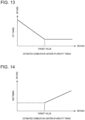
- Fig. 12 is a graph illustrating a comparison of the heat release rate under conditions of the different second timings t_F3.
- the second timing t_F3 when the heat release rate has a solid-line waveform dQ31 in Fig. 12 is earlier (advance side) than the second timing t_F3 when the heat release rate has a broken-line waveform dQ32.
- the combustion center-of-gravity timing is advanced as the second timing t_F3 becomes later, unlike the first timing t_F2. This is because diffusion of fuel inside the cavity 40 near the compression top dead center is suppressed when the second compression-stroke injection F3 is carried out at a later timing, which forms a richer mixture gas. Therefore, combustion of the mixture gas starts earlier, and the following combustion is also stimulated.
- the ECU 100 determines the second timing t_F3 as illustrated in Fig. 14 .
- the ECU 100 retards the second timing t_F3 as the estimated combustion center-of-gravity timing becomes later (retard side).
- the ECU 100 retards the second timing t_F3 as the retarding amount of the estimated combustion center-of-gravity timing from the target combustion center-of-gravity timing (target value) becomes larger.
- the second timing t_F3 is retarded by a certain rate according to the retarding amount.
- the ECU 100 suspends the second compression-stroke injection F3 and only carries out the first compression-stroke injection F2, and retards the first timing t_F2 as the advancing amount of the estimated combustion center-of-gravity timing from the target combustion center-of-gravity timing becomes larger.
- the ECU 100 carries out both the second compression-stroke injection F3 and the first compression-stroke injection F2, and retards the second timing t_F3 as the retarding amount of the estimated combustion center-of-gravity timing from the target combustion center-of-gravity timing becomes larger.
- the ECU 100 causes the injector 21 to carry out the compression-stroke injection at Step S20 which is executed after Step S19.
- the ECU 100 causes the injector 21 to carry out the first compression-stroke injection F2, and instructs the injector 21 so that the amount of fuel injected by the first compression-stroke injection F2 becomes the first compression-stroke injection amount Q2 determined at Step S18, and the operation timing of the first compression-stroke injection F2 becomes the first timing t_F2 determined at Step S19.
- the ECU 100 causes the injector 21 to carry out the first compression-stroke injection F2 as described above, and causes the injector 21 to carry out the second compression-stroke injection F3. Then, the ECU 100 instructs the injector 21 so that the amount of fuel injected by the second compression-stroke injection F3 becomes the second compression-stroke injection amount Q3 determined at Step S18, and the operation timing of the second compression-stroke injection F3 becomes the second timing t_F3 determined at Step S19. After Step S20, the ECU 100 ends this processing (returns to Step S1).
- the content of the control executed by the ECU 100 in the second range A2 is described.
- the content of the control executed in the second range A2 may not be essential to the invention, but useful to understand the invention.
- SI Spark Ignition
- combustion in which the mixture gas is forcibly combusted by spark ignition inside the combustion chamber 6 is performed. That is, the mixture gas is combusted by ignition energy from the ignition plug 20.
- the ignition plug 20 is activated in the second range A2.
- the ECU 100 determines whether the engine is operated at an operating point in the first range A1. If this determination is NO, and when the engine is operated at an operating point in the second range A2, the ECU 100 carries out a control set for the second range A2 which starts from Step S31.
- the ECU 100 first determines the total injection amount. Similar to the first range A1, also in the second range A2, the total injection amount is set in advance for every engine operating point and is stored in the ECU 100, and the ECU 100 extracts the value corresponding to the current operating point of the engine.
- the ECU 100 determines a target valve timing at Step S32. Moreover, the ECU 100 determines a target fuel injection timing. In the second range A2, all the fuel (all the amount of fuel supplied to the combustion chamber 6 in one combustion cycle) is injected from the injector 21 at a time at a given timing in an intake stroke.
- the target fuel injection timing determined at Step S32 is a target value of the operation timing (start timing) of the fuel injection carried out in the intake stroke.
- the target valve timing and the target fuel injection timing are set in advance for every engine operating point and are stored in the ECU 100, and the ECU 100 extracts the values corresponding to the current operating point of the engine.
- the fuel injection pattern in the second range A2 is not limited to this configuration, and a main part of the fuel may be injected in an intake stroke and the remaining fuel may be injected at a later timing, such as a timing near the compression top dead center.
- the ECU 100 carries out the intake-stroke injection.
- the ECU 100 actuates the injector 21 so that the fuel injection is started at the target fuel injection timing determined at Step S32, which is the given timing in the intake stroke, and the amount of fuel injected from the injector 21 at this time becomes the total injection amount determined at Step S31.
- Step S34 the ECU 100 reads the detected values of the various sensors at the close timing of the intake valve 11 (IVC) similar to Step S15.
- Step S35 the ECU 100 estimates the property inside the combustion chamber 6 at the close timing of the intake valve 11 (IVC) similar to Step S16.
- the ECU 100 estimates the temperature inside the combustion chamber 6 at the close timing of the intake valve 11 (IVC) similar to Step S16.
- the ECU 100 determines the ignition timing (the timing at which the ignition plug 20 ignites) based on the temperature inside the combustion chamber 6 at the close timing of the intake valve 11 (IVC) estimated at Step S35.
- Step S37 the ECU 100 instructs the ignition plug 20 to perform an ignition at the ignition timing determined at Step S36.
- the throttle valve 25 is maintained substantially at the fully open.
- the opening of the throttle valve 25 is changed so that the target value of the intake air amount set in advance for each operating point is achieved.
- the second compression-stroke injection F3 is carried out in addition to the intake-stroke injection F1 and the first compression-stroke injection F2 so that a part of the fuel is injected toward the cavity 40. Therefore, the fuel concentration inside the cavity 40 is increased to stimulate the combustion of the mixture gas inside the cavity 40 (as a result, the mixture gas inside the entire combustion chamber 6), thereby preventing the combustion becoming excessively slow. That is, the proper compression self-ignition combustion can be achieved.
- the second compression-stroke injection F3 is suspended. Therefore, the combustion can be prevented from becoming excessively stimulated by the execution of the second compression-stroke injection F3, i.e., the increase in combustion noise can be prevented.
- the increase in combustion noise can be prevented by supplying the fuel to the radially-outward part of the combustion chamber 6 by the execution of the first compression-stroke injection F2 and effectively cooling the radially-outward part.
- the estimated combustion center-of-gravity timing is calculated so as to become an earlier timing as the IVC in-cylinder temperature increases.
- the second compression-stroke injection F3 is carried out in addition to the first compression-stroke injection F2, and when the IVC in-cylinder temperature is equal to or higher than the temperature at which the target combustion center-of-gravity timing can be achieved, the first compression-stroke injection F2 is carried out and the second compression-stroke injection F3 is suspended.
- the IVC in-cylinder temperature is estimated, and according to the estimated combustion center-of-gravity timing which is estimated based on the estimated IVC in-cylinder temperature (IVC estimated in-cylinder temperature), the ratios of the first compression-stroke injection amount Q2 and the second compression-stroke injection amount Q3 are changed. Therefore, the first compression-stroke injection amount Q2 and the second compression-stroke injection amount Q3 can be adjusted to suitable amounts according to the IVC in-cylinder temperature.
- the ratio of the first compression-stroke injection amount Q2 to the compression-stroke injection amount is reduced and the ratio of the second compression-stroke injection amount Q3 to the compression-stroke injection amount is increased, as the estimated combustion center-of-gravity timing is later.
- the first timing t_F2 is advanced as the estimated combustion center-of-gravity timing is later.
- the second timing t_F3 is retarded as the estimated combustion center-of-gravity timing is later. Therefore, the combustion center-of-gravity timing can be securely brought closer to the target combustion center-of-gravity timing, and the proper compression self-ignition combustion can be carried out more securely.
- the intake-stroke injection is carried out in the first range A1 to inject a part of the fuel from the injector 21 in the intake stroke. Therefore, mixing of a portion of the fuel with air can be stimulated to prevent the increase in soot more securely.
- the ratios of the first compression-stroke injection amount Q2 and the second compression-stroke injection amount Q3, and the execution timings for these injections are determined according to the estimated combustion center-of-gravity timing.
- the ratios and the timings may be determined based on the IVC estimated in-cylinder temperature, without estimating the combustion center-of-gravity timing.
- the ratio of the first compression-stroke injection amount Q2 to the compression-stroke injection amount is reduced (the ratio of the second compression-stroke injection amount Q3 to the compression-stroke injection amount is increased) as the IVC estimated in-cylinder temperature decreases.
- the first timing t_F2 is made earlier (advanced) as the IVC estimated in-cylinder temperature decreases.
- the second timing t_F3 is made later (retarded) as the IVC estimated in-cylinder temperature decreases.
- the intake-stroke injection is carried out in the first range A1
- the intake-stroke injection may not be carried out in the first range A1.
- the first compression-stroke injection F2 may be suspended when carrying out the second compression-stroke injection F3 (in the above embodiment, when the estimated combustion center-of-gravity timing is later than the target combustion center-of-gravity timing).
- the IVC in-cylinder temperature is estimated based on the internal EGR rate, the intake air temperature, the intake air amount, the engine load, and the engine water temperature
- an in-cylinder pressure sensor which is configured to measure the in-cylinder pressure which is the pressure inside the combustion chamber 6 may be provided, and the IVC in-cylinder temperature may be estimated based on the detected value of the in-cylinder pressure sensor, in addition to or instead of the parameters described above.
Description
- The present disclosure relates to a control device for a compression self-ignition engine which includes a combustion chamber defined by a cylinder and a piston fitted in the cylinder, and an intake valve which opens and/or closes an intake port to introduce intake air into the combustion chamber. Compression self-ignition (CI) combustion in which a mixture gas of fuel and air combusts by self-ignition inside the combustion chamber is performed at least in a part of an operating range of the engine. The present disclosure also relates to a compression self-ignition engine, a method of controlling a compression self-ignition engine, and a computer program product.
- For engines mounted on automobiles, it has been considered to perform compression self-ignition combustion (CI combustion), instead of a combustion mode in which a spark plug forcibly ignites a mixture gas by jump-spark ignition. The compression self-ignition combustion is a combustion mode in which the mixture gas formed inside a combustion chamber (inside a cylinder) is compressed by a piston so that the mixture gas becomes high in temperature and pressure to combust by self-ignition, not by the jump-spark ignition. The compression self-ignition combustion is believed to provide higher thermal efficiency, because concurrent self-ignition of the mixture gas at multiple locations of the combustion chamber reduces the combustion duration as compared to the combustion by the jump-spark ignition. However, the compression self-ignition combustion has the problem of a tendency of increasing combustion noise, because the self-ignition of the mixture gas in various areas causes a rapid increase in the in-cylinder pressure.
- As an engine to which the compression self-ignition combustion is applied, for example,
JP2012-241589A JP2012-241589A - However, even the configuration of
JP2012-241589A JP2012-241589A -
US 2017/211499 A1 describes an internal combustion engine comprising the fuel injector arranged in the combustion chamber. The primary fuel injection and the secondary fuel injection from the fuel injector are successively performed to cause autoignition of an injected fuel of the primary fuel injection and autoignition of an injected fuel of the secondary fuel injection. -
US 2006/243241 A1 relates to methods for robust controlled auto-ignition and spark ignited combustion controls in gasoline direct-injection engines, including transients, using either exhaust re-breathing or a combination of exhaust re-compression and re-breathing valve strategy. - The present disclosure is made in view of the above situations, and one purpose thereof is to perform compression self-ignition combustion while reliably reducing an increase in combustion noise.
- The invention is a control device for a compression self-ignition engine as defined in
claim 1 or a method as defined inclaim 12. - According to the invention, under the first condition in which the temperature inside the combustion chamber at the close timing of the intake valve is high (i.e., under the condition where the temperature inside the combustion chamber near a compression top dead center becomes high and the mixture gas easily combusts), the first injection is carried out in which the fuel is injected at the first timing at which the fuel goes toward the part radially outward of the cavity. Thus, the temperature at the radially-outward part of the combustion chamber, which is the part where the temperature becomes low easier than the center part of the combustion chamber, is further lowered by the latent heat of vaporization of the fuel in the first injection. As a result, near the compression top dead center, the temperature inside the combustion chamber is unevenly distributed, which prevents that all the mixture gas inside the combustion chamber combusts concurrently. In addition, under the first condition, the second injection in which the fuel is injected at the second timing at which the fuel goes toward the cavity, is suspended. Thus, it can be prevented that a rich mixture gas is formed in the cavity at high temperature, and this rich mixture gas and the mixture gas inside the combustion chamber rapidly combust. As a result, the pressure inside the combustion chamber is prevented from rising rapidly and the increase in combustion noise can be reduced.
- Moreover, under the second condition in which the temperature inside the combustion chamber at the close timing of the intake valve is low and accordingly the mixture gas is comparatively difficult to combust, the second injection is carried out and the rich mixture gas is formed inside the cavity at the comparatively high temperature at the timing nearer to the compression top dead center. Thus, this rich mixture gas and the mixture gas inside the combustion chamber can surely carry out self-ignition.
- Therefore, the increase in combustion noise is reduced securely and proper compression self-ignition combustion (CI combustion) can be achieved.
- While the CI combustion is performed or in order to perform the CI combustion, the injection controller may determine a ratio of a first injection amount that is an amount of fuel injected at the first timing and a ratio of a second injection amount that is an amount of fuel injected at the second timing based on an intake valve close timing (IVC) estimated in-cylinder temperature that is the estimated temperature inside the combustion chamber.
- According to this configuration, since the ratios of the first injection amount and the second injection amount are determined according to the temperature of the combustion chamber at the close timing of the intake valve (i.e., according to the combustibility of the mixture gas), the combustion is prevented from occurring excessively early or excessively late, and thus, the proper compression self-ignition combustion (CI combustion) can be carried out more securely.
- While the CI combustion is performed or in order to perform the CI combustion, the injection controller may determine the first timing and the second timing based on the IVC estimated in-cylinder temperature.
- According to this configuration, the first injection and the second injection are carried out at suitable timings according to the temperature of the combustion chamber at the close timing of the intake valve (i.e., according to the combustibility of the mixture gas) and, thus, the proper compression self-ignition combustion (CI combustion) can be carried out furthermore securely.
- While the CI combustion is performed or in order to perform the CI combustion, the injection controller may estimate a combustion center-of-gravity timing based on the IVC estimated in-cylinder temperature so that the combustion center-of-gravity timing becomes earlier as the IVC estimated in-cylinder temperature increases. The injection controller may determine the first injection amount and the second injection amount so that the ratio of the second injection amount to the sum of the first injection amount and the second injection amount becomes larger as the estimated combustion center-of-gravity timing is later. The injection controller may determine the first timing so that the first timing becomes earlier as the estimated combustion center-of-gravity timing is later, and/or determine the second timing so that the second timing becomes later as the estimated combustion center-of-gravity timing is later.
- When the temperature of the combustion chamber at the close timing of the intake valve is high, the temperature of the mixture gas near the compression top dead center becomes high easily, and the combustion center-of-gravity timing becomes earlier. Accordingly, in this configuration, the combustion center-of-gravity timing is estimated based on the IVC estimated in-cylinder temperature so that the combustion center-of-gravity timing becomes earlier as the IVC estimated in-cylinder temperature increases. Thus, the combustion center-of-gravity timing is estimated properly. Further, according to this configuration, by changing the ratios of the first injection amount and the second injection amount, and the first timing and the second timing based on the estimated combustion center-of-gravity timing, the combustion center-of-gravity timing can be set more suitably and the more proper compression self-ignition combustion can be carried out.
- Here, the present inventors obtained the knowledge that the combustion center-of-gravity timing becomes earlier as the ratio of the second injection amount to the sum of the first injection amount and the second injection amount is larger, the knowledge that the combustion center-of-gravity timing becomes later as the first timing is later, and the knowledge that the combustion center-of-gravity timing becomes later as the second timing is earlier. Accordingly, in this configuration, the ratio described above and the first and second timings are determined based on the estimated combustion center-of-gravity timing as described above, therefore, the combustion center-of-gravity timing can suitably be set more securely.
- While the CI combustion is performed or in order to perform the CI combustion, the injection controller may cause the fuel injection system to carry out an intake-stroke injection to inject fuel in an intake stroke, particularly in addition to the first injection and/or the second injection.
- According to this configuration, mixing of a part of the fuel injected in the intake stroke with air can be stimulated to prevent the increase in soot more securely.
- Particularly, a compression self-ignition engine includes the above control device.
- Further particularly, a computer program product includes computer-readable instructions which, when loaded and executed on the above control device, perform the above method.
-
-
Fig. 1 is a view illustrating the entire configuration of a compression self-ignition engine according to one embodiment of the present disclosure. -
Fig. 2 is a block diagram illustrating a control system of the engine. -
Fig. 3 is a view illustrating one example of a control map of the engine. -
Fig. 4 is a time chart illustrating the contents of a control in a first range. -
Fig. 5 is a view schematically illustrating a situation of a fuel spray by a first compression-stroke injection. -
Fig. 6 is a view schematically illustrating a situation of a fuel spray by a second compression-stroke injection. -
Fig. 7 is a flowchart illustrating a control procedure of the engine. -
Fig. 8 is a graph illustrating a relationship between an IVC in-cylinder temperature and a combustion center-of-gravity timing. -
Fig. 9 is a graph illustrating a comparison of a heat release rate under conditions of different ratios of a second injection amount and a compression-stroke injection amount. -
Fig. 10 is a graph illustrating a relationship between an estimated combustion center-of-gravity timing and ratios of the first injection amount and the second injection amount. -
Fig. 11 is a graph illustrating a comparison of the heat release rate under conditions of different first timings. -
Fig. 12 is a graph illustrating a comparison of the heat release rate under conditions of different second timings. -
Fig. 13 is a graph illustrating a relationship between the estimated combustion center-of-gravity timing and the first timing. -
Fig. 14 is a graph illustrating a relationship between the estimated combustion center-of-gravity timing and the second timing. -
Fig. 1 is a view illustrating the overall configuration of a compression self-ignition engine to which a control device for the compression self-ignition engine according to one embodiment of the present disclosure is applied. Below, the compression self-ignition engine is simply referred to as the "engine." The engine illustrated in this figure is a four-cycle engine mounted on a vehicle as a power source for propelling the vehicle (e.g., an automobile). The engine includes anengine body 1, anintake passage 28 where intake air introduced into theengine body 1 circulates, and anexhaust passage 29 where exhaust gas discharged from theengine body 1 circulates. - The
engine body 1 includes acylinder block 3 where thecylinder 2 is formed therein, acylinder head 4 attached to an upper surface of thecylinder block 3 to cover thecylinder 2 from above, and apiston 5 reciprocatably fitted in thecylinder 2. Although theengine body 1 is typically a multiple cylinder type having a plurality of cylinders (e.g., four cylinders line up in a direction perpendicular to the drawing sheet ofFig. 1 ), only onecylinder 2 is described herein for simplifying the description. - Above the
piston 5, acombustion chamber 6 is defined by thepiston 5 and thecylinder 2. Fuel is supplied to thecombustion chamber 6 by an injection from an injector 21 (described later). The supplied fuel is mixed with air and combusts inside thecombustion chamber 6, and an expansion force caused by the combustion depresses thepiston 5, thereby thepiston 5 reciprocating in the up-and-down direction. Below thepiston 5, a crankshaft 7 which is an output shaft of theengine body 1 is provided. The crankshaft 7 is coupled to thepiston 5 via a connecting rod 8, and it is rotated on the center axis by the reciprocating motion (vertical motion) of thepiston 5. In this embodiment, the engine is a gasoline engine which mainly uses gasoline as fuel, and fuel which contains only gasoline, or contains a secondary component, such as bioethanol, in addition to gasoline, is supplied to theengine body 1. - A
concave cavity 40 is formed in a center part of acrown surface 5a of thepiston 5. Thecavity 40 is dented downwardly (the opposite side from the cylinder head 4). In this embodiment, a bottom surface of thecavity 40 is formed in a gentle mountain shape, and has a peak part in a radial center part of thecrown surface 5a of thepiston 5 and thecavity 40. An inner circumferential part of the bottom surface of thecavity 40 is formed so that its height is gradually lowered to the radially outside from the radially-central peak part, and the height is again gradually raised to the radially outside in a radially-outward part. - An
intake port 9 for supplying intake air to thecombustion chamber 6 and anexhaust port 10 for discharging exhaust gas inside thecombustion chamber 6 are formed in thecylinder head 4. Theintake port 9 and theexhaust port 10 open to thecombustion chamber 6. Thecylinder head 4 is provided with anintake valve 11 which opens and closes theintake port 9, and anexhaust valve 12 which opens and closes theexhaust port 10. Note that the valve type of the engine of this embodiment is 4-valve type comprised of two intake valves and two exhaust valves, where twointake ports 9, twoexhaust ports 10, twointake valves 11, and twoexhaust valves 12 are provided to eachcylinder 2. - The
intake valve 11 and theexhaust valve 12 are interlocked with the rotation of the crankshaft 7 throughvalve operating mechanisms cylinder head 4 and opens and closes thevalves - An intake-
valve variable mechanism 15 which can change at least an open timing of theintake valve 11 is built in thevalve operating mechanism 13 for theintake valve 11. Similarly, an exhaust-valve variable mechanism 16 which can change at least a close timing of theexhaust valve 12 is built in thevalve operating mechanism 14 for theexhaust valve 12. By controlling the intake-valve variable mechanism 15 and the exhaust-valve variable mechanism 16, a valve overlap period where both theintake valve 11 and theexhaust valve 12 open can be changed. In addition, by changing the valve overlap period, an amount of burnt gas (internal exhaust gas recirculation (EGR) gas) which remains inside thecombustion chamber 6 is changed. Note that the intake-valve variable mechanism 15 (or the exhaust-valve variable mechanism 16) may be a variable mechanism which changes only the close timing (or the open timing) while the open timing (or the close timing) of the intake valve 11 (or the exhaust valve 12) is fixed, or may be a phase-type variable mechanism which simultaneously changes the open timing and the close timing of the intake valve 11 (or the exhaust valve 12). - The
cylinder head 4 is provided with a set of theinjector 21 which injects fuel (mainly gasoline) into thecombustion chamber 6, and anignition plug 20 which ignites a mixture gas of fuel injected into thecombustion chamber 6 from theinjector 21 and air introduced into thecombustion chamber 6, percylinder 2. - The
injector 21 is a multiple nozzle hole type which has a plurality of nozzle holes at a tip-end part thereof. Theinjector 21 is provided to a center part of aceiling surface 6a (a lower surface of thecylinder head 4 which covers the combustion chamber 6) of thecombustion chamber 6 so that its tip-end part opposes to the part which constitutes the peak part described above of the center part of thecrown surface 5a of thepiston 5 and of the center part of thecavity 40. Fuel is injected radially from the nozzle holes of theinjector 21. In detail, each nozzle hole of theinjector 21 is formed so that its opening end is oriented obliquely downward, and outward in the bore radial direction, and therefore, the fuel injected from each nozzle hole is radially injected so that it spreads outside in the bore radial direction as it approaches thecrown surface 5a of thepiston 5. Theinjector 21 is connected to afuel feed pipe 23, and fuel supplied through thefuel feed pipe 23 is injected from the tip-end part of theinjector 21. Thisinjector 21 is an example of a "fuel injection system" in the present disclosure. - The ignition plug 20 is provided at a position deviated slightly from the
injector 21 so that it faces the inside of thecombustion chamber 6 from theceiling surface 6a of thecombustion chamber 6. - The
intake passage 28 is connected to one side surface of thecylinder head 4 so as to communicate with theintake port 9. Air (fresh air) taken in from an upstream end of theintake passage 28 is introduced into thecombustion chamber 6 through theintake passage 28 and theintake port 9. Theintake passage 28 is provided with athrottle valve 25 and asurge tank 28b, sequentially in this order from upstream. Thethrottle valve 25 opens and closes theintake passage 28 to adjust an amount of air which passes through theintake passage 28. - The
exhaust passage 29 is connected to the other side surface of thecylinder head 4 so as to communicate with theexhaust port 10. Burnt gas (exhaust gas) generated in thecombustion chamber 6 is discharged outside through theexhaust port 10 and theexhaust passage 29. Theexhaust passage 29 is provided with acatalytic converter 35 which purifies exhaust gas. For example, a three-way catalyst is built in thecatalytic converter 35. - The
cylinder block 3 is provided with a crank angle sensor SN1 which detects a rotational angle of the crankshaft 7 (i.e., an engine speed). A water jacket (not illustrated) where coolant circulates is formed inside thecylinder block 3 and thecylinder head 4 of theengine body 1, and thecylinder block 3 is also provided with a water temperature sensor SN2 which detects a temperature of the coolant inside the water jacket. - An air flow sensor SN3 which detects an intake air amount which is an amount of air introduced into the
cylinder 2, and an intake pressure sensor SN5 which detects an intake pressure which is a pressure of the air introduced into thecylinder 2 are disposed in theintake passage 28. The air flow sensor SN3 is disposed downstream of an air cleaner, and it detects a flow rate of air passing through this part. The intake pressure sensor SN5 is disposed at thesurge tank 28b, and it detects a pressure of intake air passing through thesurge tank 28b. -
Fig. 2 is a block diagram illustrating a control system of the engine. An electronic control unit (ECU) 100 illustrated in this figure is a control device comprised of a microcomputer for comprehensively controlling the engine, and is comprised of a processor (e.g., central processing unit (CPU)), ROM, RAM, etc., which are well known. TheECU 100 is configured to control theinjector 21 as will be described later, and it is an example of an "injection controller" in the present disclosure. - Detected information by the various sensors are inputted into the
ECU 100. For example, theECU 100 is electrically connected to the crank angle sensor SN1, the water temperature sensor SN2, the air flow sensor SN3, an intake air temperature sensor SN4, and the intake pressure sensor SN5. The information detected by these sensors SN1 to SN5 (i.e., the information, such as the engine speed, the engine water temperature, the intake air amount, the intake air temperature, and the intake pressure) are sequentially inputted into theECU 100. Moreover, an accelerator opening sensor SN6 is provided to the vehicle, which detects an accelerator opening which is an opening of an accelerator pedal operated by a driver operating the vehicle. The detected information by the accelerator opening sensor SN6 is also sequentially inputted into theECU 100. - The
ECU 100 controls each part of the engine, while performing various determinations and calculations based on the information inputted from the sensors SN1 to SN6. That is, theECU 100 is electrically connected with theinjector 21, theignition plug 20, thethrottle valve 25, the intake valve 11 (the intake-side valve operating mechanism 13), and the exhaust valve 12 (the exhaust-side valve operating mechanism 14), and outputs control signals to these components based on the results of the determinations and calculations. -
Fig. 3 is a map illustrating a difference in the control according to the engine speed and the engine load. As illustrated in this figure, an operating range of the engine is roughly divided into two sub ranges (i.e., a first range A1 and a second range A2). The second range A2 may not necessarily be essential. - The first range A1 is a low-speed low-load range where the engine speed is a given switching engine speed N1 or lower and the engine load is a given switching load Tq1 or lower. The second range A2 is the remaining range other than the first range A1. Note that the switching load Tq1 is set so as to become lower as the engine speed increases. The first range A1 may include the remaining range other than the low-speed low-load range.
- The content of the control executed by the
ECU 100 in the first range A1 is described. In the first range A1, CI (Compression Ignition) combustion in which the mixture gas of fuel and air combusts inside thecombustion chamber 6 by self-ignition is performed. That is, the mixture gas combusts only by a compression of thepiston 5, without igniting the fuel by theignition plug 20. Thus, theignition plug 20 is stopped in the first range A1. In other words, in the first range A1, only CI combustion is performed. -
Fig. 4 is a view illustrating a fuel injection timing (a timing at which fuel is injected from the injector 21), lift characteristics of theintake valve 11 and theexhaust valve 12, and a heat release rate (J/deg) to be generated, when the engine is operated at a representative operating point in the first range A1. All of the features as shown inFig. 4 may not necessarily essential. - As illustrated in
Fig. 4 , in the first range A1, theexhaust valve 12 is opened also during an intake stroke, and exhaust gas once discharged to theexhaust port 10 from thecombustion chamber 6 is again introduced back into thecombustion chamber 6. That is, in the first range A1, internal EGR in which burnt gas remains inside thecombustion chamber 6 is carried out. In this embodiment, a close timing of the exhaust valve 12 (EVC) is retarded from an exhaust top dead center so that theexhaust valve 12 is opened across the exhaust top dead center. The opening and closing operation of theexhaust valve 12 is not limited to the operation as described above and/or as disclosed inFig. 4 , and may not necessarily be essential for the CI combustion. Note that the opening and closing operation of theexhaust valve 12 for carrying out the internal EGR may be, but not limited to be, one in which theexhaust valve 12 is opened twice by being opened again in an intake stroke after theexhaust valve 12 is closed once near an exhaust top dead center. In addition, in the first range A1, the close timing of the exhaust valve 12 (EVC) is retarded from the open timing of the intake valve 11 (IVO) so that the valve overlap in which both theintake valve 11 and theexhaust valve 12 open during a given period of time is carried out. - In the first range A1, an intake-stroke injection F1 in which fuel is injected into the
combustion chamber 6 from theinjector 21 in an intake stroke, and/or a compression-stroke injection in which fuel is injected in a compression stroke are carried out. Here, fundamentally, as illustrated by a solid line inFig. 4 , the fuel injection is only performed once during the compression stroke, but in the first range A1, a fuel injection F3 illustrated by a broken line may further be performed during the compression stroke. That is, under a given condition in the first range A1, the intake-stroke injection F1, a first compression-stroke injection F2 in which fuel is injected in a compression stroke, and the second compression-stroke injection F3 in which fuel is injected at a timing in the compression stroke later than the first compression-stroke injection F2 are carried out. Thus, in this embodiment, theinjector 21 is possible to inject fuel dividedly twice in the compression stroke. - Operation timing (start timing) of the intake-stroke injection F1 is in the first half of an intake stroke, for example, 60°CA (CA: crank angle) after an exhaust top dead center (i.e., about -300°CA before a compression top dead center).
- A first timing t_F2 which is an operation timing (start timing) of the first compression-stroke injection F2 is set at a timing when fuel injected by the first compression-stroke injection F2 from the
injector 21 goes toward the part radially outward of thecavity 40. That is, the first timing t_F2 is set so that, as illustrated inFig. 5 , a line X1 along an axis of a fuel spray Fm of fuel injected from theinjector 21 passes through the part radially outward of thecavity 40. For example, the operation timing of the first compression-stroke injection F2 is set at a timing of 1 80°CA to 90°CA before a compression top dead center. The first compression-stroke injection F2 is an example of a "first injection" in the present disclosure. - A second timing t_F3 which is the operation timing (start timing) of the second compression-stroke injection F3 is set at a timing when fuel injected by the second compression-stroke injection F3 from the
injector 21 goes toward thecavity 40 in thepiston 5. That is, the second timing t_F3 is set so that, as illustrated inFig. 6 , the line X1 along the axis of the fuel spray Fm of the fuel injected from theinjector 21 intersects with the bottom surface of thecavity 40. For example, the operation timing of the second compression-stroke injection F3 is set at a timing of 35°CA to 5°CA before a compression top dead center. The second compression-stroke injection F3 is an example of a "second injection" in the present disclosure. - The fuel is injected in the first range A1 dividedly by the intake-stroke injection F1 and the first compression-stroke injection F2 in order to control an increase in combustion noise while reducing generation of soot.
- In detail, since a time to the compression top dead center is short when all the fuel is supplied to the
combustion chamber 6 in the compression stroke, the combustion may occur without the fuel and air being fully mixed, thereby increasing the generating amount of soot. On the other hand, when all the fuel is supplied to thecombustion chamber 6 in the intake stroke, a comparatively rich (fuel concentration is high) mixture gas is formed entirely in thecombustion chamber 6. As a result, the mixture gas may carry out self-ignition simultaneously at multiple locations inside thecombustion chamber 6 near the compression top dead center to abruptly increase an in-cylinder pressure (a pressure inside the combustion chamber), thereby increasing the combustion noise. - Therefore, in this embodiment, by dividing the fuel injection into the intake-stroke injection F1 and the first compression-stroke injection F2 as described above, mixing of a portion of the fuel with air is facilitated to reduce the generation of soot, while shifting the combustion start timing at multiple locations inside the
combustion chamber 6 to prevent the increase in the combustion noise. - In particular, as described above, the first compression-stroke injection F2 is carried out so that fuel injected from the
injector 21 goes toward the part radially outward of thecavity 40. Therefore, the increase in the combustion noise is effectively prevented. - In detail, the temperature at the radially-outward part of the
combustion chamber 6 is kept lower than the temperature of the center part by radiation of heat from a wall surface of thecombustion chamber 6. In this state, when fuel is injected to the radially-outward part of thecavity 40, the temperature at the radially-outward part is further lowered than the temperature of thecavity 40 by latent heat of vaporization of the fuel. Thus, the execution of the first compression-stroke injection F2 increases a temperature difference between the temperature of a radially-outward part of thecavity 40 and the temperature of a center part in thecombustion chamber 6 to securely avoid that the mixture gas in the radially-outward part of thecavity 40 and the mixture gas in the center part in thecombustion chamber 6 start combustion simultaneously. Therefore, the rapid rise in the in-cylinder pressure inside thecombustion chamber 6 and the increase in combustion noise are securely prevented. - As described above, in the first range A1, by carrying out the intake-stroke injection F1 and the first compression-stroke injection F2, it is thought that both the increase in soot and the increase in combustion noise can be prevented.
- However, when the
combustion chamber 6 is in a state where the mixture gas is difficult to combust inside thecombustion chamber 6, the mixture gas may not properly self-ignite when only the intake-stroke injection F1 and the first compression-stroke injection F2 are performed. In detail, as described above, the temperature of the center part of the combustion chamber 6 (i.e., the temperature inside the cavity 40) is higher than the temperature of the radially-outward part. Thus, inside thecombustion chamber 6, the mixture gas inside thecavity 40 first starts combustion, and mixture gas at the radially-outward side then combusts. However, as described above, since the first compression-stroke injection F2 is to inject fuel to the radially-outward part of thecavity 40, the concentration of fuel inside thecavity 40 can be kept low. Therefore, since the combustion of the mixture gas inside thecavity 40 becomes slower under the atmosphere in which the mixture gas is difficult to combust, the combustion in theentire combustion chamber 6 becomes also slower, that is, a combustion center-of-gravity timing is retarded from a desired timing, thereby reducing the engine torque below a desired torque. - Thus, in this embodiment, when the
combustion chamber 6 is in the state where the mixture gas is difficult to combust inside thecombustion chamber 6 and the combustion center-of-gravity timing is estimated to be retarded from the desired timing in the first range A1, the second compression-stroke injection F3 described above is carried out. By carrying out the second compression-stroke injection F3, the fuel concentration inside thecavity 40 is increased to stimulate the combustion of the mixture gas, and therefore, the combustion center-of-gravity timing is advanced. Here, the term "combustion center-of-gravity timing" as used herein refers to a timing at which a generation of 50% of the total amount of heat release to be generated inside thecombustion chamber 6 in one combustion cycle is finished. - Further, in this embodiment, the operation timing of the first compression-stroke injection F2 is adjusted so that the combustion center-of-gravity timing occurs at the desired timing even when the second compression-stroke injection F3 is suspended. Moreover, when both the first compression-stroke injection F2 and the second compression-stroke injection F3 are carried out, the operation timings of the first compression-stroke injection F2 and the second compression-stroke injection F3, and ratios of a first compression-stroke injection amount Q2 which is an amount of fuel injected by the first compression-stroke injection F2 and a second compression-stroke injection amount Q3 which is an amount of fuel injected by the second compression-stroke injection F3 are adjusted so that the combustion center-of-gravity timing occurs at the desired timing.
-
Fig. 7 is a flowchart illustrating a part of a control procedure executed by theECU 100. An adjustment control of the operation timings of the compression-stroke injections F2 and F3, and the ratio of the injection amounts is described with reference toFig. 7 . All of the steps as shown inFig. 7 may not necessarily be essential. - At Step S1, the
ECU 100 reads the detected values from the various sensors. For example, theECU 100 reads the engine speed, the engine water temperature, the intake air amount, the intake air temperature, the intake pressure, and the accelerator opening which are detected by the sensors SN1 to SN6. - Next, at Step S2, the
ECU 100 determines whether the engine is operated at an operating point in the first range A1. In detail, theECU 100 calculates the engine load based on the accelerator opening and the engine speed, and determines whether the current operating point of the engine is included in the first range A1 based on the calculated engine load and the engine speed. - If the determination at Step S2 is YES, and when the engine is operated at an operating point in the first range A1, the
ECU 100 shifts to Step S11. - At Step S11, the
ECU 100 determines a target internal EGR rate, a target combustion center-of-gravity timing, a total injection amount, an intake-stroke injection amount, an intake-stroke injection timing t_F1, and a reference first timing t_F2. - The target internal EGR rate is a target value of the internal EGR rate which is a ratio of an amount (weight) of internal EGR gas (burnt gas which remains inside the
combustion chamber 6 by the execution of internal EGR) to the total gas amount (weight) inside thecombustion chamber 6. The target combustion center-of-gravity timing is a target value of the combustion center-of-gravity timing. - The target internal EGR rate and the target combustion center-of-gravity timing are set in advance for every engine operating point and are stored in the
ECU 100, and theECU 100 extracts the target internal EGR rate and the target combustion center-of-gravity timing corresponding to the current operating point of the engine. For example, the target internal EGR rate, the combustion center-of-gravity, and the intake-stroke injection amount are set in advance corresponding to the engine speed and the engine load and are stored in theECU 100 in the form of a map, and theECU 100 extracts values corresponding to the current engine speed and the engine load from each map. - The total injection amount is the total amount of fuel injected into the
combustion chamber 6 in one combustion cycle. The intake-stroke injection amount is an amount of fuel injected into thecombustion chamber 6 by the intake-stroke injection F1. The intake-stroke injection timing t_F1 is an operation timing (start timing) of the intake-stroke injection F1. - The total injection amount, the intake-stroke injection amount, and the intake-stroke injection timing t_F1 are set in advance for every engine operating point and are stored in the
ECU 100, and theECU 100 extracts each value corresponding to the current operating point of the engine. For example, the total injection amount, the intake-stroke injection amount, and the intake-stroke injection timing t_F1 are set in advance corresponding to the engine speed and the engine load and are stored in theECU 100 in the form of a map, and theECU 100 extracts values corresponding to the current engine speed and the engine load from each map. - The reference first timing t_F2 is a reference value of the first timing t_F2. The reference first timing t_F2 is set in advance at a timing at which, while the state inside the
combustion chamber 6 is a reference state, the target combustion center-of-gravity timing is achieved when the second compression-stroke injection F3 is suspended and the intake-stroke injection F1 and the first compression-stroke injection F2 are carried out. Note that the term "reference state" as used herein refers to, for example, a state where the steady operation of the engine is carried out and the temperature, the pressure, and the gas composition inside thecombustion chamber 6 are a target temperature, a target pressure, and a target gas composition (most suitable for fuel efficiency, combustion noise, and exhaust performance). - Next, at Step S12, the
ECU 100 determines a target valve timing. The target valve timing includes target values of the open timings and the close timings of theintake valve 11 and theexhaust valve 12. TheECU 100 calculates the target valve timing at which the target internal EGR rate can be achieved based on the target internal EGR rate determined at Step S11, the intake air amount, the intake pressure, etc. - Next, at Step S13, the
ECU 100 issues commands to the intake-valve variable mechanism 15 and the exhaust-valve variable mechanism 16 so that theintake valve 11 and theexhaust valve 12 open and/or close at the target valve timing determined at Step S12. - Next, at Step S14, the
ECU 100 carries out the intake-stroke injection F1. In detail, theECU 100 actuates theinjector 21 so that the fuel injection from theinjector 21 is started at the intake-stroke injection timing t_F1 determined at Step S11 and the amount of fuel injected at this time becomes the intake-stroke injection amount determined at Step S11. - Next, at Step S15, the
ECU 100 reads the detected values of the various sensors at the close timing of the intake valve 11 (IVC). That is, Steps S1, S2, and S11 to S14 are performed in a given combustion cycle, before the close timing of the intake valve 11 (IVC), and further, particularly before the open timing of the exhaust valve 12 (EVO), and Step S15 is performed in the same combustion cycle at or just after the close timing of the intake valve 11 (IVC). - Next, at Step S16, the
ECU 100 estimates properties inside thecombustion chamber 6 at the close timing of the intake valve 11 (IVC) based on the detected values of the various sensors read at Step S15. In detail, theECU 100 estimates the intake air amount and the internal EGR rate inside thecombustion chamber 6 at the close timing of the intake valve 11 (IVC). For example, theECU 100 estimates an exhaust pressure which is a pressure inside theexhaust port 10 based on the engine speed, the engine load, the intake air amount, the intake pressure, and the open timings and the close timings of theintake valve 11 and theexhaust valve 12, and estimates the intake air amount inside thecombustion chamber 6 and the internal EGR rate based on a pressure difference between the estimated exhaust pressure and the intake pressure, the intake air amount, the intake air temperature, and the engine speed. Then, theECU 100 estimates the temperature inside thecombustion chamber 6 at the close timing of the intake valve 11 (IVC) based on the estimated intake air amount and internal EGR rate, the intake air temperature, the engine load, and the engine water temperature. For example, theECU 100 estimates the temperature inside thecombustion chamber 6 so that the temperature becomes higher at the close timing of the intake valve 11 (IVC) when the high internal EGR rate is higher, the intake air temperature is higher, and the intake air amount is smaller, the engine load is higher, or the engine water temperature is higher. Moreover, theECU 100 estimates the pressure inside thecombustion chamber 6 at the close timing of the intake valve 11 (IVC). Below, the temperature inside thecombustion chamber 6 at the close timing of the intake valve 11 (IVC) is referred to as an "IVC in-cylinder temperature," and the estimated IVC in-cylinder temperature is referred to as an "IVC estimated in-cylinder temperature." - Next, at Step S17, the
ECU 100 estimates the combustion center-of-gravity timing achieved if the second compression-stroke injection F3 is suspended and the first compression-stroke injection F2 is carried out at the reference first timing based on the values estimated at Step S16 and the detected values of the various sensors read at Step S15. Below, the estimated combustion center of gravity is referred to as an "estimated combustion center-of-gravity timing." In this embodiment, a model formula for calculating the combustion center of gravity is incorporated into theECU 100, and theECU 100 calculates the combustion center of gravity by applying the estimated values and the detected values to the model formula. Here, as described above, the combustion center-of-gravity timing is retarded as the state inside thecombustion chamber 6 is a state where the mixture gas is more difficult to combust, and, on the other hand, the combustion center-of-gravity timing is advanced as the state inside thecombustion chamber 6 is a state where the mixture gas combusts more easily. The mixture gas is easier to combust as the IVC in-cylinder temperature increases. Thus, as illustrated inFig. 8 , the combustion center-of-gravity timing is advanced as the IVC in-cylinder temperature increases. Corresponding to this, theECU 100 estimates the estimated combustion center-of-gravity timing so that, when the engine is operated at the same operating point, the estimated combustion center-of-gravity timing is advanced as the IVC estimated in-cylinder temperature increases. - Next, at Step S18, the
ECU 100 determines the first compression-stroke injection amount Q2, and the second compression-stroke injection amount Q3 based on the estimated value and the target value of the combustion center-of-gravity timing, i.e., the estimated combustion center-of-gravity timing calculated at Step S17 and the target combustion center-of-gravity timing read at Step S11. Below, the sum of the first compression-stroke injection amount Q2 and the second compression-stroke injection amount Q3 is referred to as a "compression-stroke injection amount." - The
ECU 100 first determines ratios of the first compression-stroke injection amount Q2 and the second compression-stroke injection amount Q3. In detail, theECU 100 determines a ratio of the first compression-stroke injection amount Q2 to the compression-stroke injection amount, and a ratio of the second compression-stroke injection amount Q3 to the compression-stroke injection amount. Next, theECU 100 calculates a value obtained by subtracting the intake-stroke injection amount determined at Step S11 from the total injection amount determined also at Step S11, as a compression-stroke injection amount. Then, theECU 100 determines the injection amounts Q2 and Q3 based on the calculated compression-stroke injection amount, and the determined ratios of the injection amounts Q2 and Q3 corresponding to the compression-stroke injection amount. -
Fig. 9 is a graph illustrating a comparison of the heat release rate under conditions of different ratios of the second compression-stroke injection amount Q3 to the compression-stroke injection amount. The ratio of the second compression-stroke injection amount Q3 to the compression-stroke injection amount when a broken-line waveform dQ12 inFig. 9 is obtained becomes larger than the same ratio when a solid-line waveform dQ11 is obtained, and as clear from the waveform comparison, the combustion center-of-gravity timing is advanced as the ratio of the second compression-stroke injection amount Q3 to the compression-stroke injection amount increases. This is because, when the second compression-stroke injection amount Q3 increases, the mixture gas inside thecavity 40 becomes richer to further stimulate the combustion inside thecavity 40 near a compression top dead center. - Corresponding to this, as illustrated in
Fig. 10 , theECU 100 determines the first compression-stroke injection amount Q2 and the second compression-stroke injection amount Q3. Particularly, theECU 100 determines the ratio of the first compression-stroke injection amount Q2 to the compression-stroke injection amount (the ratio = Q21 the compression-stroke injection amount) and the ratio of the second compression-stroke injection amount Q3 to the compression-stroke injection (the ratio = Q3/ the compression-stroke injection amount). Note that the ratio of the second compression-stroke injection amount Q3 to the compression-stroke injection amount is the same as a value obtained by subtracting the ratio of the first compression-stroke injection amount Q2 to the compression-stroke injection amount from 100%. - In detail, the
ECU 100 lowers the ratio of the first compression-stroke injection amount Q2 to the compression-stroke injection amount (raises the ratio of the second compression-stroke injection amount Q3 to the compression-stroke injection amount) as the estimated combustion center-of-gravity timing is retarded. In detail, when the estimated combustion center-of-gravity timing is earlier than the target value (i.e., the target combustion center-of-gravity timing), theECU 100 sets the ratio of the first compression-stroke injection amount Q2 to the compression-stroke injection amount to 100%, and sets the ratio of the second compression-stroke injection amount Q3 to the compression-stroke injection amount to 0%. Moreover, when the estimated combustion center-of-gravity timing is later than the target combustion center-of-gravity timing, theECU 100 lowers the ratio of the first compression-stroke injection amount Q2 to the compression-stroke injection amount as a retarding amount of the estimated combustion center-of-gravity timing from the target combustion center-of-gravity timing increases. In the illustrated example, the ratio of the first compression-stroke injection amount Q2 to the compression-stroke injection amount is lowered by a certain ratio according to the retarding amount. - Returning to
Fig. 7 , theECU 100 shifts to Step S19 after Step S18. At Step S19, theECU 100 determines the first timing t_F2 and the second timing t_F3 based on the estimated combustion center-of-gravity timing calculated at Step S17 and the target combustion center-of-gravity timing read at Step S11. Note that theECU 100 only determines the first timing t_F2 when the ratio of the second compression-stroke injection amount Q3 is determined as 0% at Step S18. -
Fig. 11 is a graph illustrating a comparison of the heat release rate under conditions of different first timings t_F2. The first timing t_F2 when the heat release rate has a solid-line waveform dQ21 inFig. 11 is earlier (advance side) than the first timing t_F2 when the heat release rate has a broken-line waveform dQ22. As clear from the waveform comparison, the combustion center-of-gravity timing is retarded as the first timing t_F2 becomes later. This is because the temperature lowering effect at the radially-outward part of thecombustion chamber 6 becomes larger near a compression top dead center when the first compression-stroke injection F2 is carried out at a later timing, which makes the combustion slower. - Corresponding to this, the
ECU 100 determines the first timing t_F2 as illustrated inFig. 13 . In detail, theECU 100 advances the first timing t_F2 as the estimated combustion center-of-gravity timing is retarded. In detail, when the estimated combustion center-of-gravity timing is earlier than the target combustion center-of-gravity timing (target value), theECU 100 advances the first timing t_F2 as the estimated combustion center-of-gravity timing is retarded. In the example ofFig. 13 , the first timing t_F2 is changed by a certain rate according to the difference between the estimated combustion center-of-gravity timing and the target combustion center-of-gravity timing. Moreover, when the estimated combustion center-of-gravity timing is later than the target combustion center of gravity timing, theECU 100 maintains the first timing t_F2 at a certain value regardless of the change in the estimated combustion center-of-gravity timing, which is the reference first timing at which the target combustion center-of-gravity timing can be achieved. For example, the reference first timing t_F2 is set to 180°CA before a compression top dead center, and the first timing t_F2 is changed between 180°CA before the compression top dead center and 70°CA before the compression top dead center according to the estimated combustion center-of-gravity timing. -
Fig. 12 is a graph illustrating a comparison of the heat release rate under conditions of the different second timings t_F3. The second timing t_F3 when the heat release rate has a solid-line waveform dQ31 inFig. 12 is earlier (advance side) than the second timing t_F3 when the heat release rate has a broken-line waveform dQ32. As clear from the waveform comparison, the combustion center-of-gravity timing is advanced as the second timing t_F3 becomes later, unlike the first timing t_F2. This is because diffusion of fuel inside thecavity 40 near the compression top dead center is suppressed when the second compression-stroke injection F3 is carried out at a later timing, which forms a richer mixture gas. Therefore, combustion of the mixture gas starts earlier, and the following combustion is also stimulated. - Corresponding to this, the
ECU 100 determines the second timing t_F3 as illustrated inFig. 14 . In detail, theECU 100 retards the second timing t_F3 as the estimated combustion center-of-gravity timing becomes later (retard side). In detail, theECU 100 retards the second timing t_F3 as the retarding amount of the estimated combustion center-of-gravity timing from the target combustion center-of-gravity timing (target value) becomes larger. In the example ofFig. 14 , the second timing t_F3 is retarded by a certain rate according to the retarding amount. - Thus, when the estimated combustion center-of-gravity timing is at or advanced from the target combustion center-of-gravity timing, the
ECU 100 suspends the second compression-stroke injection F3 and only carries out the first compression-stroke injection F2, and retards the first timing t_F2 as the advancing amount of the estimated combustion center-of-gravity timing from the target combustion center-of-gravity timing becomes larger. Moreover, when the estimated combustion center-of-gravity timing is at the retard side of the target combustion center of gravity, theECU 100 carries out both the second compression-stroke injection F3 and the first compression-stroke injection F2, and retards the second timing t_F3 as the retarding amount of the estimated combustion center-of-gravity timing from the target combustion center-of-gravity timing becomes larger. - Returning to
Fig. 7 , theECU 100 causes theinjector 21 to carry out the compression-stroke injection at Step S20 which is executed after Step S19. In detail, theECU 100 causes theinjector 21 to carry out the first compression-stroke injection F2, and instructs theinjector 21 so that the amount of fuel injected by the first compression-stroke injection F2 becomes the first compression-stroke injection amount Q2 determined at Step S18, and the operation timing of the first compression-stroke injection F2 becomes the first timing t_F2 determined at Step S19. Moreover, when the ratio of the second compression-stroke injection amount Q3 to the compression-stroke injection is determined as a value larger than 0% at Step S18, theECU 100 causes theinjector 21 to carry out the first compression-stroke injection F2 as described above, and causes theinjector 21 to carry out the second compression-stroke injection F3. Then, theECU 100 instructs theinjector 21 so that the amount of fuel injected by the second compression-stroke injection F3 becomes the second compression-stroke injection amount Q3 determined at Step S18, and the operation timing of the second compression-stroke injection F3 becomes the second timing t_F3 determined at Step S19. After Step S20, theECU 100 ends this processing (returns to Step S1). - The content of the control executed by the
ECU 100 in the second range A2 is described. The content of the control executed in the second range A2 may not be essential to the invention, but useful to understand the invention. In the second range A2, SI (Spark Ignition) combustion in which the mixture gas is forcibly combusted by spark ignition inside thecombustion chamber 6 is performed. That is, the mixture gas is combusted by ignition energy from theignition plug 20. Thus, theignition plug 20 is activated in the second range A2. - A control executed by the
ECU 100 in the second range A2 is described with reference to the flowchart ofFig. 7 . - As described above, at Step S2, the
ECU 100 determines whether the engine is operated at an operating point in the first range A1. If this determination is NO, and when the engine is operated at an operating point in the second range A2, theECU 100 carries out a control set for the second range A2 which starts from Step S31. - At Step S31, the
ECU 100 first determines the total injection amount. Similar to the first range A1, also in the second range A2, the total injection amount is set in advance for every engine operating point and is stored in theECU 100, and theECU 100 extracts the value corresponding to the current operating point of the engine. - Next, the
ECU 100 determines a target valve timing at Step S32. Moreover, theECU 100 determines a target fuel injection timing. In the second range A2, all the fuel (all the amount of fuel supplied to thecombustion chamber 6 in one combustion cycle) is injected from theinjector 21 at a time at a given timing in an intake stroke. The target fuel injection timing determined at Step S32 is a target value of the operation timing (start timing) of the fuel injection carried out in the intake stroke. The target valve timing and the target fuel injection timing are set in advance for every engine operating point and are stored in theECU 100, and theECU 100 extracts the values corresponding to the current operating point of the engine. Note that the fuel injection pattern in the second range A2 is not limited to this configuration, and a main part of the fuel may be injected in an intake stroke and the remaining fuel may be injected at a later timing, such as a timing near the compression top dead center. - At Step S33, the
ECU 100 carries out the intake-stroke injection. In detail, theECU 100 actuates theinjector 21 so that the fuel injection is started at the target fuel injection timing determined at Step S32, which is the given timing in the intake stroke, and the amount of fuel injected from theinjector 21 at this time becomes the total injection amount determined at Step S31. - Next, at Step S34, the
ECU 100 reads the detected values of the various sensors at the close timing of the intake valve 11 (IVC) similar to Step S15. - Next, at Step S35, the
ECU 100 estimates the property inside thecombustion chamber 6 at the close timing of the intake valve 11 (IVC) similar to Step S16. In detail, theECU 100 estimates the temperature inside thecombustion chamber 6 at the close timing of the intake valve 11 (IVC) similar to Step S16. - Next, at Step S36, the
ECU 100 determines the ignition timing (the timing at which theignition plug 20 ignites) based on the temperature inside thecombustion chamber 6 at the close timing of the intake valve 11 (IVC) estimated at Step S35. - Next, at Step S37, the
ECU 100 instructs theignition plug 20 to perform an ignition at the ignition timing determined at Step S36. - Note that in the first range A1, the
throttle valve 25 is maintained substantially at the fully open. On the other hand, in the second range A2, the opening of thethrottle valve 25 is changed so that the target value of the intake air amount set in advance for each operating point is achieved. - As described above, in this embodiment, when the estimated combustion center-of-gravity timing may become later than the target combustion center-of-gravity timing in the first range A1 during which CI combustion is performed, and the combustion may become slow, the second compression-stroke injection F3 is carried out in addition to the intake-stroke injection F1 and the first compression-stroke injection F2 so that a part of the fuel is injected toward the
cavity 40. Therefore, the fuel concentration inside thecavity 40 is increased to stimulate the combustion of the mixture gas inside the cavity 40 (as a result, the mixture gas inside the entire combustion chamber 6), thereby preventing the combustion becoming excessively slow. That is, the proper compression self-ignition combustion can be achieved. Moreover, in the first range A1, when the estimated combustion center-of-gravity timing is at or earlier than the target combustion center-of-gravity timing so that the combustion will not become slow, the second compression-stroke injection F3 is suspended. Therefore, the combustion can be prevented from becoming excessively stimulated by the execution of the second compression-stroke injection F3, i.e., the increase in combustion noise can be prevented. Moreover, when the estimated combustion center-of-gravity timing may be earlier than the target combustion center-of-gravity timing to make the combustion too abrupt, the increase in combustion noise can be prevented by supplying the fuel to the radially-outward part of thecombustion chamber 6 by the execution of the first compression-stroke injection F2 and effectively cooling the radially-outward part. - Here, as described above, the estimated combustion center-of-gravity timing is calculated so as to become an earlier timing as the IVC in-cylinder temperature increases. Thus, in the embodiment, when the IVC in-cylinder temperature is lower than the temperature at which the target combustion center-of-gravity timing can be achieved, the second compression-stroke injection F3 is carried out in addition to the first compression-stroke injection F2, and when the IVC in-cylinder temperature is equal to or higher than the temperature at which the target combustion center-of-gravity timing can be achieved, the first compression-stroke injection F2 is carried out and the second compression-stroke injection F3 is suspended. The phrase "when the IVC in-cylinder temperature is lower than the temperature at which the target combustion center-of-gravity timing can be achieved" as used herein is an example of "when the engine is operated by CI combustion under a given first condition" in the present disclosure, and "when the IVC in-cylinder temperature is equal to or higher than the temperature at which the target combustion center-of-gravity timing can be achieved" is an example of "when the engine is operated by CI combustion under a second condition in which the temperature inside the combustion chamber at the close timing of the intake valve becomes lower than the temperature under the first condition" in the present disclosure.
- Moreover, in this embodiment, the IVC in-cylinder temperature is estimated, and according to the estimated combustion center-of-gravity timing which is estimated based on the estimated IVC in-cylinder temperature (IVC estimated in-cylinder temperature), the ratios of the first compression-stroke injection amount Q2 and the second compression-stroke injection amount Q3 are changed. Therefore, the first compression-stroke injection amount Q2 and the second compression-stroke injection amount Q3 can be adjusted to suitable amounts according to the IVC in-cylinder temperature.
- In particular, in this embodiment, the ratio of the first compression-stroke injection amount Q2 to the compression-stroke injection amount is reduced and the ratio of the second compression-stroke injection amount Q3 to the compression-stroke injection amount is increased, as the estimated combustion center-of-gravity timing is later. In addition, the first timing t_F2 is advanced as the estimated combustion center-of-gravity timing is later. Moreover, the second timing t_F3 is retarded as the estimated combustion center-of-gravity timing is later. Therefore, the combustion center-of-gravity timing can be securely brought closer to the target combustion center-of-gravity timing, and the proper compression self-ignition combustion can be carried out more securely.
- Moreover, in the embodiment, the intake-stroke injection is carried out in the first range A1 to inject a part of the fuel from the
injector 21 in the intake stroke. Therefore, mixing of a portion of the fuel with air can be stimulated to prevent the increase in soot more securely. - In the above embodiment, in the first range A1, after the combustion center-of-gravity timing is estimated based on the estimated IVC in-cylinder temperature (IVC estimated in-cylinder temperature), the ratios of the first compression-stroke injection amount Q2 and the second compression-stroke injection amount Q3, and the execution timings for these injections (first timing t_F2 and second timing t_F3) are determined according to the estimated combustion center-of-gravity timing. The ratios and the timings may be determined based on the IVC estimated in-cylinder temperature, without estimating the combustion center-of-gravity timing. In this case, since the combustion center-of-gravity timing becomes later as the IVC in-cylinder temperature decreases as described above, the ratio of the first compression-stroke injection amount Q2 to the compression-stroke injection amount is reduced (the ratio of the second compression-stroke injection amount Q3 to the compression-stroke injection amount is increased) as the IVC estimated in-cylinder temperature decreases. Moreover, the first timing t_F2 is made earlier (advanced) as the IVC estimated in-cylinder temperature decreases. Moreover, the second timing t_F3 is made later (retarded) as the IVC estimated in-cylinder temperature decreases.
- Although in the above embodiment the intake-stroke injection is carried out in the first range A1, the intake-stroke injection may not be carried out in the first range A1.
- Moreover, although in the above embodiment the second compression-stroke injection F3 is carried out together with the first compression-stroke injection F2 when carrying out the second compression-stroke injection F3 in the first range A1, the first compression-stroke injection F2 may be suspended when carrying out the second compression-stroke injection F3 (in the above embodiment, when the estimated combustion center-of-gravity timing is later than the target combustion center-of-gravity timing).
- Moreover, although in the above embodiment the IVC in-cylinder temperature is estimated based on the internal EGR rate, the intake air temperature, the intake air amount, the engine load, and the engine water temperature, an in-cylinder pressure sensor which is configured to measure the in-cylinder pressure which is the pressure inside the
combustion chamber 6 may be provided, and the IVC in-cylinder temperature may be estimated based on the detected value of the in-cylinder pressure sensor, in addition to or instead of the parameters described above. - It should be understood that the embodiments herein are illustrative and not restrictive, since the scope of the invention is defined by the appended claims rather than by the description preceding them, and all changes that fall within metes and bounds of the claims are therefore intended to be embraced by the claims.
-
- 5
- Piston
- 6
- Combustion Chamber
- 9
- Intake Port
- 11
- Intake Valve
- 21
- Injector (Fuel Injection System)
- 40
- Cavity
- 100
- ECU (Control Device, Injection Controller)
- F1
- Intake-stroke Injection
- F2
- First Compression-stroke Injection (First Injection)
- F3
- Second Compression-stroke Injection (Second Injection)
Claims (13)
- A control device for a compression self-ignition engine including a cylinder, a piston (5) fitted in the cylinder (2) and having a concave cavity (40) formed in a crown surface (5a) thereof, and an intake valve (11) configured to open and/or close an intake port (9) configured to introduce intake air into a combustion chamber (6) defined by the cylinder (2) and the piston (5), the engine being configured to execute compression self-ignition combustion in which a mixture gas of fuel and air combusts inside the combustion chamber (6) by self-ignition, the control device comprising:a fuel injection system (21) configured to inject fuel from a ceiling surface of the combustion chamber (6) into the combustion chamber (6); andan injection controller (100) configured to cause the fuel injection system (21) to carry out a first injection (F2) to inject fuel at a first timing (t_F2) in a compression stroke, and a second injection (F3) to inject fuel at a second timing (t_F3) later than the first timing (t_F2) in the compression stroke, thereby executing the compression self-ignition combustion,whereinthe fuel injection system (21) is configured to inject fuel at the first timing (t_F2) toward a part radially outward of the cavity (40), andthe fuel injection system (21) is configured to inject fuel at the second timing (t_F3) toward the cavity (40),the injection controller (100) is configured to cause the fuel injection system (21) to carry out the first injection (F2) and suspend the second injection (F3), thereby operating the engine by the compression self-ignition combustion under a given first condition, andthe injection controller (100) is configured to cause the fuel injection system (21) to carry out at least the second injection (F3), thereby operating the engine by the compression self-ignition combustion under a second condition in which a temperature inside the combustion chamber (6) at a close timing of the intake valve (11) is lower than the temperature under the first condition,characterized in thatthe injection controller (100) is configured to estimate an in-cylinder temperature inside the combustion chamber (6) at a close timing of the intake valve (11), andthe injection controller (100) is configured to determine a first injection amount that is an amount of fuel injected at the first timing (t_F2) and a second injection amount that is an amount of fuel injected at the second timing (t_F3) based on the estimated in-cylinder temperature.
- The control device of claim 1, wherein, the injection controller (100) is configured to estimate the in-cylinder temperature, and determine the first injection amount and the second injection amount, while the compression self-ignition combustion is performed,
- The control device of claim 1 or 2, wherein the injection controller (100) is configured to determine a ratio of the first injection amount and a ratio of the second injection amount.
- The control device of any one of the preceding claims, wherein the injection controller (100) is configured to determine the first timing (t_F2) and the second timing (t_F3) based on the estimated in-cylinder temperature.
- The control device of claim 4, wherein the injection controller (100) is configured to determine the first timing (t_F2) and the second timing (t_F3) while the compression self-ignition combustion is performed.
- The control device of any one of the preceding claims,
wherein, while the compression self-ignition combustion is performed, the injection controller (100) is configured to estimate a combustion center-of-gravity timing based on the estimated in-cylinder temperature so that the combustion center-of-gravity timing becomes earlier as the estimated in-cylinder temperature increases. - The control device of claim 6,
wherein the injection controller (100) is configured to determine the first injection amount and the second injection amount so that the ratio of the second injection amount to the sum of the first injection amount and the second injection amount becomes larger as the estimated combustion center-of-gravity timing is later. - The control device of claim 6 or 7,
wherein the injection controller (100) is configured to determine the first timing (t_F2) so that the first timing (t_F2) becomes earlier as the estimated combustion center-of-gravity timing is later, and/or configured to determine the second timing (t_F3) so that the second timing (t_F3) becomes later as the estimated combustion center-of-gravity timing is later. - The control device of any one of the preceding claims, wherein the injection controller (100) is configured to cause the fuel injection system (21) to carry out an intake-stroke injection to inject fuel in an intake stroke.
- The control device of any one of the preceding claims, wherein, while the compression self-ignition is performed, the injection controller (100) is configured to cause the fuel injection system (21) to carry out the intake-stroke injection in addition to the first injection (F2) and/or the second injection (F3).
- A compression self-ignition engine comprising:a cylinder;a piston (5) fitted in the cylinder (2) and having a concave cavity (40) formed in a crown surface (5a) thereof;an intake valve (11) configured to open and/or close an intake port (9) configured to introduce intake air into a combustion chamber (6) defined by the cylinder (2) and the piston (5); andthe control device of any one of the preceding claims,wherein the engine is configured to execute compression self-ignition combustion in which a mixture gas of fuel and air combusts inside the combustion chamber (6) by self-ignition.
- A method of controlling a compression self-ignition engine including a cylinder, a piston (5) fitted in the cylinder (2) and having a concave cavity (40) formed in a crown surface (5a) thereof, and an intake valve (11) configured to open and/or close an intake port (9) configured to introduce intake air into a combustion chamber (6) defined by the cylinder (2) and the piston (5), the engine being configured to execute compression self-ignition combustion in which a mixture gas of fuel and air combusts inside the combustion chamber (6) by self-ignition, the method comprisingcausing, so as to execute the compression self-ignition combustion, a fuel injection system (21), which is configured to inject fuel from a ceiling surface of the combustion chamber (6) into the combustion chamber (6), to carry outa first injection (F2) to inject fuel at a first timing (t_F2) in a compression stroke toward a part radially outward of the cavity (40), anda second injection (F3) to inject fuel at a second timing (t_F3) later than the first timing (t_F2) in the compression stroke toward the cavity (40),whereinthe first injection (F2) is carried out and the second injection (F3) is suspended, thereby operating the engine by the compression self-ignition combustion under a given first condition, andat least the second injection (F3) is carried out, thereby operating the engine by the compression self-ignition combustion under a second condition in which a temperature inside the combustion chamber (6) at a close timing of the intake valve (11) is lower than the temperature under the first condition,characterized byestimating an in-cylinder temperature inside the combustion chamber (6) at a close timing of the intake valve (11), anddetermining a first injection amount that is an amount of fuel injected at the first timing (t_F2) and a second injection amount that is an amount of fuel injected at the second timing (t_F3) based on the estimated in-cylinder temperature.
- A computer program product comprising computer-readable instructions which, when loaded and executed on the control device of any one of claims 1 to 10, perform a method of claim 12.
Applications Claiming Priority (1)
| Application Number | Priority Date | Filing Date | Title |
|---|---|---|---|
| JP2019221078A JP7294099B2 (en) | 2019-12-06 | 2019-12-06 | Control device for compression ignition engine |
Publications (2)
| Publication Number | Publication Date |
|---|---|
| EP3832116A1 EP3832116A1 (en) | 2021-06-09 |
| EP3832116B1 true EP3832116B1 (en) | 2024-02-21 |
Family
ID=73597870
Family Applications (1)
| Application Number | Title | Priority Date | Filing Date |
|---|---|---|---|
| EP20209690.5A Active EP3832116B1 (en) | 2019-12-06 | 2020-11-25 | Control device for compression self-ignition engine, compression self-ignition engine, method of controlling engine, and computer program product |
Country Status (3)
| Country | Link |
|---|---|
| US (1) | US11092108B2 (en) |
| EP (1) | EP3832116B1 (en) |
| JP (1) | JP7294099B2 (en) |
Families Citing this family (2)
| Publication number | Priority date | Publication date | Assignee | Title |
|---|---|---|---|---|
| JP7187341B2 (en) * | 2019-02-08 | 2022-12-12 | 日立Astemo株式会社 | Fuel injector and controller |
| JP2021012993A (en) * | 2019-07-09 | 2021-02-04 | キオクシア株式会社 | Semiconductor storage device |
Family Cites Families (12)
| Publication number | Priority date | Publication date | Assignee | Title |
|---|---|---|---|---|
| JP4134492B2 (en) * | 2000-06-08 | 2008-08-20 | 三菱自動車工業株式会社 | In-cylinder internal combustion engine |
| JP3945152B2 (en) * | 2000-11-21 | 2007-07-18 | 日産自動車株式会社 | Combustion control device for internal combustion engine |
| JP2003343312A (en) * | 2002-05-22 | 2003-12-03 | Hitachi Ltd | Control method of cylinder injection type internal combustion engine with turbocharger and cylinder injection type internal combustion engine with turbocharger |
| US7275514B2 (en) * | 2005-04-28 | 2007-10-02 | Gm Global Technology Operations, Inc. | Method of HCCI and SI combustion control for a direct injection internal combustion engine |
| US7284506B1 (en) * | 2006-05-08 | 2007-10-23 | Ford Global Technologies, Llc | Controlling engine operation with a first and second fuel |
| JP5533732B2 (en) * | 2011-02-24 | 2014-06-25 | マツダ株式会社 | Control device for spark ignition gasoline engine |
| JP5500102B2 (en) * | 2011-02-24 | 2014-05-21 | マツダ株式会社 | Control device for spark ignition gasoline engine |
| JP5500104B2 (en) * | 2011-02-24 | 2014-05-21 | マツダ株式会社 | Control device for spark ignition gasoline engine |
| JP5585533B2 (en) | 2011-05-18 | 2014-09-10 | マツダ株式会社 | gasoline engine |
| US10227934B2 (en) * | 2015-09-29 | 2019-03-12 | Cummins Inc. | Dual-fuel engine combustion mode transition controls |
| JP6337912B2 (en) | 2016-01-25 | 2018-06-06 | トヨタ自動車株式会社 | Internal combustion engine |
| JP6555538B2 (en) * | 2016-11-22 | 2019-08-07 | マツダ株式会社 | Control device for compression self-ignition engine |
-
2019
- 2019-12-06 JP JP2019221078A patent/JP7294099B2/en active Active
-
2020
- 2020-10-19 US US17/074,330 patent/US11092108B2/en active Active
- 2020-11-25 EP EP20209690.5A patent/EP3832116B1/en active Active
Also Published As
| Publication number | Publication date |
|---|---|
| US20210172397A1 (en) | 2021-06-10 |
| EP3832116A1 (en) | 2021-06-09 |
| US11092108B2 (en) | 2021-08-17 |
| JP7294099B2 (en) | 2023-06-20 |
| JP2021088983A (en) | 2021-06-10 |
Similar Documents
| Publication | Publication Date | Title |
|---|---|---|
| US10677143B2 (en) | Control device for compression self-ignition engine | |
| US10731590B2 (en) | Control system for compression-ignition engine | |
| EP1167734B1 (en) | Enhanced multiple injection for auto-ignition in internal combustion engines | |
| US7367313B2 (en) | Speed transient control methods for direct-injection engines with controlled auto-ignition combustion | |
| EP3572654B1 (en) | Control system for engine, engine, method of controlling engine, and computer program product | |
| JP5423717B2 (en) | Spark ignition gasoline engine | |
| JP5447423B2 (en) | gasoline engine | |
| EP3726035B1 (en) | Control device for engine, engine, and, method of controlling engine | |
| EP3739195A1 (en) | Control device for compression ignition engine, engine, and method of controlling compression ignition engine | |
| US10704524B2 (en) | Control system of compression-ignition engine | |
| EP3739196A1 (en) | Control device for compression ignition engine, engine, and method of controlling compression ignition engine | |
| EP3726033B1 (en) | Control device for homogeneous-charge compression ignition engine, engine, and method of controlling homogeneous-charge premixed compression ignition engine | |
| US10787985B2 (en) | Combustion control device for compression autoignition engine | |
| EP3572653B1 (en) | Control system for engine, engine, method of controlling engine, and computer program product | |
| EP3832116B1 (en) | Control device for compression self-ignition engine, compression self-ignition engine, method of controlling engine, and computer program product | |
| EP3779160A1 (en) | Control device for compression ignition type engine | |
| EP3690219A1 (en) | Control device for compression ignition engine, engine, vehicle, and method of controlling compression ignition engine | |
| EP4008890A2 (en) | Engine system and method of controlling engine system | |
| EP3734049A1 (en) | Device and method of controlling engine, and engine system | |
| JP7415887B2 (en) | engine system | |
| JP2020090893A (en) | Engine controller |
Legal Events
| Date | Code | Title | Description |
|---|---|---|---|
| PUAI | Public reference made under article 153(3) epc to a published international application that has entered the european phase |
Free format text: ORIGINAL CODE: 0009012 |
|
| STAA | Information on the status of an ep patent application or granted ep patent |
Free format text: STATUS: THE APPLICATION HAS BEEN PUBLISHED |
|
| AK | Designated contracting states |
Kind code of ref document: A1 Designated state(s): AL AT BE BG CH CY CZ DE DK EE ES FI FR GB GR HR HU IE IS IT LI LT LU LV MC MK MT NL NO PL PT RO RS SE SI SK SM TR |
|
| STAA | Information on the status of an ep patent application or granted ep patent |
Free format text: STATUS: REQUEST FOR EXAMINATION WAS MADE |
|
| 17P | Request for examination filed |
Effective date: 20211021 |
|
| RBV | Designated contracting states (corrected) |
Designated state(s): AL AT BE BG CH CY CZ DE DK EE ES FI FR GB GR HR HU IE IS IT LI LT LU LV MC MK MT NL NO PL PT RO RS SE SI SK SM TR |
|
| GRAP | Despatch of communication of intention to grant a patent |
Free format text: ORIGINAL CODE: EPIDOSNIGR1 |
|
| STAA | Information on the status of an ep patent application or granted ep patent |
Free format text: STATUS: GRANT OF PATENT IS INTENDED |
|
| INTG | Intention to grant announced |
Effective date: 20230927 |
|
| GRAS | Grant fee paid |
Free format text: ORIGINAL CODE: EPIDOSNIGR3 |
|
| GRAA | (expected) grant |
Free format text: ORIGINAL CODE: 0009210 |
|
| STAA | Information on the status of an ep patent application or granted ep patent |
Free format text: STATUS: THE PATENT HAS BEEN GRANTED |
|
| AK | Designated contracting states |
Kind code of ref document: B1 Designated state(s): AL AT BE BG CH CY CZ DE DK EE ES FI FR GB GR HR HU IE IS IT LI LT LU LV MC MK MT NL NO PL PT RO RS SE SI SK SM TR |
|
| REG | Reference to a national code |
Ref country code: GB Ref legal event code: FG4D |
|
| REG | Reference to a national code |
Ref country code: CH Ref legal event code: EP |
|
| REG | Reference to a national code |
Ref country code: DE Ref legal event code: R096 Ref document number: 602020025976 Country of ref document: DE |
|
| REG | Reference to a national code |
Ref country code: IE Ref legal event code: FG4D |