EP3690219A1 - Control device for compression ignition engine, engine, vehicle, and method of controlling compression ignition engine - Google Patents
Control device for compression ignition engine, engine, vehicle, and method of controlling compression ignition engine Download PDFInfo
- Publication number
- EP3690219A1 EP3690219A1 EP20153010.2A EP20153010A EP3690219A1 EP 3690219 A1 EP3690219 A1 EP 3690219A1 EP 20153010 A EP20153010 A EP 20153010A EP 3690219 A1 EP3690219 A1 EP 3690219A1
- Authority
- EP
- European Patent Office
- Prior art keywords
- valve
- intake
- cylinder
- exhaust
- engine
- Prior art date
- Legal status (The legal status is an assumption and is not a legal conclusion. Google has not performed a legal analysis and makes no representation as to the accuracy of the status listed.)
- Pending
Links
- 230000006835 compression Effects 0.000 title claims abstract description 90
- 238000007906 compression Methods 0.000 title claims abstract description 90
- 238000000034 method Methods 0.000 title claims description 27
- 238000002485 combustion reaction Methods 0.000 claims abstract description 254
- 239000000446 fuel Substances 0.000 claims abstract description 169
- 238000002347 injection Methods 0.000 claims abstract description 119
- 239000007924 injection Substances 0.000 claims abstract description 119
- 239000000203 mixture Substances 0.000 claims description 68
- 230000007246 mechanism Effects 0.000 claims description 27
- 230000005540 biological transmission Effects 0.000 claims description 25
- 230000008859 change Effects 0.000 claims description 21
- 230000007423 decrease Effects 0.000 claims description 12
- 238000006243 chemical reaction Methods 0.000 claims description 5
- 230000003247 decreasing effect Effects 0.000 claims description 4
- 230000008569 process Effects 0.000 description 13
- 230000000979 retarding effect Effects 0.000 description 8
- 238000011144 upstream manufacturing Methods 0.000 description 5
- 238000001514 detection method Methods 0.000 description 4
- 239000000284 extract Substances 0.000 description 4
- 230000003197 catalytic effect Effects 0.000 description 3
- 238000010586 diagram Methods 0.000 description 3
- TVMXDCGIABBOFY-UHFFFAOYSA-N octane Chemical compound CCCCCCCC TVMXDCGIABBOFY-UHFFFAOYSA-N 0.000 description 3
- 230000009467 reduction Effects 0.000 description 3
- 230000000630 rising effect Effects 0.000 description 3
- 230000001960 triggered effect Effects 0.000 description 3
- 239000003054 catalyst Substances 0.000 description 2
- 230000006866 deterioration Effects 0.000 description 2
- 230000000694 effects Effects 0.000 description 2
- 230000004044 response Effects 0.000 description 2
- 230000008878 coupling Effects 0.000 description 1
- 238000010168 coupling process Methods 0.000 description 1
- 238000005859 coupling reaction Methods 0.000 description 1
- 230000000994 depressogenic effect Effects 0.000 description 1
- 230000004048 modification Effects 0.000 description 1
- 238000012986 modification Methods 0.000 description 1
- 230000007935 neutral effect Effects 0.000 description 1
- 239000000126 substance Substances 0.000 description 1
- 230000002123 temporal effect Effects 0.000 description 1
- 230000007704 transition Effects 0.000 description 1
Images


Classifications
-
- F—MECHANICAL ENGINEERING; LIGHTING; HEATING; WEAPONS; BLASTING
- F02—COMBUSTION ENGINES; HOT-GAS OR COMBUSTION-PRODUCT ENGINE PLANTS
- F02D—CONTROLLING COMBUSTION ENGINES
- F02D41/00—Electrical control of supply of combustible mixture or its constituents
- F02D41/30—Controlling fuel injection
- F02D41/3011—Controlling fuel injection according to or using specific or several modes of combustion
- F02D41/3017—Controlling fuel injection according to or using specific or several modes of combustion characterised by the mode(s) being used
- F02D41/3035—Controlling fuel injection according to or using specific or several modes of combustion characterised by the mode(s) being used a mode being the premixed charge compression-ignition mode
- F02D41/3041—Controlling fuel injection according to or using specific or several modes of combustion characterised by the mode(s) being used a mode being the premixed charge compression-ignition mode with means for triggering compression ignition, e.g. spark plug
-
- F—MECHANICAL ENGINEERING; LIGHTING; HEATING; WEAPONS; BLASTING
- F02—COMBUSTION ENGINES; HOT-GAS OR COMBUSTION-PRODUCT ENGINE PLANTS
- F02D—CONTROLLING COMBUSTION ENGINES
- F02D13/00—Controlling the engine output power by varying inlet or exhaust valve operating characteristics, e.g. timing
- F02D13/02—Controlling the engine output power by varying inlet or exhaust valve operating characteristics, e.g. timing during engine operation
- F02D13/0261—Controlling the valve overlap
-
- B—PERFORMING OPERATIONS; TRANSPORTING
- B60—VEHICLES IN GENERAL
- B60W—CONJOINT CONTROL OF VEHICLE SUB-UNITS OF DIFFERENT TYPE OR DIFFERENT FUNCTION; CONTROL SYSTEMS SPECIALLY ADAPTED FOR HYBRID VEHICLES; ROAD VEHICLE DRIVE CONTROL SYSTEMS FOR PURPOSES NOT RELATED TO THE CONTROL OF A PARTICULAR SUB-UNIT
- B60W10/00—Conjoint control of vehicle sub-units of different type or different function
- B60W10/04—Conjoint control of vehicle sub-units of different type or different function including control of propulsion units
- B60W10/06—Conjoint control of vehicle sub-units of different type or different function including control of propulsion units including control of combustion engines
-
- B—PERFORMING OPERATIONS; TRANSPORTING
- B60—VEHICLES IN GENERAL
- B60W—CONJOINT CONTROL OF VEHICLE SUB-UNITS OF DIFFERENT TYPE OR DIFFERENT FUNCTION; CONTROL SYSTEMS SPECIALLY ADAPTED FOR HYBRID VEHICLES; ROAD VEHICLE DRIVE CONTROL SYSTEMS FOR PURPOSES NOT RELATED TO THE CONTROL OF A PARTICULAR SUB-UNIT
- B60W10/00—Conjoint control of vehicle sub-units of different type or different function
- B60W10/10—Conjoint control of vehicle sub-units of different type or different function including control of change-speed gearings
-
- B—PERFORMING OPERATIONS; TRANSPORTING
- B60—VEHICLES IN GENERAL
- B60W—CONJOINT CONTROL OF VEHICLE SUB-UNITS OF DIFFERENT TYPE OR DIFFERENT FUNCTION; CONTROL SYSTEMS SPECIALLY ADAPTED FOR HYBRID VEHICLES; ROAD VEHICLE DRIVE CONTROL SYSTEMS FOR PURPOSES NOT RELATED TO THE CONTROL OF A PARTICULAR SUB-UNIT
- B60W30/00—Purposes of road vehicle drive control systems not related to the control of a particular sub-unit, e.g. of systems using conjoint control of vehicle sub-units
- B60W30/18—Propelling the vehicle
- B60W30/18181—Propulsion control with common controlling member for different functions
-
- F—MECHANICAL ENGINEERING; LIGHTING; HEATING; WEAPONS; BLASTING
- F02—COMBUSTION ENGINES; HOT-GAS OR COMBUSTION-PRODUCT ENGINE PLANTS
- F02D—CONTROLLING COMBUSTION ENGINES
- F02D41/00—Electrical control of supply of combustible mixture or its constituents
- F02D41/0025—Controlling engines characterised by use of non-liquid fuels, pluralities of fuels, or non-fuel substances added to the combustible mixtures
- F02D41/0047—Controlling exhaust gas recirculation [EGR]
- F02D41/005—Controlling exhaust gas recirculation [EGR] according to engine operating conditions
-
- F—MECHANICAL ENGINEERING; LIGHTING; HEATING; WEAPONS; BLASTING
- F02—COMBUSTION ENGINES; HOT-GAS OR COMBUSTION-PRODUCT ENGINE PLANTS
- F02D—CONTROLLING COMBUSTION ENGINES
- F02D41/00—Electrical control of supply of combustible mixture or its constituents
- F02D41/0025—Controlling engines characterised by use of non-liquid fuels, pluralities of fuels, or non-fuel substances added to the combustible mixtures
- F02D41/0047—Controlling exhaust gas recirculation [EGR]
- F02D41/006—Controlling exhaust gas recirculation [EGR] using internal EGR
-
- F—MECHANICAL ENGINEERING; LIGHTING; HEATING; WEAPONS; BLASTING
- F02—COMBUSTION ENGINES; HOT-GAS OR COMBUSTION-PRODUCT ENGINE PLANTS
- F02D—CONTROLLING COMBUSTION ENGINES
- F02D41/00—Electrical control of supply of combustible mixture or its constituents
- F02D41/02—Circuit arrangements for generating control signals
- F02D41/04—Introducing corrections for particular operating conditions
- F02D41/12—Introducing corrections for particular operating conditions for deceleration
-
- F—MECHANICAL ENGINEERING; LIGHTING; HEATING; WEAPONS; BLASTING
- F02—COMBUSTION ENGINES; HOT-GAS OR COMBUSTION-PRODUCT ENGINE PLANTS
- F02D—CONTROLLING COMBUSTION ENGINES
- F02D41/00—Electrical control of supply of combustible mixture or its constituents
- F02D41/30—Controlling fuel injection
- F02D41/3011—Controlling fuel injection according to or using specific or several modes of combustion
- F02D41/3017—Controlling fuel injection according to or using specific or several modes of combustion characterised by the mode(s) being used
- F02D41/3035—Controlling fuel injection according to or using specific or several modes of combustion characterised by the mode(s) being used a mode being the premixed charge compression-ignition mode
- F02D41/3041—Controlling fuel injection according to or using specific or several modes of combustion characterised by the mode(s) being used a mode being the premixed charge compression-ignition mode with means for triggering compression ignition, e.g. spark plug
- F02D41/3047—Controlling fuel injection according to or using specific or several modes of combustion characterised by the mode(s) being used a mode being the premixed charge compression-ignition mode with means for triggering compression ignition, e.g. spark plug said means being a secondary injection of fuel
-
- F—MECHANICAL ENGINEERING; LIGHTING; HEATING; WEAPONS; BLASTING
- F02—COMBUSTION ENGINES; HOT-GAS OR COMBUSTION-PRODUCT ENGINE PLANTS
- F02D—CONTROLLING COMBUSTION ENGINES
- F02D41/00—Electrical control of supply of combustible mixture or its constituents
- F02D41/30—Controlling fuel injection
- F02D41/38—Controlling fuel injection of the high pressure type
- F02D41/40—Controlling fuel injection of the high pressure type with means for controlling injection timing or duration
- F02D41/401—Controlling injection timing
-
- F—MECHANICAL ENGINEERING; LIGHTING; HEATING; WEAPONS; BLASTING
- F02—COMBUSTION ENGINES; HOT-GAS OR COMBUSTION-PRODUCT ENGINE PLANTS
- F02D—CONTROLLING COMBUSTION ENGINES
- F02D41/00—Electrical control of supply of combustible mixture or its constituents
- F02D41/30—Controlling fuel injection
- F02D41/38—Controlling fuel injection of the high pressure type
- F02D41/40—Controlling fuel injection of the high pressure type with means for controlling injection timing or duration
- F02D41/402—Multiple injections
-
- F—MECHANICAL ENGINEERING; LIGHTING; HEATING; WEAPONS; BLASTING
- F02—COMBUSTION ENGINES; HOT-GAS OR COMBUSTION-PRODUCT ENGINE PLANTS
- F02M—SUPPLYING COMBUSTION ENGINES IN GENERAL WITH COMBUSTIBLE MIXTURES OR CONSTITUENTS THEREOF
- F02M26/00—Engine-pertinent apparatus for adding exhaust gases to combustion-air, main fuel or fuel-air mixture, e.g. by exhaust gas recirculation [EGR] systems
- F02M26/01—Internal exhaust gas recirculation, i.e. wherein the residual exhaust gases are trapped in the cylinder or pushed back from the intake or the exhaust manifold into the combustion chamber without the use of additional passages
-
- F—MECHANICAL ENGINEERING; LIGHTING; HEATING; WEAPONS; BLASTING
- F02—COMBUSTION ENGINES; HOT-GAS OR COMBUSTION-PRODUCT ENGINE PLANTS
- F02P—IGNITION, OTHER THAN COMPRESSION IGNITION, FOR INTERNAL-COMBUSTION ENGINES; TESTING OF IGNITION TIMING IN COMPRESSION-IGNITION ENGINES
- F02P5/00—Advancing or retarding ignition; Control therefor
- F02P5/04—Advancing or retarding ignition; Control therefor automatically, as a function of the working conditions of the engine or vehicle or of the atmospheric conditions
- F02P5/045—Advancing or retarding ignition; Control therefor automatically, as a function of the working conditions of the engine or vehicle or of the atmospheric conditions combined with electronic control of other engine functions, e.g. fuel injection
-
- F—MECHANICAL ENGINEERING; LIGHTING; HEATING; WEAPONS; BLASTING
- F02—COMBUSTION ENGINES; HOT-GAS OR COMBUSTION-PRODUCT ENGINE PLANTS
- F02P—IGNITION, OTHER THAN COMPRESSION IGNITION, FOR INTERNAL-COMBUSTION ENGINES; TESTING OF IGNITION TIMING IN COMPRESSION-IGNITION ENGINES
- F02P5/00—Advancing or retarding ignition; Control therefor
- F02P5/04—Advancing or retarding ignition; Control therefor automatically, as a function of the working conditions of the engine or vehicle or of the atmospheric conditions
- F02P5/145—Advancing or retarding ignition; Control therefor automatically, as a function of the working conditions of the engine or vehicle or of the atmospheric conditions using electrical means
- F02P5/15—Digital data processing
- F02P5/1502—Digital data processing using one central computing unit
- F02P5/1516—Digital data processing using one central computing unit with means relating to exhaust gas recirculation, e.g. turbo
-
- B—PERFORMING OPERATIONS; TRANSPORTING
- B60—VEHICLES IN GENERAL
- B60W—CONJOINT CONTROL OF VEHICLE SUB-UNITS OF DIFFERENT TYPE OR DIFFERENT FUNCTION; CONTROL SYSTEMS SPECIALLY ADAPTED FOR HYBRID VEHICLES; ROAD VEHICLE DRIVE CONTROL SYSTEMS FOR PURPOSES NOT RELATED TO THE CONTROL OF A PARTICULAR SUB-UNIT
- B60W2710/00—Output or target parameters relating to a particular sub-units
- B60W2710/06—Combustion engines, Gas turbines
- B60W2710/0666—Engine torque
-
- B—PERFORMING OPERATIONS; TRANSPORTING
- B60—VEHICLES IN GENERAL
- B60W—CONJOINT CONTROL OF VEHICLE SUB-UNITS OF DIFFERENT TYPE OR DIFFERENT FUNCTION; CONTROL SYSTEMS SPECIALLY ADAPTED FOR HYBRID VEHICLES; ROAD VEHICLE DRIVE CONTROL SYSTEMS FOR PURPOSES NOT RELATED TO THE CONTROL OF A PARTICULAR SUB-UNIT
- B60W2710/00—Output or target parameters relating to a particular sub-units
- B60W2710/10—Change speed gearings
- B60W2710/1005—Transmission ratio engaged
-
- F—MECHANICAL ENGINEERING; LIGHTING; HEATING; WEAPONS; BLASTING
- F02—COMBUSTION ENGINES; HOT-GAS OR COMBUSTION-PRODUCT ENGINE PLANTS
- F02D—CONTROLLING COMBUSTION ENGINES
- F02D41/00—Electrical control of supply of combustible mixture or its constituents
- F02D41/30—Controlling fuel injection
- F02D41/38—Controlling fuel injection of the high pressure type
- F02D2041/389—Controlling fuel injection of the high pressure type for injecting directly into the cylinder
-
- F—MECHANICAL ENGINEERING; LIGHTING; HEATING; WEAPONS; BLASTING
- F02—COMBUSTION ENGINES; HOT-GAS OR COMBUSTION-PRODUCT ENGINE PLANTS
- F02M—SUPPLYING COMBUSTION ENGINES IN GENERAL WITH COMBUSTIBLE MIXTURES OR CONSTITUENTS THEREOF
- F02M26/00—Engine-pertinent apparatus for adding exhaust gases to combustion-air, main fuel or fuel-air mixture, e.g. by exhaust gas recirculation [EGR] systems
- F02M2026/001—Arrangements; Control features; Details
- F02M2026/009—EGR combined with means to change air/fuel ratio, ignition timing, charge swirl in the cylinder
-
- Y—GENERAL TAGGING OF NEW TECHNOLOGICAL DEVELOPMENTS; GENERAL TAGGING OF CROSS-SECTIONAL TECHNOLOGIES SPANNING OVER SEVERAL SECTIONS OF THE IPC; TECHNICAL SUBJECTS COVERED BY FORMER USPC CROSS-REFERENCE ART COLLECTIONS [XRACs] AND DIGESTS
- Y02—TECHNOLOGIES OR APPLICATIONS FOR MITIGATION OR ADAPTATION AGAINST CLIMATE CHANGE
- Y02T—CLIMATE CHANGE MITIGATION TECHNOLOGIES RELATED TO TRANSPORTATION
- Y02T10/00—Road transport of goods or passengers
- Y02T10/10—Internal combustion engine [ICE] based vehicles
- Y02T10/12—Improving ICE efficiencies
-
- Y—GENERAL TAGGING OF NEW TECHNOLOGICAL DEVELOPMENTS; GENERAL TAGGING OF CROSS-SECTIONAL TECHNOLOGIES SPANNING OVER SEVERAL SECTIONS OF THE IPC; TECHNICAL SUBJECTS COVERED BY FORMER USPC CROSS-REFERENCE ART COLLECTIONS [XRACs] AND DIGESTS
- Y02—TECHNOLOGIES OR APPLICATIONS FOR MITIGATION OR ADAPTATION AGAINST CLIMATE CHANGE
- Y02T—CLIMATE CHANGE MITIGATION TECHNOLOGIES RELATED TO TRANSPORTATION
- Y02T10/00—Road transport of goods or passengers
- Y02T10/10—Internal combustion engine [ICE] based vehicles
- Y02T10/40—Engine management systems
Definitions
- the present disclosure relates to a control device for a compression ignition engine, a compression ignition engine, a vehicle, and a method of controlling a compression ignition engine.
- a control device for a compression ignition engine including an engine body where a cylinder is formed, an ignition device which ignites a mixture gas inside the cylinder, an intake passage where intake air introduced into the engine body circulates, and an exhaust passage through which exhaust gas discharged from the engine body passes, wherein partial compression ignition combustion in which, after a portion of the mixture gas inside the cylinder carries out jump-spark ignition combustion, compression ignition (CI) combustion of the remaining mixture gas is carried out by self-ignition, takes place in at least a part of the operating range.
- CI compression ignition
- JP2009-197740A discloses an engine in which the mixture gas is self-ignited in a low-speed low-load range where the engine speed and the engine load are low.
- a partial range of this low-speed low-load range where the engine load is low and the temperature inside the cylinder tends to be low
- an amount of internal EGR gas exhaust gas which remains in the cylinder
- an intake valve is opened at an early stage to draw a portion of internal EGR gas into the intake passage, and the portion of internal EGR gas is cooled by fresh air, and is then flowed into the cylinder again.
- the temperature of internal EGR gas is lowered in the range where the temperature inside the cylinder tends to be high, and therefore, it is thought that the rise of the temperature inside the cylinder can be prevented to some extent.
- the internal EGR gas is burnt gas which remains in the cylinder (i.e., gas after combustion), and the temperature thereof is high.
- the effect of reducing the temperature inside the cylinder by the configuration disclosed in JP2009-197740A is restrictive, and therefore, this configuration cannot fully prevent the temperature inside the cylinder from becoming excessively high when the engine load is especially high, and a realization of such suitable compression ignition combustion may not be secured.
- the present disclosure is made in view of the situations, and one purpose thereof is securely realizing suitable partial compression ignition combustion.
- a control device for a compression ignition engine includes an engine body where a cylinder is formed, an intake passage where intake air introduced into the engine body flows, an exhaust passage where exhaust gas discharged from the engine body flows, and an EGR passage communicating the intake passage with the exhaust passage and configured to recirculate to the intake passage external EGR gas that is a part of the exhaust gas flowing in the exhaust passage.
- the control device inclues an ignition device configured to ignite a mixture gas inside the cylinder, an EGR valve configured to open and/or close the EGR passage, a fuel injection device configured to supply fuel to the cylinder, and a controller circuitry connected to the ignition device, the fuel injection device, and the EGR valve, and configured to output control signals to the ignition device, the fuel injection device, and the EGR valve.
- the controller is configured to output the control signal to the ignition device so as to ignite at a timing where partial compression ignition combustion takes place in which, after a portion of the mixture gas inside the cylinder carries out spark ignition combustion, the remaining mixture gas combusts by self-ignition.
- the controller is configured to output the control signal to the EGR valve to open the EGR valve so that the external EGR gas is introduced into the cylinder, and configured to output the control signal to the fuel injection device so that a first injection in which fuel is injected into the cylinder at least during a period from an intake stroke to the first half of a compression stroke is carried out.
- the controller is configured to output the control signal to the EGR valve so that the opening of the EGR valve is reduced, and configured to output the control signal to the fuel injection device so that a second injection in which fuel is injected into the cylinder in the second half of the compression stroke is carried out, and a ratio of an amount of the fuel of the second injection to a total amount of fuel injected into the cylinder from the fuel injection device in one combustion cycle is increased to be more than a ratio when the torque down is not requested.
- control device further includes a valve operating mechanism configured to change an amount of internal EGR gas that is burnt gas remaining in the cylinder.
- the controller is configured to control valve operating mechanism so that the amount of internal EGR gas decreases.
- the engine body includes an intake port communicating with the intake passage, an exhaust port communicating with the exhaust passage, an intake valve configured to open and/or close the intake port, an exhaust valve configured to open and/or close the exhaust port, and the valve operating mechanism configured to drive at least one of the intake valve and the exhaust valve.
- valve operating mechanism is configured to decrease the amount of internal EGR gas by driving the at least one of the intake valve and the exhaust valve so that a valve overlap period that is a period when an open period of the intake valve and an open period of the exhaust valve overlap with each other is reduced.
- the engine body is mounted on a vehicle provided with a transmission, particularly configured to perform a speed conversion of rotation of the engine body and configured to transmit the converted rotation to wheels of the vehicle.
- the controller reduces the opening of the EGR valve, and increases the ratio of the amount of the fuel of the second injection to the total amount of fuel injected into the cylinder from the fuel injection device in one combustion cycle.
- a compression ignition engine includes an engine body where a cylinder is formed, an intake passage where intake air introduced into the engine body flows, an exhaust passage where exhaust gas discharged from the engine body flows, an EGR passage communicating the intake passage with the exhaust passage and configured to recirculate to the intake passage external EGR gas that is a part of the exhaust gas flowing in the exhaust passage, and the above control device.
- a vehicle includes the above compressin ignition engine.
- the vehicle further includes a transmission coupled to the compression ignition engine, and one or more wheels coupled to the transmission.
- the compression ignition engine includes an engine body where a cylinder is formed, an intake passage where intake air introduced into the engine body flows, an exhaust passage where exhaust gas discharged from the engine body flows, an EGR passage communicating the intake passage with the exhaust passage and configured to recirculate to the intake passage external EGR gas that is a part of the exhaust gas flowing in the exhaust passage, an ignition device configured to ignite a mixture gas inside the cylinder, an EGR valve configured to open and/or close the EGR passage, and a fuel injection device configured to supply fuel to the cylinder.
- the mothod includes igniting at a timing where partial compression ignition combustion takes place in which, after a portion of the mixture gas inside the cylinder carries out spark ignition combustion, the remaining mixture gas combusts by self-ignition.
- the method includes, at least in a high-load range where the engine load is higher than a given value, within an operating range in which the partial compression ignition combustion is performed, opening the EGR valve so that the external EGR gas is introduced into the cylinder, and carrying out a first injection in which fuel is injected into the cylinder at least during a period from an intake stroke to the first half of a compression stroke.
- the method includes, while the engine body is operated in the high-load range, when a torque down request for reducing the engine torque and a request for reducing an amount of the external EGR gas introduced into the cylinder are issued, reducing the opening of the EGR valve, and carrying out a second injection in which fuel is injected into the cylinder in the second half of the compression stroke, and increasing a ratio of an amount of the fuel of the second injection to a total amount of fuel injected into the cylinder from the fuel injection device in one combustion cycle to be more than a ratio when the torque down is not requested.
- the compression ignition engine includes a valve operating mechanism configured to change an amount of internal EGR gas that is burnt gas remaining in the cylinder.
- the method further includes, while the engine body is operated in the high-load range, when the torque down request for reducing the engine torque is issued, decreasing the amount of internal EGR gas.
- the engine body includes an intake port communicating with the intake passage, an exhaust port communicating with the exhaust passage, an intake valve configured to open and/or close the intake port, an exhaust valve configured to open and/or close the exhaust port, and the valve operating mechanism configured to drive at least one of the intake valve and the exhaust valve.
- valve operating mechanism is configured to decreases the amount of internal EGR gas by driving the at least one of the intake valve and the exhaust valve so that a valve overlap period that is a period when an open period of the intake valve and an open period of the exhaust valve overlap with each other is reduced.
- the engine body is mounted on a vehicle provided with a transmission, particularly configured to perform a speed conversion of rotation of the engine body and configured to transmit the converted rotation to wheels of the vehicle.
- reducing the opening of the EGR valve includes, when the torque down request is issued in association with a change in the gear stage of the transmission, reducing the opening of the EGR valve.
- increasing the ratio includes, when the torque down request is issued in association with the change in the gear stage of the transmission, increasing the ratio of the amount of the fuel of the second injection to the total amount of fuel injected into the cylinder from the fuel injection device in one combustion cycle.
- a control device for a compression ignition engine including an engine body where a cylinder is formed, an intake passage where intake air introduced into the engine body circulates, an exhaust passage where exhaust gas discharged from the engine body circulates, and an exhaust gas recirculation (EGR) passage communicating the intake passage with the exhaust passage and configured to recirculate to the intake passage external EGR gas that is a portion of the exhaust gas circulating the exhaust passage.
- EGR exhaust gas recirculation
- the control device includes an ignition device configured to ignite a mixture gas inside the cylinder, an EGR valve configured to open and close the EGR passage, a fuel injection device configured to supply fuel to the cylinder, and a controller comprised of circuitry connected to the ignition device, the fuel injection device, and the EGR valve, and configured to output control signals to the ignition device, the fuel injection device, and the EGR valve.
- the controller outputs the control signal to the ignition device so as to ignite at a timing where partial compression ignition combustion takes place in which, after a portion of the mixture gas inside the cylinder carries out jump-spark ignition combustion, the remaining mixture gas combusts by self-ignition.
- the controller At least in a high-load range where the engine load is higher than a given value, within an operating range in which the partial compression ignition combustion is performed, the controller outputs the control signal to the EGR valve to open so that external EGR gas is introduced into the cylinder, and outputs the control signal to the fuel injection device so that a first injection in which fuel is injected into the cylinder at least during a period from an intake stroke to the first half of a compression stroke is carried out.
- the controller While the engine body is operated in the high load range, when a torque down request for reducing the engine torque and a request for reducing an amount of the external EGR gas introduced into the cylinder are issued, the controller outputs the control signal to the EGR valve so that the opening of the EGR valve is reduced, and outputs the control signal to the fuel injection device so that a second injection in which fuel is injected into the cylinder in the second half of the compression stroke is carried out, and a ratio of an amount of the fuel of the second injection to the total amount of fuel injected into the cylinder from the fuel injection device in one combustion cycle is increased more than the ratio when the torque down is not requested.
- the external EGR gas which is exhaust gas recirculated from the exhaust passage to the intake passage and the cylinder through the EGR passage is cooled by piping, etc. which constitutes the EGR passage, when passing through the EGR passage.
- the temperature of the external EGR gas at the time of being introduced into the cylinder is comparatively low.
- the cold external EGR gas is introduced into the cylinder. Therefore the temperature of the mixture gas inside the cylinder is prevented from becoming excessively high in the high-load range, and self-ignition of the mixture gas is possible at a suitable timing.
- the control device may further include a valve operating mechanism configured to change an amount of internal EGR gas that is burnt gas remaining in the cylinder. While the engine body is operated in the high-load range, when the torque down request for reducing the engine torque is issued, the controller may control the valve operating mechanism so that the amount of internal EGR gas decreases.
- the total amount of the inactive gas inside the combustion chamber can be prevented from becoming excessive immediately after the torque down request is issued and when the amount of the external EGR gas introduced into the cylinder is not sufficiently reduced, and therefore, combustion stability can be further increased.
- the engine body may include an intake port communicating with the intake passage, an exhaust port communicating with the exhaust passage, an intake valve configured to open and close the intake port, an exhaust valve configured to open and close the exhaust port, and the valve operating mechanism configured to drive at least one of the intake valve and the exhaust valve.
- the valve operating mechanism may reduce the amount of internal EGR gas by driving the at least one of the intake valve and the exhaust valve so that a valve overlap period that is a period when an open period of the intake valve and an open period of the exhaust valve overlap with each other is reduced.
- the engine body may be mounted on a vehicle provided with a transmission configured to perform a speed-to-torque conversion of rotation of the engine body and transmit the converted rotation to wheels of the vehicle.
- the controller may reduce the opening of the EGR valve, and increase the ratio of the amount of the fuel of the second injection to the total amount of fuel injected into the cylinder from the injector in one combustion cycle.
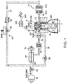
- Fig. 1 is a view illustrating an embodiment of an engine to which a control device of the present disclosure is applied.
- the engine illustrated in this figure is particularly a four-cycle gasoline direct-injection engine mounted on a vehicle, as a propelling source, and includes an engine body 1, an intake passage 30 where intake air introduced into the engine body 1 flows or circulates, an exhaust passage 40 where exhaust gas discharged from the engine body 1 flows or circulates, and an exhaust gas recirculation (EGR) device 50 which recirculates to the intake passage 30 a part of the exhaust gas flowing through the exhaust passage 40.
- EGR exhaust gas recirculation
- the engine body 1 has a cylinder block 3 where cylinders 2 are formed therein, a cylinder head 4 attached to an upper surface of the cylinder block 3 so as to cover up the cylinders 2 from above, and pistons 5 inserted in the respective cylinder 2 so as to reciprocate.
- the engine body 1 is, typically, a multi cylinder type having a plurality of cylinders (e.g., four cylinders lined up in a direction perpendicular to the drawing sheet of Fig. 1 ), one cylinder 2 is focused here for simplifying the description.
- a combustion chamber 6 is defined above the piston 5, and fuel is supplied to the combustion chamber 6 by an injection from an injector 15 (described later). Then, the supplied fuel combusts while being mixed with air inside the combustion chamber 6, and the piston 5 depressed by an expanding force produced by the combustion reciprocates in the vertical direction.
- the fuel injected into the combustion chamber 6 is fuel which contains gasoline as the main component. This fuel may also contain a secondary component, such as bioethanol, in addition to gasoline.
- This injector 15 is capable of injecting the fuel into the combustion chamber 6 in a plurality of steps, as will be described later. This injector 15 is one example of a "fuel injection device" in the present disclosure.
- crankshaft 7 which is an output shaft of the engine body 1 is provided below the piston 5, a crankshaft 7 which is an output shaft of the engine body 1 is provided.
- the crankshaft 7 is coupled to the piston 5 through a connecting rod 8, and is rotated on its center axis in connection with the reciprocating motion (vertical motion, horizontal motion, or inclined motion) of the piston 5.
- a geometric compression ratio of the cylinder 2, i.e., a ratio of a volume of a combustion chamber when the piston 5 is located at a bottom dead center to a volume of the combustion chamber 6 when the piston 5 is located at a top dead center is set as about 13:1 or higher and about 30:1 or lower, as a suitable value for SPCCI combustion (partial compression ignition combustion) described later.
- the geometric compression ratio of the cylinder 2 is preferably set as about 14:1 or higher and about 17:1 or lower in a regular gasoline type which uses gasoline fuel of which the octane number is about 91, and is set about 15:1 or higher and about 18:1 or lower in the high octane type which uses gasoline fuel of which the octane number is about 96.
- the cylinder block 3 is provided with a crank angle sensor SN1 which detects a rotation angle of the crankshaft 7 (crank angle) and a rotating speed of the crankshaft 7 (engine speed).
- the cylinder head 4 is provided with intake ports 9 and exhaust ports 10 which open to the combustion chamber 6, intake valves 11 which open and/or close the intake ports 9, and exhaust valves 12 which open and/or close the exhaust ports 10.
- the valve type of the engine in this embodiment is four-valve type comprised of two intake valves and two exhaust valves, and two intake ports 9, two exhaust ports 10, two intake valves 11, and two exhaust valves 12 are provided to each cylinder 2.
- a swirl valve 18 which can be opened and/or closed is provided to one of the two intake ports 9 connected to one cylinder 2, and the intensity of the swirl flow (a revolving flow which circles around the cylinder axis) inside the cylinder 2 is changed.
- the intake valve 11 and the exhaust valve 12 are opened and/or closed by respective valve operating mechanisms 13 and 14 including a pair of cam shafts disposed in the cylinder head 4 in an interlocked manner with the rotation of the crankshaft 7.
- An intake VVT (Variable Valve Timing) 13a is built inside the valve operating mechanism 13 for the intake valve 11, which is capable of changing at least an open timing of the intake valve 11.
- an exhaust VVT 14a is built inside the valve operating mechanism 14 for the exhaust valve 12, which is capable of changing at least a close timing of the exhaust valve 12.
- a valve overlap period t_VOL which is a period of the valve overlap (a period during which the open period of the intake valve 11 and the open period of the exhaust valve 12 are overlapped with each other) is changed.
- the intake VVT 13a exhaust VVT 14a
- the valve operating mechanism 13 for the intake valve 11 and the valve operating mechanism 14 for the exhaust valve 12 are examples of an "internal EGR amount changing device" in the present disclosure.
- the cylinder head 4 is provided with the injector 15 which injects fuel (mainly gasoline) into the combustion chamber 6, and an ignition plug 16 which ignites a mixture gas comprised of the fuel injected into the combustion chamber 6 from the injector 15 and air introduced into the combustion chamber 6.
- the cylinder head 4 is also provided with an in-cylinder pressure sensor SN2 which detects an in-cylinder pressure which is the pressure inside the combustion chamber 6.
- the injector 15 is an injector of a multiple injection hole type having a plurality of injection holes at a tip-end part thereof, and is capable of injecting fuel radially from the plurality of injection holes.
- the injector 15 is provided so that the tip-end part thereof opposes to a central part of a crown surface of the piston 5. Note that although illustration is omitted, in this embodiment, a cavity is formed in the crown surface of the piston 5, where a comparatively large area including the central part is dented to the opposite side (downward) from the cylinder head 4.
- the ignition plug 16 is disposed at a position slightly offset from the injector 15 to the intake side.
- the ignition plug 16 corresponds to an "ignition device" in the present disclosure.
- the intake passage 30 is connected to one side surface of the cylinder head 4 so as to communicate with the intake ports 9. Air (fresh air) taken in from an upstream end of the intake passage 30 is introduced into the combustion chamber 6 through the intake passage 30 and the intake ports 9.
- the intake passage 30 is provided with an air cleaner 31 which removes foreign substances in intake air, a throttle valve 32 which can be opened and/or closed to adjust a flow rate of the intake air, a supercharger 33 which pumps the intake air while compressing the intake air, an intercooler 35 which cools the intake air compressed by the supercharger 33, and a surge tank 36, in this order from the upstream side.
- an air cleaner 31 which removes foreign substances in intake air
- a throttle valve 32 which can be opened and/or closed to adjust a flow rate of the intake air
- a supercharger 33 which pumps the intake air while compressing the intake air
- an intercooler 35 which cools the intake air compressed by the supercharger 33
- a surge tank 36 in this order from the upstream side.
- An airflow sensor SN3 which detects a flow rate of intake air
- an intake air temperature sensor SN4 which detects the temperature of the intake air
- an intake pressure sensor SN5 which detects the pressure of the intake air are provided to respective parts of the intake passage 30.
- the airflow sensor SN3 and the intake air temperature sensor SN4 are provided to a part of the intake passage 30 between the air cleaner 31 and the throttle valve 32, and detect the flow rate and the temperature of intake air which passes through this part.
- the intake pressure sensor SN5 is provided to the surge tank 36, and detects the pressure of intake air inside the surge tank 36.
- the supercharger 33 is a mechanical supercharger which is mechanically coupled to the engine body 1.
- the type of the supercharger 33 may be any types, and, for example, any one of known superchargers, such as a Lysholm type, a Root type, and a centrifugal type, may be used as the supercharger 33.
- an electromagnetic clutch 34 which is capable of electrically switching between engage and disengage is provided.
- the electromagnetic clutch 34 is engaged, the driving force is transmitted to the supercharger 33 from the engine body 1, and boosting of the supercharger 33 is performed.
- the electromagnetic clutch 34 is disengaged, the transmission of the driving force is intercepted, and the boosting of the supercharger 33 is suspended.
- a bypass passage 38 for bypassing the supercharger 33 is provided to the intake passage 30.
- the bypass passage 38 connects the surge tank 36 with an EGR passage 51 (described later).
- a bypass valve 39 which can be opened and/or closed is provided to the bypass passage 38.
- the bypass valve 39 is a valve for adjusting the pressure of intake air introduced into the surge tank 36 (i.e., boosting pressure). For example, as the opening of the bypass valve 39 increases, a flow rate of intake air which flows backwards to the upstream side of the supercharger 33 through the bypass passage 38 increase, and, as a result, the boosting pressure is lowered.
- the exhaust passage 40 is connected to the other side surface of the cylinder head 4 so as to communicate with the exhaust ports 10. Burnt gas generated inside the combustion chamber 6 (exhaust gas) is discharged outside through the exhaust ports 10 and the exhaust passage 40.
- a catalytic converter 41 is provided to the exhaust passage 40.
- a three-way catalyst 41a and a GPF (Gasoline Particulate Filter) 41b are built inside the catalytic converter 41, in this order from the upstream side.
- the EGR device 50 has the EGR passage 51 which communicates the exhaust passage 40 with the intake passage 30, and an EGR cooler 52 and an EGR valve 53 provided to the EGR passage 51.
- the EGR passage 51 connects a part of the exhaust passage 40 downstream of the catalytic converter 41 with a part of the intake passage 30 between the throttle valve 32 and the supercharger 33.
- the EGR cooler 52 cools, by heat exchange, external EGR gas which is exhaust gas recirculated from the exhaust passage 40 to the intake passage 30 through the EGR passage 51.
- the EGR valve 53 is provided to the EGR passage 51 downstream of the EGR cooler 52 (closer to the intake passage 30) so as to be openable and/or closable, and adjusts a flow rate of exhaust gas which flows in circulates the EGR passage 51.
- a pressure difference sensor SN6 which detects a difference between the pressure upstream of the EGR valve 53 and the pressure downstream of the EGR valve 53 is provided to the EGR passage 51.
- FIG. 3 is a block diagram illustrating a control system of the engine.
- An ECU (electronic control unit) 100 illustrated in this figure is a microcontroller for comprehensively controlling the engine, and is comprised of a processor 101 (e.g., a central processing unit (CPU)) having associated ROM and RAM, etc., which are well known in the art.
- processor 101 e.g., a central processing unit (CPU)
- CPU central processing unit
- Detection signals of various sensors are inputted into the ECU 100.
- the ECU 100 is electrically connected to the crank angle sensor SN1, the in-cylinder pressure sensor SN2, the airflow sensor SN3, the intake air temperature sensor SN4, the intake pressure sensor SN5, and the pressure difference sensor SN6, which are described above.
- Information detected by these sensors such as a crank angle, an engine speed, an in-cylinder pressure, an intake air flow rate, an intake air temperature, an intake pressure, and a pressure difference between locations before and after the EGR valve 53, are sequentially inputted into the ECU 100.
- an accelerator sensor SN7 which detects an opening of an accelerator pedal operated by a driver who operates the vehicle is provided to the vehicle. A detection signal of the accelerator sensor SN7 is also inputted into the ECU 100.
- the ECU 100 controls each part of the engine, while performing various determinations, calculations, etc. based on the input signals from the sensors. That is, the ECU 100 is electrically connected to the intake VVT 13a, the exhaust VVT 14a, the injector 15, the ignition plug 16, the swirl valve 18, the throttle valve 32, the electromagnetic clutch 34, the bypass valve 39, the EGR valve 53, etc., and outputs control signals to these devices based on the results of the calculation, etc.
- This ECU 100 is an example of a "controller" in the present disclosure.
- Fig. 4 is a map illustrating a difference of the control according to the engine speed and the engine load.
- an engine operating range is divided into two or more operating ranges. Particularly, the engine operating range is roughly divided into three operating ranges A1, A2, and B.
- the first operating range A1 is particularly a low-speed low-load range where the engine speed is lower than a given reference speed N1 and the engine load is lower than a given reference load T1
- the second operating range A2 is particularly a low-speed high-load range where the engine speed is lower than the reference speed N1 and the engine load is the reference load T1 or higher
- the third operating range B is particularly a high-speed range where the engine speed is the reference speed N1 or higher.
- the ECU 100 determines which operating range among the first to third operating ranges A1-B the present operation point falls based on the engine speed and the engine load which are detected by the crank angle sensor SN1, and carries out a control described below. Note that the ECU 100 calculates the engine load based on the opening of the accelerator pedal detected by the accelerator sensor SN7, the engine speed, etc.
- SPCCI combustion compression ignition combustion in which spark ignition (SI) combustion and compression ignition (CI) combustion are mixed (hereinafter, referred to as "SPCCI combustion") is performed. Note that “SPCCI” in SPCCI combustion is an abbreviation for "SPark Controlled Compression Ignition.”
- SI combustion is a combustion mode in which the mixture gas is ignited by the ignition plug 16 and the mixture gas is forcibly combusted by flame propagation which extends its combustion range from an igniting point to the perimeter.
- CI combustion is a combustion mode in which the mixture gas is combusted by self-ignition under a high-temperature and high-pressure environment which is created according to compression by the piston 5.
- SPCCI combustion in which SI combustion and CI combustion are mixed is a combustion mode in which SI combustion of a portion of the mixture gas inside the combustion chamber 6 is carried out by a jump-spark ignition which is performed under an environment just before the mixture gas self-ignites, and CI combustion of the remaining mixture gas inside the combustion chamber 6 is carried out by self-ignition after the SI combustion (by a further increase in the temperature and the pressure accompanying the SI combustion).
- Fig. 5 is a graph illustrating a change in the rate of heat release (J/deg) with respect to the crank angle when SPCCI combustion occurs.
- the heat release during SI combustion becomes lower than the heat release during CI combustion.
- a pressure fluctuation in the combustion chamber 6 i.e., dP/d ⁇ , where P is an in-cylinder pressure and ⁇ is a crank angle
- dP/d ⁇ a pressure fluctuation in the combustion chamber 6
- the waveform of the rate of heat release during SPCCI combustion is formed so that a first heat release rate part (a part illustrated by Q1) where a rising slope formed by SI combustion is relatively shallow, and a second heat release rate part (a part illustrated by Q2) where the rising slope formed by CI combustion is relatively steep, are continuous in this order.
- the slope of the waveform of the rate of heat release changes from shallow to steep at the timing of this self-ignition (i.e., the timing at which CI combustion starts). That is, the waveform of the rate of heat release during SPCCI combustion has a point of inflection (indicated by an "X" in Fig. 5 ) which appears at a timing ⁇ ci where CI combustion starts.
- SI combustion and CI combustion are performed in parallel.
- the rate of heat release becomes relatively high.
- the slope of the waveform of the rate of heat release will not become excessive. That is, since the motoring pressure falls by the descent of the piston 5 after the compression top dead center, this suppresses the rise of the rate of heat release, and, as a result, dP/d ⁇ during CI combustion is avoided from becoming excessive.
- dP/d ⁇ used as the index of combustion noise is unlikely to become excessive because of the nature of CI combustion being performed after SI combustion, and combustion noise can be reduced compared with simple CI combustion (when CI combustion of all the fuel is carried out).
- the air-fuel ratio (A/F) inside the combustion chamber 6 is made higher (leaner) than a stoichiometric air-fuel ratio, in order to improve fuel efficiency.
- the air-fuel ratio inside the combustion chamber 6 is increased so that an amount of raw NO x which is NO x generated inside the combustion chamber 6 becomes small enough.
- the air-fuel ratio inside the combustion chamber 6 is made to about 30:1.
- the injector 15 injects into the combustion chamber 6 such an amount of fuel that the air-fuel ratio (A/F) inside the combustion chamber 6 becomes the high value as described above.
- the injector 15 is driven so that the entire amount of fuel to be supplied to the combustion chamber 6 in one cycle is injected into the combustion chamber 6 in an intake stroke. For example, the entire amount of fuel is injected into the first half of an intake stroke.
- the throttle valve 32 is fully opened.
- the ignition plug 16 ignites the mixture gas near a compression top dead center. SPCCI combustion starts triggered by this ignition, a portion of the mixture gas inside the combustion chamber 6 combusts by flame propagation (SI combustion), and the remaining mixture gas then combusts by self-ignition (CI combustion).
- SI combustion flame propagation
- CI combustion self-ignition
- the opening of the EGR valve 53 is particularly controlled so that a target external EGR rate which is a target value of the external EGR rate becomes larger as the engine load increases.
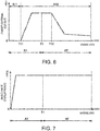
- Fig. 6 is a graph illustrating a relationship between the engine load and/or the target external EGR rate when the engine speed becomes a given engine speed N10 (see Fig. 4 ) lower than the reference speed N1.
- the target external EGR rate is particularly set to about zero in a partial range of the first operating range A1 where the engine load is below a given first load T11. Therefore, in this partial range, the EGR valve 53 is closed, and the introduction of the external EGR gas into the combustion chamber 6 is suspended.
- the target external EGR rate is set to a value larger than zero in a partial range of the first operating range A1 where the engine load is the first load T11 or higher.
- the intake VVT 13a and the exhaust VVT 14a particularly set the open timings and the close timings (i.e., these are comprehensively referred to as "the open-and-close timing(s)") of the intake valve 11 and the exhaust valve 12 at timings where the valve overlap in which the open period of the intake valve 11 and the open period of the exhaust valve 12 overlap with each other occurs.
- these open-and-close timings are set so that both the intake valve 11 and the exhaust valve 12 are opened over an exhaust top dead center (TDC).
- the intake and exhaust valves 11 and 12 are opened and/or closed so as to achieve the valve overlap, the internal EGR where hot burnt gas remains in the combustion chamber 6 is realized.
- Fig. 7 is a graph illustrating a relationship between the engine load and the valve overlap period t_VOL when the engine speed becomes the given speed N10.
- the valve overlap period t_VOL is particularly set to a comparatively large value and is kept substantially constant regardless of the engine load in other ranges.
- the valve overlap period t_VOL is set to substantially zero.
- the open timing of the intake valve 11 is set to about 30°CA (crank angle) before a compression top dead center (TDC)
- the close timing of the exhaust valve 12 is set to about 30°CA after the compression top dead center
- the valve overlap period t_VOL is set to about 60°CA at the most.
- the swirl valve 18 In the first operating range A1, the swirl valve 18 is fully closed or closed to a narrow opening which is near fully closed. Therefore, a strong swirl flow is formed inside the combustion chamber 6.
- the supercharger 33 is particularly suspended at the lower engine speed side in the first operating range A1. That is, the electromagnetic clutch 34 is disengaged to release the coupling of the supercharger 33 to the engine body 1, and particularly by fully opening the bypass valve 39, the boosting of the supercharger 33 is suspended.
- the supercharger 33 operates at the higher engine speed side in the first operating range A1. That is, the boosting of the supercharger 33 is performed by engaging the electromagnetic clutch 34 to couple the supercharger 33 to the engine body 1.
- the opening of the bypass valve 39 is controlled so that the pressure inside the surge tank 36 detected by the intake pressure sensor SN5 (boosting pressure) becomes in agreement with the target pressure defined beforehand for every operating condition (the engine speed and the engine load).
- the second operating range A2 is particulrly a range where the engine load is higher and the amount of fuel supplied to the combustion chamber 6 is larger than those in the first operating range A1. Therefore, in the second operating range A2, it becomes difficult to increase the air-fuel ratio inside the combustion chamber 6. For this reason, in the second operating range A2, the air-fuel ratio inside the combustion chamber 6 is set to near a stoichiometric air-fuel ratio.
- the injector 15 injects into the combustion chamber 6 such an amount of fuel that the air-fuel ratio becomes near the stoichiometric air-fuel ratio as described above.
- the large portion of the fuel to be injected into one cycle is injected in an intake stroke, and the remaining fuel is injected in a compression stroke.
- the throttle valve 32 is fully opened.
- the ignition plug 16 ignites the mixture gas near the compression top dead center. Also in the second operating range A2, SPCCI combustion is started triggered by this ignition, the portion of the mixture gas inside the combustion chamber 6 combusts by flame propagation (SI combustion), and the remaining mixture gas then combusts by a self-ignition (CI combustion).
- SI combustion flame propagation
- CI combustion self-ignition
- the opening of the EGR valve 53 is controlled so that the amount of external EGR gas introduced into the combustion chamber 6 decreases as the load increases.
- the target external EGR rate is set to a value equivalent to the maximum value in the first operating range A1. Therefore, in this partial range, the opening of the EGR valve 53 is made comparatively large to introduce a large amount of external EGR gas into the combustion chamber 6.
- the target external EGR rate is made smaller as the engine load increases.
- the target external EGR rate is set to a value larger than zero in the entire second operating range A2, and the EGR valve 53 is opened in the entire second operating range A2.
- the target external EGR rate is set to about 30% at the lower load side in the second operating range A2, and the target external EGR rate is set to about 10% at the operation point of the second operating range A2 where the engine load becomes the maximum.
- the EGR valve 53 in a range A where SPCCI combustion is carried out, the EGR valve 53 is closed in a range A11 where the engine load is lower than the first load T11.
- the EGR valve 53 is opened in a range A12 where the engine load is the first load T11 or higher.
- the range including the first operating range A1 and the second operating range A2 where SPCCI combustion is carried out is suitably referred to as the "SPCCI range A.”
- a partial range of the SPCCI range A where the engine load is the first load T11 or higher and the EGR valve 53 is opened is referred to as the “EGR open range A12.”
- the first load T11 is an example of a “given value” in the present disclosure
- the EGR open range A12 is an example of a "high-load range” in the present disclosure.
- the open-and-close timings of the intake valve 11 and the exhaust valve 12 are set as timings at which the valve overlap in which the open period of the intake valve 11 and the open period of the exhaust valve 12 overlap with each other occurs.
- such open-and-close timings are set so that both the intake valve 11 and the exhaust valve 12 are opened over the exhaust top dead center.
- the open timing of the intake valve 11 and the close timing of the exhaust valve 12 are substantially fixed, regardless of the engine load, and therefore, as illustrated in Fig. 7 , the valve overlap period t_VOL is kept substantially constant, regardless of the engine load.
- the valve overlap period t_VOL in the second operating range A2 is set to a value substantially the same as the maximum value of the valve overlap period t_VOL in the first operating range A1 (e.g., about 60°CA).
- the internal EGR where hot burnt gas remains inside the combustion chamber 6 is realized by opening and/or closing the intake and exhaust valves 11 and 12 so that the valve overlap is produced, similar to the first operating range A1.
- the swirl valve 18 is opened to a suitable intermediate opening other than fully closed and fully opened, and the opening is made larger as the engine load increases.
- the supercharger 33 is suspended at a side of the second operating range A2 where both the engine speed and the engine load are low. On the other hand, the supercharger 33 operates in other ranges in the second operating range A2.
- the injector 15 injects fuel over a given period of time which at least overlaps with an intake stroke.
- the ignition plug 16 ignites the mixture gas near the compression top dead center.
- SI combustion is started triggered by this ignition, and the entire mixture gas inside the combustion chamber 6 combusts by flame propagation.
- the supercharger 33 operates. Particularly, the throttle valve 32 is fully opened.
- the valve opening of the EGR valve 53 is controlled so that the air-fuel ratio (A/F) inside the combustion chamber 6 becomes a stoichiometric air-fuel ratio or slightly richer (or smaller) than the stoichiometric air-fuel ratio.
- a gas-fuel ratio inside the combustion chamber 6 G/F: the total gas mass inside the combustion chamber 6 to a fuel mass
- the swirl valve 18 is fully opened.
- the contents described in the above section (3-1) are the contents of the control when the steady operation is performed in the first operating range A1 and the second operating range A2, i.e., when each parameter is stable.
- a control when a torque down request is issued in the range where SPCCI combustion is carried out particularly including the first operating range A1 and the second operating range A2 (hereinafter, suitably referred to as the "SPCCI range A") and the engine load is reduced is described.
- the torque down request is issued to the ECU 100, for example, from a transmission 60 (see Fig. 3 ) provided to the vehicle, particularly from an ECU configured to controll the transmission 60.
- the engine body 1 is mounted on the vehicle provided with the transmission 60 of a multi-stage (multi-speed) type which particularly reduces or increse the rotation of the engine body 1 (or the engine speed) and transmits the reduced or incresed rotation to the wheels.
- a multi-stage (multi-speed) type which particularly reduces or increse the rotation of the engine body 1 (or the engine speed) and transmits the reduced or incresed rotation to the wheels.
- a control device for gear change which controls the transmission 60 (not illustrated) and an operating mechanism, such as a shift lever which allows a driver of the vehicle to operate the transmission 60 are mounted on the vehicle.
- the control device for gear change determines that there is a request for an upshift, and instructs the ECU 100 to reduce the engine torque.
- the ECU 100 determines that there is the torque down request. Note that the timing of issuing the torque down request is not limited to when the upshift is requested. For example, in a vehicle provided with a traction control system for preventing a wheel slip, this system requests the torque down to the ECU 100 in order to prevent the wheel slip. Moreover, it may be determined that the torque down is requested also when there is a slowdown of the vehicle.
- the target external EGR rate is changed according to the engine load, and the EGR valve 53 is driven so as to realize the target external EGR rate.
- the EGR valve 53 is driven so as to realize the target external EGR rate.
- there is a response delay in the EGR valve 53 That is, it takes time for the opening of the EGR valve 53 to actually be changed by the instructed opening after the ECU 100 instructs the opening change to the EGR valve 53.
- the external EGR gas is introduced into the combustion chamber 6 through the exhaust passage 40, the EGR passage 51, and the intake passage 30, and therefore, even if the flow rate of exhaust gas inside the exhaust passage 40 changes with the change in the engine load, and even if the opening of the EGR valve 53 changes, it takes time for the amount of external EGR gas introduced into the combustion chamber 6 to be changed.
- the fuel injected into the combustion chamber 6 in the second half of the compression stroke since the pressure inside the combustion chamber 6 is high and the time up to compression top dead center is short, the fuel may or will not be diffused throughout the combustion chamber 6, and stays at the center of the combustion chamber 6. Therefore, if the fuel is injected into the combustion chamber 6 in the second half of the compression stroke, a rich mixture gas with a high air-fuel ratio (A/F: a ratio of the mass A of air to the mass F of the fuel inside the combustion chamber 6) can be formed inside the combustion chamber 6.
- A/F a rich mixture gas with a high air-fuel ratio
- the injector 15 and the ignition plug 16 are disposed at positions comparatively close to each other, and the rich mixture gas is formed around the ignition plug 16.
- the rich mixture gas is formed inside the combustion chamber 6 near a compression top dead center, this mixture gas can be securely combusted by ignition energy given from the ignition plug 16.
- the temperature inside the combustion chamber 6 can be raised, and the remaining mixture gas can also be appropriately self-ignited. That is, SPCCI combustion of the mixture gas can be appropriately carried out.
- Figs. 8A and 8B are particularly views illustrating patterns of the fuel injection in the first operating range A1, where Fig. 8A is an injection pattern during a steady operation, and Fig. 8B is an injection pattern during the torque down.
- Fig. 8A in the first operating range A1, all of the fuel to be injected into one cycle into the combustion chamber 6 is injected (M1) in an intake stroke during the steady operation, as described above.
- the fuel injection (M1) carried out in the intake stroke is an example of a "first injection” in the present disclosure
- the fuel injection (M2) carried out in the second half of the compression stroke is an example of a "second injection” in the present disclosure.
- Figs. 9A and 9B are particularly views illustrating patterns of the fuel injection in the second operating range A2, where Fig. 9A is an injection pattern during the steady operation, and Fig. 9B is an injection pattern during the torque down.
- Fig. 9A in the second operating range A2, during the steady operation, a large portion of the fuel to be injected into one cycle into the combustion chamber 6 is injected (M11) in an intake stroke, and the remaining fuel is injected (M12) particularly in the first half of a compression stroke, as described above.
- M11 the fuel to be injected into one cycle into the combustion chamber 6
- M12 particularly in the first half of a compression stroke
- a portion of the fuel to be injected into one cycle into the combustion chamber 6 is injected (M11) in the intake stroke, a portion of the remaining fuel is injected (M12) particularly in the first half of the compression stroke, and the remaining fuel is injected (M13) particularly in the second half of the compression stroke.
- the fuel injection (M11) carried out in the intake stroke and the fuel injection (M12) carried out in the first half of the compression stroke are another example of the "first injection” in the present disclosure
- the fuel injection (M13) carried out in the second half of the compression stroke is another example of the "second injection” in the present disclosure.
- the fuel injection (M2 or M13) carried out in the second half of a compression stroke is suitably referred to as an "additional injection.”
- the entire amount of fuel to be supplied into the combustion chamber 6 in one combustion cycle is injected in a period from an intake stroke to the first half of a compression stroke, and the additional injection in which fuel is injected into the combustion chamber 6 in the second half of the compression stroke is stopped.
- this additional injection is carried out, and a ratio of the amount of fuel injected into the combustion chamber 6 by the additional injection to the total amount of fuel to be supplied to the combustion chamber 6 in one combustion cycle is increased from zero.
- the ratio of the amount of fuel injected into the combustion chamber 6 by the additional injection to the total amount of fuel to be supplied to the combustion chamber 6 in one combustion cycle is increased to be more than a ratio (e.g. zero) of the amount of fuel injected into the combustion chamber 6 by the additional injection to the total amount of fuel to be supplied to the combustion chamber 6 in one combustion cycle when no torque down is issued.
- the amount of fuel injected into the combustion chamber 6 in one combustion cycle is maintained constant when carrying out and not carrying out the additional injection, the amount of fuel for the additional injection is increased, and therefore, the amount of fuel for the fuel injection which is carried out before the additional injection is reduced because of the additional injection.
- the amount of fuel injected into the combustion chamber 6 by the fuel injection (M1) carried out in the intake stroke is reduced because of the additional injection (M2).
- the amount of fuel injected into the combustion chamber 6 by the fuel injections (M11 and M12) carried out in the intake stroke and the first half of the compression stroke is reduced because of the additional injection (M13).
- the valve overlap period t_VOL of the intake valve 11 and the exhaust valve 12 is particularly made smaller than the value during the steady operation. If the valve overlap period t_VOL of the intake valve 11 and the exhaust valve 12 is made smaller, the amount of internal EGR gas that remains inside the combustion chamber 6 (i.e., inactive gas) becomes smaller. Therefore, combustion of the mixture gas inside the combustion chamber 6 is stimulated.
- the valve overlap is realized by opening the intake valve 11 and the exhaust valve 12 over the exhaust top dead center, as described above. Therefore, if this valve overlap period t_VOL becomes smaller, the amount of burnt gas that returns to the combustion chamber 6 after being drawn into the intake passage 30 and the exhaust passage 40 decreases, and therefore, the amount of internal EGR gas is effectively reduced.
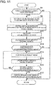
- the ECU 100 determines at Step S1 whether the torque down request is issued during the operation in the EGR open range A12. The ECU 100 determines whether the engine is operated in the EGR open range A12 based on the engine speed and the engine load. Moreover, as described above, when a command signal of the torque down request is received from the transmission control device, the ECU 100 determines that the torque down request is issued.
- Step S2 the ECU 100 calculates a destination of the operation point (destinations of the engine speed and the engine load) in connection with the reduction of the engine torque in response to the torque down request, and sets a target value and a basic value of each parameter at the destination of the operation point.
- the ECU 100 sets a target external EGR rate, a basic EGR valve opening, a basic ignition timing, intake basic open-and-close timings, and exhaust basic open-and-close timings at the destination of the operation point.
- the target external EGR rate is a target value of the external EGR rate during the steady operation (i.e., when the engine body 1 is operated steadily), and it is set like the graph of Fig. 6 when the engine speed is the given speed N10.
- the target external EGR rate is set beforehand corresponding to each engine speed and each engine load, and the target external EGR rate are stored in the ECU 100 in the form of a map.
- the ECU 100 extracts the target external EGR rate corresponding to the destinations of the engine speed and the engine load from this map.
- the basic EGR valve opening is a basic value of the opening of the EGR valve 53.
- the basic EGR valve opening is an opening of the EGR valve 53 at which the target external EGR rate described above is realized fundamentally during the steady operation.
- the basic EGR valve opening is set beforehand corresponding to each engine speed and each engine load, and the target external EGR rate are stored in the ECU 100 in the form of a map.
- the ECU 100 extracts the basic EGR valve opening corresponding to the destinations of the engine speed and the engine load from this map.
- the basic ignition timing is an ignition timing during the steady operation.
- the basic ignition timing is set beforehand corresponding to each engine speed and each engine load, and the basic ignition timings are stored in the ECU 100 in the form of a map.
- the ECU 100 extracts the basic ignition timing corresponding to the destinations of the engine speed and the engine load from this map.
- the intake basic open-and-close timings are basic values of the open-and-close timings (the open timing and the close timing) of the intake valve 11.
- the exhaust basic open-and-close timings are basic values of the open-and-close timings (the open timing and the close timing) of the exhaust valve 12.
- the intake basic open-and-close timings and the exhaust basic open-and-close timing are open-and-close timings of the intake valve 11 and the exhaust valve 12 during the steady operation, and a basic overlap period which is a valve overlap period when these intake basic open-and-close timings and exhaust basic open-and-close timing are realized is set so as to become the graph of Fig. 7 at the given engine speed N10.
- the intake basic open-and-close timings and the exhaust basic open-and-close timings are set beforehand corresponding to each engine speed and each engine load, and the intake basic open-and-close timings and the exhaust basic open-and-close timings are stored in the ECU 100 in the form of a map.
- the ECU 100 extracts the intake basic open-and-close timings and the exhaust basic open-and-close timings corresponding to the destinations of the engine speed and the engine load from the respective maps.
- Step S3 the ECU 100 sets the opening of the EGR valve 53 to the basic EGR valve opening set at Step S2, and drives the intake VVT 13a and the exhaust VVT 14a so that the open-and-close timings of the intake valve 11 and the exhaust valve 12 become the intake basic open-and-close timings and the exhaust basic open-and-close timings which are set at Step S2, respectively.
- Step S4 the process shifts to Step S4.
- the ECU 100 determines whether the target external EGR rate is reduced.
- the ECU 100 calculates a target external EGR rate reducing amount which is a target value of the reducing amount of the external EGR rate (a value of the external EGR rate to be reduced) by subtracting the target exterior EGR at the destination of the operation point calculated at Step S2 from the target external EGR rate when the torque down request is issued.
- Step S5 the ECU 100 determines whether the target external EGR rate reducing amount calculated at Step S4 is larger than a given determination reducing amount.
- the determination reducing amount is set beforehand and stored in the ECU 100. In this embodiment, the determination reducing amount is set as zero.
- Step S5 If the determination at Step S5 is NO and the target external EGR rate reducing amount is below the determination reducing amount, the process ends without carrying out the additional injection (it returns to Step S1).
- Step S5 determines whether the target external EGR rate reducing amount is larger than the determination reducing amount. If the determination at Step S5 is YES and the target external EGR rate reducing amount is larger than the determination reducing amount, it shifts to Step S6. At Step S6, the ECU 100 carries out the additional injection.
- the basic EGR valve opening when the target external EGR rate decreases, the basic EGR valve opening also decreases (the opening becomes the closing side). Therefore, if the determination at Step S5 becomes YES and the target external EGR rate reducing amount is larger than the determination reducing amount, the basic EGR valve opening was set as the opening at the closing side at Step S2, and in connection with this, the opening of the EGR valve 53 is also changed to an opening at the closing side at Step S3. That is, in this embodiment, if the determination at Step S5 is YES and the target external EGR rate reducing amount is larger than the determination reducing amount, the opening of the EGR valve 53 is reduced.
- Step S7 the ECU 100 determines whether the elapsed time after the torque down request is issued is more than a given determination time.
- This determination time is set beforehand and stored in the ECU 100. For example, this determination time is set as about 0.2 seconds.
- Step S7 If the determination at Step S7 is YES and the elapsed time after the torque down request is issued is more than the determination time, it shifts to Step S8.
- Step S8 the ECU 100 suspends the additional injection and ends this process (it returns to Step S1).
- Step S7 determines whether the elapsed time after the torque down request is issued is below the determination time. If the determination at Step S7 is NO and the elapsed time after the torque down request is issued is below the determination time, it returns to Step S6. That is, the ECU 100 repeats Step S6 until the elapsed time after the torque down request is issued becomes more than the determination time to continue the additional injection.
- the additional injection is carried out. Then, the additional injection is continued after the torque down request is issued until the determination time elapses.
- the ECU 100 carries out Step S11 and the subsequent steps illustrated in Fig. 11 , after carrying out Steps S1-S3.
- the ECU 100 calculates at Step S11 an actual external EGR rate which is the present external EGR rate.
- the ECU 100 estimates the present external EGR rate based on the present opening of the EGR valve 53, the present detection value of the pressure difference sensor SN6, the present detection value of the airflow sensor SN3, the present open-and-close timings of the intake valve 11 and the exhaust valve 12, etc.
- Step S12 the ECU 100 calculates an excessive amount of the actual external EGR rate with respect to the target external EGR rate by subtracting the target external EGR rate at the destination set at Step S1 from the actual external EGR rate calculated at Step S11.
- this excessive amount is suitably referred to as the "external EGR rate excessive amount.”
- Step S13 the ECU 100 determines whether the external EGR rate excessive amount calculated at Step S12 is larger than a given first determination excessive amount.
- the first determination excessive amount is set beforehand and stored in the ECU 100.
- Step S13 If the determination at Step S13 is NO and the external EGR rate excessive amount is below the first determination excessive amount, the process ends (it returns to Step 1).
- Step S13 determines whether the determination at Step S13 is YES and the external EGR rate excessive amount is larger than the first determination excessive amount.
- Step S14 the ECU 100 drives the intake VVT 13a and the exhaust VVT 14a so that the valve overlap period of the intake valve 11 and the exhaust valve 12 becomes shorter than the basic overlap period corresponding to the intake basic open-and-close timings and the exhaust basic open-and-close timings which are set at Step S2.
- the ECU 100 drives the exhaust VVT 14a so that the close timing of the exhaust valve 12 becomes a timing on the advancing side of the exhaust basic open-and-close timings (in other words, the exhaust basic close timing), and drives the intake VVT 13a so that the open timing of the intake valve 11 becomes a timing on the retarding side of the intake basic open-and-close timing (in other words, the intake basic open timing).
- the advancing amount of the close timing of the exhaust valve 12 and the retarding amount of the open timing of the intake valve 11 are the same amount.
- the advancing amount and the retarding amount are increased as the external EGR rate excessive amount becomes larger and the reducing amount of the valve overlap period becomes larger.
- Step S15 the ECU 100 updates the external EGR rate excessive amount. That is, the ECU 100 again calculates the present actual external EGR rate, and calculates the latest external EGR rate excessive amount by subtracting the target external EGR rate set at Step S2 from the newly calculated actual external EGR rate.
- Step S16 the ECU 100 determines whether the external EGR rate excessive amount is smaller than a second determination excessive amount set beforehand.
- the second determination excessive amount is set as the same value as the first determination excessive amount. Note that the second determination excessive amount may be a value smaller than the first determination excessive amount.
- Step S16 If the determination at Step S16 is YES, and the external EGR rate excessive amount becomes below the second determination excessive amount, it shifts to Step S17.
- Step S17 the ECU 100 resumes the open-and-close timings of the intake valve 11 and the exhaust valve 12 to the basic open-and-close timings, and then ends this process (it returns to Step S1).
- Step S16 determines whether the external EGR rate excessive amount is still above the second determination excessive amount. If the determination at Step S16 is NO and the external EGR rate excessive amount is still above the second determination excessive amount, it returns to Step S14. That is, the ECU 100 maintains the valve overlap period of the intake valve 11 and the exhaust valve 12 at a value smaller than the basic overlap period, until the external EGR rate excessive amount becomes smaller than the second determination excessive amount.
- the additional injection is carried out, and if the external EGR rate excessive amount at this time is larger than the first determination excessive amount, the valve overlap period of the intake valve 11 and the exhaust valve 12 is made smaller than the value during the steady operation (the basic overlap period). Then, when the determination time elapses after the torque down request is issued, the additional injection is suspended, and if the external EGR rate excessive amount becomes below the second determination excessive amount, the valve overlap period of the intake valve 11 and the exhaust valve 12 is resumed to the value during the steady operation (the basic overlap period).
- Fig. 12 is a view illustrating a temporal change in each parameter when performing the control according to this embodiment.
- This figure illustrates graphs of a vehicle speed, a gear stage, a valve opening of the throttle valve 32, a filling amount, the external EGR rate, an additional injection execution flag, and the valve overlap period, in this order from the top.
- the filling amount is an amount of air introduced into the combustion chamber 6, and is a parameter corresponding to the engine load.
- the additional injection execution flag is a parameter which becomes 1 when the additional injection is carried out, and becomes 0 when the additional injection is suspended.
- a broken line is the target external EGR rate
- a solid line is the actual external EGR rate.
- the throttle valve 32 When the gear stage is made neutral and the torque down request is issued from the transmission control device in order to upshift at a time t1 (i.e., when the engine load falls to near zero), the throttle valve 32 is closed to near the fully close, and therefore, the filling amount drops. Moreover, after the time t1, the target external EGR rate falls with the fall of the engine load. However, as described above, the amount of external EGR gas introduced into the combustion chamber 6 does not decrease immediately, and the actual external EGR rate becomes larger than the target external EGR rate from the time t1 to a time t2.
- the rich mixture gas with the low air-fuel ratio can be formed inside the combustion chamber 6 by the additional injection, and the combustion of the mixture gas can be started more securely.
- the ignition energy is effectively supplied to this mixture gas, and the combustion of the mixture gas begins securely.
- the temperature inside the combustion chamber 6 can be increased by the combustion of the mixture gas and self-ignition combustion of the remaining mixture gas can be carried out appropriately.
- the combustion can be prevented from becoming unstable, and the suitable SPCCI combustion can be realized more securely.
- valve overlap period is made smaller than the basic overlap period illustrated by the broken line.
- the valve overlap period When the valve overlap period is shortened, the internal EGR amount which is the inactive gas remaining in the combustion chamber 6 is reduced, as described above. Therefore, according to this embodiment, the inactive gas can be prevented from impeding the combustion of the mixture gas, and combustion stability can be further improved.
- combustion stability can be improved more securely when the torque down request is issued.
- fuel efficiency can be improved, and combustion stability can be improved while reducing the engine torque at an early stage.
- a method of delaying a closing speed of the throttle valve 32 as illustrated by a one-dot chain line in the graph of the throttle valve 32 of Fig. 12 there may be a method of delaying a closing speed of the throttle valve 32 as illustrated by a one-dot chain line in the graph of the throttle valve 32 of Fig. 12 . That is, when the closing speed of the throttle valve 32 is slowed down, a decreasing speed of the amount of air introduced into the combustion chamber 6 can be slowed down. Therefore, the ratio of the mass of the burnt gas (including the external EGR gas and the internal EGR gas) inside the combustion chamber 6 to the air amount can be prevented from becoming excessive, thereby preventing the deterioration of combustion stability.
- the ignition timing may be retarded additionally. That is, when the closing speed of the throttle valve 32 is slowed down to slow down the decreasing speed of the amount of air introduced into the combustion chamber 6, and the ignition timing is retarded, the engine torque can be reduced while preventing the deterioration of combustion stability.
- the combustion period of the mixture gas is retarded by the retarding of the ignition timing, fuel efficiency is deteriorated.
- the additional injection when the request for reducing the amount of external EGR gas introduced into the combustion chamber 6 is issued, the additional injection is carried out, regardless of the amount of engine torque to be reduced when the torque down request is issued, the additional injection may be carried out only when the amount of engine torque to be reduced is more than a given value.
- the mass of the external EGR gas to be introduced into the combustion chamber 6 may be calculated, and when this mass falls, it may be determined that the request is issued.
- the additional injection is carried out to inject fuel in the second half of a compression stroke, the fuel may be injected into the second half of the compression stroke in other situations.
- the ratio of fuel injected into the combustion chamber 6 by the additional injection to the total amount of fuel injected into the combustion chamber 6 in one combustion cycle is increased than the air-fuel ratio when there is not the request, and when there is the request, the mixture gas in which the air-fuel ratio is further richer (lower) is formed inside the combustion chamber 6.
Landscapes
- Engineering & Computer Science (AREA)
- Chemical & Material Sciences (AREA)
- Combustion & Propulsion (AREA)
- Mechanical Engineering (AREA)
- General Engineering & Computer Science (AREA)
- Transportation (AREA)
- Automation & Control Theory (AREA)
- Theoretical Computer Science (AREA)
- Signal Processing (AREA)
- Combined Controls Of Internal Combustion Engines (AREA)
- Output Control And Ontrol Of Special Type Engine (AREA)
- Electrical Control Of Air Or Fuel Supplied To Internal-Combustion Engine (AREA)
- Combustion Methods Of Internal-Combustion Engines (AREA)
- Exhaust-Gas Circulating Devices (AREA)
- Control Of Vehicle Engines Or Engines For Specific Uses (AREA)
Abstract
Description
- The present disclosure relates to a control device for a compression ignition engine, a compression ignition engine, a vehicle, and a method of controlling a compression ignition engine. Particularly, the present disclosure relates to a control device for a compression ignition engine including an engine body where a cylinder is formed, an ignition device which ignites a mixture gas inside the cylinder, an intake passage where intake air introduced into the engine body circulates, and an exhaust passage through which exhaust gas discharged from the engine body passes, wherein partial compression ignition combustion in which, after a portion of the mixture gas inside the cylinder carries out jump-spark ignition combustion, compression ignition (CI) combustion of the remaining mixture gas is carried out by self-ignition, takes place in at least a part of the operating range.
- It is considered that, in engines provided to a vehicle, etc., partial compression ignition combustion in which a portion of the mixture gas is self-ignited is performed in order to improve fuel efficiency. It is necessary for the partial compression ignition combustion to raise the mixture gas to a temperature at which the self-ignition is possible. Therefore, in order to realize the suitable partial compression ignition combustion in an operating range where the temperature inside the cylinder tends to be low, it is desirable to raise the temperature of the intake air introduced into the cylinder. However, if the temperature of the intake air introduced into the cylinder is simply raised, the temperature inside the cylinder becomes excessively high in an operating range where the temperature inside the cylinder tends to be high, and a timing at which the mixture gas self-ignites becomes earlier than a desired timing.
- On the other hand,
JP2009-197740A - In the engine disclosed in
JP2009-197740A JP2009-197740A - The present disclosure is made in view of the situations, and one purpose thereof is securely realizing suitable partial compression ignition combustion.
- According to one aspect of the present disclosure, a control device for a compression ignition engine is provided. The compression ignition engine includes an engine body where a cylinder is formed, an intake passage where intake air introduced into the engine body flows, an exhaust passage where exhaust gas discharged from the engine body flows, and an EGR passage communicating the intake passage with the exhaust passage and configured to recirculate to the intake passage external EGR gas that is a part of the exhaust gas flowing in the exhaust passage. The control device inclues an ignition device configured to ignite a mixture gas inside the cylinder, an EGR valve configured to open and/or close the EGR passage, a fuel injection device configured to supply fuel to the cylinder, and a controller circuitry connected to the ignition device, the fuel injection device, and the EGR valve, and configured to output control signals to the ignition device, the fuel injection device, and the EGR valve. The controller is configured to output the control signal to the ignition device so as to ignite at a timing where partial compression ignition combustion takes place in which, after a portion of the mixture gas inside the cylinder carries out spark ignition combustion, the remaining mixture gas combusts by self-ignition. At least in a high-load range where the engine load is higher than a given value, within an operating range in which the partial compression ignition combustion is performed, the controller is configured to output the control signal to the EGR valve to open the EGR valve so that the external EGR gas is introduced into the cylinder, and configured to output the control signal to the fuel injection device so that a first injection in which fuel is injected into the cylinder at least during a period from an intake stroke to the first half of a compression stroke is carried out. While the engine body is operated in the high-load range, when a torque down request for reducing the engine torque and a request for reducing an amount of the external EGR gas introduced into the cylinder are issued, the controller is configured to output the control signal to the EGR valve so that the opening of the EGR valve is reduced, and configured to output the control signal to the fuel injection device so that a second injection in which fuel is injected into the cylinder in the second half of the compression stroke is carried out, and a ratio of an amount of the fuel of the second injection to a total amount of fuel injected into the cylinder from the fuel injection device in one combustion cycle is increased to be more than a ratio when the torque down is not requested.
- Particularly, the control device further includes a valve operating mechanism configured to change an amount of internal EGR gas that is burnt gas remaining in the cylinder.
- Further particularly, while the engine body is operated in the high-load range, when the torque down request for reducing the engine torque is issued, the controller is configured to control valve operating mechanism so that the amount of internal EGR gas decreases.
- Further particularly, the engine body includes an intake port communicating with the intake passage, an exhaust port communicating with the exhaust passage, an intake valve configured to open and/or close the intake port, an exhaust valve configured to open and/or close the exhaust port, and the valve operating mechanism configured to drive at least one of the intake valve and the exhaust valve.
- Further particularly, the valve operating mechanism is configured to decrease the amount of internal EGR gas by driving the at least one of the intake valve and the exhaust valve so that a valve overlap period that is a period when an open period of the intake valve and an open period of the exhaust valve overlap with each other is reduced.
- Further particularly, the engine body is mounted on a vehicle provided with a transmission, particularly configured to perform a speed conversion of rotation of the engine body and configured to transmit the converted rotation to wheels of the vehicle.
- Further particularly, when the torque down request is issued in association with a change in the gear stage of the transmission, the controller reduces the opening of the EGR valve, and increases the ratio of the amount of the fuel of the second injection to the total amount of fuel injected into the cylinder from the fuel injection device in one combustion cycle.
- Further particularly, a compression ignition engine includes an engine body where a cylinder is formed, an intake passage where intake air introduced into the engine body flows, an exhaust passage where exhaust gas discharged from the engine body flows, an EGR passage communicating the intake passage with the exhaust passage and configured to recirculate to the intake passage external EGR gas that is a part of the exhaust gas flowing in the exhaust passage, and the above control device.
- Further particularly, a vehicle includes the above compressin ignition engine.
- Further particularly, the vehicle further includes a transmission coupled to the compression ignition engine, and one or more wheels coupled to the transmission.
- Further particularly, a method of controlling a compression ignition engine is provided. The compression ignition engine includes an engine body where a cylinder is formed, an intake passage where intake air introduced into the engine body flows, an exhaust passage where exhaust gas discharged from the engine body flows, an EGR passage communicating the intake passage with the exhaust passage and configured to recirculate to the intake passage external EGR gas that is a part of the exhaust gas flowing in the exhaust passage, an ignition device configured to ignite a mixture gas inside the cylinder, an EGR valve configured to open and/or close the EGR passage, and a fuel injection device configured to supply fuel to the cylinder. The mothod includes igniting at a timing where partial compression ignition combustion takes place in which, after a portion of the mixture gas inside the cylinder carries out spark ignition combustion, the remaining mixture gas combusts by self-ignition. The method includes, at least in a high-load range where the engine load is higher than a given value, within an operating range in which the partial compression ignition combustion is performed, opening the EGR valve so that the external EGR gas is introduced into the cylinder, and carrying out a first injection in which fuel is injected into the cylinder at least during a period from an intake stroke to the first half of a compression stroke. The method includes, while the engine body is operated in the high-load range, when a torque down request for reducing the engine torque and a request for reducing an amount of the external EGR gas introduced into the cylinder are issued, reducing the opening of the EGR valve, and carrying out a second injection in which fuel is injected into the cylinder in the second half of the compression stroke, and increasing a ratio of an amount of the fuel of the second injection to a total amount of fuel injected into the cylinder from the fuel injection device in one combustion cycle to be more than a ratio when the torque down is not requested.
- Further particularly, the compression ignition engine includes a valve operating mechanism configured to change an amount of internal EGR gas that is burnt gas remaining in the cylinder. The method further includes, while the engine body is operated in the high-load range, when the torque down request for reducing the engine torque is issued, decreasing the amount of internal EGR gas.
- Further particularly, the engine body includes an intake port communicating with the intake passage, an exhaust port communicating with the exhaust passage, an intake valve configured to open and/or close the intake port, an exhaust valve configured to open and/or close the exhaust port, and the valve operating mechanism configured to drive at least one of the intake valve and the exhaust valve.
- Further particularly, the valve operating mechanism is configured to decreases the amount of internal EGR gas by driving the at least one of the intake valve and the exhaust valve so that a valve overlap period that is a period when an open period of the intake valve and an open period of the exhaust valve overlap with each other is reduced.
- Further particularly, the engine body is mounted on a vehicle provided with a transmission, particularly configured to perform a speed conversion of rotation of the engine body and configured to transmit the converted rotation to wheels of the vehicle.
- Further particularly, reducing the opening of the EGR valve includes, when the torque down request is issued in association with a change in the gear stage of the transmission, reducing the opening of the EGR valve.
- Further particularly, increasing the ratio includes, when the torque down request is issued in association with the change in the gear stage of the transmission, increasing the ratio of the amount of the fuel of the second injection to the total amount of fuel injected into the cylinder from the fuel injection device in one combustion cycle.
- According to one aspect of the present disclosure, a control device for a compression ignition engine is provided, the engine including an engine body where a cylinder is formed, an intake passage where intake air introduced into the engine body circulates, an exhaust passage where exhaust gas discharged from the engine body circulates, and an exhaust gas recirculation (EGR) passage communicating the intake passage with the exhaust passage and configured to recirculate to the intake passage external EGR gas that is a portion of the exhaust gas circulating the exhaust passage. The control device includes an ignition device configured to ignite a mixture gas inside the cylinder, an EGR valve configured to open and close the EGR passage, a fuel injection device configured to supply fuel to the cylinder, and a controller comprised of circuitry connected to the ignition device, the fuel injection device, and the EGR valve, and configured to output control signals to the ignition device, the fuel injection device, and the EGR valve. The controller outputs the control signal to the ignition device so as to ignite at a timing where partial compression ignition combustion takes place in which, after a portion of the mixture gas inside the cylinder carries out jump-spark ignition combustion, the remaining mixture gas combusts by self-ignition. At least in a high-load range where the engine load is higher than a given value, within an operating range in which the partial compression ignition combustion is performed, the controller outputs the control signal to the EGR valve to open so that external EGR gas is introduced into the cylinder, and outputs the control signal to the fuel injection device so that a first injection in which fuel is injected into the cylinder at least during a period from an intake stroke to the first half of a compression stroke is carried out. While the engine body is operated in the high load range, when a torque down request for reducing the engine torque and a request for reducing an amount of the external EGR gas introduced into the cylinder are issued, the controller outputs the control signal to the EGR valve so that the opening of the EGR valve is reduced, and outputs the control signal to the fuel injection device so that a second injection in which fuel is injected into the cylinder in the second half of the compression stroke is carried out, and a ratio of an amount of the fuel of the second injection to the total amount of fuel injected into the cylinder from the fuel injection device in one combustion cycle is increased more than the ratio when the torque down is not requested.
- The external EGR gas which is exhaust gas recirculated from the exhaust passage to the intake passage and the cylinder through the EGR passage is cooled by piping, etc. which constitutes the EGR passage, when passing through the EGR passage. Thus, the temperature of the external EGR gas at the time of being introduced into the cylinder is comparatively low. In this regard, in this configuration, at least in the high-load range where the engine load is higher than the given value and the temperature inside the combustion chamber tends to be high due to the high engine load, the cold external EGR gas is introduced into the cylinder. Therefore the temperature of the mixture gas inside the cylinder is prevented from becoming excessively high in the high-load range, and self-ignition of the mixture gas is possible at a suitable timing.
- However, in connection with a drive delay of the EGR valve, and a time delay from the change of the opening of the EGR valve until the amount of the external EGR gas introduced into the cylinder changes, even if the opening of the EGR valve is changed, the amount of external EGR gas introduced into the cylinder does not immediately change. Thus, even when the opening of the EGR valve is reduced as the torque down request and the request for reducing the amount of the external EGR gas introduced into the cylinder are issued, the amount of external EGR gas introduced into the cylinder may not fully be reduced. Then, although the engine load became small in this way according to the torque down request, if a large amount of the cold external EGR gas is introduced into the cylinder, the temperature of the mixture gas becomes too low and an amount of inactive gas becomes excessive, and therefore, the combustion of the mixture gas may become unstable.
- In this regard, when the torque down request and the request for reducing the amount of the external EGR gas introduced into the cylinder are issued, the opening of the EGR valve is reduced, the ratio of the amount of the fuel of the second injection is increased, the fuel injection is performed in the second half of the compression stroke, and also the amount of fuel to be supplied into the cylinder in the second half of the compression stroke is increased. Therefore, mixture gas with a low air-fuel ratio (A/F) (i.e., a rich mixture gas) can be formed inside the combustion chamber near a compression top dead center. Thus, this rich mixture gas can be securely combusted by being applied ignition energy, the temperature of the mixture gas can be raised, and the remaining mixture gas can also be securely self-ignited. As a result, the combustion stability is increased even immediately after the torque down request is issued, and the partial compression ignition combustion can be appropriately carried out.
- The control device may further include a valve operating mechanism configured to change an amount of internal EGR gas that is burnt gas remaining in the cylinder. While the engine body is operated in the high-load range, when the torque down request for reducing the engine torque is issued, the controller may control the valve operating mechanism so that the amount of internal EGR gas decreases.
- According to this configuration, the total amount of the inactive gas inside the combustion chamber can be prevented from becoming excessive immediately after the torque down request is issued and when the amount of the external EGR gas introduced into the cylinder is not sufficiently reduced, and therefore, combustion stability can be further increased.
- The engine body may include an intake port communicating with the intake passage, an exhaust port communicating with the exhaust passage, an intake valve configured to open and close the intake port, an exhaust valve configured to open and close the exhaust port, and the valve operating mechanism configured to drive at least one of the intake valve and the exhaust valve. The valve operating mechanism may reduce the amount of internal EGR gas by driving the at least one of the intake valve and the exhaust valve so that a valve overlap period that is a period when an open period of the intake valve and an open period of the exhaust valve overlap with each other is reduced.
- According to this configuration, with the simple configuration of reducing the valve overlap period of the intake valve and the exhaust valve, the amount of internal EGR gas is reduced at an early stage immediately after the torque down request is issued.
- The engine body may be mounted on a vehicle provided with a transmission configured to perform a speed-to-torque conversion of rotation of the engine body and transmit the converted rotation to wheels of the vehicle. When the torque down request is issued in association with a change in the gear stage of the transmission, the controller may reduce the opening of the EGR valve, and increase the ratio of the amount of the fuel of the second injection to the total amount of fuel injected into the cylinder from the injector in one combustion cycle.
-
-
Fig. 1 is a system diagram schematically illustrating the overall configuration of an engine according to one embodiment of the present disclosure. -
Fig. 2 is a graph illustrating valve lifts of an intake valve and an exhaust valve. -
Fig. 3 is a block diagram illustrating a control system of the engine. -
Fig. 4 is a map where an engine operating range is classified by differences in a combustion mode. -
Fig. 5 is a graph illustrating a waveform of a rate of heat release during SPCCI combustion (partial compression ignition combustion). -
Fig. 6 is a graph illustrating a relationship between an engine load and an external EGR rate during a steady operation. -
Fig. 7 is a graph illustrating a relationship between the engine load and a valve overlap period of intake and exhaust valves during the steady operation. -
Figs. 8A and 8B are views illustrating patterns of a fuel injection, whereFig. 8A is a pattern during a steady operation in a first operating range, andFig. 8B is a pattern during a torque down in the first operating range. -
Figs. 9A and 9B are views illustrating patterns of a fuel injection, whereFig. 9A is a pattern during a steady operation in a second operating range, andFig. 9B is a pattern during a torque down in the second operating range. -
Fig. 10 is a flowchart illustrating a flow of an injection control during the torque down. -
Fig. 11 is a flowchart illustrating a flow of a control of the valve overlap period during the torque down. -
Fig. 12 is a time chart illustrating operation and effects of this embodiment. -
Fig. 1 is a view illustrating an embodiment of an engine to which a control device of the present disclosure is applied. The engine illustrated in this figure is particularly a four-cycle gasoline direct-injection engine mounted on a vehicle, as a propelling source, and includes anengine body 1, anintake passage 30 where intake air introduced into theengine body 1 flows or circulates, anexhaust passage 40 where exhaust gas discharged from theengine body 1 flows or circulates, and an exhaust gas recirculation (EGR)device 50 which recirculates to the intake passage 30 a part of the exhaust gas flowing through theexhaust passage 40. - The
engine body 1 has acylinder block 3 wherecylinders 2 are formed therein, acylinder head 4 attached to an upper surface of thecylinder block 3 so as to cover up thecylinders 2 from above, andpistons 5 inserted in therespective cylinder 2 so as to reciprocate. Although theengine body 1 is, typically, a multi cylinder type having a plurality of cylinders (e.g., four cylinders lined up in a direction perpendicular to the drawing sheet ofFig. 1 ), onecylinder 2 is focused here for simplifying the description. - A
combustion chamber 6 is defined above thepiston 5, and fuel is supplied to thecombustion chamber 6 by an injection from an injector 15 (described later). Then, the supplied fuel combusts while being mixed with air inside thecombustion chamber 6, and thepiston 5 depressed by an expanding force produced by the combustion reciprocates in the vertical direction. Note that the fuel injected into thecombustion chamber 6 is fuel which contains gasoline as the main component. This fuel may also contain a secondary component, such as bioethanol, in addition to gasoline. Thisinjector 15 is capable of injecting the fuel into thecombustion chamber 6 in a plurality of steps, as will be described later. Thisinjector 15 is one example of a "fuel injection device" in the present disclosure. - Below the
piston 5, acrankshaft 7 which is an output shaft of theengine body 1 is provided. Thecrankshaft 7 is coupled to thepiston 5 through a connectingrod 8, and is rotated on its center axis in connection with the reciprocating motion (vertical motion, horizontal motion, or inclined motion) of thepiston 5. - A geometric compression ratio of the
cylinder 2, i.e., a ratio of a volume of a combustion chamber when thepiston 5 is located at a bottom dead center to a volume of thecombustion chamber 6 when thepiston 5 is located at a top dead center is set as about 13:1 or higher and about 30:1 or lower, as a suitable value for SPCCI combustion (partial compression ignition combustion) described later. In more detail, the geometric compression ratio of thecylinder 2 is preferably set as about 14:1 or higher and about 17:1 or lower in a regular gasoline type which uses gasoline fuel of which the octane number is about 91, and is set about 15:1 or higher and about 18:1 or lower in the high octane type which uses gasoline fuel of which the octane number is about 96. - The
cylinder block 3 is provided with a crank angle sensor SN1 which detects a rotation angle of the crankshaft 7 (crank angle) and a rotating speed of the crankshaft 7 (engine speed). - The
cylinder head 4 is provided withintake ports 9 andexhaust ports 10 which open to thecombustion chamber 6,intake valves 11 which open and/or close theintake ports 9, andexhaust valves 12 which open and/or close theexhaust ports 10. Note that the valve type of the engine in this embodiment is four-valve type comprised of two intake valves and two exhaust valves, and twointake ports 9, twoexhaust ports 10, twointake valves 11, and twoexhaust valves 12 are provided to eachcylinder 2. In this embodiment, aswirl valve 18 which can be opened and/or closed is provided to one of the twointake ports 9 connected to onecylinder 2, and the intensity of the swirl flow (a revolving flow which circles around the cylinder axis) inside thecylinder 2 is changed. - The
intake valve 11 and theexhaust valve 12 are opened and/or closed by respectivevalve operating mechanisms 13 and 14 including a pair of cam shafts disposed in thecylinder head 4 in an interlocked manner with the rotation of thecrankshaft 7. - An intake VVT (Variable Valve Timing) 13a is built inside the
valve operating mechanism 13 for theintake valve 11, which is capable of changing at least an open timing of theintake valve 11. Similarly, anexhaust VVT 14a is built inside the valve operating mechanism 14 for theexhaust valve 12, which is capable of changing at least a close timing of theexhaust valve 12. By a control of theintake VVT 13a and theexhaust VVT 14a, as illustrated inFig. 2 , a valve overlap is realized in which, when an open timing IVO of theintake valve 11 is advanced exceeding a close timing EVC of theexhaust valve 12, the open period of theintake valve 11 and the open period of theexhaust valve 12 are overlapped to open both theintake valve 11 and theexhaust valve 12 for a given period of time. Then, by changing at least one of the open timing IVO of theintake valve 11 and the close timing EVC of theexhaust valve 12, a valve overlap period t_VOL which is a period of the valve overlap (a period during which the open period of theintake valve 11 and the open period of theexhaust valve 12 are overlapped with each other) is changed. Note that theintake VVT 13a (exhaust VVT 14a) may be a variable mechanism of a type which changes only the close timing (open timing) while maintaining the open timing (close timing) of the intake valve 11 (exhaust valve 12), or may be a variable mechanism of a phase type which changes the open timing and the close timing of the intake valve 11 (exhaust valve 12) simultaneously. Thevalve operating mechanism 13 for theintake valve 11 and the valve operating mechanism 14 for theexhaust valve 12 are examples of an "internal EGR amount changing device" in the present disclosure. - The
cylinder head 4 is provided with theinjector 15 which injects fuel (mainly gasoline) into thecombustion chamber 6, and anignition plug 16 which ignites a mixture gas comprised of the fuel injected into thecombustion chamber 6 from theinjector 15 and air introduced into thecombustion chamber 6. Thecylinder head 4 is also provided with an in-cylinder pressure sensor SN2 which detects an in-cylinder pressure which is the pressure inside thecombustion chamber 6. - The
injector 15 is an injector of a multiple injection hole type having a plurality of injection holes at a tip-end part thereof, and is capable of injecting fuel radially from the plurality of injection holes. Theinjector 15 is provided so that the tip-end part thereof opposes to a central part of a crown surface of thepiston 5. Note that although illustration is omitted, in this embodiment, a cavity is formed in the crown surface of thepiston 5, where a comparatively large area including the central part is dented to the opposite side (downward) from thecylinder head 4. - The ignition plug 16 is disposed at a position slightly offset from the
injector 15 to the intake side. The ignition plug 16 corresponds to an "ignition device" in the present disclosure. - The
intake passage 30 is connected to one side surface of thecylinder head 4 so as to communicate with theintake ports 9. Air (fresh air) taken in from an upstream end of theintake passage 30 is introduced into thecombustion chamber 6 through theintake passage 30 and theintake ports 9. - The
intake passage 30 is provided with anair cleaner 31 which removes foreign substances in intake air, athrottle valve 32 which can be opened and/or closed to adjust a flow rate of the intake air, asupercharger 33 which pumps the intake air while compressing the intake air, anintercooler 35 which cools the intake air compressed by thesupercharger 33, and asurge tank 36, in this order from the upstream side. - An airflow sensor SN3 which detects a flow rate of intake air, an intake air temperature sensor SN4 which detects the temperature of the intake air, and an intake pressure sensor SN5 which detects the pressure of the intake air are provided to respective parts of the
intake passage 30. The airflow sensor SN3 and the intake air temperature sensor SN4 are provided to a part of theintake passage 30 between theair cleaner 31 and thethrottle valve 32, and detect the flow rate and the temperature of intake air which passes through this part. The intake pressure sensor SN5 is provided to thesurge tank 36, and detects the pressure of intake air inside thesurge tank 36. - The
supercharger 33 is a mechanical supercharger which is mechanically coupled to theengine body 1. Although the type of thesupercharger 33 may be any types, and, for example, any one of known superchargers, such as a Lysholm type, a Root type, and a centrifugal type, may be used as thesupercharger 33. Between thesupercharger 33 and theengine body 1, an electromagnetic clutch 34 which is capable of electrically switching between engage and disengage is provided. When theelectromagnetic clutch 34 is engaged, the driving force is transmitted to thesupercharger 33 from theengine body 1, and boosting of thesupercharger 33 is performed. On the other hand, when theelectromagnetic clutch 34 is disengaged, the transmission of the driving force is intercepted, and the boosting of thesupercharger 33 is suspended. - A
bypass passage 38 for bypassing thesupercharger 33 is provided to theintake passage 30. Thebypass passage 38 connects thesurge tank 36 with an EGR passage 51 (described later). Abypass valve 39 which can be opened and/or closed is provided to thebypass passage 38. Thebypass valve 39 is a valve for adjusting the pressure of intake air introduced into the surge tank 36 (i.e., boosting pressure). For example, as the opening of thebypass valve 39 increases, a flow rate of intake air which flows backwards to the upstream side of thesupercharger 33 through thebypass passage 38 increase, and, as a result, the boosting pressure is lowered. - The
exhaust passage 40 is connected to the other side surface of thecylinder head 4 so as to communicate with theexhaust ports 10. Burnt gas generated inside the combustion chamber 6 (exhaust gas) is discharged outside through theexhaust ports 10 and theexhaust passage 40. - A
catalytic converter 41 is provided to theexhaust passage 40. A three-way catalyst 41a and a GPF (Gasoline Particulate Filter) 41b are built inside thecatalytic converter 41, in this order from the upstream side. - The
EGR device 50 has theEGR passage 51 which communicates theexhaust passage 40 with theintake passage 30, and anEGR cooler 52 and anEGR valve 53 provided to theEGR passage 51. TheEGR passage 51 connects a part of theexhaust passage 40 downstream of thecatalytic converter 41 with a part of theintake passage 30 between thethrottle valve 32 and thesupercharger 33. TheEGR cooler 52 cools, by heat exchange, external EGR gas which is exhaust gas recirculated from theexhaust passage 40 to theintake passage 30 through theEGR passage 51. TheEGR valve 53 is provided to theEGR passage 51 downstream of the EGR cooler 52 (closer to the intake passage 30) so as to be openable and/or closable, and adjusts a flow rate of exhaust gas which flows in circulates theEGR passage 51. - A pressure difference sensor SN6 which detects a difference between the pressure upstream of the
EGR valve 53 and the pressure downstream of theEGR valve 53 is provided to theEGR passage 51. -
Fig. 3 is a block diagram illustrating a control system of the engine. An ECU (electronic control unit) 100 illustrated in this figure is a microcontroller for comprehensively controlling the engine, and is comprised of a processor 101 (e.g., a central processing unit (CPU)) having associated ROM and RAM, etc., which are well known in the art. - Detection signals of various sensors are inputted into the
ECU 100. For example, theECU 100 is electrically connected to the crank angle sensor SN1, the in-cylinder pressure sensor SN2, the airflow sensor SN3, the intake air temperature sensor SN4, the intake pressure sensor SN5, and the pressure difference sensor SN6, which are described above. Information detected by these sensors, such as a crank angle, an engine speed, an in-cylinder pressure, an intake air flow rate, an intake air temperature, an intake pressure, and a pressure difference between locations before and after theEGR valve 53, are sequentially inputted into theECU 100. Moreover, an accelerator sensor SN7 which detects an opening of an accelerator pedal operated by a driver who operates the vehicle is provided to the vehicle. A detection signal of the accelerator sensor SN7 is also inputted into theECU 100. - The
ECU 100 controls each part of the engine, while performing various determinations, calculations, etc. based on the input signals from the sensors. That is, theECU 100 is electrically connected to theintake VVT 13a, theexhaust VVT 14a, theinjector 15, theignition plug 16, theswirl valve 18, thethrottle valve 32, the electromagnetic clutch 34, thebypass valve 39, theEGR valve 53, etc., and outputs control signals to these devices based on the results of the calculation, etc. ThisECU 100 is an example of a "controller" in the present disclosure. -
Fig. 4 is a map illustrating a difference of the control according to the engine speed and the engine load. As illustrated in this figure, an engine operating range is divided into two or more operating ranges. Particularly, the engine operating range is roughly divided into three operating ranges A1, A2, and B. The first operating range A1 is particularly a low-speed low-load range where the engine speed is lower than a given reference speed N1 and the engine load is lower than a given reference load T1, and the second operating range A2 is particularly a low-speed high-load range where the engine speed is lower than the reference speed N1 and the engine load is the reference load T1 or higher, and the third operating range B is particularly a high-speed range where the engine speed is the reference speed N1 or higher. TheECU 100 determines which operating range among the first to third operating ranges A1-B the present operation point falls based on the engine speed and the engine load which are detected by the crank angle sensor SN1, and carries out a control described below. Note that theECU 100 calculates the engine load based on the opening of the accelerator pedal detected by the accelerator sensor SN7, the engine speed, etc. - In the first operating range A1 and the second operating range A2, compression ignition combustion in which spark ignition (SI) combustion and compression ignition (CI) combustion are mixed (hereinafter, referred to as "SPCCI combustion") is performed. Note that "SPCCI" in SPCCI combustion is an abbreviation for "SPark Controlled Compression Ignition."
- SI combustion is a combustion mode in which the mixture gas is ignited by the
ignition plug 16 and the mixture gas is forcibly combusted by flame propagation which extends its combustion range from an igniting point to the perimeter. CI combustion is a combustion mode in which the mixture gas is combusted by self-ignition under a high-temperature and high-pressure environment which is created according to compression by thepiston 5. Further, SPCCI combustion in which SI combustion and CI combustion are mixed is a combustion mode in which SI combustion of a portion of the mixture gas inside thecombustion chamber 6 is carried out by a jump-spark ignition which is performed under an environment just before the mixture gas self-ignites, and CI combustion of the remaining mixture gas inside thecombustion chamber 6 is carried out by self-ignition after the SI combustion (by a further increase in the temperature and the pressure accompanying the SI combustion). -
Fig. 5 is a graph illustrating a change in the rate of heat release (J/deg) with respect to the crank angle when SPCCI combustion occurs. In SPCCI combustion, the heat release during SI combustion becomes lower than the heat release during CI combustion. For example, as for a waveform of the rate of heat release when SPCCI combustion is performed, its rising slope becomes relatively shallow, as illustrated inFig. 5 . Moreover, a pressure fluctuation in the combustion chamber 6 (i.e., dP/dθ, where P is an in-cylinder pressure and θ is a crank angle) also becomes lower during SI combustion than CI combustion. In other words, the waveform of the rate of heat release during SPCCI combustion is formed so that a first heat release rate part (a part illustrated by Q1) where a rising slope formed by SI combustion is relatively shallow, and a second heat release rate part (a part illustrated by Q2) where the rising slope formed by CI combustion is relatively steep, are continuous in this order. - When the temperature and the pressure inside the
combustion chamber 6 are increased by SI combustion, unburnt mixture gas self-ignites in connection with this, and, therefore, CI combustion takes place. As illustrated inFig. 5 , the slope of the waveform of the rate of heat release changes from shallow to steep at the timing of this self-ignition (i.e., the timing at which CI combustion starts). That is, the waveform of the rate of heat release during SPCCI combustion has a point of inflection (indicated by an "X" inFig. 5 ) which appears at a timing θci where CI combustion starts. - After the start of CI combustion, SI combustion and CI combustion are performed in parallel. In CI combustion, since the heat release is larger than that of SI combustion, the rate of heat release becomes relatively high. However, since CI combustion is performed after a compression top dead center, the slope of the waveform of the rate of heat release will not become excessive. That is, since the motoring pressure falls by the descent of the
piston 5 after the compression top dead center, this suppresses the rise of the rate of heat release, and, as a result, dP/dθ during CI combustion is avoided from becoming excessive. Thus, in SPCCI combustion, dP/dθ used as the index of combustion noise is unlikely to become excessive because of the nature of CI combustion being performed after SI combustion, and combustion noise can be reduced compared with simple CI combustion (when CI combustion of all the fuel is carried out). - SPCCI combustion also ends with the end of CI combustion. Since CI combustion is quicker in a combusting rate than SI combustion, it can bring the end time of the combustion earlier than the simple SI combustion (when SI combustion of all the fuel is carried out). In other words, SPCCI combustion can bring the end timing of the combustion closer to a compression top dead center within an expansion stroke. Therefore, SPCCI combustion can improve fuel efficiency compared with the simple SI combustion.
- In the first operating range A1 where the load is low among the range where SPCCI combustion is performed, the air-fuel ratio (A/F) inside the
combustion chamber 6 is made higher (leaner) than a stoichiometric air-fuel ratio, in order to improve fuel efficiency. In this embodiment, in the first operating range A1, the air-fuel ratio inside thecombustion chamber 6 is increased so that an amount of raw NOx which is NOx generated inside thecombustion chamber 6 becomes small enough. For example, in the first operating range A1, the air-fuel ratio inside thecombustion chamber 6 is made to about 30:1. - In the first operating range A1, the
injector 15 injects into thecombustion chamber 6 such an amount of fuel that the air-fuel ratio (A/F) inside thecombustion chamber 6 becomes the high value as described above. In this embodiment, theinjector 15 is driven so that the entire amount of fuel to be supplied to thecombustion chamber 6 in one cycle is injected into thecombustion chamber 6 in an intake stroke. For example, the entire amount of fuel is injected into the first half of an intake stroke. - Particularly, in the first operating range A1, the
throttle valve 32 is fully opened. - In the first operating range A1, the
ignition plug 16 ignites the mixture gas near a compression top dead center. SPCCI combustion starts triggered by this ignition, a portion of the mixture gas inside thecombustion chamber 6 combusts by flame propagation (SI combustion), and the remaining mixture gas then combusts by self-ignition (CI combustion). - In the first operating range A1, the opening of the
EGR valve 53 is particularly controlled so that a target external EGR rate which is a target value of the external EGR rate becomes larger as the engine load increases. The external EGR rate is a ratio of the mass of the external EGR gas to the mass of air inside thecombustion chamber 6, and it is a value calculated by Regr = Megr/Ma when the external EGR rate is Regr, the mass of the air inside thecombustion chamber 6 is Ma, and the mass of the external EGR gas is Megr. -
Fig. 6 is a graph illustrating a relationship between the engine load and/or the target external EGR rate when the engine speed becomes a given engine speed N10 (seeFig. 4 ) lower than the reference speed N1. As illustrated in this graph, in this embodiment, the target external EGR rate is particularly set to about zero in a partial range of the first operating range A1 where the engine load is below a given first load T11. Therefore, in this partial range, theEGR valve 53 is closed, and the introduction of the external EGR gas into thecombustion chamber 6 is suspended. On the other hand, the target external EGR rate is set to a value larger than zero in a partial range of the first operating range A1 where the engine load is the first load T11 or higher. Therefore, in this range, theEGR valve 53 is opened and the external EGR gas is introduced in thecombustion chamber 6. Moreover, in this range, the target external EGR rate is set to a larger value as the engine load increases, and the amount of external EGR gas introduced into thecombustion chamber 6 is increased as the engine load increases. For example, the target external EGR rate is set to about 30% at the high-load side in the first operating range A1. - In the first operating range A1, the
intake VVT 13a and theexhaust VVT 14a particularly set the open timings and the close timings (i.e., these are comprehensively referred to as "the open-and-close timing(s)") of theintake valve 11 and theexhaust valve 12 at timings where the valve overlap in which the open period of theintake valve 11 and the open period of theexhaust valve 12 overlap with each other occurs. In this embodiment, as illustrated inFig. 2 , these open-and-close timings are set so that both theintake valve 11 and theexhaust valve 12 are opened over an exhaust top dead center (TDC). In the first operating range A1, since the engine load is low and the speed of intake air introduced into thecombustion chamber 6 is low, if the intake andexhaust valves combustion chamber 6 is realized. -
Fig. 7 is a graph illustrating a relationship between the engine load and the valve overlap period t_VOL when the engine speed becomes the given speed N10. As illustrated in this graph, in this embodiment, although the valve overlap period t_VOL is lengthened as the engine load increases in a partial range of the first operating range A1 where the engine load is very low, the valve overlap period t VOL is particularly set to a comparatively large value and is kept substantially constant regardless of the engine load in other ranges. In the example ofFig. 7 , when the engine load is the minimum in the first operating range A1, the valve overlap period t_VOL is set to substantially zero. For example, in a partial range of the first operating range A1 where the engine load is high, the open timing of theintake valve 11 is set to about 30°CA (crank angle) before a compression top dead center (TDC), the close timing of theexhaust valve 12 is set to about 30°CA after the compression top dead center, and the valve overlap period t_VOL is set to about 60°CA at the most. - In the first operating range A1, the
swirl valve 18 is fully closed or closed to a narrow opening which is near fully closed. Therefore, a strong swirl flow is formed inside thecombustion chamber 6. - The
supercharger 33 is particularly suspended at the lower engine speed side in the first operating range A1. That is, theelectromagnetic clutch 34 is disengaged to release the coupling of thesupercharger 33 to theengine body 1, and particularly by fully opening thebypass valve 39, the boosting of thesupercharger 33 is suspended. On the other hand, at the higher engine speed side in the first operating range A1, thesupercharger 33 operates. That is, the boosting of thesupercharger 33 is performed by engaging the electromagnetic clutch 34 to couple thesupercharger 33 to theengine body 1. At this time, the opening of thebypass valve 39 is controlled so that the pressure inside thesurge tank 36 detected by the intake pressure sensor SN5 (boosting pressure) becomes in agreement with the target pressure defined beforehand for every operating condition (the engine speed and the engine load). - The second operating range A2 is particulrly a range where the engine load is higher and the amount of fuel supplied to the
combustion chamber 6 is larger than those in the first operating range A1. Therefore, in the second operating range A2, it becomes difficult to increase the air-fuel ratio inside thecombustion chamber 6. For this reason, in the second operating range A2, the air-fuel ratio inside thecombustion chamber 6 is set to near a stoichiometric air-fuel ratio. Note that when the air-fuel ratio is set comparatively high, the amount of NOx generated inside thecombustion chamber 6 tends to increase, but, since the air-fuel ratio inside thecombustion chamber 6 is thus set near the stoichiometric air-fuel ratio, the generated NOx can be appropriately purified in the three-way catalyst 41a, thereby keeping the discharged amount of NOx from the vehicle low. - In the second operating range A2, the
injector 15 injects into thecombustion chamber 6 such an amount of fuel that the air-fuel ratio becomes near the stoichiometric air-fuel ratio as described above. In this embodiment, the large portion of the fuel to be injected into one cycle is injected in an intake stroke, and the remaining fuel is injected in a compression stroke. - Particularly, also in the second operating range A2, the
throttle valve 32 is fully opened. - Particularly, also in the second operating range A2, the
ignition plug 16 ignites the mixture gas near the compression top dead center. Also in the second operating range A2, SPCCI combustion is started triggered by this ignition, the portion of the mixture gas inside thecombustion chamber 6 combusts by flame propagation (SI combustion), and the remaining mixture gas then combusts by a self-ignition (CI combustion). - In the second operating range A2, the opening of the
EGR valve 53 is controlled so that the amount of external EGR gas introduced into thecombustion chamber 6 decreases as the load increases. In detail, as illustrated inFig. 6 , in a partial range of the second operating range A2 where the engine load is lower than a given second load T12, the target external EGR rate is set to a value equivalent to the maximum value in the first operating range A1. Therefore, in this partial range, the opening of theEGR valve 53 is made comparatively large to introduce a large amount of external EGR gas into thecombustion chamber 6. On the other hand, in a partial range of the second operating range A2 where the engine load is the second load T12 or higher, the target external EGR rate is made smaller as the engine load increases. However, in this embodiment, the target external EGR rate is set to a value larger than zero in the entire second operating range A2, and theEGR valve 53 is opened in the entire second operating range A2. For example, the target external EGR rate is set to about 30% at the lower load side in the second operating range A2, and the target external EGR rate is set to about 10% at the operation point of the second operating range A2 where the engine load becomes the maximum. - Thus, in this embodiment, in a range A where SPCCI combustion is carried out, the
EGR valve 53 is closed in a range A11 where the engine load is lower than the first load T11. On the other hand, in the range A where SPCCI combustion is carried out, theEGR valve 53 is opened in a range A12 where the engine load is the first load T11 or higher. Below, the range including the first operating range A1 and the second operating range A2 where SPCCI combustion is carried out is suitably referred to as the "SPCCI range A." Moreover, a partial range of the SPCCI range A where the engine load is the first load T11 or higher and theEGR valve 53 is opened is referred to as the "EGR open range A12." The first load T11 is an example of a "given value" in the present disclosure, and the EGR open range A12 is an example of a "high-load range" in the present disclosure. - Also in the second operating range A2, the open-and-close timings of the
intake valve 11 and theexhaust valve 12 are set as timings at which the valve overlap in which the open period of theintake valve 11 and the open period of theexhaust valve 12 overlap with each other occurs. In this embodiment, such open-and-close timings are set so that both theintake valve 11 and theexhaust valve 12 are opened over the exhaust top dead center. - In the second operating range A2, the open timing of the
intake valve 11 and the close timing of theexhaust valve 12 are substantially fixed, regardless of the engine load, and therefore, as illustrated inFig. 7 , the valve overlap period t_VOL is kept substantially constant, regardless of the engine load. In this embodiment, the valve overlap period t_VOL in the second operating range A2 is set to a value substantially the same as the maximum value of the valve overlap period t_VOL in the first operating range A1 (e.g., about 60°CA). - Also in the second operating range A2, the internal EGR where hot burnt gas remains inside the
combustion chamber 6 is realized by opening and/or closing the intake andexhaust valves - In the second operating range A2, the
swirl valve 18 is opened to a suitable intermediate opening other than fully closed and fully opened, and the opening is made larger as the engine load increases. - The
supercharger 33 is suspended at a side of the second operating range A2 where both the engine speed and the engine load are low. On the other hand, thesupercharger 33 operates in other ranges in the second operating range A2. - In the third operating range B, relatively orthodox SI combustion is performed. In order to realize this SI combustion, in the third operating range B, the
injector 15 injects fuel over a given period of time which at least overlaps with an intake stroke. The ignition plug 16 ignites the mixture gas near the compression top dead center. In the third operating range B, SI combustion is started triggered by this ignition, and the entire mixture gas inside thecombustion chamber 6 combusts by flame propagation. - In the third operating range B, the
supercharger 33 operates. Particularly, thethrottle valve 32 is fully opened. The valve opening of theEGR valve 53 is controlled so that the air-fuel ratio (A/F) inside thecombustion chamber 6 becomes a stoichiometric air-fuel ratio or slightly richer (or smaller) than the stoichiometric air-fuel ratio. On the other hand, a gas-fuel ratio inside the combustion chamber 6 (G/F: the total gas mass inside thecombustion chamber 6 to a fuel mass) is lean (higher than a stoichiometric air-fuel ratio) excluding near the highest load engine. Theswirl valve 18 is fully opened. - Particularly, the contents described in the above section (3-1) are the contents of the control when the steady operation is performed in the first operating range A1 and the second operating range A2, i.e., when each parameter is stable. On the other hand, below, a control when a torque down request is issued in the range where SPCCI combustion is carried out particularly including the first operating range A1 and the second operating range A2 (hereinafter, suitably referred to as the "SPCCI range A") and the engine load is reduced is described.
- The torque down request is issued to the
ECU 100, for example, from a transmission 60 (seeFig. 3 ) provided to the vehicle, particularly from an ECU configured to controll thetransmission 60. In detail, in this embodiment, theengine body 1 is mounted on the vehicle provided with thetransmission 60 of a multi-stage (multi-speed) type which particularly reduces or increse the rotation of the engine body 1 (or the engine speed) and transmits the reduced or incresed rotation to the wheels. In such a vehicle, when an upshift for changing the gear from a lower gear (stage or position) to a higher gear (stage or position) is performed, the engine torque is temporarily reduced. In this embodiment, a control device for gear change which controls the transmission 60 (not illustrated) and an operating mechanism, such as a shift lever which allows a driver of the vehicle to operate thetransmission 60 are mounted on the vehicle. When the driver operates the operating mechanism to upshift, the control device for gear change determines that there is a request for an upshift, and instructs theECU 100 to reduce the engine torque. When the instruction is received, theECU 100 determines that there is the torque down request. Note that the timing of issuing the torque down request is not limited to when the upshift is requested. For example, in a vehicle provided with a traction control system for preventing a wheel slip, this system requests the torque down to theECU 100 in order to prevent the wheel slip. Moreover, it may be determined that the torque down is requested also when there is a slowdown of the vehicle. - As described above, in the SPCCI range A, the target external EGR rate is changed according to the engine load, and the
EGR valve 53 is driven so as to realize the target external EGR rate. However, there is a response delay in theEGR valve 53. That is, it takes time for the opening of theEGR valve 53 to actually be changed by the instructed opening after theECU 100 instructs the opening change to theEGR valve 53. Moreover, the external EGR gas is introduced into thecombustion chamber 6 through theexhaust passage 40, theEGR passage 51, and theintake passage 30, and therefore, even if the flow rate of exhaust gas inside theexhaust passage 40 changes with the change in the engine load, and even if the opening of theEGR valve 53 changes, it takes time for the amount of external EGR gas introduced into thecombustion chamber 6 to be changed. - Thus, particularly when the engine is operated in an EGR open range A12, i.e., in a partial range A12 of the SPCCI range A where the engine load is the first load T11 or higher, and the torque down request is issued in the state where the
EGR valve 53 is opened, even if the opening of theEGR valve 53 is changed in order to reduce the amount of external EGR gas, the amount of external EGR gas may not fully be reduced to a desired value. Then, although the engine load became small in this way according to the torque down request, if a large amount of cold external EGR gas is introduced into thecombustion chamber 6, the temperature of the mixture gas may become too low and combustion of the mixture gas may become unstable. - Thus, in this embodiment, when the torque down request is issued while the engine is operated in the EGR open range A12, and there is a request for reducing the amount of external EGR gas, a portion of fuel to be supplied into the
combustion chamber 6 in one combustion cycle is injected into thecombustion chamber 6 from theinjector 15 in the second half of the compression stroke, in order to stimulate combustion of the mixture gas. - As for the fuel injected into the
combustion chamber 6 in the second half of the compression stroke, since the pressure inside thecombustion chamber 6 is high and the time up to compression top dead center is short, the fuel may or will not be diffused throughout thecombustion chamber 6, and stays at the center of thecombustion chamber 6. Therefore, if the fuel is injected into thecombustion chamber 6 in the second half of the compression stroke, a rich mixture gas with a high air-fuel ratio (A/F: a ratio of the mass A of air to the mass F of the fuel inside the combustion chamber 6) can be formed inside thecombustion chamber 6. In this embodiment, theinjector 15 and theignition plug 16 are disposed at positions comparatively close to each other, and the rich mixture gas is formed around theignition plug 16. Thus, if the rich mixture gas is formed inside thecombustion chamber 6 near a compression top dead center, this mixture gas can be securely combusted by ignition energy given from theignition plug 16. In addition, the temperature inside thecombustion chamber 6 can be raised, and the remaining mixture gas can also be appropriately self-ignited. That is, SPCCI combustion of the mixture gas can be appropriately carried out. -
Figs. 8A and 8B are particularly views illustrating patterns of the fuel injection in the first operating range A1, whereFig. 8A is an injection pattern during a steady operation, andFig. 8B is an injection pattern during the torque down. As illustrated inFig. 8A , in the first operating range A1, all of the fuel to be injected into one cycle into thecombustion chamber 6 is injected (M1) in an intake stroke during the steady operation, as described above. On the other hand, when the torque down request is issued and the engine load falls to a load included in the first operating range A1, a portion of the fuel to be injected into one cycle into thecombustion chamber 6 is injected (M1) in an intake stroke, and the remaining fuel is injected (M2) particularly in the second half of a compression stroke, as illustrated inFig. 8B . Here, in the first operating range A1, as described above, the fuel injection (M1) carried out in the intake stroke is an example of a "first injection" in the present disclosure, and the fuel injection (M2) carried out in the second half of the compression stroke is an example of a "second injection" in the present disclosure. -
Figs. 9A and 9B are particularly views illustrating patterns of the fuel injection in the second operating range A2, whereFig. 9A is an injection pattern during the steady operation, andFig. 9B is an injection pattern during the torque down. As illustrated inFig. 9A , in the second operating range A2, during the steady operation, a large portion of the fuel to be injected into one cycle into thecombustion chamber 6 is injected (M11) in an intake stroke, and the remaining fuel is injected (M12) particularly in the first half of a compression stroke, as described above. On the other hand, when the torque down request is issued and the engine load falls to a load included in the first operating range A1, as illustratedFig. 9B , a portion of the fuel to be injected into one cycle into thecombustion chamber 6 is injected (M11) in the intake stroke, a portion of the remaining fuel is injected (M12) particularly in the first half of the compression stroke, and the remaining fuel is injected (M13) particularly in the second half of the compression stroke. In the second operating range A2, as described above, the fuel injection (M11) carried out in the intake stroke and the fuel injection (M12) carried out in the first half of the compression stroke are another example of the "first injection" in the present disclosure, and the fuel injection (M13) carried out in the second half of the compression stroke is another example of the "second injection" in the present disclosure. Below, particularly, the fuel injection (M2 or M13) carried out in the second half of a compression stroke is suitably referred to as an "additional injection." - Thus, in this embodiment, during the steady operation, the entire amount of fuel to be supplied into the
combustion chamber 6 in one combustion cycle is injected in a period from an intake stroke to the first half of a compression stroke, and the additional injection in which fuel is injected into thecombustion chamber 6 in the second half of the compression stroke is stopped. On the other hand, during the torque down, this additional injection is carried out, and a ratio of the amount of fuel injected into thecombustion chamber 6 by the additional injection to the total amount of fuel to be supplied to thecombustion chamber 6 in one combustion cycle is increased from zero. In other words, during the troque down, the ratio of the amount of fuel injected into thecombustion chamber 6 by the additional injection to the total amount of fuel to be supplied to thecombustion chamber 6 in one combustion cycle is increased to be more than a ratio (e.g. zero) of the amount of fuel injected into thecombustion chamber 6 by the additional injection to the total amount of fuel to be supplied to thecombustion chamber 6 in one combustion cycle when no torque down is issued. - Here, in this embodiment, while the total amount of fuel injected into the
combustion chamber 6 in one combustion cycle is maintained constant when carrying out and not carrying out the additional injection, the amount of fuel for the additional injection is increased, and therefore, the amount of fuel for the fuel injection which is carried out before the additional injection is reduced because of the additional injection. In detail, in the first operating range A1, the amount of fuel injected into thecombustion chamber 6 by the fuel injection (M1) carried out in the intake stroke is reduced because of the additional injection (M2). Further, in the second operating range A2, the amount of fuel injected into thecombustion chamber 6 by the fuel injections (M11 and M12) carried out in the intake stroke and the first half of the compression stroke is reduced because of the additional injection (M13). - In this embodiment, when carrying out the additional injection, about 20% of the total amount of fuel to be injected into the
combustion chamber 6 in one combustion cycle is injected into thecombustion chamber 6 by the additional injection. - Moreover, in this embodiment, in the SPCCI range A, when the torque down request is issued and there is a request for reducing the amount of external EGR gas, the valve overlap period t_VOL of the
intake valve 11 and theexhaust valve 12 is particularly made smaller than the value during the steady operation. If the valve overlap period t_VOL of theintake valve 11 and theexhaust valve 12 is made smaller, the amount of internal EGR gas that remains inside the combustion chamber 6 (i.e., inactive gas) becomes smaller. Therefore, combustion of the mixture gas inside thecombustion chamber 6 is stimulated. In this embodiment, in the SPCCI range A, the valve overlap is realized by opening theintake valve 11 and theexhaust valve 12 over the exhaust top dead center, as described above. Therefore, if this valve overlap period t_VOL becomes smaller, the amount of burnt gas that returns to thecombustion chamber 6 after being drawn into theintake passage 30 and theexhaust passage 40 decreases, and therefore, the amount of internal EGR gas is effectively reduced. - The control during this transition is described in detail using flowcharts of
Figs. 10 and11 . Note that as described above, the case where the torque down request is issued from thetransmission 60 to theECU 100 in connection with the upshift is described here.Figs. 10 and11 are flowcharts illustrating a flow of a control related to the additional injection and a flow of a control related to the valve overlap period, respectively. - In
Fig. 10 , first, theECU 100 determines at Step S1 whether the torque down request is issued during the operation in the EGR open range A12. TheECU 100 determines whether the engine is operated in the EGR open range A12 based on the engine speed and the engine load. Moreover, as described above, when a command signal of the torque down request is received from the transmission control device, theECU 100 determines that the torque down request is issued. - After Step S1, the process shifts to Step S2. At Step S2, the
ECU 100 calculates a destination of the operation point (destinations of the engine speed and the engine load) in connection with the reduction of the engine torque in response to the torque down request, and sets a target value and a basic value of each parameter at the destination of the operation point. In detail, theECU 100 sets a target external EGR rate, a basic EGR valve opening, a basic ignition timing, intake basic open-and-close timings, and exhaust basic open-and-close timings at the destination of the operation point. - The target external EGR rate is a target value of the external EGR rate during the steady operation (i.e., when the
engine body 1 is operated steadily), and it is set like the graph ofFig. 6 when the engine speed is the given speed N10. In this embodiment, the target external EGR rate is set beforehand corresponding to each engine speed and each engine load, and the target external EGR rate are stored in theECU 100 in the form of a map. TheECU 100 extracts the target external EGR rate corresponding to the destinations of the engine speed and the engine load from this map. - The basic EGR valve opening is a basic value of the opening of the
EGR valve 53. The basic EGR valve opening is an opening of theEGR valve 53 at which the target external EGR rate described above is realized fundamentally during the steady operation. In this embodiment, the basic EGR valve opening is set beforehand corresponding to each engine speed and each engine load, and the target external EGR rate are stored in theECU 100 in the form of a map. TheECU 100 extracts the basic EGR valve opening corresponding to the destinations of the engine speed and the engine load from this map. - The basic ignition timing is an ignition timing during the steady operation. In this embodiment, the basic ignition timing is set beforehand corresponding to each engine speed and each engine load, and the basic ignition timings are stored in the
ECU 100 in the form of a map. TheECU 100 extracts the basic ignition timing corresponding to the destinations of the engine speed and the engine load from this map. - The intake basic open-and-close timings are basic values of the open-and-close timings (the open timing and the close timing) of the
intake valve 11. The exhaust basic open-and-close timings are basic values of the open-and-close timings (the open timing and the close timing) of theexhaust valve 12. The intake basic open-and-close timings and the exhaust basic open-and-close timing are open-and-close timings of theintake valve 11 and theexhaust valve 12 during the steady operation, and a basic overlap period which is a valve overlap period when these intake basic open-and-close timings and exhaust basic open-and-close timing are realized is set so as to become the graph ofFig. 7 at the given engine speed N10. In this embodiment, the intake basic open-and-close timings and the exhaust basic open-and-close timings are set beforehand corresponding to each engine speed and each engine load, and the intake basic open-and-close timings and the exhaust basic open-and-close timings are stored in theECU 100 in the form of a map. TheECU 100 extracts the intake basic open-and-close timings and the exhaust basic open-and-close timings corresponding to the destinations of the engine speed and the engine load from the respective maps. - After Step S2, the process shifts to Step S3. At Step S3, the
ECU 100 sets the opening of theEGR valve 53 to the basic EGR valve opening set at Step S2, and drives theintake VVT 13a and theexhaust VVT 14a so that the open-and-close timings of theintake valve 11 and theexhaust valve 12 become the intake basic open-and-close timings and the exhaust basic open-and-close timings which are set at Step S2, respectively. - After Step S3, the process shifts to Step S4. Here, in this embodiment, when the target external EGR rate falls, it is determined that the request for reducing the amount of external EGR gas introduced into the
combustion chamber 6 is issued, and therefore, at Step S4, theECU 100 determines whether the target external EGR rate is reduced. In detail, at Step S4, theECU 100 calculates a target external EGR rate reducing amount which is a target value of the reducing amount of the external EGR rate (a value of the external EGR rate to be reduced) by subtracting the target exterior EGR at the destination of the operation point calculated at Step S2 from the target external EGR rate when the torque down request is issued. - After Step S4, the process shifts to Step S5. At Step S5, the
ECU 100 determines whether the target external EGR rate reducing amount calculated at Step S4 is larger than a given determination reducing amount. The determination reducing amount is set beforehand and stored in theECU 100. In this embodiment, the determination reducing amount is set as zero. - If the determination at Step S5 is NO and the target external EGR rate reducing amount is below the determination reducing amount, the process ends without carrying out the additional injection (it returns to Step S1).
- On the other hand, if the determination at Step S5 is YES and the target external EGR rate reducing amount is larger than the determination reducing amount, it shifts to Step S6. At Step S6, the
ECU 100 carries out the additional injection. - Here, when the target external EGR rate decreases, the basic EGR valve opening also decreases (the opening becomes the closing side). Therefore, if the determination at Step S5 becomes YES and the target external EGR rate reducing amount is larger than the determination reducing amount, the basic EGR valve opening was set as the opening at the closing side at Step S2, and in connection with this, the opening of the
EGR valve 53 is also changed to an opening at the closing side at Step S3. That is, in this embodiment, if the determination at Step S5 is YES and the target external EGR rate reducing amount is larger than the determination reducing amount, the opening of theEGR valve 53 is reduced. - After Step S6, the process shifts to Step S7. At Step S7, the
ECU 100 determines whether the elapsed time after the torque down request is issued is more than a given determination time. This determination time is set beforehand and stored in theECU 100. For example, this determination time is set as about 0.2 seconds. - If the determination at Step S7 is YES and the elapsed time after the torque down request is issued is more than the determination time, it shifts to Step S8. At Step S8, the
ECU 100 suspends the additional injection and ends this process (it returns to Step S1). - On the other hand, if the determination at Step S7 is NO and the elapsed time after the torque down request is issued is below the determination time, it returns to Step S6. That is, the
ECU 100 repeats Step S6 until the elapsed time after the torque down request is issued becomes more than the determination time to continue the additional injection. - Thus, in this embodiment, when the torque down request is issued and there is a request for reducing the external EGR rate more than the determination reducing amount, the additional injection is carried out. Then, the additional injection is continued after the torque down request is issued until the determination time elapses.
- In parallel to this control of the additional injection, the
ECU 100 carries out Step S11 and the subsequent steps illustrated inFig. 11 , after carrying out Steps S1-S3. - First, after Step S3, the
ECU 100 calculates at Step S11 an actual external EGR rate which is the present external EGR rate. In this embodiment, theECU 100 estimates the present external EGR rate based on the present opening of theEGR valve 53, the present detection value of the pressure difference sensor SN6, the present detection value of the airflow sensor SN3, the present open-and-close timings of theintake valve 11 and theexhaust valve 12, etc. - After Step S11, the process shifts to Step S12. At Step S12, the
ECU 100 calculates an excessive amount of the actual external EGR rate with respect to the target external EGR rate by subtracting the target external EGR rate at the destination set at Step S1 from the actual external EGR rate calculated at Step S11. Below, this excessive amount is suitably referred to as the "external EGR rate excessive amount." - After Step S12, the process shifts to Step S13. At Step S13, the
ECU 100 determines whether the external EGR rate excessive amount calculated at Step S12 is larger than a given first determination excessive amount. The first determination excessive amount is set beforehand and stored in theECU 100. - If the determination at Step S13 is NO and the external EGR rate excessive amount is below the first determination excessive amount, the process ends (it returns to Step 1).
- On the other hand, if the determination at Step S13 is YES and the external EGR rate excessive amount is larger than the first determination excessive amount, it shifts to Step S14. At Step S14, the
ECU 100 drives theintake VVT 13a and theexhaust VVT 14a so that the valve overlap period of theintake valve 11 and theexhaust valve 12 becomes shorter than the basic overlap period corresponding to the intake basic open-and-close timings and the exhaust basic open-and-close timings which are set at Step S2. In detail, theECU 100 drives theexhaust VVT 14a so that the close timing of theexhaust valve 12 becomes a timing on the advancing side of the exhaust basic open-and-close timings (in other words, the exhaust basic close timing), and drives theintake VVT 13a so that the open timing of theintake valve 11 becomes a timing on the retarding side of the intake basic open-and-close timing (in other words, the intake basic open timing). Note that only one of the advancing of the close timing of theexhaust valve 12 and the retarding of the open timing of theintake valve 11 may be carried out to shorten the valve overlap period. In this embodiment, the advancing amount of the close timing of theexhaust valve 12 and the retarding amount of the open timing of theintake valve 11 are the same amount. Moreover, the advancing amount and the retarding amount are increased as the external EGR rate excessive amount becomes larger and the reducing amount of the valve overlap period becomes larger. - After Step S14, the process shifts to Step S15. At Step S15, the
ECU 100 updates the external EGR rate excessive amount. That is, theECU 100 again calculates the present actual external EGR rate, and calculates the latest external EGR rate excessive amount by subtracting the target external EGR rate set at Step S2 from the newly calculated actual external EGR rate. - After Step S15, the process shifts to Step S16. At Step S16, the
ECU 100 determines whether the external EGR rate excessive amount is smaller than a second determination excessive amount set beforehand. In this embodiment, the second determination excessive amount is set as the same value as the first determination excessive amount. Note that the second determination excessive amount may be a value smaller than the first determination excessive amount. - If the determination at Step S16 is YES, and the external EGR rate excessive amount becomes below the second determination excessive amount, it shifts to Step S17. At Step S17, the
ECU 100 resumes the open-and-close timings of theintake valve 11 and theexhaust valve 12 to the basic open-and-close timings, and then ends this process (it returns to Step S1). - On the other hand, if the determination at Step S16 is NO and the external EGR rate excessive amount is still above the second determination excessive amount, it returns to Step S14. That is, the
ECU 100 maintains the valve overlap period of theintake valve 11 and theexhaust valve 12 at a value smaller than the basic overlap period, until the external EGR rate excessive amount becomes smaller than the second determination excessive amount. - Thus, in this embodiment, when a torque down request is issued and there is a request for reducing the external EGR amount, the additional injection is carried out, and if the external EGR rate excessive amount at this time is larger than the first determination excessive amount, the valve overlap period of the
intake valve 11 and theexhaust valve 12 is made smaller than the value during the steady operation (the basic overlap period). Then, when the determination time elapses after the torque down request is issued, the additional injection is suspended, and if the external EGR rate excessive amount becomes below the second determination excessive amount, the valve overlap period of theintake valve 11 and theexhaust valve 12 is resumed to the value during the steady operation (the basic overlap period). -
Fig. 12 is a view illustrating a temporal change in each parameter when performing the control according to this embodiment. This figure illustrates graphs of a vehicle speed, a gear stage, a valve opening of thethrottle valve 32, a filling amount, the external EGR rate, an additional injection execution flag, and the valve overlap period, in this order from the top. Note that the filling amount is an amount of air introduced into thecombustion chamber 6, and is a parameter corresponding to the engine load. Moreover, the additional injection execution flag is a parameter which becomes 1 when the additional injection is carried out, and becomes 0 when the additional injection is suspended. Moreover, in the graph of the external EGR rate, a broken line is the target external EGR rate, and a solid line is the actual external EGR rate. - When the gear stage is made neutral and the torque down request is issued from the transmission control device in order to upshift at a time t1 (i.e., when the engine load falls to near zero), the
throttle valve 32 is closed to near the fully close, and therefore, the filling amount drops. Moreover, after the time t1, the target external EGR rate falls with the fall of the engine load. However, as described above, the amount of external EGR gas introduced into thecombustion chamber 6 does not decrease immediately, and the actual external EGR rate becomes larger than the target external EGR rate from the time t1 to a time t2. - Here, when the amount of external EGR gas runs short from the target amount in this way, the combustion of the mixture gas may become unstable, as described above. On the other hand, in this embodiment, the additional injection in which fuel is injected at the time t1 in the second half of a compression stroke is carried out.
- Therefore, according to this embodiment, as described above, the rich mixture gas with the low air-fuel ratio can be formed inside the
combustion chamber 6 by the additional injection, and the combustion of the mixture gas can be started more securely. Especially, in this embodiment, as described above, by forming the rich mixture gas around theignition plug 16, the ignition energy is effectively supplied to this mixture gas, and the combustion of the mixture gas begins securely. Then, the temperature inside thecombustion chamber 6 can be increased by the combustion of the mixture gas and self-ignition combustion of the remaining mixture gas can be carried out appropriately. Thus, according to this embodiment, the combustion can be prevented from becoming unstable, and the suitable SPCCI combustion can be realized more securely. - When the determination time elapses from the time t1 (at time t2), the additional injection is suspended.
- Moreover, in this embodiment, after the time t1, since the actual external EGR rate is larger than the target external EGR rate, the valve overlap period is made smaller than the basic overlap period illustrated by the broken line.
- When the valve overlap period is shortened, the internal EGR amount which is the inactive gas remaining in the
combustion chamber 6 is reduced, as described above. Therefore, according to this embodiment, the inactive gas can be prevented from impeding the combustion of the mixture gas, and combustion stability can be further improved. - As described above, according to this embodiment, combustion stability can be improved more securely when the torque down request is issued.
- Further, in this embodiment, fuel efficiency can be improved, and combustion stability can be improved while reducing the engine torque at an early stage.
- In detail, as another method of avoiding that the combustion becomes unstable which is induced by the delay in the introduction of the external EGR gas accompanying the issue of the torque down request, there may be a method of delaying a closing speed of the
throttle valve 32 as illustrated by a one-dot chain line in the graph of thethrottle valve 32 ofFig. 12 . That is, when the closing speed of thethrottle valve 32 is slowed down, a decreasing speed of the amount of air introduced into thecombustion chamber 6 can be slowed down. Therefore, the ratio of the mass of the burnt gas (including the external EGR gas and the internal EGR gas) inside thecombustion chamber 6 to the air amount can be prevented from becoming excessive, thereby preventing the deterioration of combustion stability. However, by this method, since the amount of air introduced into thecombustion chamber 6 is increased, it becomes impossible to fully reduce the engine torque. Thus, in order to prevent the insufficient reduction of the engine torque, the ignition timing may be retarded additionally. That is, when the closing speed of thethrottle valve 32 is slowed down to slow down the decreasing speed of the amount of air introduced into thecombustion chamber 6, and the ignition timing is retarded, the engine torque can be reduced while preventing the deterioration of combustion stability. However, in this case, since the combustion period of the mixture gas is retarded by the retarding of the ignition timing, fuel efficiency is deteriorated. - On the other hand, in this embodiment, by carrying out the additional injection and changing the valve overlap period as described above, since combustion stability can be secured, it is not necessary to slow down the closing speed of the
throttle valve 32, and the engine torque can be reduced at an early stage, without retarding the ignition timing. Moreover, even if the control for slowing down the closing speed of the throttle valve and the control for retarding the ignition timing are carried out together, it is possible to keep the reducing amount of the closing speed of the throttle valve small, and to keep the retarding amount of the ignition timing small, thereby improving fuel efficiency, and improving combustion stability while reducing the engine torque at an early stage. - Particularly, in this embodiment, since the additional injection is carried out, while maintaining the total amount of fuel to be supplied to the
combustion chamber 6 in one combustion cycle, without depending on carrying out or not carrying out the additional injection, it is possible to avoid the reduction of fuel efficiency which is induced by the additional injection, thereby improving combustion stability while improving fuel efficiency more securely. - Although in the above embodiment, when the request for reducing the amount of external EGR gas introduced into the
combustion chamber 6 is issued, the additional injection is carried out, regardless of the amount of engine torque to be reduced when the torque down request is issued, the additional injection may be carried out only when the amount of engine torque to be reduced is more than a given value. - Moreover, although in the above embodiment it is determined whether the request for reducing the amount of external EGR gas introduced into the
combustion chamber 6 is issued based on the amount of change in the target external EGR rate before and after the torque down request, the mass of the external EGR gas to be introduced into thecombustion chamber 6 may be calculated, and when this mass falls, it may be determined that the request is issued. - Moreover, in the above embodiment, in the SPCCI range A, only when the torque down request is issued and there is the request for reducing the amount of external EGR gas, the additional injection is carried out to inject fuel in the second half of a compression stroke, the fuel may be injected into the second half of the compression stroke in other situations. However, in this configuration, when the torque down request is issued and there is the request for reducing the amount of external EGR gas, the ratio of fuel injected into the
combustion chamber 6 by the additional injection to the total amount of fuel injected into thecombustion chamber 6 in one combustion cycle is increased than the air-fuel ratio when there is not the request, and when there is the request, the mixture gas in which the air-fuel ratio is further richer (lower) is formed inside thecombustion chamber 6. - It should be understood that the embodiments herein are illustrative and not restrictive, since the scope of the invention is defined by the appended claims rather than by the description preceding them, and all changes that fall within metes and bounds of the claims are therefore intended to be embraced by the claims.
-
- 1
- Engine Body
- 2
- Cylinder
- 6
- Combustion Chamber
- 15
- Injector (Fuel Injection Device)
- 16
- Ignition Plug (Ignition Device)
- 51
- EGR Passage
- 53
- EGR Valve
- 100
- ECU (Controller)
Claims (11)
- A control device for a compression ignition engine comprising an engine body (1) where a cylinder (2) is formed, an intake passage (30) where intake air introduced into the engine body (1) flows, an exhaust passage (40) where exhaust gas discharged from the engine body (1) flows, and an EGR passage (51) communicating the intake passage (30) with the exhaust passage (40) and configured to recirculate to the intake passage (30) external EGR gas that is a part of the exhaust gas flowing in the exhaust passage (40), the control device comprising:an ignition device (16) configured to ignite a mixture gas inside the cylinder (2);an EGR valve (53) configured to open and/or close the EGR passage (51);a fuel injection device (15) configured to supply fuel to the cylinder (2); anda controller (100) circuitry connected to the ignition device (16), the fuel injection device (15), and the EGR valve (53), and configured to output control signals to the ignition device (16), the fuel injection device (15), and the EGR valve (53),wherein the controller (100) is configured to output the control signal to the ignition device (16) so as to ignite at a timing where partial compression ignition combustion takes place in which, after a portion of the mixture gas inside the cylinder (2) carries out spark ignition combustion, the remaining mixture gas combusts by self-ignition,wherein at least in a high-load range where the engine load is higher than a given value, within an operating range in which the partial compression ignition combustion is performed, the controller (100) is configured to output the control signal to the EGR valve (53) to open the EGR valve (53) so that the external EGR gas is introduced into the cylinder (2), and configured to output the control signal to the fuel injection device (15) so that a first injection (M1) in which fuel is injected into the cylinder (2) at least during a period from an intake stroke to the first half of a compression stroke is carried out, andwherein while the engine body (1) is operated in the high-load range, when a torque down request for reducing the engine torque and a request for reducing an amount of the external EGR gas introduced into the cylinder (2) are issued, the controller (100) is configured to output the control signal to the EGR valve (53) so that the opening of the EGR valve (53) is reduced, and configured to output the control signal to the fuel injection device (15) so that a second injection (M2) in which fuel is injected into the cylinder (2) in the second half of the compression stroke is carried out, and a ratio of an amount of the fuel of the second injection (M2) to a total amount of fuel injected into the cylinder (2) from the fuel injection device (15) in one combustion cycle is increased to be more than a ratio when the torque down is not requested.
- The control device of claim 1, further comprising a valve operating mechanism (13,14) configured to change an amount of internal EGR gas that is burnt gas remaining in the cylinder (2),
wherein while the engine body (1) is operated in the high-load range, when the torque down request for reducing the engine torque is issued, the controller (100) is configured to control valve operating mechanism (13,14) so that the amount of internal EGR gas decreases. - The control device of claim 2, wherein the engine body (1) includes an intake port (9) communicating with the intake passage (30), an exhaust port (10) communicating with the exhaust passage (40), an intake valve (11) configured to open and/or close the intake port (9), an exhaust valve (12) configured to open and/or close the exhaust port (10), and the valve operating mechanism configured to drive at least one of the intake valve (11) and the exhaust valve (12), and
wherein the valve operating mechanism (13,14) is configured to decrease the amount of internal EGR gas by driving the at least one of the intake valve (11) and the exhaust valve (12) so that a valve overlap period that is a period when an open period of the intake valve (11) and an open period of the exhaust valve (12) overlap with each other is reduced. - The control device of any one of the preceding claims,
wherein the engine body (1) is mounted on a vehicle provided with a transmission (60), particularly configured to perform a speed conversion of rotation of the engine body (1) and configured to transmit the converted rotation to wheels of the vehicle, and
wherein when the torque down request is issued in association with a change in the gear stage of the transmission (60), the controller (100) reduces the opening of the EGR valve (53), and increases the ratio of the amount of the fuel of the second injection (M2) to the total amount of fuel injected into the cylinder (2) from the fuel injection device (15) in one combustion cycle. - A compression ignition engine comprising:an engine body (1) where a cylinder (2) is formed;an intake passage (30) where intake air introduced into the engine body (1) flows;an exhaust passage (40) where exhaust gas discharged from the engine body (1) flows;an EGR passage (51) communicating the intake passage (30) with the exhaust passage (40) and configured to recirculate to the intake passage (30) external EGR gas that is a part of the exhaust gas flowing in the exhaust passage (40); andthe control device according to any one of the preceing claims.
- A vehicle comprising the compressin ignition engine of claim 5.
- The vehicle of claim 6 further comprising:a transmission (60) coupled to the compression ignition engine; andone or more wheels coupled to the transmission (60).
- A method of controlling a compression ignition engine comprising an engine body (1) where a cylinder (2) is formed, an intake passage (30) where intake air introduced into the engine body (1) flows, an exhaust passage (40) where exhaust gas discharged from the engine body (1) flows, an EGR passage (51) communicating the intake passage (30) with the exhaust passage (40) and configured to recirculate to the intake passage (30) external EGR gas that is a part of the exhaust gas flowing in the exhaust passage (40), an ignition device (16) configured to ignite a mixture gas inside the cylinder (2), an EGR valve (53) configured to open and/or close the EGR passage (51), and a fuel injection device (15) configured to supply fuel to the cylinder (2), the mothod comprising:igniting at a timing where partial compression ignition combustion takes place in which, after a portion of the mixture gas inside the cylinder (2) carries out spark ignition combustion, the remaining mixture gas combusts by self-ignition;at least in a high-load range where the engine load is higher than a given value, within an operating range in which the partial compression ignition combustion is performed, opening the EGR valve (53) so that the external EGR gas is introduced into the cylinder (2), and carrying out a first injection (M1) in which fuel is injected into the cylinder (2) at least during a period from an intake stroke to the first half of a compression stroke; andwhile the engine body (1) is operated in the high-load range, when a torque down request for reducing the engine torque and a request for reducing an amount of the external EGR gas introduced into the cylinder (2) are issued, reducing the opening of the EGR valve (53), and carrying out a second injection (M2) in which fuel is injected into the cylinder (2) in the second half of the compression stroke, and increasing a ratio of an amount of the fuel of the second injection (M2) to a total amount of fuel injected into the cylinder (2) from the fuel injection device (15) in one combustion cycle to be more than a ratio when the torque down is not requested.
- The method of claim 8, wherein the compression ignition engine includes a valve operating mechanism (13,14) configured to change an amount of internal EGR gas that is burnt gas remaining in the cylinder (2),
the method further comprising, while the engine body (1) is operated in the high-load range, when the torque down request for reducing the engine torque is issued, decreasing the amount of internal EGR gas. - The method of claim 9, wherein the engine body (1) includes an intake port (9) communicating with the intake passage (30), an exhaust port (10) communicating with the exhaust passage (40), an intake valve (11) configured to open and/or close the intake port (9), an exhaust valve (12) configured to open and/or close the exhaust port (10), and the valve operating mechanism configured to drive at least one of the intake valve (11) and the exhaust valve (12), and
wherein the valve operating mechanism (13,14) is configured to decreases the amount of internal EGR gas by driving the at least one of the intake valve (11) and the exhaust valve (12) so that a valve overlap period that is a period when an open period of the intake valve (11) and an open period of the exhaust valve (12) overlap with each other is reduced. - The method of any one of claims 8 to 10,
wherein the engine body (1) is mounted on a vehicle provided with a transmission (60), particularly configured to perform a speed conversion of rotation of the engine body (1) and configured to transmit the converted rotation to wheels of the vehicle, and
wherein reducing the opening of the EGR valve (53) includes, when the torque down request is issued in association with a change in the gear stage of the transmission (60), reducing the opening of the EGR valve (53), and
wherein increasing the ratio includes, , when the torque down request is issued in association with the change in the gear stage of the transmission (60), increasing the ratio of the amount of the fuel of the second injection (M2) to the total amount of fuel injected into the cylinder (2) from the fuel injection device (15) in one combustion cycle.
Applications Claiming Priority (1)
| Application Number | Priority Date | Filing Date | Title |
|---|---|---|---|
| JP2019015257A JP7088049B2 (en) | 2019-01-31 | 2019-01-31 | Compression ignition engine controller |
Publications (1)
| Publication Number | Publication Date |
|---|---|
| EP3690219A1 true EP3690219A1 (en) | 2020-08-05 |
Family
ID=69187590
Family Applications (1)
| Application Number | Title | Priority Date | Filing Date |
|---|---|---|---|
| EP20153010.2A Pending EP3690219A1 (en) | 2019-01-31 | 2020-01-22 | Control device for compression ignition engine, engine, vehicle, and method of controlling compression ignition engine |
Country Status (3)
| Country | Link |
|---|---|
| US (1) | US11156171B2 (en) |
| EP (1) | EP3690219A1 (en) |
| JP (1) | JP7088049B2 (en) |
Families Citing this family (2)
| Publication number | Priority date | Publication date | Assignee | Title |
|---|---|---|---|---|
| JP2022150467A (en) * | 2021-03-26 | 2022-10-07 | マツダ株式会社 | engine system |
| CN114320625A (en) * | 2021-12-31 | 2022-04-12 | 中国第一汽车股份有限公司 | Control method and system for hydrogen injection of engine, processor and electronic device |
Citations (3)
| Publication number | Priority date | Publication date | Assignee | Title |
|---|---|---|---|---|
| JP3975702B2 (en) * | 2001-08-02 | 2007-09-12 | 日産自動車株式会社 | Control device for self-igniting engine |
| JP2009197740A (en) | 2008-02-22 | 2009-09-03 | Mazda Motor Corp | Intake exhaust control method and intake exhaust control device for engine |
| EP3421769A1 (en) * | 2016-11-22 | 2019-01-02 | Mazda Motor Corporation | Control apparatus for engine |
Family Cites Families (7)
| Publication number | Priority date | Publication date | Assignee | Title |
|---|---|---|---|---|
| JP3945152B2 (en) | 2000-11-21 | 2007-07-18 | 日産自動車株式会社 | Combustion control device for internal combustion engine |
| US9874166B2 (en) * | 2014-10-13 | 2018-01-23 | Ford Global Technologies, Llc | Method for controlling vibrations during transitions in a variable displacement engine |
| US9657637B2 (en) * | 2014-10-13 | 2017-05-23 | Ford Global Technologies, Llc | Method for controlling transitions in a variable displacement engine |
| JP6583335B2 (en) | 2017-03-30 | 2019-10-02 | マツダ株式会社 | Control device for compression self-ignition engine |
| JP7077771B2 (en) * | 2018-05-22 | 2022-05-31 | マツダ株式会社 | Compression ignition engine controller |
| JP7115028B2 (en) * | 2018-05-22 | 2022-08-09 | マツダ株式会社 | Compression ignition engine controller |
| JP6992675B2 (en) * | 2018-05-22 | 2022-01-13 | マツダ株式会社 | How to design the control logic of a compression ignition engine |
-
2019
- 2019-01-31 JP JP2019015257A patent/JP7088049B2/en active Active
-
2020
- 2020-01-08 US US16/737,050 patent/US11156171B2/en active Active
- 2020-01-22 EP EP20153010.2A patent/EP3690219A1/en active Pending
Patent Citations (3)
| Publication number | Priority date | Publication date | Assignee | Title |
|---|---|---|---|---|
| JP3975702B2 (en) * | 2001-08-02 | 2007-09-12 | 日産自動車株式会社 | Control device for self-igniting engine |
| JP2009197740A (en) | 2008-02-22 | 2009-09-03 | Mazda Motor Corp | Intake exhaust control method and intake exhaust control device for engine |
| EP3421769A1 (en) * | 2016-11-22 | 2019-01-02 | Mazda Motor Corporation | Control apparatus for engine |
Also Published As
| Publication number | Publication date |
|---|---|
| JP7088049B2 (en) | 2022-06-21 |
| JP2020122448A (en) | 2020-08-13 |
| US20200248636A1 (en) | 2020-08-06 |
| US11156171B2 (en) | 2021-10-26 |
Similar Documents
| Publication | Publication Date | Title |
|---|---|---|
| US10731590B2 (en) | Control system for compression-ignition engine | |
| US10767593B2 (en) | Control system for compression-ignition engine | |
| US10704523B2 (en) | Control system of compression-ignition engine | |
| US10641192B2 (en) | Control system for compression-ignition engine | |
| EP3502447B1 (en) | Control system for engine, engine, method of controlling engine, and computer program product | |
| EP3572655B1 (en) | Control system for engine, engine, method of controlling engine, and computer program product | |
| US10920655B2 (en) | Control device for compression ignition engine | |
| US10914259B2 (en) | Control device for pre-mixture compression ignition engine | |
| US10794323B2 (en) | Control system for compression-ignition engine | |
| EP3690219A1 (en) | Control device for compression ignition engine, engine, vehicle, and method of controlling compression ignition engine | |
| EP3734049A1 (en) | Device and method of controlling engine, and engine system | |
| JP7205258B2 (en) | Compression ignition engine controller | |
| JP7238571B2 (en) | Engine control method and engine control device | |
| JP2020176570A (en) | Control device for premixed compression ignition type engine |
Legal Events
| Date | Code | Title | Description |
|---|---|---|---|
| PUAI | Public reference made under article 153(3) epc to a published international application that has entered the european phase |
Free format text: ORIGINAL CODE: 0009012 |
|
| STAA | Information on the status of an ep patent application or granted ep patent |
Free format text: STATUS: THE APPLICATION HAS BEEN PUBLISHED |
|
| AK | Designated contracting states |
Kind code of ref document: A1 Designated state(s): AL AT BE BG CH CY CZ DE DK EE ES FI FR GB GR HR HU IE IS IT LI LT LU LV MC MK MT NL NO PL PT RO RS SE SI SK SM TR |
|
| AX | Request for extension of the european patent |
Extension state: BA ME |
|
| STAA | Information on the status of an ep patent application or granted ep patent |
Free format text: STATUS: REQUEST FOR EXAMINATION WAS MADE |
|
| 17P | Request for examination filed |
Effective date: 20210204 |
|
| RBV | Designated contracting states (corrected) |
Designated state(s): AL AT BE BG CH CY CZ DE DK EE ES FI FR GB GR HR HU IE IS IT LI LT LU LV MC MK MT NL NO PL PT RO RS SE SI SK SM TR |
|
| STAA | Information on the status of an ep patent application or granted ep patent |
Free format text: STATUS: EXAMINATION IS IN PROGRESS |
|
| 17Q | First examination report despatched |
Effective date: 20230119 |