EP3832113A1 - Throttle device - Google Patents
Throttle device Download PDFInfo
- Publication number
- EP3832113A1 EP3832113A1 EP20211180.3A EP20211180A EP3832113A1 EP 3832113 A1 EP3832113 A1 EP 3832113A1 EP 20211180 A EP20211180 A EP 20211180A EP 3832113 A1 EP3832113 A1 EP 3832113A1
- Authority
- EP
- European Patent Office
- Prior art keywords
- throttle
- motor
- unit
- engine
- cylinder
- Prior art date
- Legal status (The legal status is an assumption and is not a legal conclusion. Google has not performed a legal analysis and makes no representation as to the accuracy of the status listed.)
- Granted
Links
Images





Classifications
-
- F—MECHANICAL ENGINEERING; LIGHTING; HEATING; WEAPONS; BLASTING
- F02—COMBUSTION ENGINES; HOT-GAS OR COMBUSTION-PRODUCT ENGINE PLANTS
- F02D—CONTROLLING COMBUSTION ENGINES
- F02D9/00—Controlling engines by throttling air or fuel-and-air induction conduits or exhaust conduits
- F02D9/08—Throttle valves specially adapted therefor; Arrangements of such valves in conduits
- F02D9/10—Throttle valves specially adapted therefor; Arrangements of such valves in conduits having pivotally-mounted flaps
- F02D9/1065—Mechanical control linkage between an actuator and the flap, e.g. including levers, gears, springs, clutches, limit stops of the like
-
- F—MECHANICAL ENGINEERING; LIGHTING; HEATING; WEAPONS; BLASTING
- F02—COMBUSTION ENGINES; HOT-GAS OR COMBUSTION-PRODUCT ENGINE PLANTS
- F02D—CONTROLLING COMBUSTION ENGINES
- F02D9/00—Controlling engines by throttling air or fuel-and-air induction conduits or exhaust conduits
- F02D9/08—Throttle valves specially adapted therefor; Arrangements of such valves in conduits
- F02D9/10—Throttle valves specially adapted therefor; Arrangements of such valves in conduits having pivotally-mounted flaps
- F02D9/109—Throttle valves specially adapted therefor; Arrangements of such valves in conduits having pivotally-mounted flaps having two or more flaps
- F02D9/1095—Rotating on a common axis, e.g. having a common shaft
-
- F—MECHANICAL ENGINEERING; LIGHTING; HEATING; WEAPONS; BLASTING
- F02—COMBUSTION ENGINES; HOT-GAS OR COMBUSTION-PRODUCT ENGINE PLANTS
- F02D—CONTROLLING COMBUSTION ENGINES
- F02D11/00—Arrangements for, or adaptations to, non-automatic engine control initiation means, e.g. operator initiated
- F02D11/06—Arrangements for, or adaptations to, non-automatic engine control initiation means, e.g. operator initiated characterised by non-mechanical control linkages, e.g. fluid control linkages or by control linkages with power drive or assistance
- F02D11/10—Arrangements for, or adaptations to, non-automatic engine control initiation means, e.g. operator initiated characterised by non-mechanical control linkages, e.g. fluid control linkages or by control linkages with power drive or assistance of the electric type
-
- F—MECHANICAL ENGINEERING; LIGHTING; HEATING; WEAPONS; BLASTING
- F02—COMBUSTION ENGINES; HOT-GAS OR COMBUSTION-PRODUCT ENGINE PLANTS
- F02D—CONTROLLING COMBUSTION ENGINES
- F02D11/00—Arrangements for, or adaptations to, non-automatic engine control initiation means, e.g. operator initiated
- F02D11/06—Arrangements for, or adaptations to, non-automatic engine control initiation means, e.g. operator initiated characterised by non-mechanical control linkages, e.g. fluid control linkages or by control linkages with power drive or assistance
- F02D11/10—Arrangements for, or adaptations to, non-automatic engine control initiation means, e.g. operator initiated characterised by non-mechanical control linkages, e.g. fluid control linkages or by control linkages with power drive or assistance of the electric type
- F02D11/105—Arrangements for, or adaptations to, non-automatic engine control initiation means, e.g. operator initiated characterised by non-mechanical control linkages, e.g. fluid control linkages or by control linkages with power drive or assistance of the electric type characterised by the function converting demand to actuation, e.g. a map indicating relations between an accelerator pedal position and throttle valve opening or target engine torque
-
- F—MECHANICAL ENGINEERING; LIGHTING; HEATING; WEAPONS; BLASTING
- F02—COMBUSTION ENGINES; HOT-GAS OR COMBUSTION-PRODUCT ENGINE PLANTS
- F02D—CONTROLLING COMBUSTION ENGINES
- F02D13/00—Controlling the engine output power by varying inlet or exhaust valve operating characteristics, e.g. timing
- F02D13/02—Controlling the engine output power by varying inlet or exhaust valve operating characteristics, e.g. timing during engine operation
- F02D13/06—Cutting-out cylinders
-
- F—MECHANICAL ENGINEERING; LIGHTING; HEATING; WEAPONS; BLASTING
- F02—COMBUSTION ENGINES; HOT-GAS OR COMBUSTION-PRODUCT ENGINE PLANTS
- F02D—CONTROLLING COMBUSTION ENGINES
- F02D17/00—Controlling engines by cutting out individual cylinders; Rendering engines inoperative or idling
- F02D17/02—Cutting-out
-
- F—MECHANICAL ENGINEERING; LIGHTING; HEATING; WEAPONS; BLASTING
- F02—COMBUSTION ENGINES; HOT-GAS OR COMBUSTION-PRODUCT ENGINE PLANTS
- F02D—CONTROLLING COMBUSTION ENGINES
- F02D41/00—Electrical control of supply of combustible mixture or its constituents
- F02D41/0002—Controlling intake air
-
- F—MECHANICAL ENGINEERING; LIGHTING; HEATING; WEAPONS; BLASTING
- F02—COMBUSTION ENGINES; HOT-GAS OR COMBUSTION-PRODUCT ENGINE PLANTS
- F02D—CONTROLLING COMBUSTION ENGINES
- F02D41/00—Electrical control of supply of combustible mixture or its constituents
- F02D41/008—Controlling each cylinder individually
-
- F—MECHANICAL ENGINEERING; LIGHTING; HEATING; WEAPONS; BLASTING
- F02—COMBUSTION ENGINES; HOT-GAS OR COMBUSTION-PRODUCT ENGINE PLANTS
- F02D—CONTROLLING COMBUSTION ENGINES
- F02D41/00—Electrical control of supply of combustible mixture or its constituents
- F02D41/008—Controlling each cylinder individually
- F02D41/0087—Selective cylinder activation, i.e. partial cylinder operation
-
- F—MECHANICAL ENGINEERING; LIGHTING; HEATING; WEAPONS; BLASTING
- F02—COMBUSTION ENGINES; HOT-GAS OR COMBUSTION-PRODUCT ENGINE PLANTS
- F02D—CONTROLLING COMBUSTION ENGINES
- F02D9/00—Controlling engines by throttling air or fuel-and-air induction conduits or exhaust conduits
- F02D9/08—Throttle valves specially adapted therefor; Arrangements of such valves in conduits
- F02D9/10—Throttle valves specially adapted therefor; Arrangements of such valves in conduits having pivotally-mounted flaps
-
- F—MECHANICAL ENGINEERING; LIGHTING; HEATING; WEAPONS; BLASTING
- F02—COMBUSTION ENGINES; HOT-GAS OR COMBUSTION-PRODUCT ENGINE PLANTS
- F02D—CONTROLLING COMBUSTION ENGINES
- F02D11/00—Arrangements for, or adaptations to, non-automatic engine control initiation means, e.g. operator initiated
- F02D11/06—Arrangements for, or adaptations to, non-automatic engine control initiation means, e.g. operator initiated characterised by non-mechanical control linkages, e.g. fluid control linkages or by control linkages with power drive or assistance
- F02D11/10—Arrangements for, or adaptations to, non-automatic engine control initiation means, e.g. operator initiated characterised by non-mechanical control linkages, e.g. fluid control linkages or by control linkages with power drive or assistance of the electric type
- F02D2011/101—Arrangements for, or adaptations to, non-automatic engine control initiation means, e.g. operator initiated characterised by non-mechanical control linkages, e.g. fluid control linkages or by control linkages with power drive or assistance of the electric type characterised by the means for actuating the throttles
-
- F—MECHANICAL ENGINEERING; LIGHTING; HEATING; WEAPONS; BLASTING
- F02—COMBUSTION ENGINES; HOT-GAS OR COMBUSTION-PRODUCT ENGINE PLANTS
- F02D—CONTROLLING COMBUSTION ENGINES
- F02D41/00—Electrical control of supply of combustible mixture or its constituents
- F02D41/0002—Controlling intake air
- F02D2041/001—Controlling intake air for engines with variable valve actuation
- F02D2041/0012—Controlling intake air for engines with variable valve actuation with selective deactivation of cylinders
-
- F—MECHANICAL ENGINEERING; LIGHTING; HEATING; WEAPONS; BLASTING
- F02—COMBUSTION ENGINES; HOT-GAS OR COMBUSTION-PRODUCT ENGINE PLANTS
- F02D—CONTROLLING COMBUSTION ENGINES
- F02D2400/00—Control systems adapted for specific engine types; Special features of engine control systems not otherwise provided for; Power supply, connectors or cabling for engine control systems
- F02D2400/08—Redundant elements, e.g. two sensors for measuring the same parameter
-
- F—MECHANICAL ENGINEERING; LIGHTING; HEATING; WEAPONS; BLASTING
- F02—COMBUSTION ENGINES; HOT-GAS OR COMBUSTION-PRODUCT ENGINE PLANTS
- F02D—CONTROLLING COMBUSTION ENGINES
- F02D9/00—Controlling engines by throttling air or fuel-and-air induction conduits or exhaust conduits
- F02D9/08—Throttle valves specially adapted therefor; Arrangements of such valves in conduits
- F02D9/10—Throttle valves specially adapted therefor; Arrangements of such valves in conduits having pivotally-mounted flaps
- F02D9/1035—Details of the valve housing
- F02D9/105—Details of the valve housing having a throttle position sensor
-
- Y—GENERAL TAGGING OF NEW TECHNOLOGICAL DEVELOPMENTS; GENERAL TAGGING OF CROSS-SECTIONAL TECHNOLOGIES SPANNING OVER SEVERAL SECTIONS OF THE IPC; TECHNICAL SUBJECTS COVERED BY FORMER USPC CROSS-REFERENCE ART COLLECTIONS [XRACs] AND DIGESTS
- Y02—TECHNOLOGIES OR APPLICATIONS FOR MITIGATION OR ADAPTATION AGAINST CLIMATE CHANGE
- Y02T—CLIMATE CHANGE MITIGATION TECHNOLOGIES RELATED TO TRANSPORTATION
- Y02T10/00—Road transport of goods or passengers
- Y02T10/10—Internal combustion engine [ICE] based vehicles
- Y02T10/40—Engine management systems
Definitions
- the present invention relates to a throttle device controlling intake air of an engine.
- Japanese Patent Laid-Open No. 2005-282463 discloses an inline four-cylinder engine provided with a throttle valve in each of intake air passages of cylinders.
- the engine disclosed in the aforementioned document includes a motor to drive a throttle valve for a first cylinder and a throttle valve for a second cylinder, a motor to drive a throttle valve for a third cylinder, and a motor to drive a throttle valve for a fourth cylinder. This enables degrees of opening of the first cylinder, the second cylinder, the third cylinder, and the fourth cylinder to be individually controlled by controlling driving of each motor.
- the engine disclosed in the aforementioned document includes a cylinder deactivated operation function of deactivating operations of a part (the third cylinder and the fourth cylinder) of the plurality of cylinders.
- throttle valves of the part of cylinders that are deactivated are set to have predetermined degrees of opening (in a closed state, for example) at the time of the cylinder deactivated operation, and the degree of opening of the throttle valves of the cylinders that are deactivated and of the cylinders that are not deactivated at the time of the cylinder deactivated operation may thus significantly differ from each other, for example.
- An object of the present invention which has made in view of such circumstances, is to provide a multi-throttle valve device that is employed in multi-cylinder engine and is capable of curbing an uncomfortable feeling due to a difference in outputs of the cylinders.
- a throttle device includes: a plurality of throttle units provided in an engine for each of cylinders or for each of cylinder groups, each of the throttle units including a throttle body having intake air passages corresponding to the plurality of cylinders of the engine, a throttle shaft rotatably supported by the throttle body, throttle valves secured to the throttle shaft to open and close the intake air passages for the cylinders, and a motor driving and rotating the throttle shaft, in which a first motor that is the motor provided in a first throttle unit and a second motor that is the motor provided in a second throttle unit out of the plurality of throttle units have mutually different responsivities to a change in rotation speed.
- the first motor and the second motor are electric motors, and at least either numbers of windings or wire diameters of the coils of the first motor and the second motor are set to be mutually different.
- the throttle device further includes: a control unit outputting driving currents of the first motor and the second motor, and the control unit outputs the driving currents different from each other to the first motor and the second motor to set mutually different responsivities to a change in rotation speed for the first motor and the second motor.
- the throttle device further includes: a cylinder deactivation control unit stopping only operations of the second motor out of the first motor and the second motor and causing the throttle valves of the second throttle unit to have a predetermined degree of opening in a predetermined operating region of the engine, and deactivating combustion of the cylinders or the cylinder groups corresponding to the second throttle unit, and the responsivity to a change in rotation speed of the second motor is higher than the responsivity to a change in rotation speed of the first motor.
- a cylinder deactivation control unit stopping only operations of the second motor out of the first motor and the second motor and causing the throttle valves of the second throttle unit to have a predetermined degree of opening in a predetermined operating region of the engine, and deactivating combustion of the cylinders or the cylinder groups corresponding to the second throttle unit, and the responsivity to a change in rotation speed of the second motor is higher than the responsivity to a change in rotation speed of the first motor.
- each of the first throttle unit and the second throttle unit includes a decelerator decelerating rotation of a drive shaft of the motor and transmitting the decelerated rotation to the throttle shaft, and a deceleration ratio of the decelerator in the first throttle unit and a deceleration ratio of the decelerator in the second throttle unit are different from each other.
- two units being the throttle units are provided in the engine.
- the throttle device is provided in the engine of a motorcycle.
- the throttle device of the present invention it is possible to set the opening/closing speeds of the throttle valve of the first throttle unit and of the throttle valve of the second throttle unit to be different from each other and thereby to immediately solve a difference in degree of opening of the throttle valves in a case in which the first motor and the second motor are driven to have the same predetermined degree of opening from a state in which the degrees of opening of the throttle valves are different from each other. It is thus possible to quickly solve a difference between an output of the cylinder, intake air of which is controlled by the first throttle unit, and an output of the cylinder, intake air of which is controlled by the second throttle unit, to obtain a smooth engine output, and to curb an uncomfortable feeling of a driver.
- FIG. 1 is an external view of a throttle device 10 according to an embodiment of the present invention.
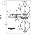
- FIG. 2 is an overview configuration diagram of a throttle unit (second throttle unit 12).
- FIG. 3 is an internal structure diagram of a deceleration mechanism 20 (decelerator).
- the throttle device 10 is a multi-throttle device attached to a multi-cylinder engine.
- the throttle device 10 according to this embodiment is employed in an inline four-cylinder engine 1 mounted on a vehicle such as a motorcycle.
- a vehicle such as a motorcycle.
- four cylinders (2a, 2b, 2c, and 2d) from #1 to #4 are disposed to be aligned in a vehicle width direction (left-right direction) in the vehicle.
- the throttle device 10 has a first throttle unit 11 (throttle unit) for a #1 cylinder 2a and a #2 cylinder 2b disposed on one side of the engine 1 in the vehicle width direction and a second throttle unit 12 (throttle unit) for a #3 cylinder 2c and a #4 cylinder 2d disposed on the other side of the engine 1 in the vehicle width direction.
- the first throttle unit 11 and the second throttle unit 12 are disposed to be aligned on the left and right sides in the vehicle width direction.
- the first throttle unit 11 and the second throttle unit 12 are configured to be symmetric on the left and right sides.
- the first throttle unit 11 includes a first segment body 14a in which an intake air passage 13a of the #1 cylinder 2a is formed and a second segment body 14b in which an intake air passage 13b of the #2 cylinder 2b is formed.
- the second throttle unit 12 includes a second segment body 14b in which an intake air passage 13c of the #3 cylinder 2c is formed and a first segment body 14a in which an intake air passage 13d of the #4 cylinder 2d is formed.
- each of the first throttle unit 11 and the second throttle unit 12 further includes a throttle shaft 15, throttle valves 16b to 16d, motors 17a and 17b (motors), a deceleration mechanism 20, a return spring 21, and a throttle position sensor 22.
- FIG. 2 illustrates the internal structure of the second throttle unit 12 and the intake air passage 13c is provided with the throttle valve 16c while the intake air passage 13d is provided with the throttle valve 16d.
- the intake air passage 13a is provided with the throttle valve 16a while the intake air passage 13b is provided with the throttle valve 16b.
- the first segment body 14a and the second segment body 14b are disposed to be aligned in the left-right direction (vehicle width direction) in accordance with the corresponding cylinders 2a to 2d to form a unit body 23 (throttle body).
- the intake air passages 13a to 13d are formed to extend perpendicularly (in the front-back direction in FIGS. 1 and 2 ) to the left-right direction.
- the throttle shaft 15 extends in the vehicle width direction through the unit body 23, passes through the inside of the two intake air passages (13a and 13c or 13c and 13d), and is rotatably supported by the unit body 23.
- the throttle valves 16a to 16d are disk-shaped members that have substantially the same diameter as the inner diameter of the intake air passages 13a to 13d, are secured to the throttle shaft 15, and are disposed inside the intake air passages 13a to 13d.
- the throttle valves 16a to 16d rotate inside the intake air passages 13a to 13d along with rotation of the throttle shaft 15 and can rotate at an arbitrary angle between a closed position at which the intake air passages 13a to 13d are closed and an opened position at which the intake air passages 13a to 13d are opened.
- the first motor 17a and the second motor 17b are electric motors.
- the first motor 17a and the second motor 17b are secured to second segment bodies 14b of the throttle units 11 and 12, respectively, and rotation drive shaft 24 thereof are disposed parallel to the throttle shafts 15.
- the deceleration mechanism 20 is disposed between the first segment body 14a and the second segment body 14b. As illustrated in FIG. 3 , the deceleration mechanism 20 has an intermediate axis 25, a first gear 26 secured to the rotation drive shaft 24 of the motors (the first motor 17a and the second motor 17b), a second gear 27 secured to the intermediate axis 25 and engaged with the first gear 26, a third gear 28 secured to the intermediate axis 25, and a fourth gear 29 secured to the throttle shaft 15 and engaged with the third gear 28.
- the intermediate axis 25 is disposed to be parallel to the rotation drive shaft 24 and the throttle shaft 15 and is rotatably supported by the unit body 23.
- the deceleration mechanism 20 transmits the rotation of the rotation drive shaft 24 of the motors (the first motor 17a and the second motor 17b) to the first gear 26, the second gear 27, the intermediate axis 25, the third gear 28, and the fourth gear 29 in this order to decelerate the rotation and drives and rotates the throttle shaft 15.
- the return spring 21 is a torsion spring disposed to be wound around the throttle shaft 15 several times and including one end portion supported by the unit body 23 and the other end portion supported by the throttle shaft 15. The return spring 21 biases the throttle shaft 15 to bring the throttle valves 16c and 16d into the closed state.
- the throttle position sensor 22 is provided at the one end portion of the throttle shaft 15 and functions to detect the rotational angle of the throttle shaft 15.
- the throttle position sensor 22 is disposed in the first segment body 14a, for example.
- the second segment bodies 14b of the first throttle unit 11 and the second throttle unit 12 are disposed inward in the left-right direction, that is, the first motor 17a (motor) of the first throttle unit 11 and the second motor 17b (motor) of the second throttle unit 12 are disposed inward in the left-right direction, and the throttle position sensor 22 is disposed outward in the left-right direction, in the throttle device 10.
- the first throttle unit 11 includes fuel injection valves 30a and 30b injecting a fuel into the intake air passages 13a and 13b.
- the second throttle unit 12 includes fuel injection valves 30c and 30d injecting a fuel into the intake air passages 13a and 13b.
- the throttle device 10 includes a total of four fuel injection valves 30a to 30d corresponding to the cylinders 2a to 2d.
- the fuel is supplied from a fuel pump, which is not illustrated, to the two fuel injection valves 30a and 30b included in the first throttle unit 11 via a fuel pipe 31. Also, the fuel is supplied from a fuel pump, which is not illustrated, to the two fuel injection valves 30c and 30d included in the second throttle unit 12 via a fuel pipe 32.
- FIG. 4 is an electric circuit diagram for driving the throttle device 10.
- Driving of each of the first motor 17a of the first throttle unit 11 and the second motor 17b of the second throttle unit 12 in the throttle device 10 is controlled by the control unit 40.
- the control unit 40 is a control device for controlling operations of the engine 1 and is configured to include an input/output device, a storage device (such as a ROM, a RAM, or a nonvolatile RAM), a central processing unit (CPU), and the like.
- the control unit 40 inputs a degree of opening of an accelerator detected by an accelerator opening degree sensor 41 provided in the vehicle, applies a predetermined voltage of the first motor 17a of the first throttle unit 11 and the second motor 17b of the second throttle unit 12, outputs a drive current, controls driving of each of the motors 17a and 17b, and controls operations of each of the fuel injection valves 30a to 30d.
- the rotational angle of the throttle shaft 15 detected by the throttle position sensor 22 is input for each of the first throttle unit 11 and the second throttle unit 12, and feedback control is performed such that the rotational angle of the throttle shaft 15 is obtained in accordance with the degree of accelerator opening.
- control unit 40 includes a cylinder deactivation control unit 42 executing a cylinder deactivated operation.
- the cylinder deactivation control unit 42 controls driving of the second motor 17b such that the throttle valves 16c and 16d in the second throttle unit 12 are brought into a fully opened state (predetermined degree of opening) and stops fuel injection through the fuel injection valves 30c and 30d, in a predetermined operation region of the engine 1, for example, in response to a low output request for a degree of accelerator opening of equal to or less than a predetermined value.
- operations of the first motor 17a and the fuel injection valves 30a and 30b in the first throttle unit 11 are controlled in accordance with a requested output based on an accelerator operation or the like even in the predetermined operation region.
- the second motor 17b for the #3 and #4 cylinders 2c and 2d that are subjected to cylinder deactivation to have a specification with a higher responsivity to a change in rotation speed than that of the first motor 17a for the #1 and #2 cylinders 2a and 2b that are not subjected to cylinder deactivation. It is only necessary to cause the second motor 17b to have a thicker wire diameter or a reduced number of windings of the coil than that of the first motor 17a, for example. It is possible to reduce a resistance of the coil by increasing the wire diameter or reducing the number of windings of the coil.
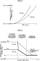
- FIG. 5 is a graph illustrating a transition example of a degree of throttle opening of the throttle valves 16a and 16b and throttle valves 16c and 16d from the fully closed state to the fully opened state.
- FIG. 5 illustrates transition of the degree of opening of each of the throttle valves (16a and 16b, and 16c and 16d) in a case in which the same voltage (predetermined voltage) is applied to the first motor 17a and the second motor 17b at the same time.
- FIG. 6 is a graph illustrating a transition example of a degree of throttle opening at the time of transition from the cylinder deactivated operation to the ordinary operation.
- FIG. 6 illustrates transition of the degrees of opening of the throttle valves 16a, 16b, 16c, and 16d until the degrees of opening of the throttle valves 16a, 16b, 16c, and 16d transition to a predetermined degree of opening Vo1 when the cylinder deactivated operation is released from the cylinder deactivated operation state and transition to the ordinary operation is achieved.
- FIG. 6 illustrates a case in which a requested output of the engine slightly increases from the cylinder deactivated operation state and transitions to the ordinary operation in which combustion is carried out in all the cylinders 2a to 2d is achieved.
- the degree of opening (predetermined degree of opening Vo2) of the throttle valves 16a and 16b in the cylinder deactivated operation state is greater than the degree of opening (predetermined degree of opening Vo1) of the throttle valves 16a, 16b, 16c, and 16d in the ordinary operation.
- the second motor 17b with a higher responsivity more quickly operates than the first motor 17a, and the degree of opening of the throttle valves 16c and 16d driven by the second motor 17b is brought into the fully opened state in an early stage.
- the degree of opening of the throttle valves 16a and 16b in the first throttle unit 11 is the degree of throttle opening Vo2 corresponding to the requested output based on an accelerator operation or the like while the degree of opening of the throttle valves 16b and 16d in the second throttle unit 12 is a fully opened state.
- each of the first motor 17a and the second motor 17b is controlled to achieve the ordinary operation in which all the throttle valves 16a to 16d have the requested degree of opening Vo1 based on the accelerator operation or the like.
- the degree of opening of the throttle valves 16c and 16d in the second throttle unit 12 and the degree of opening of the throttle valves 16a and 16b in the first throttle unit 11 transition at equivalent speeds, as represented by the dashed line in FIG. 6 .
- a period of time during which the degree of opening of the throttle valves 16c and 16d does not reach the predetermined degree of opening Vo1 occurs even when the degree of opening of the throttle valves 16a and 16b reaches the predetermined degree of opening Vo1.
- the degree of opening of the throttle valves 16c and 16d and the degree of opening of the throttle valves 16a and 16b conform to each other before the degree of opening of the throttle valves 16a and 16b in the first throttle unit 11 reaches a predetermined degree of opening Vo1 as represented by the thick solid line in FIG. 6 .
- each of the first motor 17a and the second motor 17b may be controlled such that the transition is carried out with the degree of opening of the throttle valves 16c and 16d and the degree of opening of the throttle valves 16a and 16b maintained to conform to each other, until the predetermined degree of opening Vo1 is reached after the degree of opening of the throttle valves 16c and 16d and the degree of opening of the throttle valves 16a and 16b conform to each other.
- the degree of opening of the throttle valves 16a and 16b in the first throttle unit 11 thus conforms to the degree of opening of the throttle valves 16c and 16d in the second throttle unit 12 in an early stage when the transition from the cylinder deactivated operation to the ordinary operation is achieved in this embodiment, it is possible to quickly cause the outputs of the #1 and #2 cylinders 2a and 2b to conform to the outputs of the #3 and #4 cylinders 2c and 2d, to smooth the output of the engine, and thereby to improve an output feeling.
- the throttle device 10 is the multi-throttle device 10 provided with the throttle valves 16a to 16d in the intake air passages 13a to 13d of the four cylinders 2a to 2d in the engine 1 and includes the two throttle units 11 and 12.
- the throttle device 10 has a structure in which the first motor 17a included in the first throttle unit 11 drives the two throttle valves 16a and 16b while the second motor 17b included in the second throttle unit 12 drives the two throttle valves 16a and 16b.
- the first motor 17a of the first throttle unit 11 and the second motor 17b of the second throttle unit 12 are caused to have mutually different responsivities to a change in rotation speed.
- the engine 1 include the cylinder deactivated operation function and changes the degree of opening of the throttle valve 16b in the second throttle unit 12 corresponding to a part of the four cylinders 2a to 2d, namely the cylinders 2c and 2d into a fully opened state at the time of a low requested output.
- the second motor 17b of the second throttle unit 12 that is caused to operate in a fully opened state in the cylinder deactivated operation function is caused to have a specification with a higher responsivity than the first motor 17a of the first throttle unit 11 in which the cylinders are not deactivated in the cylinder deactivated operation, it is possible to curb an uncomfortable feeling from an output of the engine 1 with a simple configuration by quickly reducing the degree of opening of the throttle valves 16c and 16d in the second throttle unit 12 to the same degree of opening of the throttle valves 16a and 16b in the first throttle unit 11 when the cylinder deactivated operation is released. Also, it is possible to use a motor that is less responsive than the second motor 17b as the first motor 17a and thereby to curb a component cost of the first motor 17a.
- the control unit 40 may perform drive current output control such that the drive currents of the first motor 17a and the second motor 17b are different from each other. For example, it is only necessary to set the drive current to be supplied to the second motor 17b that deactivates the cylinders in the cylinder deactivated operation function to be higher than the drive current to be supplied to the first motor 17a that is not used in the cylinder deactivation.
- the deceleration ratio of the deceleration mechanism 20 in the first throttle unit 11 and the deceleration ratio of the deceleration mechanism 20 in the second throttle unit 12 may further be set to different deceleration ratios.
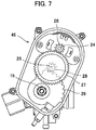
- FIG. 7 is a structure diagram of a deceleration mechanism 45 (decelerator) according to another embodiment in the second throttle unit 12.
- the gear ratio of the third gear 28 and the fourth gear 29 in the deceleration mechanism 45 in the second throttle unit 12 used for the cylinder deactivated operation function may be set lower than the gear ratio in the deceleration mechanism 20 in the first throttle unit 11, which is set to a gear ratio similar to that of the deceleration mechanism 20 illustrated in FIG. 3 , as illustrated in FIG. 7 in aforementioned embodiment.
- the gear ratio of the first gear 26 and the second gear 27 may be set to be low instead of or along with that of the third gear 28 and the fourth gear 29.
- the deceleration mechanisms 20 and 45 in the aforementioned embodiment may have structures in which set torques of the return springs 21 can be changed.
- the set torques of the return springs 21 are biasing torques toward the closed direction caused by the return springs 21 in the closed state of the throttle valves 16a to 16d.
- FIG. 8 is an assembly diagram of an attachment unit of the return spring 21 in the second throttle unit 12.
- FIG. 9 is an explanatory diagram illustrating an installation state of the return spring 21 in the first throttle unit 11.
- FIG. 10 is an explanatory diagram illustrating an installation state of the return spring 21 in the second throttle unit 12. Note that the up-down direction in FIG. 8 is opposite of that in FIGS. 1 to 3 , 7 , 9 , and 10 for easiness of viewing the attachment unit of the return spring 21, and the throttle shaft 15 is illustrated above the motor 17.
- the first throttle unit 11 and the second throttle unit 12 are bilaterally symmetric, the first throttle unit 11 and the second throttle unit 12 are illustrated in a left-side-right manner in FIG. 9 for easiness of comparison between the first throttle unit 11 and the second throttle unit 12.
- a cylindrical rib 52 projecting outward in an axial line direction of an insertion hole 51 is formed around the insertion hole 51, into which the throttle shaft 15 is inserted, at an end portion (specifically, the end portion of the second segment body 14b on the side of the deceleration mechanism 20) of the unit body 23.
- two projections are formed outside the rib 52 in the radial direction at the end portion of the second segment body 14b.
- the first projection 53a and the second projection 53b have columnar shapes with a diameter of about several mm, for example, project outward in the axial line direction of the insertion hole 51 in parallel with the rib 52, and project up to the vicinity of the distal end of the rib 52.
- the first projection 53a and the second projection 53b are disposed at mutually opposite positions with the insertion hole 51 sandwiched therebetween, for example, at an interval from each other in a circumferential direction on a concentric circle around the insertion hole 51 at the center.
- Both end portions 21a and 21b of the return spring 21 project outward in the radial direction.
- the return spring 21 is disposed such that the distal end portion of the rib 52 is inserted thereinto, and is configured such that the end portion 21a on the side of the second segment body 14b can be locked at the first projection 53a and the second projection 53b.
- a fourth gear 29 and the throttle shaft 15 are secured to each other via a disk-shaped hook plate 55.
- a shaft coupling hole 55a into which the throttle shaft 15 is inserted is provided at the center of the hook plate 55.
- the shaft coupling hole 55a and the distal end portion of the throttle shaft 15 are formed into rectangular shapes, for example, and the throttle shaft 15 and the hook plate 55 are coupled such that the throttle shaft 15 and the hook plate 55 cannot rotate relative to each other, that is, rotation of the fourth gear 29 is transmitted to the throttle shaft 15.
- a step difference 15a positioning the hook plate 55 in the axial direction is provided at the distal end portion of the throttle shaft 15.
- the return spring 21 is disposed between the hook plate 55 disposed with the distal end portion of the throttle shaft 15 inserted thereinto and the second segment body 14b.
- the fourth gear 29 is secured to the outside of the hook plate 55 with a plurality of bolts, for example.
- a first hook 55b and a second hook 55d extend outward in the radial direction with distal ends bent toward the axial direction (on the side of the second segment body 14b) and a stopper 55c are formed at the end portion the outer peripheral portion of the hook plate 55.
- the first hook 55b and the second hook 55d are disposed at an interval from each other in a circumferential direction on a concentric circle around the shaft coupling hole 55a at the center. Grooves, for example, are formed in both the first hook 55b and the second hook 55d such that the end portion 21b of the return spring 21 is easily locked at the grooves.
- the stopper 55c abuts on a stopper bolt 56 provided in the second segment body 14b and prevents rotation of the throttle shaft 15 in one direction (right rotation in FIG. 8 ).
- the stopper bolt 56 is adapted such that an abutting position with respect to the stopper 55c can be adjusted.
- the return spring 21 biases the hook plate 55 in one rotation direction (right rotation in FIG. 8 ) relative to the second segment body 14b, the rotation is prevented at a predetermined rotation position by the stopper 55c.
- the throttle shaft 15 is biased to rotate relative to the unit body 23 by a biasing force of the return spring 21. In this manner, the throttle valves 16c and 16d (16a and 16b in the first throttle unit 11) are closed when the motor 17 does not operate.
- the fourth gear 29 rotates against the biasing of the return spring 21 (left rotation in FIG. 8 ) via the deceleration mechanism 20 by operating the motor 17.
- the projections 53a and 53b are provided at two locations of the second segment body 14b, and the end portion 21a of the return spring 21 on the side of the second segment body 14b can be selectively locked at any one of the projections 53a and 53b.
- the throttle valves 16c and 16d (16a and 16b) are biased in the closed direction by the biasing of the return spring 21, and the throttle valves 16c and 16d (16a and 16b) are brought into a closed state when the motor 17 does not operate.
- the biasing torque of the return spring 21 in the closed state namely, the set torque of maintaining the throttle valves 16c and 16d (16a and 16b) in the closed state are defined by the locking position of the end portion 21a of the return spring 21.
- the set torque is set to be relatively small by locking the end portion 21a of the return spring 21 at the first projection 53a in the first throttle unit 11.
- the set torque is set to be relatively large by locking the end portion 21a of the return spring 21 at the second projection 53b in the second throttle unit 12.
- first hook 55b and the second hook 55d are formed in the hook plate 55, and the set torque can be changed depending on which of the first hook 55b and the second hook 55d the end portion 21b of the return spring 21 is to be locked at.
- the set torque is set to be relatively small by locking the end portion 21b of the return spring 21 at the first hook 55b in the first throttle unit 11.
- the set torque is set to be relatively large by locking the end portion 21b of the return spring 21 at the second hook 55d in the second throttle unit 12.
- the aspects of the present invention are not limited to the aforementioned embodiments.
- the present invention is applied to the engine 1 provided with the cylinder deactivated operation function in the aforementioned embodiments, the present invention may be applied to an engine with no cylinder deactivated operation function.
- the present invention is applied to the throttle device 10 in the four-cylinder engine 1 in the embodiments, the present invention may be applied to a throttle device for an engine with a plurality of cylinders instead of the four-cylinder engine.
- the throttle device 10 has the two throttle units 11 and 12, and the total of two motors 17a and 17b for each two of the four cylinders drive the throttle valves for the cylinders
- the throttle device may include three or more throttle units and motors.
- the number of throttle valves operated by each motor may be any number instead of two.
- the throttle device according to the present invention can be employed for an engine used for applications other than the motorcycle.
- the present invention is employed in a multi-cylinder engine and can widely be applied to a throttle device in which a plurality of motors share operations of opening and closing a plurality of throttle valves.
Landscapes
- Engineering & Computer Science (AREA)
- Chemical & Material Sciences (AREA)
- Combustion & Propulsion (AREA)
- Mechanical Engineering (AREA)
- General Engineering & Computer Science (AREA)
- Control Of Throttle Valves Provided In The Intake System Or In The Exhaust System (AREA)
Abstract
Description
- The present invention relates to a throttle device controlling intake air of an engine.
- Many of engines mounted on vehicles such as motorcycles for driving the vehicles to travel have a plurality of cylinders to obtain high outputs. Further, multi-throttle devices that provide throttle valves for each of the plurality of cylinders have widely been employed in motorcycles to improve engine outputs.
- For example, Japanese Patent Laid-Open No.
2005-282463 - According to such an engine provided with throttle valves for each of cylinders and provided with a plurality of motors for driving the throttle valves as described above, cases in which degrees of opening of the throttle valves significantly differ from each other may occur due to the individual control of the driving of the motors. According to such an engine provided with the cylinder deactivated operation function as in the aforementioned document, throttle valves of the part of cylinders that are deactivated are set to have predetermined degrees of opening (in a closed state, for example) at the time of the cylinder deactivated operation, and the degree of opening of the throttle valves of the cylinders that are deactivated and of the cylinders that are not deactivated at the time of the cylinder deactivated operation may thus significantly differ from each other, for example.
- There is a possibility that when it is attempted to control all the throttle valves to have the same target degree of opening, for example, from such a state in which the degrees of opening of the throttle valves significantly differ from each other in this manner, the difference in degree of opening of the throttle valves is not immediately solved at the time of shifting to the target degree of opening and a driver of the vehicle have an uncomfortable feeling due to a difference in outputs of the cylinders caused by the difference in degree of opening of the throttle valves.
- An object of the present invention, which has made in view of such circumstances, is to provide a multi-throttle valve device that is employed in multi-cylinder engine and is capable of curbing an uncomfortable feeling due to a difference in outputs of the cylinders.
- In order to achieve the aforementioned object, a throttle device according to the present invention includes: a plurality of throttle units provided in an engine for each of cylinders or for each of cylinder groups, each of the throttle units including a throttle body having intake air passages corresponding to the plurality of cylinders of the engine, a throttle shaft rotatably supported by the throttle body, throttle valves secured to the throttle shaft to open and close the intake air passages for the cylinders, and a motor driving and rotating the throttle shaft, in which a first motor that is the motor provided in a first throttle unit and a second motor that is the motor provided in a second throttle unit out of the plurality of throttle units have mutually different responsivities to a change in rotation speed.
- Preferably, the first motor and the second motor are electric motors, and at least either numbers of windings or wire diameters of the coils of the first motor and the second motor are set to be mutually different.
- Preferably, the throttle device further includes: a control unit outputting driving currents of the first motor and the second motor, and the control unit outputs the driving currents different from each other to the first motor and the second motor to set mutually different responsivities to a change in rotation speed for the first motor and the second motor.
- Preferably, the throttle device further includes: a cylinder deactivation control unit stopping only operations of the second motor out of the first motor and the second motor and causing the throttle valves of the second throttle unit to have a predetermined degree of opening in a predetermined operating region of the engine, and deactivating combustion of the cylinders or the cylinder groups corresponding to the second throttle unit, and the responsivity to a change in rotation speed of the second motor is higher than the responsivity to a change in rotation speed of the first motor.
- Preferably, each of the first throttle unit and the second throttle unit includes a decelerator decelerating rotation of a drive shaft of the motor and transmitting the decelerated rotation to the throttle shaft, and a deceleration ratio of the decelerator in the first throttle unit and a deceleration ratio of the decelerator in the second throttle unit are different from each other.
- Preferably, two units being the throttle units are provided in the engine.
- Preferably, the throttle device is provided in the engine of a motorcycle.
- According to the throttle device of the present invention, it is possible to set the opening/closing speeds of the throttle valve of the first throttle unit and of the throttle valve of the second throttle unit to be different from each other and thereby to immediately solve a difference in degree of opening of the throttle valves in a case in which the first motor and the second motor are driven to have the same predetermined degree of opening from a state in which the degrees of opening of the throttle valves are different from each other. It is thus possible to quickly solve a difference between an output of the cylinder, intake air of which is controlled by the first throttle unit, and an output of the cylinder, intake air of which is controlled by the second throttle unit, to obtain a smooth engine output, and to curb an uncomfortable feeling of a driver.
-
-
FIG. 1 is an external view of a throttle device according to an embodiment of the present invention; -
FIG. 2 is an overview configuration diagram of a throttle unit; -
FIG. 3 is an internal structure diagram of a deceleration mechanism; -
FIG. 4 is an electric circuit diagram for driving the throttle device; -
FIG. 5 is a graph illustrating a transition example of a degree of throttle opening from a fully closed state to a fully opened state of throttle valves; -
FIG. 6 is a graph illustrating a transition example of the degree of throttle opening at the time of shifting from a cylinder deactivated operation to an ordinary operation; -
FIG. 7 is a structure diagram of a deceleration mechanism according to another embodiment of a second throttle unit; -
FIG. 8 is an assembly diagram of an attachment unit of a return spring in the second throttle unit; -
FIG. 9 is an explanatory diagram illustrating an installation state of the return spring in a first throttle unit; and -
FIG. 10 is an explanatory diagram illustrating an installation state of the return spring in a second throttle unit. - Hereinafter, an embodiment of the present invention will be described on the basis of drawings.
-
FIG. 1 is an external view of athrottle device 10 according to an embodiment of the present invention.FIG. 2 is an overview configuration diagram of a throttle unit (second throttle unit 12).FIG. 3 is an internal structure diagram of a deceleration mechanism 20 (decelerator). - The
throttle device 10 according to the present invention is a multi-throttle device attached to a multi-cylinder engine. Thethrottle device 10 according to this embodiment is employed in an inline four-cylinder engine 1 mounted on a vehicle such as a motorcycle. For the engine 1, four cylinders (2a, 2b, 2c, and 2d) from #1 to #4 are disposed to be aligned in a vehicle width direction (left-right direction) in the vehicle. - As illustrated in
FIG. 1 , thethrottle device 10 has a first throttle unit 11 (throttle unit) for a #1cylinder 2a and a #2cylinder 2b disposed on one side of the engine 1 in the vehicle width direction and a second throttle unit 12 (throttle unit) for a #3cylinder 2c and a #4cylinder 2d disposed on the other side of the engine 1 in the vehicle width direction. Thefirst throttle unit 11 and thesecond throttle unit 12 are disposed to be aligned on the left and right sides in the vehicle width direction. - The
first throttle unit 11 and thesecond throttle unit 12 are configured to be symmetric on the left and right sides. - The
first throttle unit 11 includes afirst segment body 14a in which anintake air passage 13a of the #1cylinder 2a is formed and asecond segment body 14b in which anintake air passage 13b of the #2cylinder 2b is formed. - The
second throttle unit 12 includes asecond segment body 14b in which anintake air passage 13c of the #3cylinder 2c is formed and afirst segment body 14a in which anintake air passage 13d of the #4cylinder 2d is formed. - As illustrated in
FIGS. 1 and2 , each of thefirst throttle unit 11 and thesecond throttle unit 12 further includes athrottle shaft 15,throttle valves 16b to 16d,motors deceleration mechanism 20, areturn spring 21, and athrottle position sensor 22. Note thatFIG. 2 illustrates the internal structure of thesecond throttle unit 12 and theintake air passage 13c is provided with thethrottle valve 16c while theintake air passage 13d is provided with thethrottle valve 16d. In thefirst throttle unit 11, theintake air passage 13a is provided with thethrottle valve 16a while theintake air passage 13b is provided with thethrottle valve 16b. - The
first segment body 14a and thesecond segment body 14b are disposed to be aligned in the left-right direction (vehicle width direction) in accordance with thecorresponding cylinders 2a to 2d to form a unit body 23 (throttle body). - The
intake air passages 13a to 13d are formed to extend perpendicularly (in the front-back direction inFIGS. 1 and2 ) to the left-right direction. Thethrottle shaft 15 extends in the vehicle width direction through theunit body 23, passes through the inside of the two intake air passages (13a and 13c or 13c and 13d), and is rotatably supported by theunit body 23. - The
throttle valves 16a to 16d are disk-shaped members that have substantially the same diameter as the inner diameter of theintake air passages 13a to 13d, are secured to thethrottle shaft 15, and are disposed inside theintake air passages 13a to 13d. Thethrottle valves 16a to 16d rotate inside theintake air passages 13a to 13d along with rotation of thethrottle shaft 15 and can rotate at an arbitrary angle between a closed position at which theintake air passages 13a to 13d are closed and an opened position at which theintake air passages 13a to 13d are opened. - The
first motor 17a and thesecond motor 17b are electric motors. Thefirst motor 17a and thesecond motor 17b are secured tosecond segment bodies 14b of thethrottle units rotation drive shaft 24 thereof are disposed parallel to thethrottle shafts 15. - The
deceleration mechanism 20 is disposed between thefirst segment body 14a and thesecond segment body 14b. As illustrated inFIG. 3 , thedeceleration mechanism 20 has anintermediate axis 25, afirst gear 26 secured to therotation drive shaft 24 of the motors (thefirst motor 17a and thesecond motor 17b), asecond gear 27 secured to theintermediate axis 25 and engaged with thefirst gear 26, athird gear 28 secured to theintermediate axis 25, and afourth gear 29 secured to thethrottle shaft 15 and engaged with thethird gear 28. Theintermediate axis 25 is disposed to be parallel to therotation drive shaft 24 and thethrottle shaft 15 and is rotatably supported by theunit body 23. - The
deceleration mechanism 20 transmits the rotation of therotation drive shaft 24 of the motors (thefirst motor 17a and thesecond motor 17b) to thefirst gear 26, thesecond gear 27, theintermediate axis 25, thethird gear 28, and thefourth gear 29 in this order to decelerate the rotation and drives and rotates thethrottle shaft 15. - The
return spring 21 is a torsion spring disposed to be wound around thethrottle shaft 15 several times and including one end portion supported by theunit body 23 and the other end portion supported by thethrottle shaft 15. Thereturn spring 21 biases thethrottle shaft 15 to bring thethrottle valves - The
throttle position sensor 22 is provided at the one end portion of thethrottle shaft 15 and functions to detect the rotational angle of thethrottle shaft 15. Thethrottle position sensor 22 is disposed in thefirst segment body 14a, for example. - As illustrated in
FIG. 1 , thesecond segment bodies 14b of thefirst throttle unit 11 and thesecond throttle unit 12 are disposed inward in the left-right direction, that is, thefirst motor 17a (motor) of thefirst throttle unit 11 and thesecond motor 17b (motor) of thesecond throttle unit 12 are disposed inward in the left-right direction, and thethrottle position sensor 22 is disposed outward in the left-right direction, in thethrottle device 10. - Also, the
first throttle unit 11 includesfuel injection valves intake air passages second throttle unit 12 includesfuel injection valves intake air passages throttle device 10 includes a total of fourfuel injection valves 30a to 30d corresponding to thecylinders 2a to 2d. - The fuel is supplied from a fuel pump, which is not illustrated, to the two
fuel injection valves first throttle unit 11 via afuel pipe 31. Also, the fuel is supplied from a fuel pump, which is not illustrated, to the twofuel injection valves second throttle unit 12 via afuel pipe 32. -
FIG. 4 is an electric circuit diagram for driving thethrottle device 10. - Driving of each of the
first motor 17a of thefirst throttle unit 11 and thesecond motor 17b of thesecond throttle unit 12 in thethrottle device 10 is controlled by thecontrol unit 40. - The
control unit 40 is a control device for controlling operations of the engine 1 and is configured to include an input/output device, a storage device (such as a ROM, a RAM, or a nonvolatile RAM), a central processing unit (CPU), and the like. Thecontrol unit 40 inputs a degree of opening of an accelerator detected by an acceleratoropening degree sensor 41 provided in the vehicle, applies a predetermined voltage of thefirst motor 17a of thefirst throttle unit 11 and thesecond motor 17b of thesecond throttle unit 12, outputs a drive current, controls driving of each of themotors fuel injection valves 30a to 30d. At this time, the rotational angle of thethrottle shaft 15 detected by thethrottle position sensor 22 is input for each of thefirst throttle unit 11 and thesecond throttle unit 12, and feedback control is performed such that the rotational angle of thethrottle shaft 15 is obtained in accordance with the degree of accelerator opening. - In addition, the
control unit 40 includes a cylinderdeactivation control unit 42 executing a cylinder deactivated operation. - The cylinder
deactivation control unit 42 controls driving of thesecond motor 17b such that thethrottle valves second throttle unit 12 are brought into a fully opened state (predetermined degree of opening) and stops fuel injection through thefuel injection valves first motor 17a and thefuel injection valves first throttle unit 11 are controlled in accordance with a requested output based on an accelerator operation or the like even in the predetermined operation region. - In this manner, the combustion in the two #3 and #4
cylinders cylinders 2a to 2d in the engine 1 is stopped. Thus, since fuel consumption at the #3 and #4cylinders throttle valves cylinders - Further, in this embodiment, the
second motor 17b for the #3 and #4cylinders first motor 17a for the #1 and #2cylinders second motor 17b to have a thicker wire diameter or a reduced number of windings of the coil than that of thefirst motor 17a, for example. It is possible to reduce a resistance of the coil by increasing the wire diameter or reducing the number of windings of the coil. It is thus possible to increase a current flowing through thesecond motor 17b with a low coil resistance and to improve the responsivity of thesecond motor 17b as compared with thefirst motor 17a when the same voltage is applied to thefirst motor 17a and thesecond motor 17b. -
FIG. 5 is a graph illustrating a transition example of a degree of throttle opening of thethrottle valves throttle valves FIG. 5 illustrates transition of the degree of opening of each of the throttle valves (16a and 16b, and 16c and 16d) in a case in which the same voltage (predetermined voltage) is applied to thefirst motor 17a and thesecond motor 17b at the same time. -
FIG. 6 is a graph illustrating a transition example of a degree of throttle opening at the time of transition from the cylinder deactivated operation to the ordinary operation.FIG. 6 illustrates transition of the degrees of opening of thethrottle valves throttle valves FIG. 6 illustrates a case in which a requested output of the engine slightly increases from the cylinder deactivated operation state and transitions to the ordinary operation in which combustion is carried out in all thecylinders 2a to 2d is achieved. Note that in order to avoid large variation in the output of the entire engine 1, when the requested output of the engine 1 slightly increases from the cylinder deactivated operation state and switching to the ordinary operation is achieved, the degree of opening (predetermined degree of opening Vo2) of thethrottle valves throttle valves - As illustrated in
FIG. 5 , in a case in which the same voltage is applied to thefirst motor 17a and thesecond motor 17b at the same time from the fully closed state, thesecond motor 17b with a higher responsivity more quickly operates than thefirst motor 17a, and the degree of opening of thethrottle valves second motor 17b is brought into the fully opened state in an early stage. - As illustrated in
FIG. 6 , the degree of opening of thethrottle valves first throttle unit 11 is the degree of throttle opening Vo2 corresponding to the requested output based on an accelerator operation or the like while the degree of opening of thethrottle valves second throttle unit 12 is a fully opened state. Also, in a case in which an operation of opening the accelerator is performed, a requested output increases, and the cylinder deactivated operation is released, for example, each of thefirst motor 17a and thesecond motor 17b is controlled to achieve the ordinary operation in which all thethrottle valves 16a to 16d have the requested degree of opening Vo1 based on the accelerator operation or the like. - Here, in a case in which the responsivity to a change in rotation speed of the
second motor 17b is equivalent to that of thefirst motor 17a in a comparative example, the degree of opening of thethrottle valves second throttle unit 12 and the degree of opening of thethrottle valves FIG. 6 ) transition at equivalent speeds, as represented by the dashed line inFIG. 6 . Thus, a period of time during which the degree of opening of thethrottle valves throttle valves throttle valves throttle valves cylinders cylinders - On the contrary, since the responsivity of the
second motor 17b is higher than that of thefirst motor 17a in this embodiment, the degree of opening of thethrottle valves throttle valves throttle valves first throttle unit 11 reaches a predetermined degree of opening Vo1 as represented by the thick solid line inFIG. 6 . Note that each of thefirst motor 17a and thesecond motor 17b may be controlled such that the transition is carried out with the degree of opening of thethrottle valves throttle valves throttle valves throttle valves - Since the degree of opening of the
throttle valves first throttle unit 11 thus conforms to the degree of opening of thethrottle valves second throttle unit 12 in an early stage when the transition from the cylinder deactivated operation to the ordinary operation is achieved in this embodiment, it is possible to quickly cause the outputs of the #1 and #2cylinders cylinders - As described above, the
throttle device 10 according to this embodiment is themulti-throttle device 10 provided with thethrottle valves 16a to 16d in theintake air passages 13a to 13d of the fourcylinders 2a to 2d in the engine 1 and includes the twothrottle units throttle device 10 has a structure in which thefirst motor 17a included in thefirst throttle unit 11 drives the twothrottle valves second motor 17b included in thesecond throttle unit 12 drives the twothrottle valves - Also, in this embodiment, the
first motor 17a of thefirst throttle unit 11 and thesecond motor 17b of thesecond throttle unit 12 are caused to have mutually different responsivities to a change in rotation speed. - In this manner, it is possible to cause the
throttle valves first throttle unit 11 and thethrottle valves second throttle unit 12 to be differently responsive to valve opening degree control with a simple configuration by causing thefirst motor 17a and thesecond motor 17b to have different responsivities. - Further, the engine 1 according to this embodiment include the cylinder deactivated operation function and changes the degree of opening of the
throttle valve 16b in thesecond throttle unit 12 corresponding to a part of the fourcylinders 2a to 2d, namely thecylinders - In this embodiment, since the
second motor 17b of thesecond throttle unit 12 that is caused to operate in a fully opened state in the cylinder deactivated operation function is caused to have a specification with a higher responsivity than thefirst motor 17a of thefirst throttle unit 11 in which the cylinders are not deactivated in the cylinder deactivated operation, it is possible to curb an uncomfortable feeling from an output of the engine 1 with a simple configuration by quickly reducing the degree of opening of thethrottle valves second throttle unit 12 to the same degree of opening of thethrottle valves first throttle unit 11 when the cylinder deactivated operation is released. Also, it is possible to use a motor that is less responsive than thesecond motor 17b as thefirst motor 17a and thereby to curb a component cost of thefirst motor 17a. - Note that although the
first motor 17a and thesecond motor 17b have different wiring diameters or numbers of windings of the coils in the aforementioned embodiment, thecontrol unit 40 may perform drive current output control such that the drive currents of thefirst motor 17a and thesecond motor 17b are different from each other. For example, it is only necessary to set the drive current to be supplied to thesecond motor 17b that deactivates the cylinders in the cylinder deactivated operation function to be higher than the drive current to be supplied to thefirst motor 17a that is not used in the cylinder deactivation. In this manner, it is possible to cause thefirst motor 17a and thesecond motor 17b even with the same specification to have different responsivities and to quickly cause the degrees of opening of thethrottle valves 16a to 16d to conform to each other when the cylinder deactivated operation state is released. - The deceleration ratio of the
deceleration mechanism 20 in thefirst throttle unit 11 and the deceleration ratio of thedeceleration mechanism 20 in thesecond throttle unit 12 may further be set to different deceleration ratios. -
FIG. 7 is a structure diagram of a deceleration mechanism 45 (decelerator) according to another embodiment in thesecond throttle unit 12. - For example, the gear ratio of the
third gear 28 and thefourth gear 29 in thedeceleration mechanism 45 in thesecond throttle unit 12 used for the cylinder deactivated operation function may be set lower than the gear ratio in thedeceleration mechanism 20 in thefirst throttle unit 11, which is set to a gear ratio similar to that of thedeceleration mechanism 20 illustrated inFIG. 3 , as illustrated inFIG. 7 in aforementioned embodiment. Note that the gear ratio of thefirst gear 26 and thesecond gear 27 may be set to be low instead of or along with that of thethird gear 28 and thefourth gear 29. - In this manner, it is possible to set the rotation speed of the
throttle shaft 15 in thesecond throttle unit 12 to be higher than the rotation speed of thethrottle shaft 15 in thefirst throttle unit 11. - In this manner, it is possible to change the opening/closing speeds of the
throttle valves 16a to 16d by causing thedeceleration mechanisms first throttle unit 11 and thesecond throttle unit 12 and thereby to further significantly change the responsivities. Thus, it is possible to significantly change the responsivities in thefirst throttle unit 11 and thesecond throttle unit 12 even in a case in which the wiring diameters or the numbers of windings of the coils are limited or a case in which operating currents to the coils are limited due to a limitation of the size of thefirst motor 17a or thesecond motor 17b, for example. - Also, the
deceleration mechanisms throttle valves 16a to 16d. -
FIG. 8 is an assembly diagram of an attachment unit of thereturn spring 21 in thesecond throttle unit 12.FIG. 9 is an explanatory diagram illustrating an installation state of thereturn spring 21 in thefirst throttle unit 11.FIG. 10 is an explanatory diagram illustrating an installation state of thereturn spring 21 in thesecond throttle unit 12. Note that the up-down direction inFIG. 8 is opposite of that inFIGS. 1 to 3 ,7 ,9 , and10 for easiness of viewing the attachment unit of thereturn spring 21, and thethrottle shaft 15 is illustrated above themotor 17. Although thefirst throttle unit 11 and thesecond throttle unit 12 are bilaterally symmetric, thefirst throttle unit 11 and thesecond throttle unit 12 are illustrated in a left-side-right manner inFIG. 9 for easiness of comparison between thefirst throttle unit 11 and thesecond throttle unit 12. - As illustrated in
FIG. 8 , acylindrical rib 52 projecting outward in an axial line direction of aninsertion hole 51 is formed around theinsertion hole 51, into which thethrottle shaft 15 is inserted, at an end portion (specifically, the end portion of thesecond segment body 14b on the side of the deceleration mechanism 20) of theunit body 23. Also, two projections (afirst projection 53a and asecond projection 53b) are formed outside therib 52 in the radial direction at the end portion of thesecond segment body 14b. Thefirst projection 53a and thesecond projection 53b have columnar shapes with a diameter of about several mm, for example, project outward in the axial line direction of theinsertion hole 51 in parallel with therib 52, and project up to the vicinity of the distal end of therib 52. Thefirst projection 53a and thesecond projection 53b are disposed at mutually opposite positions with theinsertion hole 51 sandwiched therebetween, for example, at an interval from each other in a circumferential direction on a concentric circle around theinsertion hole 51 at the center. - Both
end portions return spring 21 project outward in the radial direction. Thereturn spring 21 is disposed such that the distal end portion of therib 52 is inserted thereinto, and is configured such that theend portion 21a on the side of thesecond segment body 14b can be locked at thefirst projection 53a and thesecond projection 53b. - A
fourth gear 29 and thethrottle shaft 15 are secured to each other via a disk-shapedhook plate 55. Ashaft coupling hole 55a into which thethrottle shaft 15 is inserted is provided at the center of thehook plate 55. Theshaft coupling hole 55a and the distal end portion of thethrottle shaft 15 are formed into rectangular shapes, for example, and thethrottle shaft 15 and thehook plate 55 are coupled such that thethrottle shaft 15 and thehook plate 55 cannot rotate relative to each other, that is, rotation of thefourth gear 29 is transmitted to thethrottle shaft 15. - A
step difference 15a positioning thehook plate 55 in the axial direction is provided at the distal end portion of thethrottle shaft 15. Thereturn spring 21 is disposed between thehook plate 55 disposed with the distal end portion of thethrottle shaft 15 inserted thereinto and thesecond segment body 14b. Thefourth gear 29 is secured to the outside of thehook plate 55 with a plurality of bolts, for example. - A
first hook 55b and asecond hook 55d extend outward in the radial direction with distal ends bent toward the axial direction (on the side of thesecond segment body 14b) and astopper 55c are formed at the end portion the outer peripheral portion of thehook plate 55. Thefirst hook 55b and thesecond hook 55d are disposed at an interval from each other in a circumferential direction on a concentric circle around theshaft coupling hole 55a at the center. Grooves, for example, are formed in both thefirst hook 55b and thesecond hook 55d such that theend portion 21b of thereturn spring 21 is easily locked at the grooves. - The
stopper 55c abuts on astopper bolt 56 provided in thesecond segment body 14b and prevents rotation of thethrottle shaft 15 in one direction (right rotation inFIG. 8 ). Thestopper bolt 56 is adapted such that an abutting position with respect to thestopper 55c can be adjusted. - Although the
return spring 21 biases thehook plate 55 in one rotation direction (right rotation inFIG. 8 ) relative to thesecond segment body 14b, the rotation is prevented at a predetermined rotation position by thestopper 55c. In other words, thethrottle shaft 15 is biased to rotate relative to theunit body 23 by a biasing force of thereturn spring 21. In this manner, thethrottle valves motor 17 does not operate. - Also, the
fourth gear 29 rotates against the biasing of the return spring 21 (left rotation inFIG. 8 ) via thedeceleration mechanism 20 by operating themotor 17. - In the
deceleration mechanism 20 in this embodiment, theprojections second segment body 14b, and theend portion 21a of thereturn spring 21 on the side of thesecond segment body 14b can be selectively locked at any one of theprojections throttle valves return spring 21, and thethrottle valves motor 17 does not operate. The biasing torque of thereturn spring 21 in the closed state, namely, the set torque of maintaining thethrottle valves end portion 21a of thereturn spring 21. - As illustrated in
FIG. 9 , the set torque is set to be relatively small by locking theend portion 21a of thereturn spring 21 at thefirst projection 53a in thefirst throttle unit 11. - As illustrated in
FIG. 10 , the set torque is set to be relatively large by locking theend portion 21a of thereturn spring 21 at thesecond projection 53b in thesecond throttle unit 12. - Also, the
first hook 55b and thesecond hook 55d are formed in thehook plate 55, and the set torque can be changed depending on which of thefirst hook 55b and thesecond hook 55d theend portion 21b of thereturn spring 21 is to be locked at. - The set torque is set to be relatively small by locking the
end portion 21b of thereturn spring 21 at thefirst hook 55b in thefirst throttle unit 11. - The set torque is set to be relatively large by locking the
end portion 21b of thereturn spring 21 at thesecond hook 55d in thesecond throttle unit 12. - It is thus possible to cause the
throttle valves second throttle unit 12 that is subjected to cylinder deactivation to further quickly perform a closing operation as compared with thethrottle valves first throttle unit 11 that is not subjected to cylinder deactivation, when thethrottle valves 16a to 16d of thefirst throttle unit 11 and thesecond throttle unit 12 are caused to operate from the fully opened state to the fully closed state. - Although the description of the embodiments will now end, the aspects of the present invention are not limited to the aforementioned embodiments. For example, although the present invention is applied to the engine 1 provided with the cylinder deactivated operation function in the aforementioned embodiments, the present invention may be applied to an engine with no cylinder deactivated operation function.
- It is possible to immediately solve differences in degrees of opening of a plurality of throttle valves in a case in which control is performed to obtain the same degree of opening from the state in which the degrees of opening differ from each other, in an engine in which a state where the degrees of opening of the plurality of throttle valves differ from each other may occur regardless of the engine being not provided with the cylinder deactivated operation function. It is thus possible to achieve smooth operations of the engine with a simple configuration.
- Although the present invention is applied to the
throttle device 10 in the four-cylinder engine 1 in the embodiments, the present invention may be applied to a throttle device for an engine with a plurality of cylinders instead of the four-cylinder engine. - Although the
throttle device 10 according to the embodiment has the twothrottle units motors - The throttle device according to the present invention can be employed for an engine used for applications other than the motorcycle.
- The present invention is employed in a multi-cylinder engine and can widely be applied to a throttle device in which a plurality of motors share operations of opening and closing a plurality of throttle valves.
Claims (7)
- A throttle device (10) comprising:a plurality of throttle units (11, 12) provided in an engine (1) for each of cylinders or for each of cylinder groups, each of the throttle units includinga throttle body (23) having intake air passages (13a, 13b, 13c, 13d) corresponding to the plurality of cylinders (2a, 2b, 2c, 2d) of the engine (1),a throttle shaft (15) rotatably supported by the throttle body (23),throttle valves (16a, 16b, 16c, 16d) secured to the throttle shaft (15) to open and close the intake air passages (13a, 13b, 13c, 13d) for the cylinders (2a, 2b, 2c, 2d), anda motor (17a, 17b) driving and rotating the throttle shaft (15),wherein a first motor (17a) that is the motor provided in a first throttle unit (11) and a second motor (17b) that is the motor provided in a second throttle unit (12) out of the plurality of throttle units (11, 12) have mutually different responsivities to a change in rotation speed.
- The throttle device according to claim 1,
wherein the first motor (17a) and the second motor (17b) are electric motors, and
at least either numbers of windings or wire diameters of coils are set to be different between the first motor (17a) and the second motor (17b). - The throttle device according to claim 1 or 2, further comprising:a control unit (40) outputting drive currents to the first motor (17a) and the second motor (17b),wherein the control unit (40) outputs the drive currents different from each other to the first motor (17a) and the second motor (17b) to set mutually different responsivities to a change in rotation speed for the first motor (17a) and the second motor (17b).
- The throttle device according to any one of claims 1 to 3, comprising:a cylinder deactivation control unit (42) stopping operations only of the second motor (17b) out of the first motor (17a) and the second motor (17b) and setting the throttle valves (16c, 16d) of the second throttle unit (12) to have a predetermined degree of opening in a predetermined operating region of the engine (1), and deactivating combustion of the cylinder or the cylinder group (2c, 2d) corresponding to the second throttle unit (12),wherein the responsivity to a change in rotation speed of the second motor (17b) is higher than the responsivity to a change in rotation speed of the first motor (17a).
- The throttle device according to any one of claims 1 to 4,
wherein each of the first throttle unit (11) and the second throttle unit (12) is provided with a decelerator (20, 45) decelerating rotation of a drive shaft (24) of the motor (17a, 17b) and transmitting the decelerated rotation to the throttle shaft (15), and
a deceleration ratio of the decelerator (20) of the first throttle unit (11) and a deceleration ratio of the decelerator (45) of the second throttle unit (12) are different from each other. - The throttle device according to any one of claims 1 to 5,
wherein two units being the throttle units (11, 12) are provided in the engine (1). - The throttle device according to any one of claims 1 to 6, wherein the throttle device (10) is provided in the engine (1) of a motorcycle.
Applications Claiming Priority (3)
| Application Number | Priority Date | Filing Date | Title |
|---|---|---|---|
| JP2019219690A JP7388899B2 (en) | 2019-12-04 | 2019-12-04 | throttle device |
| JP2019219688A JP7388897B2 (en) | 2019-12-04 | 2019-12-04 | throttle device |
| JP2019219689A JP7388898B2 (en) | 2019-12-04 | 2019-12-04 | throttle device |
Publications (2)
| Publication Number | Publication Date |
|---|---|
| EP3832113A1 true EP3832113A1 (en) | 2021-06-09 |
| EP3832113B1 EP3832113B1 (en) | 2024-04-24 |
Family
ID=73694810
Family Applications (3)
| Application Number | Title | Priority Date | Filing Date |
|---|---|---|---|
| EP20211195.1A Active EP3832114B1 (en) | 2019-12-04 | 2020-12-02 | Throttle device |
| EP20211205.8A Active EP3832115B1 (en) | 2019-12-04 | 2020-12-02 | Throttle device |
| EP20211180.3A Active EP3832113B1 (en) | 2019-12-04 | 2020-12-02 | Throttle device |
Family Applications Before (2)
| Application Number | Title | Priority Date | Filing Date |
|---|---|---|---|
| EP20211195.1A Active EP3832114B1 (en) | 2019-12-04 | 2020-12-02 | Throttle device |
| EP20211205.8A Active EP3832115B1 (en) | 2019-12-04 | 2020-12-02 | Throttle device |
Country Status (2)
| Country | Link |
|---|---|
| US (3) | US11149657B2 (en) |
| EP (3) | EP3832114B1 (en) |
Families Citing this family (1)
| Publication number | Priority date | Publication date | Assignee | Title |
|---|---|---|---|---|
| JP7306172B2 (en) * | 2019-09-05 | 2023-07-11 | スズキ株式会社 | Engine, vehicle and engine control method |
Citations (5)
| Publication number | Priority date | Publication date | Assignee | Title |
|---|---|---|---|---|
| EP1548252A1 (en) * | 2002-09-11 | 2005-06-29 | Mikuni Corporation | Multiple throttle device |
| JP2005282463A (en) | 2004-03-30 | 2005-10-13 | Honda Motor Co Ltd | Cylinder deactivation internal combustion engine |
| US20070039586A1 (en) * | 2004-09-07 | 2007-02-22 | Honda Motor Co., Ltd. | Internal combustion engine capable of selectively resting certain cylinders during low-load operation, and method of using same |
| US20080230034A1 (en) * | 2007-03-23 | 2008-09-25 | Honda Motor Co., Ltd. | High flow dual throttle body for small displacement engines |
| US20160160763A1 (en) * | 2014-12-09 | 2016-06-09 | Kawasaki Jukogyo Kabushiki Kaisha | Vehicle, Straddle-Type Vehicle, and Method of Driving Throttle Valve |
Family Cites Families (16)
| Publication number | Priority date | Publication date | Assignee | Title |
|---|---|---|---|---|
| JPS4922312U (en) * | 1972-05-31 | 1974-02-25 | ||
| US3765394A (en) * | 1972-09-05 | 1973-10-16 | Gen Motors Corp | Split engine operation |
| JPS5834653B2 (en) * | 1976-03-09 | 1983-07-28 | トヨタ自動車株式会社 | multi-cylinder internal combustion engine |
| KR19980019820A (en) * | 1996-09-03 | 1998-06-25 | 김영귀 | Double Variable Throttle Valve |
| EP0911506A3 (en) * | 1997-10-21 | 2000-12-27 | Hitachi, Ltd. | Electronically controlled throttle apparatus for an engine |
| JP2003041959A (en) * | 2001-08-01 | 2003-02-13 | Honda Motor Co Ltd | Hybrid vehicle control device |
| US7066142B2 (en) * | 2002-09-11 | 2006-06-27 | Mikuni Corporation | Multiple throttle apparatus |
| JP2004132289A (en) * | 2002-10-11 | 2004-04-30 | Mikuni Corp | Multiple throttle device |
| JP2004169628A (en) * | 2002-11-20 | 2004-06-17 | Mikuni Corp | Throttle device |
| JP4021808B2 (en) * | 2003-06-17 | 2007-12-12 | 本田技研工業株式会社 | Control device for automatic transmission |
| JP4318522B2 (en) * | 2003-10-06 | 2009-08-26 | 本田技研工業株式会社 | Multi-cylinder internal combustion engine |
| JP2006077586A (en) * | 2004-09-07 | 2006-03-23 | Honda Motor Co Ltd | Cylinder deactivation internal combustion engine |
| JP4442898B2 (en) | 2005-04-21 | 2010-03-31 | 株式会社デンソー | Intake device |
| JP4799352B2 (en) * | 2006-09-29 | 2011-10-26 | 本田技研工業株式会社 | Electronic throttle control device for V-type internal combustion engine for vehicle |
| DE102009036192A1 (en) * | 2009-08-05 | 2011-02-17 | Mahle International Gmbh | Locking device and operating method |
| DE102017222694B4 (en) | 2017-12-14 | 2020-06-04 | Bayerische Motoren Werke Aktiengesellschaft | Throttle valve actuator and operation of a throttle valve assembly |
-
2020
- 2020-11-18 US US16/951,151 patent/US11149657B2/en active Active
- 2020-11-18 US US16/951,146 patent/US11162434B2/en active Active
- 2020-11-18 US US16/951,126 patent/US11143117B2/en active Active
- 2020-12-02 EP EP20211195.1A patent/EP3832114B1/en active Active
- 2020-12-02 EP EP20211205.8A patent/EP3832115B1/en active Active
- 2020-12-02 EP EP20211180.3A patent/EP3832113B1/en active Active
Patent Citations (5)
| Publication number | Priority date | Publication date | Assignee | Title |
|---|---|---|---|---|
| EP1548252A1 (en) * | 2002-09-11 | 2005-06-29 | Mikuni Corporation | Multiple throttle device |
| JP2005282463A (en) | 2004-03-30 | 2005-10-13 | Honda Motor Co Ltd | Cylinder deactivation internal combustion engine |
| US20070039586A1 (en) * | 2004-09-07 | 2007-02-22 | Honda Motor Co., Ltd. | Internal combustion engine capable of selectively resting certain cylinders during low-load operation, and method of using same |
| US20080230034A1 (en) * | 2007-03-23 | 2008-09-25 | Honda Motor Co., Ltd. | High flow dual throttle body for small displacement engines |
| US20160160763A1 (en) * | 2014-12-09 | 2016-06-09 | Kawasaki Jukogyo Kabushiki Kaisha | Vehicle, Straddle-Type Vehicle, and Method of Driving Throttle Valve |
Also Published As
| Publication number | Publication date |
|---|---|
| US11143117B2 (en) | 2021-10-12 |
| US20210172390A1 (en) | 2021-06-10 |
| US20210172387A1 (en) | 2021-06-10 |
| US20210172386A1 (en) | 2021-06-10 |
| US11149657B2 (en) | 2021-10-19 |
| US11162434B2 (en) | 2021-11-02 |
| EP3832114A1 (en) | 2021-06-09 |
| EP3832115A1 (en) | 2021-06-09 |
| EP3832114B1 (en) | 2024-04-24 |
| EP3832113B1 (en) | 2024-04-24 |
| EP3832115B1 (en) | 2024-04-24 |
Similar Documents
| Publication | Publication Date | Title |
|---|---|---|
| KR920002454B1 (en) | Throttle valve control apparatus | |
| US5517966A (en) | Electronic throttle system | |
| JP2009057982A (en) | Electronic throttle valve control system and motorcycle | |
| US20100095930A1 (en) | Engine with progressive dual bore electronic throttle body | |
| US7987834B2 (en) | Electronically controlled throttle valve unit | |
| US11143117B2 (en) | Throttle device | |
| KR900003945B1 (en) | Throttle Valve Control | |
| KR910009726B1 (en) | Throttle valve conmtrol device in internal combustion engine | |
| JP4397352B2 (en) | Vehicle control system | |
| US20230265801A1 (en) | Throttle device | |
| JP2000240474A (en) | Throttle valve control device for internal combustion engine | |
| JP2021088960A (en) | Throttle device | |
| JP7388898B2 (en) | throttle device | |
| JP7388899B2 (en) | throttle device | |
| US7219640B2 (en) | Variable air induction apparatus | |
| EP1457721A1 (en) | Throttle unit for internal combustion engines | |
| KR101786686B1 (en) | Throttle valve operation device | |
| JP2001082179A (en) | Throttle device | |
| TH2301000338A (en) | A straddling vehicle | |
| JPH07229429A (en) | Intake control device | |
| JPH02301631A (en) | throttle controller | |
| JPS62233438A (en) | Rotating speed controlling method of engine | |
| JPS63219827A (en) | Throttle valve controller | |
| JPH01142224A (en) | Throttle valve control device for engine | |
| JPS63295836A (en) | Speed control method for engine |
Legal Events
| Date | Code | Title | Description |
|---|---|---|---|
| PUAI | Public reference made under article 153(3) epc to a published international application that has entered the european phase |
Free format text: ORIGINAL CODE: 0009012 |
|
| STAA | Information on the status of an ep patent application or granted ep patent |
Free format text: STATUS: THE APPLICATION HAS BEEN PUBLISHED |
|
| AK | Designated contracting states |
Kind code of ref document: A1 Designated state(s): AL AT BE BG CH CY CZ DE DK EE ES FI FR GB GR HR HU IE IS IT LI LT LU LV MC MK MT NL NO PL PT RO RS SE SI SK SM TR |
|
| STAA | Information on the status of an ep patent application or granted ep patent |
Free format text: STATUS: REQUEST FOR EXAMINATION WAS MADE |
|
| 17P | Request for examination filed |
Effective date: 20211202 |
|
| RBV | Designated contracting states (corrected) |
Designated state(s): AL AT BE BG CH CY CZ DE DK EE ES FI FR GB GR HR HU IE IS IT LI LT LU LV MC MK MT NL NO PL PT RO RS SE SI SK SM TR |
|
| GRAP | Despatch of communication of intention to grant a patent |
Free format text: ORIGINAL CODE: EPIDOSNIGR1 |
|
| STAA | Information on the status of an ep patent application or granted ep patent |
Free format text: STATUS: GRANT OF PATENT IS INTENDED |
|
| RIC1 | Information provided on ipc code assigned before grant |
Ipc: F02D 41/00 20060101ALI20231107BHEP Ipc: F02D 17/02 20060101ALI20231107BHEP Ipc: F02D 11/10 20060101ALI20231107BHEP Ipc: F02D 9/10 20060101AFI20231107BHEP |
|
| INTG | Intention to grant announced |
Effective date: 20231211 |
|
| GRAS | Grant fee paid |
Free format text: ORIGINAL CODE: EPIDOSNIGR3 |
|
| GRAA | (expected) grant |
Free format text: ORIGINAL CODE: 0009210 |
|
| STAA | Information on the status of an ep patent application or granted ep patent |
Free format text: STATUS: THE PATENT HAS BEEN GRANTED |
|
| AK | Designated contracting states |
Kind code of ref document: B1 Designated state(s): AL AT BE BG CH CY CZ DE DK EE ES FI FR GB GR HR HU IE IS IT LI LT LU LV MC MK MT NL NO PL PT RO RS SE SI SK SM TR |
|
| REG | Reference to a national code |
Ref country code: GB Ref legal event code: FG4D |
|
| REG | Reference to a national code |
Ref country code: CH Ref legal event code: EP |
|
| REG | Reference to a national code |
Ref country code: DE Ref legal event code: R096 Ref document number: 602020029469 Country of ref document: DE |
|
| REG | Reference to a national code |
Ref country code: IE Ref legal event code: FG4D |
|
| REG | Reference to a national code |
Ref country code: LT Ref legal event code: MG9D |
|
| REG | Reference to a national code |
Ref country code: NL Ref legal event code: MP Effective date: 20240424 |
|
| REG | Reference to a national code |
Ref country code: AT Ref legal event code: MK05 Ref document number: 1679821 Country of ref document: AT Kind code of ref document: T Effective date: 20240424 |
|
| PG25 | Lapsed in a contracting state [announced via postgrant information from national office to epo] |
Ref country code: NL Free format text: LAPSE BECAUSE OF FAILURE TO SUBMIT A TRANSLATION OF THE DESCRIPTION OR TO PAY THE FEE WITHIN THE PRESCRIBED TIME-LIMIT Effective date: 20240424 |
|
| PG25 | Lapsed in a contracting state [announced via postgrant information from national office to epo] |
Ref country code: NL Free format text: LAPSE BECAUSE OF FAILURE TO SUBMIT A TRANSLATION OF THE DESCRIPTION OR TO PAY THE FEE WITHIN THE PRESCRIBED TIME-LIMIT Effective date: 20240424 |
|
| PG25 | Lapsed in a contracting state [announced via postgrant information from national office to epo] |
Ref country code: IS Free format text: LAPSE BECAUSE OF FAILURE TO SUBMIT A TRANSLATION OF THE DESCRIPTION OR TO PAY THE FEE WITHIN THE PRESCRIBED TIME-LIMIT Effective date: 20240824 |
|
| PG25 | Lapsed in a contracting state [announced via postgrant information from national office to epo] |
Ref country code: BG Free format text: LAPSE BECAUSE OF FAILURE TO SUBMIT A TRANSLATION OF THE DESCRIPTION OR TO PAY THE FEE WITHIN THE PRESCRIBED TIME-LIMIT Effective date: 20240424 |
|
| PG25 | Lapsed in a contracting state [announced via postgrant information from national office to epo] |
Ref country code: HR Free format text: LAPSE BECAUSE OF FAILURE TO SUBMIT A TRANSLATION OF THE DESCRIPTION OR TO PAY THE FEE WITHIN THE PRESCRIBED TIME-LIMIT Effective date: 20240424 Ref country code: FI Free format text: LAPSE BECAUSE OF FAILURE TO SUBMIT A TRANSLATION OF THE DESCRIPTION OR TO PAY THE FEE WITHIN THE PRESCRIBED TIME-LIMIT Effective date: 20240424 |
|
| PG25 | Lapsed in a contracting state [announced via postgrant information from national office to epo] |
Ref country code: GR Free format text: LAPSE BECAUSE OF FAILURE TO SUBMIT A TRANSLATION OF THE DESCRIPTION OR TO PAY THE FEE WITHIN THE PRESCRIBED TIME-LIMIT Effective date: 20240725 |
|
| PG25 | Lapsed in a contracting state [announced via postgrant information from national office to epo] |
Ref country code: PT Free format text: LAPSE BECAUSE OF FAILURE TO SUBMIT A TRANSLATION OF THE DESCRIPTION OR TO PAY THE FEE WITHIN THE PRESCRIBED TIME-LIMIT Effective date: 20240826 |
|
| PG25 | Lapsed in a contracting state [announced via postgrant information from national office to epo] |
Ref country code: ES Free format text: LAPSE BECAUSE OF FAILURE TO SUBMIT A TRANSLATION OF THE DESCRIPTION OR TO PAY THE FEE WITHIN THE PRESCRIBED TIME-LIMIT Effective date: 20240424 |
|
| PG25 | Lapsed in a contracting state [announced via postgrant information from national office to epo] |
Ref country code: AT Free format text: LAPSE BECAUSE OF FAILURE TO SUBMIT A TRANSLATION OF THE DESCRIPTION OR TO PAY THE FEE WITHIN THE PRESCRIBED TIME-LIMIT Effective date: 20240424 |
|
| PG25 | Lapsed in a contracting state [announced via postgrant information from national office to epo] |
Ref country code: PL Free format text: LAPSE BECAUSE OF FAILURE TO SUBMIT A TRANSLATION OF THE DESCRIPTION OR TO PAY THE FEE WITHIN THE PRESCRIBED TIME-LIMIT Effective date: 20240424 |
|
| PG25 | Lapsed in a contracting state [announced via postgrant information from national office to epo] |
Ref country code: LV Free format text: LAPSE BECAUSE OF FAILURE TO SUBMIT A TRANSLATION OF THE DESCRIPTION OR TO PAY THE FEE WITHIN THE PRESCRIBED TIME-LIMIT Effective date: 20240424 |
|
| PG25 | Lapsed in a contracting state [announced via postgrant information from national office to epo] |
Ref country code: PT Free format text: LAPSE BECAUSE OF FAILURE TO SUBMIT A TRANSLATION OF THE DESCRIPTION OR TO PAY THE FEE WITHIN THE PRESCRIBED TIME-LIMIT Effective date: 20240826 Ref country code: PL Free format text: LAPSE BECAUSE OF FAILURE TO SUBMIT A TRANSLATION OF THE DESCRIPTION OR TO PAY THE FEE WITHIN THE PRESCRIBED TIME-LIMIT Effective date: 20240424 Ref country code: NO Free format text: LAPSE BECAUSE OF FAILURE TO SUBMIT A TRANSLATION OF THE DESCRIPTION OR TO PAY THE FEE WITHIN THE PRESCRIBED TIME-LIMIT Effective date: 20240724 Ref country code: LV Free format text: LAPSE BECAUSE OF FAILURE TO SUBMIT A TRANSLATION OF THE DESCRIPTION OR TO PAY THE FEE WITHIN THE PRESCRIBED TIME-LIMIT Effective date: 20240424 Ref country code: IS Free format text: LAPSE BECAUSE OF FAILURE TO SUBMIT A TRANSLATION OF THE DESCRIPTION OR TO PAY THE FEE WITHIN THE PRESCRIBED TIME-LIMIT Effective date: 20240824 Ref country code: HR Free format text: LAPSE BECAUSE OF FAILURE TO SUBMIT A TRANSLATION OF THE DESCRIPTION OR TO PAY THE FEE WITHIN THE PRESCRIBED TIME-LIMIT Effective date: 20240424 Ref country code: GR Free format text: LAPSE BECAUSE OF FAILURE TO SUBMIT A TRANSLATION OF THE DESCRIPTION OR TO PAY THE FEE WITHIN THE PRESCRIBED TIME-LIMIT Effective date: 20240725 Ref country code: FI Free format text: LAPSE BECAUSE OF FAILURE TO SUBMIT A TRANSLATION OF THE DESCRIPTION OR TO PAY THE FEE WITHIN THE PRESCRIBED TIME-LIMIT Effective date: 20240424 Ref country code: ES Free format text: LAPSE BECAUSE OF FAILURE TO SUBMIT A TRANSLATION OF THE DESCRIPTION OR TO PAY THE FEE WITHIN THE PRESCRIBED TIME-LIMIT Effective date: 20240424 Ref country code: BG Free format text: LAPSE BECAUSE OF FAILURE TO SUBMIT A TRANSLATION OF THE DESCRIPTION OR TO PAY THE FEE WITHIN THE PRESCRIBED TIME-LIMIT Effective date: 20240424 Ref country code: AT Free format text: LAPSE BECAUSE OF FAILURE TO SUBMIT A TRANSLATION OF THE DESCRIPTION OR TO PAY THE FEE WITHIN THE PRESCRIBED TIME-LIMIT Effective date: 20240424 Ref country code: RS Free format text: LAPSE BECAUSE OF FAILURE TO SUBMIT A TRANSLATION OF THE DESCRIPTION OR TO PAY THE FEE WITHIN THE PRESCRIBED TIME-LIMIT Effective date: 20240724 |
|
| PG25 | Lapsed in a contracting state [announced via postgrant information from national office to epo] |
Ref country code: DK Free format text: LAPSE BECAUSE OF FAILURE TO SUBMIT A TRANSLATION OF THE DESCRIPTION OR TO PAY THE FEE WITHIN THE PRESCRIBED TIME-LIMIT Effective date: 20240424 |
|
| PG25 | Lapsed in a contracting state [announced via postgrant information from national office to epo] |
Ref country code: EE Free format text: LAPSE BECAUSE OF FAILURE TO SUBMIT A TRANSLATION OF THE DESCRIPTION OR TO PAY THE FEE WITHIN THE PRESCRIBED TIME-LIMIT Effective date: 20240424 |
|
| PG25 | Lapsed in a contracting state [announced via postgrant information from national office to epo] |
Ref country code: CZ Free format text: LAPSE BECAUSE OF FAILURE TO SUBMIT A TRANSLATION OF THE DESCRIPTION OR TO PAY THE FEE WITHIN THE PRESCRIBED TIME-LIMIT Effective date: 20240424 |
|
| PG25 | Lapsed in a contracting state [announced via postgrant information from national office to epo] |
Ref country code: RO Free format text: LAPSE BECAUSE OF FAILURE TO SUBMIT A TRANSLATION OF THE DESCRIPTION OR TO PAY THE FEE WITHIN THE PRESCRIBED TIME-LIMIT Effective date: 20240424 Ref country code: SK Free format text: LAPSE BECAUSE OF FAILURE TO SUBMIT A TRANSLATION OF THE DESCRIPTION OR TO PAY THE FEE WITHIN THE PRESCRIBED TIME-LIMIT Effective date: 20240424 |
|
| REG | Reference to a national code |
Ref country code: DE Ref legal event code: R097 Ref document number: 602020029469 Country of ref document: DE |
|
| PG25 | Lapsed in a contracting state [announced via postgrant information from national office to epo] |
Ref country code: SM Free format text: LAPSE BECAUSE OF FAILURE TO SUBMIT A TRANSLATION OF THE DESCRIPTION OR TO PAY THE FEE WITHIN THE PRESCRIBED TIME-LIMIT Effective date: 20240424 |
|
| PG25 | Lapsed in a contracting state [announced via postgrant information from national office to epo] |
Ref country code: SM Free format text: LAPSE BECAUSE OF FAILURE TO SUBMIT A TRANSLATION OF THE DESCRIPTION OR TO PAY THE FEE WITHIN THE PRESCRIBED TIME-LIMIT Effective date: 20240424 Ref country code: SK Free format text: LAPSE BECAUSE OF FAILURE TO SUBMIT A TRANSLATION OF THE DESCRIPTION OR TO PAY THE FEE WITHIN THE PRESCRIBED TIME-LIMIT Effective date: 20240424 Ref country code: RO Free format text: LAPSE BECAUSE OF FAILURE TO SUBMIT A TRANSLATION OF THE DESCRIPTION OR TO PAY THE FEE WITHIN THE PRESCRIBED TIME-LIMIT Effective date: 20240424 Ref country code: EE Free format text: LAPSE BECAUSE OF FAILURE TO SUBMIT A TRANSLATION OF THE DESCRIPTION OR TO PAY THE FEE WITHIN THE PRESCRIBED TIME-LIMIT Effective date: 20240424 Ref country code: DK Free format text: LAPSE BECAUSE OF FAILURE TO SUBMIT A TRANSLATION OF THE DESCRIPTION OR TO PAY THE FEE WITHIN THE PRESCRIBED TIME-LIMIT Effective date: 20240424 Ref country code: CZ Free format text: LAPSE BECAUSE OF FAILURE TO SUBMIT A TRANSLATION OF THE DESCRIPTION OR TO PAY THE FEE WITHIN THE PRESCRIBED TIME-LIMIT Effective date: 20240424 |
|
| PLBE | No opposition filed within time limit |
Free format text: ORIGINAL CODE: 0009261 |
|
| STAA | Information on the status of an ep patent application or granted ep patent |
Free format text: STATUS: NO OPPOSITION FILED WITHIN TIME LIMIT |
|
| 26N | No opposition filed |
Effective date: 20250127 |
|
| PG25 | Lapsed in a contracting state [announced via postgrant information from national office to epo] |
Ref country code: SI Free format text: LAPSE BECAUSE OF FAILURE TO SUBMIT A TRANSLATION OF THE DESCRIPTION OR TO PAY THE FEE WITHIN THE PRESCRIBED TIME-LIMIT Effective date: 20240424 |
|
| PG25 | Lapsed in a contracting state [announced via postgrant information from national office to epo] |
Ref country code: MC Free format text: LAPSE BECAUSE OF FAILURE TO SUBMIT A TRANSLATION OF THE DESCRIPTION OR TO PAY THE FEE WITHIN THE PRESCRIBED TIME-LIMIT Effective date: 20240424 |
|
| REG | Reference to a national code |
Ref country code: CH Ref legal event code: PL |
|
| PG25 | Lapsed in a contracting state [announced via postgrant information from national office to epo] |
Ref country code: LU Free format text: LAPSE BECAUSE OF NON-PAYMENT OF DUE FEES Effective date: 20241202 |
|
| GBPC | Gb: european patent ceased through non-payment of renewal fee |
Effective date: 20241202 |
|
| PG25 | Lapsed in a contracting state [announced via postgrant information from national office to epo] |
Ref country code: SE Free format text: LAPSE BECAUSE OF FAILURE TO SUBMIT A TRANSLATION OF THE DESCRIPTION OR TO PAY THE FEE WITHIN THE PRESCRIBED TIME-LIMIT Effective date: 20240424 |
|
| REG | Reference to a national code |
Ref country code: BE Ref legal event code: MM Effective date: 20241231 |
|
| PG25 | Lapsed in a contracting state [announced via postgrant information from national office to epo] |
Ref country code: GB Free format text: LAPSE BECAUSE OF NON-PAYMENT OF DUE FEES Effective date: 20241202 Ref country code: BE Free format text: LAPSE BECAUSE OF NON-PAYMENT OF DUE FEES Effective date: 20241231 |
|
| PG25 | Lapsed in a contracting state [announced via postgrant information from national office to epo] |
Ref country code: FR Free format text: LAPSE BECAUSE OF NON-PAYMENT OF DUE FEES Effective date: 20241231 |
|
| PG25 | Lapsed in a contracting state [announced via postgrant information from national office to epo] |
Ref country code: CH Free format text: LAPSE BECAUSE OF NON-PAYMENT OF DUE FEES Effective date: 20241231 |
|
| PG25 | Lapsed in a contracting state [announced via postgrant information from national office to epo] |
Ref country code: IE Free format text: LAPSE BECAUSE OF NON-PAYMENT OF DUE FEES Effective date: 20241202 |
|
| PGFP | Annual fee paid to national office [announced via postgrant information from national office to epo] |
Ref country code: DE Payment date: 20251028 Year of fee payment: 6 |
|
| PG25 | Lapsed in a contracting state [announced via postgrant information from national office to epo] |
Ref country code: IT Free format text: LAPSE BECAUSE OF NON-PAYMENT OF DUE FEES Effective date: 20241202 |
|
| PG25 | Lapsed in a contracting state [announced via postgrant information from national office to epo] |
Ref country code: CY Free format text: LAPSE BECAUSE OF FAILURE TO SUBMIT A TRANSLATION OF THE DESCRIPTION OR TO PAY THE FEE WITHIN THE PRESCRIBED TIME-LIMIT; INVALID AB INITIO Effective date: 20201202 |
|
| PG25 | Lapsed in a contracting state [announced via postgrant information from national office to epo] |
Ref country code: IT Free format text: LAPSE BECAUSE OF NON-PAYMENT OF DUE FEES Effective date: 20241202 |
|
| PGFP | Annual fee paid to national office [announced via postgrant information from national office to epo] |
Ref country code: IT Payment date: 20251121 Year of fee payment: 6 |
|
| PGRI | Patent reinstated in contracting state [announced from national office to epo] |
Ref country code: IT Effective date: 20250430 |