EP3832063A1 - Support element for supporting a flat element in a leaf frame of a window or door leaf and this complete window or door leaf - Google Patents
Support element for supporting a flat element in a leaf frame of a window or door leaf and this complete window or door leaf Download PDFInfo
- Publication number
- EP3832063A1 EP3832063A1 EP20210893.2A EP20210893A EP3832063A1 EP 3832063 A1 EP3832063 A1 EP 3832063A1 EP 20210893 A EP20210893 A EP 20210893A EP 3832063 A1 EP3832063 A1 EP 3832063A1
- Authority
- EP
- European Patent Office
- Prior art keywords
- profile
- hollow chamber
- support
- support element
- window
- Prior art date
- Legal status (The legal status is an assumption and is not a legal conclusion. Google has not performed a legal analysis and makes no representation as to the accuracy of the status listed.)
- Granted
Links
- 230000003014 reinforcing effect Effects 0.000 claims abstract description 20
- 239000000463 material Substances 0.000 claims description 10
- 239000000956 alloy Substances 0.000 claims description 7
- 229910045601 alloy Inorganic materials 0.000 claims description 7
- 229910052782 aluminium Inorganic materials 0.000 claims description 5
- XAGFODPZIPBFFR-UHFFFAOYSA-N aluminium Chemical compound [Al] XAGFODPZIPBFFR-UHFFFAOYSA-N 0.000 claims description 5
- 239000002033 PVDF binder Substances 0.000 claims description 4
- 229930040373 Paraformaldehyde Natural products 0.000 claims description 4
- 239000004734 Polyphenylene sulfide Substances 0.000 claims description 4
- 229920000491 Polyphenylsulfone Polymers 0.000 claims description 4
- 229910000831 Steel Inorganic materials 0.000 claims description 4
- XECAHXYUAAWDEL-UHFFFAOYSA-N acrylonitrile butadiene styrene Chemical compound C=CC=C.C=CC#N.C=CC1=CC=CC=C1 XECAHXYUAAWDEL-UHFFFAOYSA-N 0.000 claims description 4
- 229920000122 acrylonitrile butadiene styrene Polymers 0.000 claims description 4
- 239000004676 acrylonitrile butadiene styrene Substances 0.000 claims description 4
- 239000002131 composite material Substances 0.000 claims description 4
- 229920002492 poly(sulfone) Polymers 0.000 claims description 4
- 229920006324 polyoxymethylene Polymers 0.000 claims description 4
- 229920000069 polyphenylene sulfide Polymers 0.000 claims description 4
- -1 polypropylene Polymers 0.000 claims description 4
- 229920002981 polyvinylidene fluoride Polymers 0.000 claims description 4
- 239000010959 steel Substances 0.000 claims description 4
- HCHKCACWOHOZIP-UHFFFAOYSA-N Zinc Chemical compound [Zn] HCHKCACWOHOZIP-UHFFFAOYSA-N 0.000 claims description 3
- 239000003365 glass fiber Substances 0.000 claims description 3
- 239000007769 metal material Substances 0.000 claims description 3
- 229910052725 zinc Inorganic materials 0.000 claims description 3
- 239000011701 zinc Substances 0.000 claims description 3
- BVKZGUZCCUSVTD-UHFFFAOYSA-L Carbonate Chemical compound [O-]C([O-])=O BVKZGUZCCUSVTD-UHFFFAOYSA-L 0.000 claims description 2
- 229920012266 Poly(ether sulfone) PES Polymers 0.000 claims description 2
- 239000004952 Polyamide Substances 0.000 claims description 2
- 239000004743 Polypropylene Substances 0.000 claims description 2
- FJMNNXLGOUYVHO-UHFFFAOYSA-N aluminum zinc Chemical compound [Al].[Zn] FJMNNXLGOUYVHO-UHFFFAOYSA-N 0.000 claims description 2
- 229920001577 copolymer Polymers 0.000 claims description 2
- 150000002148 esters Chemical class 0.000 claims description 2
- 239000000203 mixture Substances 0.000 claims description 2
- 229920002647 polyamide Polymers 0.000 claims description 2
- 229920000728 polyester Polymers 0.000 claims description 2
- 229920000642 polymer Polymers 0.000 claims description 2
- 239000002861 polymer material Substances 0.000 claims description 2
- 229920001155 polypropylene Polymers 0.000 claims description 2
- 239000010935 stainless steel Substances 0.000 claims description 2
- 229910001220 stainless steel Inorganic materials 0.000 claims description 2
- 229920001909 styrene-acrylic polymer Polymers 0.000 claims description 2
- 229920001897 terpolymer Polymers 0.000 claims description 2
- 230000000284 resting effect Effects 0.000 abstract 1
- 230000002787 reinforcement Effects 0.000 description 11
- 229920003023 plastic Polymers 0.000 description 9
- 239000004033 plastic Substances 0.000 description 9
- 239000011521 glass Substances 0.000 description 8
- 239000004800 polyvinyl chloride Substances 0.000 description 7
- 238000009434 installation Methods 0.000 description 6
- 238000003780 insertion Methods 0.000 description 5
- 230000037431 insertion Effects 0.000 description 5
- 229920000915 polyvinyl chloride Polymers 0.000 description 5
- 238000005452 bending Methods 0.000 description 4
- 238000004519 manufacturing process Methods 0.000 description 3
- 229920002430 Fibre-reinforced plastic Polymers 0.000 description 2
- XEEYBQQBJWHFJM-UHFFFAOYSA-N Iron Chemical compound [Fe] XEEYBQQBJWHFJM-UHFFFAOYSA-N 0.000 description 2
- 238000004026 adhesive bonding Methods 0.000 description 2
- 238000001125 extrusion Methods 0.000 description 2
- 239000011151 fibre-reinforced plastic Substances 0.000 description 2
- 239000003292 glue Substances 0.000 description 2
- 229910052751 metal Inorganic materials 0.000 description 2
- 239000002184 metal Substances 0.000 description 2
- 238000003466 welding Methods 0.000 description 2
- 238000010146 3D printing Methods 0.000 description 1
- 239000004801 Chlorinated PVC Substances 0.000 description 1
- 239000000654 additive Substances 0.000 description 1
- 238000010276 construction Methods 0.000 description 1
- 238000009749 continuous casting Methods 0.000 description 1
- 230000001419 dependent effect Effects 0.000 description 1
- 230000000694 effects Effects 0.000 description 1
- 230000002349 favourable effect Effects 0.000 description 1
- 238000002347 injection Methods 0.000 description 1
- 239000007924 injection Substances 0.000 description 1
- 229910052742 iron Inorganic materials 0.000 description 1
- 239000000049 pigment Substances 0.000 description 1
- 239000004014 plasticizer Substances 0.000 description 1
- 239000003381 stabilizer Substances 0.000 description 1
- 239000012815 thermoplastic material Substances 0.000 description 1
- XLYOFNOQVPJJNP-UHFFFAOYSA-N water Substances O XLYOFNOQVPJJNP-UHFFFAOYSA-N 0.000 description 1
Images

Classifications
-
- E—FIXED CONSTRUCTIONS
- E06—DOORS, WINDOWS, SHUTTERS, OR ROLLER BLINDS IN GENERAL; LADDERS
- E06B—FIXED OR MOVABLE CLOSURES FOR OPENINGS IN BUILDINGS, VEHICLES, FENCES OR LIKE ENCLOSURES IN GENERAL, e.g. DOORS, WINDOWS, BLINDS, GATES
- E06B3/00—Window sashes, door leaves, or like elements for closing wall or like openings; Layout of fixed or moving closures, e.g. windows in wall or like openings; Features of rigidly-mounted outer frames relating to the mounting of wing frames
- E06B3/54—Fixing of glass panes or like plates
- E06B3/5409—Means for locally spacing the pane from the surrounding frame
-
- E—FIXED CONSTRUCTIONS
- E06—DOORS, WINDOWS, SHUTTERS, OR ROLLER BLINDS IN GENERAL; LADDERS
- E06B—FIXED OR MOVABLE CLOSURES FOR OPENINGS IN BUILDINGS, VEHICLES, FENCES OR LIKE ENCLOSURES IN GENERAL, e.g. DOORS, WINDOWS, BLINDS, GATES
- E06B3/00—Window sashes, door leaves, or like elements for closing wall or like openings; Layout of fixed or moving closures, e.g. windows in wall or like openings; Features of rigidly-mounted outer frames relating to the mounting of wing frames
- E06B3/04—Wing frames not characterised by the manner of movement
- E06B3/06—Single frames
- E06B3/08—Constructions depending on the use of specified materials
- E06B3/20—Constructions depending on the use of specified materials of plastics
- E06B3/22—Hollow frames
- E06B3/221—Hollow frames with the frame member having local reinforcements in some parts of its cross-section or with a filled cavity
- E06B3/222—Hollow frames with the frame member having local reinforcements in some parts of its cross-section or with a filled cavity with internal prefabricated reinforcing section members inserted after manufacturing of the hollow frame
Definitions
- the present invention relates to a carrier element for supporting a surface element in a sash frame of a window or door sash, the sash frame being constructed from profile sections of a hollow chamber profile and a reinforcing element being received in at least one hollow chamber of the hollow chamber profile, the carrier element being a support element for providing a support surface for comprises the surface element.
- the present invention relates to a window or door sash which comprises a carrier element according to the invention.
- glass block bridges are used in the prior art, as they are, for example, from DE 87 03 052 U1 as well as the DE 39 23 288 A1 are known.
- Such glass block bridges are injection molded parts made of a thermoplastic material and are inserted into the glass rebate of a window or door sash profile in order to hold the surface element to be used, in particular the insulating glazing to be used, in the required position in the frame.
- the dimension to be bridged by the glass block bridge corresponds to the difference between the clear frame dimension and the dimension of the surface element to be used.
- the weight of the surface element is directed over the glass block bridges into the geodetically lower horizontal profile section of the casement.
- the effect of this weight on the geodetically lower horizontal profile section of the sash frame can lead to severe bending of this profile section, which can have a negative impact on trouble-free opening and closing of the window, especially at high temperatures.
- the surface elements are glued into the sash frame so that their weight is evenly transferred. Such gluing of the planar element in the casement is, however, labor-intensive and cost-intensive.
- the present invention begins, which is based on the object of providing a carrier element for supporting a surface element in a casement of a window or door sash, which at least partially overcomes the disadvantages of the prior art.
- the usability of a window or door sash comprising the carrier element according to the invention should be ensured even with a high weight of the surface element.
- the surface element without gluing in the window or door sash comprising the carrier element according to the invention can be held, without the sash frame bending due to the weight of the planar element.
- the object of the present invention is to provide a window or door sash which comprises a carrier element according to the invention.
- a carrier element for supporting a surface element in a sash frame of a window or a door sash with the features of claim 1 or by a window or door sash with the features of claim 7.
- Preferred embodiments of the present invention are described in the dependent claims.
- the carrier element comprises, in addition to the support element for providing a support surface for the surface element, at least one support element for supporting the carrier element on a profile wall of the hollow chamber profile and at least one engagement element.
- the engagement element can come into engagement with the reinforcement element of an adjacent profile section and thus transmit at least a large part of the weight of the surface element to this profile section.
- the present invention lies in the provision of a carrier element for supporting a surface element in a sash frame of a window or door sash, the sash frame being constructed from profile sections of a hollow chamber profile and a reinforcing element being received in at least one hollow chamber of the hollow chamber profile, the carrier element being a support element for Providing a support surface for the planar element, wherein the carrier element is characterized according to the invention in that it also has at least one support element for support of the carrier element on a profile wall of a profile section of the hollow chamber profile and at least one engagement element which can be brought into engagement with the reinforcing element, which is received in a hollow chamber of the profile section which adjoins the profile section on whose one profile wall the support element is supported.
- the present invention relates to a window or door sash which has a sash frame formed from sections of a hollow chamber profile; a reinforcing element received in a hollow chamber of the hollow chamber profile; a surface element received in the sash; and comprises at least one support element according to the invention, wherein the at least one support element rests at least in sections on a profile wall of the geodetically lower profile section of the hollow chamber profile and the at least one engagement element engages with the reinforcing element which is in a hollow chamber of a profile section of the hollow chamber profile adjoining the geodetically lower profile section is arranged.
- window or door sash preferably refers to a sash of a plastic window or a plastic door.
- metal windows or metal doors as well as composite windows and composite doors are also possible.
- the main material of the sash profile of the window or door sash according to the invention is polyvinyl chloride (PVC), in particular hard PVC (PVC-U) or glass fiber reinforced PVC, which also has additives such.
- PVC polyvinyl chloride
- PVC-U hard PVC
- glass fiber reinforced PVC which also has additives such.
- B. stabilizers, plasticizers, pigments and the like are added, preferred.
- PVC can be dyed or dyed well and hardly absorbs water.
- the at least one engagement element is designed as at least one engagement rail, in particular as a pair of engagement rails. Insertion elements of this type designed as rails can easily be brought into the relevant position in the reinforcement element. It can be of particular benefit if the engagement element (s) has / have at least one contact section for contact with a wall of the reinforcement element. With a simple construction of the at least one engagement element, this ensures sufficient transfer of the weight of the surface element into the reinforcement element of the adjacent profile section.
- the at least one support element is designed as at least one support rail.
- the design of the at least one support element as a support rail offers a simple and reliable structure of the invention Support element. It can be advantageous if the at least one support element is designed as a pair of support rails. Tilting of the carrier element according to the invention can thus be prevented.
- Preferred materials for the carrier element are polymeric materials, such as polypropylene, polyamides, polyphenylsulfone (PPSU), polyvinylidene fluoride (PVDF), polyethersulfone (PES), polysulfone (PSU), polyphenylene sulfide (PPS), acrylonitrile-butadiene-styrene copolymer (ABS), Polyoxymethylene (POM), polyester carbonate (PESC) and ASA (acrylonitrile-styrene-acrylic ester terpolymer), as well as copolymers and blends of these polymers, whereby these polymer materials can also be fiber-reinforced, in particular glass fiber-reinforced, and / or metallic materials such as steel , Stainless steel, aluminum, aluminum die-cast alloys, zinc die-cast alloys or aluminum-zinc die-cast alloys, and / or composite materials of the materials mentioned.
- PPSU polyphenylsulfone
- the carrier element according to the invention is designed in several parts, in particular in two parts.
- the carrier element according to the invention has a cover element that can be connected to the at least one engagement element.
- a carrier element according to the invention designed in this way can be more easily mounted in a wing.
- the surface element is designed as insulating glazing, preferably as multi-pane insulating glazing.
- Insulating glazing has a particularly high weight of the planar element, so that the use of a carrier element according to the invention is particularly favorable.
- the support element according to the invention takes on the function of block bridges, whereby their number can be reduced in the wing according to the invention.
- the hollow chamber profile according to the invention is preferably made from polyvinyl chloride (PVC), in particular from hard PVC (PVC-U) or glass fiber reinforced PVC, which can also contain post-chlorinated PVC (PVC-C).
- PVC polyvinyl chloride
- PVC-U hard PVC
- PVC-C post-chlorinated PVC
- the hollow chamber profiles are preferably used to manufacture a sash of a plastic window or a plastic door.
- a window or door frame can be obtained by welding together mitered sections of a plastic hollow chamber profile.
- the window or door frame obtained is intended for installation in an opening in a wall of a building or can be installed in the opening in the wall of a building.
- the reinforcement element is made from a metallic material, in particular aluminum, steel or iron, from a fiber-reinforced polymer material, in particular a glass fiber-reinforced polymer material, or in sections from a combination of the materials mentioned. Such materials have proven to be particularly suitable in practice.
- carrier elements according to the invention are preferably arranged in the two corners geodetically arranged below in an installation situation, i.e. in the corners of the sash in which the geodetically lower, horizontally extending profile section is involved.
- a carrier according to the invention is arranged in the geodetically lower corner on the side on which the wing according to the invention is fixed to a frame by means of fittings so as to be rotatable.
- the carrier element according to the invention, the window or door sash according to the invention and individual parts thereof can also be produced line by line or in layers using a line-building or layer-building manufacturing process (e.g. 3D printing), but production of the carrier element according to the invention as a cast part is preferred Hollow chamber profile by means of extrusion or coextrusion and the reinforcement element by means of continuous casting.
- a line-building or layer-building manufacturing process e.g. 3D printing
- a carrier element 1 according to an embodiment of the present invention is shown in a perspective view.
- the carrier element 1 according to the invention is designed as a one-piece cast component made from a zinc die-cast alloy.
- the support element 1 according to the invention comprises a support element 2, which offers a suitable support surface for a surface element, in particular for insulating glazing, a support element 3 with which the support element 1 can be supported on a profile wall of a profile section of a hollow chamber profile, as well as engagement elements 4, 4 ', which can be brought into engagement with a reinforcing element 13 '( Fig. 2 ).
- the support element 2 is designed as a preferably flat support plate.
- the support element has a bore 6 or a plurality of bores through each of which a fastening means, in particular a screw, can be guided for fastening the carrier element 1 according to the invention to a sash frame 7 of a window sash 8 according to the invention.
- a support element 3 designed as a pair of support rails is integrally formed on the underside of the support plate.
- the support rails continue as engagement rails, which the engagement elements 4, 4 'of the carrier element 1 according to the in Fig. 1 represent embodiment of the present invention shown.
- the engagement elements 4, 4 ′ each have a contact section 9, 9 ′ at their ends.
- a cover plate 10 which in turn has one or more bores 6', through each of which a fastening means, in particular a screw, for further fastening the support element 1 according to the invention to a sash frame 7 of a window sash 8 according to the invention are guided can.
- the support element 2 and the cover plate 10 have an angled portion 11 on one side.
- FIG. 1 An installation situation of the in Fig. 1 support element 1 according to the invention shown in a casement 7 of a window sash 8 according to the invention formed from profile sections 12, 12 'is shown in Fig. 2 shown in a schematic plan view.
- the casement 7 is produced by welding mitered profile sections 12, 12 'of a plastic hollow chamber profile, wherein in Fig. 2 a corner area of the casement 7 is shown with a geodetically lower, horizontally extending profile section 12 in an installation situation and a vertically extending profile section 12 'connected to it.
- Reinforcing elements 13, 13 ' which are preferably designed as steel reinforcement and do not extend completely into the corners of the sash 7, are inserted into a hollow chamber of the profile sections 12, 12', which is usually referred to as a reinforcement chamber.
- the profile sections 12, 12 'thus have areas in which there is no reinforcing element.
- a surface element (not shown), which is preferably designed as insulating glazing, can be placed on the support element 2, which is designed as a support plate.
- the support element 3 is supported on a profile wall 14 of the profile section 12.
- the engaging elements 4, 4 'of the carrier element 1 according to the invention which are designed as engaging rails, rest against the corresponding profile wall 14' of the profile section 12 '.
- the end section of the engaging rails extends into the reinforcing element 13 'of the profile section 12'.
- the contact sections 9, 9 ' are in contact with a wall of the reinforcing element 13'.
- the weight of the surface element is largely transferred to the vertical profile section 12 ', so that the weight acting on the geodetically lower profile section 12 is reduced, which reduces the risk of the geodetically lower profile section 12 bending.
- Trouble-free opening and closing of the window comprising the sash 8 according to the invention is thus ensured.
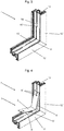
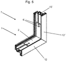
- FIGS. 3 to 5 The installation of the support element 1 according to the invention in a casement 7 is shown in FIGS. 3 to 5 in a sequence of perspective views of a corner area of a sash 7 of a window sash 8 ( Fig. 3 ), while ( Fig. 4 ) and after ( Fig. 5 ) the insertion of the carrier element 1 according to the invention shown.
- the corner area shown is in turn made up of the horizontally running profile section 12, which is geodetically lower in an installation situation, and the vertically running profile section 12 connected to it Profile section 12 'built up, with corresponding profile pieces of the plastic hollow chamber profile being mitred and welded together.
- Stiffening elements 13, 13 ' are pushed into the reinforcement chamber, the stiffening elements 13, 13' not extending all the way into the corners.
- the two grooves 15, 15 ' are dimensioned and spaced from one another in such a way that they are suitable for receiving the support elements 3, 3' formed as a pair of support rails and the engagement elements 4, 4 'formed as a pair of engagement rails.
- the contact sections 9, 9 'of the engagement elements 4, 4' are inserted into the grooves 15, 15 'on the side of the vertically running profile section 12' ( Fig. 4 ) and the support element 1 according to the invention is pushed into the corner area of the sash in a rotating manner until the contact sections 9, 9 'rest on the reinforcement element 13'. In this position, the support elements 3, 3 ′ also rest against the profile wall 14 of the lower profile section 12. This state is in Fig. 5 shown.
- the support element 1 according to the invention is fixed to the sash frame by means of fastening means (not shown) guided through the bores 16, 16 'of the vertically running profile section 12' and corresponding bores 6 'in the support element 2 of the support element 1, the fastening means being inserted into the reinforcing element 13'. of the vertically running profile section 12 'so that the weight of a surface element placed on the support element 2 of the support element 1 according to the invention does not only act on the lower profile section 12, but at least partially also on the reinforcement element 13' of the vertically running profile section 12 '.
- the wing 8 according to the invention rests against a frame via seals in the closed state of the window.
- the wing 8 according to the invention is rotatably mounted on the frame by means of fittings (not shown).
- the present invention has been described by way of example with reference to sashes of a window. It goes without saying that the present invention can also be correspondingly applied to door leaves.
Landscapes
- Engineering & Computer Science (AREA)
- Civil Engineering (AREA)
- Structural Engineering (AREA)
- Wing Frames And Configurations (AREA)
- Securing Of Glass Panes Or The Like (AREA)
Abstract
Die vorliegende Erfindung bezieht sich auf ein Trägerelement (1) zum Abstützen eines Flächenelements in einem Flügelrahmen (7) eines Fenster- oder Türflügels (8), wobei der Flügelrahmen (7) aus Profilabschnitten (12, 12') eines Hohlkammerprofils aufgebaut ist und in mindestens eine Hohlkammer des Hohlkammerprofils ein Verstärkungselement (13, 13') aufgenommen ist, wobei das Trägerelement (1) ein Auflageelement (2) zur Bereitstellung einer Auflagefläche für ein Flächenelement umfasst, wobei das Trägerelement (1) weiter mindestens ein Abstützelement (3, 3') zur Abstützung des Trägerelements (1) an einer Profilwand (14) eines Profilabschnitts (12) des Hohlkammerprofils sowie mindestens ein Eingriffselement (4, 4'), das mit dem Verstärkungselement (13') in Eingriff bringbar ist, das in eine Hohlkammer des Profilabschnitt (12') aufgenommen ist, der an den Profilabschnitt (12) angrenzt, an dessen einer Profilwand (14) sich das mindestens eine Abstützelement (3,3') abstützt, umfasst. Darüber hinaus bezieht sich die vorliegende Erfindung bezieht sich auf einen Fenster- oder Türflügel (8), der einen aus Abschnitten eines Hohlkammerprofils gebildeten Flügelrahmen (7); ein in eine Hohlkammer des Hohlkammerprofils aufgenommenes Verstärkungselement (13, 13'); ein in den Flügelrahmen (7) aufgenommenes Flächenelement; und mindestens ein erfindungsgemäßes Trägerelement (1) umfasst, wobei das mindestens eine Abstützelement (3, 3') zumindest abschnittweise an einer Profilwand (14) des geodätisch unteren Profilabschnitt (12) des Hohlkammerprofils anliegt und das mindestens eine Eingriffselement (4, 4') mit dem Verstärkungselement (13) in Eingriff steht, das in einer Hohlkammer eines an den geodätisch unteren Profilabschnitt (12) angrenzenden Profilabschnitts (12') des Hohlkammerprofils angeordnet ist.The present invention relates to a carrier element (1) for supporting a surface element in a sash frame (7) of a window or door sash (8), the sash frame (7) being constructed from profile sections (12, 12 ') of a hollow chamber profile and in a reinforcing element (13, 13 ') is received at least one hollow chamber of the hollow chamber profile, the carrier element (1) comprising a support element (2) for providing a support surface for a surface element, the carrier element (1) further at least one support element (3, 3 ') to support the carrier element (1) on a profile wall (14) of a profile section (12) of the hollow chamber profile and at least one engagement element (4, 4') which can be brought into engagement with the reinforcing element (13 ') which is in a hollow chamber of the profile section (12 ') which adjoins the profile section (12) on whose one profile wall (14) the at least one support element (3, 3') is supported. The present invention also relates to a window or door sash (8) which has a sash frame (7) formed from sections of a hollow chamber profile; a reinforcing element (13, 13 ') received in a hollow chamber of the hollow chamber profile; a surface element received in the casement (7); and comprises at least one support element (1) according to the invention, the at least one support element (3, 3 ') resting at least in sections on a profile wall (14) of the geodetically lower profile section (12) of the hollow chamber profile and the at least one engagement element (4, 4') is in engagement with the reinforcing element (13) which is arranged in a hollow chamber of a profile section (12 ') of the hollow chamber profile adjoining the geodetically lower profile section (12).
Description
Die vorliegende Erfindung betrifft ein Trägerelement zum Abstützen eines Flächenelements in einem Flügelrahmen eines Fenster- oder Türflügels, wobei der Flügelrahmen aus Profilabschnitten eines Hohlkammerprofils aufgebaut ist und in mindestens eine Hohlkammer des Hohlkammerprofils ein Verstärkungselement aufgenommen ist, wobei das Trägerelement ein Auflageelement zur Bereitstellung einer Auflagefläche für das Flächenelement umfasst. Darüber hinaus betrifft die vorliegende Erfindung einen Fenster- oder Türflügel, der ein erfindungsgemäßes Trägerelement umfasst.The present invention relates to a carrier element for supporting a surface element in a sash frame of a window or door sash, the sash frame being constructed from profile sections of a hollow chamber profile and a reinforcing element being received in at least one hollow chamber of the hollow chamber profile, the carrier element being a support element for providing a support surface for comprises the surface element. In addition, the present invention relates to a window or door sash which comprises a carrier element according to the invention.
Als derartige Trägerelemente werden im Stand der Technik Glasklotzbrücken eingesetzt, wie sie beispielsweise aus der
An dieser Stelle setzt die vorliegende Erfindung ein, der die Aufgabe zugrunde liegt, ein Trägerelement zum Abstützen eines Flächenelements in einem Flügelrahmen eines Fenster- oder Türflügels zur Verfügung zu stellen, das die Nachteile des Stands der Technik zumindest teilweise überwindet. Insbesondere soll die Gebrauchstauglichkeit eines das erfindungsgemäße Trägerelement umfassenden Fenster- oder Türflügels auch bei hohem Gewicht des Flächenelements gewährleistet sein. Darüber hinaus soll das Flächenelement ohne Verkleben in dem das erfindungsgemäße Trägerelement umfassenden Fenster- oder Türflügel gehalten werden können, ohne dass es zu einem Durchbiegen des Flügelrahmens aufgrund des Gewichts des Flächenelements kommen kann. Darüber hinaus liegt die Aufgabe der vorliegenden Erfindung in der Bereitstellung eines Fenster- oder Türflügels, der ein erfindungsgemäßes Trägerelement umfasst.This is where the present invention begins, which is based on the object of providing a carrier element for supporting a surface element in a casement of a window or door sash, which at least partially overcomes the disadvantages of the prior art. In particular, the usability of a window or door sash comprising the carrier element according to the invention should be ensured even with a high weight of the surface element. In addition, the surface element without gluing in the window or door sash comprising the carrier element according to the invention can be held, without the sash frame bending due to the weight of the planar element. In addition, the object of the present invention is to provide a window or door sash which comprises a carrier element according to the invention.
Diese und andere Aufgaben werden erfindungsgemäß durch ein Trägerelement zum Abstützen eines Flächenelements in einem Flügelrahmen eines Fenster- oder eines Türflügels mit den Merkmalen des Anspruchs 1 oder durch einen Fenster- oder Türflügel mit den Merkmalen des Anspruchs 7 gelöst. Bevorzugte Ausführungsformen der vorliegenden Erfindung sind in den abhängigen Ansprüchen beschrieben.These and other objects are achieved according to the invention by a carrier element for supporting a surface element in a sash frame of a window or a door sash with the features of
Gemäß der vorliegenden Erfindung wurde erkannt, dass die Durchbiegung des geodätisch unteren waagerechten Profilabschnitts des Flügelrahmens des Hohlkammerprofils aufgrund des Gewichts des Flächenelements dadurch reduziert werden kann, dass das Gewicht des Flächenelements zumindest teilweise auf einen anderen Profilholm übertragen wird. Erfindungsgemäß wird dies dadurch bewerkstelligt, dass das Trägerelement neben dem Auflageelement zur Bereitstellung einer Auflagefläche für das Flächenelement auch ein mindestens ein Abstützelement zur Abstützung des Trägerelements an einer Profilwand des Hohlkammerprofils sowie mindestens ein Eingriffselement umfasst. Das Eingriffselement kann mit dem Verstärkungselement eines benachbarten Profilabschnitts in Eingriff treten und so zumindest einen großen Teil der Gewichtskraft des Flächenelements auf diesen Profilabschnitt übertragen. Auf diese Weise ist die auf den geodätisch unteren Profilabschnitt einwirkende Gewichtskraft reduziert, so dass die Gefahr des Durchbiegens des geodätisch unteren Profilabschnittts verringert ist. Somit ist ein störungsfreies Öffnen und Schließen des Fensters insbesondere auch bei hohen Temperaturen gewährleistet. Ein Verkleben des Flächenelements in den Flügelrahmen ist nicht mehr erforderlich, was auch für eine bessere Rezyklierbarkeit des erfindungsgemäßen Fenster- oder Türflügel sorgt.According to the present invention, it was recognized that the deflection of the geodetically lower horizontal profile section of the sash of the hollow chamber profile can be reduced due to the weight of the surface element in that the weight of the surface element is at least partially transferred to another profile spar. According to the invention, this is achieved in that the carrier element comprises, in addition to the support element for providing a support surface for the surface element, at least one support element for supporting the carrier element on a profile wall of the hollow chamber profile and at least one engagement element. The engagement element can come into engagement with the reinforcement element of an adjacent profile section and thus transmit at least a large part of the weight of the surface element to this profile section. In this way, the weight acting on the geodetically lower profile section is reduced, so that the risk of the geodetically lower profile section bending over is reduced. Trouble-free opening and closing of the window is thus guaranteed, especially at high temperatures. It is no longer necessary to glue the surface element in the casement, which also ensures better recyclability of the window or door sash according to the invention.
Dementsprechend liegt die vorliegende Erfindung in der Bereitstellung eines Trägerelements zum Abstützen eines Flächenelements in einem Flügelrahmen eines Fenster- oder Türflügels, wobei der Flügelrahmen aus Profilabschnitten eines Hohlkammerprofils aufgebaut ist und in mindestens eine Hohlkammer des Hohlkammerprofils ein Verstärkungselement aufgenommen ist, wobei das Trägerelement ein Auflageelement zur Bereitstellung einer Auflagefläche für das Flächenelement umfasst, wobei sich das Trägerelement erfindungsgemäß dadurch auszeichnet, dass es weiter mindestens ein Abstützelement zur Abstützung des Trägerelements an einer Profilwand eines Profilabschnitts des Hohlkammerprofils sowie mindestens ein Eingriffselement, das mit dem Verstärkungselement in Eingriff bringbar ist, das in eine Hohlkammer des Profilabschnitts aufgenommen ist, der an den Profilabschnitt angrenzt, an dessen einer Profilwand sich das Abstützelement abstützt, umfasst. Darüber hinaus bezieht sich die vorliegende Erfindung auf einen Fenster- oder Türflügel, der einen aus Abschnitten eines Hohlkammerprofils gebildeten Flügelrahmen; ein in eine Hohlkammer des Hohlkammerprofils aufgenommenes Verstärkungselement; ein in den Flügelrahmen aufgenommenes Flächenelement; und mindestens ein erfindungsgemäßes Trägerelement umfasst, wobei das mindestens eine Abstützelement zumindest abschnittweise an einer Profilwand des geodätisch unteren Profilabschnitt des Hohlkammerprofils anliegt und das mindestens eine Eingriffselement mit dem Verstärkungselement in Eingriff steht, das in einer Hohlkammer eines an den geodätisch unteren Profilabschnitt angrenzenden Profilabschnitts des Hohlkammerprofils angeordnet ist.Accordingly, the present invention lies in the provision of a carrier element for supporting a surface element in a sash frame of a window or door sash, the sash frame being constructed from profile sections of a hollow chamber profile and a reinforcing element being received in at least one hollow chamber of the hollow chamber profile, the carrier element being a support element for Providing a support surface for the planar element, wherein the carrier element is characterized according to the invention in that it also has at least one support element for support of the carrier element on a profile wall of a profile section of the hollow chamber profile and at least one engagement element which can be brought into engagement with the reinforcing element, which is received in a hollow chamber of the profile section which adjoins the profile section on whose one profile wall the support element is supported. In addition, the present invention relates to a window or door sash which has a sash frame formed from sections of a hollow chamber profile; a reinforcing element received in a hollow chamber of the hollow chamber profile; a surface element received in the sash; and comprises at least one support element according to the invention, wherein the at least one support element rests at least in sections on a profile wall of the geodetically lower profile section of the hollow chamber profile and the at least one engagement element engages with the reinforcing element which is in a hollow chamber of a profile section of the hollow chamber profile adjoining the geodetically lower profile section is arranged.
Wie hierin verwendet bezieht sich der Begriff "Fenster- oder Türflügel" bevorzugt auf einen Flügel eines Kunststofffensters oder einer Kunststofftür. Es kommen aber auch Metallfenster oder Metalltüren sowie Verbundfenster und Verbundtüren in Betracht. Handelt es sich um den Flügel eines Kunststofffensters oder einer Kunststofftür, so ist als Hauptmaterial des Flügelprofils des erfindungsgemäßen Fenster- oder Türflügels Polyvinylchlorid (PVC), insbesondere Hart-PVC (PVC-U) oder glasfaserverstärktes PVC, dem zusätzlich Zusatzstoffe wie z. B. Stabilisatoren, Weichmacher, Pigmente und dergleichen zugesetzt sind, bevorzugt. PVC kann gut eingefärbt bzw. gefärbt werden und nimmt kaum Wasser auf.As used herein, the term “window or door sash” preferably refers to a sash of a plastic window or a plastic door. However, metal windows or metal doors as well as composite windows and composite doors are also possible. If it is the sash of a plastic window or a plastic door, the main material of the sash profile of the window or door sash according to the invention is polyvinyl chloride (PVC), in particular hard PVC (PVC-U) or glass fiber reinforced PVC, which also has additives such. B. stabilizers, plasticizers, pigments and the like are added, preferred. PVC can be dyed or dyed well and hardly absorbs water.
Hinsichtlich des erfindungsgemäßen Trägerelements kann es hilfreich sein, wenn das mindestens eine Eingriffselement als mindestens eine Eingriffsschiene, insbesondere als ein Paar von Eingriffsschienen, ausgebildet ist. Derartige als Schienen ausgebildete Einführungselemente lassen leicht in die relevante Position in dem Verstärkungselement bringen. Dabei kann es von besonderem Nutzen sein, wenn das/die Eingriffselement(e) mindestens einen Anlageabschnitt zur Anlage an einer Wand des Verstärkungselements aufweist/aufweisen. Bei einem einfachen Aufbau des mindestens einen Eingriffselements gewährleistet dies eine ausreichende Überleitung des Gewichts des Flächenelements in das Verstärkungselement des benachbarten Profilabschnitts.With regard to the carrier element according to the invention, it can be helpful if the at least one engagement element is designed as at least one engagement rail, in particular as a pair of engagement rails. Insertion elements of this type designed as rails can easily be brought into the relevant position in the reinforcement element. It can be of particular benefit if the engagement element (s) has / have at least one contact section for contact with a wall of the reinforcement element. With a simple construction of the at least one engagement element, this ensures sufficient transfer of the weight of the surface element into the reinforcement element of the adjacent profile section.
Es kann auch günstig sein, wenn das mindestens eine Abstützelement als mindestens eine Abstützschiene ausgebildet ist. Die Ausgestaltung des mindestens einen Abstützelements als Abstützschiene bietet einen einfachen und zuverlässigen Aufbau des erfindungsgemäßen Trägerelements. Dabei kann es von Vorteil sein, wenn das mindestens eine Abstützelement als ein Paar von Abstützschienen ausgebildet ist. So kann ein Verkippen des erfindungsgemäßen Trägerelements verhindert werden.It can also be advantageous if the at least one support element is designed as at least one support rail. The design of the at least one support element as a support rail offers a simple and reliable structure of the invention Support element. It can be advantageous if the at least one support element is designed as a pair of support rails. Tilting of the carrier element according to the invention can thus be prevented.
Für das Trägerelement kommen als bevorzugte Materialien polymere Werkstoffe, wie beispielsweise Polypropylen, Polyamide, Polyphenylsulfon (PPSU), Polyvinylidenfluorid (PVDF), Polyethersulfon (PES), Polysulfon (PSU), Polyphenylensulfid (PPS), AcrylnitrilButadien-Styrol-Copolymerisat (ABS), Polyoxymethylen (POM), Polyestercarbonat (PESC) und ASA (Acrylnitril-Styrol-Acrylester-Terpolymer), sowie Copolymere und Blends dieser Polymere, wobei diese Polymermaterialien auch faserverstärkt, insbesondere glasfaserverstärkt zum Einsatz kommen können, und/oder metallische Werkstoffe, wie beispielsweise Stahl, Edelstahl, Aluminium, Aluminium-Druckgusslegierungen, Zink-Druckgusslegierungen oder Aluminium-Zink-Druckgusslegierungen, und/oder Verbundmaterialien der genannten Werkstoffe, in Betracht.Preferred materials for the carrier element are polymeric materials, such as polypropylene, polyamides, polyphenylsulfone (PPSU), polyvinylidene fluoride (PVDF), polyethersulfone (PES), polysulfone (PSU), polyphenylene sulfide (PPS), acrylonitrile-butadiene-styrene copolymer (ABS), Polyoxymethylene (POM), polyester carbonate (PESC) and ASA (acrylonitrile-styrene-acrylic ester terpolymer), as well as copolymers and blends of these polymers, whereby these polymer materials can also be fiber-reinforced, in particular glass fiber-reinforced, and / or metallic materials such as steel , Stainless steel, aluminum, aluminum die-cast alloys, zinc die-cast alloys or aluminum-zinc die-cast alloys, and / or composite materials of the materials mentioned.
Es kann auch von Vorteil sein, wenn das erfindungsgemäße Trägerelement mehrteilig, insbesondere zweiteilig, ausgebildet ist. Beispielsweise ist es vorteilhaft, wenn das erfindungsgemäße Trägerelement ein Abdeckelement aufweist, das mit dem mindestens einem Eingriffselement verbindbar ist. Ein derartig ausgebildetes erfindungsgemäßes Trägerelement lässt sich leichter in einem Flügel montieren.It can also be advantageous if the carrier element according to the invention is designed in several parts, in particular in two parts. For example, it is advantageous if the carrier element according to the invention has a cover element that can be connected to the at least one engagement element. A carrier element according to the invention designed in this way can be more easily mounted in a wing.
In Bezug auf den erfindungsgemäßen Fenster- oder Türflügel kann es auch nützlich sein, wenn das Flächenelement als Isolierverglasung, vorzugsweise als Mehrscheibenisolierverglasung, ausgebildet ist. Isolierverglasungen weisen ein besonders hohes Gewicht des Flächenelements auf, so dass der Einsatz eines erfindungsgemäßen Trägerelements besonders günstig ist.With regard to the window or door sash according to the invention, it can also be useful if the surface element is designed as insulating glazing, preferably as multi-pane insulating glazing. Insulating glazing has a particularly high weight of the planar element, so that the use of a carrier element according to the invention is particularly favorable.
Es kann auch günstig sein, wenn wenigstens ein Glasklotz zwischen dem erfindungsgemäßen Trägerelement und dem Flächenelement angeordnet ist. Dadurch übernimmt das erfindungsgemäße Trägerelement die Funktion von Klotzbrücken, wodurch deren Anzahl im erfindungsgemäßen Flügel verringert werden kann.It can also be advantageous if at least one glass block is arranged between the carrier element according to the invention and the surface element. As a result, the support element according to the invention takes on the function of block bridges, whereby their number can be reduced in the wing according to the invention.
Bevorzugt ist das erfindungsgemäße Hohlkammerprofil aus Polyvinylchlorid (PVC) hergestellt, insbesondere aus Hart-PVC (PVC-U) oder glasfaserverstärktem PVC, das jeweils auch nachchloriertes PVC (PVC-C) enthalten kann. Besonders bevorzugt lässt sich das erfindungsgemäße Hohlkammerprofil in an sich bekannter Weise durch Extrusion oder Coextrusion herstellen.The hollow chamber profile according to the invention is preferably made from polyvinyl chloride (PVC), in particular from hard PVC (PVC-U) or glass fiber reinforced PVC, which can also contain post-chlorinated PVC (PVC-C). This can be particularly preferred Produce hollow chamber profile according to the invention in a known manner by extrusion or coextrusion.
Die Hohlkammerprofile werden bevorzugt zur Herstellung eines Flügels eines KunststoffFensters oder einer Kunststoff-Tür verwendet. Durch Verschweißen von auf Gehrung geschnittenen Abschnitten eines Kunststoff-Hohlkammerprofils kann ein Fenster- oder Türrahmen erhalten werden. Der erhaltene Fenster- oder Türrahmen ist für den Einbau in eine Öffnung einer Wandung eines Gebäudes vorgesehen bzw. in die Öffnung der Wandung eines Gebäudes einbaubar.The hollow chamber profiles are preferably used to manufacture a sash of a plastic window or a plastic door. A window or door frame can be obtained by welding together mitered sections of a plastic hollow chamber profile. The window or door frame obtained is intended for installation in an opening in a wall of a building or can be installed in the opening in the wall of a building.
Es kann auch hilfreich sein, wenn das Verstärkungselement aus einem metallischen Werkstoff, insbesondere Aluminium, Stahl oder Eisen, aus einem faserverstärkten polymeren Werkestoff, insbesondere einem glasfaserverstärkten polymeren Werkstoff, oder abschnittsweise aus einer Kombination der genannten Werkstoffe ausgebildet ist. Derartige Werkstoffe haben sich in der Praxis als besonders geeignet erwiesen.It can also be helpful if the reinforcement element is made from a metallic material, in particular aluminum, steel or iron, from a fiber-reinforced polymer material, in particular a glass fiber-reinforced polymer material, or in sections from a combination of the materials mentioned. Such materials have proven to be particularly suitable in practice.
In einem erfindungsgemäßen Flügel sind erfindungsgemäße Trägerelemente vorzugsweise in den beiden in einer Einbausitutation geodätisch unten angeordneten Ecken angeordnet, also in den Ecken des Flügelrahmens, an denen der geodätisch untere, horizontal verlaufende Profilabschnitt beteiligt ist. Ganz besonders ist ein erfindungsgemäßer Träger in der geodätisch unteren Ecke an der Seite angeordnet, auf der der erfindungsgemäße Flügel über Beschlagmittel drehbar gelagert an einem Blendrahmen festgelegt ist.In a wing according to the invention, carrier elements according to the invention are preferably arranged in the two corners geodetically arranged below in an installation situation, i.e. in the corners of the sash in which the geodetically lower, horizontally extending profile section is involved. In particular, a carrier according to the invention is arranged in the geodetically lower corner on the side on which the wing according to the invention is fixed to a frame by means of fittings so as to be rotatable.
Das erfindungsgemäße Trägerelement, der erfindungsgemäße Fenster- oder Türflügel sowie einzelne Teile davon können auch zeilenweise oder schichtweise unter Verwendung eines zeilenaufbauenden oder schichtaufbauenden Fertigungsverfahrens (z. B. 3D-Druck) hergestellt werden, bevorzugt ist jedoch die Herstellung des erfindungsgemäßen Trägerelements als Gussteil, des Hohlkammerprofils mittels Extrusion oder Coextrusion sowie des Verstärkungselements mittels Strangguss.The carrier element according to the invention, the window or door sash according to the invention and individual parts thereof can also be produced line by line or in layers using a line-building or layer-building manufacturing process (e.g. 3D printing), but production of the carrier element according to the invention as a cast part is preferred Hollow chamber profile by means of extrusion or coextrusion and the reinforcement element by means of continuous casting.
Im Folgenden soll die vorliegende Erfindung unter Bezugnahme auf die in den Figuren dargestellten Ausführungsformen im Detail erläutert werden. Dabei zeigen
Figur 1- eine perspektivische Ansicht eines Trägerelements gemäß einer Ausführungsform der vorliegenden Erfindung;
Figur 2- eine schematische Draufsicht auf einen Eckbereich eines das in
Fig. 1 gezeigte Trägerelements umfassenden Fensterflügels; Figur 3- eine perspektivische Ansicht eines Eckbereichs eines Flügelrahmens eines Fensterflügels vor dem Einsetzen eines Trägerelements gemäß einer weiteren Ausführungsform der vorliegenden Erfindung;
Figur 4- eine perspektivische Ansicht des in
Fig. 3 gezeigten Eckbereichs während des Einsetzens des inFig. 3 gezeigten erfindungsgemäßen Trägerelements; und - Figur 5
- eine perspektivische Ansicht des in
Fig. 3 und Fig. 4 gezeigten Eckbereichs nach dem Einsetzen erfindungsgemäßen Trägerelements gemäßFig. 3 .
- Figure 1
- a perspective view of a carrier element according to an embodiment of the present invention;
- Figure 2
- a schematic plan view of a corner region of the in
Fig. 1 shown support element comprising window sash; - Figure 3
- a perspective view of a corner region of a sash of a window sash before the insertion of a carrier element according to a further embodiment of the present invention;
- Figure 4
- a perspective view of the in
Fig. 3 corner area shown during the insertion of the inFig. 3 shown carrier element according to the invention; and - Figure 5
- a perspective view of the in
FIGS. 3 and 4 shown corner area after the insertion of the carrier element according to the inventionFig. 3 .
In
Eine Einbausituation des in
Der Einbau des erfindungsgemäßen Trägerelements 1 in einen Flügelrahmen 7 ist in
Der gezeigte Eckbereich ist wiederum aus dem in einer Einbausituation geodätisch unteren, horizontal verlaufenden Profilabschnitt 12 und dem damit verbundenen vertikal verlaufenden Profilabschnitt 12' aufgebaut, wobei entsprechende Profilstücke des Kunststoff-hohlkammerprofils auf Gehrung geschnitten und miteinander verschweißt wurden. In die Armierungskammer sind jeweils Versteifungselemente 13, 13' eingeschoben, wobei sich die Versteifungselemente 13, 13' jeweils nicht ganz bis in die Ecken erstrecken. In diesem Versteifungselement-freien Bereich des Flügelrahmens 7 sind zwei Nuten 15, 15' eingebracht. In den vertikal verlaufenden Profilabschnitt 12' sind zwei Bohrungen 16, 16' eingebracht, durch die wiederum Befestigungsmittel, insbesondere Schrauben, zur Befestigung des erfindungsgemäßen Trägerelements 1 am Flügelrahmen 7 geführt sein können. Die beiden Nuten 15, 15' sind dabei so dimensioniert und voneinander beabstandet, dass sie zur Aufnahme der als ein Paar von Abstützschienen ausgebildeten Abstützelemente 3, 3' und der als ein Paar von Eingriffsschienen ausgebildeten Eingriffselemente 4, 4' geeignet sind. Die Anlageabschnitte 9, 9' der Eingriffselemente 4, 4' werden auf der Seite des vertikal verlaufenden Profilabschnitts 12' in die Nuten 15, 15' eingesetzt (
In einem Fenster liegt der erfindungsgemäße Flügel 8 über Dichtungen im geschlossenen Zustand des Fensters an einem Blendrahmen an. Dabei ist der erfindungsgemäße Flügel 8 über Beschlagmittel (nicht dargestellt) drehbar gelagert am Blendrahmen festgelegt.In a window, the
Die vorliegende Erfindung wurde exemplarisch unter Bezugnahme auf Flügel eines Fensters beschrieben. Es versteht sich, dass die vorliegende Erfindung auch auf Türflügel entsprechend anwendbar ist.The present invention has been described by way of example with reference to sashes of a window. It goes without saying that the present invention can also be correspondingly applied to door leaves.
Claims (9)
dadurch gekennzeichnet, dass
das Trägerelement (1) weiter mindestens ein Abstützelement (3, 3') zur Abstützung des Trägerelements (1) an einer Profilwand (14) eines Profilabschnitts (12) des Hohlkammerprofils sowie mindestens ein Eingriffselement (4, 4'), das mit dem Verstärkungselement (13') in Eingriff bringbar ist, das in eine Hohlkammer des Profilabschnitt (12') aufgenommen ist, der an den Profilabschnitt (12) angrenzt, an dessen einer Profilwand (14) sich das mindestens eine Abstützelement (3,3') abstützt, umfasst.Carrier element (1) for supporting a surface element in a sash frame (7) of a window or door sash (8), the sash frame (7) being constructed from profile sections (12, 12 ') of a hollow chamber profile and a reinforcing element in at least one hollow chamber of the hollow chamber profile (13, 13 ') is received, wherein the carrier element (1) comprises a support element (2) for providing a support surface for a surface element,
characterized in that
the carrier element (1) further at least one support element (3, 3 ') for supporting the carrier element (1) on a profile wall (14) of a profile section (12) of the hollow chamber profile and at least one engagement element (4, 4') that connects to the reinforcing element (13 ') can be brought into engagement, which is accommodated in a hollow chamber of the profile section (12') which adjoins the profile section (12), on whose one profile wall (14) the at least one support element (3, 3 ') is supported , includes.
Applications Claiming Priority (1)
| Application Number | Priority Date | Filing Date | Title |
|---|---|---|---|
| DE202019106774.8U DE202019106774U1 (en) | 2019-12-05 | 2019-12-05 | Carrier element for supporting a surface element in a sash frame of a window or door sash and a window or door sash encompassing this |
Publications (3)
| Publication Number | Publication Date |
|---|---|
| EP3832063A1 true EP3832063A1 (en) | 2021-06-09 |
| EP3832063B1 EP3832063B1 (en) | 2024-03-06 |
| EP3832063C0 EP3832063C0 (en) | 2024-03-06 |
Family
ID=73654664
Family Applications (1)
| Application Number | Title | Priority Date | Filing Date |
|---|---|---|---|
| EP20210893.2A Active EP3832063B1 (en) | 2019-12-05 | 2020-12-01 | Support element for supporting a flat element in a leaf frame of a window or door leaf and this complete window or door leaf |
Country Status (2)
| Country | Link |
|---|---|
| EP (1) | EP3832063B1 (en) |
| DE (1) | DE202019106774U1 (en) |
Citations (5)
| Publication number | Priority date | Publication date | Assignee | Title |
|---|---|---|---|---|
| DE8703052U1 (en) | 1987-02-27 | 1987-07-09 | Grundmeier KG, 4835 Rietberg | Glass block |
| DE3923288A1 (en) | 1989-07-14 | 1991-02-07 | Deflex Dichtsysteme Gmbh | Glazing joints and inserts - are mfd. with multiple configuration or uses and engaged conical shaped supports |
| DE29807020U1 (en) * | 1998-03-27 | 1998-08-06 | Herbes, Wilhelm, 49774 Lähden | Window sash and blocking element for use in a window sash |
| US20060254150A1 (en) * | 2005-05-13 | 2006-11-16 | Van Kirk William R | Apparatus for supporting glass in a window assembly |
| AT509673A1 (en) * | 2010-03-24 | 2011-10-15 | Pfisterer Rudolf | WING FOR A WINDOW OR DOOR |
Family Cites Families (4)
| Publication number | Priority date | Publication date | Assignee | Title |
|---|---|---|---|---|
| DE3213176A1 (en) * | 1982-04-08 | 1983-10-13 | Arnold 7918 Illertissen Butzbach | Insulating-glass window |
| DE19925495A1 (en) * | 1999-06-04 | 2000-12-07 | Peter Willrich | Security insert part to fix window pane in window frame has horizontal support surface under frame with support bars under vertical support surface and is made of hard-to-cut material, such as steel |
| DE102018106525A1 (en) * | 2018-03-20 | 2019-09-26 | PHI Technik für Fenster und Türen GmbH | joint assembly |
| DE202018106077U1 (en) * | 2018-10-24 | 2018-11-07 | SCHÜCO International KG | Glass carrier construction and frame construction |
-
2019
- 2019-12-05 DE DE202019106774.8U patent/DE202019106774U1/en active Active
-
2020
- 2020-12-01 EP EP20210893.2A patent/EP3832063B1/en active Active
Patent Citations (5)
| Publication number | Priority date | Publication date | Assignee | Title |
|---|---|---|---|---|
| DE8703052U1 (en) | 1987-02-27 | 1987-07-09 | Grundmeier KG, 4835 Rietberg | Glass block |
| DE3923288A1 (en) | 1989-07-14 | 1991-02-07 | Deflex Dichtsysteme Gmbh | Glazing joints and inserts - are mfd. with multiple configuration or uses and engaged conical shaped supports |
| DE29807020U1 (en) * | 1998-03-27 | 1998-08-06 | Herbes, Wilhelm, 49774 Lähden | Window sash and blocking element for use in a window sash |
| US20060254150A1 (en) * | 2005-05-13 | 2006-11-16 | Van Kirk William R | Apparatus for supporting glass in a window assembly |
| AT509673A1 (en) * | 2010-03-24 | 2011-10-15 | Pfisterer Rudolf | WING FOR A WINDOW OR DOOR |
Also Published As
| Publication number | Publication date |
|---|---|
| DE202019106774U1 (en) | 2021-03-08 |
| EP3832063B1 (en) | 2024-03-06 |
| EP3832063C0 (en) | 2024-03-06 |
Similar Documents
| Publication | Publication Date | Title |
|---|---|---|
| DE202019107047U1 (en) | Window or door sash as well as this comprehensive window or this comprehensive door | |
| EP2363567B1 (en) | Frame of a plastic window or a plastic door | |
| DE1509553A1 (en) | Window construction | |
| DE19963233A1 (en) | Frame for windows or doors | |
| EP0833998B1 (en) | Window casement hollow section and window casement made of such section for windows with two wings | |
| EP3832063B1 (en) | Support element for supporting a flat element in a leaf frame of a window or door leaf and this complete window or door leaf | |
| EP4198244A1 (en) | Window or door leaf, blind frame and window or door comprising same | |
| DE3503314A1 (en) | Strand-shaped profile seal made of elastic material | |
| EP4083366A1 (en) | Wing for a window or a door, glass securing element for such a wing, window comprising same and door comprising same | |
| EP3670808B1 (en) | Frame assembly for a door or window | |
| EP3828372B1 (en) | Window or door leaf and window or door comprising same | |
| DE202020107305U1 (en) | window | |
| DE102019131361A1 (en) | Reinforcement element for window or door cavity profiles as well as method for reinforcing a window or door cavity profile | |
| EP2428633B1 (en) | Blind frame profile for door, window or facade structure | |
| EP2942467B1 (en) | Door with a handle profile | |
| EP3828373A1 (en) | Window or door leaf and window or door comprising the same | |
| DE202013103305U1 (en) | Wing-covering door | |
| DE10021332A1 (en) | Window or door frame has inner and outer profiles joined by connecting elements and fixture arm | |
| EP4390038A1 (en) | Wing for a window or a door, window comprising same and door comprising same | |
| DE20313884U1 (en) | Window or door frame is made up of hollow metal profiles containing rigid polyurethane foam cores with mesh reinforcement | |
| DE2026947A1 (en) | Metal construction, in particular for the production of inserts, fastenings and the like in buildings | |
| EP4015759A1 (en) | Sliding window or sliding door | |
| DE202020107327U1 (en) | Casement for a window or a door, this enclosing window as well as this enclosing door | |
| DE202020107294U1 (en) | Sash for a window or a door, sash profile for forming a sash and connection comprising such a sash | |
| DE2530035A1 (en) | ENCLOSURE FOR WALL OPENINGS IN BUILDINGS |
Legal Events
| Date | Code | Title | Description |
|---|---|---|---|
| PUAI | Public reference made under article 153(3) epc to a published international application that has entered the european phase |
Free format text: ORIGINAL CODE: 0009012 |
|
| STAA | Information on the status of an ep patent application or granted ep patent |
Free format text: STATUS: THE APPLICATION HAS BEEN PUBLISHED |
|
| AK | Designated contracting states |
Kind code of ref document: A1 Designated state(s): AL AT BE BG CH CY CZ DE DK EE ES FI FR GB GR HR HU IE IS IT LI LT LU LV MC MK MT NL NO PL PT RO RS SE SI SK SM TR |
|
| STAA | Information on the status of an ep patent application or granted ep patent |
Free format text: STATUS: REQUEST FOR EXAMINATION WAS MADE |
|
| 17P | Request for examination filed |
Effective date: 20211207 |
|
| RBV | Designated contracting states (corrected) |
Designated state(s): AL AT BE BG CH CY CZ DE DK EE ES FI FR GB GR HR HU IE IS IT LI LT LU LV MC MK MT NL NO PL PT RO RS SE SI SK SM TR |
|
| RAP1 | Party data changed (applicant data changed or rights of an application transferred) |
Owner name: REHAU INDUSTRIES SE & CO. KG |
|
| RAP3 | Party data changed (applicant data changed or rights of an application transferred) |
Owner name: REHAU INDUSTRIES SE & CO. KG |
|
| GRAP | Despatch of communication of intention to grant a patent |
Free format text: ORIGINAL CODE: EPIDOSNIGR1 |
|
| STAA | Information on the status of an ep patent application or granted ep patent |
Free format text: STATUS: GRANT OF PATENT IS INTENDED |
|
| INTG | Intention to grant announced |
Effective date: 20230918 |
|
| GRAS | Grant fee paid |
Free format text: ORIGINAL CODE: EPIDOSNIGR3 |
|
| GRAA | (expected) grant |
Free format text: ORIGINAL CODE: 0009210 |
|
| STAA | Information on the status of an ep patent application or granted ep patent |
Free format text: STATUS: THE PATENT HAS BEEN GRANTED |
|
| AK | Designated contracting states |
Kind code of ref document: B1 Designated state(s): AL AT BE BG CH CY CZ DE DK EE ES FI FR GB GR HR HU IE IS IT LI LT LU LV MC MK MT NL NO PL PT RO RS SE SI SK SM TR |
|
| REG | Reference to a national code |
Ref country code: CH Ref legal event code: EP |
|
| REG | Reference to a national code |
Ref country code: DE Ref legal event code: R096 Ref document number: 502020007230 Country of ref document: DE |
|
| REG | Reference to a national code |
Ref country code: IE Ref legal event code: FG4D Free format text: LANGUAGE OF EP DOCUMENT: GERMAN |
|
| U01 | Request for unitary effect filed |
Effective date: 20240404 |
|
| U07 | Unitary effect registered |
Designated state(s): AT BE BG DE DK EE FI FR IT LT LU LV MT NL PT SE SI Effective date: 20240412 |
|
| PG25 | Lapsed in a contracting state [announced via postgrant information from national office to epo] |
Ref country code: GR Free format text: LAPSE BECAUSE OF FAILURE TO SUBMIT A TRANSLATION OF THE DESCRIPTION OR TO PAY THE FEE WITHIN THE PRESCRIBED TIME-LIMIT Effective date: 20240607 |
|
| PG25 | Lapsed in a contracting state [announced via postgrant information from national office to epo] |
Ref country code: RS Free format text: LAPSE BECAUSE OF FAILURE TO SUBMIT A TRANSLATION OF THE DESCRIPTION OR TO PAY THE FEE WITHIN THE PRESCRIBED TIME-LIMIT Effective date: 20240606 Ref country code: HR Free format text: LAPSE BECAUSE OF FAILURE TO SUBMIT A TRANSLATION OF THE DESCRIPTION OR TO PAY THE FEE WITHIN THE PRESCRIBED TIME-LIMIT Effective date: 20240306 |
|
| PG25 | Lapsed in a contracting state [announced via postgrant information from national office to epo] |
Ref country code: ES Free format text: LAPSE BECAUSE OF FAILURE TO SUBMIT A TRANSLATION OF THE DESCRIPTION OR TO PAY THE FEE WITHIN THE PRESCRIBED TIME-LIMIT Effective date: 20240306 |
|
| PG25 | Lapsed in a contracting state [announced via postgrant information from national office to epo] |
Ref country code: RS Free format text: LAPSE BECAUSE OF FAILURE TO SUBMIT A TRANSLATION OF THE DESCRIPTION OR TO PAY THE FEE WITHIN THE PRESCRIBED TIME-LIMIT Effective date: 20240606 Ref country code: NO Free format text: LAPSE BECAUSE OF FAILURE TO SUBMIT A TRANSLATION OF THE DESCRIPTION OR TO PAY THE FEE WITHIN THE PRESCRIBED TIME-LIMIT Effective date: 20240606 Ref country code: HR Free format text: LAPSE BECAUSE OF FAILURE TO SUBMIT A TRANSLATION OF THE DESCRIPTION OR TO PAY THE FEE WITHIN THE PRESCRIBED TIME-LIMIT Effective date: 20240306 Ref country code: GR Free format text: LAPSE BECAUSE OF FAILURE TO SUBMIT A TRANSLATION OF THE DESCRIPTION OR TO PAY THE FEE WITHIN THE PRESCRIBED TIME-LIMIT Effective date: 20240607 Ref country code: ES Free format text: LAPSE BECAUSE OF FAILURE TO SUBMIT A TRANSLATION OF THE DESCRIPTION OR TO PAY THE FEE WITHIN THE PRESCRIBED TIME-LIMIT Effective date: 20240306 |