EP3831990A1 - Spinning-pattern setting apparatus of spinning machine - Google Patents
Spinning-pattern setting apparatus of spinning machine Download PDFInfo
- Publication number
- EP3831990A1 EP3831990A1 EP20207382.1A EP20207382A EP3831990A1 EP 3831990 A1 EP3831990 A1 EP 3831990A1 EP 20207382 A EP20207382 A EP 20207382A EP 3831990 A1 EP3831990 A1 EP 3831990A1
- Authority
- EP
- European Patent Office
- Prior art keywords
- data
- pictorial
- slub
- pattern
- parameters
- Prior art date
- Legal status (The legal status is an assumption and is not a legal conclusion. Google has not performed a legal analysis and makes no representation as to the accuracy of the status listed.)
- Granted
Links
Images



Classifications
-
- D—TEXTILES; PAPER
- D01—NATURAL OR MAN-MADE THREADS OR FIBRES; SPINNING
- D01H—SPINNING OR TWISTING
- D01H1/00—Spinning or twisting machines in which the product is wound-up continuously
-
- D—TEXTILES; PAPER
- D01—NATURAL OR MAN-MADE THREADS OR FIBRES; SPINNING
- D01H—SPINNING OR TWISTING
- D01H13/00—Other common constructional features, details or accessories
- D01H13/32—Counting, measuring, recording or registering devices
-
- G—PHYSICS
- G06—COMPUTING OR CALCULATING; COUNTING
- G06F—ELECTRIC DIGITAL DATA PROCESSING
- G06F30/00—Computer-aided design [CAD]
- G06F30/10—Geometric CAD
-
- G—PHYSICS
- G06—COMPUTING OR CALCULATING; COUNTING
- G06F—ELECTRIC DIGITAL DATA PROCESSING
- G06F2113/00—Details relating to the application field
- G06F2113/12—Cloth
Definitions
- the present invention relates to a spinning-pattern setting apparatus of a spinning machine.
- apparatuses of operating and programming ring spinning machines are known, for example.
- Such apparatuses include an apparatus of operating and programming a ring spinning machine as disclosed in Japanese Patent Application Publication No. 2013-529728 .
- the apparatus disclosed in the above Application Publication includes an actuation device configured to operate a driving means in response to a speed instruction, and an electronic programming device configured to generate programs for setting the progress of a count and/or twists along the length of a yarn.
- the electronic programming device includes a first interface suitable for designing the profile of a slub, and a conversion means suitable for converting parameters of the designed profile of the slub into the speed instruction for the actuation device.
- the electronic programming device also includes a second interface suitable for programming repetition along the yarn of a plurality of slubs designed with the first interface.
- This type of apparatuses may display, for example, a blackboard pictorial image or a fabric pattern pictorial image generated in a simulation based on slub-pattern data set for the spinning machine.
- the blackboard pictorial image represents a slub yarn wound around the blackboard, which is generated in the simulation
- the fabric pattern pictorial image represents a fabric woven by the slub yarn spun based on the slub-pattern data, which is generated in the simulation.
- the slub-pattern data is to be fixed after parameters of all the slubs are entered, then the fixed slub-pattern data is to be read by a simulator, and the pictorial image is to be generated in the simulation by the simulator.
- the blackboard pictorial image or the fabric pattern pictorial image displayed has some undesired factors in a design and thus the slub-pattern data is intended to be changed
- parameters that may affect the undesired factors in the design are to be modified based on the presumption
- the slub-pattern data is to be fixed, and then the fixed slub-pattern data is to be read by the simulator to redisplay the simulated pictorial image. If the redisplayed pictorial image yet has some undesired factors in the design, modifying parameters, fixing the slub-pattern data, reading the fixed slub-pattern data by the simulator, and displaying the pictorial image are to be repeated until the displayed pictorial image matches an intended design.
- This parameter setting operation is complicated and takes a great time.
- the present invention has been made in response to the above issue and is to provide a spinning-pattern setting apparatus of a spinning machine which is capable of setting a spinning pattern in a reduced time based on pictorial data generated based on spinning-pattern data.
- a spinning-pattern setting apparatus of a spinning machine that includes a parameter input unit used for entering a plurality of parameters of a yarn to be spun by the spinning machine, a pattern-data generation unit configured to generate pattern data from the parameters entered via the parameter input unit, a pictorial-data generation unit configured to generate pictorial data based on the pattern data generated by the pattern-data generation unit, and a display unit configured to display the pictorial data generated by the pictorial-data generation unit.
- the pattern-data generation unit is configured to automatically generate the pattern data without depending on an instruction by an operator.
- the pictorial-data generation unit is configured to generate, every time the pattern data is generated, the pictorial data so that the pictorial data is updated and redisplayed in the display unit.
- a spinning-pattern setting apparatus of a spinning machine according to a first embodiment of the present invention with reference to the accompanying drawings.
- the embodiment disclosed herein is described by taking an example of a slub-pattern setting apparatus of a spinning machine, capable of setting a slub pattern corresponding to a spinning pattern (hereinafter referred to as merely a "slub-pattern setting apparatus").
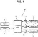
- a slub-pattern setting apparatus 10 includes a control device 11, a program memory 12, an operation memory 13, an input unit 14, an input interface 15, an output interface 16, a display unit 17, and a data output unit 18.
- the control device 11 includes a CPU (not shown) that executes various programs.
- the control device 11 is connected to the program memory 12 and the operation memory 13.
- the control device 11 is also connected to the input unit 14 via the input interface 15, and to the display unit 17 via the output interface 16.
- the control device 11 serves as a pattern-data generation unit configured to generate slub-pattern data corresponding to spinning-pattern data.
- the program memory 12 is a ROM, i.e., a read-only memory, configured to store various programs and data to be used for executing the programs.
- the various programs include a slub-pattern-data generating program for generating the slub-pattern data from parameters of slub yarns, and a display program for the display unit 17 displaying a pictorial image corresponding to pictorial data generated in a simulation based on the slub-pattern data.
- the control device 11 also serves as a pictorial-data generation unit configured to generate the pictorial data based on pattern data. In other words, the control device 11 serves as a simulation unit configured to generate the pictorial image, corresponding to the pictorial data, in the simulation based on the slub-pattern data generated by the pattern-data generation unit.
- the operation memory 13 is a RAM, i.e., a random-access memory, configured to read out and rewrite data, and temporarily stores data entered via the input unit 14 and results processed by the control device 11. Specifically, the operation memory 13 is configured to store the parameters of the slub yarns entered via the input unit 14, the slub-pattern data generated by the control device 11, and the data of the pictorial images of the slub yarns generated in the simulation based on the slub-pattern data.
- the input unit 14 serves as a parameter input unit, which is specifically a keyboard. An operator operates the input unit 14 to enter the parameters of the slub yarns such as a pitch (mm), a length (mm), and a slub thickness (%).
- the input unit 14 is also used for entering various other data.
- the pitch refers to a length of an interval between any two adjacent slubs.
- the length refers to a length of the slub.
- the slub thickness refers to a thickness of the slub expressed as a percentage of the thickness of the slub to a reference thickness of the slub yarn, where the reference thickness of the slub yarn refers to a thickness of the pitch portion of the slub yarn, i.e., a thickness of the slub yarn at the interval between any two adjacent slubs. In other words, the slub thickness is set to exceed 100%.
- the data entered via the input unit 14 is transferred to the control device 11 via the input interface 15.
- the input unit 14 may be a touch panel, instead of the keyboard, integrated with a display screen so as to have both a display function and an input function.
- the display unit 17 such as a liquid crystal display, is configured to display various data and the pictorial data.
- the display unit 17 is connected to the control device 11 via the output interface 16.
- a display screen 19 of the display unit 17 displays a parameter input window 20.
- the display screen 19 also displays the pictorial image such as a slub image window 21 and a fabric image window 22.
- FIG. 2 shows only the parameter input window 20 and the slub image window 21, but not the fabric image window 22.
- the slub image window 21 and the fabric image window 22 correspond to the pictorial images.
- the data output unit 18 is connected to the control device 11 via the output interface 16.
- the data output unit 18 is an external storage medium such as a USB memory, used for retrieving data and programs from the operation memory 13.
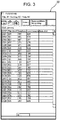
- the parameter input window 20 serves as a parameter input panel, and is a window that displays the parameters of the slub yarns.
- the parameters are used for determining the slub pattern that is used by the spinning machine for spinning the slub yarn.
- the parameter input window 20 displays the parameters entered via the input unit 14.
- the slub pattern is determined by entering the parameters of the slub yarn, i.e., the pitch (mm), the length (mm), and the slub thickness (%), for each step for spinning the slub yarn. In the present embodiment, a maximum of thousand steps is available for the entry of the parameters that determine the slub patterns.
- the parameters entered and displayed in the parameter input window 20 are transferred to the control device 11. Every time the parameters are entered, the parameters are transferred to the control device 11, and the control device 11 generates the slub-pattern data.
- the slub image window 21 corresponds to the pictorial image generated in the simulation based on the slub-pattern data generated from the entered parameters.
- the slub image window 21 schematically shown in FIG. 2 displays a state of the slub yarn wound around a blackboard, which is generated in the simulation by the control device 11 based on the slub-pattern data.
- the slub image window 21 displays the pictorial image of the slub yarn that is spun in the simulation.
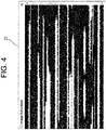
- FIG. 4 an illustrative example of the slub image window 21 is shown.
- white portions represent the slub yarn wound around the blackboard and black portions represent the blackboard seen through the wound slub yarn.
- the slub yarn displayed as the white portions extends in the lengthwise direction and is arranged in the transverse direction to the lengthwise direction.
- a window for setting (not shown), i.e., a window other than the parameter input window 20, is used.
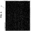
- FIG. 5 Another pictorial image of the data generated in the simulation is also displayed in the fabric image window 22 shown in FIG. 5 , in addition to the slub image window 21 that displays the slub yarn generated in the simulation.
- the fabric image window 22 displays the pictorial image of fabric woven by the slub yarn, which is generated in the simulation. Referring to FIG. 5 , an illustrative example of the fabric image window 22 is shown.
- the fabric image window 22 displays weft yarns of the slub yarns generated in the simulation.
- the fabric image window 22 may display a fabric image corresponding to types of weaves such as a plain weave and a twill weave.
- the slub yarns extend in the lengthwise direction and the warp yarns extend in the transverse direction to the lengthwise direction.
- a window for setting (not shown), i.e., a window other than the parameter input window 20, is used.
- a first display state and a second display state are selectively switchable: the first display state includes the slub image window 21 together with the parameter input window 20, whereas the second display state includes the fabric image window 22 together with the parameter input window 20.
- the slub-pattern data is determined by entering the parameters of the slub yarn for each step.
- the entered parameters are transferred to the control device 11 serving as the pattern-data generation unit, and the control device 11 generates the slub-pattern data from the entered parameters.
- the generated slub-pattern data is transferred to the control device 11 serving as the simulation unit, and the control device 11 generates slub image data or fabric image data generated in the simulation based on the slub-pattern data.
- the display unit 17 displays one of the pictorial images generated based on the slub image data and the fabric image data generated by the control device 11.
- the pictorial images correspond to the slub image window 21 and the fabric image window 22.
- a predetermined updating time elapses periodically in Step S01. Then, the control device 11 outputs the slub-pattern data generated from the parameters entered at that point of time into a pattern data file to update the pattern data file in Step S02.
- the pattern data file is automatically updated every time the predetermined updating time elapses, without depending on an instruction by the operator.
- the slub-pattern data generated from the changed parameters is reflected on the pattern data file so that the pattern data file is updated.
- the predetermined updating time is set in the unit of seconds (e.g. 10 sec.).
- the predetermined updating time is enabled to be changed in a window for setting, i.e., a window other than the parameter input window 20.
- the control device 11 then generates the slub image data and the fabric image data generated in the simulation based on the pattern data file that is updated every time the predetermined updating time elapses, and updates and redisplays the pictorial image displayed in the display screen 19 in Step S03. Specifically, the slub image window 21 and the fabric image window 22 displayed in the display screen 19 are updated and redisplayed.
- the pattern data file is periodically updated regardless of the presence or absence of any change in the parameters of the slub yarn.
- the pictorial image is updated and redisplayed by reflecting any change in the parameters if the change is made within the predetermined updating time, while no change is made in the pictorial image even if updating is performed when no change is made in the parameters within the predetermined updating time.
- the operator activates the slub-pattern setting apparatus 10.
- the activation allows the slub-pattern setting apparatus 10 to display either the slub image window 21 or the fabric image window 22 in the display screen 19 of the display unit 17, in addition to the parameter input window 20.
- the operator operates the slub-pattern setting apparatus 10 to display the parameter input window 20 in the display screen 19, and operates the input unit 14 to enter the parameters used for determining the slub-pattern data. Specifically, entering the pitch (mm), the length (mm), and the slub thickness (%) is repeated in each step. The entered parameters are displayed in the parameter input window 20.
- the slub-pattern data is output into the pattern data file, and the slub image data and the fabric image data are generated based on the pattern data file and shown as the pictorial images.
- the operator checks the slub image window 21 and the fabric image window 22 displayed in the display screen 19 to determine whether to fix the slub pattern.
- the slub-pattern data is automatically output into the pattern data file every time the predetermined updating time elapses even in the middle of the slub-pattern data being edited.
- the slub image data and the fabric image data are generated based on the generated pattern data file, and the pictorial images generated based on the slub image data and the fabric image data are updated and redisplayed.
- the slub image window 21 and the fabric image window 22 are updated and redisplayed based on the slub-pattern data under being edited.
- the operator checks the pictorial images in the slub image window 21 and the fabric image window 22 in the middle of editing the slub-pattern data, and then fixes the final slub-pattern data.
- the slub-pattern data is allowed to be changed by changing some of the parameters even after the slub-pattern data is fixed.
- the operator downloads the fixed pattern data file from the data output unit 18 into the external storage medium such as the USB memory, and then enters the fixed pattern data file into the spinning machine (not shown).
- the spinning machine spins the slub yarn based on the fixed slub-pattern data.
- the following will describe a spinning-pattern setting apparatus of a spinning machine according to a second embodiment of the present invention with reference to the accompanying drawings.
- the second embodiment is different from the first embodiment in that distribution-graph pictorial data corresponding to the pictorial data is displayed in the display unit.
- descriptions of components identical with those of the first embodiment described above will be omitted or simplified by providing the identical reference numerals as those of the first embodiment.
- the display screen 19 of the display unit 17 of the second embodiment displays a distribution-graph pictorial data window 31 corresponding to the pictorial data, in addition to the parameter input window 20. It should be noted that the display screen 19 is configured to display the slub image window 21 and the fabric image window 22, in addition to the distribution-graph pictorial data window 31, although these windows are not shown in FIG. 7 .
- the distribution-graph pictorial data window 31 is the pictorial data that visually shows a distribution of the slub patterns based on the slub-pattern data generated from the entered parameters. Referring to FIG. 8 , an illustrative example of the distribution-graph pictorial data window 31 is shown.
- the distribution-graph pictorial data window 31 shown in FIG. 8 includes a range input field 32, a distribution-graph display field 33, and a numerical value display field 34.
- the range input field 32 is used for specifying ranges of the thickness (%) and length (mm), i.e., the parameters of the slub yarn.
- the range input field 32 includes input boxes 32A and 32B for specifying the range of the thickness (%).
- the range input field 32 also includes input boxes 32C and 32D for specifying the range of the length (mm).
- the range input field 32 also includes an OK button 32E used for fixing the entered ranges of thickness (%) and length (mm), and a FULL button 32F used for specifying the maximum ranges of thickness (%) and length (mm).
- the distribution-graph display field 33 includes a length cell group in a horizontal axis, a thickness cell group in a vertical axis, and a number-of-yarns cell group of the rest of the cells arranged in a matrix.
- the length cell group includes a plurality of length cells 33A.
- Each of the length cells 33A shows the length (mm), i.e., the parameter of the slub yarn.
- the plurality of the length cells 33A (ten cells) showing the length (mm) is arranged in the horizontal direction in the distribution-graph display field 33.
- the length cells 33A show values of the lengths (mm), i.e., the parameters of the slub yarn, within the range of the length (mm) specified in the range input field 32.
- the values shown in the plurality of the length cells 33A increase in the order from left to right.
- the thickness cell group includes a plurality of thickness cells 33B.
- Each of the thickness cells 33B shows the thickness (%), i.e., the parameter of the slub yarn.
- the plurality of the thickness cells 33B (ten cells) showing the thickness (%) is arranged in the vertical direction in the distribution-graph display field 33.
- the thickness cell 33B show values of the thicknesses (%), i.e., the parameters of the slub yarn, within the range of the thickness (%) specified in the range input field 32.
- the values shown in the plurality of the thickness cells 33B increase in the order from bottom to top.
- the number-of-yarns cell group includes a plurality of number-of-yarns cells 33C arranged in the matrix.
- the number of the number-of-yarns cells 33C of the number-of-yarns cell group is a hundred (10 x 10).
- Each of the number-of-yarns cells 33C shows the number of the slub yarns specified by the length (mm) in the corresponding length cell 33A and the thickness (%) in the corresponding thickness cell 33B. Lightness of the background of the number-of-yarns cell 33C gradually decreases as the value of the number of the slub yarns shown in the number-of-yarns cell 33C increases.
- the numerical value display field 34 is a table indicating the minimum value, the average value, and the maximum value of each of the thickness (%) and the length (mm) that are displayed in the distribution-graph pictorial data window 31.
- the distribution-graph display field 33 of the second embodiment is a graph of distribution of the number of the slub yarns specified by the thicknesses (%) and the lengths (mm), in which the plurality of the number-of-yarns cells 33C is arranged in the matrix with the plurality of length cells 33A in the horizontal axis and the plurality of thickness cells 33B in the vertical axis.
- the distribution-graph pictorial data window 31 is displayed together with the parameter input window 20, by the display program.
- the first display state, the second display state, and a third display state are selectively switchable: the first display state includes the slub image window 21 together with the parameter input window 20, the second display state includes the fabric image window 22 together with the parameter input window 20, and the third display state includes the distribution-graph pictorial data window 31 together with the parameter input window 20.
- the control device 11 generates the slub-pattern data from the parameters, and generates the distribution-graph pictorial data based on the slub-pattern data.
- the display unit 17 displays the distribution-graph pictorial data window 31 serving as the distribution-graph pictorial data corresponding to the pictorial data, generated by the control device 11.
- Step S11 a procedure for updating and redisplaying the distribution-graph pictorial data window 31 is shown.
- the control device 11 reflects the parameters entered at that point of time on the slub-pattern data, and outputs the slub-pattern data into the pattern data file to update the pattern data file in Step S12.
- the pattern data file is automatically updated without depending on the instruction by the operator.
- the slub-pattern data generated from the changed parameters is reflected on the pattern data file so that the pattern data file is updated.
- the control device 11 updates the distribution-graph pictorial data window 31 that is displayed in the display screen 19, in Step S13.
- the pattern data file is updated every time any of the parameters of the slub yarn is changed.
- the distribution-graph pictorial data window 31 is updated and redisplayed by reflecting any change in the parameters, whereas the distribution-graph pictorial data window 31 is not updated when no change is made in the parameters.
- the control device 11 upon any change in the parameters of the slub yarn, compares the slub-pattern data before and after the change, and updates only the cells, of the distribution-graph display field 33, affected by the difference in the slub-pattern data.
- the control device 11 does not update the distribution-graph pictorial data window 31, even if some change is made in the parameters of the slub yarn, unless the change causes the distribution-graph display field 33 to have some change that is identified by comparing the slub-pattern data before and after the change in the parameters.
- the control device 11 is configured to automatically generate the pattern data without depending on the instruction by the operator upon some change in the parameters. Every time the pattern data is generated, the control device 11 generates and updates the distribution-graph pictorial data window 31 to be redisplayed in the display unit 17. The operator is enabled to check the distribution-graph pictorial data window 31 generated based on the pattern data under editing, which allows the operator to identify how the distribution-graph pictorial data window 31 changes by the change in the parameters in real time. The operator is enabled to visually check the distribution of the slub yarns by checking the distribution-graph pictorial data window 31.
- the operator is enabled to intuitively recognize the difference between the number-of-yarns cells 33C showing large values and the number-of-yarns cells 33C showing small values by the difference in the lightness of the background of the number-of-yarns cell 33C.
- the distribution-graph pictorial data window 31 is updated and redisplayed by reflecting some change in the parameters, whereas the distribution-graph pictorial data window 31 is not updated when no change is made in the parameters. This reduces a load on the apparatus to be caused by updating and redisplaying the distribution-graph pictorial data window 31.
- updating is performed only on the part, of the distribution-graph display field 33, affected by some change in the corresponding parameters, but not on the rest part, of the distribution-graph display field 33, which are not affected by the change in the corresponding parameters.
- the distribution-graph pictorial data window 31 causes less flicker than a case where the entire distribution-graph pictorial data window 31 is updated even including the part, of the distribution-graph pictorial data window 31, not affected by the change in the parameters, which reduces a load on the operator's eyes.
- the ranges of thickness (%) and length (mm) shown in the distribution-graph display field 33 are changeable by changing values to be entered in the range input field 32 in the distribution-graph pictorial data window 31.
- the slub pattern corresponding to the spinning pattern is described as an example.
- the spinning pattern is not limited to the slub pattern.
- the spinning pattern is applicable to a color combination pattern of the yarn to be spun, instead of the slub pattern. In this case, parameters for determining the color combination pattern are different from the parameters of the slub yarn.
- the pictorial image displayed in the display unit 17 is automatically updated in the predetermined cycles while the slub-pattern data is being edited.
- the scope of the present invention is not limited to the embodiment described above.
- the entered parameters may be reflected to update the pattern data file, and then the pictorial image may be updated based on the updated pattern data file and redisplayed.
- the pictorial image displayed in the display unit 17 is updated and redisplayed every time some of the parameters are entered or changed, but is not updated without any entry or change in the parameters.
- updating may be performed only on part of the distribution-graph pictorial data, as in the second embodiment described above, affected by some change in the parameters, but not on the rest of the distribution-graph pictorial data not affected by the change in the parameters.
- the pictorial data that reflects the slub-pattern data under editing is always shown.
- the scope of the present invention is not limited to the embodiments described above.
- the pictorial data may not be shown temporarily while the parameters are being entered, and may be shown after completion of the parameter entry. To be specific, this case may be applied when part or the entire of the pictorial data is hidden by overlapping with the parameter input window 20 while the parameters are being entered.
- the pattern data is output into the pattern data file.
- the pattern data may be output in other method than the method of outputting the pattern data into the pattern data file.
- the pattern data may be output via a socket communication such as a TCP/IP based communication.
- distribution-graph pictorial data of the second embodiment described above when the distribution-graph pictorial data is updated by entering the parameters, updating of the distribution-graph pictorial data displayed in the display unit 17 may be performed only on the part of the distribution-graph pictorial data affected by some change in the parameters, but not on the rest of the distribution-graph pictorial data not affected by the change in the parameters.
- the scope of the present invention is not limited to the embodiment described above.
- the entire distribution-graph pictorial data may be updated including the part of the distribution-graph pictorial data not affected by some change in the parameters, not only the part of the distribution-graph pictorial data affected by the change in the parameters.
- the distribution-graph pictorial data is updated and redisplayed every time any of the parameters are entered or changed while the slub-pattern data is being edited.
- the scope of the present invention is not limited to the embodiment described above.
- the distribution-graph pictorial data in the display unit 17 may be automatically updated and redisplayed in the predetermined cycles while the slub-pattern data is being edited.
- a spinning-pattern setting apparatus (10) of a spinning machine that includes a parameter input unit (14) used for entering parameters of a yarn to be spun by the spinning machine, a pattern-data generation unit configured to generate pattern data from the parameters entered via the parameter input unit (14), a pictorial-data generation unit configured to generate pictorial data (21, 22, 31) based on the pattern data generated by the pattern-data generation unit, and a display unit (17) configured to display the pictorial data (21, 22, 31) generated by the pictorial-data generation unit.
- the pattern-data generation unit is configured to automatically generate the pattern data without depending on an instruction by an operator.
- the pictorial-data generation unit is configured to generate, every time the pattern data is generated, the pictorial data (21, 22, 31) so that the pictorial data (21, 22, 31) is updated and redisplayed in the display unit (17).
Landscapes
- Engineering & Computer Science (AREA)
- Physics & Mathematics (AREA)
- Mechanical Engineering (AREA)
- Textile Engineering (AREA)
- Theoretical Computer Science (AREA)
- General Physics & Mathematics (AREA)
- Geometry (AREA)
- Mathematical Optimization (AREA)
- Mathematical Analysis (AREA)
- Pure & Applied Mathematics (AREA)
- Computer Hardware Design (AREA)
- Evolutionary Computation (AREA)
- General Engineering & Computer Science (AREA)
- Computational Mathematics (AREA)
- Processing Or Creating Images (AREA)
- Spinning Or Twisting Of Yarns (AREA)
Abstract
Description
- The present invention relates to a spinning-pattern setting apparatus of a spinning machine.
- Among conventional arts related to spinning-pattern setting apparatuses of spinning machines, apparatuses of operating and programming ring spinning machines are known, for example. Such apparatuses include an apparatus of operating and programming a ring spinning machine as disclosed in Japanese Patent Application Publication No.
2013-529728 - This type of apparatuses may display, for example, a blackboard pictorial image or a fabric pattern pictorial image generated in a simulation based on slub-pattern data set for the spinning machine. The blackboard pictorial image represents a slub yarn wound around the blackboard, which is generated in the simulation, while the fabric pattern pictorial image represents a fabric woven by the slub yarn spun based on the slub-pattern data, which is generated in the simulation.
- To generate pictorial images of the slubs in the simulation in this type of apparatuses, the slub-pattern data is to be fixed after parameters of all the slubs are entered, then the fixed slub-pattern data is to be read by a simulator, and the pictorial image is to be generated in the simulation by the simulator. If, for example, the blackboard pictorial image or the fabric pattern pictorial image displayed has some undesired factors in a design and thus the slub-pattern data is intended to be changed, parameters that may affect the undesired factors in the design are to be modified based on the presumption, the slub-pattern data is to be fixed, and then the fixed slub-pattern data is to be read by the simulator to redisplay the simulated pictorial image. If the redisplayed pictorial image yet has some undesired factors in the design, modifying parameters, fixing the slub-pattern data, reading the fixed slub-pattern data by the simulator, and displaying the pictorial image are to be repeated until the displayed pictorial image matches an intended design. This parameter setting operation is complicated and takes a great time.
- The present invention has been made in response to the above issue and is to provide a spinning-pattern setting apparatus of a spinning machine which is capable of setting a spinning pattern in a reduced time based on pictorial data generated based on spinning-pattern data.
- In accordance with an aspect of the present invention, there is provided a spinning-pattern setting apparatus of a spinning machine that includes a parameter input unit used for entering a plurality of parameters of a yarn to be spun by the spinning machine, a pattern-data generation unit configured to generate pattern data from the parameters entered via the parameter input unit, a pictorial-data generation unit configured to generate pictorial data based on the pattern data generated by the pattern-data generation unit, and a display unit configured to display the pictorial data generated by the pictorial-data generation unit. The pattern-data generation unit is configured to automatically generate the pattern data without depending on an instruction by an operator. The pictorial-data generation unit is configured to generate, every time the pattern data is generated, the pictorial data so that the pictorial data is updated and redisplayed in the display unit.
- Other aspects and advantages of the invention will become apparent from the following description, taken in conjunction with the accompanying drawings, illustrating by way of example the principles of the invention.
- The invention, together with objects and advantages thereof, may best be understood by reference to the following description of the embodiments together with the accompanying drawings in which:
-
FIG. 1 shows a schematic configuration diagram of a spinning-pattern setting apparatus of a spinning machine according to a first embodiment of the present invention; -
FIG. 2 shows an illustrative display example in a display unit; -
FIG. 3 shows an enlarged view of a parameter input window shown inFIG. 2 ; -
FIG. 4 shows an illustrative example of a slub image window corresponding to a pictorial image; -
FIG. 5 shows an illustrative example of a fabric image window corresponding to the pictorial image; -
FIG. 6 is a flow diagram showing a procedure for updating and redisplaying the pictorial image; -
FIG. 7 shows an illustrative display example in a display unit according to a second embodiment of the present invention; -
FIG. 8 shows an illustrative example of a distribution-graph pictorial data window corresponding to distribution-graph pictorial data; -
FIG. 9 is a flow diagram showing a procedure for updating and redisplaying the distribution-graph pictorial data; and -
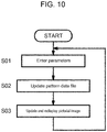
FIG. 10 is a flow diagram showing a procedure for updating and redisplaying the pictorial image as another example. - The following will describe a spinning-pattern setting apparatus of a spinning machine according to a first embodiment of the present invention with reference to the accompanying drawings. The embodiment disclosed herein is described by taking an example of a slub-pattern setting apparatus of a spinning machine, capable of setting a slub pattern corresponding to a spinning pattern (hereinafter referred to as merely a "slub-pattern setting apparatus").
- Referring to
FIG. 1 , a slub-pattern setting apparatus 10 includes acontrol device 11, aprogram memory 12, anoperation memory 13, aninput unit 14, aninput interface 15, anoutput interface 16, adisplay unit 17, and adata output unit 18. - The
control device 11 includes a CPU (not shown) that executes various programs. Thecontrol device 11 is connected to theprogram memory 12 and theoperation memory 13. Thecontrol device 11 is also connected to theinput unit 14 via theinput interface 15, and to thedisplay unit 17 via theoutput interface 16. Thecontrol device 11 serves as a pattern-data generation unit configured to generate slub-pattern data corresponding to spinning-pattern data. - The
program memory 12 is a ROM, i.e., a read-only memory, configured to store various programs and data to be used for executing the programs. The various programs include a slub-pattern-data generating program for generating the slub-pattern data from parameters of slub yarns, and a display program for thedisplay unit 17 displaying a pictorial image corresponding to pictorial data generated in a simulation based on the slub-pattern data. Thecontrol device 11 also serves as a pictorial-data generation unit configured to generate the pictorial data based on pattern data. In other words, thecontrol device 11 serves as a simulation unit configured to generate the pictorial image, corresponding to the pictorial data, in the simulation based on the slub-pattern data generated by the pattern-data generation unit. - The
operation memory 13 is a RAM, i.e., a random-access memory, configured to read out and rewrite data, and temporarily stores data entered via theinput unit 14 and results processed by thecontrol device 11. Specifically, theoperation memory 13 is configured to store the parameters of the slub yarns entered via theinput unit 14, the slub-pattern data generated by thecontrol device 11, and the data of the pictorial images of the slub yarns generated in the simulation based on the slub-pattern data. - The
input unit 14 serves as a parameter input unit, which is specifically a keyboard. An operator operates theinput unit 14 to enter the parameters of the slub yarns such as a pitch (mm), a length (mm), and a slub thickness (%). Theinput unit 14 is also used for entering various other data. The pitch refers to a length of an interval between any two adjacent slubs. The length refers to a length of the slub. The slub thickness refers to a thickness of the slub expressed as a percentage of the thickness of the slub to a reference thickness of the slub yarn, where the reference thickness of the slub yarn refers to a thickness of the pitch portion of the slub yarn, i.e., a thickness of the slub yarn at the interval between any two adjacent slubs. In other words, the slub thickness is set to exceed 100%. The data entered via theinput unit 14 is transferred to thecontrol device 11 via theinput interface 15. Theinput unit 14 may be a touch panel, instead of the keyboard, integrated with a display screen so as to have both a display function and an input function. - The
display unit 17, such as a liquid crystal display, is configured to display various data and the pictorial data. Thedisplay unit 17 is connected to thecontrol device 11 via theoutput interface 16. Referring toFIG. 2 , adisplay screen 19 of thedisplay unit 17 displays aparameter input window 20. Thedisplay screen 19 also displays the pictorial image such as aslub image window 21 and afabric image window 22.FIG. 2 shows only theparameter input window 20 and theslub image window 21, but not thefabric image window 22. Theslub image window 21 and thefabric image window 22 correspond to the pictorial images. - The
data output unit 18 is connected to thecontrol device 11 via theoutput interface 16. Thedata output unit 18 is an external storage medium such as a USB memory, used for retrieving data and programs from theoperation memory 13. - Referring to
FIGS. 2 and3 , theparameter input window 20 displayed in thedisplay screen 19 will now be described. Theparameter input window 20 serves as a parameter input panel, and is a window that displays the parameters of the slub yarns. The parameters are used for determining the slub pattern that is used by the spinning machine for spinning the slub yarn. Theparameter input window 20 displays the parameters entered via theinput unit 14. Referring toFIG. 3 , the slub pattern is determined by entering the parameters of the slub yarn, i.e., the pitch (mm), the length (mm), and the slub thickness (%), for each step for spinning the slub yarn. In the present embodiment, a maximum of thousand steps is available for the entry of the parameters that determine the slub patterns. The parameters entered and displayed in theparameter input window 20 are transferred to thecontrol device 11. Every time the parameters are entered, the parameters are transferred to thecontrol device 11, and thecontrol device 11 generates the slub-pattern data. - The
slub image window 21 corresponds to the pictorial image generated in the simulation based on the slub-pattern data generated from the entered parameters. Theslub image window 21 schematically shown inFIG. 2 displays a state of the slub yarn wound around a blackboard, which is generated in the simulation by thecontrol device 11 based on the slub-pattern data. In other words, theslub image window 21 displays the pictorial image of the slub yarn that is spun in the simulation. Referring toFIG. 4 , an illustrative example of theslub image window 21 is shown. In theslub image window 21 shown inFIG. 4 , white portions represent the slub yarn wound around the blackboard and black portions represent the blackboard seen through the wound slub yarn. In theslub image window 21, the slub yarn displayed as the white portions extends in the lengthwise direction and is arranged in the transverse direction to the lengthwise direction. For detailed settings of the pictorial image of the slub yarn displayed in theslub image window 21, a window for setting (not shown), i.e., a window other than theparameter input window 20, is used. - Another pictorial image of the data generated in the simulation is also displayed in the
fabric image window 22 shown inFIG. 5 , in addition to theslub image window 21 that displays the slub yarn generated in the simulation. Thefabric image window 22 displays the pictorial image of fabric woven by the slub yarn, which is generated in the simulation. Referring toFIG. 5 , an illustrative example of thefabric image window 22 is shown. Thefabric image window 22 displays weft yarns of the slub yarns generated in the simulation. In addition, thefabric image window 22 may display a fabric image corresponding to types of weaves such as a plain weave and a twill weave. In thefabric image window 22, the slub yarns extend in the lengthwise direction and the warp yarns extend in the transverse direction to the lengthwise direction. For detailed settings of the pictorial image of the fabric to be displayed in thefabric image window 22, a window for setting (not shown), i.e., a window other than theparameter input window 20, is used. - In the
display screen 19, either theslub image window 21 or thefabric image window 22 is displayed together with theparameter input window 20, by the display program. In the first embodiment described above, a first display state and a second display state are selectively switchable: the first display state includes theslub image window 21 together with theparameter input window 20, whereas the second display state includes thefabric image window 22 together with theparameter input window 20. - The slub-pattern data is determined by entering the parameters of the slub yarn for each step. The entered parameters are transferred to the
control device 11 serving as the pattern-data generation unit, and thecontrol device 11 generates the slub-pattern data from the entered parameters. The generated slub-pattern data is transferred to thecontrol device 11 serving as the simulation unit, and thecontrol device 11 generates slub image data or fabric image data generated in the simulation based on the slub-pattern data. Thedisplay unit 17 displays one of the pictorial images generated based on the slub image data and the fabric image data generated by thecontrol device 11. The pictorial images correspond to theslub image window 21 and thefabric image window 22. - Referring to
FIG. 6 , a procedure for updating and redisplaying theslub image window 21 and thefabric image window 22 is shown. A predetermined updating time elapses periodically in Step S01. Then, thecontrol device 11 outputs the slub-pattern data generated from the parameters entered at that point of time into a pattern data file to update the pattern data file in Step S02. The pattern data file is automatically updated every time the predetermined updating time elapses, without depending on an instruction by the operator. When any change is made in some of the parameters by the operator within the predetermined updating time, the slub-pattern data generated from the changed parameters is reflected on the pattern data file so that the pattern data file is updated. The predetermined updating time is set in the unit of seconds (e.g. 10 sec.). The predetermined updating time is enabled to be changed in a window for setting, i.e., a window other than theparameter input window 20. - The
control device 11 then generates the slub image data and the fabric image data generated in the simulation based on the pattern data file that is updated every time the predetermined updating time elapses, and updates and redisplays the pictorial image displayed in thedisplay screen 19 in Step S03. Specifically, theslub image window 21 and thefabric image window 22 displayed in thedisplay screen 19 are updated and redisplayed. In the embodiment described above, the pattern data file is periodically updated regardless of the presence or absence of any change in the parameters of the slub yarn. The pictorial image is updated and redisplayed by reflecting any change in the parameters if the change is made within the predetermined updating time, while no change is made in the pictorial image even if updating is performed when no change is made in the parameters within the predetermined updating time. - Operations of the slub-
pattern setting apparatus 10 will now be described. First, the operator activates the slub-pattern setting apparatus 10. The activation allows the slub-pattern setting apparatus 10 to display either theslub image window 21 or thefabric image window 22 in thedisplay screen 19 of thedisplay unit 17, in addition to theparameter input window 20. - The operator operates the slub-
pattern setting apparatus 10 to display theparameter input window 20 in thedisplay screen 19, and operates theinput unit 14 to enter the parameters used for determining the slub-pattern data. Specifically, entering the pitch (mm), the length (mm), and the slub thickness (%) is repeated in each step. The entered parameters are displayed in theparameter input window 20. - The slub-pattern data is output into the pattern data file, and the slub image data and the fabric image data are generated based on the pattern data file and shown as the pictorial images. The operator checks the
slub image window 21 and thefabric image window 22 displayed in thedisplay screen 19 to determine whether to fix the slub pattern. - In the embodiment described above, the slub-pattern data is automatically output into the pattern data file every time the predetermined updating time elapses even in the middle of the slub-pattern data being edited. The slub image data and the fabric image data are generated based on the generated pattern data file, and the pictorial images generated based on the slub image data and the fabric image data are updated and redisplayed. In other words, even in the middle of the slub-pattern data being edited by entering the parameters into the
parameter input window 20, theslub image window 21 and thefabric image window 22 are updated and redisplayed based on the slub-pattern data under being edited. - The operator checks the pictorial images in the
slub image window 21 and thefabric image window 22 in the middle of editing the slub-pattern data, and then fixes the final slub-pattern data. The slub-pattern data is allowed to be changed by changing some of the parameters even after the slub-pattern data is fixed. The operator downloads the fixed pattern data file from thedata output unit 18 into the external storage medium such as the USB memory, and then enters the fixed pattern data file into the spinning machine (not shown). The spinning machine spins the slub yarn based on the fixed slub-pattern data. - The following will describe the operational effects of the slub-
pattern setting apparatus 10 according to the first embodiment. - (1) The
control device 11 serving as the pattern-data generation unit generates the slub-pattern data from the parameters entered via theinput unit 14. Thecontrol device 11 serving as the simulation unit generates the pictorial images in the simulation based on the slub-pattern data. Thedisplay unit 17 displays one of the pictorial images generated by thecontrol device 11. Since the pictorial image displayed in thedisplay unit 17 is generated based on the slub-pattern data under editing and is automatically updated, the operator is enabled to check the pictorial images, even in the middle of editing, generated in the simulation based on the slub-pattern data under editing, and to identify how the pictorial images change by the change in the parameters in real time. This simplifies the parameter setting operation based on the pictorial image generated in the simulation and thus greatly reduces the time for the operation. - (2) The
control device 11 displays theparameter input window 20, which is used for entering the parameters of the slub yarn, together with the pictorial image in thedisplay unit 17. This enables the operator to concurrently compare the entered parameters with the pictorial image on the same screen, which allows the operator to easily identify how the pictorial image changes by the change in the parameters. - (3) The yarn to be spun is the slub yarn, and the spinning-pattern data is the slub-pattern data specified by the pitch, the length, and the slub thickness that are the parameters of the slub yarn. This enables the slub-pattern data to be generated from the parameters of the slub yarn such as the pitch, the length, and the slub thickness, the pictorial image generated in the simulation based on the slub-pattern data to be displayed, and also the
parameter input window 20 of the parameters of the slub yarn to be displayed. - (4) The pictorial image displayed in the
display unit 17 is automatically updated every time the predetermined updating time elapses. Since the pictorial image displayed in thedisplay unit 17 is automatically updated every time the predetermined updating time elapses, the operator is enabled to check the pictorial image generated based on the slub-pattern data that reflects any change in the parameters when some of the parameters are changed. - (5) The
slub image window 21 corresponding to the pictorial image shows the state of the slub yarn wound around the blackboard, which is generated in the simulation based on the slub-pattern data. Thefabric image window 22 displays the pictorial image of the fabric woven by the slub yarn, which is generated in the simulation based on the slub-pattern data. Theslub image window 21 and thefabric image window 22, generated based on the slub-pattern data under editing in the simulation, are enabled to be displayed. - (6) The pictorial image that reflects the slub-pattern data under editing is always allowed to be displayed, which enables the operator to check the pictorial image any time while editing the slub-pattern data.
- The following will describe a spinning-pattern setting apparatus of a spinning machine according to a second embodiment of the present invention with reference to the accompanying drawings. The second embodiment is different from the first embodiment in that distribution-graph pictorial data corresponding to the pictorial data is displayed in the display unit. In the description of the second embodiment, descriptions of components identical with those of the first embodiment described above will be omitted or simplified by providing the identical reference numerals as those of the first embodiment.
- Referring to
FIG. 7 , thedisplay screen 19 of thedisplay unit 17 of the second embodiment displays a distribution-graphpictorial data window 31 corresponding to the pictorial data, in addition to theparameter input window 20. It should be noted that thedisplay screen 19 is configured to display theslub image window 21 and thefabric image window 22, in addition to the distribution-graphpictorial data window 31, although these windows are not shown inFIG. 7 . - The distribution-graph
pictorial data window 31 is the pictorial data that visually shows a distribution of the slub patterns based on the slub-pattern data generated from the entered parameters. Referring toFIG. 8 , an illustrative example of the distribution-graphpictorial data window 31 is shown. The distribution-graphpictorial data window 31 shown inFIG. 8 includes arange input field 32, a distribution-graph display field 33, and a numericalvalue display field 34. Therange input field 32 is used for specifying ranges of the thickness (%) and length (mm), i.e., the parameters of the slub yarn. Therange input field 32 includesinput boxes range input field 32 also includesinput boxes range input field 32 also includes anOK button 32E used for fixing the entered ranges of thickness (%) and length (mm), and aFULL button 32F used for specifying the maximum ranges of thickness (%) and length (mm). - The distribution-graph display field 33 includes a length cell group in a horizontal axis, a thickness cell group in a vertical axis, and a number-of-yarns cell group of the rest of the cells arranged in a matrix. The length cell group includes a plurality of
length cells 33A. Each of thelength cells 33A shows the length (mm), i.e., the parameter of the slub yarn. The plurality of thelength cells 33A (ten cells) showing the length (mm) is arranged in the horizontal direction in the distribution-graph display field 33. Thelength cells 33A show values of the lengths (mm), i.e., the parameters of the slub yarn, within the range of the length (mm) specified in therange input field 32. The values shown in the plurality of thelength cells 33A increase in the order from left to right. - The thickness cell group includes a plurality of
thickness cells 33B. Each of thethickness cells 33B shows the thickness (%), i.e., the parameter of the slub yarn. The plurality of thethickness cells 33B (ten cells) showing the thickness (%) is arranged in the vertical direction in the distribution-graph display field 33. Thethickness cell 33B show values of the thicknesses (%), i.e., the parameters of the slub yarn, within the range of the thickness (%) specified in therange input field 32. The values shown in the plurality of thethickness cells 33B increase in the order from bottom to top. - The number-of-yarns cell group includes a plurality of number-of-
yarns cells 33C arranged in the matrix. The number of the number-of-yarns cells 33C of the number-of-yarns cell group is a hundred (10 x 10). Each of the number-of-yarns cells 33C shows the number of the slub yarns specified by the length (mm) in thecorresponding length cell 33A and the thickness (%) in thecorresponding thickness cell 33B. Lightness of the background of the number-of-yarns cell 33C gradually decreases as the value of the number of the slub yarns shown in the number-of-yarns cell 33C increases. - The numerical
value display field 34 is a table indicating the minimum value, the average value, and the maximum value of each of the thickness (%) and the length (mm) that are displayed in the distribution-graphpictorial data window 31. - The distribution-graph display field 33 of the second embodiment is a graph of distribution of the number of the slub yarns specified by the thicknesses (%) and the lengths (mm), in which the plurality of the number-of-
yarns cells 33C is arranged in the matrix with the plurality oflength cells 33A in the horizontal axis and the plurality ofthickness cells 33B in the vertical axis. - In the
display screen 19, the distribution-graphpictorial data window 31 is displayed together with theparameter input window 20, by the display program. In the second embodiment described above, the first display state, the second display state, and a third display state are selectively switchable: the first display state includes theslub image window 21 together with theparameter input window 20, the second display state includes thefabric image window 22 together with theparameter input window 20, and the third display state includes the distribution-graphpictorial data window 31 together with theparameter input window 20. - The
control device 11 generates the slub-pattern data from the parameters, and generates the distribution-graph pictorial data based on the slub-pattern data. Thedisplay unit 17 displays the distribution-graphpictorial data window 31 serving as the distribution-graph pictorial data corresponding to the pictorial data, generated by thecontrol device 11. - Referring to
FIG. 9 , a procedure for updating and redisplaying the distribution-graphpictorial data window 31 is shown. When the parameters of the slub yarn are entered in Step S11 while the slub-pattern data is being edited, then, thecontrol device 11 reflects the parameters entered at that point of time on the slub-pattern data, and outputs the slub-pattern data into the pattern data file to update the pattern data file in Step S12. In other words, when the parameters are entered, the pattern data file is automatically updated without depending on the instruction by the operator. When any change is made in the parameters by the operator, the slub-pattern data generated from the changed parameters is reflected on the pattern data file so that the pattern data file is updated. - Based on the pattern data file updated by reflecting the entered parameters, the
control device 11 updates the distribution-graphpictorial data window 31 that is displayed in thedisplay screen 19, in Step S13. In the second embodiment described above, the pattern data file is updated every time any of the parameters of the slub yarn is changed. In other words, the distribution-graphpictorial data window 31 is updated and redisplayed by reflecting any change in the parameters, whereas the distribution-graphpictorial data window 31 is not updated when no change is made in the parameters. - As to the distribution-graph
pictorial data window 31 displayed in thedisplay screen 19 of the second embodiment described above, when the distribution-graphpictorial data window 31 is updated by entering the parameters, updating is performed only on the cells, of the distribution-graph display field 33, affected by some change in the corresponding parameters, but not on the rest cells, of the distribution-graph display field 33, which are not affected by the change in the corresponding parameters. In this case, thecontrol device 11, upon any change in the parameters of the slub yarn, compares the slub-pattern data before and after the change, and updates only the cells, of the distribution-graph display field 33, affected by the difference in the slub-pattern data. Thecontrol device 11 does not update the distribution-graphpictorial data window 31, even if some change is made in the parameters of the slub yarn, unless the change causes the distribution-graph display field 33 to have some change that is identified by comparing the slub-pattern data before and after the change in the parameters. - In the second embodiment described above, the
control device 11 is configured to automatically generate the pattern data without depending on the instruction by the operator upon some change in the parameters. Every time the pattern data is generated, thecontrol device 11 generates and updates the distribution-graphpictorial data window 31 to be redisplayed in thedisplay unit 17. The operator is enabled to check the distribution-graphpictorial data window 31 generated based on the pattern data under editing, which allows the operator to identify how the distribution-graphpictorial data window 31 changes by the change in the parameters in real time. The operator is enabled to visually check the distribution of the slub yarns by checking the distribution-graphpictorial data window 31. The operator is enabled to intuitively recognize the difference between the number-of-yarns cells 33C showing large values and the number-of-yarns cells 33C showing small values by the difference in the lightness of the background of the number-of-yarns cell 33C. - In the second embodiment described above, the distribution-graph
pictorial data window 31 is updated and redisplayed by reflecting some change in the parameters, whereas the distribution-graphpictorial data window 31 is not updated when no change is made in the parameters. This reduces a load on the apparatus to be caused by updating and redisplaying the distribution-graphpictorial data window 31. As to the distribution-graphpictorial data window 31 displayed in thedisplay screen 19 of the second embodiment described above, updating is performed only on the part, of the distribution-graph display field 33, affected by some change in the corresponding parameters, but not on the rest part, of the distribution-graph display field 33, which are not affected by the change in the corresponding parameters. As a result, the distribution-graphpictorial data window 31 causes less flicker than a case where the entire distribution-graphpictorial data window 31 is updated even including the part, of the distribution-graphpictorial data window 31, not affected by the change in the parameters, which reduces a load on the operator's eyes. - In the second embodiment described above, the ranges of thickness (%) and length (mm) shown in the distribution-graph display field 33 are changeable by changing values to be entered in the
range input field 32 in the distribution-graphpictorial data window 31. - The scope of the present invention is not limited to the embodiments described above, but is intended to include any modifications equivalent in essence to the scope of the invention. For example, modifications as exemplified below may be made to the embodiments described above.
- In the first and second embodiments described above, the slub pattern corresponding to the spinning pattern is described as an example. However, the spinning pattern is not limited to the slub pattern. The spinning pattern is applicable to a color combination pattern of the yarn to be spun, instead of the slub pattern. In this case, parameters for determining the color combination pattern are different from the parameters of the slub yarn.
- In the first embodiment described above, the pictorial image displayed in the
display unit 17 is automatically updated in the predetermined cycles while the slub-pattern data is being edited. However, the scope of the present invention is not limited to the embodiment described above. For example, as shown inFIG. 10 , when some of the parameters of the slub yarn are entered while the slub-pattern data is being edited, the entered parameters may be reflected to update the pattern data file, and then the pictorial image may be updated based on the updated pattern data file and redisplayed. In this case, the pictorial image displayed in thedisplay unit 17 is updated and redisplayed every time some of the parameters are entered or changed, but is not updated without any entry or change in the parameters. This reduces a load on the apparatus to be caused by updating and redisplaying the pictorial image. Instead of updating and redisplaying the entire pictorial image at once, updating may be performed only on part of the distribution-graph pictorial data, as in the second embodiment described above, affected by some change in the parameters, but not on the rest of the distribution-graph pictorial data not affected by the change in the parameters. - In the first and second embodiments described above, the pictorial data that reflects the slub-pattern data under editing is always shown. However, the scope of the present invention is not limited to the embodiments described above. For example, the pictorial data may not be shown temporarily while the parameters are being entered, and may be shown after completion of the parameter entry. To be specific, this case may be applied when part or the entire of the pictorial data is hidden by overlapping with the
parameter input window 20 while the parameters are being entered. - In the first and second embodiments described above, the pattern data is output into the pattern data file. However, the scope of the present invention is not limited to the embodiments described above. The pattern data may be output in other method than the method of outputting the pattern data into the pattern data file. For example, the pattern data may be output via a socket communication such as a TCP/IP based communication.
- As to distribution-graph pictorial data of the second embodiment described above, when the distribution-graph pictorial data is updated by entering the parameters, updating of the distribution-graph pictorial data displayed in the
display unit 17 may be performed only on the part of the distribution-graph pictorial data affected by some change in the parameters, but not on the rest of the distribution-graph pictorial data not affected by the change in the parameters. However, the scope of the present invention is not limited to the embodiment described above. For example, when the distribution-graph pictorial data is updated by entering the parameters, the entire distribution-graph pictorial data may be updated including the part of the distribution-graph pictorial data not affected by some change in the parameters, not only the part of the distribution-graph pictorial data affected by the change in the parameters. - In the second embodiment described above, the distribution-graph pictorial data is updated and redisplayed every time any of the parameters are entered or changed while the slub-pattern data is being edited. However, the scope of the present invention is not limited to the embodiment described above. For example, the distribution-graph pictorial data in the
display unit 17 may be automatically updated and redisplayed in the predetermined cycles while the slub-pattern data is being edited. - A spinning-pattern setting apparatus (10) of a spinning machine that includes a parameter input unit (14) used for entering parameters of a yarn to be spun by the spinning machine, a pattern-data generation unit configured to generate pattern data from the parameters entered via the parameter input unit (14), a pictorial-data generation unit configured to generate pictorial data (21, 22, 31) based on the pattern data generated by the pattern-data generation unit, and a display unit (17) configured to display the pictorial data (21, 22, 31) generated by the pictorial-data generation unit. The pattern-data generation unit is configured to automatically generate the pattern data without depending on an instruction by an operator. The pictorial-data generation unit is configured to generate, every time the pattern data is generated, the pictorial data (21, 22, 31) so that the pictorial data (21, 22, 31) is updated and redisplayed in the display unit (17).
Claims (8)
- A spinning-pattern setting apparatus (10) of a spinning machine, comprising:a parameter input unit (14) used for entering a plurality of parameters of a yarn to be spun by the spinning machine;a pattern-data generation unit configured to generate pattern data from the parameters entered via the parameter input unit (14);a pictorial-data generation unit configured to generate pictorial data (21, 22, 31) based on the pattern data generated by the pattern-data generation unit; anda display unit (17) configured to display the pictorial data (21, 22, 31) generated by the pictorial-data generation unit, characterized in thatthe pattern-data generation unit is configured to automatically generate the pattern data without depending on an instruction by an operator, andthe pictorial-data generation unit is configured to generate, every time the pattern data is generated, the pictorial data (21, 22, 31) so that the pictorial data (21, 22, 31) is updated and redisplayed in the display unit (17).
- The spinning-pattern setting apparatus (10) of the spinning machine according to claim 1, characterized in that
the pictorial data (21, 22, 31) is a pictorial image (21, 22) generated in a simulation based on the pattern data. - The spinning-pattern setting apparatus (10) of the spinning machine according to claim 1, characterized in that
the pictorial data (21, 22, 31) is a distribution-graph pictorial data (31) generated based on the pattern data. - The spinning-pattern setting apparatus (10) of the spinning machine according to claim 1, characterized in that
the pattern-data generation unit is configured to control the display unit (17) to display a parameter input panel (20) together with the pictorial data (21, 22, 31). - The spinning-pattern setting apparatus (10) of the spinning machine according to any one of claims 1 to 3, characterized in that
the yarn to be spun is a slub yarn, and
the pattern data is slub-pattern data specified by the parameters of the slub yarn including a pitch, a length, and a slub thickness. - The spinning-pattern setting apparatus (10) of the spinning machine according to any one of claims 1 to 5, characterized in that
the display unit (17) is configured to display the pictorial data (21, 22, 31) that is automatically updated every time a predetermined updating time elapses. - The spinning-pattern setting apparatus (10) of the spinning machine according to any one of claims 1 to 5, characterized in that
the display unit (17) is configured to update and redisplay the pictorial data (21, 22, 31) when at least one of the parameters is changed. - The spinning-pattern setting apparatus (10) of the spinning machine according to any one of claims 1 to 7, characterized in that
the display unit (17) is configured to update and redisplay only part of the pictorial data (21, 22, 31) that is changed.
Applications Claiming Priority (2)
| Application Number | Priority Date | Filing Date | Title |
|---|---|---|---|
| JP2019220814 | 2019-12-06 | ||
| JP2020152763A JP7524688B2 (en) | 2019-12-06 | 2020-09-11 | Spinning pattern setting device for spinning machine |
Publications (2)
| Publication Number | Publication Date |
|---|---|
| EP3831990A1 true EP3831990A1 (en) | 2021-06-09 |
| EP3831990B1 EP3831990B1 (en) | 2022-09-28 |
Family
ID=73448833
Family Applications (1)
| Application Number | Title | Priority Date | Filing Date |
|---|---|---|---|
| EP20207382.1A Active EP3831990B1 (en) | 2019-12-06 | 2020-11-13 | Spinning-pattern setting apparatus for a spinning machine |
Country Status (2)
| Country | Link |
|---|---|
| EP (1) | EP3831990B1 (en) |
| CN (1) | CN112921458A (en) |
Citations (2)
| Publication number | Priority date | Publication date | Assignee | Title |
|---|---|---|---|---|
| EP2573236A2 (en) * | 2011-09-21 | 2013-03-27 | Murata Machinery, Ltd. | Textile machine and textile machine system |
| JP2013529728A (en) | 2010-06-30 | 2013-07-22 | マルゾーリ エス.ピー.エー. | Equipment for operating and programming the ring spinning machine |
Family Cites Families (6)
| Publication number | Priority date | Publication date | Assignee | Title |
|---|---|---|---|---|
| US5016183A (en) * | 1988-09-13 | 1991-05-14 | Computer Design, Inc. | Textile design system and method |
| JP2009276834A (en) * | 2008-05-12 | 2009-11-26 | Burein:Kk | Push-pull finishing simulation image generation method, system, program, and recording medium |
| DE102013208355A1 (en) * | 2013-05-07 | 2014-11-13 | Krones Ag | Apparatus and method for applying a label sleeve |
| US10600514B2 (en) * | 2016-05-27 | 2020-03-24 | Varian Medical Systems, Inc. | Intuitive automation in patient modeling |
| CN110147307B (en) * | 2019-05-15 | 2021-10-26 | 东华大学 | Embedded system simulation RAM, ROM result comparison system |
| CN110413346B (en) * | 2019-07-30 | 2022-09-20 | 中国工商银行股份有限公司 | Parameter updating method and device |
-
2020
- 2020-11-13 EP EP20207382.1A patent/EP3831990B1/en active Active
- 2020-12-02 CN CN202011388951.2A patent/CN112921458A/en active Pending
Patent Citations (2)
| Publication number | Priority date | Publication date | Assignee | Title |
|---|---|---|---|---|
| JP2013529728A (en) | 2010-06-30 | 2013-07-22 | マルゾーリ エス.ピー.エー. | Equipment for operating and programming the ring spinning machine |
| EP2573236A2 (en) * | 2011-09-21 | 2013-03-27 | Murata Machinery, Ltd. | Textile machine and textile machine system |
Also Published As
| Publication number | Publication date |
|---|---|
| CN112921458A (en) | 2021-06-08 |
| EP3831990B1 (en) | 2022-09-28 |
Similar Documents
| Publication | Publication Date | Title |
|---|---|---|
| US8312389B2 (en) | Visualization of decision logic | |
| US7363618B2 (en) | Software testing | |
| EP3831990B1 (en) | Spinning-pattern setting apparatus for a spinning machine | |
| Gloy et al. | Simulation and optimisation of warp tension in the weaving process | |
| JP7524688B2 (en) | Spinning pattern setting device for spinning machine | |
| BR102020023497B1 (en) | ROTATING MACHINE ROTARY PATTERN CONFIGURATION DEVICE | |
| US20240320385A1 (en) | Method and system for fabric design | |
| JP4921845B2 (en) | Opening pattern setting device in loom | |
| US6601019B1 (en) | System and method for validation of objects | |
| EP1876272A1 (en) | Pile-weaving-pattern editing device | |
| JP2000163259A (en) | Simulator and control logic construction tool | |
| CN113535314A (en) | Progress bar presenting method based on nodes | |
| JP3177235B2 (en) | Data output device | |
| CN117494021A (en) | Data processing methods, devices, storage media, terminals and products | |
| KR101540856B1 (en) | False dip tissue analysis and Display System of woven fabrics that use computer | |
| CN116193686B (en) | Indicator light control method and device, electronic equipment and storage medium | |
| KR101081733B1 (en) | Automatic teller machine which provides display composed of components | |
| US20240248595A1 (en) | Data analysis apparatus and data analysis method | |
| US7797632B2 (en) | Method for exposing graphical user interface layout logic and parameters | |
| Cocks et al. | Computer-aided simulation of production in the sewing room of a clothing factory | |
| CN121277749A (en) | CRC (cyclic redundancy check) checking method and device based on software mode, electronic equipment and storage medium | |
| JP2006520495A (en) | Method and apparatus for modifying modular structured messages | |
| CN117350999A (en) | White binding yarn breakage detection method, device, equipment and storage medium | |
| JPS63223824A (en) | Display screen position display device | |
| JPH07216682A (en) | Automatic weaving of high-accuracy colored pattern |
Legal Events
| Date | Code | Title | Description |
|---|---|---|---|
| PUAI | Public reference made under article 153(3) epc to a published international application that has entered the european phase |
Free format text: ORIGINAL CODE: 0009012 |
|
| STAA | Information on the status of an ep patent application or granted ep patent |
Free format text: STATUS: REQUEST FOR EXAMINATION WAS MADE |
|
| 17P | Request for examination filed |
Effective date: 20201113 |
|
| AK | Designated contracting states |
Kind code of ref document: A1 Designated state(s): AL AT BE BG CH CY CZ DE DK EE ES FI FR GB GR HR HU IE IS IT LI LT LU LV MC MK MT NL NO PL PT RO RS SE SI SK SM TR |
|
| GRAP | Despatch of communication of intention to grant a patent |
Free format text: ORIGINAL CODE: EPIDOSNIGR1 |
|
| STAA | Information on the status of an ep patent application or granted ep patent |
Free format text: STATUS: GRANT OF PATENT IS INTENDED |
|
| INTG | Intention to grant announced |
Effective date: 20220407 |
|
| GRAS | Grant fee paid |
Free format text: ORIGINAL CODE: EPIDOSNIGR3 |
|
| GRAA | (expected) grant |
Free format text: ORIGINAL CODE: 0009210 |
|
| STAA | Information on the status of an ep patent application or granted ep patent |
Free format text: STATUS: THE PATENT HAS BEEN GRANTED |
|
| AK | Designated contracting states |
Kind code of ref document: B1 Designated state(s): AL AT BE BG CH CY CZ DE DK EE ES FI FR GB GR HR HU IE IS IT LI LT LU LV MC MK MT NL NO PL PT RO RS SE SI SK SM TR |
|
| REG | Reference to a national code |
Ref country code: GB Ref legal event code: FG4D |
|
| REG | Reference to a national code |
Ref country code: CH Ref legal event code: EP |
|
| REG | Reference to a national code |
Ref country code: DE Ref legal event code: R096 Ref document number: 602020005347 Country of ref document: DE |
|
| REG | Reference to a national code |
Ref country code: AT Ref legal event code: REF Ref document number: 1521289 Country of ref document: AT Kind code of ref document: T Effective date: 20221015 |
|
| REG | Reference to a national code |
Ref country code: IE Ref legal event code: FG4D |
|
| REG | Reference to a national code |
Ref country code: LT Ref legal event code: MG9D |
|
| PG25 | Lapsed in a contracting state [announced via postgrant information from national office to epo] |
Ref country code: SE Free format text: LAPSE BECAUSE OF FAILURE TO SUBMIT A TRANSLATION OF THE DESCRIPTION OR TO PAY THE FEE WITHIN THE PRESCRIBED TIME-LIMIT Effective date: 20220928 Ref country code: RS Free format text: LAPSE BECAUSE OF FAILURE TO SUBMIT A TRANSLATION OF THE DESCRIPTION OR TO PAY THE FEE WITHIN THE PRESCRIBED TIME-LIMIT Effective date: 20220928 Ref country code: NO Free format text: LAPSE BECAUSE OF FAILURE TO SUBMIT A TRANSLATION OF THE DESCRIPTION OR TO PAY THE FEE WITHIN THE PRESCRIBED TIME-LIMIT Effective date: 20221228 Ref country code: LV Free format text: LAPSE BECAUSE OF FAILURE TO SUBMIT A TRANSLATION OF THE DESCRIPTION OR TO PAY THE FEE WITHIN THE PRESCRIBED TIME-LIMIT Effective date: 20220928 Ref country code: LT Free format text: LAPSE BECAUSE OF FAILURE TO SUBMIT A TRANSLATION OF THE DESCRIPTION OR TO PAY THE FEE WITHIN THE PRESCRIBED TIME-LIMIT Effective date: 20220928 Ref country code: FI Free format text: LAPSE BECAUSE OF FAILURE TO SUBMIT A TRANSLATION OF THE DESCRIPTION OR TO PAY THE FEE WITHIN THE PRESCRIBED TIME-LIMIT Effective date: 20220928 |
|
| REG | Reference to a national code |
Ref country code: NL Ref legal event code: MP Effective date: 20220928 |
|
| REG | Reference to a national code |
Ref country code: AT Ref legal event code: MK05 Ref document number: 1521289 Country of ref document: AT Kind code of ref document: T Effective date: 20220928 |
|
| PG25 | Lapsed in a contracting state [announced via postgrant information from national office to epo] |
Ref country code: HR Free format text: LAPSE BECAUSE OF FAILURE TO SUBMIT A TRANSLATION OF THE DESCRIPTION OR TO PAY THE FEE WITHIN THE PRESCRIBED TIME-LIMIT Effective date: 20220928 Ref country code: GR Free format text: LAPSE BECAUSE OF FAILURE TO SUBMIT A TRANSLATION OF THE DESCRIPTION OR TO PAY THE FEE WITHIN THE PRESCRIBED TIME-LIMIT Effective date: 20221229 |
|
| PG25 | Lapsed in a contracting state [announced via postgrant information from national office to epo] |
Ref country code: SM Free format text: LAPSE BECAUSE OF FAILURE TO SUBMIT A TRANSLATION OF THE DESCRIPTION OR TO PAY THE FEE WITHIN THE PRESCRIBED TIME-LIMIT Effective date: 20220928 Ref country code: RO Free format text: LAPSE BECAUSE OF FAILURE TO SUBMIT A TRANSLATION OF THE DESCRIPTION OR TO PAY THE FEE WITHIN THE PRESCRIBED TIME-LIMIT Effective date: 20220928 Ref country code: PT Free format text: LAPSE BECAUSE OF FAILURE TO SUBMIT A TRANSLATION OF THE DESCRIPTION OR TO PAY THE FEE WITHIN THE PRESCRIBED TIME-LIMIT Effective date: 20230130 Ref country code: ES Free format text: LAPSE BECAUSE OF FAILURE TO SUBMIT A TRANSLATION OF THE DESCRIPTION OR TO PAY THE FEE WITHIN THE PRESCRIBED TIME-LIMIT Effective date: 20220928 Ref country code: CZ Free format text: LAPSE BECAUSE OF FAILURE TO SUBMIT A TRANSLATION OF THE DESCRIPTION OR TO PAY THE FEE WITHIN THE PRESCRIBED TIME-LIMIT Effective date: 20220928 Ref country code: AT Free format text: LAPSE BECAUSE OF FAILURE TO SUBMIT A TRANSLATION OF THE DESCRIPTION OR TO PAY THE FEE WITHIN THE PRESCRIBED TIME-LIMIT Effective date: 20220928 |
|
| PG25 | Lapsed in a contracting state [announced via postgrant information from national office to epo] |
Ref country code: SK Free format text: LAPSE BECAUSE OF FAILURE TO SUBMIT A TRANSLATION OF THE DESCRIPTION OR TO PAY THE FEE WITHIN THE PRESCRIBED TIME-LIMIT Effective date: 20220928 Ref country code: PL Free format text: LAPSE BECAUSE OF FAILURE TO SUBMIT A TRANSLATION OF THE DESCRIPTION OR TO PAY THE FEE WITHIN THE PRESCRIBED TIME-LIMIT Effective date: 20220928 Ref country code: IS Free format text: LAPSE BECAUSE OF FAILURE TO SUBMIT A TRANSLATION OF THE DESCRIPTION OR TO PAY THE FEE WITHIN THE PRESCRIBED TIME-LIMIT Effective date: 20230128 Ref country code: EE Free format text: LAPSE BECAUSE OF FAILURE TO SUBMIT A TRANSLATION OF THE DESCRIPTION OR TO PAY THE FEE WITHIN THE PRESCRIBED TIME-LIMIT Effective date: 20220928 |
|
| P01 | Opt-out of the competence of the unified patent court (upc) registered |
Effective date: 20230519 |
|
| REG | Reference to a national code |
Ref country code: DE Ref legal event code: R097 Ref document number: 602020005347 Country of ref document: DE |
|
| PG25 | Lapsed in a contracting state [announced via postgrant information from national office to epo] |
Ref country code: NL Free format text: LAPSE BECAUSE OF FAILURE TO SUBMIT A TRANSLATION OF THE DESCRIPTION OR TO PAY THE FEE WITHIN THE PRESCRIBED TIME-LIMIT Effective date: 20220928 Ref country code: MC Free format text: LAPSE BECAUSE OF FAILURE TO SUBMIT A TRANSLATION OF THE DESCRIPTION OR TO PAY THE FEE WITHIN THE PRESCRIBED TIME-LIMIT Effective date: 20220928 Ref country code: AL Free format text: LAPSE BECAUSE OF FAILURE TO SUBMIT A TRANSLATION OF THE DESCRIPTION OR TO PAY THE FEE WITHIN THE PRESCRIBED TIME-LIMIT Effective date: 20220928 |
|
| REG | Reference to a national code |
Ref country code: BE Ref legal event code: MM Effective date: 20221130 |
|
| PG25 | Lapsed in a contracting state [announced via postgrant information from national office to epo] |
Ref country code: DK Free format text: LAPSE BECAUSE OF FAILURE TO SUBMIT A TRANSLATION OF THE DESCRIPTION OR TO PAY THE FEE WITHIN THE PRESCRIBED TIME-LIMIT Effective date: 20220928 |
|
| PLBE | No opposition filed within time limit |
Free format text: ORIGINAL CODE: 0009261 |
|
| STAA | Information on the status of an ep patent application or granted ep patent |
Free format text: STATUS: NO OPPOSITION FILED WITHIN TIME LIMIT |
|
| PG25 | Lapsed in a contracting state [announced via postgrant information from national office to epo] |
Ref country code: LU Free format text: LAPSE BECAUSE OF NON-PAYMENT OF DUE FEES Effective date: 20221113 |
|
| 26N | No opposition filed |
Effective date: 20230629 |
|
| PG25 | Lapsed in a contracting state [announced via postgrant information from national office to epo] |
Ref country code: IE Free format text: LAPSE BECAUSE OF NON-PAYMENT OF DUE FEES Effective date: 20221113 |
|
| PG25 | Lapsed in a contracting state [announced via postgrant information from national office to epo] |
Ref country code: SI Free format text: LAPSE BECAUSE OF FAILURE TO SUBMIT A TRANSLATION OF THE DESCRIPTION OR TO PAY THE FEE WITHIN THE PRESCRIBED TIME-LIMIT Effective date: 20220928 Ref country code: FR Free format text: LAPSE BECAUSE OF NON-PAYMENT OF DUE FEES Effective date: 20221128 Ref country code: BE Free format text: LAPSE BECAUSE OF NON-PAYMENT OF DUE FEES Effective date: 20221130 |
|
| PG25 | Lapsed in a contracting state [announced via postgrant information from national office to epo] |
Ref country code: CY Free format text: LAPSE BECAUSE OF FAILURE TO SUBMIT A TRANSLATION OF THE DESCRIPTION OR TO PAY THE FEE WITHIN THE PRESCRIBED TIME-LIMIT Effective date: 20220928 |
|
| PG25 | Lapsed in a contracting state [announced via postgrant information from national office to epo] |
Ref country code: MK Free format text: LAPSE BECAUSE OF FAILURE TO SUBMIT A TRANSLATION OF THE DESCRIPTION OR TO PAY THE FEE WITHIN THE PRESCRIBED TIME-LIMIT Effective date: 20220928 |
|
| PG25 | Lapsed in a contracting state [announced via postgrant information from national office to epo] |
Ref country code: HU Free format text: LAPSE BECAUSE OF FAILURE TO SUBMIT A TRANSLATION OF THE DESCRIPTION OR TO PAY THE FEE WITHIN THE PRESCRIBED TIME-LIMIT; INVALID AB INITIO Effective date: 20201113 Ref country code: BG Free format text: LAPSE BECAUSE OF FAILURE TO SUBMIT A TRANSLATION OF THE DESCRIPTION OR TO PAY THE FEE WITHIN THE PRESCRIBED TIME-LIMIT Effective date: 20220928 |
|
| PG25 | Lapsed in a contracting state [announced via postgrant information from national office to epo] |
Ref country code: MT Free format text: LAPSE BECAUSE OF FAILURE TO SUBMIT A TRANSLATION OF THE DESCRIPTION OR TO PAY THE FEE WITHIN THE PRESCRIBED TIME-LIMIT Effective date: 20220928 |
|
| GBPC | Gb: european patent ceased through non-payment of renewal fee |
Effective date: 20241113 |
|
| PG25 | Lapsed in a contracting state [announced via postgrant information from national office to epo] |
Ref country code: GB Free format text: LAPSE BECAUSE OF NON-PAYMENT OF DUE FEES Effective date: 20241113 |
|
| REG | Reference to a national code |
Ref country code: CH Ref legal event code: U11 Free format text: ST27 STATUS EVENT CODE: U-0-0-U10-U11 (AS PROVIDED BY THE NATIONAL OFFICE) Effective date: 20251201 |
|
| PG25 | Lapsed in a contracting state [announced via postgrant information from national office to epo] |
Ref country code: TR Free format text: LAPSE BECAUSE OF FAILURE TO SUBMIT A TRANSLATION OF THE DESCRIPTION OR TO PAY THE FEE WITHIN THE PRESCRIBED TIME-LIMIT Effective date: 20220928 |
|
| PGFP | Annual fee paid to national office [announced via postgrant information from national office to epo] |
Ref country code: DE Payment date: 20250930 Year of fee payment: 6 |
|
| PGFP | Annual fee paid to national office [announced via postgrant information from national office to epo] |
Ref country code: IT Payment date: 20251022 Year of fee payment: 6 |
|
| PGFP | Annual fee paid to national office [announced via postgrant information from national office to epo] |
Ref country code: CH Payment date: 20251201 Year of fee payment: 6 |