EP3831754A1 - Wire aligning and winding device, learning system used for same, and data collecting and accumulating system - Google Patents
Wire aligning and winding device, learning system used for same, and data collecting and accumulating system Download PDFInfo
- Publication number
- EP3831754A1 EP3831754A1 EP19844713.8A EP19844713A EP3831754A1 EP 3831754 A1 EP3831754 A1 EP 3831754A1 EP 19844713 A EP19844713 A EP 19844713A EP 3831754 A1 EP3831754 A1 EP 3831754A1
- Authority
- EP
- European Patent Office
- Prior art keywords
- wire rod
- winding
- data
- guide device
- correction device
- Prior art date
- Legal status (The legal status is an assumption and is not a legal conclusion. Google has not performed a legal analysis and makes no representation as to the accuracy of the status listed.)
- Granted
Links
Images

Classifications
-
- B—PERFORMING OPERATIONS; TRANSPORTING
- B65—CONVEYING; PACKING; STORING; HANDLING THIN OR FILAMENTARY MATERIAL
- B65H—HANDLING THIN OR FILAMENTARY MATERIAL, e.g. SHEETS, WEBS, CABLES
- B65H54/00—Winding, coiling, or depositing filamentary material
- B65H54/02—Winding and traversing material on to reels, bobbins, tubes, or like package cores or formers
- B65H54/28—Traversing devices; Package-shaping arrangements
- B65H54/2848—Arrangements for aligned winding
- B65H54/2854—Detection or control of aligned winding or reversal
-
- B—PERFORMING OPERATIONS; TRANSPORTING
- B21—MECHANICAL METAL-WORKING WITHOUT ESSENTIALLY REMOVING MATERIAL; PUNCHING METAL
- B21C—MANUFACTURE OF METAL SHEETS, WIRE, RODS, TUBES, PROFILES OR LIKE SEMI-MANUFACTURED PRODUCTS OTHERWISE THAN BY ROLLING; AUXILIARY OPERATIONS USED IN CONNECTION WITH METAL-WORKING WITHOUT ESSENTIALLY REMOVING MATERIAL
- B21C47/00—Winding-up, coiling or winding-off metal wire, metal band or other flexible metal material characterised by features relevant to metal processing only
- B21C47/02—Winding-up or coiling
- B21C47/04—Winding-up or coiling on or in reels or drums, without using a moving guide
-
- B—PERFORMING OPERATIONS; TRANSPORTING
- B21—MECHANICAL METAL-WORKING WITHOUT ESSENTIALLY REMOVING MATERIAL; PUNCHING METAL
- B21C—MANUFACTURE OF METAL SHEETS, WIRE, RODS, TUBES, PROFILES OR LIKE SEMI-MANUFACTURED PRODUCTS OTHERWISE THAN BY ROLLING; AUXILIARY OPERATIONS USED IN CONNECTION WITH METAL-WORKING WITHOUT ESSENTIALLY REMOVING MATERIAL
- B21C47/00—Winding-up, coiling or winding-off metal wire, metal band or other flexible metal material characterised by features relevant to metal processing only
- B21C47/34—Feeding or guiding devices not specially adapted to a particular type of apparatus
- B21C47/3408—Feeding or guiding devices not specially adapted to a particular type of apparatus for monitoring the lateral position of the material
- B21C47/3416—Feeding or guiding devices not specially adapted to a particular type of apparatus for monitoring the lateral position of the material with lateral edge contact
-
- B—PERFORMING OPERATIONS; TRANSPORTING
- B21—MECHANICAL METAL-WORKING WITHOUT ESSENTIALLY REMOVING MATERIAL; PUNCHING METAL
- B21C—MANUFACTURE OF METAL SHEETS, WIRE, RODS, TUBES, PROFILES OR LIKE SEMI-MANUFACTURED PRODUCTS OTHERWISE THAN BY ROLLING; AUXILIARY OPERATIONS USED IN CONNECTION WITH METAL-WORKING WITHOUT ESSENTIALLY REMOVING MATERIAL
- B21C47/00—Winding-up, coiling or winding-off metal wire, metal band or other flexible metal material characterised by features relevant to metal processing only
- B21C47/34—Feeding or guiding devices not specially adapted to a particular type of apparatus
- B21C47/345—Feeding or guiding devices not specially adapted to a particular type of apparatus for monitoring the tension or advance of the material
-
- B—PERFORMING OPERATIONS; TRANSPORTING
- B21—MECHANICAL METAL-WORKING WITHOUT ESSENTIALLY REMOVING MATERIAL; PUNCHING METAL
- B21C—MANUFACTURE OF METAL SHEETS, WIRE, RODS, TUBES, PROFILES OR LIKE SEMI-MANUFACTURED PRODUCTS OTHERWISE THAN BY ROLLING; AUXILIARY OPERATIONS USED IN CONNECTION WITH METAL-WORKING WITHOUT ESSENTIALLY REMOVING MATERIAL
- B21C47/00—Winding-up, coiling or winding-off metal wire, metal band or other flexible metal material characterised by features relevant to metal processing only
- B21C47/34—Feeding or guiding devices not specially adapted to a particular type of apparatus
- B21C47/3466—Feeding or guiding devices not specially adapted to a particular type of apparatus by using specific means
-
- B—PERFORMING OPERATIONS; TRANSPORTING
- B65—CONVEYING; PACKING; STORING; HANDLING THIN OR FILAMENTARY MATERIAL
- B65H—HANDLING THIN OR FILAMENTARY MATERIAL, e.g. SHEETS, WEBS, CABLES
- B65H54/00—Winding, coiling, or depositing filamentary material
- B65H54/02—Winding and traversing material on to reels, bobbins, tubes, or like package cores or formers
- B65H54/28—Traversing devices; Package-shaping arrangements
- B65H54/2848—Arrangements for aligned winding
- B65H54/2851—Arrangements for aligned winding by pressing the material being wound against the drum, flange or already wound material, e.g. by fingers or rollers; guides moved by the already wound material
-
- B—PERFORMING OPERATIONS; TRANSPORTING
- B65—CONVEYING; PACKING; STORING; HANDLING THIN OR FILAMENTARY MATERIAL
- B65H—HANDLING THIN OR FILAMENTARY MATERIAL, e.g. SHEETS, WEBS, CABLES
- B65H2701/00—Handled material; Storage means
- B65H2701/30—Handled filamentary material
- B65H2701/36—Wires
Definitions
- the present invention relates to a wire rod alignment winding apparatus and a learning system and a data collection storage system that are used for the wire rod alignment winding apparatus.
- a wire rod alignment winding apparatus for linearly winding a long wire rod, such as an electric cable or a communication cable, around a winding drum has been proposed (for example, refer to Patent Literature 1).
- a wire rod alignment winding apparatus causes a winding drum to rotate in a given direction and winds a wire rod to be wound using the winding drum while guiding the wire rod to the side of the winding drum using a guide unit.
- the guide unit causes the wire rod to shift horizontally in a lateral direction of the winding drum (direction of the center of rotation) in association with rotation of the winding drum and causes the wire rod to move vertically in a height direction of the winding drum for each winding layer of the wire rod on the winding drum.
- the wire rod alignment winding apparatus is able to wind the wire rod in alignment winding around the winding drum.
- the winding layer refers to a layer of the wire rod that is wound around the winding drum linearly.
- a force sensor detects a force based on displacement of a wire rod caused by a guide unit and, based on a signal of the force detection performed by the force sensor, a control unit automatically controls the upper, lower, right, and left positions of the guide unit.
- a control unit automatically controls the upper, lower, right, and left positions of the guide unit.
- linearly winding a wire rod around a winding drum is important from the point of view of smoothly drawing the wire rod from the winding drum in a step following the step of winding the wire rod, effectively utilization of a space in which the wire rod is wound around the winding drum, prevention of the wire rod from shifting from the winding drum during transfer, the exterior of the wire rod wound around the winding drum (tidiness of winding), etc.
- Patent Literature 1 Japanese Laid-open Patent Publication No. H10-236728
- the outer diameter of the wire rod and the width dimension of the winding drum (the interval between its brims on both sides in the width direction) varies and thus, in order to wind the wire rod in alignment winding around the winding drum, manual support of an operator to manually adjust the interval between the wire rods or between the wire rod and the brim using a jig is required when the wire rod is wound near the brim of the winding drum after the wire rod is wound linearly to the middle between the brims of the winding drum.
- the present invention was made in view of the above-described circumstances and an object of the present invention is to provide a wire rod winding apparatus that makes it possible to reduce manual support in an operation of winding a wire rod and easily wind the wire rod around a winding drum and a learning system and a data collection storage system that are used for the wire rod winding apparatus.
- a wire rod alignment winding apparatus that winds a wire rod around a winding drum, includes: a data collection storage system that collects at least data representing manual operations on a guide device and a correction device, the guide device guiding the wire rod to the winding drum, the correction device correcting a position in which the wire rod is wound around the winding drum, data representing each condition of each of the wire rod, the guide device, and the correction device, and data representing success or failure of targeted alignment winding of the wire rod and stores the collected sets of data in association with success or failure of the targeted alignment winding of the wire rod as wire rod winding operation data; and a learning device that, based on the stored wire rod winding operation data, learns manual operations on the guide device and the correction device in at least one of success and failure in the targeted alignment winding of the wire rod and constructs a control law which allows automatic control on the guide device and the correction device such that the wire rod is wound around the winding drum in the targeted alignment winding.
- the data collection storage system further collects data representing each set of automatic control on the guide device and the correction device, takes the further data into consideration, and updates the wire rod winding operation data, and the learning device learns, based on the updated wire rod winding operation data, each set of automatic control on the guide device and the correction device in at least any one of success and failure of the targeted alignment winding of the wire rod and updates the control law.
- the above wire rod alignment winding apparatus further includes a success/failure determination unit that determines success or failure of the targeted alignment winding of the wire rod based on the data representing each condition.
- the above wire rod alignment winding apparatus further includes an alarm unit that outputs an alarm when the success/failure determination unit determines that the targeted alignment winding of the wire rod fails.
- a wire rod alignment winding apparatus that winds a wire rod around a winding drum, includes: a data collection storage system that collects at least data representing manual operations on a guide device and a correction device, the guide device guiding the wire rod to the winding drum, the correction device correcting a position in which the wire rod is wound around the winding drum, data representing each condition of each of the wire rod, the guide device, and the correction device, and data representing success or failure of targeted alignment winding of the wire rod and stores the collected sets of data in association with success or failure of the targeted alignment winding of the wire rod as wire rod winding operation data; and a learning device that has a control law that is constructed previously in order to automatically control the guide device and the correction device and, based on the wire rod winding operation data that is stored in the data collection storage system, learns manual operations on the guide device and the correction device in at least any one of success and failure of the targeted alignment winding of the wire rod, and updates the control law so that the wire rod is wound around the winding drum
- a learning system that is used for a wire rod alignment winding apparatus that winds a wire rod around a winding drum, includes: a data collection storage system that collects at least data representing manual operations on a guide device and a correction device, the guide device guiding the wire rod to the winding drum, the correction device correcting a position in which the wire rod is wound around the winding drum, data representing each condition of each of the wire rod, the guide device, and the correction device, and data representing success or failure of targeted alignment winding of the wire rod and stores the collected sets of data in association with success or failure of the targeted alignment winding of the wire rod as wire rod winding operation data; and a learning device that, based on the stored wire rod winding operation data, learns manual operations on the guide device and the correction device in at least one of success and failure in the targeted alignment winding of the wire rod and constructs a control law which allows automatic control on the guide device and the correction device such that the wire rod is wound around the winding drum in the targeted alignment winding.
- a data collection storage system includes: a data collection device that collects at least data representing manual operations on a guide device and a correction device, the guide device guiding a wire rod to a winding drum of a wire rod alignment winding apparatus that winds the wire rod around the wiring drum, the correction device correcting a position in which the wire rod is wound around the winding drum, data representing conditions of the wire rod, the guide device, and the correction device, and data representing success or failure of targeted alignment winding of the wire rod. Further, the data are stored in association with success or failure of the targeted alignment winding of the wire rod.
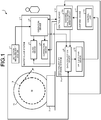
- FIG. 1 is a diagram illustrating an example of the configuration of the wire rod alignment winding apparatus according to the embodiment of the present invention.
- a wire rod alignment winding apparatus 1 includes a wire rod winding device 2, a master/slave system 3, a detection measurement system 7, a data collection storage system 8, a learning device 11, and a control device 12.
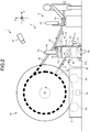
- FIG. 2 is a diagram illustrating an example of a configuration of the wire rod winding device, the master/slave system, and the detection measurement system according to the embodiment.
- FIG. 2 illustrates the wire rod winding device 2, the master/slave system 3, and the detection measurement system 7 that are viewed from the direction of the width of a winding drum 15.
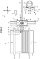
- FIG. 3 is a top view of the wire rod winding device, the master/slave system, and the detection measurement system that are illustrated in FIG. 2 .
- directions of an X-axis, a Y-axis and a Z-axis of a three-axis orthogonal coordinate system are set.
- the direction of the depth of the winding drum 15 corresponds to an X-axis direction.
- the direction of the width of the winding drum 15 corresponds to a Y-axis direction.
- the direction orthogonal to the width direction of the winding drum 15 is a direction orthogonal to the width direction of the winding drum 15 viewed from the depth direction (X-axis direction) of the winding drum 15 and corresponds to the Z-axis direction.
- the Z-axis direction is a vertical direction and the Y-axis direction is the horizontal direction.
- the width direction of the winding drum 15 is also referred to as a lateral direction of the winding drum 15.
- the direction orthogonal to the width direction of the winding drum 15 is also referred to a direction of the height of the winding drum 15 (top-down direction).
- the wire rod winding device 2 is a device for winding a wire rod 16 to be wound around the winding drum 15.
- the wire rod winding apparatus 2 includes a winding driver 2a that supports the winding drum 15 such that the winding drum 15 is rotatable.
- the winding drum 15 includes brims 15a and 15b on both sides of a drum body 15c in a direction of the width of the drum body 15c. As illustrated in FIGS.
- the wire rod winding device 2 rotates the winding drum 15 using the mechanism of the winding driver 2a with the Y-axis direction serving as the direction of the center of rotation of the winding drum 15 and winds the wire rod 16 between both the brims 15a and 15b of the winding drum 15.
- a long wire rod such as an electric cable or a communication cable, is considered.
- the master/slave system 3 includes a guide device 4, a correction device 5, and an operation device 6.
- the master/slave system 3 is a system for manually controlling the guide device 4 and the correction device 5 based on manual operations of the operator on the operation device 6.
- the guide device 4 shifts the wire rod 16 in the width direction of the winding drum 15 (the Y-axis direction) and the direction orthogonal to the width direction (x-axis direction) and guides the wire rod 16 between the brims 15a and 15b of the winding drum 15.
- the guide device 4 includes a width-direction guide 41 and a vertical-direction guide 42.
- the width-direction guide 41 includes a width-direction driver 41a for a shift along rails 45 that are laid such that the Y-axis direction corresponds to a longitudinal direction and a traverse roller pair 43 formed of a pair of guide rollers arrayed in the Y-axis direction.
- the traverse roller pair 43 is arranged rotatably on a device upper surface of the guide device 4 (specifically, the device upper surface of the vertical-direction guide 42).
- the traverse roller pair 43 is configured to rotate in association with delivery of the wire rod 16 to the winding drum 15 while sandwiching the wire rod 16 on a path line toward the winding drum 15 in the Y-axis direction.
- the width-direction guide 41 is configured to guide the wire rod 16 with respect to the Y-axis direction to the space between both the brims 15a and 15b of the winding drum 15 using the mechanism of the width-direction driver 41a and the traverse roller pair 43.
- the vertical-direction guide 42 includes a vertical-direction driver 42a for a shift in the Z-axis direction and a support roller 44 formed of a guide roller that supports the wire rod 16 while rotating.
- the support roller 44 is arranged rotatably on the device upper surface of the vertical-direction guide 42 in a mode where the Y-axis direction corresponds to the longitudinal direction.
- the support roller 44 is configured to rotate in association with delivery of the wire rod 16 to the winding drum 15 while supporting the wire rod 16 on the path line toward the winding drum 15 such that the wire rod 16 is lifted up from the bottom.
- the vertical-direction guide 42 is configured to, using the mechanism of the vertical-direction driver 42a and the support roller 44, guide the wire rod 16 with respect to the Z-axis direction to the space between both the brims 15a and 15b of the winding drum 15.
- the correction device 5 is a device for correcting the position in which the wire rod 16 is wound around the winding drum 15.
- the correction device 5 includes a hitting arm 51 including a hitting part 52 at the tip of the hitting arm 51 and an arm driver 53 and is arranged in the guide device 4.
- the hitting arm 51 extends from the side of the guide device 4 to the side of the winding drum 15 on the wire rod winding device 2 and is configured to be rotatable about the Y-axis direction corresponding to a center of rotation and reciprocate in the Y-axis direction and the longitudinal direction of the hitting arm 51.
- the arm driver 53 is configured to enable the hitting arm 51 to rotate and reciprocate.
- the correction device 5 is configured to hit the wire rod 16 with the hitting part 52 in order to correct the position in which the wire rod 16 is wound around the winding drum 15 using the mechanism of the hitting arm 51 and the arm driver 53.
- the operation device 6 is a device for manually operating the guide device 4 and the correction device 5.
- the operation device 6 includes an operation lever 61, a display unit 62, an input unit 63, a start button 64, a stop button 65, an interruption button 66, a mode switch 67, and an alarm 68.
- the operation lever 61 is used by the operator to manually operate the guide device 4 and the correction device 5.
- the display unit 62 displays various types of information necessary to manually operate the guide device 4 and the correction device 5.
- information to be displayed on the display unit 62 for example, information, such as the winding condition of the wire rod 16 that is wound around the winding drum 15, is included.
- the input unit 63 is for inputting various types of information to the control device 12 according to input operations of the operator.
- information that is input by the input unit 63 for example, the distance between both the brims 15a and 15b of the winding drum 15 and product information, such as the outer diameter and density of the wire rod 16, is included.
- the start button 64 is operated to start automatic control on the guide device 4 and the correction device 5 using the control device 12.
- the stop button 65 is operated to stop the automatic control on the guide device 4 and the correction device 5 using the control device 12.
- the interruption button 66 is operated to interrupt (urgently stop) the automatic control on the guide device 4 and the correction device 5 using the control device 12.
- the mode switch 67 is operated to switch the mode of control on the guide device 4 and the correction device 5 to manual control using the operation device 6 or automatic control using the control device 12.
- the alarm 68 outputs an alarm to notify the operator of occurrence of a trouble in winding the wire rod 16 around the winding drum 15.
- the detection measurement system 7 detects or measures the condition of the wire rod 16, the condition of the guide device 4, and the condition of the correction device 5.
- the detection measurement system 7 is formed of encoders 71 and 72 for detecting or measuring the condition of the guide device 4; ranging units 77 and 78 and an encoder 80 for detecting or measuring the condition of the correction device 5; counters 73, 74, and 75, ranging units 76 and 79, and imaging devices 81 and 82 for detecting or measuring the condition of the wire rod 16.
- condition of the wire rod 16 for example, a physical quantity representing the winding condition of the wire rod 16 around the winding drum 15, a tension of the wire rod 16 toward the winding drum 15, and a physical quantity representing a position of the path line are considered.
- condition of the guide device 4 physical quantities representing the conditions of the traverse roller pair 43 and the support roller 44 are considered.
- condition of the correction device 5 a physical quantity representing a positional relationship between the wire rod 16 and the hitting arm 51 is considered.
- the data collection storage system 8 is an example of a data collection storage system according to the present invention.
- the data collection storage system 8 is a system that collects and store data necessary for a learning process that is performed by the learning device 11.
- the data collection storage system 8 is formed of a data collection device 9 and a data storage device 10.
- the data collection device 9 includes a processor that performs operations necessary for a data determination process, etc., a memory that stores a program and data for performing the operations, and an input/output interface for transmitting and receiving data and signals.
- the data collection device 9 collects at least data representing each manual operation performed on the guide device 4 and the correction device 5 using the operation device 6, data representing each of the above-described conditions (the respective conditions of the wire rod 16, the guide device 4, and the correction device 5) that are detected or measured by the detection measurement system 7, and data representing success or failure of targeted alignment winding of the wire rod 16.
- the collected data are stored in association with success or failure of targeted alignment winding of the wire rod 16.
- the data collection device 9 associates sets of collected data with success or failure of targeted alignment winding of the wire rod 16, for example, in chronological order.
- the data storage device 10 includes a memory that stores data such that the data can be updated and an input/output interface for transmitting and receiving data and signals. As described above, the data storage device 10 stores data that is processed by the data collection device 9 as wire rod winding operation data.
- the learning device 11 performs machine learning, such as reinforcement learning or the like, in order to construct a control law for the control device 12 to control the guide device 4 and the correction device 5.
- the learning device 11 includes a processor that performs operations necessary for machine learning, a memory that stores a program and data for performing the operations, and an input/output interface for transmitting and receiving data and signals.
- the learning device 11 learns each manual operation on the guide device 4 and the correction device 5 in at least one of success and failure of targeted alignment winding of the wire rod 16 (in the embodiment, both success and failure of targeted alignment winding) based on wire rod winding operation data that is stored by the data storage device 10. Accordingly, the learning device 11 constructs a control law 11a according to which the guide device 4 and the correction device 5 are controllable such that the wire rod 16 is wound in targeted alignment winding between both the brims 15a and 15b of the winding drum 15.
- the control device 12 automatically controls the guide device 4 and the correction device 5.
- the control device 12 includes a success/failure determination unit 12a.
- the success/failure determination unit 12a determines whether targeted alignment winding of the wire rod 16 succeeds or fails based on data representing each of the above-described conditions that are detected or measured by the detection measurement system 7.
- the control device 12 is configured to be able to automatically determine whether targeted alignment winding succeeds or fails using the success/failure determination unit 12a based on the data that is acquired from the detection measurement system 7.
- the detection measurement system 7, the data collection storage system 8, and the learning device 11 form a learning system that is used for the wire rod alignment winding apparatus 1 including the wire rod winding device 2, the master/slave system 3 (the guide device 4, the correction device 5, and the operation device 6) and the control device 12.
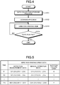
- FIG. 4 is a flowchart illustrating an example of the wire rod alignment winding method according to the embodiment of the present invention.
- the wire rod alignment winding apparatus 1 winds the wire rod 16 around the winding drum 15 based on manual operations performed by the operator using the operation device 6 or automatic control performed by the control device 12 according to the control law 11a.
- the wire rod alignment winding apparatus 1 performs a data collection storage process of collecting and storing historic data on winding the wire rod 16 around the winding drum 15 by manual operations on the guide device 4 and the correction device 5 (step S101).
- the collected historic data are stored as wire rod winding operation data in the data collection storage system 8.
- the wire rod alignment winding apparatus 1 Based on the stored wire rod winding operation data, the wire rod alignment winding apparatus 1 performs a learning process of learning each manual operation on the guide device 4 and the correction device 5 performed when the wire rod 16 is wound around the winding drum 15 and constructing the control laws 11a for linearly winding the wire rod 16 around the winding drum 15 (step S102). In the wire rod alignment winding apparatus 1, the learning process is performed by the learning device 11.
- the wire rod alignment winding apparatus 1 performs a wire rod winding operation of automatically controlling the guide device 4 and the correction device 5 according to the constructed control law 11a to wind the wire rod 16 around the winding drum 15 (step S103).
- Automatic control on the guide device 4 and the correction device 5 is performed by the control device 12.
- manual operation on the guide device 4 and the correction device 5 are performed as required using the operation device 6.
- the wire rod alignment winding apparatus 1 does not end the wire rod winding operation (NO at step S104), returns to step S103, and repeats the process at and after step S103.
- the wire rod alignment winding apparatus 1 ends the wire rod winding operation (YES at step S104) and ends the process.
- step S101 The aforementioned data collection storage process at step S101 will be described in detail.
- historic data obtained when the operator manually operates the guide device 4 and the correction device 5 using the operation device 6 and thus winds the wire rod 16 around the winding drum 15 is collected and is stored as wire rod winding operation data.
- the collected historic data for example,
- the detection measurement system 7 detests or measures the condition of the guide device 4, the condition of the correction device 5, and the condition of the wire rod 16.
- the position of the traverse roller pair 43 in the Y-axis direction and the position of the support roller 44 in the Z-axis direction are taken.
- the position of the traverse roller pair 43 in the Y-axis direction is detected by the encoder 71 that is arranged in the width-direction driver 41a of the width-direction guide 41 that shifts integrally with the traverse roller pair 43 in the Y-axis direction.
- the position of the support roller 44 in the Z-axis direction is detected by the encoder 72 that is arranged in the vertical direction driver 42a of the vertical-direction guide 42 that shifts integrally with the support roller 44 in the Z-axis direction.
- the condition of the correction device 5 for example, physical quantities representing a positional relationship between the hitting arm 51 and the wire rod 16, physical quantities representing positional relationships between the hitting arm 51 and the brims 15a and 15b of the winding drum 15, a position of rotation of the hitting arm 51, and a position of the hitting arm 51 in the longitudinal direction are considered.
- the physical quantities representing the positional relationship between the hitting arm 51 and the wire rod 16 are measured by the ranging unit 77 that is arranged in the hitting part 52 of the hitting arm 51.
- the ranging unit 77 measures, as the physical quantities, distances each between the hitting part 52 and the wire rod 16 in the X-axis direction and the Y-axis direction.
- the physical quantities representing positional relationships each between the hitting arm 51 and each of the brims 15a and 15b are measured by the ranging unit 78 that is arranged in the hitting arm 51.
- the ranging unit 78 measures, as the physical quantities, the distances from the hitting arm 51 to the brims 15a and 15b in the Y-axis direction.
- the position of rotation and the longitudinal direction position of the hitting arm 51 are detected by the encoder 80 that is arranged in the arm driver 53 of the correction device 5.
- the condition of the wire rod 16 for example, a rate at which the wire rod 16 toward the winding drum 15 is sent (linear velocity), the number of winds of the wire rod 16 around the winding drum 15 and the number of layers of the wound wire rod 16, physical quantities representing positional relationships between the brims 15a and 15b of the winding drum 15 and the wire rod 16, a physical quantity representing a tension of the wire rod 16, the exterior of the wire rod 16 wound around the winding drum 15, and clearance between the wire rods 16 wound around the winding drum 15 are considered.
- the linear velocity of the wire rod 16 is measured by the counter 73 that is arranged in the traverse roller pair 43.
- the counter 73 counts the number of rotations of the traverse roller pair 43 associated with delivery of the wire rod 16 and measure the linear velocity of the wire rod 16 through the count of the number of rotations.
- the number of winds of the wire rod 16 around the winding drum 15 is measured by the counter 74 that is arranged in the wire rod winding device 2.
- the counter 74 measures the number of rotations of the winding drum 15 and, through the count of the number of rotations, measures the number of winds of the wire rod 16 using a wind of the wire rod 16 caused by one rotation of the winding drum 15 as a unit (one wind).
- the number of layers of the wire rod 16 wound around the winding drum 15 is the number of layers of the wire rod 16 that is wound around the drum body 15c between both the brims 15a and 15b of the winding drum 15 in alignment winding and the number of layers is measured by the counter 75.
- the counter 75 counts the number of times the guide device 4 replicates to the positive side or the negative side in the Y-axis direction between both the brims 15a and 15b of the winding drum 15 and, through the count of the number of times, measures the number of layers of the wound wire rod 16.
- the physical quantities representing the positional relationships between the brims 15a and 15b of the winding drum 15 and the wire rod 16 are measured by the ranging unit 76.
- the ranging unit 76 measures, as the physical quantities, distances from the path line of the wire rod 16 that is delivered from the side of the guide device 4 to the side of the winding drum 15 to the brims 15a and 15b in the Y-axis direction.
- the physical quantity representing the tension of the wire rod 16 is measured by the ranging unit 79 that is arranged on the device upper surface of the guide device 4 (in the embodiment, the device upper surface of the vertical-direction guide 42 in the embodiment).
- the ranging unit 79 measures, as the physical quantity, the distance from the device upper surface of the vertical-direction guide 42 to the wire rod 16.
- the tension of the wire rod 16 increases in association with an increase in the distance from the device upper surface to the wire rod 16.
- the exterior of the wire rod 16 wound around the winding drum 15 is detected as an image by the imaging device 81.
- the imaging device 81 is arranged on an upper side such that the drum body 15c (a part around which the wire rod 16 is wound) between both the brims 15a and 15b of the winding drum 15 is captured within the field of view.
- the imaging device 81 captures an image representing the exterior of the wire rod 16 wound around the winding drum 15.
- the clearance between the wire rods 16 wound around the winding drum 15 is detected by the imaging device 82 that is arranged near the hitting arm 51 of the correction device 5.
- the imaging device 82 captures an image of the wire rod 16 that is wound around the winding drum 15 and performs given image processing on the acquired image, thereby detecting the clearance between the wire rods 16.
- Table 1 A list of sets of detection measurement data (physical quantities and images) in the embodiment is exemplified in Table 1 below.
- Table 1 Condition of guide device Position of traverse roller pair in Y-axis direction Position of support roller in Z-axis direction Condition of correction device Physical quantities representing positional relationships between hitting arm and wire rod (Each of distances from hitting part to wire rod in X-axis direction and Y-axis direction) Physical quantities representing positional relationships between hitting arm and brims of winding drum (Distances from hitting arm to brims in Y-axis direction) Position of rotation of hitting arm and position of hitting arm in longitudinal direction Condition of wire rod Linear velocity of wire rod Number of winds of wire rod Number of layers of wound wire rod Physical quantities representing positional relationships between brims of winding drum and wire rod (Distances from path line of wire rod to brims) Physical quantity representing tension of wire rod (Distance from device upper surface of vertical direction guide unit to wire rod) Exterior of wound wire rod (Image representing exterior of wind) Clearance between
- the physical quantity representing the positional relationship between the hitting arm 51 and the wire rod 16 the physical quantities representing the positional relationships between the hitting arm 51 and the brims 15a and 15b of the winding drum 15, the position of rotation of the hitting arm 51 and the position of the hitting arm 51 in the longitudinal, and the clearance between the wire rods 16 wound around the winding drum 15 are information useful to appropriately hit the wire rod 16 using the hitting part 52 of the correction device 5 in order to correct the position in which the wire rod 16 is wound around the winding drum 15.
- the position of the traverse roller pair 43 in the Y-axis direction, the position of the support roller 44 in the Z-axis direction, the linear velocity of the wire rod 16, the number of winds, and the number of layers of winds are information useful to appropriately shift (guide) the wire rod 16 to be wound around the winding drum 15 in the Y-axis direction and the Z-axis direction, using the guide device 4.
- the physical quantities representing the positional relationships between the brims 15a and 15b of the winding drum 15 and the wire rod 16 are information that is useful to sense that the guide device 4 replicates to the positive side or the negative side in the Y-axis direction between both the brims 15a and 15b of the winding drum 15.
- the physical quantity representing the tension of the wire rod 16 is information useful to sense that the wire rod 16 inappropriately overlays the wire rod 16 on the winding drum 15.
- the exterior of the wire rod 16 wound around the winding drum 15 is information useful to determine whether targeted alignment winding of the wire rod 16 wound around the winding drum 15 succeeds or fails.
- the physical quantity representing the positional relationship between the hitting arm 51 and the wire rod 16 the physical quantities representing the positional relationships between the hitting arm 51 and the brims 15a and 15b of the winding drum 15, the position of the traverse roller pair 43 in the Y-axis direction, the position of the support roller 44 in the Z-axis direction, the clearance between the wire rods 16 wound around the winding drum 15, and the exterior of the wire rod 16 wound around the winding drum 15 are important to determine, in order to wind the wire rod 16 around the winding drum 15 in targeted alignment winding, which part of the wire rod 16 should be hit to correct the winding position, in which of the Y-axis direction and the Z-axis direction the path line of the wire rod 16 guided to the winding drum 15, and into what condition the winding condition of the wire rod 16 turns because of correction of the position in which the wire rod 16 is wound and a shift of the path line.
- each operation signal that is transmitted from the operation device 6 to each of the guide device 4 and the correction device 5 according to operations of the operator on the operation lever 61, etc. is taken.
- Operation signals to the guide device 4 includes an operation signal to the width-direction guide 41 and an operation signal to the vertical-direction guide 42.
- the operation signal to the width-direction guide 41 serves as data representing whether a manual operation to shift the width-direction guide 41 to any position in the Y-axis direction has been performed.
- the operation signal to the width-direction guide 41 serves as data representing whether a manual operation to shift the vertical-direction guide 42 to any position of the Z-axis direction has been performed.
- the operation signal to the correction device 5 serves as data representing whether a manual operation to shift the hitting part 52 of the hitting arm 51 to any position in the three-axis orthogonal coordinate system of the Z-axis, Y-axis and Z-axis has been performed.
- Table 2 Data representing manual operation on guide device Operation signal to guide device (Operation signal to width direction guide unit and operation signal to vertical direction guide unit) Data representing manual operation on correction device Operation signal to correction device
- a stop signal that is output from the operation device 6 according to an operation of the operator on the stop button 65 and an interruption signal that is output from the operation device 6 according to an operation of the operator on the interruption button 66 are taken.
- the stop button 65 is operated to stop the wire rod alignment winding apparatus 1 when winding the wire rod 16 around the winding drum 15 in targeted alignment winding completes.
- a stop signal corresponding to such an operation on the stop button 65 serves as data representing that targeted alignment winding of the wire rod 16 around the winding drum 15 has succeeded.
- the interruption button 66 is operated to interrupt the wire rod alignment winding apparatus 1 when the wire rod 16 is not wound around the winding drum 15 in targeted alignment winding.
- An interruption signal corresponding to such an operation on the interruption button 66 serves as data representing that targeted alignment winding of the wire rod 16 around the winding drum 15 does not succeed (failure in targeted alignment winding).
- Table 3 Data representing success or failure of targeted alignment winding of wire rod Stop signal (Data representing success of targeted alignment winding) Interruption signal (Data representing failure of targeted alignment winding)
- success/failure data obtained by the success/failure determination unit 12a by automatically determining whether alignment winding has succeeded or failed can be employed in addition to the data that is exemplified in FIG. 3 .
- the success failure determination unit 12a determines whether alignment winding of the wire rod 16 has succeeded or failed in every given period based on whether the above-described interruption signal is input. Accordingly, it is possible to classify, with respect to each given period, the above-described wire rod winding operation data into data on the case where alignment winding of the wire rod 16 succeeds or data on the case where alignment winding of the wire rod 16 fails.
- data on each period without input of any interruption signal to the success/failure determination unit 12a can be classified into data representing success of targeted alignment winding of the wire rod 16.
- Data on each period in which an interruption signal is input to the success/failure determination unit 12a can be classified into data representing failure of targeted alignment winding of the wire rod 16.
- the given period for example, a period in which wire rod winding operation data are acquired, a period in which the wire rod 16 is wound around the winding drum 15 in one wind, a period in which one winding layer of the wire rod 16 is formed around the winding drum 15 are exemplified.
- the historic data that is collected in the data collection storage process at step S101 preferably contains data representing each specification of the winding drum 15 and the wire rod 16 that are subjects.
- the specification of the winding drum 15 for example, the distance by which both the brims 15a and 15b separate from each other is considered.
- the specification of the wire rod 16 for example, the outer diameter and density of the wire rod 16, etc., are considered.
- each of the specifications of the winding drum 15 and the wire rod 16 is input as product information according to operations of the operator on the input unit 63. Such product information is useful to deal with multiple winding drums 15 whose specifications are different from each other and multiple wire rods 16 whose specifications are different from each other.
- the data collection device 9 collects the data that is acquired by the detection measurement system 7, the data representing each manual operation performed on the guide device 4 and the correction device 5 using the operation device 6, the data representing success or failure of targeted alignment winding of the wire rod 16, and the data representing each of the specifications of the winding drum 15 and the wire rod 16.
- the data collection device 9 then associates the collected sets of data with success or failure of the targeted alignment winding of the wire rod 16. Specifically, the data collection device 9 associates the sets of collected data in association with success or failure of alignment winding in chronological order.
- the data collection device 9 classifies the physical quantities and the images obtained by the detection measurement system 7, each operation signal from the operation device 6 to the guide device 4 and the correction device 5, and the product information on the winding drum 15 and the wire rod 16 that is input using the input unit 63 into data corresponding to the interruption signal resulting from an operation on the interruption button 66 and information not corresponding to the interruption signal (such as information corresponding to a stop signal resulting from an operation on the stop button 65).
- the data collection device 9 associates each set of data that is classified into data not corresponding to the interruption signal (for example, data corresponding to the stop signal) as a group of historic data on the case where targeted alignment winding of the wire rod 16 has succeeded (a alignment winding success historic data group below as appropriate) in chronological order.
- the data collection device 9 associates each set of data that is classified as data corresponding to the interruption signal as a group off historic data on the case where targeted alignment winding of the wire rod 16 has failed (a alignment winding failure historic data group below as appropriate) in chronological order.
- the data storage device 10 acquires at least one of the alignment winding success historic data group and the alignment winding failure historic data group from the data collection device 9.
- the data storage device 10 stores the historic data group that is acquired from the data collection device 9 as wire rod winding operation data.
- FIG. 5 is a diagram illustrating an example of the wire rod winding operation data in the embodiment of the present invention.
- the detection measurement data acquired by the detection measurement system 7 and each set of manual operation data on the guide device 4 and the correction device 5 are associated with success or failure of targeted alignment winding of the wire rod 16 in chronological order.
- sets of detection measurement data D11, D12, D13, ..., and D1n represent the conditions resulting from each manual operation on the guide device 4 and the correction device 5 and are associated in chronological order with Time T1 serving as a point of origin.
- the sets of detection measurement data D11, D12, D13, ..., and D1n contain the physical quantities and images illustrated in Table 1 described above.
- Sets of manual operation data C11, C12, C13, ..., and C1n represent the path (procedure) of each manual operation on the guide device 4 and the correction device 5 performed in order to wind the wire rod 16 around the winding drum 15 and are associated in chronological order from Time T1.
- the sets of manual operation data C11, C12, C13, ..., and C1n contain operation signals to the guide device 4 and operation signals to the correction device 5.
- the sets of detection measurement data D11, D12, D13, ..., and D1n and the sets of manual operation data C11, C12, C13, ..., and C1n are associated with data "S" representing success of targeted alignment winding of the wire rod 16.
- the sets of detection measurement data D11, D12, D13, ..., and D1n represent conditions on each of the wire rod 16, the guide device 4, and the correction device 5 at the time when alignment winding succeeds.
- the sets of manual operation data C11, C12, C13, ..., and C1n represent a correct procedure of each manual operation on the guide device 4 and the correction device 5 that leads to the sets of detection measurement data D11, D12, D13, ..., and D1n.
- Association of sets of detection measurement data D21, D22, D23, ..., and D2n and sets of manual operation data C21, C22, C23, ..., and C2n with Time T2 serving as a point of origin and what is meant by the sets of data are the same as those of the sets of detection measurement data D11, D12, D13, ..., and D1n and the sets of manual operation data C11, C12, C13, ..., and C1n.
- sets of detection measurement data Dm1, Dm2, Dm3, ..., and Dmn and sets of manual operation data Cm1, Cm2, Cm3, ..., and Cmn are associated in chronological order with Time Tm serving as a point of origin and are associated with data "F" representing failure of targeted alignment winding of the wire rod 16.
- the sets of detection measurement data Dm1, Dm2, Dm3, ..., and Dmn represent conditions of each of the wire rod 16, the guide device 4, and the correction device 5 in the case of failure of alignment winding.
- the sets of manual operation data Cm1, Cm2, Cm3, ..., and Cmn represent a procedure of each manual operation on the guide device 4 and the correction device 5 that leads to the sets of detection measurement data Dm1, Dm2, Dm3, ..., and Dmn (a procedure by which alignment winding fails).
- the time series starting from Times T1, T2, ..., and Tm correspond to a period from the start of winding the wire rod 16 until when the stop button 65 or the interruption button 66 is operated, a period of acquisition of wire rod acquisition operation data, a period in which the wire rod 16 is wound around the winding drum 15 once, a period in which a layer of the wire rod 16 wound around the winding drum 15 is formed, or the like.
- wire rod winding operation data like that represented in FIG. 5 serves as training data
- manual operations on the guide device 4 and the correction device 5 that lead to the condition that is represented by the detection measurement data such as the sets of detection measurement data D11, D12, D13, ..., and D1n, that is associated with the success/failure data "S" can be learnt as manual operations on the guide device 4 and the correction device 5 that enable the wire rod 16 to be wound around the winding drum 15 in targeted alignment winding.
- Manual operations on the guide device 4 and the correction device 5 that lead to the condition that is represented by the detection measurement data such as the sets of detection measurement data Dm1, Dm2, Dm3, ..., and Dmn, that is associated with the success/failure data "F" can be learnt as manual operations on the guide device 4 and the correction device by which the targeted winding of the wire rod 16 fails.
- the data collection device 9 performs, with respect to multiple winding drums 15 and multiple wire rods 16, the above-described process of collecting and associating the alignment winding success historic data group and the alignment winding failure historic data group.
- the data storage device 10 performs the process of storing the above-described wire rod winding operation data with respect to the multiple winding drums 15 and the multiple wire rods 16.
- the learning device 11 learns each manual operation on the guide device 4 and the correction device 5 in at least any one of (both in the embodiment) the success and failure of targeted alignment winding of the wire rod 16.
- the learning device 11 acquires the wire rod winding operation data from the data storage device 10. Subsequently, the learning device 11 performs machine learning according to a given algorithm based on the alignment winding success historic data group from among the acquired wire rod winding operation data. Accordingly, the learning device 11 learns each manual operation on the guide device 4 and the correction device 5 in the case where targeted alignment winding of the wire rod 16 succeeds. The learning device 11 performs machine learning according to a given algorithm based on the alignment winding failure historic data group from among the acquired wire rod winding operation data. Accordingly, the learning device 11 learns each manual operation on the guide device 4 and the correction device 5 in the case where targeted alignment winding of the wire rod 16 fails.
- the learning device 11 identifies a method of operating the guide device 4 and the correction device 5 toward success of targeted alignment winding of the wire rod 16 on how the guide device 4 and the correction device 5 should be operated manually in order to succeed in targeted alignment winding of the wire rod 16 or how, when the targeted alignment winding of the wire rod 16 fails, the guide device 4 and the correction device 5 can be operated manually to succeed in alignment winding.
- These sets of machine learning are realized by applying a known algorithm of reinforcement learning or imitation learning.
- the learning device 11 constructs the control law 11a according to which the guide device 4 and the correction device 5 are controllable such that the wire rod 16 is wound in targeted alignment winding between the brims 15a and 15b of the winding drum 15.
- FIG. 6 is a flowchart illustrating an example of the wire rod winding operation performed by the wire rod alignment winding apparatus according to the embodiment of the present invention.
- the wire rod alignment winding apparatus 1 executes each process from step S201 to step S217 illustrated in FIG. 6 during the wire rod winding operation at step S103 described above.
- the wire rod alignment winding apparatus 1 first of all acquires the product information on the winding drum 15 and the wire rod 16 that are subjects of the wire rod winding operation (step S201).
- the operation device 6 inputs the product information on the winding drum 15 and the wire rod 16 to the data collection device 9 and the control device 12.
- the data collection device 9 acquires the input product information as new historic data on the winding drum 15 and the wire rod 16.
- the control device 12 acquires the input product information as product information on the winding drum 15 and the wire rod 16 that are subjects of the current wire rod winding operation and, for example, identifies the distance by which the brims 15a and 16b of the winding drum 15 separate and the outer diameter and density of the wire rod 16, etc.
- the wire rod alignment winding apparatus 1 goes to step S203 and, when the mode of control on the guide device 4 and the correction device 5 is manual control (manual control at step S202), the wire rod alignment winding apparatus 1 goes to step S213.
- an operation of the operator on the mode switch 67 makes it possible to switch the mode of control on the guide device 4 and the correction device 5 to automatic control or manual control.
- the wire rod alignment winding apparatus 1 automatically controls the wire rod winding operation (step S203).
- the operation device 6 transmits, to the control device 12, a signal representing that the control mode is set at automatic control using the mode switch 67 and a signal representing that an operation of the operator on the start button 64 issues an instruction to start the wire rod winding operation.
- the control device 12 starts automatic control on the guide device 4 and the correction device 5 based on the input signals. Note that the wire rod alignment winding apparatus 1 starts the wire rod winding operation according to an operation on the start button 64.
- the wire rod winding device 2 causes the winding drum 15 to rotate in a given direction using the winding driver 2a to start winding the wire rod 16 around the winding drum 15.
- the display unit 62 of the operation device 6 displays an image that is captured by the imaging device 81.
- control device 12 transmits control signals respectively to the guide device 4 and the correction device 5 such that the wire rod 16 is wound in targeted alignment winding between both the brims 15a and 15b of the winding drum 15.
- the control device 12 acquires the condition of the guide device 4, the condition of the correction device 5, and the condition of the wire rod 16 that are detected or measured by the detection measurement system 7.
- Each of the conditions is obtained by the detection measurement system 7 as in the case of the data collection storage process at step S101 described above.
- the control device 12 transmits a control signal to the width-direction guide 41 of the guide device 4 according to the control law 11a in consideration of each of the acquired conditions. Accordingly, the control device 12 controls the width-direction guide 41 such that the width-direction guide 41 shifts in the Y-axis direction according to rotation of the winding drum 15.
- the control device 12 controls the width-direction guide 41 such that, each time the wire rod 16 is wound around the winding drum by the layer of one wind, the width-direction guide 41 reciprocates from the side of the brim on one end (for example, the brim 15a) of the winding drum 15 to the side of the brim on the other end (for example, the brim 15b) for a required number of times.
- control device 12 transmits a control signal to the vertical-direction guide 42 of the guide device 4 according to the control law 11a in consideration of each of the acquired conditions. Accordingly, each time the wire rod 16 is wound around the winding drum 15 by the layer of one wind, the control device 12 controls the vertical-direction guide 42 such that he vertical-direction guide 42 shifts in the Z-axis direction by each given distance (for example, a distance corresponding to the outer diameter of the wire rod 16).
- the control device 12 transmits a control signal to the correction device 5 according to the control law 11a in consideration of each of the acquired conditions (for example, the exterior of the wound wire rod 16 and the clearance between the wire rods 16 that are acquired by the imaging devices 81 and 82, etc.). Accordingly, the control device 12 controls the correction device 5 such that the correction device 5 hits the wire rod 16 in the X-axis direction, the Y-axis direction, or the Z-axis direction using the hitting part 52 of the hitting arm 51 in order to correct the clearance and inappropriate overlay between the wire rods 16 wound around the drum body 15c between both the brims 15a and 15b of the winding drum 15.
- the control device 12 controls the correction device 5 such that the correction device 5 hits the wire rod 16 in the X-axis direction, the Y-axis direction, or the Z-axis direction with the hitting part 52 of the hitting arm 51 in order to appropriately keep an interval between the wire rods 16 or the wire rod 16 and the brim.
- the wire rod alignment winding apparatus 1 collects data on automatic control on wire rod winding operation (step S204).
- the data collection device 9 collects the condition of the guide device 4, the condition of the correction device 5, and the condition of the wire rod 16 in the case where the control device 12 automatically controls the guide device 4 and the correction device 5 from the detection measurement system 7.
- Each of the conditions is acquired by the detection measurement system 7 as in the case of the data collection storage process at step S101 described above.
- the data collection device 9 further collects data representing each set of automatic control of the control device 12 on the guide device 4 and the correction device 5.
- the data collection device 9 collects, as data representing each set of automatic control, control signals during each set of automatic control on the guide device 4 and the correction device 5 from the control device 12.
- the wire rod alignment winding apparatus 1 determines success or failure of targeted alignment winding of the wire rod 16 that is wound around the winding drum 15 (step S205).
- a determination of success or failure of targeted alignment winding of the wire rod 16 is made by the success/failure determination unit 12a of the control device 12.
- the control device 12 acquires an image representing the exterior of the wire rod 16 wound around the winding drum 15 from the imaging device 81 of the detection measurement system 7. Based on the acquired image, the success/failure determination unit 12a determines success of failure of targeted alignment winding of the wire rod 16 around the winding drum 15.
- the success/failure determination unit 12a determines that alignment winding has succeeded.
- the success/failure determination unit 12a determines that the alignment winding has failed.
- the control device 12 transmits, to the data collection device 9, the result of the success/failure determination as data representing success or failure of targeted alignment winding of the wire rod 16.
- the control device 12 automatically controls the guide device 4 and the correction device 5
- the data collection device 9 collects data representing success or failure of targeted alignment winding of the wire rod 16 from the control device 12.
- the wire rod alignment winding apparatus 1 goes to step S207.
- the alarm 68 outputs an alarm for notifying the operator that targeted alignment winding of the wire rod 16 has failed.
- the alarm that is output by the alarm 68 may give an auditory notification, may give a visual notification, or may give a combination thereof.
- the wire rod alignment winding apparatus 1 determines whether there is an instruction to interrupt the automatic control on the wire rod winding operation that fails in targeted alignment winding of the wire rod 16 (step S208). At step S208, when no interruption signal corresponding to an operation on the interruption button 66 of the operation device 6 has been received, the control device 12 determines that there is no instruction to interrupt the automatic control (NO at step S208), returns to step S207, and repeats the process at and after step S207.
- step S208 when an interruption signal corresponding to an operation on the interruption button 66 of the operation device 6 is received, the control device 12 determines that there is an instruction to interrupt the automatic control (YES at step S208) and goes to step S209.
- step S209 based on the interruption instruction made using the interruption signal, the control device 12 stops the alarm 68 from outputting the alarm and interrupts transmission of control signals to the guide device 4 and the correction device 5. Accordingly, the control device 12 interrupts each operation of the guide device 4 and the correction device 5 and interrupts the automatic control on the wire rod winding operation.
- the wire rod alignment winding apparatus 1 then switches the mode of control on the guide device 4 and the correction device 5 from automatic control to manual control (step S210).
- interruption of the automatic control at step S209 may trigger the control device 12 to switch the control mode to manual control or switching the control mode to manual control using the mode switch 67 of the operation device 6 (a signal representing this) may trigger the control device 12 to switch the control mode to manual control.
- the wire rod alignment winding apparatus 1 then stores alignment winding failure data (step S211) and then goes to step S216.
- the data collection device 9 associates each of the sets of data that are collected at step S204 and step S205 in chronological order as historic data on the case where targeted alignment winding of the wire rod 16 has failed, that is, the alignment winding failure data.
- the data storage device 10 updates the above-described wire rod winding operation data.
- the data storage device 10 adds the alignment winding failure data as part of the alignment winding failure historic data group that is already stored, thereby updating the wire rod winding operation data.
- step S206 when it is determined that targeted alignment winding of the wire rod 16 around the winding drum 15 has succeeded (YES at step S206), the wire rod alignment winding apparatus 1 stores alignment winding success data (step S212) and then goes to step S216.
- the data collection device 9 associates each of the sets of data that are collected at step S204 and step S205 in chronological order as historic data on the case where targeted alignment winding of the wire rod 16 has succeeded, that is, the alignment winding success data. Taking the alignment winding success data into consideration, the data storage device 10 updates the above-described wire rod winding operation data. At that time, the data storage device 10 adds the alignment winding success data as part of the alignment winding success historic data group that is already stored, thereby updating the wire rod winding operation data.
- the wire rod alignment winding apparatus 1 determines whether winding the wire rod 16 around the winding drum 15 has completed (step S216).
- step S216 when no stop signal corresponding to an operation on the stop button 65 of the operation device 6 has not been received, the control device 12 determines that the wire rod winding operation to wind the wire rod 16 around the winding drum 15 has not completed.
- the control device 12 determines that the wire rod winding operation has not completed.
- the wire rod alignment winding apparatus 1 returns to step S202 described above and repeats the process at and after step S202.
- step S202 when the mode of control on the guide device 4 and the correction device 5 is manual control (manual control at step S202), the wire rod alignment winding apparatus 1 manually controls the wire rod winding operation (step S213).
- the operation device 6 transmits, to the control device 12, a signal representing that an instruction to start wire rod winding operation by manual control has been issued by the operator by operating the start button 64.
- the control device 12 Based on the input signal, the control device 12 enters a condition in which the control device 12 transmits no control signal to the guide device 4 and the correction device 5.
- the guide device 4 and the correction device 5 enter a condition in which the guide device 4 and the correction device 5 can be controlled manually (also described as manually operated) based on operation signals from the operation device 6.
- the operator views information, such as an image, that is displayed on the display unit 62 of the operation device 6 and identifies the condition of the wire rod 16 that is wound around the winding drum 15, the path line of the wire rod 16 that is shifted by the guide device 4, and the condition of the hitting arm 51 of the correction device 5. While identifying the conditions, the operator manually operates the guide device 4 and the correction device 5 using the operation lever 61 in order to wind the wire rod 16 around the winding drum 15 in targeted alignment winding.
- information such as an image
- the operation device 6 transmits an operation signal to shift the width-direction guide 41 in the Y-axis direction and an operation signal to shift the vertical-direction guide 42 in the Z-axis direction to the guide device 4 and transmits an operation signal to operate the hitting arm 51 to the correction device 5.
- the wire rod alignment winding apparatus 1 then collects data on the manual control on the wire rod winding operation (step S214).
- the data collection device 9 collects, from the detection measurement system 7, the condition of the guide device 4, the condition of the correction device 5, and the condition of the wire rod 16 in the case where the guide device 4 and the correction device 5 are manually operated using the operation device 6.
- each of the conditions is acquired by the detection measurement system 7.
- the data collection device 9 further collects data representing each manual operation performed on the guide device 4 and the correction device 5 using the operation device 6.
- the data collection device 9 collects, from the operation device 6, each operation signal to the guide device 4 and the correction device 5 as data representing each of the above-described manual operations.
- the data collection device 9 collects, from the operation device 6, a signal representing success of alignment winding according to operations on the operation device 6 such as the operation lever 61 or the input unit 63.
- the data collection device 9 collects, from the operation device 6, a signal representing failure of alignment winding according to an operation of the operator on the operation device, such as the interruption button 66 or the input unit 63.
- the data collection device 9 collects, from the operation device 6, data representing success or failure of targeted alignment winding of the wire rod 16.
- the wire rod alignment winding apparatus 1 stores data on the manual control on the wire rod winding operation (step S215) and then goes to step S216.
- the data collection device 9 associates each of the sets of data that are collected at step S214 in chronological order with success or failure of targeted alignment winding of the wire rod 16. Taking each of the sets of data processed by the data collection device 9 as described above into consideration, the data storage device 10 updates the above-described wire rod winding operation data.
- step S216 for example, when a stop signal corresponding to an operation on the stop button 65 of the operation device 6 is received, the control device 12 determines that the wire rod winding operation to wind the wire rod 16 around the winding drum 15 has completed. Alternatively, when the number of layers of the wound wire rod 16 obtained from the detection measurement system 7 has reached the number required for the subject product, the control device 12 determines that the wire rod winding operation has completed. When the wire rod winding operation has completed (YES at step S216), the wire rod alignment winding apparatus 1 updates the control law 11a used for automatic control on wire rod winding operation (step S217) and returns to step S103 illustrated in FIG. 4 .
- the learning device 11 learns each set of automatic control on the guide device 4 and the correction device 5 in at least one of success and failure of targeted alignment winding of the wire rod 16 and updates the control law 11a. Based on the wire rod winding operation data updated by the data storage device 10 at step S215 described above, the learning device 11 learns each manual operation on the guide device 4 and the correction device 5 that can correct the winding condition of the wire rod 16 that fails in targeted alignment winding in the automatic control on the wire rod winding operation to a condition that succeeds in the alignment winding and updates the control law 11a.
- control law 11a that is reset by the learning device 11 as described above is reset in the control device 12.
- the control device 12 automatically controls the guide device 4 and the correction device.
- the learning device 11 includes the control law 11a that is constructed previously in order to automatically control the guide device 4 and the correction device 5.
- the control law 11a is constructed as a control law that causes the guide device 4 and the correction device 5 to perform operations that are considered to be necessary to wind the wire rod 16 around the winding drum 15 in targeted alignment winding.
- the data collection device 9 performs data collection at step S214 (data collection on manual control on wire rod winding operation) when actual wire rod winding operation at step S103 described above is performed. Accordingly, the data collection device 9 collects at least data representing each manual operation performed on the guide device 4 and the correction device 5 using the operation device 6, data acquired by the detection measurement system 7, and data representing success or failure of targeted alignment winding of the wire rod 16.
- the data collection device 9 performs data collection at steps S204 and S205 (data collection on automatic control on wire rod winding operation) and accordingly collects data representing each set of automatic control of the control device 12 on the guide device 4 and the correction device 5, data acquired by the detection measurement system 7, and data representing success or failure of targeted alignment winding of the wire rod 16.
- the data collection device 9 associates the collected sets of data, for example, in chronological order with success or failure of targeted alignment winding of the wire rod.
- the data storage device 10 sores the data that is processed by the data collection device 9 as wire rod winding operation data.
- the data storage device 10 adds the data that is further processed by the data collection device 9 to the wire rod winding operation data and updates the wire rod winding operation data.
- the learning device 11 learns each automatic operation on the guide device 4 and the correction device 5 in at least one of (both in the modification) success and failure of targeted alignment winding of the wire rod 16. Accordingly, the learning device 11 updates the control law 11a such that the wire rod 16 is wound in targeted alignment winding between both the brims 15a and 15b of the winding drum 15.
- the control device 12 automatically controls the guide device 4 and the correction device 5 based on the control law 11a that is constructed previously in the learning device 11. Thereafter, when the control law 11a is updated as described above, the control device 12 automatically controls the guide device 4 and the correction device 5 based on the updated control law 11a.
- wire rod alignment winding apparatus 1 is the same as those of the above-described embodiment.
- the wire rod winding device 2, the guide device 4, the correction device 5, the operation device 6, and the detection measurement system 7 in the modification have the same configurations as those of the above-described embodiment.
- At least data representing each manual operation performed on the guide device 4 and the correction device 5 using the operation device 6, each set of data acquired by the detection measurement system 7, and data representing success or failure of targeted alignment winding of the wire rod 16 are collected and the collected sets of data are stored, for example, in chronological order in association with success or failure of targeted alignment winding of the wire rod 16 as wire rod winding operation data and, based on the stored wire rod winding operation data, each manual operation on the guide device 4 and the correction device 5 in at least one of success and failure of targeted alignment winding of the wire rod 16 is learnt, the control law 11a is constructed or updated such that the guide device 4 and the correction device 5 are controllable in order to wind the wire rod 16 around the winding drum 15 in targeted alignment winding and, based on the constructed or updated control law 11a, the guide device 4 and the correction device 5 are controlled automatically.
- the learning system it is possible to learn the manual operations on the guide device 4 and the correction device 5 described above and construct and update the control law 11a that enables the guide device 4 and the correction device 5 to reproduce manual operations during wire rod winding operation for succeeding in targeted alignment winding of the wire rod 16.
- the data collection storage system it is possible to collect at least data representing each manual operation performed on the guide device 4 and the correction device 5 using the operation device 6, each set of data acquired by the detection measurement system 7, and data representing success or failure of targeted alignment winding of the wire rod 16 and store the sets of collected data as wire rod winding operation data in association with success or failure of targeted alignment winding of the wire rod 16.
- the wire rod winding operation data that is stored as described above can be utilized for machine learning for constructing and updating the control law 11a.
- the learning device 11 is arranged in the single wire rod alignment winding apparatus 1 but the present invention is not limited thereto.
- the wire rod alignment winding apparatus 1 may be in a cloud and the learning device 11 that is shared by multiple wire rod alignment winding apparatuses 1 may configured.
- each manual operation on the guide device 4 and the correction device 5 in both success and failure of targeted alignment winding of the wire rod 16 is learnt and the above-described control law 11a is constructed or updated, but the present invention is not limited thereto.
- the learning device 11 of the present invention may learn each manual operation on the guide device 4 and the correction device 5 in success of the alignment winding and construct or update the control law 11a or learn each manual operation on the guide device 4 and the correction device 5 in failure of the alignment winding and construct or update the control law 11a.
- the width direction of the winding drum 15 serves as the horizontal direction (lateral direction), but the present invention is not limited thereto.
- the width direction of the winding drum (direction of center of rotation) may be a direction parallel with or oblique to the vertical direction.
- the wire rod 16 is shifted horizontally and wound around the winding drum 15 but the present invention is not limited thereto.
- a mode where, instead of shifting the wire rod 16 performed by the width-direction guide 41, or in addition to shifting the wire rod 16 performed by the width-direction guide 41, the winding drum 15 shifts horizontally and winds the wire rod 16 therearound may be employed.
- the alarm 68 outputs an alarm but the present invention is not limited thereto.
- the physical quantities and images that are acquired by the detection measurement system 7 have a problem (an unexpected value or an image with significant noise)
- the distance from the device upper surface of the vertical-direction guide 42 to the wire rod 16 is measured as the physical quantity representing the tension of the wire rod 16, but the present invention is not limited thereto.
- a physical quantity representing the tension of the wire rod 16 a height from a reference position (for example, the floor surface) of a pulley (not illustrated in the drawings) that veers out the wire rod 16 toward the winding drum 15 may be measured, or a load meter, such as a load cell, may be arranged on the support roller 44 and a load applied on the support roller 44 may be measured with the load meter.
- the clearance between the wire rods 16 wound around the winding drum 15 is detected by performing the given image processing on the image that is acquired by the imaging device 82, but the present invention is not limited thereto.
- the clearance between the wire rods 16 may be measured with a shape measurement machine of a photo cutting system or an optical displacement meter, such as a time of flight (TOF) camera or may be measured (detected) using a method of a combination of measurement performed using the measurement machine and the image processing on the image performed by the imaging device 82.
- TOF time of flight
- the learning device 11 learns each manual operation on the guide device 4 and the correction device 5 and updates the control law 11a that is constructed previously but the present invention is not limited thereto.
- the learning device 11 may learn each automatic control on the guide device 4 and the correction device 5 and update the control law 11a that is constructed previously.
- the operation device 6 need not have a function for manually operating the guide device 4 and the correction device 5.
- the data collection device 9 associates the collected data with success or failure of targeted alignment winding of the wire rod 16, but the present invention is not limited thereto.
- the data storage device 10 may store the data that is collected by the data collection device 9 in association with success or failure of targeted alignment winding of the wire rod 16.
- the wire rod alignment winding apparatus and a learning system and a data collection storage system that are used for the wire rod alignment winding apparatus are suitable to a wire rod alignment winding apparatus that makes it possible to reduce manual support in an operation of winding a wire rod and easily wind a wire rod around a winding drum in alignment winding and a learning system and a data collection storage system that are used for the wire rod alignment winding apparatus.
Landscapes
- Engineering & Computer Science (AREA)
- Mechanical Engineering (AREA)
- Winding Filamentary Materials (AREA)
Abstract
Description
- The present invention relates to a wire rod alignment winding apparatus and a learning system and a data collection storage system that are used for the wire rod alignment winding apparatus.
- A wire rod alignment winding apparatus for linearly winding a long wire rod, such as an electric cable or a communication cable, around a winding drum has been proposed (for example, refer to Patent Literature 1). In general, a wire rod alignment winding apparatus causes a winding drum to rotate in a given direction and winds a wire rod to be wound using the winding drum while guiding the wire rod to the side of the winding drum using a guide unit. The guide unit causes the wire rod to shift horizontally in a lateral direction of the winding drum (direction of the center of rotation) in association with rotation of the winding drum and causes the wire rod to move vertically in a height direction of the winding drum for each winding layer of the wire rod on the winding drum. In this manner, the wire rod alignment winding apparatus is able to wind the wire rod in alignment winding around the winding drum. The winding layer refers to a layer of the wire rod that is wound around the winding drum linearly.
- For example, in the wire rod linear winging apparatus described in Patent Literature 1, a force sensor detects a force based on displacement of a wire rod caused by a guide unit and, based on a signal of the force detection performed by the force sensor, a control unit automatically controls the upper, lower, right, and left positions of the guide unit. This enables the wire rod to be wound around the winding drum with a given angle of incidence and a given position of height being maintained and accordingly the wire rod is linearly wound around a winding drum. The wire rod alignment winding apparatus allows an operator to perform remote operations for upper, lower, right and left positions of the guide unit using an operation unit.
- As described above, linearly winding a wire rod around a winding drum is important from the point of view of smoothly drawing the wire rod from the winding drum in a step following the step of winding the wire rod, effectively utilization of a space in which the wire rod is wound around the winding drum, prevention of the wire rod from shifting from the winding drum during transfer, the exterior of the wire rod wound around the winding drum (tidiness of winding), etc.
- Patent Literature 1: Japanese Laid-open Patent Publication No.
H10-236728 - Practically, however, the outer diameter of the wire rod and the width dimension of the winding drum (the interval between its brims on both sides in the width direction) varies and thus, in order to wind the wire rod in alignment winding around the winding drum, manual support of an operator to manually adjust the interval between the wire rods or between the wire rod and the brim using a jig is required when the wire rod is wound near the brim of the winding drum after the wire rod is wound linearly to the middle between the brims of the winding drum. For this reason, in the above-described technique, even when the upper, lower, right and left positions are automatically controlled, it is difficult to wind the wire rod around the winding drum in alignment winding without manual support like that described above when the wire rod is wound near the brim of the winding drum, which makes the wire rod winding operation cumbersome.
- The present invention was made in view of the above-described circumstances and an object of the present invention is to provide a wire rod winding apparatus that makes it possible to reduce manual support in an operation of winding a wire rod and easily wind the wire rod around a winding drum and a learning system and a data collection storage system that are used for the wire rod winding apparatus.
- To resolve the above problem and attain the object, a wire rod alignment winding apparatus according ot the present invention that winds a wire rod around a winding drum, includes: a data collection storage system that collects at least data representing manual operations on a guide device and a correction device, the guide device guiding the wire rod to the winding drum, the correction device correcting a position in which the wire rod is wound around the winding drum, data representing each condition of each of the wire rod, the guide device, and the correction device, and data representing success or failure of targeted alignment winding of the wire rod and stores the collected sets of data in association with success or failure of the targeted alignment winding of the wire rod as wire rod winding operation data; and a learning device that, based on the stored wire rod winding operation data, learns manual operations on the guide device and the correction device in at least one of success and failure in the targeted alignment winding of the wire rod and constructs a control law which allows automatic control on the guide device and the correction device such that the wire rod is wound around the winding drum in the targeted alignment winding.
- In the above wire rod alignment winding apparatus according to the present invention, the data collection storage system further collects data representing each set of automatic control on the guide device and the correction device, takes the further data into consideration, and updates the wire rod winding operation data, and the learning device learns, based on the updated wire rod winding operation data, each set of automatic control on the guide device and the correction device in at least any one of success and failure of the targeted alignment winding of the wire rod and updates the control law.
- The above wire rod alignment winding apparatus according to the present invention further includes a success/failure determination unit that determines success or failure of the targeted alignment winding of the wire rod based on the data representing each condition.
- The above wire rod alignment winding apparatus according to the present invention further includes an alarm unit that outputs an alarm when the success/failure determination unit determines that the targeted alignment winding of the wire rod fails.
- Further, a wire rod alignment winding apparatus according to the present invention that winds a wire rod around a winding drum, includes: a data collection storage system that collects at least data representing manual operations on a guide device and a correction device, the guide device guiding the wire rod to the winding drum, the correction device correcting a position in which the wire rod is wound around the winding drum, data representing each condition of each of the wire rod, the guide device, and the correction device, and data representing success or failure of targeted alignment winding of the wire rod and stores the collected sets of data in association with success or failure of the targeted alignment winding of the wire rod as wire rod winding operation data; and a learning device that has a control law that is constructed previously in order to automatically control the guide device and the correction device and, based on the wire rod winding operation data that is stored in the data collection storage system, learns manual operations on the guide device and the correction device in at least any one of success and failure of the targeted alignment winding of the wire rod, and updates the control law so that the wire rod is wound around the winding drum in the targeted alignment winding.
- Further, a learning system according to the present invention that is used for a wire rod alignment winding apparatus that winds a wire rod around a winding drum, includes: a data collection storage system that collects at least data representing manual operations on a guide device and a correction device, the guide device guiding the wire rod to the winding drum, the correction device correcting a position in which the wire rod is wound around the winding drum, data representing each condition of each of the wire rod, the guide device, and the correction device, and data representing success or failure of targeted alignment winding of the wire rod and stores the collected sets of data in association with success or failure of the targeted alignment winding of the wire rod as wire rod winding operation data; and a learning device that, based on the stored wire rod winding operation data, learns manual operations on the guide device and the correction device in at least one of success and failure in the targeted alignment winding of the wire rod and constructs a control law which allows automatic control on the guide device and the correction device such that the wire rod is wound around the winding drum in the targeted alignment winding.
- Further, a data collection storage system according to the present invention includes: a data collection device that collects at least data representing manual operations on a guide device and a correction device, the guide device guiding a wire rod to a winding drum of a wire rod alignment winding apparatus that winds the wire rod around the wiring drum, the correction device correcting a position in which the wire rod is wound around the winding drum, data representing conditions of the wire rod, the guide device, and the correction device, and data representing success or failure of targeted alignment winding of the wire rod. Further, the data are stored in association with success or failure of the targeted alignment winding of the wire rod.
- According to the present invention, an effect that it is possible to reduce manual support in an operation of winding a wire rod and easily wind a wire rod around a winding drum in alignment winding is achieved.
-
-
FIG. 1 is a diagram illustrating an example of a configuration of a wire rod alignment winding apparatus according to an embodiment of the present invention. -
FIG. 2 is a diagram illustrating an example of a configuration of the wire rod winding apparatus, a master/slave system, and a detection measurement system in the embodiment. -
FIG. 3 is a top view of the wire rod winding apparatus, the master/slave system, and the detection measurement system that are illustrated inFIG. 2 . -
FIG. 4 is a flowchart illustrating an example of a wire rod winding method according to the embodiment of the present invention. -
FIG. 5 is a diagram illustrating an example of wire rod winding operation data in the embodiment of the present invention. -
FIG. 6 is a flowchart illustrating an example of wire rod winging drive performed by the wire rod alignment winding apparatus according to the embodiment of the present invention. - With reference to the drawings, preferable embodiments of a wire rod alignment winding apparatus according to the present invention and a learning system and a data collection storage system that are used for the wire rod alignment winding apparatus will be described in detail below. Note that the embodiment does not limit the present invention. The drawings are schematic and it is necessary to note that the relationship in dimension of each components and the ratio of each component may be different from actual ones. The drawings may contain parts that are different in dimensional relationship and ratio among the drawings.
- First, a configuration of the wire rod alignment winding apparatus according to the embodiment of the present invention will be described.
FIG. 1 is a diagram illustrating an example of the configuration of the wire rod alignment winding apparatus according to the embodiment of the present invention. As illustrated inFIG. 1 , a wire rod alignment winding apparatus 1 includes a wirerod winding device 2, a master/slave system 3, adetection measurement system 7, a datacollection storage system 8, a learning device 11, and a control device 12.FIG. 2 is a diagram illustrating an example of a configuration of the wire rod winding device, the master/slave system, and the detection measurement system according to the embodiment.FIG. 2 illustrates the wirerod winding device 2, the master/slave system 3, and thedetection measurement system 7 that are viewed from the direction of the width of awinding drum 15.FIG. 3 is a top view of the wire rod winding device, the master/slave system, and the detection measurement system that are illustrated inFIG. 2 . - In the embodiment, for the purpose of illustration, as illustrated in
FIGS. 2 and3 , directions of an X-axis, a Y-axis and a Z-axis of a three-axis orthogonal coordinate system are set. For example, the direction of the depth of thewinding drum 15 corresponds to an X-axis direction. For example, the direction of the width of thewinding drum 15 corresponds to a Y-axis direction. The direction orthogonal to the width direction of thewinding drum 15 is a direction orthogonal to the width direction of thewinding drum 15 viewed from the depth direction (X-axis direction) of thewinding drum 15 and corresponds to the Z-axis direction. Particularly, in the embodiment, as illustrated inFIGS. 2 and3 , the Z-axis direction is a vertical direction and the Y-axis direction is the horizontal direction. In this case, the width direction of thewinding drum 15 is also referred to as a lateral direction of thewinding drum 15. The direction orthogonal to the width direction of thewinding drum 15 is also referred to a direction of the height of the winding drum 15 (top-down direction). - The wire
rod winding device 2 is a device for winding awire rod 16 to be wound around the windingdrum 15. As illustrated inFIG. 2 , the wirerod winding apparatus 2 includes awinding driver 2a that supports thewinding drum 15 such that thewinding drum 15 is rotatable. As illustrated inFIG. 3 , thewinding drum 15 includesbrims drum body 15c in a direction of the width of thedrum body 15c. As illustrated inFIGS. 2 and3 , the wirerod winding device 2 rotates thewinding drum 15 using the mechanism of thewinding driver 2a with the Y-axis direction serving as the direction of the center of rotation of thewinding drum 15 and winds thewire rod 16 between both thebrims winding drum 15. As thewire rod 16 that is wound around the windingdrum 15, for example, a long wire rod, such as an electric cable or a communication cable, is considered. - As illustrated in
FIG. 1 , the master/slave system 3 includes aguide device 4, acorrection device 5, and anoperation device 6. The master/slave system 3 is a system for manually controlling theguide device 4 and thecorrection device 5 based on manual operations of the operator on theoperation device 6. - The
guide device 4 shifts thewire rod 16 in the width direction of the winding drum 15 (the Y-axis direction) and the direction orthogonal to the width direction (x-axis direction) and guides thewire rod 16 between thebrims winding drum 15. In the embodiment, as illustrated inFIGS. 2 and3 , theguide device 4 includes a width-direction guide 41 and a vertical-direction guide 42. - The width-
direction guide 41 includes a width-direction driver 41a for a shift alongrails 45 that are laid such that the Y-axis direction corresponds to a longitudinal direction and atraverse roller pair 43 formed of a pair of guide rollers arrayed in the Y-axis direction. As illustrated inFIGS. 2 and3 , thetraverse roller pair 43 is arranged rotatably on a device upper surface of the guide device 4 (specifically, the device upper surface of the vertical-direction guide 42). Thetraverse roller pair 43 is configured to rotate in association with delivery of thewire rod 16 to the windingdrum 15 while sandwiching thewire rod 16 on a path line toward the windingdrum 15 in the Y-axis direction. The width-direction guide 41 is configured to guide thewire rod 16 with respect to the Y-axis direction to the space between both thebrims drum 15 using the mechanism of the width-direction driver 41a and thetraverse roller pair 43. - The vertical-
direction guide 42 includes a vertical-direction driver 42a for a shift in the Z-axis direction and asupport roller 44 formed of a guide roller that supports thewire rod 16 while rotating. As illustrated inFIGS. 2 and3 , thesupport roller 44 is arranged rotatably on the device upper surface of the vertical-direction guide 42 in a mode where the Y-axis direction corresponds to the longitudinal direction. Thesupport roller 44 is configured to rotate in association with delivery of thewire rod 16 to the windingdrum 15 while supporting thewire rod 16 on the path line toward the windingdrum 15 such that thewire rod 16 is lifted up from the bottom. The vertical-direction guide 42 is configured to, using the mechanism of the vertical-direction driver 42a and thesupport roller 44, guide thewire rod 16 with respect to the Z-axis direction to the space between both thebrims drum 15. - The
correction device 5 is a device for correcting the position in which thewire rod 16 is wound around the windingdrum 15. In the embodiment, as illustrated inFIGS. 2 and3 , thecorrection device 5 includes a hittingarm 51 including a hittingpart 52 at the tip of the hittingarm 51 and anarm driver 53 and is arranged in theguide device 4. The hittingarm 51 extends from the side of theguide device 4 to the side of the windingdrum 15 on the wirerod winding device 2 and is configured to be rotatable about the Y-axis direction corresponding to a center of rotation and reciprocate in the Y-axis direction and the longitudinal direction of the hittingarm 51. Thearm driver 53 is configured to enable the hittingarm 51 to rotate and reciprocate. Thecorrection device 5 is configured to hit thewire rod 16 with the hittingpart 52 in order to correct the position in which thewire rod 16 is wound around the windingdrum 15 using the mechanism of the hittingarm 51 and thearm driver 53. - The
operation device 6 is a device for manually operating theguide device 4 and thecorrection device 5. In the embodiment, as illustrated inFIGS. 2 and3 , theoperation device 6 includes anoperation lever 61, adisplay unit 62, aninput unit 63, astart button 64, astop button 65, aninterruption button 66, amode switch 67, and analarm 68. - The
operation lever 61 is used by the operator to manually operate theguide device 4 and thecorrection device 5. Thedisplay unit 62 displays various types of information necessary to manually operate theguide device 4 and thecorrection device 5. As information to be displayed on thedisplay unit 62, for example, information, such as the winding condition of thewire rod 16 that is wound around the windingdrum 15, is included. Theinput unit 63 is for inputting various types of information to the control device 12 according to input operations of the operator. As information that is input by theinput unit 63, for example, the distance between both thebrims drum 15 and product information, such as the outer diameter and density of thewire rod 16, is included. - The
start button 64 is operated to start automatic control on theguide device 4 and thecorrection device 5 using the control device 12. Thestop button 65 is operated to stop the automatic control on theguide device 4 and thecorrection device 5 using the control device 12. Theinterruption button 66 is operated to interrupt (urgently stop) the automatic control on theguide device 4 and thecorrection device 5 using the control device 12. Themode switch 67 is operated to switch the mode of control on theguide device 4 and thecorrection device 5 to manual control using theoperation device 6 or automatic control using the control device 12. Thealarm 68 outputs an alarm to notify the operator of occurrence of a trouble in winding thewire rod 16 around the windingdrum 15. - The
detection measurement system 7 detects or measures the condition of thewire rod 16, the condition of theguide device 4, and the condition of thecorrection device 5. In the embodiment, as illustrated inFIGS. 2 and3 , thedetection measurement system 7 is formed ofencoders guide device 4; rangingunits encoder 80 for detecting or measuring the condition of thecorrection device 5; counters 73, 74, and 75, rangingunits imaging devices wire rod 16. As the condition of thewire rod 16, for example, a physical quantity representing the winding condition of thewire rod 16 around the windingdrum 15, a tension of thewire rod 16 toward the windingdrum 15, and a physical quantity representing a position of the path line are considered. As the condition of theguide device 4, physical quantities representing the conditions of thetraverse roller pair 43 and thesupport roller 44 are considered. As the condition of thecorrection device 5, a physical quantity representing a positional relationship between thewire rod 16 and the hittingarm 51 is considered. - The data
collection storage system 8 is an example of a data collection storage system according to the present invention. For example, the datacollection storage system 8 is a system that collects and store data necessary for a learning process that is performed by the learning device 11. In the embodiment, as illustrated inFIG. 1 , the datacollection storage system 8 is formed of a data collection device 9 and a data storage device 10. The data collection device 9 includes a processor that performs operations necessary for a data determination process, etc., a memory that stores a program and data for performing the operations, and an input/output interface for transmitting and receiving data and signals. The data collection device 9 collects at least data representing each manual operation performed on theguide device 4 and thecorrection device 5 using theoperation device 6, data representing each of the above-described conditions (the respective conditions of thewire rod 16, theguide device 4, and the correction device 5) that are detected or measured by thedetection measurement system 7, and data representing success or failure of targeted alignment winding of thewire rod 16. In the datacollection storage system 8, the collected data are stored in association with success or failure of targeted alignment winding of thewire rod 16. Specifically, the data collection device 9 associates sets of collected data with success or failure of targeted alignment winding of thewire rod 16, for example, in chronological order. The data storage device 10 includes a memory that stores data such that the data can be updated and an input/output interface for transmitting and receiving data and signals. As described above, the data storage device 10 stores data that is processed by the data collection device 9 as wire rod winding operation data. - The learning device 11 performs machine learning, such as reinforcement learning or the like, in order to construct a control law for the control device 12 to control the
guide device 4 and thecorrection device 5. For example, the learning device 11 includes a processor that performs operations necessary for machine learning, a memory that stores a program and data for performing the operations, and an input/output interface for transmitting and receiving data and signals. In the embodiment, the learning device 11 learns each manual operation on theguide device 4 and thecorrection device 5 in at least one of success and failure of targeted alignment winding of the wire rod 16 (in the embodiment, both success and failure of targeted alignment winding) based on wire rod winding operation data that is stored by the data storage device 10. Accordingly, the learning device 11 constructs acontrol law 11a according to which theguide device 4 and thecorrection device 5 are controllable such that thewire rod 16 is wound in targeted alignment winding between both thebrims drum 15. - According to the
control law 11a that is constructed by the learning device 11, the control device 12 automatically controls theguide device 4 and thecorrection device 5. The control device 12 includes a success/failure determination unit 12a. The success/failure determination unit 12a determines whether targeted alignment winding of thewire rod 16 succeeds or fails based on data representing each of the above-described conditions that are detected or measured by thedetection measurement system 7. In other words, the control device 12 is configured to be able to automatically determine whether targeted alignment winding succeeds or fails using the success/failure determination unit 12a based on the data that is acquired from thedetection measurement system 7. - In the embodiment, the
detection measurement system 7, the datacollection storage system 8, and the learning device 11 form a learning system that is used for the wire rod alignment winding apparatus 1 including the wirerod winding device 2, the master/slave system 3 (theguide device 4, thecorrection device 5, and the operation device 6) and the control device 12. - A wire rod alignment winding method according to the embodiment of the present invention will be described.
FIG. 4 is a flowchart illustrating an example of the wire rod alignment winding method according to the embodiment of the present invention. In the wire rod alignment winding method, the wire rod alignment winding apparatus 1 winds thewire rod 16 around the windingdrum 15 based on manual operations performed by the operator using theoperation device 6 or automatic control performed by the control device 12 according to thecontrol law 11a. - In other words, as illustrated in
FIG. 4 , the wire rod alignment winding apparatus 1 performs a data collection storage process of collecting and storing historic data on winding thewire rod 16 around the windingdrum 15 by manual operations on theguide device 4 and the correction device 5 (step S101). The collected historic data are stored as wire rod winding operation data in the datacollection storage system 8. - Based on the stored wire rod winding operation data, the wire rod alignment winding apparatus 1 performs a learning process of learning each manual operation on the
guide device 4 and thecorrection device 5 performed when thewire rod 16 is wound around the windingdrum 15 and constructing thecontrol laws 11a for linearly winding thewire rod 16 around the winding drum 15 (step S102). In the wire rod alignment winding apparatus 1, the learning process is performed by the learning device 11. - Subsequently, the wire rod alignment winding apparatus 1 performs a wire rod winding operation of automatically controlling the
guide device 4 and thecorrection device 5 according to the constructedcontrol law 11a to wind thewire rod 16 around the winding drum 15 (step S103). Automatic control on theguide device 4 and thecorrection device 5 is performed by the control device 12. At step S103, manual operation on theguide device 4 and thecorrection device 5 are performed as required using theoperation device 6. - Thereafter, when winding the
wire rod 16 to be wound around the windingdrum 15 has not ended, the wire rod alignment winding apparatus 1 does not end the wire rod winding operation (NO at step S104), returns to step S103, and repeats the process at and after step S103. On the other hand, when winding thewire rod 16 to be wound around the windingdrum 15 has ended, the wire rod alignment winding apparatus 1 ends the wire rod winding operation (YES at step S104) and ends the process. - The aforementioned data collection storage process at step S101 will be described in detail. In the data collection storage process, historic data obtained when the operator manually operates the
guide device 4 and thecorrection device 5 using theoperation device 6 and thus winds thewire rod 16 around the windingdrum 15 is collected and is stored as wire rod winding operation data. As the collected historic data, for example, - (1) data acquired by the detection measurement system 7 (detection measurement data as appropriate below),
- (2) data representing each manual operation performed on the
guide device 4 and thecorrection device 5 using the operation device 6 (referred to as manual operation data as appropriate below), and - (3) data representing whether targeted alignment winding of the
wire rod 16 succeeds or fails (referred to as success/failure data as appropriate) - In the data collection and storage process at step S101, when the
guide device 4 and thecorrection device 5 are manually operated in order to wind thewire rod 16 around the windingdrum 15, thedetection measurement system 7 detests or measures the condition of theguide device 4, the condition of thecorrection device 5, and the condition of thewire rod 16. - As the condition of the
guide device 4, for example, the position of thetraverse roller pair 43 in the Y-axis direction and the position of thesupport roller 44 in the Z-axis direction are taken. The position of thetraverse roller pair 43 in the Y-axis direction is detected by theencoder 71 that is arranged in the width-direction driver 41a of the width-direction guide 41 that shifts integrally with thetraverse roller pair 43 in the Y-axis direction. The position of thesupport roller 44 in the Z-axis direction is detected by theencoder 72 that is arranged in thevertical direction driver 42a of the vertical-direction guide 42 that shifts integrally with thesupport roller 44 in the Z-axis direction. - As the condition of the
correction device 5, for example, physical quantities representing a positional relationship between the hittingarm 51 and thewire rod 16, physical quantities representing positional relationships between the hittingarm 51 and thebrims drum 15, a position of rotation of the hittingarm 51, and a position of the hittingarm 51 in the longitudinal direction are considered. The physical quantities representing the positional relationship between the hittingarm 51 and thewire rod 16 are measured by the rangingunit 77 that is arranged in the hittingpart 52 of the hittingarm 51. Specifically, the rangingunit 77 measures, as the physical quantities, distances each between the hittingpart 52 and thewire rod 16 in the X-axis direction and the Y-axis direction. The physical quantities representing positional relationships each between the hittingarm 51 and each of thebrims unit 78 that is arranged in the hittingarm 51. Specifically, the rangingunit 78 measures, as the physical quantities, the distances from the hittingarm 51 to thebrims arm 51 are detected by theencoder 80 that is arranged in thearm driver 53 of thecorrection device 5. - As the condition of the
wire rod 16, for example, a rate at which thewire rod 16 toward the windingdrum 15 is sent (linear velocity), the number of winds of thewire rod 16 around the windingdrum 15 and the number of layers of thewound wire rod 16, physical quantities representing positional relationships between thebrims drum 15 and thewire rod 16, a physical quantity representing a tension of thewire rod 16, the exterior of thewire rod 16 wound around the windingdrum 15, and clearance between thewire rods 16 wound around the windingdrum 15 are considered. - The linear velocity of the
wire rod 16 is measured by thecounter 73 that is arranged in thetraverse roller pair 43. For example, thecounter 73 counts the number of rotations of thetraverse roller pair 43 associated with delivery of thewire rod 16 and measure the linear velocity of thewire rod 16 through the count of the number of rotations. The number of winds of thewire rod 16 around the windingdrum 15 is measured by thecounter 74 that is arranged in the wirerod winding device 2. For example, thecounter 74 measures the number of rotations of the windingdrum 15 and, through the count of the number of rotations, measures the number of winds of thewire rod 16 using a wind of thewire rod 16 caused by one rotation of the windingdrum 15 as a unit (one wind). The number of layers of thewire rod 16 wound around the windingdrum 15 is the number of layers of thewire rod 16 that is wound around thedrum body 15c between both thebrims drum 15 in alignment winding and the number of layers is measured by thecounter 75. For example, thecounter 75 counts the number of times theguide device 4 replicates to the positive side or the negative side in the Y-axis direction between both thebrims drum 15 and, through the count of the number of times, measures the number of layers of thewound wire rod 16. - The physical quantities representing the positional relationships between the
brims drum 15 and thewire rod 16 are measured by the rangingunit 76. Specifically, the rangingunit 76 measures, as the physical quantities, distances from the path line of thewire rod 16 that is delivered from the side of theguide device 4 to the side of the windingdrum 15 to thebrims wire rod 16 is measured by the rangingunit 79 that is arranged on the device upper surface of the guide device 4 (in the embodiment, the device upper surface of the vertical-direction guide 42 in the embodiment). Specifically, the rangingunit 79 measures, as the physical quantity, the distance from the device upper surface of the vertical-direction guide 42 to thewire rod 16. The tension of thewire rod 16 increases in association with an increase in the distance from the device upper surface to thewire rod 16. - The exterior of the
wire rod 16 wound around the windingdrum 15 is detected as an image by theimaging device 81. For example, as illustrated inFIGS. 2 and3 , theimaging device 81 is arranged on an upper side such that thedrum body 15c (a part around which thewire rod 16 is wound) between both thebrims drum 15 is captured within the field of view. Theimaging device 81 captures an image representing the exterior of thewire rod 16 wound around the windingdrum 15. The clearance between thewire rods 16 wound around the windingdrum 15 is detected by theimaging device 82 that is arranged near the hittingarm 51 of thecorrection device 5. Specifically, theimaging device 82 captures an image of thewire rod 16 that is wound around the windingdrum 15 and performs given image processing on the acquired image, thereby detecting the clearance between thewire rods 16. - A list of sets of detection measurement data (physical quantities and images) in the embodiment is exemplified in Table 1 below.
Table 1 Condition of guide device Position of traverse roller pair in Y-axis direction Position of support roller in Z-axis direction Condition of correction device Physical quantities representing positional relationships between hitting arm and wire rod (Each of distances from hitting part to wire rod in X-axis direction and Y-axis direction) Physical quantities representing positional relationships between hitting arm and brims of winding drum (Distances from hitting arm to brims in Y-axis direction) Position of rotation of hitting arm and position of hitting arm in longitudinal direction Condition of wire rod Linear velocity of wire rod Number of winds of wire rod Number of layers of wound wire rod Physical quantities representing positional relationships between brims of winding drum and wire rod (Distances from path line of wire rod to brims) Physical quantity representing tension of wire rod (Distance from device upper surface of vertical direction guide unit to wire rod) Exterior of wound wire rod (Image representing exterior of wind) Clearance between wore rods wound around winding drum (Image of wound wire rod) - As described above, among the physical quantities and images (refer to Table 1) that are detected or measured by the
detection measurement system 7, the physical quantity representing the positional relationship between the hittingarm 51 and thewire rod 16, the physical quantities representing the positional relationships between the hittingarm 51 and thebrims drum 15, the position of rotation of the hittingarm 51 and the position of the hittingarm 51 in the longitudinal, and the clearance between thewire rods 16 wound around the windingdrum 15 are information useful to appropriately hit thewire rod 16 using the hittingpart 52 of thecorrection device 5 in order to correct the position in which thewire rod 16 is wound around the windingdrum 15. The position of thetraverse roller pair 43 in the Y-axis direction, the position of thesupport roller 44 in the Z-axis direction, the linear velocity of thewire rod 16, the number of winds, and the number of layers of winds are information useful to appropriately shift (guide) thewire rod 16 to be wound around the windingdrum 15 in the Y-axis direction and the Z-axis direction, using theguide device 4. The physical quantities representing the positional relationships between thebrims drum 15 and thewire rod 16 are information that is useful to sense that theguide device 4 replicates to the positive side or the negative side in the Y-axis direction between both thebrims drum 15. The physical quantity representing the tension of thewire rod 16 is information useful to sense that thewire rod 16 inappropriately overlays thewire rod 16 on the windingdrum 15. The exterior of thewire rod 16 wound around the windingdrum 15 is information useful to determine whether targeted alignment winding of thewire rod 16 wound around the windingdrum 15 succeeds or fails. - Particularly, the physical quantity representing the positional relationship between the hitting
arm 51 and thewire rod 16, the physical quantities representing the positional relationships between the hittingarm 51 and thebrims drum 15, the position of thetraverse roller pair 43 in the Y-axis direction, the position of thesupport roller 44 in the Z-axis direction, the clearance between thewire rods 16 wound around the windingdrum 15, and the exterior of thewire rod 16 wound around the windingdrum 15 are important to determine, in order to wind thewire rod 16 around the windingdrum 15 in targeted alignment winding, which part of thewire rod 16 should be hit to correct the winding position, in which of the Y-axis direction and the Z-axis direction the path line of thewire rod 16 guided to the windingdrum 15, and into what condition the winding condition of thewire rod 16 turns because of correction of the position in which thewire rod 16 is wound and a shift of the path line. - On the other hand, as the data representing each manual operation performed on the
guide device 4 and thecorrection device 5 using theoperation device 6, for example, each operation signal that is transmitted from theoperation device 6 to each of theguide device 4 and thecorrection device 5 according to operations of the operator on theoperation lever 61, etc., is taken. - Operation signals to the
guide device 4 includes an operation signal to the width-direction guide 41 and an operation signal to the vertical-direction guide 42. The operation signal to the width-direction guide 41 serves as data representing whether a manual operation to shift the width-direction guide 41 to any position in the Y-axis direction has been performed. The operation signal to the width-direction guide 41 serves as data representing whether a manual operation to shift the vertical-direction guide 42 to any position of the Z-axis direction has been performed. The operation signal to thecorrection device 5 serves as data representing whether a manual operation to shift the hittingpart 52 of the hittingarm 51 to any position in the three-axis orthogonal coordinate system of the Z-axis, Y-axis and Z-axis has been performed. - A list of each set of manual operation data on the
guide device 4 and thecorrection device 5 of the embodiment is exemplified in Table 2 below.Table 2 Data representing manual operation on guide device Operation signal to guide device (Operation signal to width direction guide unit and operation signal to vertical direction guide unit) Data representing manual operation on correction device Operation signal to correction device - On the other hand, as data representing success or failure of targeted alignment winding of the
wire rod 16, for example, a stop signal that is output from theoperation device 6 according to an operation of the operator on thestop button 65 and an interruption signal that is output from theoperation device 6 according to an operation of the operator on theinterruption button 66 are taken. In the embodiment, thestop button 65 is operated to stop the wire rod alignment winding apparatus 1 when winding thewire rod 16 around the windingdrum 15 in targeted alignment winding completes. A stop signal corresponding to such an operation on thestop button 65 serves as data representing that targeted alignment winding of thewire rod 16 around the windingdrum 15 has succeeded. In the embodiment, theinterruption button 66 is operated to interrupt the wire rod alignment winding apparatus 1 when thewire rod 16 is not wound around the windingdrum 15 in targeted alignment winding. An interruption signal corresponding to such an operation on theinterruption button 66 serves as data representing that targeted alignment winding of thewire rod 16 around the windingdrum 15 does not succeed (failure in targeted alignment winding). - A list of data on success and failure of targeted alignment winding of the
wire rod 16 in the embodiment is exemplified in Table 3 below.Table 3 Data representing success or failure of targeted alignment winding of wire rod Stop signal (Data representing success of targeted alignment winding) Interruption signal (Data representing failure of targeted alignment winding) - In the embodiment, as the success/failure data on targeted alignment winding of the
wire rod 16, success/failure data obtained by the success/failure determination unit 12a by automatically determining whether alignment winding has succeeded or failed can be employed in addition to the data that is exemplified inFIG. 3 . In this case, the success failure determination unit 12a determines whether alignment winding of thewire rod 16 has succeeded or failed in every given period based on whether the above-described interruption signal is input. Accordingly, it is possible to classify, with respect to each given period, the above-described wire rod winding operation data into data on the case where alignment winding of thewire rod 16 succeeds or data on the case where alignment winding of thewire rod 16 fails. Specifically, among the wire rod winding operation data, data on each period without input of any interruption signal to the success/failure determination unit 12a can be classified into data representing success of targeted alignment winding of thewire rod 16. Data on each period in which an interruption signal is input to the success/failure determination unit 12a can be classified into data representing failure of targeted alignment winding of thewire rod 16. As the given period, for example, a period in which wire rod winding operation data are acquired, a period in which thewire rod 16 is wound around the windingdrum 15 in one wind, a period in which one winding layer of thewire rod 16 is formed around the windingdrum 15 are exemplified. - The historic data that is collected in the data collection storage process at step S101 preferably contains data representing each specification of the winding
drum 15 and thewire rod 16 that are subjects. As the specification of the windingdrum 15, for example, the distance by which both thebrims wire rod 16, for example, the outer diameter and density of thewire rod 16, etc., are considered. In the embodiment, each of the specifications of the windingdrum 15 and thewire rod 16 is input as product information according to operations of the operator on theinput unit 63. Such product information is useful to deal with multiple windingdrums 15 whose specifications are different from each other andmultiple wire rods 16 whose specifications are different from each other. - In the data collection storage process at step S101, as described above, the data collection device 9 collects the data that is acquired by the
detection measurement system 7, the data representing each manual operation performed on theguide device 4 and thecorrection device 5 using theoperation device 6, the data representing success or failure of targeted alignment winding of thewire rod 16, and the data representing each of the specifications of the windingdrum 15 and thewire rod 16. The data collection device 9 then associates the collected sets of data with success or failure of the targeted alignment winding of thewire rod 16. Specifically, the data collection device 9 associates the sets of collected data in association with success or failure of alignment winding in chronological order. - For example, the data collection device 9 classifies the physical quantities and the images obtained by the
detection measurement system 7, each operation signal from theoperation device 6 to theguide device 4 and thecorrection device 5, and the product information on the windingdrum 15 and thewire rod 16 that is input using theinput unit 63 into data corresponding to the interruption signal resulting from an operation on theinterruption button 66 and information not corresponding to the interruption signal (such as information corresponding to a stop signal resulting from an operation on the stop button 65). The data collection device 9 associates each set of data that is classified into data not corresponding to the interruption signal (for example, data corresponding to the stop signal) as a group of historic data on the case where targeted alignment winding of thewire rod 16 has succeeded (a alignment winding success historic data group below as appropriate) in chronological order. The data collection device 9 associates each set of data that is classified as data corresponding to the interruption signal as a group off historic data on the case where targeted alignment winding of thewire rod 16 has failed (a alignment winding failure historic data group below as appropriate) in chronological order. - Thereafter, the data storage device 10 acquires at least one of the alignment winding success historic data group and the alignment winding failure historic data group from the data collection device 9. The data storage device 10 stores the historic data group that is acquired from the data collection device 9 as wire rod winding operation data.
-
FIG. 5 is a diagram illustrating an example of the wire rod winding operation data in the embodiment of the present invention. In the wire rod winding operation data illustrated inFIG. 5 , the detection measurement data acquired by thedetection measurement system 7 and each set of manual operation data on theguide device 4 and thecorrection device 5 are associated with success or failure of targeted alignment winding of thewire rod 16 in chronological order. - For example, as illustrated in
FIG. 5 , sets of detection measurement data D11, D12, D13, ..., and D1n represent the conditions resulting from each manual operation on theguide device 4 and thecorrection device 5 and are associated in chronological order with Time T1 serving as a point of origin. The sets of detection measurement data D11, D12, D13, ..., and D1n contain the physical quantities and images illustrated in Table 1 described above. Sets of manual operation data C11, C12, C13, ..., and C1n represent the path (procedure) of each manual operation on theguide device 4 and thecorrection device 5 performed in order to wind thewire rod 16 around the windingdrum 15 and are associated in chronological order from Time T1. The sets of manual operation data C11, C12, C13, ..., and C1n contain operation signals to theguide device 4 and operation signals to thecorrection device 5. The sets of detection measurement data D11, D12, D13, ..., and D1n and the sets of manual operation data C11, C12, C13, ..., and C1n are associated with data "S" representing success of targeted alignment winding of thewire rod 16. In other words, the sets of detection measurement data D11, D12, D13, ..., and D1n represent conditions on each of thewire rod 16, theguide device 4, and thecorrection device 5 at the time when alignment winding succeeds. The sets of manual operation data C11, C12, C13, ..., and C1n represent a correct procedure of each manual operation on theguide device 4 and thecorrection device 5 that leads to the sets of detection measurement data D11, D12, D13, ..., and D1n. - Association of sets of detection measurement data D21, D22, D23, ..., and D2n and sets of manual operation data C21, C22, C23, ..., and C2n with Time T2 serving as a point of origin and what is meant by the sets of data are the same as those of the sets of detection measurement data D11, D12, D13, ..., and D1n and the sets of manual operation data C11, C12, C13, ..., and C1n.
- On the other hand, sets of detection measurement data Dm1, Dm2, Dm3, ..., and Dmn and sets of manual operation data Cm1, Cm2, Cm3, ..., and Cmn are associated in chronological order with Time Tm serving as a point of origin and are associated with data "F" representing failure of targeted alignment winding of the
wire rod 16. In other words, the sets of detection measurement data Dm1, Dm2, Dm3, ..., and Dmn represent conditions of each of thewire rod 16, theguide device 4, and thecorrection device 5 in the case of failure of alignment winding. The sets of manual operation data Cm1, Cm2, Cm3, ..., and Cmn represent a procedure of each manual operation on theguide device 4 and thecorrection device 5 that leads to the sets of detection measurement data Dm1, Dm2, Dm3, ..., and Dmn (a procedure by which alignment winding fails). - In the embodiment, the time series starting from Times T1, T2, ..., and Tm correspond to a period from the start of winding the
wire rod 16 until when thestop button 65 or theinterruption button 66 is operated, a period of acquisition of wire rod acquisition operation data, a period in which thewire rod 16 is wound around the windingdrum 15 once, a period in which a layer of thewire rod 16 wound around the windingdrum 15 is formed, or the like. - When wire rod winding operation data like that represented in
FIG. 5 serves as training data, manual operations on theguide device 4 and thecorrection device 5 that lead to the condition that is represented by the detection measurement data, such as the sets of detection measurement data D11, D12, D13, ..., and D1n, that is associated with the success/failure data "S" can be learnt as manual operations on theguide device 4 and thecorrection device 5 that enable thewire rod 16 to be wound around the windingdrum 15 in targeted alignment winding. Manual operations on theguide device 4 and thecorrection device 5 that lead to the condition that is represented by the detection measurement data, such as the sets of detection measurement data Dm1, Dm2, Dm3, ..., and Dmn, that is associated with the success/failure data "F" can be learnt as manual operations on theguide device 4 and the correction device by which the targeted winding of thewire rod 16 fails. - In the data collection storage process at step S101, the data collection device 9 performs, with respect to multiple winding
drums 15 andmultiple wire rods 16, the above-described process of collecting and associating the alignment winding success historic data group and the alignment winding failure historic data group. In association with this, the data storage device 10 performs the process of storing the above-described wire rod winding operation data with respect to the multiple windingdrums 15 and themultiple wire rods 16. - The aforementioned learning process at step S102 will be described in detail. In the learning process, based on the wire rod winding operation data that is stored by the data storage device 10, the learning device 11 learns each manual operation on the
guide device 4 and thecorrection device 5 in at least any one of (both in the embodiment) the success and failure of targeted alignment winding of thewire rod 16. - Specifically, the learning device 11 acquires the wire rod winding operation data from the data storage device 10. Subsequently, the learning device 11 performs machine learning according to a given algorithm based on the alignment winding success historic data group from among the acquired wire rod winding operation data. Accordingly, the learning device 11 learns each manual operation on the
guide device 4 and thecorrection device 5 in the case where targeted alignment winding of thewire rod 16 succeeds. The learning device 11 performs machine learning according to a given algorithm based on the alignment winding failure historic data group from among the acquired wire rod winding operation data. Accordingly, the learning device 11 learns each manual operation on theguide device 4 and thecorrection device 5 in the case where targeted alignment winding of thewire rod 16 fails. As a result, the learning device 11 identifies a method of operating theguide device 4 and thecorrection device 5 toward success of targeted alignment winding of thewire rod 16 on how theguide device 4 and thecorrection device 5 should be operated manually in order to succeed in targeted alignment winding of thewire rod 16 or how, when the targeted alignment winding of thewire rod 16 fails, theguide device 4 and thecorrection device 5 can be operated manually to succeed in alignment winding. These sets of machine learning are realized by applying a known algorithm of reinforcement learning or imitation learning. - Thereafter, according to the method of operating the
guide device 4 and thecorrection device 5 that is identified as described above, the learning device 11 constructs thecontrol law 11a according to which theguide device 4 and thecorrection device 5 are controllable such that thewire rod 16 is wound in targeted alignment winding between thebrims drum 15. - The wire rod winding operation at step S103 described above will be described in detail.
FIG. 6 is a flowchart illustrating an example of the wire rod winding operation performed by the wire rod alignment winding apparatus according to the embodiment of the present invention. The wire rod alignment winding apparatus 1 executes each process from step S201 to step S217 illustrated inFIG. 6 during the wire rod winding operation at step S103 described above. - Specifically, as illustrated in
FIG. 6 , the wire rod alignment winding apparatus 1 first of all acquires the product information on the windingdrum 15 and thewire rod 16 that are subjects of the wire rod winding operation (step S201). At step S201, in response to an operation of an operator on theinput unit 63, theoperation device 6 inputs the product information on the windingdrum 15 and thewire rod 16 to the data collection device 9 and the control device 12. The data collection device 9 acquires the input product information as new historic data on the windingdrum 15 and thewire rod 16. The control device 12 acquires the input product information as product information on the windingdrum 15 and thewire rod 16 that are subjects of the current wire rod winding operation and, for example, identifies the distance by which thebrims 15a and 16b of the windingdrum 15 separate and the outer diameter and density of thewire rod 16, etc. - Subsequently, when the mode of control on the
guide device 4 and thecorrection device 5 is automatic control (automatic control at step S202), the wire rod alignment winding apparatus 1 goes to step S203 and, when the mode of control on theguide device 4 and thecorrection device 5 is manual control (manual control at step S202), the wire rod alignment winding apparatus 1 goes to step S213. For example, in the wire rod alignment winding apparatus 1, an operation of the operator on themode switch 67 makes it possible to switch the mode of control on theguide device 4 and thecorrection device 5 to automatic control or manual control. - When the control mode is automatic control, the wire rod alignment winding apparatus 1 automatically controls the wire rod winding operation (step S203). At step S203, the
operation device 6 transmits, to the control device 12, a signal representing that the control mode is set at automatic control using themode switch 67 and a signal representing that an operation of the operator on thestart button 64 issues an instruction to start the wire rod winding operation. The control device 12 starts automatic control on theguide device 4 and thecorrection device 5 based on the input signals. Note that the wire rod alignment winding apparatus 1 starts the wire rod winding operation according to an operation on thestart button 64. In this case, not depending on the control mode, the wirerod winding device 2 causes the windingdrum 15 to rotate in a given direction using the windingdriver 2a to start winding thewire rod 16 around the windingdrum 15. Thedisplay unit 62 of theoperation device 6 displays an image that is captured by theimaging device 81. - According to the
control law 11a that is constructed by the learning device 11, the control device 12 transmits control signals respectively to theguide device 4 and thecorrection device 5 such that thewire rod 16 is wound in targeted alignment winding between both thebrims drum 15. The control device 12 acquires the condition of theguide device 4, the condition of thecorrection device 5, and the condition of thewire rod 16 that are detected or measured by thedetection measurement system 7. Each of the conditions is obtained by thedetection measurement system 7 as in the case of the data collection storage process at step S101 described above. - Specifically, the control device 12 transmits a control signal to the width-
direction guide 41 of theguide device 4 according to thecontrol law 11a in consideration of each of the acquired conditions. Accordingly, the control device 12 controls the width-direction guide 41 such that the width-direction guide 41 shifts in the Y-axis direction according to rotation of the windingdrum 15. The control device 12 controls the width-direction guide 41 such that, each time thewire rod 16 is wound around the winding drum by the layer of one wind, the width-direction guide 41 reciprocates from the side of the brim on one end (for example, thebrim 15a) of the windingdrum 15 to the side of the brim on the other end (for example, thebrim 15b) for a required number of times. Furthermore, the control device 12 transmits a control signal to the vertical-direction guide 42 of theguide device 4 according to thecontrol law 11a in consideration of each of the acquired conditions. Accordingly, each time thewire rod 16 is wound around the windingdrum 15 by the layer of one wind, the control device 12 controls the vertical-direction guide 42 such that he vertical-direction guide 42 shifts in the Z-axis direction by each given distance (for example, a distance corresponding to the outer diameter of the wire rod 16). - The control device 12 transmits a control signal to the
correction device 5 according to thecontrol law 11a in consideration of each of the acquired conditions (for example, the exterior of thewound wire rod 16 and the clearance between thewire rods 16 that are acquired by theimaging devices correction device 5 such that thecorrection device 5 hits thewire rod 16 in the X-axis direction, the Y-axis direction, or the Z-axis direction using the hittingpart 52 of the hittingarm 51 in order to correct the clearance and inappropriate overlay between thewire rods 16 wound around thedrum body 15c between both thebrims drum 15. When thewire rod 16 is wound around a part of thedrum body 15c of the windingdrum 15 near a brim (near thebrim 15a or thebrim 15b), the control device 12 controls thecorrection device 5 such that thecorrection device 5 hits thewire rod 16 in the X-axis direction, the Y-axis direction, or the Z-axis direction with the hittingpart 52 of the hittingarm 51 in order to appropriately keep an interval between thewire rods 16 or thewire rod 16 and the brim. - Subsequently, the wire rod alignment winding apparatus 1 collects data on automatic control on wire rod winding operation (step S204). At step S204, the data collection device 9 collects the condition of the
guide device 4, the condition of thecorrection device 5, and the condition of thewire rod 16 in the case where the control device 12 automatically controls theguide device 4 and thecorrection device 5 from thedetection measurement system 7. Each of the conditions is acquired by thedetection measurement system 7 as in the case of the data collection storage process at step S101 described above. The data collection device 9 further collects data representing each set of automatic control of the control device 12 on theguide device 4 and thecorrection device 5. For example, the data collection device 9 collects, as data representing each set of automatic control, control signals during each set of automatic control on theguide device 4 and thecorrection device 5 from the control device 12. - Subsequently, the wire rod alignment winding apparatus 1 determines success or failure of targeted alignment winding of the
wire rod 16 that is wound around the winding drum 15 (step S205). At step S205, a determination of success or failure of targeted alignment winding of thewire rod 16 is made by the success/failure determination unit 12a of the control device 12. Specifically, the control device 12 acquires an image representing the exterior of thewire rod 16 wound around the windingdrum 15 from theimaging device 81 of thedetection measurement system 7. Based on the acquired image, the success/failure determination unit 12a determines success of failure of targeted alignment winding of thewire rod 16 around the windingdrum 15. For example, when the exterior of thewound wire rod 16 represented by the image is acceptable as targeted alignment winding, the success/failure determination unit 12a determines that alignment winding has succeeded. On the other hand, when the exterior of thewound wire rod 16 represented by the image deviates from targeted alignment winding, the success/failure determination unit 12a determines that the alignment winding has failed. The control device 12 transmits, to the data collection device 9, the result of the success/failure determination as data representing success or failure of targeted alignment winding of thewire rod 16. In other words, when the control device 12 automatically controls theguide device 4 and thecorrection device 5, the data collection device 9 collects data representing success or failure of targeted alignment winding of thewire rod 16 from the control device 12. - When it is determined that targeted alignment winding of the
wire rod 16 around the windingdrum 15 has failed as a result of the success/failure determination at step S205 (NO at step S206), the wire rod alignment winding apparatus 1 goes to step S207. At step S207, thealarm 68 outputs an alarm for notifying the operator that targeted alignment winding of thewire rod 16 has failed. Note that the alarm that is output by thealarm 68 may give an auditory notification, may give a visual notification, or may give a combination thereof. - The wire rod alignment winding apparatus 1 determines whether there is an instruction to interrupt the automatic control on the wire rod winding operation that fails in targeted alignment winding of the wire rod 16 (step S208). At step S208, when no interruption signal corresponding to an operation on the
interruption button 66 of theoperation device 6 has been received, the control device 12 determines that there is no instruction to interrupt the automatic control (NO at step S208), returns to step S207, and repeats the process at and after step S207. - On the other hand, at step S208, when an interruption signal corresponding to an operation on the
interruption button 66 of theoperation device 6 is received, the control device 12 determines that there is an instruction to interrupt the automatic control (YES at step S208) and goes to step S209. At step S209, based on the interruption instruction made using the interruption signal, the control device 12 stops thealarm 68 from outputting the alarm and interrupts transmission of control signals to theguide device 4 and thecorrection device 5. Accordingly, the control device 12 interrupts each operation of theguide device 4 and thecorrection device 5 and interrupts the automatic control on the wire rod winding operation. - The wire rod alignment winding apparatus 1 then switches the mode of control on the
guide device 4 and thecorrection device 5 from automatic control to manual control (step S210). At step S210, interruption of the automatic control at step S209 may trigger the control device 12 to switch the control mode to manual control or switching the control mode to manual control using themode switch 67 of the operation device 6 (a signal representing this) may trigger the control device 12 to switch the control mode to manual control. - The wire rod alignment winding apparatus 1 then stores alignment winding failure data (step S211) and then goes to step S216. At step S211, the data collection device 9 associates each of the sets of data that are collected at step S204 and step S205 in chronological order as historic data on the case where targeted alignment winding of the
wire rod 16 has failed, that is, the alignment winding failure data. Taking the alignment winding failure data into consideration, the data storage device 10 updates the above-described wire rod winding operation data. At that time, the data storage device 10 adds the alignment winding failure data as part of the alignment winding failure historic data group that is already stored, thereby updating the wire rod winding operation data. - On the other hand, at step S206, when it is determined that targeted alignment winding of the
wire rod 16 around the windingdrum 15 has succeeded (YES at step S206), the wire rod alignment winding apparatus 1 stores alignment winding success data (step S212) and then goes to step S216. At step S212, the data collection device 9 associates each of the sets of data that are collected at step S204 and step S205 in chronological order as historic data on the case where targeted alignment winding of thewire rod 16 has succeeded, that is, the alignment winding success data. Taking the alignment winding success data into consideration, the data storage device 10 updates the above-described wire rod winding operation data. At that time, the data storage device 10 adds the alignment winding success data as part of the alignment winding success historic data group that is already stored, thereby updating the wire rod winding operation data. - Thereafter, the wire rod alignment winding apparatus 1 determines whether winding the
wire rod 16 around the windingdrum 15 has completed (step S216). At step S216, when no stop signal corresponding to an operation on thestop button 65 of theoperation device 6 has not been received, the control device 12 determines that the wire rod winding operation to wind thewire rod 16 around the windingdrum 15 has not completed. Alternatively, when the number of layers of thewound wire rod 16 obtained from thedetection measurement system 7 has not reached a number required for a subject product, the control device 12 determines that the wire rod winding operation has not completed. When the wire rod winding operation has not completed (NO at step S216), the wire rod alignment winding apparatus 1 returns to step S202 described above and repeats the process at and after step S202. - On the other hand, at step S202 described above, when the mode of control on the
guide device 4 and thecorrection device 5 is manual control (manual control at step S202), the wire rod alignment winding apparatus 1 manually controls the wire rod winding operation (step S213). At step S213, theoperation device 6 transmits, to the control device 12, a signal representing that an instruction to start wire rod winding operation by manual control has been issued by the operator by operating thestart button 64. Based on the input signal, the control device 12 enters a condition in which the control device 12 transmits no control signal to theguide device 4 and thecorrection device 5. In other words, theguide device 4 and thecorrection device 5 enter a condition in which theguide device 4 and thecorrection device 5 can be controlled manually (also described as manually operated) based on operation signals from theoperation device 6. - Specifically, at step S213, the operator views information, such as an image, that is displayed on the
display unit 62 of theoperation device 6 and identifies the condition of thewire rod 16 that is wound around the windingdrum 15, the path line of thewire rod 16 that is shifted by theguide device 4, and the condition of the hittingarm 51 of thecorrection device 5. While identifying the conditions, the operator manually operates theguide device 4 and thecorrection device 5 using theoperation lever 61 in order to wind thewire rod 16 around the windingdrum 15 in targeted alignment winding. According to the operations of the operator on theoperation lever 61, theoperation device 6 transmits an operation signal to shift the width-direction guide 41 in the Y-axis direction and an operation signal to shift the vertical-direction guide 42 in the Z-axis direction to theguide device 4 and transmits an operation signal to operate the hittingarm 51 to thecorrection device 5. - The wire rod alignment winding apparatus 1 then collects data on the manual control on the wire rod winding operation (step S214). At step S214, the data collection device 9 collects, from the
detection measurement system 7, the condition of theguide device 4, the condition of thecorrection device 5, and the condition of thewire rod 16 in the case where theguide device 4 and thecorrection device 5 are manually operated using theoperation device 6. As in the case of the data collection storage process at step S101 described above, each of the conditions is acquired by thedetection measurement system 7. The data collection device 9 further collects data representing each manual operation performed on theguide device 4 and thecorrection device 5 using theoperation device 6. For example, the data collection device 9 collects, from theoperation device 6, each operation signal to theguide device 4 and thecorrection device 5 as data representing each of the above-described manual operations. When each manual operation on theguide device 4 and thecorrection device 5 succeeds in targeted alignment winding of thewire rod 16, the data collection device 9 collects, from theoperation device 6, a signal representing success of alignment winding according to operations on theoperation device 6 such as theoperation lever 61 or theinput unit 63. On the other hand, when each manual operation on theguide device 4 and thecorrection device 5 fails in targeted alignment winding of thewire rod 16, the data collection device 9 collects, from theoperation device 6, a signal representing failure of alignment winding according to an operation of the operator on the operation device, such as theinterruption button 66 or theinput unit 63. In other words, when theguide device 4 and thecorrection device 5 are manually operated using theoperation device 6, the data collection device 9 collects, from theoperation device 6, data representing success or failure of targeted alignment winding of thewire rod 16. - Subsequently, the wire rod alignment winding apparatus 1 stores data on the manual control on the wire rod winding operation (step S215) and then goes to step S216. At step S215, the data collection device 9 associates each of the sets of data that are collected at step S214 in chronological order with success or failure of targeted alignment winding of the
wire rod 16. Taking each of the sets of data processed by the data collection device 9 as described above into consideration, the data storage device 10 updates the above-described wire rod winding operation data. - On the other hand, at step S216, for example, when a stop signal corresponding to an operation on the
stop button 65 of theoperation device 6 is received, the control device 12 determines that the wire rod winding operation to wind thewire rod 16 around the windingdrum 15 has completed. Alternatively, when the number of layers of thewound wire rod 16 obtained from thedetection measurement system 7 has reached the number required for the subject product, the control device 12 determines that the wire rod winding operation has completed. When the wire rod winding operation has completed (YES at step S216), the wire rod alignment winding apparatus 1 updates thecontrol law 11a used for automatic control on wire rod winding operation (step S217) and returns to step S103 illustrated inFIG. 4 . - At step S217, based on the wire rod winding operation data updated by the data storage device 10 at step S211 or step S212 described above, the learning device 11 learns each set of automatic control on the
guide device 4 and thecorrection device 5 in at least one of success and failure of targeted alignment winding of thewire rod 16 and updates thecontrol law 11a. Based on the wire rod winding operation data updated by the data storage device 10 at step S215 described above, the learning device 11 learns each manual operation on theguide device 4 and thecorrection device 5 that can correct the winding condition of thewire rod 16 that fails in targeted alignment winding in the automatic control on the wire rod winding operation to a condition that succeeds in the alignment winding and updates thecontrol law 11a. - As described above, the
control law 11a that is reset by the learning device 11 as described above is reset in the control device 12. At the next step S203, according to thecontrol law 11a, the control device 12 automatically controls theguide device 4 and the correction device. - A modification of the wire rod alignment winding apparatus 1 according to the embodiment of the present invention will be described with reference to
FIG. 1 . In the wire rod alignment winding apparatus 1 according to the modification, the learning device 11 includes thecontrol law 11a that is constructed previously in order to automatically control theguide device 4 and thecorrection device 5. For example, simulations of wire rod winding operation are performed and thecontrol law 11a is constructed as a control law that causes theguide device 4 and thecorrection device 5 to perform operations that are considered to be necessary to wind thewire rod 16 around the windingdrum 15 in targeted alignment winding. - In the data
collection storage system 8 of the modification, the data collection device 9 performs data collection at step S214 (data collection on manual control on wire rod winding operation) when actual wire rod winding operation at step S103 described above is performed. Accordingly, the data collection device 9 collects at least data representing each manual operation performed on theguide device 4 and thecorrection device 5 using theoperation device 6, data acquired by thedetection measurement system 7, and data representing success or failure of targeted alignment winding of thewire rod 16. The data collection device 9 performs data collection at steps S204 and S205 (data collection on automatic control on wire rod winding operation) and accordingly collects data representing each set of automatic control of the control device 12 on theguide device 4 and thecorrection device 5, data acquired by thedetection measurement system 7, and data representing success or failure of targeted alignment winding of thewire rod 16. The data collection device 9 associates the collected sets of data, for example, in chronological order with success or failure of targeted alignment winding of the wire rod. The data storage device 10 sores the data that is processed by the data collection device 9 as wire rod winding operation data. The data storage device 10 adds the data that is further processed by the data collection device 9 to the wire rod winding operation data and updates the wire rod winding operation data. - In the modification herein, as described above, based on the wire rod winding operation data that is stored in the data storage device 10, the learning device 11 learns each automatic operation on the
guide device 4 and thecorrection device 5 in at least one of (both in the modification) success and failure of targeted alignment winding of thewire rod 16. Accordingly, the learning device 11 updates thecontrol law 11a such that thewire rod 16 is wound in targeted alignment winding between both thebrims drum 15. The control device 12 automatically controls theguide device 4 and thecorrection device 5 based on thecontrol law 11a that is constructed previously in the learning device 11. Thereafter, when thecontrol law 11a is updated as described above, the control device 12 automatically controls theguide device 4 and thecorrection device 5 based on the updatedcontrol law 11a. - Other configurations of the wire rod alignment winding apparatus 1 according to the modification are the same as those of the above-described embodiment. For example, the wire
rod winding device 2, theguide device 4, thecorrection device 5, theoperation device 6, and thedetection measurement system 7 in the modification have the same configurations as those of the above-described embodiment. - As described above, in the embodiment and modification of the present invention, at least data representing each manual operation performed on the
guide device 4 and thecorrection device 5 using theoperation device 6, each set of data acquired by thedetection measurement system 7, and data representing success or failure of targeted alignment winding of thewire rod 16 are collected and the collected sets of data are stored, for example, in chronological order in association with success or failure of targeted alignment winding of thewire rod 16 as wire rod winding operation data and, based on the stored wire rod winding operation data, each manual operation on theguide device 4 and thecorrection device 5 in at least one of success and failure of targeted alignment winding of thewire rod 16 is learnt, thecontrol law 11a is constructed or updated such that theguide device 4 and thecorrection device 5 are controllable in order to wind thewire rod 16 around the windingdrum 15 in targeted alignment winding and, based on the constructed or updatedcontrol law 11a, theguide device 4 and thecorrection device 5 are controlled automatically. - This makes it possible to learn manual operations on the
guide device 4 and thecorrection device 5 toward success of targeted alignment winding of thewire rod 16, such as, not only a manual operation on theguide device 4 for winding thewire rod 16 at given pitches between both thebrims drum 15, but also a manual operation on thecorrection device 5 for correcting the clearance between thewire rods 16 wound around thedrum body 15c of the windingdrum 15, a manual operation on thecorrection device 5 for appropriately adjust the interval between thewire rods 16 or between thewire rod 16 and thebrims wire rod 16 between thebrims drum 15 without inappropriate overlay and falling-in of thewire rods 16, and manual operations on theguide device 4 and thecorrection device 5 for recovering from the condition of thewire rod 16 around the windingdrum 15 that fails in targeted alignment winding to a condition that succeeds in targeted alignment winding, and utilize the result of learning to construct or update thecontrol law 11a. This enables theguide device 4 and thecorrection device 5 to, by automatic control based on thecontrol law 11a, reproduce manual operations during wire rod winding drive including manual operations of the operator performed on theguide device 4 by operating theoperation lever 61, etc., and manual operations performed by the operator using a jig in order to adjust the interval between thewire rods 16 on the windingdrum 15 or the intervals between thebrims drum 15 and thewire rod 16. As a result, it is possible to reduce manual support in operations to wind thewire rod 16 and easily wind thewire rod 16 around the windingdrum 15 in alignment winding, thereby implementing labor saving during the wire rod winding operation. - According to the learning system according to the present invention, it is possible to learn the manual operations on the
guide device 4 and thecorrection device 5 described above and construct and update thecontrol law 11a that enables theguide device 4 and thecorrection device 5 to reproduce manual operations during wire rod winding operation for succeeding in targeted alignment winding of thewire rod 16. According to the data collection storage system according to the present invention, it is possible to collect at least data representing each manual operation performed on theguide device 4 and thecorrection device 5 using theoperation device 6, each set of data acquired by thedetection measurement system 7, and data representing success or failure of targeted alignment winding of thewire rod 16 and store the sets of collected data as wire rod winding operation data in association with success or failure of targeted alignment winding of thewire rod 16. The wire rod winding operation data that is stored as described above can be utilized for machine learning for constructing and updating thecontrol law 11a. - In the above-described embodiment and modification, the learning device 11 is arranged in the single wire rod alignment winding apparatus 1 but the present invention is not limited thereto. For example, the wire rod alignment winding apparatus 1 may be in a cloud and the learning device 11 that is shared by multiple wire rod alignment winding apparatuses 1 may configured.
- In the above-described embodiment and modification, each manual operation on the
guide device 4 and thecorrection device 5 in both success and failure of targeted alignment winding of thewire rod 16 is learnt and the above-describedcontrol law 11a is constructed or updated, but the present invention is not limited thereto. For example, the learning device 11 of the present invention may learn each manual operation on theguide device 4 and thecorrection device 5 in success of the alignment winding and construct or update thecontrol law 11a or learn each manual operation on theguide device 4 and thecorrection device 5 in failure of the alignment winding and construct or update thecontrol law 11a. - In the above-described embodiment and modification, the width direction of the winding
drum 15 serves as the horizontal direction (lateral direction), but the present invention is not limited thereto. For example, the width direction of the winding drum (direction of center of rotation) may be a direction parallel with or oblique to the vertical direction. - In the above-described embodiment and modification, the
wire rod 16 is shifted horizontally and wound around the windingdrum 15 but the present invention is not limited thereto. For example, a mode where, instead of shifting thewire rod 16 performed by the width-direction guide 41, or in addition to shifting thewire rod 16 performed by the width-direction guide 41, the windingdrum 15 shifts horizontally and winds thewire rod 16 therearound may be employed. - In the above-described embodiment and modification, during automatic control on the
guide device 4 and thecorrection device 5, when the winding condition of thewire rod 16 around the windingdrum 15 is a condition deviating from targeted alignment winding (condition that fails in targeted alignment winding), thealarm 68 outputs an alarm but the present invention is not limited thereto. For example, when the physical quantities and images that are acquired by thedetection measurement system 7 have a problem (an unexpected value or an image with significant noise), it may be determined that a trouble has occurred in thedetection measurement system 7 and thealarm 68 may output an alarm. - In the above-described embodiment and modification, the distance from the device upper surface of the vertical-
direction guide 42 to thewire rod 16 is measured as the physical quantity representing the tension of thewire rod 16, but the present invention is not limited thereto. For example, as a physical quantity representing the tension of thewire rod 16, a height from a reference position (for example, the floor surface) of a pulley (not illustrated in the drawings) that veers out thewire rod 16 toward the windingdrum 15 may be measured, or a load meter, such as a load cell, may be arranged on thesupport roller 44 and a load applied on thesupport roller 44 may be measured with the load meter. - In the above-described embodiment and modification, the clearance between the
wire rods 16 wound around the windingdrum 15 is detected by performing the given image processing on the image that is acquired by theimaging device 82, but the present invention is not limited thereto. For example, the clearance between thewire rods 16 may be measured with a shape measurement machine of a photo cutting system or an optical displacement meter, such as a time of flight (TOF) camera or may be measured (detected) using a method of a combination of measurement performed using the measurement machine and the image processing on the image performed by theimaging device 82. - In the above-described modification, the learning device 11 learns each manual operation on the
guide device 4 and thecorrection device 5 and updates thecontrol law 11a that is constructed previously but the present invention is not limited thereto. For example, the learning device 11 may learn each automatic control on theguide device 4 and thecorrection device 5 and update thecontrol law 11a that is constructed previously. In this case, theoperation device 6 need not have a function for manually operating theguide device 4 and thecorrection device 5. - In the above-described embodiment and modification, in the data
collection storage system 8, the data collection device 9 associates the collected data with success or failure of targeted alignment winding of thewire rod 16, but the present invention is not limited thereto. For example, in the datacollection storage system 8, the data storage device 10 may store the data that is collected by the data collection device 9 in association with success or failure of targeted alignment winding of thewire rod 16. - The above-described embodiment and modification do not limit the present invention and the present invention covers one configured by appropriately combining the above-described components. Other embodiments, examples, practical techniques, etc., achieved by those skilled in the art based on the embodiment and modification described above are all within the scope of the present invention.
- As described above, the wire rod alignment winding apparatus and a learning system and a data collection storage system that are used for the wire rod alignment winding apparatus are suitable to a wire rod alignment winding apparatus that makes it possible to reduce manual support in an operation of winding a wire rod and easily wind a wire rod around a winding drum in alignment winding and a learning system and a data collection storage system that are used for the wire rod alignment winding apparatus.
-
- 1
- WIRE ROD ALIGNMENT WINDING APPARATUS
- 2
- WIRE ROD ALIGNMENT WINDING DEVICE
- 2a
- WINDING DRIVER
- 3
- MASTER/SLAVE SYSTEM
- 4
- GUIDE DEVICE
- 5
- CORRECTION DEVICE
- 6
- OPERATION DEVICE
- 7
- DETECTION MEASUREMENT SYSTEM
- 8
- DATA COLLECTION STORAGE SYSTEM
- 9
- DATA COLLECTION DEVICE
- 10
- DATA STORAGE DEVICE
- 11
- LEARNING DEVICE
- 11a
- CONTROL LAW
- 12
- CONTROL DEVICE
- 12a
- SUCCESS/FAILURE DETERMINATION UNIT
- 15
- WINDING DRUM
- 15a,15b
- BRIM
- 15c
- DRUM BODY
- 16
- WIRE ROD
- 41
- WIDTH-DIRECTION GUIDE
- 41a
- WIDTH-DIRECTION DRIVER
- 42
- VERTICAL-DIRECTION GUIDE
- 42a
- VERTICAL-DIRECTION DRIVER
- 43
- TRAVERSE ROLLER PAIR
- 44
- SUPPORT ROLLER
- 45
- RAIL
- 51
- HITTING ARM
- 52
- HITTING UNIT
- 53
- ARM DRIVER
- 61
- OPERATION LEVER
- 62
- DISPLAY UNIT
- 63
- INPUT UNIT
- 64
- START BUTTON
- 65
- STOP BUTTON
- 66
- INTERRUPTION BUTTON
- 67
- MODE SWITCH
- 68
- ALARM
- 71, 72
- ENCODER
- 73, 74, 75
- COUNTER
- 76, 77, 78, 79
- RANGING UNIT
- 80
- ENCODER
- 81, 82
- IMAGING DEVICE
Claims (7)
- A wire rod alignment winding apparatus that winds a wire rod around a winding drum, the apparatus comprising:
a data collection storage system that collects at least data representing manual operations on a guide device and a correction device, the guide device guiding the wire rod to the winding drum, the correction device correcting a position in which the wire rod is wound around the winding drum, data representing each condition of each of the wire rod, the guide device, and the correction device, and data representing success or failure of targeted alignment winding of the wire rod and stores the collected sets of data in association with success or failure of the targeted alignment winding of the wire rod as wire rod winding operation data; and a learning device that, based on the stored wire rod winding operation data, learns manual operations on the guide device and the correction device in at least one of success and failure in the targeted alignment winding of the wire rod and constructs a control law which allows automatic control on the guide device and the correction device such that the wire rod is wound around the winding drum in the targeted alignment winding. - The wire rod alignment winding apparatus according to claim 1, wherein the data collection storage system further collects data representing each set of automatic control on the guide device and the correction device, takes the further data into consideration, and updates the wire rod winding operation data, and the learning device learns, based on the updated wire rod winding operation data, each set of automatic control on the guide device and the correction device in at least any one of success and failure of the targeted alignment winding of the wire rod and updates the control law.
- The wire rod alignment winding apparatus according to claim 1 or 2, further comprising a success/failure determination unit that determines success or failure of the targeted alignment winding of the wire rod based on the data representing each condition.
- The wire rod alignment winding apparatus according to claim 3, further comprising an alarm unit that outputs an alarm when the success/failure determination unit determines that the targeted alignment winding of the wire rod fails.
- A wire rod alignment winding apparatus that winds a wire rod around a winding drum, the apparatus comprising: a data collection storage system that collects at least data representing manual operations on a guide device and a correction device, the guide device guiding the wire rod to the winding drum, the correction device correcting a position in which the wire rod is wound around the winding drum, data representing each condition of each of the wire rod, the guide device, and the correction device, and data representing success or failure of targeted alignment winding of the wire rod and stores the collected sets of data in association with success or failure of the targeted alignment winding of the wire rod as wire rod winding operation data; and a learning device that has a control law that is constructed previously in order to automatically control the guide device and the correction device and, based on the wire rod winding operation data that is stored in the data collection storage system, learns manual operations on the guide device and the correction device in at least any one of success and failure of the targeted alignment winding of the wire rod, and updates the control law so that the wire rod is wound around the winding drum in the targeted alignment winding.
- A learning system that is used for a wire rod alignment winding apparatus that winds a wire rod around a winding drum, the system comprising: a data collection storage system that collects at least data representing manual operations on a guide device and a correction device, the guide device guiding the wire rod to the winding drum, the correction device correcting a position in which the wire rod is wound around the winding drum, data representing each condition of each of the wire rod, the guide device, and the correction device, and data representing success or failure of targeted alignment winding of the wire rod and stores the collected sets of data in association with success or failure of the targeted alignment winding of the wire rod as wire rod winding operation data; and a learning device that, based on the stored wire rod winding operation data, learns manual operations on the guide device and the correction device in at least one of success and failure in the targeted alignment winding of the wire rod and constructs a control law which allows automatic control on the guide device and the correction device such that the wire rod is wound around the winding drum in the targeted alignment winding.
- A data collection storage system comprising: a data collection device that collects at least data representing manual operations on a guide device and a correction device, the guide device guiding a wire rod to a winding drum of a wire rod alignment winding apparatus that winds the wire rod around the wiring drum, the correction device correcting a position in which the wire rod is wound around the winding drum, data representing conditions of the wire rod, the guide device, and the correction device, and data representing success or failure of targeted alignment winding of the wire rod,
wherein the data are stored in association with success or failure of the targeted alignment winding of the wire rod.
Applications Claiming Priority (2)
| Application Number | Priority Date | Filing Date | Title |
|---|---|---|---|
| JP2018144346 | 2018-07-31 | ||
| PCT/JP2019/029895 WO2020027154A1 (en) | 2018-07-31 | 2019-07-30 | Wire aligning and winding device, learning system used for same, and data collecting and accumulating system |
Publications (4)
| Publication Number | Publication Date |
|---|---|
| EP3831754A1 true EP3831754A1 (en) | 2021-06-09 |
| EP3831754A4 EP3831754A4 (en) | 2022-04-20 |
| EP3831754B1 EP3831754B1 (en) | 2023-08-30 |
| EP3831754C0 EP3831754C0 (en) | 2023-08-30 |
Family
ID=69231869
Family Applications (1)
| Application Number | Title | Priority Date | Filing Date |
|---|---|---|---|
| EP19844713.8A Active EP3831754B1 (en) | 2018-07-31 | 2019-07-30 | Wire aligning and winding device and learning system used for same |
Country Status (3)
| Country | Link |
|---|---|
| EP (1) | EP3831754B1 (en) |
| JP (1) | JP7282092B2 (en) |
| WO (1) | WO2020027154A1 (en) |
Families Citing this family (2)
| Publication number | Priority date | Publication date | Assignee | Title |
|---|---|---|---|---|
| JP7823352B2 (en) * | 2020-09-23 | 2026-03-04 | 株式会社プロテリアル | Aligned winding method for wire rods |
| CN117980247B (en) * | 2023-06-27 | 2026-07-24 | 日特有限公司 | Winding device and winding method |
Family Cites Families (14)
| Publication number | Priority date | Publication date | Assignee | Title |
|---|---|---|---|---|
| JPS5265858A (en) * | 1975-11-26 | 1977-05-31 | Hitachi Ltd | Coil winding machine |
| JPS59177256A (en) * | 1983-03-23 | 1984-10-06 | Furukawa Electric Co Ltd:The | Method of line-up winding of wire |
| IT1243970B (en) * | 1990-12-04 | 1994-06-28 | Flavio Barea | METHOD AND DEVICE FOR THE AUTOMATIC CONTROL OF THE QUANTITY OF WIRE SUPPLIED TO A TEXTILE MACHINE OPERATING ON IT, IN A DISCONTINUOUS WAY. |
| IT1257931B (en) * | 1992-12-14 | 1996-02-19 | Ceat Cavi Ind Srl | CONTROL SYSTEM FOR A WINDING MACHINE FOR ELECTRIC AND SIMILAR CABLES, INCLUDING AN ARTIFICIAL VISION SYSTEM FOR THE CONTROL OF THE STRATIFICATION OF THE COILS, AND PROCEDURE FOR THE CONTROL OF SUCH MACHINE |
| JPH07277596A (en) * | 1994-04-08 | 1995-10-24 | Showa Electric Wire & Cable Co Ltd | Wire rod winding device |
| IT1275465B (en) * | 1995-07-03 | 1997-08-07 | Tiziano Barea | CONTROL DEVICE FOR THE SUPPLY OF A MULTIPLE OF THREADS OR YARNS TO A TEXTILE MACHINE HAVING CODED SENSORS AND METHOD FOR ITS CONTROL |
| JPH10236728A (en) | 1997-02-27 | 1998-09-08 | Yotaro Hatamura | Wire alignment winding device |
| JPH1149429A (en) * | 1997-08-05 | 1999-02-23 | Shimadzu Corp | Fiber winding device |
| JP2001261236A (en) * | 2000-03-16 | 2001-09-26 | Toray Ind Inc | Yarn take-up device and yarn package manufacturing method |
| JP2002087703A (en) * | 2000-09-12 | 2002-03-27 | Murata Mach Ltd | Machine information display system for textile machinery |
| JP2005166995A (en) * | 2003-12-03 | 2005-06-23 | Matsushita Electric Ind Co Ltd | Recognition method, recognition apparatus, and component mounting apparatus using the same |
| JP4958063B2 (en) * | 2005-09-13 | 2012-06-20 | 日本電気硝子株式会社 | Glass roving wound body winding device and glass roving wound body forming method |
| ITMI20111027A1 (en) * | 2011-06-08 | 2012-12-09 | Btsr Int Spa | METHOD AND DEVICE FOR POWERING TO VOLTAGE AND SPEED OR CONSTANT QUANTITY TO A WIRE TO A TEXTILE MACHINE |
| JP2013067884A (en) * | 2011-09-21 | 2013-04-18 | Murata Mach Ltd | Textile machine system and textile machine |
-
2019
- 2019-07-30 JP JP2020534678A patent/JP7282092B2/en active Active
- 2019-07-30 EP EP19844713.8A patent/EP3831754B1/en active Active
- 2019-07-30 WO PCT/JP2019/029895 patent/WO2020027154A1/en not_active Ceased
Also Published As
| Publication number | Publication date |
|---|---|
| JPWO2020027154A1 (en) | 2021-08-12 |
| EP3831754B1 (en) | 2023-08-30 |
| WO2020027154A1 (en) | 2020-02-06 |
| JP7282092B2 (en) | 2023-05-26 |
| EP3831754C0 (en) | 2023-08-30 |
| EP3831754A4 (en) | 2022-04-20 |
Similar Documents
| Publication | Publication Date | Title |
|---|---|---|
| US11473254B2 (en) | Traffic cones and traffic cone lanterns placement and collection system and a method | |
| EP3831754B1 (en) | Wire aligning and winding device and learning system used for same | |
| EP2885777B1 (en) | Surveillance system | |
| US9671925B2 (en) | Image display device and medical image capturing device | |
| JP2013142751A5 (en) | ||
| JP5064313B2 (en) | Portable information terminal | |
| KR101985712B1 (en) | Machine vision based non-contact method for collecting instrument information and remote monitoring system using the same | |
| JP5254047B2 (en) | sewing machine | |
| CN103339466A (en) | Image processing device, and image processing program | |
| JP2012133525A5 (en) | ||
| US20130263787A1 (en) | Animal installation user interface | |
| WO2017169280A1 (en) | Plant management system, plant management method, plant management device, and plant management program | |
| JP5428798B2 (en) | Wire rope inspection device | |
| JP7052778B2 (en) | Belt conveyor belt abnormality monitoring method and belt abnormality monitoring device | |
| CN103942773B (en) | Method and device for obtaining queuing length through image analysis | |
| US20130002718A1 (en) | Image display apparatus, image display control method and program | |
| JP6287486B2 (en) | Information processing apparatus, method, and program | |
| JP5634222B2 (en) | Traffic vehicle monitoring system and vehicle monitoring camera | |
| CN121865106A (en) | Underground pipeline CCTV camera auxiliary control method and equipment based on deep learning | |
| US10823964B2 (en) | Work assistance apparatus, work assistance method, and computer-readable, non-transitory recording medium recording work assistance program executed by computer | |
| JPWO2007126026A1 (en) | System for automatically extracting motion elements to be improved from work processes | |
| CN114820464A (en) | Method, apparatus, storage medium, and program product for detecting broken needle of glove knitting machine | |
| EP4603942A1 (en) | Management device, management method, and management program | |
| CN102724397A (en) | Name card automatic detection method and device thereof | |
| CN117985540A (en) | Automatic cable arrangement method and system |
Legal Events
| Date | Code | Title | Description |
|---|---|---|---|
| STAA | Information on the status of an ep patent application or granted ep patent |
Free format text: STATUS: THE INTERNATIONAL PUBLICATION HAS BEEN MADE |
|
| PUAI | Public reference made under article 153(3) epc to a published international application that has entered the european phase |
Free format text: ORIGINAL CODE: 0009012 |
|
| STAA | Information on the status of an ep patent application or granted ep patent |
Free format text: STATUS: REQUEST FOR EXAMINATION WAS MADE |
|
| 17P | Request for examination filed |
Effective date: 20210114 |
|
| AK | Designated contracting states |
Kind code of ref document: A1 Designated state(s): AL AT BE BG CH CY CZ DE DK EE ES FI FR GB GR HR HU IE IS IT LI LT LU LV MC MK MT NL NO PL PT RO RS SE SI SK SM TR |
|
| DAV | Request for validation of the european patent (deleted) | ||
| DAX | Request for extension of the european patent (deleted) | ||
| A4 | Supplementary search report drawn up and despatched |
Effective date: 20220318 |
|
| RIC1 | Information provided on ipc code assigned before grant |
Ipc: B65H 54/28 20060101AFI20220314BHEP |
|
| GRAP | Despatch of communication of intention to grant a patent |
Free format text: ORIGINAL CODE: EPIDOSNIGR1 |
|
| STAA | Information on the status of an ep patent application or granted ep patent |
Free format text: STATUS: GRANT OF PATENT IS INTENDED |
|
| INTG | Intention to grant announced |
Effective date: 20230228 |
|
| GRAS | Grant fee paid |
Free format text: ORIGINAL CODE: EPIDOSNIGR3 |
|
| GRAA | (expected) grant |
Free format text: ORIGINAL CODE: 0009210 |
|
| STAA | Information on the status of an ep patent application or granted ep patent |
Free format text: STATUS: THE PATENT HAS BEEN GRANTED |
|
| AK | Designated contracting states |
Kind code of ref document: B1 Designated state(s): AL AT BE BG CH CY CZ DE DK EE ES FI FR GB GR HR HU IE IS IT LI LT LU LV MC MK MT NL NO PL PT RO RS SE SI SK SM TR |
|
| REG | Reference to a national code |
Ref country code: GB Ref legal event code: FG4D |
|
| REG | Reference to a national code |
Ref country code: CH Ref legal event code: EP |
|
| REG | Reference to a national code |
Ref country code: DE Ref legal event code: R096 Ref document number: 602019036401 Country of ref document: DE |
|
| REG | Reference to a national code |
Ref country code: IE Ref legal event code: FG4D |
|
| U01 | Request for unitary effect filed |
Effective date: 20230914 |
|
| U07 | Unitary effect registered |
Designated state(s): AT BE BG DE DK EE FI FR IT LT LU LV MT NL PT SE SI Effective date: 20230921 |
|
| PG25 | Lapsed in a contracting state [announced via postgrant information from national office to epo] |
Ref country code: GR Free format text: LAPSE BECAUSE OF FAILURE TO SUBMIT A TRANSLATION OF THE DESCRIPTION OR TO PAY THE FEE WITHIN THE PRESCRIBED TIME-LIMIT Effective date: 20231201 |
|
| PG25 | Lapsed in a contracting state [announced via postgrant information from national office to epo] |
Ref country code: IS Free format text: LAPSE BECAUSE OF FAILURE TO SUBMIT A TRANSLATION OF THE DESCRIPTION OR TO PAY THE FEE WITHIN THE PRESCRIBED TIME-LIMIT Effective date: 20231230 |
|
| PG25 | Lapsed in a contracting state [announced via postgrant information from national office to epo] |
Ref country code: RS Free format text: LAPSE BECAUSE OF FAILURE TO SUBMIT A TRANSLATION OF THE DESCRIPTION OR TO PAY THE FEE WITHIN THE PRESCRIBED TIME-LIMIT Effective date: 20230830 Ref country code: NO Free format text: LAPSE BECAUSE OF FAILURE TO SUBMIT A TRANSLATION OF THE DESCRIPTION OR TO PAY THE FEE WITHIN THE PRESCRIBED TIME-LIMIT Effective date: 20231130 Ref country code: IS Free format text: LAPSE BECAUSE OF FAILURE TO SUBMIT A TRANSLATION OF THE DESCRIPTION OR TO PAY THE FEE WITHIN THE PRESCRIBED TIME-LIMIT Effective date: 20231230 Ref country code: HR Free format text: LAPSE BECAUSE OF FAILURE TO SUBMIT A TRANSLATION OF THE DESCRIPTION OR TO PAY THE FEE WITHIN THE PRESCRIBED TIME-LIMIT Effective date: 20230830 Ref country code: GR Free format text: LAPSE BECAUSE OF FAILURE TO SUBMIT A TRANSLATION OF THE DESCRIPTION OR TO PAY THE FEE WITHIN THE PRESCRIBED TIME-LIMIT Effective date: 20231201 |
|
| PG25 | Lapsed in a contracting state [announced via postgrant information from national office to epo] |
Ref country code: PL Free format text: LAPSE BECAUSE OF FAILURE TO SUBMIT A TRANSLATION OF THE DESCRIPTION OR TO PAY THE FEE WITHIN THE PRESCRIBED TIME-LIMIT Effective date: 20230830 |
|
| PG25 | Lapsed in a contracting state [announced via postgrant information from national office to epo] |
Ref country code: ES Free format text: LAPSE BECAUSE OF FAILURE TO SUBMIT A TRANSLATION OF THE DESCRIPTION OR TO PAY THE FEE WITHIN THE PRESCRIBED TIME-LIMIT Effective date: 20230830 |
|
| PG25 | Lapsed in a contracting state [announced via postgrant information from national office to epo] |
Ref country code: SM Free format text: LAPSE BECAUSE OF FAILURE TO SUBMIT A TRANSLATION OF THE DESCRIPTION OR TO PAY THE FEE WITHIN THE PRESCRIBED TIME-LIMIT Effective date: 20230830 Ref country code: RO Free format text: LAPSE BECAUSE OF FAILURE TO SUBMIT A TRANSLATION OF THE DESCRIPTION OR TO PAY THE FEE WITHIN THE PRESCRIBED TIME-LIMIT Effective date: 20230830 Ref country code: ES Free format text: LAPSE BECAUSE OF FAILURE TO SUBMIT A TRANSLATION OF THE DESCRIPTION OR TO PAY THE FEE WITHIN THE PRESCRIBED TIME-LIMIT Effective date: 20230830 Ref country code: CZ Free format text: LAPSE BECAUSE OF FAILURE TO SUBMIT A TRANSLATION OF THE DESCRIPTION OR TO PAY THE FEE WITHIN THE PRESCRIBED TIME-LIMIT Effective date: 20230830 Ref country code: SK Free format text: LAPSE BECAUSE OF FAILURE TO SUBMIT A TRANSLATION OF THE DESCRIPTION OR TO PAY THE FEE WITHIN THE PRESCRIBED TIME-LIMIT Effective date: 20230830 |
|
| REG | Reference to a national code |
Ref country code: DE Ref legal event code: R097 Ref document number: 602019036401 Country of ref document: DE |
|
| PLBE | No opposition filed within time limit |
Free format text: ORIGINAL CODE: 0009261 |
|
| STAA | Information on the status of an ep patent application or granted ep patent |
Free format text: STATUS: NO OPPOSITION FILED WITHIN TIME LIMIT |
|
| U20 | Renewal fee for the european patent with unitary effect paid |
Year of fee payment: 6 Effective date: 20240605 |
|
| 26N | No opposition filed |
Effective date: 20240603 |
|
| PG25 | Lapsed in a contracting state [announced via postgrant information from national office to epo] |
Ref country code: MC Free format text: LAPSE BECAUSE OF FAILURE TO SUBMIT A TRANSLATION OF THE DESCRIPTION OR TO PAY THE FEE WITHIN THE PRESCRIBED TIME-LIMIT Effective date: 20230830 |
|
| REG | Reference to a national code |
Ref country code: CH Ref legal event code: PL |
|
| GBPC | Gb: european patent ceased through non-payment of renewal fee |
Effective date: 20240730 |
|
| PG25 | Lapsed in a contracting state [announced via postgrant information from national office to epo] |
Ref country code: CH Free format text: LAPSE BECAUSE OF NON-PAYMENT OF DUE FEES Effective date: 20240731 |
|
| PG25 | Lapsed in a contracting state [announced via postgrant information from national office to epo] |
Ref country code: GB Free format text: LAPSE BECAUSE OF NON-PAYMENT OF DUE FEES Effective date: 20240730 |
|
| U20 | Renewal fee for the european patent with unitary effect paid |
Year of fee payment: 7 Effective date: 20250606 |
|
| PG25 | Lapsed in a contracting state [announced via postgrant information from national office to epo] |
Ref country code: IE Free format text: LAPSE BECAUSE OF NON-PAYMENT OF DUE FEES Effective date: 20240730 |
|
| PG25 | Lapsed in a contracting state [announced via postgrant information from national office to epo] |
Ref country code: CY Free format text: LAPSE BECAUSE OF FAILURE TO SUBMIT A TRANSLATION OF THE DESCRIPTION OR TO PAY THE FEE WITHIN THE PRESCRIBED TIME-LIMIT; INVALID AB INITIO Effective date: 20190730 |
|
| PG25 | Lapsed in a contracting state [announced via postgrant information from national office to epo] |
Ref country code: HU Free format text: LAPSE BECAUSE OF FAILURE TO SUBMIT A TRANSLATION OF THE DESCRIPTION OR TO PAY THE FEE WITHIN THE PRESCRIBED TIME-LIMIT; INVALID AB INITIO Effective date: 20190730 |
|
| PG25 | Lapsed in a contracting state [announced via postgrant information from national office to epo] |
Ref country code: TR Free format text: LAPSE BECAUSE OF FAILURE TO SUBMIT A TRANSLATION OF THE DESCRIPTION OR TO PAY THE FEE WITHIN THE PRESCRIBED TIME-LIMIT Effective date: 20230830 |
|
| U20 | Renewal fee for the european patent with unitary effect paid |
Year of fee payment: 8 Effective date: 20260608 |