EP3831620A1 - A pneumatic tire - Google Patents
A pneumatic tire Download PDFInfo
- Publication number
- EP3831620A1 EP3831620A1 EP20210942.7A EP20210942A EP3831620A1 EP 3831620 A1 EP3831620 A1 EP 3831620A1 EP 20210942 A EP20210942 A EP 20210942A EP 3831620 A1 EP3831620 A1 EP 3831620A1
- Authority
- EP
- European Patent Office
- Prior art keywords
- tire
- layer
- layers
- strip material
- foam strip
- Prior art date
- Legal status (The legal status is an assumption and is not a legal conclusion. Google has not performed a legal analysis and makes no representation as to the accuracy of the status listed.)
- Granted
Links
Images



Classifications
-
- B—PERFORMING OPERATIONS; TRANSPORTING
- B60—VEHICLES IN GENERAL
- B60C—VEHICLE TYRES; TYRE INFLATION; TYRE CHANGING; CONNECTING VALVES TO INFLATABLE ELASTIC BODIES IN GENERAL; DEVICES OR ARRANGEMENTS RELATED TO TYRES
- B60C19/00—Tyre parts or constructions not otherwise provided for
- B60C19/002—Noise damping elements provided in the tyre structure or attached thereto, e.g. in the tyre interior
-
- B—PERFORMING OPERATIONS; TRANSPORTING
- B60—VEHICLES IN GENERAL
- B60C—VEHICLE TYRES; TYRE INFLATION; TYRE CHANGING; CONNECTING VALVES TO INFLATABLE ELASTIC BODIES IN GENERAL; DEVICES OR ARRANGEMENTS RELATED TO TYRES
- B60C5/00—Inflatable pneumatic tyres or inner tubes
Definitions
- the present invention is directed to a pneumatic tire comprising noise dampening foam strip material. Moreover, the present invention is directed to a method of manufacturing a noise dampened tire.
- Tires generate noise when driving. It is known in the art that at least a part of that noise may be dampened by including foam material within the tire cavity so as to dampen tire cavity noise.
- An example of such a noise dampening material is given in United States Patent Publication No. 20120125507 A1 in which a single layer of rubber foam is applied to the innerliner of a tire.
- relatively thick layers result in internal strains in the foam material due to flexing and bending, thereby resulting in limited durability as fatigue cracks may occur.
- tires are almost completely filled with foam. Filling essentially the whole tire cavity with foam is expensive and may also negatively affect cooling properties as well as driving performance of the tire.
- a first object of the invention may be to provide an advanced noise dampened pneumatic tire.
- Another object of the invention may be to provide an advanced noise dampened pneumatic tire which is relatively easy to produce at a commercially viable cost.
- Yet another object of the invention may be to provide an advanced noise dampened tire having a flexible noise dampening system adaptable to different tires, in particular different tire sizes.
- Still another object of the invention may be to provide a pneumatic tire with a foam noise dampener that allows a more homogeneous weight distribution and/or has less tensions within the dampening material.
- a pneumatic tire comprising two spaced apart bead portions, a tread portion, a pair of sidewalls extending radially inward from axially outer edges of the tread portion to join the respective beads, the axially outer edges of the tread portion defining a tread width, a carcass, an innerliner covering the carcass and defining a tire cavity.
- the tire comprises multiple layers of open cell noise dampening foam strip (material) attached on top of each other to the innerliner within the tire cavity in an area radially below the tread portion, wherein each layer has an axial width ranging from 20% (preferably 30%) to 80% of the tread width and a radial thickness ranging from 5% to 20% of the tread width and said multiple layers fill together from 8% (preferably 15%) to 40% of the volume of the tire cavity.
- Providing a plurality of layers of foam strip material on top of one another or in other words in a stacked manner or arrangement may allow on the one hand to use same or similar strip material depending on the desired level of noise dampening and on the other hand to use the same or similar material for different tire sizes.
- the desired amount of foam material for the tire cavity has been found by the inventors to constitute a good compromise between material cost, covered space and/or dampening properties.
- the open cell dampening material is much more suitable for dampening noise and/or vibration than closed cell foam material.
- an acoustic attenuation of tire cavity resonance is supported by the noise damping features of the present invention.
- Open cell noise damping foam material shall however not be understood herein as covering fully reticulated foam which constitutes merely a three-dimensional net, substantially free of cells or cell walls. While such material may have relatively good ventilation properties it is not suitable for dampening noise. Moreover, the latter material is relatively expensive.
- Another advantage of the present invention consists in the possibility to have multiple relatively thin layers arranged on top of each other instead of one thick layer. This helps to fix one or more ends of the layers in an easier manner as strain and/or bending forces are limited due to flexibility in each layer. The curvature of the tire is followed more easily by the plurality of the layers, wherein each of the layers have a different length (depending on the surface it is attached to). This results also in an easier installation procedure and reduces the risk that foam strips loosen from the innerliner. The risk of rupture of the strip material due to forces during mounting and/or use during tire life is reduced.
- the open cell noise damping material has a density from 0.01 to 1 g/cm 3 , optionally from 0.02 to 0.5 g/cm 3 . Such material has turned out to be of particular interest.
- the open cell noise damping foam strip material comprises from 55% to 95% (or preferably from 60% to 90%) open cells (of all cells) in the material.
- An open cell can be understood as a cell having at least one aperture.
- open cells are not fully closed or not fully enclosed by a cell wall. Closed cell foam does not fall into the above range as most cells of this foam type are closed. Fully or almost fully reticulated foam does not fall under that range either as it has almost no walls and constitutes rather an open grid. Whether cells are open or not (i.e. closed) can for instance be determined by light microscopy, SEM or NMR. Cell sizes could typically range from 10 ⁇ m to 1mm (maximum diameter).
- the density of the open cell noise damping foam strip material in a first layer contacting the innerliner is lower than a density of a second layer of open cell noise damping foam strip material attached to the first layer.
- Higher density may improve acoustic damping but allows for smaller thermal conduction which may negatively impact durability of the foam and/or the tire.
- a lower density open cell noise damping foam strip material may improve thermal conduction but has more limited acoustic damping characteristics.
- the foam material can be comprised of one or more of the following: polyurethane foam, polyethylene foam, foam rubber, and the like.
- Suitable polyurethane foams are typically made by the polymerization of a diisocyanate and a polyol in the presence of a suitable blowing agent.
- a wide variety of rubber foams can be utilized in the practice of this invention with natural rubber, synthetic polyisoprene rubber, polybutadiene rubber, nitrile rubber, and styrenebutadiene rubber foams being commonly used.
- foam rubbers are typically made by foaming a natural or synthetic rubber latex with a chemical foaming agent.
- the chemical foaming agent will typically be an azo compound, such as azodicarbonamide, a hydrazine compound, a carbazide, a tetrazole, a nitroso compound, and/or a carbonate, such as sodium bicarbonate.
- an azo compound such as azodicarbonamide, a hydrazine compound, a carbazide, a tetrazole, a nitroso compound, and/or a carbonate, such as sodium bicarbonate.
- the open cell noise damping foam strip material is adapted and/or used for dampening tire cavity noise, in particular in the range from 100 Hz to 300 Hz or in the range from 100 Hz to 200 Hz or from 200 Hz to 300 Hz.
- the open cell noise damping foam strip material is (essentially) free of reticulated foam.
- said multiple layers are formed by a strip spirally wound on top of one another.
- a first layer of said multiple layers has a first butt splice arranged at a first circumferential position of the tire cavity
- a second layer of said multiple layers has a second butt splice arranged at a second circumferential position of the tire cavity which is different from the first circumferential position.
- each layer may be made of a single piece of foam strip material provided in a circumferential direction within the tire cavity and closed at its two ends with a butt splice.
- the position of the splice may result in unbalances. Having multiple layers on top of each other with splices at different circumferential (or angular) position helps to reduce such unbalances.
- the position of the second butt splice of the second layer is arranged at an angular position which is in the range of 100° to 260°, optionally between 130° and 230°, circumferentially shifted (or rotated) from an angular position of the first butt splice of the first layer.
- an essentially opposite arrangement may be of particular interest, e.g. to avoid unbalances.
- splices positioned at the bottom of a stack of layers are protected by the layers above as the splices are not provided at the same angular position. The probability of loosening of a whole foam strip is thereby further reduced compared to the provision of one relatively thick strip.
- the layers have one or more of: an axial width from 50% to 70% of the tread width and a radial thickness from 5% to 15% of the tread width and, optionally, fill together from 20% to 40% of the volume of the tire cavity.
- This combination of parameters has been found by the inventors as even more desirable. This does not necessarily mean (as for the broader ranges) that all layers have the same width and/or thickness.
- tire cavity shall be understood as the volume enclosed by the innerliner of the tire (especially in an unmounted and uninflated state), and closed by an (imaginary) circumferential ring-shaped plane contacting the radially innermost edges of both bead portions.
- the layers are arranged essentially in parallel to the equatorial plane of the tire and have each a length covering at least 80% of the inner circumference of the tire, preferably at least 90% or at least 99%.
- the layers may be continuously arranged - either on top of each other or spirally wound.
- the number of layers is from 2 to 4 layers, preferably 2 or 3 layers. This number may provide a good compromise between flexibility and work amount needed to install the layers.
- a first layer attached to the inner liner is longer than a second layer attached onto the first layer.
- the length of the radially innermost circumferential surface of the second layer is smaller than the length of the radially innermost circumferential surface of the first layer.
- a first foam strip layer attached to the innerliner has a smaller axial width than a second layer arranged on top of (or in other words radially inside of) the foam strip layer attached to the inner liner.
- a second layer arranged on top of (or in other words radially inside of) the foam strip layer attached to the inner liner.
- the second layer has an at least 20% larger width than the first layer attached to the inner liner, and optionally at most 50% larger width than the first layer.
- At least two of said layers are mechanically interlocked (or form fit), in other words they are connected to one another along their length.
- said interlocking is essentially continuous over the length of the strip.
- said layers are mechanically interlocked by one or more of: dove tail connection(s), hook-and-loop-connections such as a Velcro connection, plastic pins extending through said layers and having lateral protrusions on both ends so as to hold said layers together.
- Dove tail connectors may in general cover also T-shaped connectors.
- At least one of the layers has a butt splice mechanically interlocked at its meeting face sides. This may also help to avoid gluing. For instance, above mentioned means for interlocking could be used.
- the tire is free of sealant material, in particular free of sealant material on the innerliner.
- the layers are interconnected to one another by at least one of: glue, hook-and-loop-connection tape such as Velcro tape, adhesive tape, double-sided adhesive tape, plastic connectors, plastic screws.
- a radially outermost foam strip material layer is attached to the innerliner by at least one of a sealant material and an adhesive.
- this sealant material can be used as adhesive.
- At least one of the layers is coated with metal.
- a metal coating helps to guide heat away from hot spots. This may be of particular interest for the surfaces of the layer facing and/or attached to the innerliner of the tire.
- the metal coating can be done by various methods such as metallization, galvanic coating, sputtering, chemical vapor deposition and/or foil coating,
- At least two layers have one or more of: the same radial thickness and the same radial width, wherein said multiple layers are optionally made of the same material. Such parameters may help to reduce costs and/or facilitate mounting.
- the tire is one of: a truck tire, a bus tire, a passenger car tire.
- vehicles having closed cabins may benefit from the invention as the noise level inside the passenger cabin can be reduced.
- the tire is a bus tire for a rim size of 22.5 inch.
- a tire rim assembly (or wheel)
- the assembly comprising a rim and a tire mounted to the rim, wherein the tire comprises two spaced apart beads, a tread portion, a pair of sidewalls extending radially inward from axially outer edges of the tread portion to join the respective beads, wherein the axially outer edges of the tread portion define a tread width, a carcass, an innerliner covering the carcass and enclosing a tire cavity together with the rim.
- said tire comprises multiple layers of open cell noise damping foam strip material attached on top of each other to the innerliner within the tire cavity in an area radially below the tread portion, wherein a single layer has an axial width from 30% to 80% of the tread width and a radial thickness from 5% to 20% of the tread width and said multiple layers together fill from 15% to 45% of the volume of the tire cavity.
- a method of manufacturing a foam dampened pneumatic tire comprising the steps of: providing a pneumatic tire having a tire cavity; attaching a first layer of open cell, noise damping foam strip material circumferentially to an innerliner of the tire; attaching a second layer of open cell noise damping foam strip material onto the first layer.
- the method further comprises the step of attaching a third layer onto the second layer.
- the method further comprises the step of providing a first strip of the open cell noise damping foam strip material and attaching the first strip circumferentially to the innerliner of the tire and optionally closing the first strip at its two ends by a butt splice.
- the method further comprises the step of providing a second strip of the open cell noise damping foam strip material and attaching the second strip circumferentially onto the first strip and optionally closing the second strip at its two ends by a butt splice, and wherein, optionally, the second strip is shorter than the first strip.
- the butt splice of the second layer is arranged at an angular position which ranges from 100° to 260°, optionally from 130° to 230°, circumferentially shifted (or rotated) from an angular position of the first butt splice of the first layer.
- a strip of open cell noise damping foam strip material is provided, which is longer than the inner circumference of the tire, and the strip is spirally applied in parallel to the equatorial plane of the tire so as to form at least two (or at least three) layers of the open cell noise damping foam strip material radially on top of one another.
- damping and dampening shall be replaceable within the present disclosure.
- Figure 1 is a schematic cross-section of a bus or truck tire 1.
- the tire 1 has a tread 10 (or in other words a tread portion), an inner liner 13, a belt structure comprising a plurality of belt plies 12, a carcass ply 9, two sidewalls 2, and two bead regions 3 comprising bead filler apexes 5 and beads 4.
- the carcass ply 9 includes a pair of axially opposite end portions 6, each of which is associated with a respective one of the beads 4.
- Each axial end portion 6 of the carcass ply 9 may be turned up and around the respective bead 4 to a position to anchor each axial end portion 6.
- the tire 1 comprises two (stacked) layers 30 of a noise damping foam strip material. They are attached to the radially inner side of the innerliner 13, preferably by means of a glue such as Loctite® from Henkel, for instance the 5900 series including 5900, 5910 and 5970. Both layers 30 are essentially arranged in the circumferential direction in parallel to the equatorial plane EP of the tire 1.
- the radial direction r, the circumferential direction c and the axial direction a have been indicated for the sake for easier reference. It is noted however, that the depicted orientations of the axial direction a and the circumferential direction c shall not be limiting the invention.
- the volume covered by the two layers 20 shall be in accordance with the invention at least 8% (preferably 15%) of the tire cavity volume but less than 40% of the latter.
- the volume of the tire cavity shall be understood as the volume enclosed by the innerliner of the tire (especially in an unmounted and uninflated state) and closed by an (imaginary) circumferential ring-shaped plane contacting the radially innermost edges of both bead portions 3. That plane is schematically shown in Figure 1 by a dashed line connecting the radially innermost edges of the tire 1.
- each layer of multiple layers may be wound in the circumferential direction, wherein each layer 30 may have a butt splice 31.
- butt splices of different layers 30 are not provided at same angular positions but are for instance mounted opposite to each other as shown in Figure 5 (shifted by 180° with respect to the circumferential direction).
- the tire 1 as such is not shown in Figure 5 .
- the axial direction a is indicated in the center of the circumferentially arranged layers 30.
- multiple layers 30' could be spirally wound on top of each other. This limits the number of splices and simplifies mounting. As in other embodiments, multiple layers 30' may for instance be glued to one another. Alternatively, other means may be used such as adhesive tapes or for instance Velcro connections. Further options are described in the context of other embodiments.
- Figure 1 suggests a plurality of tire components including for instance apexes 5, chippers 7 and flippers 8, such components are not mandatory for the invention.
- the turned-up end of the carcass ply 9 is not necessary for the invention or may pass on the opposite side of the bead area 3 and end on the axially inner side of the bead 4 instead of the axially outer side of the bead 4.
- the tire could also have for instance more or less than four grooves or a different number of belt plies than depicted.
- Figure 2 shows another example of a tire 101 which has multiple layers 103, 103' of open cell noise dampening foam strip material.
- Figure 2 shows a first layer 103 of open cell noise dampening foam strip material which has a first axial width and a second layer 103' which has a second, larger axial width than the first layer 103.
- This arrangement may help to improve cooling of the tire in an area below the tread 10.
- This effect may be further improved by providing an open cell noise dampening foam strip material with lower density in layer 103 than in layer 103'.
- layer 103' may have better noise dampening properties than layer 103 while allowing a better cooling of the tread area than in the arrangement shown in Figure 1 .
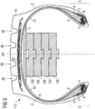
- FIG. 3 shows yet another embodiment in accordance with the invention in which a tire 110 has four layers 130 of open cell noise dampening foam strip material.
- a first layer 130 is attached to the innerliner 13 by means of a sealant layer 11.
- the sealant layer 11 acts as adhesive.
- Sealants are typically used to seal punctures in the tread 10, as for instance by screws or nails.
- Such sealant material is typically very sticky and known to the person skilled in the art.
- layers 130 are connected to each other by dove tail connections.
- each layer 130 has on one side a male element and on its opposite side a female element for mechanically interconnecting or fitting layers between each other.
- such interconnecting elements are provided in a center area of the layers 130.
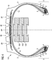
- Figure 4 shows another embodiment in accordance with the present invention in which a tire 111 has three layers 133 mechanically interconnected again by dove tail connectors.
- the male dove tale connector element of a first layer 133 is glued to the innerliner 13 of the tire.
- This configuration has the advantage that the male element has a smaller axial width than the whole axial width of the first layer 133 and creates a distance between the majority of the surface of the layer 133 facing the innerliner 13 below the tread. Thereby, a slot is created between the first layer 133 and the inner liner 13 which improves the cooling properties of the shown example.
- Said first layer 133 has a female dove tail connector element on a side of the layer 133 opposite to the side on which the male connector is arranged.
- the female connector is provided on a radially inner side of the layer 133
- the male connector is provided on a radially outer side of the layer 133. The same may apply respectively for one or more further layers attached to the first layer 133.
Landscapes
- Engineering & Computer Science (AREA)
- Mechanical Engineering (AREA)
- Tires In General (AREA)
- Tyre Moulding (AREA)
Abstract
Description
- The present invention is directed to a pneumatic tire comprising noise dampening foam strip material. Moreover, the present invention is directed to a method of manufacturing a noise dampened tire.
- Tires generate noise when driving. It is known in the art that at least a part of that noise may be dampened by including foam material within the tire cavity so as to dampen tire cavity noise. An example of such a noise dampening material is given in United States Patent Publication No.
20120125507 A1 in which a single layer of rubber foam is applied to the innerliner of a tire. However, relatively thick layers result in internal strains in the foam material due to flexing and bending, thereby resulting in limited durability as fatigue cracks may occur. In other examples, such as in United States Patent Publication No.20110030865 A1 tires are almost completely filled with foam. Filling essentially the whole tire cavity with foam is expensive and may also negatively affect cooling properties as well as driving performance of the tire. Noise dampening has recently become of even more importance in view of the growing number of electric vehicles which generate very little engine noise and accordingly which do not appreciably mask tire noise. Since tire noise is more noticeable in the operation of electric vehicles, such vehicles should optimally be equipped with tires that generate very little noise so that tire noise is not as evident. In the world today there continues to be a long felt need for tires that generate lower levels of noise during operation and there the demand for advanced noise cancellation technologies for pneumatic tires is higher than ever. However, significant room for improvement in this field of tire technology remains. - A first object of the invention may be to provide an advanced noise dampened pneumatic tire.
- Another object of the invention may be to provide an advanced noise dampened pneumatic tire which is relatively easy to produce at a commercially viable cost.
- Yet another object of the invention may be to provide an advanced noise dampened tire having a flexible noise dampening system adaptable to different tires, in particular different tire sizes.
- Still another object of the invention may be to provide a pneumatic tire with a foam noise dampener that allows a more homogeneous weight distribution and/or has less tensions within the dampening material.
- The scope of the present invention is defined by the independent claims. Preferred embodiments are listed in the dependent claims as well as in the following description.
- Thus, in a first aspect of the invention, a pneumatic tire is provided, the pneumatic tire comprising two spaced apart bead portions, a tread portion, a pair of sidewalls extending radially inward from axially outer edges of the tread portion to join the respective beads, the axially outer edges of the tread portion defining a tread width, a carcass, an innerliner covering the carcass and defining a tire cavity. Moreover, the tire comprises multiple layers of open cell noise dampening foam strip (material) attached on top of each other to the innerliner within the tire cavity in an area radially below the tread portion, wherein each layer has an axial width ranging from 20% (preferably 30%) to 80% of the tread width and a radial thickness ranging from 5% to 20% of the tread width and said multiple layers fill together from 8% (preferably 15%) to 40% of the volume of the tire cavity.
- Providing a plurality of layers of foam strip material on top of one another or in other words in a stacked manner or arrangement, may allow on the one hand to use same or similar strip material depending on the desired level of noise dampening and on the other hand to use the same or similar material for different tire sizes. Moreover, the desired amount of foam material for the tire cavity has been found by the inventors to constitute a good compromise between material cost, covered space and/or dampening properties. The open cell dampening material is much more suitable for dampening noise and/or vibration than closed cell foam material. In particular, an acoustic attenuation of tire cavity resonance is supported by the noise damping features of the present invention. Open cell noise damping foam material shall however not be understood herein as covering fully reticulated foam which constitutes merely a three-dimensional net, substantially free of cells or cell walls. While such material may have relatively good ventilation properties it is not suitable for dampening noise. Moreover, the latter material is relatively expensive. Another advantage of the present invention consists in the possibility to have multiple relatively thin layers arranged on top of each other instead of one thick layer. This helps to fix one or more ends of the layers in an easier manner as strain and/or bending forces are limited due to flexibility in each layer. The curvature of the tire is followed more easily by the plurality of the layers, wherein each of the layers have a different length (depending on the surface it is attached to). This results also in an easier installation procedure and reduces the risk that foam strips loosen from the innerliner. The risk of rupture of the strip material due to forces during mounting and/or use during tire life is reduced.
- In an embodiment, the open cell noise damping material has a density from 0.01 to 1 g/cm3, optionally from 0.02 to 0.5 g/cm3. Such material has turned out to be of particular interest.
- In another embodiment, the open cell noise damping foam strip material comprises from 55% to 95% (or preferably from 60% to 90%) open cells (of all cells) in the material. An open cell can be understood as a cell having at least one aperture. In other words, open cells are not fully closed or not fully enclosed by a cell wall. Closed cell foam does not fall into the above range as most cells of this foam type are closed. Fully or almost fully reticulated foam does not fall under that range either as it has almost no walls and constitutes rather an open grid. Whether cells are open or not (i.e. closed) can for instance be determined by light microscopy, SEM or NMR. Cell sizes could typically range from 10µm to 1mm (maximum diameter).
- In another embodiment, the density of the open cell noise damping foam strip material in a first layer contacting the innerliner is lower than a density of a second layer of open cell noise damping foam strip material attached to the first layer. Higher density may improve acoustic damping but allows for smaller thermal conduction which may negatively impact durability of the foam and/or the tire. A lower density open cell noise damping foam strip material may improve thermal conduction but has more limited acoustic damping characteristics.
- In still another embodiment, the foam material can be comprised of one or more of the following: polyurethane foam, polyethylene foam, foam rubber, and the like. Suitable polyurethane foams are typically made by the polymerization of a diisocyanate and a polyol in the presence of a suitable blowing agent. A wide variety of rubber foams can be utilized in the practice of this invention with natural rubber, synthetic polyisoprene rubber, polybutadiene rubber, nitrile rubber, and styrenebutadiene rubber foams being commonly used. Such foam rubbers are typically made by foaming a natural or synthetic rubber latex with a chemical foaming agent. The chemical foaming agent will typically be an azo compound, such as azodicarbonamide, a hydrazine compound, a carbazide, a tetrazole, a nitroso compound, and/or a carbonate, such as sodium bicarbonate.
- In another embodiment, the open cell noise damping foam strip material is adapted and/or used for dampening tire cavity noise, in particular in the range from 100 Hz to 300 Hz or in the range from 100 Hz to 200 Hz or from 200 Hz to 300 Hz.
- In another embodiment, the open cell noise damping foam strip material is (essentially) free of reticulated foam.
- In still another embodiment, said multiple layers are formed by a strip spirally wound on top of one another. An advantage of such an embodiment is the flexibility for application in mass production.
- In still another embodiment, a first layer of said multiple layers has a first butt splice arranged at a first circumferential position of the tire cavity, and a second layer of said multiple layers has a second butt splice arranged at a second circumferential position of the tire cavity which is different from the first circumferential position. In other words, each layer may be made of a single piece of foam strip material provided in a circumferential direction within the tire cavity and closed at its two ends with a butt splice. In case of having just one butt splice in a tire having just a single layer of foam strip material (not in accordance with the present invention), the position of the splice may result in unbalances. Having multiple layers on top of each other with splices at different circumferential (or angular) position helps to reduce such unbalances.
- In another embodiment, the position of the second butt splice of the second layer is arranged at an angular position which is in the range of 100° to 260°, optionally between 130° and 230°, circumferentially shifted (or rotated) from an angular position of the first butt splice of the first layer. This makes clear that an essentially opposite arrangement may be of particular interest, e.g. to avoid unbalances. Moreover, splices positioned at the bottom of a stack of layers are protected by the layers above as the splices are not provided at the same angular position. The probability of loosening of a whole foam strip is thereby further reduced compared to the provision of one relatively thick strip.
- In yet another embodiment, the layers have one or more of: an axial width from 50% to 70% of the tread width and a radial thickness from 5% to 15% of the tread width and, optionally, fill together from 20% to 40% of the volume of the tire cavity. This combination of parameters has been found by the inventors as even more desirable. This does not necessarily mean (as for the broader ranges) that all layers have the same width and/or thickness. The term tire cavity, as mentioned herein, shall be understood as the volume enclosed by the innerliner of the tire (especially in an unmounted and uninflated state), and closed by an (imaginary) circumferential ring-shaped plane contacting the radially innermost edges of both bead portions.
- In another embodiment, the layers are arranged essentially in parallel to the equatorial plane of the tire and have each a length covering at least 80% of the inner circumference of the tire, preferably at least 90% or at least 99%. In particular, the layers may be continuously arranged - either on top of each other or spirally wound.
- In yet another embodiment, the number of layers is from 2 to 4 layers, preferably 2 or 3 layers. This number may provide a good compromise between flexibility and work amount needed to install the layers.
- In yet another embodiment, a first layer attached to the inner liner is longer than a second layer attached onto the first layer. In particular, the length of the radially innermost circumferential surface of the second layer is smaller than the length of the radially innermost circumferential surface of the first layer. As both layers have different lengths, stresses onto the strip material are smaller in the case of having a single relatively, radially thick layer.
- In still another embodiment, a first foam strip layer attached to the innerliner has a smaller axial width than a second layer arranged on top of (or in other words radially inside of) the foam strip layer attached to the inner liner. Such an embodiment may help to improve the cooling of the tread and/or crown area of the tire as less insulating material is directly attached to the innerliner. Preferably, the second layer has an at least 20% larger width than the first layer attached to the inner liner, and optionally at most 50% larger width than the first layer. Such an arrangement would not be possible with non-customized foam strip material when using only a single layer.
- In still another embodiment, at least two of said layers are mechanically interlocked (or form fit), in other words they are connected to one another along their length. This allows avoidance of adhesive materials and glues, thereby reducing the ecological footprint and simplifying production. Preferably, said interlocking is essentially continuous over the length of the strip.
- In still another embodiment, said layers are mechanically interlocked by one or more of: dove tail connection(s), hook-and-loop-connections such as a Velcro connection, plastic pins extending through said layers and having lateral protrusions on both ends so as to hold said layers together. Dove tail connectors may in general cover also T-shaped connectors.
- In still another embodiment, at least one of the layers has a butt splice mechanically interlocked at its meeting face sides. This may also help to avoid gluing. For instance, above mentioned means for interlocking could be used.
- In still another embodiment, the tire is free of sealant material, in particular free of sealant material on the innerliner.
- In still another embodiment, the layers are interconnected to one another by at least one of: glue, hook-and-loop-connection tape such as Velcro tape, adhesive tape, double-sided adhesive tape, plastic connectors, plastic screws.
- In yet another embodiment, a radially outermost foam strip material layer is attached to the innerliner by at least one of a sealant material and an adhesive. In case the tire has sealant on the innerliner in the tire cavity, this sealant material can be used as adhesive.
- In yet another embodiment, at least one of the layers is coated with metal. A metal coating helps to guide heat away from hot spots. This may be of particular interest for the surfaces of the layer facing and/or attached to the innerliner of the tire. The metal coating can be done by various methods such as metallization, galvanic coating, sputtering, chemical vapor deposition and/or foil coating,
- In yet another embodiment, at least two layers have one or more of: the same radial thickness and the same radial width, wherein said multiple layers are optionally made of the same material. Such parameters may help to reduce costs and/or facilitate mounting.
- In an embodiment, the tire is one of: a truck tire, a bus tire, a passenger car tire. In particular, vehicles having closed cabins may benefit from the invention as the noise level inside the passenger cabin can be reduced. For example, the tire is a bus tire for a rim size of 22.5 inch.
- In a second aspect of the invention, a tire rim assembly (or wheel) is provided, the assembly comprising a rim and a tire mounted to the rim, wherein the tire comprises two spaced apart beads, a tread portion, a pair of sidewalls extending radially inward from axially outer edges of the tread portion to join the respective beads, wherein the axially outer edges of the tread portion define a tread width, a carcass, an innerliner covering the carcass and enclosing a tire cavity together with the rim. Moreover, said tire comprises multiple layers of open cell noise damping foam strip material attached on top of each other to the innerliner within the tire cavity in an area radially below the tread portion, wherein a single layer has an axial width from 30% to 80% of the tread width and a radial thickness from 5% to 20% of the tread width and said multiple layers together fill from 15% to 45% of the volume of the tire cavity.
- In a third aspect of the invention, a method of manufacturing a foam dampened pneumatic tire is provided, the method comprising the steps of: providing a pneumatic tire having a tire cavity; attaching a first layer of open cell, noise damping foam strip material circumferentially to an innerliner of the tire; attaching a second layer of open cell noise damping foam strip material onto the first layer. In an embodiment, the method further comprises the step of attaching a third layer onto the second layer.
- In another embodiment, the method further comprises the step of providing a first strip of the open cell noise damping foam strip material and attaching the first strip circumferentially to the innerliner of the tire and optionally closing the first strip at its two ends by a butt splice.
- In another embodiment, the method further comprises the step of providing a second strip of the open cell noise damping foam strip material and attaching the second strip circumferentially onto the first strip and optionally closing the second strip at its two ends by a butt splice, and wherein, optionally, the second strip is shorter than the first strip.
- In another embodiment, the butt splice of the second layer is arranged at an angular position which ranges from 100° to 260°, optionally from 130° to 230°, circumferentially shifted (or rotated) from an angular position of the first butt splice of the first layer.
- In another embodiment, a strip of open cell noise damping foam strip material is provided, which is longer than the inner circumference of the tire, and the strip is spirally applied in parallel to the equatorial plane of the tire so as to form at least two (or at least three) layers of the open cell noise damping foam strip material radially on top of one another.
- The words damping and dampening shall be replaceable within the present disclosure.
- It is emphasized that one or more aspects, embodiments, or features thereof, maybe be combined with each other within the scope of the present invention.
- The structure, operation and advantages of the invention will become more apparent upon contemplation of the following description taken in conjunction with the accompanying drawings, wherein:
-
Figure 1 shows a schematic cross-section of a truck or bus tire having two layers of foam material in accordance with an embodiment of the present invention; -
Figure 2 shows a schematic cross-section of another truck or bus tire having two layers of foam material with different axial width in accordance with another embodiment of the present invention; -
Figure 3 shows a schematic cross-section of another truck or bus tire having four layers of foam material connected along the strip length by dove tail connections and bound to the innerliner of the tire by a sealant layer, all in accordance with yet another embodiment of the present invention; -
Figure 4 shows a schematic cross-section of yet another truck or bus tire in accordance with yet another embodiment of the present invention and having three layers of foam material connected along the strip length by dove tail connections with a male end of the first layer glued to the innerliner of the tire; -
Figure 5 shows a schematic cross-section in parallel to the equatorial plane of the tire showing two layers of open cell noise damping foam strip material, wherein each layer has a butt splice (the tire as such is not shown in this Figure); and -
Figure 6 shows a schematic cross-section in parallel to the equatorial plane of the tire showing two spirally wound layers of open cell noise damping foam strip material, wherein each layer has a butt splice (the tire as such is not shown in this Figure); -
Figure 1 is a schematic cross-section of a bus ortruck tire 1. Thetire 1 has a tread 10 (or in other words a tread portion), aninner liner 13, a belt structure comprising a plurality of belt plies 12, acarcass ply 9, twosidewalls 2, and twobead regions 3 comprisingbead filler apexes 5 andbeads 4. The carcass ply 9 includes a pair of axiallyopposite end portions 6, each of which is associated with a respective one of thebeads 4. Eachaxial end portion 6 of thecarcass ply 9 may be turned up and around therespective bead 4 to a position to anchor eachaxial end portion 6. The turned-upportions 6 of thecarcass ply 9 may engage the axial outer surfaces of twoflippers 8 and axial inner surfaces of twochippers 7. As shown inFigure 1 , theexample tread 10 may have fourcircumferential grooves 20, each groove essentially defining a U-shaped opening in thetread 10. In accordance with a first embodiment of the invention, thetire 1 comprises two (stacked) layers 30 of a noise damping foam strip material. They are attached to the radially inner side of theinnerliner 13, preferably by means of a glue such as Loctite® from Henkel, for instance the 5900 series including 5900, 5910 and 5970. Both layers 30 are essentially arranged in the circumferential direction in parallel to the equatorial plane EP of thetire 1. The radial direction r, the circumferential direction c and the axial direction a have been indicated for the sake for easier reference. It is noted however, that the depicted orientations of the axial direction a and the circumferential direction c shall not be limiting the invention. The volume covered by the twolayers 20 shall be in accordance with the invention at least 8% (preferably 15%) of the tire cavity volume but less than 40% of the latter. The volume of the tire cavity shall be understood as the volume enclosed by the innerliner of the tire (especially in an unmounted and uninflated state) and closed by an (imaginary) circumferential ring-shaped plane contacting the radially innermost edges of bothbead portions 3. That plane is schematically shown inFigure 1 by a dashed line connecting the radially innermost edges of thetire 1. - As shown in
Figure 5 , each layer of multiple layers may be wound in the circumferential direction, wherein eachlayer 30 may have abutt splice 31. Preferably, butt splices ofdifferent layers 30 are not provided at same angular positions but are for instance mounted opposite to each other as shown inFigure 5 (shifted by 180° with respect to the circumferential direction). For the sake of clarity, thetire 1 as such is not shown inFigure 5 . The axial direction a is indicated in the center of the circumferentially arranged layers 30. - Alternatively, and as depicted in
Figure 6 , multiple layers 30' could be spirally wound on top of each other. This limits the number of splices and simplifies mounting. As in other embodiments, multiple layers 30' may for instance be glued to one another. Alternatively, other means may be used such as adhesive tapes or for instance Velcro connections. Further options are described in the context of other embodiments. - While the embodiment of
Figure 1 suggests a plurality of tire components including forinstance apexes 5,chippers 7 andflippers 8, such components are not mandatory for the invention. Also, the turned-up end of thecarcass ply 9 is not necessary for the invention or may pass on the opposite side of thebead area 3 and end on the axially inner side of thebead 4 instead of the axially outer side of thebead 4. The tire could also have for instance more or less than four grooves or a different number of belt plies than depicted. -
Figure 2 shows another example of atire 101 which hasmultiple layers 103, 103' of open cell noise dampening foam strip material. For the sake of easier reference, the same reference numerals as inFigure 1 have been used for other elements of thetire 101. The same applies toFigures 3 and4 respectively. In contrast to the embodiment ofFigure 1 ,Figure 2 shows afirst layer 103 of open cell noise dampening foam strip material which has a first axial width and a second layer 103' which has a second, larger axial width than thefirst layer 103. This arrangement may help to improve cooling of the tire in an area below thetread 10. This effect may be further improved by providing an open cell noise dampening foam strip material with lower density inlayer 103 than in layer 103'. Thus, layer 103' may have better noise dampening properties thanlayer 103 while allowing a better cooling of the tread area than in the arrangement shown inFigure 1 . -
Figure 3 shows yet another embodiment in accordance with the invention in which atire 110 has fourlayers 130 of open cell noise dampening foam strip material. Afirst layer 130 is attached to theinnerliner 13 by means of asealant layer 11. Thus, thesealant layer 11 acts as adhesive. Sealants are typically used to seal punctures in thetread 10, as for instance by screws or nails. Such sealant material is typically very sticky and known to the person skilled in the art. Instead of gluingmultiple layers 130 to one another, layers 130 are connected to each other by dove tail connections. In particular, eachlayer 130 has on one side a male element and on its opposite side a female element for mechanically interconnecting or fitting layers between each other. Preferably, such interconnecting elements are provided in a center area of thelayers 130. This modular system allows easy adding of layers in dependence of the actual tire. Glues are avoided completely in this embodiment. -
Figure 4 shows another embodiment in accordance with the present invention in which atire 111 has threelayers 133 mechanically interconnected again by dove tail connectors. In this embodiment, the male dove tale connector element of afirst layer 133 is glued to theinnerliner 13 of the tire. This configuration has the advantage that the male element has a smaller axial width than the whole axial width of thefirst layer 133 and creates a distance between the majority of the surface of thelayer 133 facing theinnerliner 13 below the tread. Thereby, a slot is created between thefirst layer 133 and theinner liner 13 which improves the cooling properties of the shown example. Saidfirst layer 133 has a female dove tail connector element on a side of thelayer 133 opposite to the side on which the male connector is arranged. In other words, the female connector is provided on a radially inner side of thelayer 133, whereas the male connector is provided on a radially outer side of thelayer 133. The same may apply respectively for one or more further layers attached to thefirst layer 133.
Claims (15)
- A pneumatic tire (1), comprising two spaced apart bead portions (3), a tread portion, a pair of sidewalls (2) extending radially inward from axially outer edges of the tread portion to join the respective bead portions (3), the axially outer edges of the tread portion defining a tread width, a carcass (9), an innerliner (13) covering the carcass (9) and defining a tire cavity, and
multiple layers (30, 30', 103, 103', 130, 133) of open cell noise damping foam strip material attached on top of one another to the innerliner (13) within the tire cavity in an area radially below the tread portion, wherein each layer (30, 30', 103, 103', 130, 133) has an axial width from 20% to 80% of the tread width and a radial thickness from 5% to 20% of the tread width and said multiple layers (30, 30', 103, 103', 130, 133) fill together from 8% to 40% of the volume of the tire cavity. - The tire according to claim 1, characterized in that the open cell noise damping foam strip material has a density ranging from 0.01 g/cm3 to 1 g/cm3.
- The tire according to claim 1 or claim 2, characterized in that said multiple layers (30, 30', 103, 103', 130, 133) are integrally formed and spirally wound on top of one another in the tire cavity.
- The tire according to one or more of the preceding claims, characterized in that a first layer of said multiple layers (30, 30', 103, 103', 130, 133) has a first butt splice (31) arranged at a first circumferential position of the tire cavity, and wherein a second layer of said multiple layers has a second butt splice (31) arranged at a second circumferential position of the tire cavity which is different from the first circumferential position, wherein, optionally, the position of the second butt splice of the second layer is arranged at an angular position which is between 100° and 260° circumferentially shifted from an angular position of the first butt splice of the first layer.
- The tire according to one or more of the preceding claims, characterized in that the layers (30, 30', 103, 103', 130, 133) have one or more of: an axial width ranging from 50% to 70% of the tread width, a radial thickness ranging from 5% to 15% of the tread width, and/or fill together from 20% to 40% of the volume of the tire cavity.
- The tire according to one or more of the preceding claims, characterized in that each of the layers (30, 30', 103, 103', 130, 133) is arranged essentially in parallel to the equatorial plane (EP) of the tire and/or has a length covering at least 80% of the inner circumference of the tire.
- The tire according to one or more of the preceding claims, characterized in that a first foam strip material layer (103) attached to the innerliner (13) has a smaller axial width than a second foam strip material layer (103') arranged on top of the first foam strip material layer (103) attached to the inner liner (13).
- The tire according to one or more of the preceding claims, characterized in that at least two of said layers (130) are mechanically interlocked to one another along their length, wherein said interlocking is optionally essentially continuous over the length of the foam strip material between two layers attached on top of each other; and/or wherein said layers are optionally mechanically interlocked by one or more of: one or more dove tail connections, one or more jigsaw connections, hook-and-loop fasteners, plastic rivets, and plastic screws.
- The tire according to one or more of the preceding claims, characterized in that at least one of the layers has a butt splice (31) mechanically interlocked at its meeting face sides.
- The tire according to one or more of the preceding claims, characterized in that the layers (30, 30', 103, 103', 130, 133) are interconnected to one another by at least one of: glue, hook-and-loop fastener tape, adhesive tape, double-sided adhesive tape, plastic rivets, and plastic screws; and/or wherein a radially outermost foam strip material layer is optionally attached to the innerliner (13) by at least one of a sealant material and an adhesive.
- The tire according to one or more of the preceding claims, characterized in that at least one of the layers (30, 30', 103, 103', 130, 133) is coated with metal.
- The tire according to one or more of the preceding claims, characterized in that at least two layers (30, 30', 103, 103', 130, 133) comprise one or more of: same radial thickness, same radial width, and same foam strip material.
- The tire according to one or more of the preceding claims, characterized in that the tire is a bus tire for a rim size of 22.5 inch.
- The tire according to one or more of the preceding claims, characterized in that the open cell noise damping foam strip material is comprised of one or more of the following materials: polyurethane foam, polyethylene foam and foam rubber.
- A method of manufacturing a foam dampened pneumatic tire, in particular the tire according to one or more of the preceding claims, characterized in that the method comprises at least the steps of: providing a pneumatic tire having a tire cavity; attaching a first layer of open cell noise damping foam strip material circumferentially to an innerliner (13) of the tire; attaching a second layer of open cell noise damping foam strip material onto the first layer.
Applications Claiming Priority (1)
| Application Number | Priority Date | Filing Date | Title |
|---|---|---|---|
| US201962943417P | 2019-12-04 | 2019-12-04 |
Publications (2)
| Publication Number | Publication Date |
|---|---|
| EP3831620A1 true EP3831620A1 (en) | 2021-06-09 |
| EP3831620B1 EP3831620B1 (en) | 2023-04-19 |
Family
ID=73654693
Family Applications (1)
| Application Number | Title | Priority Date | Filing Date |
|---|---|---|---|
| EP20210942.7A Active EP3831620B1 (en) | 2019-12-04 | 2020-12-01 | A pneumatic tire |
Country Status (4)
| Country | Link |
|---|---|
| US (1) | US11912072B2 (en) |
| EP (1) | EP3831620B1 (en) |
| JP (1) | JP7692261B2 (en) |
| CN (1) | CN112895815B (en) |
Cited By (2)
| Publication number | Priority date | Publication date | Assignee | Title |
|---|---|---|---|---|
| WO2023021300A1 (en) * | 2021-08-19 | 2023-02-23 | Carbon Air Limited | A vehicle wheel |
| EP4450302A4 (en) * | 2021-12-15 | 2025-10-22 | Hankook Tire & Tech Co Ltd | TIRES WITH SEALANT LAYER AND SOUND-ABSORBING MATERIAL LAYER |
Families Citing this family (5)
| Publication number | Priority date | Publication date | Assignee | Title |
|---|---|---|---|---|
| JP7822044B2 (en) * | 2022-05-11 | 2026-03-02 | 株式会社アサヒテクノ | Cell Killing System |
| CN116278529B (en) * | 2023-03-27 | 2025-06-03 | 青岛双星轮胎工业有限公司 | A low-noise pneumatic tire and a manufacturing method thereof |
| DE102024208470A1 (en) * | 2024-09-05 | 2026-03-05 | Continental Reifen Deutschland Gmbh | Method for manufacturing a low-noise vehicle pneumatic tire and low-noise vehicle pneumatic tires |
| WO2026055953A1 (en) * | 2024-09-14 | 2026-03-19 | Henkel Ag & Co. Kgaa | Vehicle tire having foam multilayer structure on inner wall of body of vehicle tire and method for manufacturing vehicle tire |
| WO2026055954A1 (en) * | 2024-09-14 | 2026-03-19 | Henkel Ag & Co. Kgaa | Vehicle tire |
Citations (5)
| Publication number | Priority date | Publication date | Assignee | Title |
|---|---|---|---|---|
| EP1795378A2 (en) * | 2005-12-08 | 2007-06-13 | Sumitomo Rubber Industries Ltd. | Pneumatic tire with noise damper |
| US20110030865A1 (en) | 2006-12-19 | 2011-02-10 | The Goodyear Tire & Rubber Company | Foam filled tire |
| US20120125507A1 (en) | 2010-11-24 | 2012-05-24 | Bormann Rene Louis | Tire with foamed noise damper |
| DE112016000556T5 (en) * | 2015-01-29 | 2017-11-02 | The Yokohama Rubber Co., Ltd. | tire |
| EP3431309A1 (en) * | 2016-12-28 | 2019-01-23 | Sumitomo Rubber Industries, Ltd. | Pneumatic tire |
Family Cites Families (27)
| Publication number | Priority date | Publication date | Assignee | Title |
|---|---|---|---|---|
| DE1276485B (en) * | 1961-06-23 | 1968-08-29 | Continental Gummi Werke Ag | Pneumatic vehicle tires with a belt |
| JPS58185305A (en) * | 1982-04-24 | 1983-10-29 | Sumitomo Rubber Ind Ltd | Safety tire |
| JP2790982B2 (en) * | 1994-11-15 | 1998-08-27 | 住友ゴム工業株式会社 | Pneumatic radial tire |
| JP3622957B2 (en) | 2001-08-02 | 2005-02-23 | 住友ゴム工業株式会社 | Pneumatic tire and rim assembly |
| EP1852279B1 (en) * | 2004-03-16 | 2009-06-03 | Sumitomo Rubber Industries Ltd. | Pneumatic tire with a plurality of noise dampers |
| JP2007154566A (en) | 2005-12-07 | 2007-06-21 | Sekisui Chem Co Ltd | Fireproof compartment penetration structure |
| JP4833783B2 (en) * | 2006-09-26 | 2011-12-07 | 横浜ゴム株式会社 | Tire noise reduction device and pneumatic tire |
| JP4338761B2 (en) * | 2008-01-29 | 2009-10-07 | 住友ゴム工業株式会社 | Pneumatic tire with sound control |
| DE102009024454A1 (en) * | 2009-06-10 | 2010-12-16 | Audi Ag | tire |
| JP4983876B2 (en) * | 2009-09-11 | 2012-07-25 | 横浜ゴム株式会社 | Tire noise reduction device and pneumatic tire provided with the same |
| US20110308706A1 (en) | 2010-06-21 | 2011-12-22 | The Goodyear Tire & Rubber Company | Method for making pneumatic tire with foam noise damper |
| US20110308705A1 (en) | 2010-06-21 | 2011-12-22 | Paul Harry Sandstrom | Method for making pneumatic tire with foam noise damper |
| US20120073717A1 (en) | 2010-09-24 | 2012-03-29 | Giorgio Agostini | Method for making pneumatic tire with foam noise damper |
| US20120125525A1 (en) | 2010-11-24 | 2012-05-24 | Ramendra Nath Majumdar | Method for making pneumatic tire with foam noise damper |
| US20130032262A1 (en) | 2011-08-02 | 2013-02-07 | Bormann Rene Louis | Tire with foamed noise damper |
| KR20130022893A (en) | 2011-08-26 | 2013-03-07 | 한국타이어월드와이드 주식회사 | Pneumatic tire and manufacturing method thereof |
| US8888939B2 (en) | 2012-10-31 | 2014-11-18 | The Goodyear Tire & Rubber Company | Method of applying an annular strip to a tire |
| WO2018105421A1 (en) | 2016-12-07 | 2018-06-14 | 住友ゴム工業株式会社 | Pneumatic tire |
| WO2018116835A1 (en) | 2016-12-20 | 2018-06-28 | 住友ゴム工業株式会社 | Pneumatic tire |
| DE102017210912A1 (en) * | 2017-06-28 | 2019-01-03 | Continental Reifen Deutschland Gmbh | Pneumatic vehicle tire having an acoustic element |
| DE102017210916A1 (en) * | 2017-06-28 | 2019-01-03 | Continental Reifen Deutschland Gmbh | Vehicle wheel component comprising an acoustic element |
| DE102017210931A1 (en) * | 2017-06-28 | 2019-01-03 | Continental Reifen Deutschland Gmbh | Vehicle tires |
| DE102017210926A1 (en) * | 2017-06-28 | 2019-01-03 | Continental Reifen Deutschland Gmbh | Vehicle tires |
| JP6853751B2 (en) | 2017-08-14 | 2021-03-31 | 株式会社ブリヂストン | Pneumatic tires |
| GB201721970D0 (en) | 2017-12-27 | 2018-02-07 | Apollo Tyres Global R & D Bv | Noise reducing tyre |
| WO2019221874A1 (en) * | 2018-05-15 | 2019-11-21 | Bridgestone Americas Tire Operations, Llc | Tire with multi-layer insert |
| JP2020093680A (en) * | 2018-12-13 | 2020-06-18 | 株式会社ブリヂストン | Pneumatic radial tires for passenger cars |
-
2020
- 2020-12-01 EP EP20210942.7A patent/EP3831620B1/en active Active
- 2020-12-03 US US17/110,963 patent/US11912072B2/en active Active
- 2020-12-04 CN CN202011406573.6A patent/CN112895815B/en active Active
- 2020-12-04 JP JP2020201849A patent/JP7692261B2/en active Active
Patent Citations (5)
| Publication number | Priority date | Publication date | Assignee | Title |
|---|---|---|---|---|
| EP1795378A2 (en) * | 2005-12-08 | 2007-06-13 | Sumitomo Rubber Industries Ltd. | Pneumatic tire with noise damper |
| US20110030865A1 (en) | 2006-12-19 | 2011-02-10 | The Goodyear Tire & Rubber Company | Foam filled tire |
| US20120125507A1 (en) | 2010-11-24 | 2012-05-24 | Bormann Rene Louis | Tire with foamed noise damper |
| DE112016000556T5 (en) * | 2015-01-29 | 2017-11-02 | The Yokohama Rubber Co., Ltd. | tire |
| EP3431309A1 (en) * | 2016-12-28 | 2019-01-23 | Sumitomo Rubber Industries, Ltd. | Pneumatic tire |
Cited By (2)
| Publication number | Priority date | Publication date | Assignee | Title |
|---|---|---|---|---|
| WO2023021300A1 (en) * | 2021-08-19 | 2023-02-23 | Carbon Air Limited | A vehicle wheel |
| EP4450302A4 (en) * | 2021-12-15 | 2025-10-22 | Hankook Tire & Tech Co Ltd | TIRES WITH SEALANT LAYER AND SOUND-ABSORBING MATERIAL LAYER |
Also Published As
| Publication number | Publication date |
|---|---|
| CN112895815A (en) | 2021-06-04 |
| JP7692261B2 (en) | 2025-06-13 |
| CN112895815B (en) | 2023-03-31 |
| US20210170809A1 (en) | 2021-06-10 |
| EP3831620B1 (en) | 2023-04-19 |
| US11912072B2 (en) | 2024-02-27 |
| JP2021088355A (en) | 2021-06-10 |
Similar Documents
| Publication | Publication Date | Title |
|---|---|---|
| EP3831620B1 (en) | A pneumatic tire | |
| EP1967391B1 (en) | Method for manufacturing low noise pneumatic tire | |
| CN100554010C (en) | Air-inflation tyre with noise damper | |
| US8997806B2 (en) | Tire noise reduction device | |
| US8281834B2 (en) | Assembly of pneumatic tire, noise damper, and rim | |
| EP2452832B1 (en) | Pneumatic tire with an innerliner and method of making the same | |
| CN1899862B (en) | low noise tire | |
| EP1510366A1 (en) | Assembly of pneumatic tire and rim, sound suppressing body used for the assembly, and pneumatic tire storage method | |
| EP3670212B1 (en) | Pneumatic tire | |
| US20140246133A1 (en) | Tire containing a component for reducing vibration-generated noise in a tire and method for reducing tire noise | |
| WO2015111314A1 (en) | Pneumatic tire | |
| JP2010269734A (en) | Pneumatic tire | |
| EP3831621B1 (en) | A pneumatic tire | |
| EP3831622B1 (en) | A pneumatic tire | |
| US20090205770A1 (en) | Method Of Manufacturing A Pneumatic Tire | |
| WO2021214096A1 (en) | Pneumatic tyre | |
| EP3778267B1 (en) | Pneumatic tyre and method for the construction of said pneumatic tyre | |
| JPH06336103A (en) | Wheel equipped with pneumatic safety tire | |
| LU503431B1 (en) | Pneumatic tyre comprising sound absorbing device | |
| JP2002087003A (en) | wheel | |
| WO2020121572A1 (en) | Pneumatic radial tire for passenger vehicles | |
| JP2019051773A (en) | Pneumatic tire and assembly | |
| US20220250421A1 (en) | Pneumatic tire |
Legal Events
| Date | Code | Title | Description |
|---|---|---|---|
| PUAI | Public reference made under article 153(3) epc to a published international application that has entered the european phase |
Free format text: ORIGINAL CODE: 0009012 |
|
| STAA | Information on the status of an ep patent application or granted ep patent |
Free format text: STATUS: THE APPLICATION HAS BEEN PUBLISHED |
|
| AK | Designated contracting states |
Kind code of ref document: A1 Designated state(s): AL AT BE BG CH CY CZ DE DK EE ES FI FR GB GR HR HU IE IS IT LI LT LU LV MC MK MT NL NO PL PT RO RS SE SI SK SM TR |
|
| STAA | Information on the status of an ep patent application or granted ep patent |
Free format text: STATUS: REQUEST FOR EXAMINATION WAS MADE |
|
| 17P | Request for examination filed |
Effective date: 20211209 |
|
| RBV | Designated contracting states (corrected) |
Designated state(s): AL AT BE BG CH CY CZ DE DK EE ES FI FR GB GR HR HU IE IS IT LI LT LU LV MC MK MT NL NO PL PT RO RS SE SI SK SM TR |
|
| RIC1 | Information provided on ipc code assigned before grant |
Ipc: B32B 7/04 20190101ALI20220906BHEP Ipc: B60C 19/00 20060101AFI20220906BHEP |
|
| GRAP | Despatch of communication of intention to grant a patent |
Free format text: ORIGINAL CODE: EPIDOSNIGR1 |
|
| STAA | Information on the status of an ep patent application or granted ep patent |
Free format text: STATUS: GRANT OF PATENT IS INTENDED |
|
| INTG | Intention to grant announced |
Effective date: 20221104 |
|
| GRAS | Grant fee paid |
Free format text: ORIGINAL CODE: EPIDOSNIGR3 |
|
| GRAA | (expected) grant |
Free format text: ORIGINAL CODE: 0009210 |
|
| STAA | Information on the status of an ep patent application or granted ep patent |
Free format text: STATUS: THE PATENT HAS BEEN GRANTED |
|
| AK | Designated contracting states |
Kind code of ref document: B1 Designated state(s): AL AT BE BG CH CY CZ DE DK EE ES FI FR GB GR HR HU IE IS IT LI LT LU LV MC MK MT NL NO PL PT RO RS SE SI SK SM TR |
|
| REG | Reference to a national code |
Ref country code: GB Ref legal event code: FG4D |
|
| REG | Reference to a national code |
Ref country code: CH Ref legal event code: EP |
|
| REG | Reference to a national code |
Ref country code: DE Ref legal event code: R096 Ref document number: 602020009851 Country of ref document: DE |
|
| REG | Reference to a national code |
Ref country code: IE Ref legal event code: FG4D |
|
| REG | Reference to a national code |
Ref country code: AT Ref legal event code: REF Ref document number: 1560921 Country of ref document: AT Kind code of ref document: T Effective date: 20230515 |
|
| REG | Reference to a national code |
Ref country code: LT Ref legal event code: MG9D |
|
| REG | Reference to a national code |
Ref country code: NL Ref legal event code: MP Effective date: 20230419 |
|
| REG | Reference to a national code |
Ref country code: AT Ref legal event code: MK05 Ref document number: 1560921 Country of ref document: AT Kind code of ref document: T Effective date: 20230419 |
|
| PG25 | Lapsed in a contracting state [announced via postgrant information from national office to epo] |
Ref country code: NL Free format text: LAPSE BECAUSE OF FAILURE TO SUBMIT A TRANSLATION OF THE DESCRIPTION OR TO PAY THE FEE WITHIN THE PRESCRIBED TIME-LIMIT Effective date: 20230419 |
|
| PG25 | Lapsed in a contracting state [announced via postgrant information from national office to epo] |
Ref country code: SE Free format text: LAPSE BECAUSE OF FAILURE TO SUBMIT A TRANSLATION OF THE DESCRIPTION OR TO PAY THE FEE WITHIN THE PRESCRIBED TIME-LIMIT Effective date: 20230419 Ref country code: PT Free format text: LAPSE BECAUSE OF FAILURE TO SUBMIT A TRANSLATION OF THE DESCRIPTION OR TO PAY THE FEE WITHIN THE PRESCRIBED TIME-LIMIT Effective date: 20230821 Ref country code: NO Free format text: LAPSE BECAUSE OF FAILURE TO SUBMIT A TRANSLATION OF THE DESCRIPTION OR TO PAY THE FEE WITHIN THE PRESCRIBED TIME-LIMIT Effective date: 20230719 Ref country code: ES Free format text: LAPSE BECAUSE OF FAILURE TO SUBMIT A TRANSLATION OF THE DESCRIPTION OR TO PAY THE FEE WITHIN THE PRESCRIBED TIME-LIMIT Effective date: 20230419 Ref country code: AT Free format text: LAPSE BECAUSE OF FAILURE TO SUBMIT A TRANSLATION OF THE DESCRIPTION OR TO PAY THE FEE WITHIN THE PRESCRIBED TIME-LIMIT Effective date: 20230419 |
|
| PG25 | Lapsed in a contracting state [announced via postgrant information from national office to epo] |
Ref country code: RS Free format text: LAPSE BECAUSE OF FAILURE TO SUBMIT A TRANSLATION OF THE DESCRIPTION OR TO PAY THE FEE WITHIN THE PRESCRIBED TIME-LIMIT Effective date: 20230419 Ref country code: PL Free format text: LAPSE BECAUSE OF FAILURE TO SUBMIT A TRANSLATION OF THE DESCRIPTION OR TO PAY THE FEE WITHIN THE PRESCRIBED TIME-LIMIT Effective date: 20230419 Ref country code: LV Free format text: LAPSE BECAUSE OF FAILURE TO SUBMIT A TRANSLATION OF THE DESCRIPTION OR TO PAY THE FEE WITHIN THE PRESCRIBED TIME-LIMIT Effective date: 20230419 Ref country code: LT Free format text: LAPSE BECAUSE OF FAILURE TO SUBMIT A TRANSLATION OF THE DESCRIPTION OR TO PAY THE FEE WITHIN THE PRESCRIBED TIME-LIMIT Effective date: 20230419 Ref country code: IS Free format text: LAPSE BECAUSE OF FAILURE TO SUBMIT A TRANSLATION OF THE DESCRIPTION OR TO PAY THE FEE WITHIN THE PRESCRIBED TIME-LIMIT Effective date: 20230819 Ref country code: HR Free format text: LAPSE BECAUSE OF FAILURE TO SUBMIT A TRANSLATION OF THE DESCRIPTION OR TO PAY THE FEE WITHIN THE PRESCRIBED TIME-LIMIT Effective date: 20230419 Ref country code: GR Free format text: LAPSE BECAUSE OF FAILURE TO SUBMIT A TRANSLATION OF THE DESCRIPTION OR TO PAY THE FEE WITHIN THE PRESCRIBED TIME-LIMIT Effective date: 20230720 Ref country code: AL Free format text: LAPSE BECAUSE OF FAILURE TO SUBMIT A TRANSLATION OF THE DESCRIPTION OR TO PAY THE FEE WITHIN THE PRESCRIBED TIME-LIMIT Effective date: 20230419 |
|
| PG25 | Lapsed in a contracting state [announced via postgrant information from national office to epo] |
Ref country code: FI Free format text: LAPSE BECAUSE OF FAILURE TO SUBMIT A TRANSLATION OF THE DESCRIPTION OR TO PAY THE FEE WITHIN THE PRESCRIBED TIME-LIMIT Effective date: 20230419 |
|
| PG25 | Lapsed in a contracting state [announced via postgrant information from national office to epo] |
Ref country code: SK Free format text: LAPSE BECAUSE OF FAILURE TO SUBMIT A TRANSLATION OF THE DESCRIPTION OR TO PAY THE FEE WITHIN THE PRESCRIBED TIME-LIMIT Effective date: 20230419 |
|
| REG | Reference to a national code |
Ref country code: DE Ref legal event code: R097 Ref document number: 602020009851 Country of ref document: DE |
|
| PG25 | Lapsed in a contracting state [announced via postgrant information from national office to epo] |
Ref country code: SM Free format text: LAPSE BECAUSE OF FAILURE TO SUBMIT A TRANSLATION OF THE DESCRIPTION OR TO PAY THE FEE WITHIN THE PRESCRIBED TIME-LIMIT Effective date: 20230419 Ref country code: SK Free format text: LAPSE BECAUSE OF FAILURE TO SUBMIT A TRANSLATION OF THE DESCRIPTION OR TO PAY THE FEE WITHIN THE PRESCRIBED TIME-LIMIT Effective date: 20230419 Ref country code: RO Free format text: LAPSE BECAUSE OF FAILURE TO SUBMIT A TRANSLATION OF THE DESCRIPTION OR TO PAY THE FEE WITHIN THE PRESCRIBED TIME-LIMIT Effective date: 20230419 Ref country code: EE Free format text: LAPSE BECAUSE OF FAILURE TO SUBMIT A TRANSLATION OF THE DESCRIPTION OR TO PAY THE FEE WITHIN THE PRESCRIBED TIME-LIMIT Effective date: 20230419 Ref country code: DK Free format text: LAPSE BECAUSE OF FAILURE TO SUBMIT A TRANSLATION OF THE DESCRIPTION OR TO PAY THE FEE WITHIN THE PRESCRIBED TIME-LIMIT Effective date: 20230419 Ref country code: CZ Free format text: LAPSE BECAUSE OF FAILURE TO SUBMIT A TRANSLATION OF THE DESCRIPTION OR TO PAY THE FEE WITHIN THE PRESCRIBED TIME-LIMIT Effective date: 20230419 |
|
| PLBE | No opposition filed within time limit |
Free format text: ORIGINAL CODE: 0009261 |
|
| STAA | Information on the status of an ep patent application or granted ep patent |
Free format text: STATUS: NO OPPOSITION FILED WITHIN TIME LIMIT |
|
| 26N | No opposition filed |
Effective date: 20240122 |
|
| PG25 | Lapsed in a contracting state [announced via postgrant information from national office to epo] |
Ref country code: SI Free format text: LAPSE BECAUSE OF FAILURE TO SUBMIT A TRANSLATION OF THE DESCRIPTION OR TO PAY THE FEE WITHIN THE PRESCRIBED TIME-LIMIT Effective date: 20230419 |
|
| PG25 | Lapsed in a contracting state [announced via postgrant information from national office to epo] |
Ref country code: SI Free format text: LAPSE BECAUSE OF FAILURE TO SUBMIT A TRANSLATION OF THE DESCRIPTION OR TO PAY THE FEE WITHIN THE PRESCRIBED TIME-LIMIT Effective date: 20230419 |
|
| REG | Reference to a national code |
Ref country code: CH Ref legal event code: PL |
|
| PG25 | Lapsed in a contracting state [announced via postgrant information from national office to epo] |
Ref country code: LU Free format text: LAPSE BECAUSE OF NON-PAYMENT OF DUE FEES Effective date: 20231201 |
|
| PG25 | Lapsed in a contracting state [announced via postgrant information from national office to epo] |
Ref country code: MC Free format text: LAPSE BECAUSE OF FAILURE TO SUBMIT A TRANSLATION OF THE DESCRIPTION OR TO PAY THE FEE WITHIN THE PRESCRIBED TIME-LIMIT Effective date: 20230419 |
|
| REG | Reference to a national code |
Ref country code: BE Ref legal event code: MM Effective date: 20231231 |
|
| PG25 | Lapsed in a contracting state [announced via postgrant information from national office to epo] |
Ref country code: MC Free format text: LAPSE BECAUSE OF FAILURE TO SUBMIT A TRANSLATION OF THE DESCRIPTION OR TO PAY THE FEE WITHIN THE PRESCRIBED TIME-LIMIT Effective date: 20230419 Ref country code: LU Free format text: LAPSE BECAUSE OF NON-PAYMENT OF DUE FEES Effective date: 20231201 |
|
| REG | Reference to a national code |
Ref country code: IE Ref legal event code: MM4A |
|
| PG25 | Lapsed in a contracting state [announced via postgrant information from national office to epo] |
Ref country code: IE Free format text: LAPSE BECAUSE OF NON-PAYMENT OF DUE FEES Effective date: 20231201 |
|
| PG25 | Lapsed in a contracting state [announced via postgrant information from national office to epo] |
Ref country code: BE Free format text: LAPSE BECAUSE OF NON-PAYMENT OF DUE FEES Effective date: 20231231 |
|
| PG25 | Lapsed in a contracting state [announced via postgrant information from national office to epo] |
Ref country code: CH Free format text: LAPSE BECAUSE OF NON-PAYMENT OF DUE FEES Effective date: 20231231 |
|
| PG25 | Lapsed in a contracting state [announced via postgrant information from national office to epo] |
Ref country code: IE Free format text: LAPSE BECAUSE OF NON-PAYMENT OF DUE FEES Effective date: 20231201 Ref country code: CH Free format text: LAPSE BECAUSE OF NON-PAYMENT OF DUE FEES Effective date: 20231231 Ref country code: BE Free format text: LAPSE BECAUSE OF NON-PAYMENT OF DUE FEES Effective date: 20231231 |
|
| PG25 | Lapsed in a contracting state [announced via postgrant information from national office to epo] |
Ref country code: BG Free format text: LAPSE BECAUSE OF FAILURE TO SUBMIT A TRANSLATION OF THE DESCRIPTION OR TO PAY THE FEE WITHIN THE PRESCRIBED TIME-LIMIT Effective date: 20230419 |
|
| PG25 | Lapsed in a contracting state [announced via postgrant information from national office to epo] |
Ref country code: BG Free format text: LAPSE BECAUSE OF FAILURE TO SUBMIT A TRANSLATION OF THE DESCRIPTION OR TO PAY THE FEE WITHIN THE PRESCRIBED TIME-LIMIT Effective date: 20230419 |
|
| PG25 | Lapsed in a contracting state [announced via postgrant information from national office to epo] |
Ref country code: CY Free format text: LAPSE BECAUSE OF FAILURE TO SUBMIT A TRANSLATION OF THE DESCRIPTION OR TO PAY THE FEE WITHIN THE PRESCRIBED TIME-LIMIT; INVALID AB INITIO Effective date: 20201201 |
|
| PG25 | Lapsed in a contracting state [announced via postgrant information from national office to epo] |
Ref country code: HU Free format text: LAPSE BECAUSE OF FAILURE TO SUBMIT A TRANSLATION OF THE DESCRIPTION OR TO PAY THE FEE WITHIN THE PRESCRIBED TIME-LIMIT; INVALID AB INITIO Effective date: 20201201 |
|
| GBPC | Gb: european patent ceased through non-payment of renewal fee |
Effective date: 20241201 |
|
| PG25 | Lapsed in a contracting state [announced via postgrant information from national office to epo] |
Ref country code: GB Free format text: LAPSE BECAUSE OF NON-PAYMENT OF DUE FEES Effective date: 20241201 |
|
| PG25 | Lapsed in a contracting state [announced via postgrant information from national office to epo] |
Ref country code: TR Free format text: LAPSE BECAUSE OF FAILURE TO SUBMIT A TRANSLATION OF THE DESCRIPTION OR TO PAY THE FEE WITHIN THE PRESCRIBED TIME-LIMIT Effective date: 20230419 |
|
| PGFP | Annual fee paid to national office [announced via postgrant information from national office to epo] |
Ref country code: DE Payment date: 20251113 Year of fee payment: 6 |
|
| PGFP | Annual fee paid to national office [announced via postgrant information from national office to epo] |
Ref country code: IT Payment date: 20251119 Year of fee payment: 6 |
|
| PGFP | Annual fee paid to national office [announced via postgrant information from national office to epo] |
Ref country code: FR Payment date: 20251120 Year of fee payment: 6 |