EP3831541B1 - Exoskeleton system, control device and control method - Google Patents
Exoskeleton system, control device and control method Download PDFInfo
- Publication number
- EP3831541B1 EP3831541B1 EP20165492.8A EP20165492A EP3831541B1 EP 3831541 B1 EP3831541 B1 EP 3831541B1 EP 20165492 A EP20165492 A EP 20165492A EP 3831541 B1 EP3831541 B1 EP 3831541B1
- Authority
- EP
- European Patent Office
- Prior art keywords
- exoskeleton system
- terrain
- moving direction
- branch
- sensing unit
- Prior art date
- Legal status (The legal status is an assumption and is not a legal conclusion. Google has not performed a legal analysis and makes no representation as to the accuracy of the status listed.)
- Active
Links
Images




Classifications
-
- B—PERFORMING OPERATIONS; TRANSPORTING
- B25—HAND TOOLS; PORTABLE POWER-DRIVEN TOOLS; MANIPULATORS
- B25J—MANIPULATORS; CHAMBERS PROVIDED WITH MANIPULATION DEVICES
- B25J9/00—Program-controlled manipulators
- B25J9/0006—Exoskeletons, i.e. resembling a human figure
-
- A—HUMAN NECESSITIES
- A61—MEDICAL OR VETERINARY SCIENCE; HYGIENE
- A61H—PHYSICAL THERAPY APPARATUS, e.g. DEVICES FOR LOCATING OR STIMULATING REFLEX POINTS IN THE BODY; ARTIFICIAL RESPIRATION; MASSAGE; BATHING DEVICES FOR SPECIAL THERAPEUTIC OR HYGIENIC PURPOSES OR SPECIFIC PARTS OF THE BODY
- A61H3/00—Appliances for aiding patients or disabled persons to walk about
-
- B—PERFORMING OPERATIONS; TRANSPORTING
- B25—HAND TOOLS; PORTABLE POWER-DRIVEN TOOLS; MANIPULATORS
- B25J—MANIPULATORS; CHAMBERS PROVIDED WITH MANIPULATION DEVICES
- B25J9/00—Program-controlled manipulators
- B25J9/16—Program controls
-
- B—PERFORMING OPERATIONS; TRANSPORTING
- B25—HAND TOOLS; PORTABLE POWER-DRIVEN TOOLS; MANIPULATORS
- B25J—MANIPULATORS; CHAMBERS PROVIDED WITH MANIPULATION DEVICES
- B25J9/00—Program-controlled manipulators
- B25J9/16—Program controls
- B25J9/1679—Program controls characterised by the tasks executed
-
- A—HUMAN NECESSITIES
- A61—MEDICAL OR VETERINARY SCIENCE; HYGIENE
- A61H—PHYSICAL THERAPY APPARATUS, e.g. DEVICES FOR LOCATING OR STIMULATING REFLEX POINTS IN THE BODY; ARTIFICIAL RESPIRATION; MASSAGE; BATHING DEVICES FOR SPECIAL THERAPEUTIC OR HYGIENIC PURPOSES OR SPECIFIC PARTS OF THE BODY
- A61H2201/00—Characteristics of apparatus not provided for in the preceding codes
- A61H2201/16—Physical interface with patient
- A61H2201/1602—Physical interface with patient kind of interface, e.g. head rest, knee support or lumbar support
- A61H2201/165—Wearable interfaces
-
- A—HUMAN NECESSITIES
- A61—MEDICAL OR VETERINARY SCIENCE; HYGIENE
- A61H—PHYSICAL THERAPY APPARATUS, e.g. DEVICES FOR LOCATING OR STIMULATING REFLEX POINTS IN THE BODY; ARTIFICIAL RESPIRATION; MASSAGE; BATHING DEVICES FOR SPECIAL THERAPEUTIC OR HYGIENIC PURPOSES OR SPECIFIC PARTS OF THE BODY
- A61H2201/00—Characteristics of apparatus not provided for in the preceding codes
- A61H2201/50—Control means thereof
- A61H2201/5007—Control means thereof computer controlled
-
- A—HUMAN NECESSITIES
- A61—MEDICAL OR VETERINARY SCIENCE; HYGIENE
- A61H—PHYSICAL THERAPY APPARATUS, e.g. DEVICES FOR LOCATING OR STIMULATING REFLEX POINTS IN THE BODY; ARTIFICIAL RESPIRATION; MASSAGE; BATHING DEVICES FOR SPECIAL THERAPEUTIC OR HYGIENIC PURPOSES OR SPECIFIC PARTS OF THE BODY
- A61H2201/00—Characteristics of apparatus not provided for in the preceding codes
- A61H2201/50—Control means thereof
- A61H2201/5058—Sensors or detectors
- A61H2201/5064—Position sensors
-
- A—HUMAN NECESSITIES
- A61—MEDICAL OR VETERINARY SCIENCE; HYGIENE
- A61H—PHYSICAL THERAPY APPARATUS, e.g. DEVICES FOR LOCATING OR STIMULATING REFLEX POINTS IN THE BODY; ARTIFICIAL RESPIRATION; MASSAGE; BATHING DEVICES FOR SPECIAL THERAPEUTIC OR HYGIENIC PURPOSES OR SPECIFIC PARTS OF THE BODY
- A61H2201/00—Characteristics of apparatus not provided for in the preceding codes
- A61H2201/50—Control means thereof
- A61H2201/5058—Sensors or detectors
- A61H2201/5069—Angle sensors
-
- A—HUMAN NECESSITIES
- A61—MEDICAL OR VETERINARY SCIENCE; HYGIENE
- A61H—PHYSICAL THERAPY APPARATUS, e.g. DEVICES FOR LOCATING OR STIMULATING REFLEX POINTS IN THE BODY; ARTIFICIAL RESPIRATION; MASSAGE; BATHING DEVICES FOR SPECIAL THERAPEUTIC OR HYGIENIC PURPOSES OR SPECIFIC PARTS OF THE BODY
- A61H2201/00—Characteristics of apparatus not provided for in the preceding codes
- A61H2201/50—Control means thereof
- A61H2201/5058—Sensors or detectors
- A61H2201/5084—Acceleration sensors
-
- A—HUMAN NECESSITIES
- A61—MEDICAL OR VETERINARY SCIENCE; HYGIENE
- A61H—PHYSICAL THERAPY APPARATUS, e.g. DEVICES FOR LOCATING OR STIMULATING REFLEX POINTS IN THE BODY; ARTIFICIAL RESPIRATION; MASSAGE; BATHING DEVICES FOR SPECIAL THERAPEUTIC OR HYGIENIC PURPOSES OR SPECIFIC PARTS OF THE BODY
- A61H2201/00—Characteristics of apparatus not provided for in the preceding codes
- A61H2201/50—Control means thereof
- A61H2201/5058—Sensors or detectors
- A61H2201/5092—Optical sensor
Definitions
- the present invention relates to an exoskeleton system, a control device and a control method, and more particularly, to an exoskeleton system, a control device and a control method capable of self-adjusting according to the frontal terrain.
- Exoskeleton robots assist people having mobility problems or enhance users' mobility, such as walking, stair climbing, slope climbing, and other applications.
- US 2011/0066088 A1 discloses a control device applied to an exoskeleton system
- JP 2002144278 A discloses a control device for a humanoid robot. Both devices comprise a sensing unit configured to measure topographic data and a processing unit coupled to the sensing unit configured to determine a frontal terrain of the exoskeleton system, respectively the humanoid robot, in a moving direction according to a measurement of the sensing unit.
- a conventional control method of an exoskeleton robot is to input control commands (such as walking or going up and down along a slope or ramp) by the user with buttons or panels; however, the exoskeleton robot must be programmed in advance for its step distance, slope, and stair height in this method.
- the conventional exoskeleton robots are often obstructed due to the variance of the slope and stair height, which makes the user kick the uphill terrain and ascending stair, or makes the user lose balance because of the variance of the angel and stair height for the downhill terrain and descending stair. Under such circumstances, the conventional exoskeleton robots are inconvenient to operate, and may cause discomfort to the user due to improper movements, or even cause safety problems.
- a control device applied to an exoskeleton system, comprises a sensing unit, configured to measure topographic data; and a processing unit, coupled to the sensing unit, configured to determine a frontal terrain of the exoskeleton system in a moving direction according to a measurement of the sensing unit to adjust an operation of a driving device of the exoskeleton system; wherein the sensing unit is configured to measure a distance and a direction of at least one measuring point corresponding to the sensing unit to measure the topographic data, wherein the at least one measuring point is located in front of the exoskeleton system in the moving direction.
- an exoskeleton system comprises at least one branch; a driving device, connected to the at least one branch, configured to drive the at least one branch according to a control signal; and a control device, comprising: a sensing unit, configured to measure a topographic data; and a processing unit, coupled to the sensing unit and the driving device, configured to determine a frontal terrain of the exoskeleton system in a moving direction according to a measurement of the sensing unit, to generate the control signal and to adjust an operation of a driving device; wherein the sensing unit is configured to measure a distance and a direction of at least one measuring point corresponding to the sensing unit to measure the topographic data, wherein the at least one measuring point is located in front of the exoskeleton system in the moving direction.
- a control method applied to an exoskeleton system, comprises measuring a topographic data; and determining a frontal terrain of the exoskeleton system in a moving direction according to the topographic data, to adjust an operation of a driving device of the exoskeleton system; wherein the step for measuring the topographic data comprises a distance and a direction of at least one measuring point corresponding to the exoskeleton system, wherein the at least one measuring point is located in front of the exoskeleton system in the moving direction.
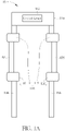
- FIG. 1A , 1B are respectively a schematic diagram and a functional block diagram of an exoskeleton system 10 according to an embodiment of the present invention.
- the exoskeleton system 10 used to assist human moving, comprises a trunk 100, branches 102, 104, 106, 108, a driving device 110, and a control device 112.
- the driving device 110 comprises motors 114, 116, 118 and 120, which are respectively connected to the branches 102, 104, 106 and 108, and the driving device 110 drives operations of the branches 102, 104, 106 and 108 to assist the user to walk or run according to a control signal CTRL generated by the control device 112.
- the control device 112 comprises a sensing unit 122 and a processing unit 124.
- the sensing unit 122 measures frontal topographic data of the exoskeleton system 10 in a moving direction thereof, and the processing unit 124 determines the frontal terrain, such as uphill, downhill, obstacles, etc. according to the measurement result of the sensing unit 122, to generate a control signal CTRL to drive driving device 110, for making exoskeleton system 10 to adjust the auxiliary force corresponding to the frontal terrain.
- control device 112 may measure the frontal topographic data or status in the moving direction of the exoskeleton system 10 worn by the user, and accordingly adjust the operation of the driving device 110. Therefore, if there are obstacles, uphill, downhill, stairs and other terrain changes in the moving direction of the user, the embodiment of the present invention automatically adjusts the operation of the driving device 110 without control commands manually inputted by the user, such that the relative movements among the branches 102, 104, 106 and 108 fit the follow-up terrain changes, so as to assist the user more efficiently and enhance convenience.
- FIG. 1A and FIG. 1B illustrate an embodiment of the present invention, and those skilled in the art may make modifications and alterations accordingly, and not limited herein.
- the sensing unit 122 may measure the frontal terrain data in various ways.
- the sensing unit 122 may measure a distance and direction of at least one target point corresponding to the sensing unit 122, and the processing unit 124 may execute geometric operations to determine contour coordinates of terrain changes and accordingly determine the corresponding frontal terrain.
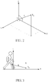
- FIG. 2 is a schematic diagram of measuring a distance and a direction of a target point R k by a three-axis measurement method according to an embodiment of the present invention. As shown in FIG.
- the sensing unit 122 measures a distance d k between the target point R k and the sensing unit 122, and the relationship between the target point R k and the sensing unit 122 may be mapped to a three-axis coordinate system, wherein the origin O is the sensing unit 122, and X-axis, Y-axis, and Z-axis represent the roll, pitch, and yaw respectively.
- the sensing unit 122 may be fixed on any position of the exoskeleton system 10 as long as the topographic data is correctly measured.
- the sensing unit 122 may comprise a plurality of sensing subunits; for example, one of the sensing subunits is located on the branch of the left lower leg, and another sensing subunit is located on the branch of the right lower leg.
- calculation of the distance and direction between the target point and the sensing unit 122 needs to be adjusted.
- FIG. 3 is a schematic diagram of the sensing unit 122 calculating a distance and a direction of a target point according to an embodiment of the present invention.
- the sensing unit 122 comprises two sensing subunits, one of the sensing subunits is disposed on the branch 104, and the other one is disposed on the branch 108.
- the sensing subunits of the sensing unit 122 may measure continuously distances d 0 to d n and angles a 0 to a n of the branch of the lower leg.
- the processing unit 124 may determine whether there exists a special frontal terrain in the moving direction according to the contour coordinates.
- FIG. 4A is a schematic diagram of the processing unit 124 determining the frontal terrain in the moving direction according to an embodiment of the present invention.
- the sensing unit 122 comprises two sensing subunits, the one is disposed on the branch 104, and the other one is deposed on the branch 108, wherein the frontal terrains comprise uphill. As shown in FIG.
- the sensing subunit of the sensing unit 122 located on the right lower leg measures a plurality of target points R 0 to R n .
- the index k of the target point increases, both of a k and d k decrease.
- the Y coordinate R k [Y] of the target point R k decreases as the X coordinates R k [X] decreases.
- the embodiment determines that the frontal terrain of the exoskeleton system 10 in the moving direction is an uphill terrain, and the processing unit 124 may accordingly generate a control signal CTRL to adjust the motor 116, to adjust the location of the next touchdown point corresponding to the branch 104 of the left lower leg.
- the bottom of the branch 108 corresponding to the right lower leg is the fulcrum. If the processing unit 124 determines that the frontal terrain is an uphill terrain according to the measurement result of the sensing unit 122, then comparing with the touchdown point of the flat terrain, the vertical distance of the next touchdown point of the branch 104 of the left lower leg is shorter. In this situation, the control device 112 may adjust the operation of the motor 116 via the control signal CTRL, to make the next touchdown point of the branch 104 of the left lower leg to fit the uphill terrain; that is, the next touchdown point is higher than the original (flat terrain) touchdown point to avoid improper auxiliary force and ensure that the user can walk smoothly.
- FIG. 4B to 4E are schematic diagrams of the processing unit 124 determining the frontal terrains in the moving direction according to an embodiment of the present invention.
- the sensing unit 122 measures a plurality of target points R 0 to R n
- the processing unit 124 determines that the Y coordinate R t [Y] of a target point R t within the target points R i to R 0 decreases as the X coordinates R t [X] increases.
- the embodiment determines that the frontal terrain of the exoskeleton system 10 in the moving direction is a downhill terrain, and the control device 112 may adjust the motor 116 via the control signal CTRL, to make a next touchdown point of branch 104 of the left lower leg to fit the download terrain; that is, the next touchdown point is lower than the original (flat terrain) touchdown point to avoid improper auxiliary force and ensure that the user can walk smoothly.
- the sensing unit 122 measures a plurality of target points R 0 to R n
- the processing unit 124 determines that the Y coordinate R t [Y] of a target point R t within the target points R i to R 0 is kept the same no matter how the X coordinate R t [X] changes. Therefore, the embodiment determines the frontal terrain of the exoskeleton system 10 in the moving direction is an flat terrain, and the control device 112 may adjust the motor 116 via the control signal CTRL, to make a next touchdown point of the branch 104 of the left lower leg to fit the flat terrain; that is, the next touchdown point is near to the original touchdown point to avoid improper auxiliary force and ensure that the user can walk smoothly.
- the sensing unit 122 measures a plurality of target points R 0 to R n
- the processing unit 124 determines that the X coordinate R t [X] of a target point R t within the target points R i to R 0 is kept the same while the Y coordinate R t [Y] is different (for example, considering coordinates of a first target point R a and a second target point R b within the target points R i to R 0 , if the X coordinate R a [X] (the first value) of the first target point R a and the Y coordinate R a [Y] (the second value) are taken as basis, when the X coordinate R b [X] of the second target point R b is not greater than the first value R a [X], but the Y coordinate R b [Y] is greater than the second value (R a [Y])), the embodiment determines the frontal terrain of the exoskeleton system 10 in the moving direction is a bump. Meanwhile, the
- the processing unit 124 further determines that the Y coordinate R s [Y] of a target point R s within the target points R i to R 0 is kept the same no matter how the X coordinate R s [X] changes, which corresponds to the flat terrain.
- the processing unit 124 may determine that the frontal terrain of the exoskeleton system 10 in the moving direction is an ascending stair, and the control device 112 may adjust the motor 116 via the control signal CTRL, to make a next touchdown point of branch 104 of the left lower leg to fit the ascending stair; that is, the next touchdown point is on the plate of the ascending stair to avoid improper auxiliary force and ensure that the user can walk smoothly.
- the sensing unit 122 measures a plurality of target points R 0 to R n
- the processing unit 124 determines that the Y coordinate R t [Y] of a target point R t within the target points R i to R 0 is kept the same no matter how the X coordinate R t [X] changes, and the Y coordinate R s [Y] of a target point R s within the target points R i to R 0 is kept the same no matter how the X coordinate R s [X] changes.
- the processing unit 124 may determine that the frontal terrain of the exoskeleton system 10 in the moving direction is a flat terrain, and the processing unit 124 may further determine that the frontal terrain of the exoskeleton system 10 in the moving direction is a descending stair according to R t [Y]>R s [Y].
- the control device 112 may adjust the motor 116 via the control signal CTRL, to make a next touchdown point of the branch 104 of the left lower leg to fit the descending stair; that is, the next touchdown point is on the plate of the descending stair to avoid improper auxiliary force and ensure that the user can walk smoothly.
- the processing unit 124 may determine that the frontal terrain of the exoskeleton system 10 in the moving direction is an uphill, downhill, flat, bump, ascending stair, and descending stair terrain, and accordingly adjust the driving device 110. For example, when the user walks naturally and lifts his/her left leg, the bottom of the branch 108 corresponding to the right lower leg is the fulcrum, the processing unit 124 determines the frontal terrain is an uphill, downhill, flat, bump, ascending stair, and descending stair, and adjusts the driving device 110 to make a next touchdown point of branch 104 of the left lower leg to fit the terrain.
- the processing unit 124 determines that the frontal terrain is a bump, and if the bump does not hinder walking, then the processing unit 124 adjusts the driving device 110 to make the bottom of branch cross the bump; if the horizontal position of the bump is the same as the original step, then the processing unit 124 adjusts the driving device 110 to make the bottom of branch to be on the bump; or, if the vertical height of the bump is too large to cross, then the processing unit 124 adjusts the driving device 110 to make the exoskeleton system 10 to bypass the bump, shows a warning message to the user, or stops walking.
- the exoskeleton system 10 may adjust the auxiliary force corresponding to the frontal terrain by measuring the frontal terrain in the moving direction, and ensure that the user can walk smoothly without the user's indication.
- FIG. 3 and FIG. 4A to 4E illustrate the terrain determining method of the processing unit 124 in the condition that the sensing unit 122 comprises two sensing subunits, which are disposed on the branches of the left lower leg and the right lower leg respectively, the processing unit 124.
- the sensing unit 122 may be disposed on any location according to different system requirements.
- FIG. 5 is a schematic diagram of the sensing unit 122 measuring a distance and a direction of a target point according to an embodiment of the present invention.
- the rest details of determining the terrain according to the coordinates of the target points may be referred to the above, which are not narrated herein for brevity.
- the sensing unit 122 may be implemented by a plurality of sensing subunits, and the sensing subunits may not limit to be disposed on the waist or legs.
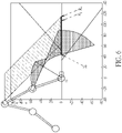
- FIG. 6 is a schematic diagram of the sensing unit 122 comprising two sensing subunits disposed at locations corresponding to user's waist and leg in the exoskeleton system 10 according to an embodiment of the present invention.
- the two sensing subunits of the sensing unit 122 are disposed on the user's waist and leg respectively to measure the target points from different heights, the determining results of the processing unit 124 are more precisely to fit the practical terrain, to enhance efficiency.
- sensing subunits may increase the sensing range and make the sensing results more accurate.
- methods of determining the frontal terrain of the exoskeleton system 10 for each of the sensing subunits are similar to those of the single sensing unit, which are not narrated herein for brevity.
- the frontal terrain may be further classified.
- the uphill terrain may be further classified into extremely gentle slopes with a slope of 5°, gentle slopes with a slope of 5°-15 °, gentle steep slopes with a slope of 15°-25°, steep slopes with a slope of 25°-35°, and not limited herein.
- the control device 112 may adjust the driving device 110 according to different terrains and the requirements by the user.
- the exoskeleton system 10 may comprise an input device, which provides the user to adjust the corresponding relation between the terrains and the driving device 110 or to limit the moving direction to the exoskeleton system 10. For example, if the exoskeleton system 10 encounters an uphill terrain with a slope more than 30°, then the exoskeleton system 10 will bypass the uphill terrain instead of climbing the uphill terrain, and not limited herein.
- each branch may further comprise sub-branches, wherein each (sub-)branch may comprise any number of sub-driving devices and sub-control devices, to adjust a partial or whole of the branch for the more detailed local actions according to different frontal terrains.
- the driving device 110 is not limited to be implemented by motors, and may be a pneumatic or hydraulic device.
- control device 112 may control the driving device 110 directly via an interface or indirectly via an inter-process communication, and the control device 112 may transmit only the measurement results of the frontal terrain measured by the sensing unit 122 in the moving direction, which may be adjusted by a sub-processing unit of the driving device 110.
- the control methods of the driving device 110 are well-known to those skilled in the art, which are not narrated herein for brevity.
- the sensing unit 122 may use optical, laser, radio, or ultrasonic methods to actively or passively sense terrain data.
- the sensing unit 122 may also be implemented by three-axis, six-axis, or nine-axis sensors, and may can transmit data to the processing unit 124 via a wire or wirelessly.
- each unit may be implemented by an application-specific integrated circuit (ASIC).
- the processing unit 124 may comprise a processor and a storage unit.
- the processor may be a processing unit, an application processor (AP) or a digital signal processor (DSP), wherein the processing unit may be a central processing unit (CPU), a graphics processing unit (GPU) or a tensor processing unit (TPU), and not limited thereto.
- the storage unit may be a memory, which may be a non-volatile memory, such as an electrically erasable programmable read-only memory (EEPROM) or a flash memory, and not limited thereto.
- EEPROM electrically erasable programmable read
- control device 112 may start to perform the control process for determining the frontal terrain in the moving direction only when detecting new step.
- a step sensor may be configured to save the power consumption or reduce the interference to the exoskeleton system 10 when the user walks, to avoid discomfort to the user.
- the method of configuring the step sensor is known to those skilled in the art, which is not narrated herein for brevity.
- control process 70 comprises the following step:
- control process 70 The detailed operation of the control process 70 may be referred to the foregoing description, which is not narrated herein for brevity.
- the exoskeleton system of the present invention measures the frontal terrain in the moving direction and adjusts the auxiliary force corresponding to the frontal terrain without the indication of the user. Therefore, the present invention can effectively improve the convenience of use and the smoothness of movement.
Landscapes
- Engineering & Computer Science (AREA)
- Robotics (AREA)
- Mechanical Engineering (AREA)
- Health & Medical Sciences (AREA)
- Epidemiology (AREA)
- Pain & Pain Management (AREA)
- Physical Education & Sports Medicine (AREA)
- Rehabilitation Therapy (AREA)
- Life Sciences & Earth Sciences (AREA)
- Animal Behavior & Ethology (AREA)
- General Health & Medical Sciences (AREA)
- Public Health (AREA)
- Veterinary Medicine (AREA)
- Rehabilitation Tools (AREA)
- Prostheses (AREA)
- Control Of Multiple Motors (AREA)
Description
- The present invention relates to an exoskeleton system, a control device and a control method, and more particularly, to an exoskeleton system, a control device and a control method capable of self-adjusting according to the frontal terrain.
- Exoskeleton robots assist people having mobility problems or enhance users' mobility, such as walking, stair climbing, slope climbing, and other applications.
US 2011/0066088 A1 (D1) discloses a control device applied to an exoskeleton system, andJP 2002144278 A - Generally speaking, a conventional control method of an exoskeleton robot is to input control commands (such as walking or going up and down along a slope or ramp) by the user with buttons or panels; however, the exoskeleton robot must be programmed in advance for its step distance, slope, and stair height in this method. Hence, the conventional exoskeleton robots are often obstructed due to the variance of the slope and stair height, which makes the user kick the uphill terrain and ascending stair, or makes the user lose balance because of the variance of the angel and stair height for the downhill terrain and descending stair. Under such circumstances, the conventional exoskeleton robots are inconvenient to operate, and may cause discomfort to the user due to improper movements, or even cause safety problems.
- Therefore, it is necessary to improve the prior art.
- It is therefore a primary objective of the present invention to provide an exoskeleton system, a control device and a control method, to improve over disadvantages of the prior art.
- This is achieved by a control device, applied to an exoskeleton system, according to the independent claims 1, 8 and 15 here below. The dependent claims pertain to corresponding further developments and improvements.
- As will be seen more clearly from the detailed description following below, a control device, applied to an exoskeleton system, comprises a sensing unit, configured to measure topographic data; and a processing unit, coupled to the sensing unit, configured to determine a frontal terrain of the exoskeleton system in a moving direction according to a measurement of the sensing unit to adjust an operation of a driving device of the exoskeleton system; wherein the sensing unit is configured to measure a distance and a direction of at least one measuring point corresponding to the sensing unit to measure the topographic data, wherein the at least one measuring point is located in front of the exoskeleton system in the moving direction.
- In another aspect, an exoskeleton system comprises at least one branch; a driving device, connected to the at least one branch, configured to drive the at least one branch according to a control signal; and a control device, comprising: a sensing unit, configured to measure a topographic data; and a processing unit, coupled to the sensing unit and the driving device, configured to determine a frontal terrain of the exoskeleton system in a moving direction according to a measurement of the sensing unit, to generate the control signal and to adjust an operation of a driving device; wherein the sensing unit is configured to measure a distance and a direction of at least one measuring point corresponding to the sensing unit to measure the topographic data, wherein the at least one measuring point is located in front of the exoskeleton system in the moving direction.
- In another aspect, a control method, applied to an exoskeleton system, comprises measuring a topographic data; and determining a frontal terrain of the exoskeleton system in a moving direction according to the topographic data, to adjust an operation of a driving device of the exoskeleton system; wherein the step for measuring the topographic data comprises a distance and a direction of at least one measuring point corresponding to the exoskeleton system, wherein the at least one measuring point is located in front of the exoskeleton system in the moving direction.
-
-
FIG. 1A is a schematic diagram of an exoskeleton system according to an embodiment of the present invention. -
FIG. 1B is a functional block diagram of the exoskeleton system according to an embodiment of the present invention. -
FIG. 2 is a schematic diagram of measuring a distance and a direction of a target point by a three-axis measuring method according to an embodiment of the present invention. -
FIG. 3 is a schematic diagram of calculating a distance and a direction of a target point according to an embodiment of the present invention. -
FIG. 4A to 4E are schematic diagrams of determining the frontal terrain in the moving direction according to an embodiment of the present invention. -
FIG. 5 is a schematic diagram of measuring a distance and a direction of a target point according to an embodiment of the present invention. -
FIG. 6 is a schematic diagram of measuring a distance and a direction of a target point according to an embodiment of the present invention. -
FIG. 7 is a schematic diagram of a control process according to an embodiment of the present invention. -
FIG. 1A ,1B are respectively a schematic diagram and a functional block diagram of anexoskeleton system 10 according to an embodiment of the present invention. Theexoskeleton system 10, used to assist human moving, comprises atrunk 100,branches driving device 110, and acontrol device 112. Thebranches trunk 100, and may be fixed to or worn on legs of a user; for example, thebranch 102 corresponds to the left upper leg, thebranch 104 corresponds to the left lower leg, thebranch 106 corresponds to the right upper leg, and thebranch 108 corresponds to the right lower leg. Thedriving device 110 comprisesmotors branches driving device 110 drives operations of thebranches control device 112. Thecontrol device 112 comprises asensing unit 122 and aprocessing unit 124. Thesensing unit 122 measures frontal topographic data of theexoskeleton system 10 in a moving direction thereof, and theprocessing unit 124 determines the frontal terrain, such as uphill, downhill, obstacles, etc. according to the measurement result of thesensing unit 122, to generate a control signal CTRL to drivedriving device 110, for makingexoskeleton system 10 to adjust the auxiliary force corresponding to the frontal terrain. - In brief, the
control device 112 may measure the frontal topographic data or status in the moving direction of theexoskeleton system 10 worn by the user, and accordingly adjust the operation of thedriving device 110. Therefore, if there are obstacles, uphill, downhill, stairs and other terrain changes in the moving direction of the user, the embodiment of the present invention automatically adjusts the operation of thedriving device 110 without control commands manually inputted by the user, such that the relative movements among thebranches - Notably,
FIG. 1A andFIG. 1B illustrate an embodiment of the present invention, and those skilled in the art may make modifications and alterations accordingly, and not limited herein. For example, thesensing unit 122 may measure the frontal terrain data in various ways. In an embodiment, thesensing unit 122 may measure a distance and direction of at least one target point corresponding to thesensing unit 122, and theprocessing unit 124 may execute geometric operations to determine contour coordinates of terrain changes and accordingly determine the corresponding frontal terrain. For example, please refer toFIG. 2 , which is a schematic diagram of measuring a distance and a direction of a target point Rk by a three-axis measurement method according to an embodiment of the present invention. As shown inFIG. 2 , in a measurement, thesensing unit 122 measures a distance dk between the target point Rk and thesensing unit 122, and the relationship between the target point Rk and thesensing unit 122 may be mapped to a three-axis coordinate system, wherein the origin O is thesensing unit 122, and X-axis, Y-axis, and Z-axis represent the roll, pitch, and yaw respectively. - In addition, the
sensing unit 122 may be fixed on any position of theexoskeleton system 10 as long as the topographic data is correctly measured. Thesensing unit 122 may comprise a plurality of sensing subunits; for example, one of the sensing subunits is located on the branch of the left lower leg, and another sensing subunit is located on the branch of the right lower leg. As the configuration or disposition of thesensing unit 122 changes, calculation of the distance and direction between the target point and thesensing unit 122 needs to be adjusted. For example, please refer toFIG. 3 , which is a schematic diagram of thesensing unit 122 calculating a distance and a direction of a target point according to an embodiment of the present invention. In the embodiment, thesensing unit 122 comprises two sensing subunits, one of the sensing subunits is disposed on thebranch 104, and the other one is disposed on thebranch 108. When the user walks naturally, the left (right) leg is a fulcrum, the sensing subunits of thesensing unit 122 may measure continuously distances d0 to dn and angles a0 to an of the branch of the lower leg. After the operation of theprocessing unit 124, the coordinates R0 to Rn corresponding to the obstacle contour based on the origin of theprocessing unit 124 are obtained. If the coordinate system is set with the fulcrum (i.e., the bottom of branch of the lower leg) as the origin, the coordinate x of k-th target point Rk is Rk[X]=L∗cos(ak)+dk ∗cos(ak+δ); the coordinate y is Rk[Y]=L∗sin(ak)+dk ∗sin(ak+δ), wherein 8 is the angle between thesensing unit 122 and the branch of the lower leg, and L is the length of the branch of the lower leg. - After obtaining the statistics of Rk[X], Rk[Y] mentioned above, the
processing unit 124 may determine whether there exists a special frontal terrain in the moving direction according to the contour coordinates. For example,FIG. 4A is a schematic diagram of theprocessing unit 124 determining the frontal terrain in the moving direction according to an embodiment of the present invention. In this example, thesensing unit 122 comprises two sensing subunits, the one is disposed on thebranch 104, and the other one is deposed on thebranch 108, wherein the frontal terrains comprise uphill. As shown inFIG. 4A , when the user walks naturally and lifts his/her left leg, the sensing subunit of thesensing unit 122 located on the right lower leg measures a plurality of target points R0 to Rn. As the index k of the target point increases, both of ak and dk decrease. As can be known by the geometric calculation, the Y coordinate Rk[Y] of the target point Rk decreases as the X coordinates Rk[X] decreases. Therefore, the embodiment determines that the frontal terrain of theexoskeleton system 10 in the moving direction is an uphill terrain, and theprocessing unit 124 may accordingly generate a control signal CTRL to adjust themotor 116, to adjust the location of the next touchdown point corresponding to thebranch 104 of the left lower leg. - Furthermore, when the user walks naturally and lifts his/her left leg, the bottom of the
branch 108 corresponding to the right lower leg is the fulcrum. If theprocessing unit 124 determines that the frontal terrain is an uphill terrain according to the measurement result of thesensing unit 122, then comparing with the touchdown point of the flat terrain, the vertical distance of the next touchdown point of thebranch 104 of the left lower leg is shorter. In this situation, thecontrol device 112 may adjust the operation of themotor 116 via the control signal CTRL, to make the next touchdown point of thebranch 104 of the left lower leg to fit the uphill terrain; that is, the next touchdown point is higher than the original (flat terrain) touchdown point to avoid improper auxiliary force and ensure that the user can walk smoothly. - Similar to
FIG. 4A , please continue to refer toFIG. 4B to 4E , which are schematic diagrams of theprocessing unit 124 determining the frontal terrains in the moving direction according to an embodiment of the present invention. InFIG. 4B , thesensing unit 122 measures a plurality of target points R0 to Rn, and theprocessing unit 124 determines that the Y coordinate Rt[Y] of a target point Rt within the target points Ri to R0 decreases as the X coordinates Rt[X] increases. Therefore, the embodiment determines that the frontal terrain of theexoskeleton system 10 in the moving direction is a downhill terrain, and thecontrol device 112 may adjust themotor 116 via the control signal CTRL, to make a next touchdown point ofbranch 104 of the left lower leg to fit the download terrain; that is, the next touchdown point is lower than the original (flat terrain) touchdown point to avoid improper auxiliary force and ensure that the user can walk smoothly. - In
FIG. 4C , thesensing unit 122 measures a plurality of target points R0 to Rn, and theprocessing unit 124 determines that the Y coordinate Rt[Y] of a target point Rt within the target points Ri to R0 is kept the same no matter how the X coordinate Rt[X] changes. Therefore, the embodiment determines the frontal terrain of theexoskeleton system 10 in the moving direction is an flat terrain, and thecontrol device 112 may adjust themotor 116 via the control signal CTRL, to make a next touchdown point of thebranch 104 of the left lower leg to fit the flat terrain; that is, the next touchdown point is near to the original touchdown point to avoid improper auxiliary force and ensure that the user can walk smoothly. - In
FIG. 4D , thesensing unit 122 measures a plurality of target points R0 to Rn, and theprocessing unit 124 determines that the X coordinate Rt[X] of a target point Rt within the target points Ri to R0 is kept the same while the Y coordinate Rt[Y] is different (for example, considering coordinates of a first target point Ra and a second target point Rb within the target points Ri to R0, if the X coordinate Ra[X] (the first value) of the first target point Ra and the Y coordinate Ra[Y] (the second value) are taken as basis, when the X coordinate Rb[X] of the second target point Rb is not greater than the first value Ra[X], but the Y coordinate Rb[Y] is greater than the second value (Ra[Y])), the embodiment determines the frontal terrain of theexoskeleton system 10 in the moving direction is a bump. Meanwhile, theprocessing unit 124 may determine the size of the bump according to other target points (such as Rc, Rd ...) within the target points Ri to R0. - Next, the
processing unit 124 further determines that the Y coordinate Rs[Y] of a target point Rs within the target points Ri to R0 is kept the same no matter how the X coordinate Rs[X] changes, which corresponds to the flat terrain. Therefore, combining the determining results of the target points Rt and Rs, theprocessing unit 124 may determine that the frontal terrain of theexoskeleton system 10 in the moving direction is an ascending stair, and thecontrol device 112 may adjust themotor 116 via the control signal CTRL, to make a next touchdown point ofbranch 104 of the left lower leg to fit the ascending stair; that is, the next touchdown point is on the plate of the ascending stair to avoid improper auxiliary force and ensure that the user can walk smoothly. - In
FIG. 4E , thesensing unit 122 measures a plurality of target points R0 to Rn, and theprocessing unit 124 determines that the Y coordinate Rt[Y] of a target point Rt within the target points Ri to R0 is kept the same no matter how the X coordinate Rt[X] changes, and the Y coordinate Rs[Y] of a target point Rs within the target points Ri to R0 is kept the same no matter how the X coordinate Rs[X] changes. Theprocessing unit 124 may determine that the frontal terrain of theexoskeleton system 10 in the moving direction is a flat terrain, and theprocessing unit 124 may further determine that the frontal terrain of theexoskeleton system 10 in the moving direction is a descending stair according to Rt[Y]>Rs[Y]. Thus, thecontrol device 112 may adjust themotor 116 via the control signal CTRL, to make a next touchdown point of thebranch 104 of the left lower leg to fit the descending stair; that is, the next touchdown point is on the plate of the descending stair to avoid improper auxiliary force and ensure that the user can walk smoothly. - Therefore, via the determining methods shown in
FIG. 4A to 4E , theprocessing unit 124 may determine that the frontal terrain of theexoskeleton system 10 in the moving direction is an uphill, downhill, flat, bump, ascending stair, and descending stair terrain, and accordingly adjust thedriving device 110. For example, when the user walks naturally and lifts his/her left leg, the bottom of thebranch 108 corresponding to the right lower leg is the fulcrum, theprocessing unit 124 determines the frontal terrain is an uphill, downhill, flat, bump, ascending stair, and descending stair, and adjusts thedriving device 110 to make a next touchdown point ofbranch 104 of the left lower leg to fit the terrain. When theprocessing unit 124 determines that the frontal terrain is a bump, and if the bump does not hinder walking, then theprocessing unit 124 adjusts thedriving device 110 to make the bottom of branch cross the bump; if the horizontal position of the bump is the same as the original step, then theprocessing unit 124 adjusts thedriving device 110 to make the bottom of branch to be on the bump; or, if the vertical height of the bump is too large to cross, then theprocessing unit 124 adjusts thedriving device 110 to make theexoskeleton system 10 to bypass the bump, shows a warning message to the user, or stops walking. In this way, theexoskeleton system 10 may adjust the auxiliary force corresponding to the frontal terrain by measuring the frontal terrain in the moving direction, and ensure that the user can walk smoothly without the user's indication. - Notably,
FIG. 3 andFIG. 4A to 4E illustrate the terrain determining method of theprocessing unit 124 in the condition that thesensing unit 122 comprises two sensing subunits, which are disposed on the branches of the left lower leg and the right lower leg respectively, theprocessing unit 124. However, not limited herein, thesensing unit 122 may be disposed on any location according to different system requirements. For example, please refer toFIG. 5 , which is a schematic diagram of thesensing unit 122 measuring a distance and a direction of a target point according to an embodiment of the present invention. In this example, because thesensing unit 122 is disposed on the user's waist, the geometric operation implemented by theprocessing unit 124 corresponding to the target point Rk should be adjusted as follows: the coordinate X is Rk[X]=L∗cos(90°)+dk ∗cos(90°+δ), and the coordinate Y is Rk[Y]=L∗sin(90o)+dk ∗sin(90°+δ), wherein δ is the angel between thesensing unit 122 and the user's waist, and L is the height of the location on which thesensing unit 122 is disposed. The rest details of determining the terrain according to the coordinates of the target points may be referred to the above, which are not narrated herein for brevity. - In addition, as mentioned above, the
sensing unit 122 may be implemented by a plurality of sensing subunits, and the sensing subunits may not limit to be disposed on the waist or legs. For example, please refer toFIG. 6 , which is a schematic diagram of thesensing unit 122 comprising two sensing subunits disposed at locations corresponding to user's waist and leg in theexoskeleton system 10 according to an embodiment of the present invention. As shown inFIG. 6 , because the two sensing subunits of thesensing unit 122 are disposed on the user's waist and leg respectively to measure the target points from different heights, the determining results of theprocessing unit 124 are more precisely to fit the practical terrain, to enhance efficiency. Notably, increasing the number of sensing subunits may increase the sensing range and make the sensing results more accurate. And the methods of determining the frontal terrain of theexoskeleton system 10 for each of the sensing subunits are similar to those of the single sensing unit, which are not narrated herein for brevity. - In addition, in an embodiment of the present invention, the frontal terrain may be further classified. For example, the uphill terrain may be further classified into extremely gentle slopes with a slope of 5°, gentle slopes with a slope of 5°-15 °, gentle steep slopes with a slope of 15°-25°, steep slopes with a slope of 25°-35°, and not limited herein. The
control device 112 may adjust thedriving device 110 according to different terrains and the requirements by the user. - Furthermore, in an embodiment, the
exoskeleton system 10 may comprise an input device, which provides the user to adjust the corresponding relation between the terrains and thedriving device 110 or to limit the moving direction to theexoskeleton system 10. For example, if theexoskeleton system 10 encounters an uphill terrain with a slope more than 30°, then theexoskeleton system 10 will bypass the uphill terrain instead of climbing the uphill terrain, and not limited herein. - On the other hand, the
trunk 100 and thebranches device 110 is not limited to be implemented by motors, and may be a pneumatic or hydraulic device. In an embodiment, thecontrol device 112 may control thedriving device 110 directly via an interface or indirectly via an inter-process communication, and thecontrol device 112 may transmit only the measurement results of the frontal terrain measured by thesensing unit 122 in the moving direction, which may be adjusted by a sub-processing unit of thedriving device 110. The control methods of thedriving device 110 are well-known to those skilled in the art, which are not narrated herein for brevity. - In an embodiment, the
sensing unit 122 may use optical, laser, radio, or ultrasonic methods to actively or passively sense terrain data. Thesensing unit 122 may also be implemented by three-axis, six-axis, or nine-axis sensors, and may can transmit data to theprocessing unit 124 via a wire or wirelessly. In an embodiment, each unit may be implemented by an application-specific integrated circuit (ASIC). In an embodiment, theprocessing unit 124 may comprise a processor and a storage unit. The processor may be a processing unit, an application processor (AP) or a digital signal processor (DSP), wherein the processing unit may be a central processing unit (CPU), a graphics processing unit (GPU) or a tensor processing unit (TPU), and not limited thereto. The storage unit may be a memory, which may be a non-volatile memory, such as an electrically erasable programmable read-only memory (EEPROM) or a flash memory, and not limited thereto. - In an embodiment, the
control device 112 may start to perform the control process for determining the frontal terrain in the moving direction only when detecting new step. For example, a step sensor may be configured to save the power consumption or reduce the interference to theexoskeleton system 10 when the user walks, to avoid discomfort to the user. The method of configuring the step sensor is known to those skilled in the art, which is not narrated herein for brevity. - In addition, the operation of the
control device 112 may be summarized to a control process 70, as shown inFIG. 7 . The control process 70 comprises the following step: - Step 700: Start.
- Step 702: The sensing
unit 122 measures topographic data. - Step 704: According to the topographic data measured by the
sensing unit 122, theprocessing unit 124 determines the frontal terrain of theexoskeleton system 10 in the moving direction, to adjust the operation of thedriving device 110 of theexoskeleton system 10. - Step 706: End.
- The detailed operation of the control process 70 may be referred to the foregoing description, which is not narrated herein for brevity.
- Notably, the embodiments stated in the above are utilized for illustrating the concept of the present application. Those skilled in the art may make modifications and alterations accordingly, and not limited herein. Therefore, as long as the exoskeleton system may measure the frontal terrain in the moving direction and adjust the auxiliary force corresponding to the frontal terrain, the requirements of the present application are satisfied and within the scope of the present application.
- In summary, to assist the user to walk or run, the exoskeleton system of the present invention measures the frontal terrain in the moving direction and adjusts the auxiliary force corresponding to the frontal terrain without the indication of the user. Therefore, the present invention can effectively improve the convenience of use and the smoothness of movement.
Claims (15)
- A control device (112), applied to an exoskeleton system (10), comprising:a sensing unit (122), configured to measure topographic data; anda processing unit (124), coupled to the sensing unit (122), configured to determine a frontal terrain of the exoskeleton system (10) in a moving direction according to a measurement of the sensing unit (122) to adjust an operation of a driving device (110) of the exoskeleton system (10);wherein the sensing unit (122) is configured to measure a distance and a direction of at least one measuring point corresponding to the sensing unit (122) to measure the topographic data, wherein the at least one measuring point is located in front of the exoskeleton system (10) in the moving direction.
- An exoskeleton system (10), comprising:at least one branch (102, 104, 106, 108);a driving device (110), connected to the at least one branch (102, 104, 106, 108), configured to drive the at least one branch (102, 104, 106, 108) according to a control signal (CTRL); anda control device (112), comprising:a sensing unit (122), configured to measure a topographic data; anda processing unit (124), coupled to the sensing unit (122) and the driving device (110), configured to determine a frontal terrain of the exoskeleton system (10) in a moving direction according to a measurement of the sensing unit (122), to generate the control signal (CTRL) and to adjust an operation of a driving device (110);wherein the sensing unit (122) is configured to measure a distance and a direction of at least one measuring point corresponding to the sensing unit (122) to measure the topographic data, wherein the at least one measuring point is located in front of the exoskeleton system (10) in the moving direction.
- The control device (112) of claim 1 or the exoskeleton system (10) of claim 2, characterised in thatwhen the measurement of the sensing unit (122) shows that at least one vertical position of the at least one measuring point is higher than a current vertical position of a bottom of a branch of the exoskeleton system (10), the processing unit (124) determines that the frontal terrain in the moving direction of the exoskeleton system (10) is an uphill terrain; andthe processing unit (124) is further configured to calculate a grade and a vertical height of the uphill terrain to adjust the operation of the driving device (110) for making a next touchdown point of the bottom of the branch in the moving direction fit the height of the uphill terrain.
- The control device (112) of claim 1 or the exoskeleton system (10) of claim 2, characterised in thatwhen the measurement of the sensing unit (122) shows that at least one vertical position of the at least one measuring point is lower than a current vertical position of a bottom of a branch of the exoskeleton system (10), the processing unit (124) determines that the frontal terrain in the moving direction of the exoskeleton system (10) is a downhill terrain; andthe processing unit (124) is further configured to calculate a grade and a vertical height of the downhill terrain to adjust the operation of the driving device (110) for making a next touchdown point of the bottom of the branch in the moving direction fit the height of the downhill terrain.
- The control device (112) of claim 1 or the exoskeleton system (10) of claim 2, characterised in thatwhen the measurement of the sensing unit (122) shows that at least one vertical position of the at least one measuring point is similar to a current vertical position of a bottom of a branch of the exoskeleton system (10), the processing unit (124) determines that the frontal terrain in the moving direction of the exoskeleton system (10) is a flat terrain; andthe processing unit (124) is further configured to adjust the operation of the driving device (110) for making a next touchdown point of the bottom of the branch in the moving direction fit the flat terrain.
- The control device (112) of claim 1 or the exoskeleton system (10) of claim 2, characterised in thatwhen the measurement of the sensing unit (122) shows that a horizontal distance between the at least one measuring point and a bottom of a branch of the exoskeleton system (10) is not greater a first value, but a vertical distance between the measuring point and the bottom is greater than a second value, the processing unit (124) determines that the frontal terrain in the moving direction of the exoskeleton system (10) is a bump; andthe processing unit (124) is further configured to calculate a size of the bump to adjust the operation of the driving device (110) for making the bottom of the branch in the moving direction cross, fall upon, or bypass the bump or stop moving.
- The control device (112) of claim 1 or the exoskeleton system (10) of claim 2, characterised in thatwhen the measurement of the sensing unit (122) shows that the at least one measuring point is roughly located to a plane, and a vertical position is higher than a current vertical position of a bottom of a branch of the exoskeleton system (10), the processing unit (124) determines that the frontal terrain in the moving direction of the exoskeleton system (10) is an ascending stair; andthe processing unit (124) is further configured to calculate a step height of the ascending stair to adjust the operation of the driving device (110) for making a next touchdown point of the bottom of the branch in the moving direction fit the ascending stair.
- The control device (112) of claim 1 or the exoskeleton system (10) of claim 2, characterised in thatwhen the measurement of the sensing unit (122) shows that the at least one measuring point is roughly located to a plane, and a vertical position is lower than a current vertical position of a bottom of a branch of the exoskeleton system (10), the processing unit (124) determines that the frontal terrain in the moving direction of the exoskeleton system (10) is a descending stair; andthe processing unit (124) is further configured to calculate a step height of the descending stair to adjust the operation of the driving device (110) for making a next touchdown point of the bottom of the branch in the moving direction fit the descending stair.
- A control method (70), applied to an exoskeleton system (10), comprising:measuring a topographic data (702); anddetermining a frontal terrain of the exoskeleton system (10) in a moving direction according to the topographic data, to adjust an operation of a driving device (110) of the exoskeleton system (10) (704);wherein the step for measuring the topographic data (702) comprises a distance and a direction of at least one measuring point corresponding to the exoskeleton system (10), wherein the at least one measuring point is located in front of the exoskeleton system (10) in the moving direction.
- The control method (70) of claim 9, characterised by further comprising:when at least one vertical position of the at least one measuring point is higher than a current vertical position of a bottom of a branch of the exoskeleton system (10), determining that the frontal terrain in the moving direction of the exoskeleton system (10) is an uphill terrain; andcalculating a grade and a vertical height of the uphill terrain and adjusting the operation of the driving device (110) to make a next touchdown point of the bottom of the branch in the moving direction fit the height of the uphill terrain.
- The control method (70) of claim 9, characterised by further comprising:when at least one vertical position of the at least one measuring point is lower than a current vertical position of a bottom of a branch of the exoskeleton system (10), determining that the frontal terrain in the moving direction of the exoskeleton system (10) is a downhill terrain; andcalculating a grade and a vertical height of the downhill terrain and adjusting the operation of the driving device (110) to make a next touchdown point of the bottom of the branch in the moving direction fit the height of the downhill terrain.
- The control method (70) of claim 9, characterised by further comprising:when at least one vertical position of the at least one measuring point is similar to a current vertical position of a bottom of a branch of the exoskeleton system (10), determining that the frontal terrain in the moving direction of the exoskeleton system (10) is a flat terrain; andadjusting the operation of the driving device (110) to make a next touchdown point of the bottom of the branch in the moving direction fit the flat terrain.
- The control method (70) of claim 9, characterised by further comprising:when a horizontal distance between the at least one measuring point and a bottom of a branch of the exoskeleton system (10) is not greater a first value, but a vertical distance between the measuring point and the bottom is greater than a second value, determining that the frontal terrain in the moving direction of the exoskeleton system (10) is a bump; andcalculating a size of the bump and adjusting the operation of the driving device (110) to make the bottom of the branch in the moving direction cross, fall upon, or bypass the bump or stop moving.
- The control method (70) of claim 9, characterised by further comprising:when the at least one measuring point is roughly located to a plane, and a vertical position is higher than a current vertical position of a bottom of a branch of the exoskeleton system (10), determining that the frontal terrain in the moving direction of the exoskeleton system (10) is an ascending stair; andcalculating a step height of the ascending stair and adjusting the operation of the driving device (110) to make a next touchdown point of the bottom of the branch in the moving direction fit the ascending stair.
- The control method (70) of claim 9, characterised by further comprising:when the at least one measuring point is roughly located to a plane, and a vertical position is lower than a current vertical position of a bottom of a branch of the exoskeleton system (10), determining that the frontal terrain in the moving direction of the exoskeleton system (10) is a descending stair; andcalculating a step height of the descending stair and adjusting the operation of the driving device (110) to make a next touchdown point of the bottom of the branch in the moving direction fit the descending stair.
Applications Claiming Priority (1)
| Application Number | Priority Date | Filing Date | Title |
|---|---|---|---|
| TW108144735A TWI773947B (en) | 2019-12-06 | 2019-12-06 | Control device, exoskeleton system and control method |
Publications (2)
| Publication Number | Publication Date |
|---|---|
| EP3831541A1 EP3831541A1 (en) | 2021-06-09 |
| EP3831541B1 true EP3831541B1 (en) | 2022-06-15 |
Family
ID=69960563
Family Applications (1)
| Application Number | Title | Priority Date | Filing Date |
|---|---|---|---|
| EP20165492.8A Active EP3831541B1 (en) | 2019-12-06 | 2020-03-25 | Exoskeleton system, control device and control method |
Country Status (4)
| Country | Link |
|---|---|
| US (1) | US20210170572A1 (en) |
| EP (1) | EP3831541B1 (en) |
| CN (1) | CN112917471B (en) |
| TW (1) | TWI773947B (en) |
Families Citing this family (4)
| Publication number | Priority date | Publication date | Assignee | Title |
|---|---|---|---|---|
| US11853034B2 (en) | 2020-05-08 | 2023-12-26 | Skip Innovations, Inc. | Exosuit activity transition control |
| CN113547539A (en) * | 2021-07-30 | 2021-10-26 | 深圳市优必选科技股份有限公司 | Gimbals, Leg Structures, and Humanoid Robots |
| WO2025111601A1 (en) * | 2023-11-23 | 2025-05-30 | The Regents Of The University Of Michigan | Powered lower limb assistive device with obstacle avoidance |
| CN120735044B (en) * | 2025-08-29 | 2025-11-11 | 浙江工业大学 | Upper limb exoskeleton control method |
Family Cites Families (20)
| Publication number | Priority date | Publication date | Assignee | Title |
|---|---|---|---|---|
| JP4476468B2 (en) * | 2000-11-13 | 2010-06-09 | 本田技研工業株式会社 | Legged mobile robot |
| JP4178187B2 (en) * | 2005-01-26 | 2008-11-12 | 国立大学法人 筑波大学 | Wearable motion assist device and control program |
| US10080672B2 (en) * | 2005-03-31 | 2018-09-25 | Bionx Medical Technologies, Inc. | Hybrid terrain-adaptive lower-extremity systems |
| AU2008341232B2 (en) * | 2007-12-26 | 2015-04-23 | Rex Bionics Limited | Mobility aid |
| EP3219295B1 (en) * | 2008-09-04 | 2023-11-15 | Otto Bock HealthCare LP | Hybrid terrain-adaptive lower-extremity systems |
| EP2238894B1 (en) * | 2009-04-07 | 2011-11-02 | Syco Di Hedvig Haberl & C. S.A.S. | System for controlling an exoskeleton haptic device for rehabilitation purposes, and corresponding exoskeleton haptic device |
| KR101709605B1 (en) * | 2009-07-01 | 2017-02-23 | 렉스 바이오닉스 리미티드 | Control system for a mobility aid |
| CN103153234B (en) * | 2010-10-06 | 2016-09-14 | 艾克索仿生技术公司 | Man-machine interface for lower limb orthosis |
| US9687377B2 (en) * | 2011-01-21 | 2017-06-27 | Bionx Medical Technologies, Inc. | Terrain adaptive powered joint orthosis |
| US9675512B2 (en) * | 2013-03-14 | 2017-06-13 | Elwha Llc | Leg locomotion devices |
| KR102172954B1 (en) * | 2013-11-08 | 2020-11-02 | 삼성전자주식회사 | A walk-assistive robot and a method for controlling the walk-assistive robot |
| WO2015143157A1 (en) * | 2014-03-21 | 2015-09-24 | Ekso Bionics, Inc. | Ambulatory exoskeleton and method of relocating exoskeleton |
| CN104013513B (en) * | 2014-06-05 | 2016-08-17 | 电子科技大学 | Healing robot sensory perceptual system and method thereof |
| DE102015107783A1 (en) * | 2015-05-18 | 2016-11-24 | Inventus Engineering Gmbh | Prosthetic or exoskeletal component, prosthetic or exoskeleton and method |
| US20180296426A1 (en) * | 2015-10-16 | 2018-10-18 | Rewalk Robotics Ltd. | Apparatuses, systems and methods for controlling exoskeletons |
| FR3061653B1 (en) * | 2017-01-10 | 2019-05-31 | Wandercraft | METHOD FOR SETTING UP AN EXOSQUELET |
| CN109132392A (en) * | 2017-06-27 | 2019-01-04 | 广西大学 | A kind of AGV forklift ramp recognition methods |
| TWM555539U (en) * | 2017-08-10 | 2018-02-11 | 城市學校財團法人臺北城市科技大學 | Safety reminding device |
| IL272623B2 (en) * | 2017-08-29 | 2024-12-01 | Roam Robotics Inc | System and method for detecting semi-guided intent |
| US10624809B2 (en) * | 2017-11-09 | 2020-04-21 | Free Bionics Taiwan Inc. | Exoskeleton robot and controlling method for exoskeleton robot |
-
2019
- 2019-12-06 TW TW108144735A patent/TWI773947B/en active
- 2019-12-27 CN CN201911373232.0A patent/CN112917471B/en active Active
-
2020
- 2020-02-25 US US16/799,838 patent/US20210170572A1/en not_active Abandoned
- 2020-03-25 EP EP20165492.8A patent/EP3831541B1/en active Active
Also Published As
| Publication number | Publication date |
|---|---|
| EP3831541A1 (en) | 2021-06-09 |
| US20210170572A1 (en) | 2021-06-10 |
| CN112917471B (en) | 2022-05-24 |
| CN112917471A (en) | 2021-06-08 |
| TWI773947B (en) | 2022-08-11 |
| TW202123256A (en) | 2021-06-16 |
Similar Documents
| Publication | Publication Date | Title |
|---|---|---|
| US12365407B2 (en) | Mechanically-timed footsteps for a robotic device | |
| EP3831541A1 (en) | Exoskeleton system, control device and control method | |
| US20250153361A1 (en) | Handling gait disturbances with asynchronous timing | |
| US20250135646A1 (en) | Robotically negotiating stairs | |
| US11188081B2 (en) | Auto-swing height adjustment | |
| US9969087B1 (en) | Leg collision avoidance in a robotic device | |
| US20230415343A1 (en) | Automatically trasitioning a robot to an operational mode optimized for particular terrain | |
| US9663165B1 (en) | Slip avoidance | |
| US20190176329A1 (en) | Determination of Robotic Step Path | |
| US20130116820A1 (en) | Walking robot and control method thereof | |
| US6980919B2 (en) | Walking condition determining device and method | |
| US10179619B1 (en) | Robotic foot sensor | |
| CN115344040A (en) | Method and device for planning foot end track of foot type robot and foot type robot | |
| CN117270551A (en) | Method and system for autonomous stair climbing by a quadruped robot based on local environment perception | |
| JP4295947B2 (en) | Legged mobile robot and its movement control method | |
| CN114633826A (en) | Leg collision processing method for foot type robot and foot type robot | |
| TWI422824B (en) | Human motion identification and locating method | |
| JP2001353686A (en) | Foot structure for legged mobile robot and road surface detection device | |
| JP2003025260A (en) | Walking control device for legged robot | |
| US12594669B2 (en) | Robot control method, robot control system, and computer readable medium | |
| JP4696728B2 (en) | Legged robot and its control method | |
| KR102896524B1 (en) | Gait assistance device for estimating gait parameters and operating method thereof | |
| JP2025536069A (en) | Multi-legged robot and its touchdown positioning method | |
| JP2007007801A (en) | Legged robot and its control method |
Legal Events
| Date | Code | Title | Description |
|---|---|---|---|
| STAA | Information on the status of an ep patent application or granted ep patent |
Free format text: STATUS: EXAMINATION IS IN PROGRESS |
|
| PUAI | Public reference made under article 153(3) epc to a published international application that has entered the european phase |
Free format text: ORIGINAL CODE: 0009012 |
|
| 17P | Request for examination filed |
Effective date: 20200325 |
|
| AK | Designated contracting states |
Kind code of ref document: A1 Designated state(s): AL AT BE BG CH CY CZ DE DK EE ES FI FR GB GR HR HU IE IS IT LI LT LU LV MC MK MT NL NO PL PT RO RS SE SI SK SM TR |
|
| GRAP | Despatch of communication of intention to grant a patent |
Free format text: ORIGINAL CODE: EPIDOSNIGR1 |
|
| STAA | Information on the status of an ep patent application or granted ep patent |
Free format text: STATUS: GRANT OF PATENT IS INTENDED |
|
| INTG | Intention to grant announced |
Effective date: 20220325 |
|
| GRAS | Grant fee paid |
Free format text: ORIGINAL CODE: EPIDOSNIGR3 |
|
| GRAA | (expected) grant |
Free format text: ORIGINAL CODE: 0009210 |
|
| STAA | Information on the status of an ep patent application or granted ep patent |
Free format text: STATUS: THE PATENT HAS BEEN GRANTED |
|
| AK | Designated contracting states |
Kind code of ref document: B1 Designated state(s): AL AT BE BG CH CY CZ DE DK EE ES FI FR GB GR HR HU IE IS IT LI LT LU LV MC MK MT NL NO PL PT RO RS SE SI SK SM TR |
|
| REG | Reference to a national code |
Ref country code: CH Ref legal event code: EP Ref country code: GB Ref legal event code: FG4D |
|
| REG | Reference to a national code |
Ref country code: IE Ref legal event code: FG4D |
|
| REG | Reference to a national code |
Ref country code: DE Ref legal event code: R096 Ref document number: 602020003517 Country of ref document: DE |
|
| REG | Reference to a national code |
Ref country code: AT Ref legal event code: REF Ref document number: 1498076 Country of ref document: AT Kind code of ref document: T Effective date: 20220715 |
|
| REG | Reference to a national code |
Ref country code: LT Ref legal event code: MG9D |
|
| REG | Reference to a national code |
Ref country code: NL Ref legal event code: MP Effective date: 20220615 |
|
| PG25 | Lapsed in a contracting state [announced via postgrant information from national office to epo] |
Ref country code: SE Free format text: LAPSE BECAUSE OF FAILURE TO SUBMIT A TRANSLATION OF THE DESCRIPTION OR TO PAY THE FEE WITHIN THE PRESCRIBED TIME-LIMIT Effective date: 20220615 Ref country code: NO Free format text: LAPSE BECAUSE OF FAILURE TO SUBMIT A TRANSLATION OF THE DESCRIPTION OR TO PAY THE FEE WITHIN THE PRESCRIBED TIME-LIMIT Effective date: 20220915 Ref country code: LT Free format text: LAPSE BECAUSE OF FAILURE TO SUBMIT A TRANSLATION OF THE DESCRIPTION OR TO PAY THE FEE WITHIN THE PRESCRIBED TIME-LIMIT Effective date: 20220615 Ref country code: HR Free format text: LAPSE BECAUSE OF FAILURE TO SUBMIT A TRANSLATION OF THE DESCRIPTION OR TO PAY THE FEE WITHIN THE PRESCRIBED TIME-LIMIT Effective date: 20220615 Ref country code: GR Free format text: LAPSE BECAUSE OF FAILURE TO SUBMIT A TRANSLATION OF THE DESCRIPTION OR TO PAY THE FEE WITHIN THE PRESCRIBED TIME-LIMIT Effective date: 20220916 Ref country code: FI Free format text: LAPSE BECAUSE OF FAILURE TO SUBMIT A TRANSLATION OF THE DESCRIPTION OR TO PAY THE FEE WITHIN THE PRESCRIBED TIME-LIMIT Effective date: 20220615 Ref country code: BG Free format text: LAPSE BECAUSE OF FAILURE TO SUBMIT A TRANSLATION OF THE DESCRIPTION OR TO PAY THE FEE WITHIN THE PRESCRIBED TIME-LIMIT Effective date: 20220915 |
|
| REG | Reference to a national code |
Ref country code: AT Ref legal event code: MK05 Ref document number: 1498076 Country of ref document: AT Kind code of ref document: T Effective date: 20220615 |
|
| PG25 | Lapsed in a contracting state [announced via postgrant information from national office to epo] |
Ref country code: RS Free format text: LAPSE BECAUSE OF FAILURE TO SUBMIT A TRANSLATION OF THE DESCRIPTION OR TO PAY THE FEE WITHIN THE PRESCRIBED TIME-LIMIT Effective date: 20220615 Ref country code: LV Free format text: LAPSE BECAUSE OF FAILURE TO SUBMIT A TRANSLATION OF THE DESCRIPTION OR TO PAY THE FEE WITHIN THE PRESCRIBED TIME-LIMIT Effective date: 20220615 |
|
| PG25 | Lapsed in a contracting state [announced via postgrant information from national office to epo] |
Ref country code: NL Free format text: LAPSE BECAUSE OF FAILURE TO SUBMIT A TRANSLATION OF THE DESCRIPTION OR TO PAY THE FEE WITHIN THE PRESCRIBED TIME-LIMIT Effective date: 20220615 |
|
| PG25 | Lapsed in a contracting state [announced via postgrant information from national office to epo] |
Ref country code: SM Free format text: LAPSE BECAUSE OF FAILURE TO SUBMIT A TRANSLATION OF THE DESCRIPTION OR TO PAY THE FEE WITHIN THE PRESCRIBED TIME-LIMIT Effective date: 20220615 Ref country code: SK Free format text: LAPSE BECAUSE OF FAILURE TO SUBMIT A TRANSLATION OF THE DESCRIPTION OR TO PAY THE FEE WITHIN THE PRESCRIBED TIME-LIMIT Effective date: 20220615 Ref country code: RO Free format text: LAPSE BECAUSE OF FAILURE TO SUBMIT A TRANSLATION OF THE DESCRIPTION OR TO PAY THE FEE WITHIN THE PRESCRIBED TIME-LIMIT Effective date: 20220615 Ref country code: PT Free format text: LAPSE BECAUSE OF FAILURE TO SUBMIT A TRANSLATION OF THE DESCRIPTION OR TO PAY THE FEE WITHIN THE PRESCRIBED TIME-LIMIT Effective date: 20221017 Ref country code: ES Free format text: LAPSE BECAUSE OF FAILURE TO SUBMIT A TRANSLATION OF THE DESCRIPTION OR TO PAY THE FEE WITHIN THE PRESCRIBED TIME-LIMIT Effective date: 20220615 Ref country code: EE Free format text: LAPSE BECAUSE OF FAILURE TO SUBMIT A TRANSLATION OF THE DESCRIPTION OR TO PAY THE FEE WITHIN THE PRESCRIBED TIME-LIMIT Effective date: 20220615 Ref country code: CZ Free format text: LAPSE BECAUSE OF FAILURE TO SUBMIT A TRANSLATION OF THE DESCRIPTION OR TO PAY THE FEE WITHIN THE PRESCRIBED TIME-LIMIT Effective date: 20220615 Ref country code: AT Free format text: LAPSE BECAUSE OF FAILURE TO SUBMIT A TRANSLATION OF THE DESCRIPTION OR TO PAY THE FEE WITHIN THE PRESCRIBED TIME-LIMIT Effective date: 20220615 |
|
| PG25 | Lapsed in a contracting state [announced via postgrant information from national office to epo] |
Ref country code: PL Free format text: LAPSE BECAUSE OF FAILURE TO SUBMIT A TRANSLATION OF THE DESCRIPTION OR TO PAY THE FEE WITHIN THE PRESCRIBED TIME-LIMIT Effective date: 20220615 Ref country code: IS Free format text: LAPSE BECAUSE OF FAILURE TO SUBMIT A TRANSLATION OF THE DESCRIPTION OR TO PAY THE FEE WITHIN THE PRESCRIBED TIME-LIMIT Effective date: 20221015 |
|
| REG | Reference to a national code |
Ref country code: DE Ref legal event code: R097 Ref document number: 602020003517 Country of ref document: DE |
|
| PG25 | Lapsed in a contracting state [announced via postgrant information from national office to epo] |
Ref country code: AL Free format text: LAPSE BECAUSE OF FAILURE TO SUBMIT A TRANSLATION OF THE DESCRIPTION OR TO PAY THE FEE WITHIN THE PRESCRIBED TIME-LIMIT Effective date: 20220615 |
|
| PLBE | No opposition filed within time limit |
Free format text: ORIGINAL CODE: 0009261 |
|
| STAA | Information on the status of an ep patent application or granted ep patent |
Free format text: STATUS: NO OPPOSITION FILED WITHIN TIME LIMIT |
|
| PG25 | Lapsed in a contracting state [announced via postgrant information from national office to epo] |
Ref country code: DK Free format text: LAPSE BECAUSE OF FAILURE TO SUBMIT A TRANSLATION OF THE DESCRIPTION OR TO PAY THE FEE WITHIN THE PRESCRIBED TIME-LIMIT Effective date: 20220615 |
|
| 26N | No opposition filed |
Effective date: 20230316 |
|
| PG25 | Lapsed in a contracting state [announced via postgrant information from national office to epo] |
Ref country code: SI Free format text: LAPSE BECAUSE OF FAILURE TO SUBMIT A TRANSLATION OF THE DESCRIPTION OR TO PAY THE FEE WITHIN THE PRESCRIBED TIME-LIMIT Effective date: 20220615 |
|
| P01 | Opt-out of the competence of the unified patent court (upc) registered |
Effective date: 20230603 |
|
| PG25 | Lapsed in a contracting state [announced via postgrant information from national office to epo] |
Ref country code: MC Free format text: LAPSE BECAUSE OF FAILURE TO SUBMIT A TRANSLATION OF THE DESCRIPTION OR TO PAY THE FEE WITHIN THE PRESCRIBED TIME-LIMIT Effective date: 20220615 |
|
| REG | Reference to a national code |
Ref country code: CH Ref legal event code: PL |
|
| REG | Reference to a national code |
Ref country code: BE Ref legal event code: MM Effective date: 20230331 |
|
| PG25 | Lapsed in a contracting state [announced via postgrant information from national office to epo] |
Ref country code: LU Free format text: LAPSE BECAUSE OF NON-PAYMENT OF DUE FEES Effective date: 20230325 |
|
| REG | Reference to a national code |
Ref country code: IE Ref legal event code: MM4A |
|
| PG25 | Lapsed in a contracting state [announced via postgrant information from national office to epo] |
Ref country code: LI Free format text: LAPSE BECAUSE OF NON-PAYMENT OF DUE FEES Effective date: 20230331 Ref country code: IT Free format text: LAPSE BECAUSE OF FAILURE TO SUBMIT A TRANSLATION OF THE DESCRIPTION OR TO PAY THE FEE WITHIN THE PRESCRIBED TIME-LIMIT Effective date: 20220615 Ref country code: IE Free format text: LAPSE BECAUSE OF NON-PAYMENT OF DUE FEES Effective date: 20230325 Ref country code: CH Free format text: LAPSE BECAUSE OF NON-PAYMENT OF DUE FEES Effective date: 20230331 |
|
| PG25 | Lapsed in a contracting state [announced via postgrant information from national office to epo] |
Ref country code: BE Free format text: LAPSE BECAUSE OF NON-PAYMENT OF DUE FEES Effective date: 20230331 |
|
| REG | Reference to a national code |
Ref country code: DE Ref legal event code: R082 Ref document number: 602020003517 Country of ref document: DE Representative=s name: STRAUS, ALEXANDER, DIPL.-CHEM.UNIV. DR.PHIL., DE |
|
| PG25 | Lapsed in a contracting state [announced via postgrant information from national office to epo] |
Ref country code: BG Free format text: LAPSE BECAUSE OF FAILURE TO SUBMIT A TRANSLATION OF THE DESCRIPTION OR TO PAY THE FEE WITHIN THE PRESCRIBED TIME-LIMIT Effective date: 20220615 |
|
| PG25 | Lapsed in a contracting state [announced via postgrant information from national office to epo] |
Ref country code: BG Free format text: LAPSE BECAUSE OF FAILURE TO SUBMIT A TRANSLATION OF THE DESCRIPTION OR TO PAY THE FEE WITHIN THE PRESCRIBED TIME-LIMIT Effective date: 20220615 |
|
| PG25 | Lapsed in a contracting state [announced via postgrant information from national office to epo] |
Ref country code: CY Free format text: LAPSE BECAUSE OF FAILURE TO SUBMIT A TRANSLATION OF THE DESCRIPTION OR TO PAY THE FEE WITHIN THE PRESCRIBED TIME-LIMIT; INVALID AB INITIO Effective date: 20200325 |
|
| PG25 | Lapsed in a contracting state [announced via postgrant information from national office to epo] |
Ref country code: HU Free format text: LAPSE BECAUSE OF FAILURE TO SUBMIT A TRANSLATION OF THE DESCRIPTION OR TO PAY THE FEE WITHIN THE PRESCRIBED TIME-LIMIT; INVALID AB INITIO Effective date: 20200325 |
|
| PG25 | Lapsed in a contracting state [announced via postgrant information from national office to epo] |
Ref country code: TR Free format text: LAPSE BECAUSE OF FAILURE TO SUBMIT A TRANSLATION OF THE DESCRIPTION OR TO PAY THE FEE WITHIN THE PRESCRIBED TIME-LIMIT Effective date: 20220615 |
|
| PGFP | Annual fee paid to national office [announced via postgrant information from national office to epo] |
Ref country code: GB Payment date: 20260115 Year of fee payment: 7 |
|
| PGFP | Annual fee paid to national office [announced via postgrant information from national office to epo] |
Ref country code: DE Payment date: 20260115 Year of fee payment: 7 |
|
| PGFP | Annual fee paid to national office [announced via postgrant information from national office to epo] |
Ref country code: FR Payment date: 20260115 Year of fee payment: 7 |