EP3831265A1 - Autonomous traveling cleaner - Google Patents
Autonomous traveling cleaner Download PDFInfo
- Publication number
- EP3831265A1 EP3831265A1 EP20206461.4A EP20206461A EP3831265A1 EP 3831265 A1 EP3831265 A1 EP 3831265A1 EP 20206461 A EP20206461 A EP 20206461A EP 3831265 A1 EP3831265 A1 EP 3831265A1
- Authority
- EP
- European Patent Office
- Prior art keywords
- extension nozzle
- nozzle
- posture
- cleaner
- autonomous traveling
- Prior art date
- Legal status (The legal status is an assumption and is not a legal conclusion. Google has not performed a legal analysis and makes no representation as to the accuracy of the status listed.)
- Granted
Links
Images








Classifications
-
- A—HUMAN NECESSITIES
- A47—FURNITURE; DOMESTIC ARTICLES OR APPLIANCES; COFFEE MILLS; SPICE MILLS; SUCTION CLEANERS IN GENERAL
- A47L—DOMESTIC WASHING OR CLEANING; SUCTION CLEANERS IN GENERAL
- A47L11/00—Machines for cleaning floors, carpets, furniture, walls, or wall coverings
- A47L11/40—Parts or details of machines not provided for in groups A47L11/02 - A47L11/38, or not restricted to one of these groups, e.g. handles, arrangements of switches, skirts, buffers, levers
- A47L11/4036—Parts or details of the surface treating tools
- A47L11/4041—Roll shaped surface treating tools
-
- A—HUMAN NECESSITIES
- A47—FURNITURE; DOMESTIC ARTICLES OR APPLIANCES; COFFEE MILLS; SPICE MILLS; SUCTION CLEANERS IN GENERAL
- A47L—DOMESTIC WASHING OR CLEANING; SUCTION CLEANERS IN GENERAL
- A47L9/00—Details or accessories of suction cleaners, e.g. mechanical means for controlling the suction or for effecting pulsating action; Storing devices specially adapted to suction cleaners or parts thereof; Carrying-vehicles specially adapted for suction cleaners
- A47L9/02—Nozzles
- A47L9/04—Nozzles with driven brushes or agitators
- A47L9/0461—Dust-loosening tools, e.g. agitators, brushes
- A47L9/0488—Combinations or arrangements of several tools, e.g. edge cleaning tools
-
- A—HUMAN NECESSITIES
- A47—FURNITURE; DOMESTIC ARTICLES OR APPLIANCES; COFFEE MILLS; SPICE MILLS; SUCTION CLEANERS IN GENERAL
- A47L—DOMESTIC WASHING OR CLEANING; SUCTION CLEANERS IN GENERAL
- A47L11/00—Machines for cleaning floors, carpets, furniture, walls, or wall coverings
- A47L11/24—Floor-sweeping machines, motor-driven
-
- A—HUMAN NECESSITIES
- A47—FURNITURE; DOMESTIC ARTICLES OR APPLIANCES; COFFEE MILLS; SPICE MILLS; SUCTION CLEANERS IN GENERAL
- A47L—DOMESTIC WASHING OR CLEANING; SUCTION CLEANERS IN GENERAL
- A47L11/00—Machines for cleaning floors, carpets, furniture, walls, or wall coverings
- A47L11/40—Parts or details of machines not provided for in groups A47L11/02 - A47L11/38, or not restricted to one of these groups, e.g. handles, arrangements of switches, skirts, buffers, levers
- A47L11/4013—Contaminants collecting devices, i.e. hoppers, tanks or the like
-
- A—HUMAN NECESSITIES
- A47—FURNITURE; DOMESTIC ARTICLES OR APPLIANCES; COFFEE MILLS; SPICE MILLS; SUCTION CLEANERS IN GENERAL
- A47L—DOMESTIC WASHING OR CLEANING; SUCTION CLEANERS IN GENERAL
- A47L11/00—Machines for cleaning floors, carpets, furniture, walls, or wall coverings
- A47L11/40—Parts or details of machines not provided for in groups A47L11/02 - A47L11/38, or not restricted to one of these groups, e.g. handles, arrangements of switches, skirts, buffers, levers
- A47L11/4036—Parts or details of the surface treating tools
- A47L11/4038—Disk shaped surface treating tools
-
- A—HUMAN NECESSITIES
- A47—FURNITURE; DOMESTIC ARTICLES OR APPLIANCES; COFFEE MILLS; SPICE MILLS; SUCTION CLEANERS IN GENERAL
- A47L—DOMESTIC WASHING OR CLEANING; SUCTION CLEANERS IN GENERAL
- A47L11/00—Machines for cleaning floors, carpets, furniture, walls, or wall coverings
- A47L11/40—Parts or details of machines not provided for in groups A47L11/02 - A47L11/38, or not restricted to one of these groups, e.g. handles, arrangements of switches, skirts, buffers, levers
- A47L11/4052—Movement of the tools or the like perpendicular to the cleaning surface
- A47L11/4055—Movement of the tools or the like perpendicular to the cleaning surface for lifting the tools to a non-working position
-
- A—HUMAN NECESSITIES
- A47—FURNITURE; DOMESTIC ARTICLES OR APPLIANCES; COFFEE MILLS; SPICE MILLS; SUCTION CLEANERS IN GENERAL
- A47L—DOMESTIC WASHING OR CLEANING; SUCTION CLEANERS IN GENERAL
- A47L11/00—Machines for cleaning floors, carpets, furniture, walls, or wall coverings
- A47L11/40—Parts or details of machines not provided for in groups A47L11/02 - A47L11/38, or not restricted to one of these groups, e.g. handles, arrangements of switches, skirts, buffers, levers
- A47L11/4063—Driving means; Transmission means therefor
- A47L11/4066—Propulsion of the whole machine
-
- A—HUMAN NECESSITIES
- A47—FURNITURE; DOMESTIC ARTICLES OR APPLIANCES; COFFEE MILLS; SPICE MILLS; SUCTION CLEANERS IN GENERAL
- A47L—DOMESTIC WASHING OR CLEANING; SUCTION CLEANERS IN GENERAL
- A47L11/00—Machines for cleaning floors, carpets, furniture, walls, or wall coverings
- A47L11/40—Parts or details of machines not provided for in groups A47L11/02 - A47L11/38, or not restricted to one of these groups, e.g. handles, arrangements of switches, skirts, buffers, levers
- A47L11/4094—Accessories to be used in combination with conventional vacuum-cleaning devices
-
- A—HUMAN NECESSITIES
- A47—FURNITURE; DOMESTIC ARTICLES OR APPLIANCES; COFFEE MILLS; SPICE MILLS; SUCTION CLEANERS IN GENERAL
- A47L—DOMESTIC WASHING OR CLEANING; SUCTION CLEANERS IN GENERAL
- A47L9/00—Details or accessories of suction cleaners, e.g. mechanical means for controlling the suction or for effecting pulsating action; Storing devices specially adapted to suction cleaners or parts thereof; Carrying-vehicles specially adapted for suction cleaners
- A47L9/02—Nozzles
- A47L9/04—Nozzles with driven brushes or agitators
- A47L9/0455—Bearing means therefor
-
- A—HUMAN NECESSITIES
- A47—FURNITURE; DOMESTIC ARTICLES OR APPLIANCES; COFFEE MILLS; SPICE MILLS; SUCTION CLEANERS IN GENERAL
- A47L—DOMESTIC WASHING OR CLEANING; SUCTION CLEANERS IN GENERAL
- A47L9/00—Details or accessories of suction cleaners, e.g. mechanical means for controlling the suction or for effecting pulsating action; Storing devices specially adapted to suction cleaners or parts thereof; Carrying-vehicles specially adapted for suction cleaners
- A47L9/02—Nozzles
- A47L9/04—Nozzles with driven brushes or agitators
- A47L9/0461—Dust-loosening tools, e.g. agitators, brushes
- A47L9/0466—Rotating tools
- A47L9/0477—Rolls
-
- A—HUMAN NECESSITIES
- A47—FURNITURE; DOMESTIC ARTICLES OR APPLIANCES; COFFEE MILLS; SPICE MILLS; SUCTION CLEANERS IN GENERAL
- A47L—DOMESTIC WASHING OR CLEANING; SUCTION CLEANERS IN GENERAL
- A47L9/00—Details or accessories of suction cleaners, e.g. mechanical means for controlling the suction or for effecting pulsating action; Storing devices specially adapted to suction cleaners or parts thereof; Carrying-vehicles specially adapted for suction cleaners
- A47L9/10—Filters; Dust separators; Dust removal; Automatic exchange of filters
- A47L9/14—Bags or the like; Rigid filtering receptacles; Attachment of, or closures for, bags or receptacles
- A47L9/1409—Rigid filtering receptacles
-
- A—HUMAN NECESSITIES
- A47—FURNITURE; DOMESTIC ARTICLES OR APPLIANCES; COFFEE MILLS; SPICE MILLS; SUCTION CLEANERS IN GENERAL
- A47L—DOMESTIC WASHING OR CLEANING; SUCTION CLEANERS IN GENERAL
- A47L9/00—Details or accessories of suction cleaners, e.g. mechanical means for controlling the suction or for effecting pulsating action; Storing devices specially adapted to suction cleaners or parts thereof; Carrying-vehicles specially adapted for suction cleaners
- A47L9/28—Installation of the electric equipment, e.g. adaptation or attachment to the suction cleaner; Controlling suction cleaners by electric means
- A47L9/2836—Installation of the electric equipment, e.g. adaptation or attachment to the suction cleaner; Controlling suction cleaners by electric means characterised by the parts which are controlled
- A47L9/2847—Surface treating elements
-
- A—HUMAN NECESSITIES
- A47—FURNITURE; DOMESTIC ARTICLES OR APPLIANCES; COFFEE MILLS; SPICE MILLS; SUCTION CLEANERS IN GENERAL
- A47L—DOMESTIC WASHING OR CLEANING; SUCTION CLEANERS IN GENERAL
- A47L9/00—Details or accessories of suction cleaners, e.g. mechanical means for controlling the suction or for effecting pulsating action; Storing devices specially adapted to suction cleaners or parts thereof; Carrying-vehicles specially adapted for suction cleaners
- A47L9/28—Installation of the electric equipment, e.g. adaptation or attachment to the suction cleaner; Controlling suction cleaners by electric means
- A47L9/2836—Installation of the electric equipment, e.g. adaptation or attachment to the suction cleaner; Controlling suction cleaners by electric means characterised by the parts which are controlled
- A47L9/2852—Elements for displacement of the vacuum cleaner or the accessories therefor, e.g. wheels, casters or nozzles
-
- A—HUMAN NECESSITIES
- A47—FURNITURE; DOMESTIC ARTICLES OR APPLIANCES; COFFEE MILLS; SPICE MILLS; SUCTION CLEANERS IN GENERAL
- A47L—DOMESTIC WASHING OR CLEANING; SUCTION CLEANERS IN GENERAL
- A47L2201/00—Robotic cleaning machines, i.e. with automatic control of the travelling movement or the cleaning operation
-
- A—HUMAN NECESSITIES
- A47—FURNITURE; DOMESTIC ARTICLES OR APPLIANCES; COFFEE MILLS; SPICE MILLS; SUCTION CLEANERS IN GENERAL
- A47L—DOMESTIC WASHING OR CLEANING; SUCTION CLEANERS IN GENERAL
- A47L2201/00—Robotic cleaning machines, i.e. with automatic control of the travelling movement or the cleaning operation
- A47L2201/04—Automatic control of the travelling movement; Automatic obstacle detection
-
- A—HUMAN NECESSITIES
- A47—FURNITURE; DOMESTIC ARTICLES OR APPLIANCES; COFFEE MILLS; SPICE MILLS; SUCTION CLEANERS IN GENERAL
- A47L—DOMESTIC WASHING OR CLEANING; SUCTION CLEANERS IN GENERAL
- A47L2201/00—Robotic cleaning machines, i.e. with automatic control of the travelling movement or the cleaning operation
- A47L2201/06—Control of the cleaning action for autonomous devices; Automatic detection of the surface condition before, during or after cleaning
Definitions
- the present invention relates to an autonomous traveling cleaner that travels autonomously, and particularly to an autonomous traveling cleaner including a collection box for collecting suction matter, such as sucked dust.
- Autonomous traveling cleaners are known and called cleaning robots.
- An autonomous traveling cleaner travels autonomously while cleaning target surfaces such as floor surfaces by sucking air through its suction nozzle hole that is directed toward the target surfaces and sucking dust on the surfaces.
- the sucked dust (suction matter) is collected into a collection box attached to the cleaner.
- Patent Literature 1 Japanese Unexamined Patent Application Publication No. 2018-112917
- Such known industrial autonomous traveling cleaners can clean narrow passages, but they travel at a certain distance from wall surfaces in view of safer operations, often leaving uncleaned areas. When cleaning large areas, such cleaners may travel a long distance for a long time, possibly having dead batteries.
- One or more aspects of the present invention are directed to an autonomous traveling cleaner with improved cleaning efficiency.
- An autonomous traveling cleaner is an autonomous traveling cleaner that travels autonomously on a target surface and cleans the target surface.
- the autonomous traveling cleaner includes a driving force transmitter that transmits, to the target surface, a moving force of the autonomous traveling cleaner in a traveling direction with a body of the autonomous traveling cleaner in a traveling posture, a suction nozzle including a first rotary brush that sweeps the target surface and sucks first suction matter collected by the first rotary brush, an extension nozzle extendable laterally with respect to the traveling direction and including a second rotary brush that sweeps the target surface to suck second suction matter collected by the second rotary brush, and a collection box including an inlet that collects, through the inlet, the first suction matter sucked by the suction nozzle and the second suction matter sucked by the extension nozzle.
- the autonomous traveling cleaner has an elongated profile having a larger dimension in the traveling direction than in a width direction orthogonal to the traveling direction.
- the extension nozzle is switchable between a first posture and a second posture.
- the extension nozzle in the first posture is positioned without laterally protruding from the autonomous traveling cleaner and has an airflow path being blocked from the extension nozzle to the collection box.
- the extension nozzle in the second posture is positioned to laterally protrude from the autonomous traveling cleaner and has an airflow path forming from the extension nozzle to the collection box.
- the extension nozzle in the second posture is pivotable in a direction opposite to the traveling direction.
- the extension nozzle in the second posture has a protruding end in the width direction to be aligned with an end of a turning range of the autonomous traveling cleaner in the width direction, when the autonomous traveling cleaner is viewed in the traveling direction.
- the autonomous traveling cleaner with this structure has an elongated profile having a smaller width than a depth.
- the autonomous traveling cleaner can travel and clean along a wall with the extension nozzle out of contact with the wall surface by, for example, keeping a predetermined distance from the wall surface and thus having its turning range excluding the wall surface.
- the autonomous traveling cleaner can avoid contact of its body with the wall surface when changing the direction (or turning) near the wall.
- the autonomous traveling cleaner includes the extension nozzle pivotable rearward upon contact with the wall surface when the autonomous traveling cleaner changes the direction near the wall. This structure avoids damage to the extension nozzle.
- the autonomous traveling cleaner has a space for accommodating the functional units and can travel on and clean narrow passageways with improved cleaning efficiency near walls.
- the protruding end of the extension nozzle has an arc-shaped corner in the traveling direction in a plan view of the autonomous traveling cleaner.
- the extension nozzle includes a roller on a corner of the protruding end in the traveling direction in a plan view of the autonomous traveling cleaner.
- the autonomous traveling cleaner with this structure includes the extension nozzle easily pivotable rearward upon contact with a wall surface when the autonomous traveling cleaner changes the direction (or turns). This structure effectively avoids damage to the extension nozzle.
- the autonomous traveling cleaner in an aspect of the present invention further includes a travel controller that controls traveling of the autonomous traveling cleaner.
- the travel controller causes the autonomous traveling cleaner to travel along a wall surface within the turning range to exclude the wall surface in a plan view of the autonomous traveling cleaner.
- the autonomous traveling cleaner with this structure keeps a predetermined distance and thus has its turning range excluding the wall surface.
- the autonomous traveling cleaner can thus travel and clean near the wall with the extension nozzle out of contact with the wall surface.
- the extension nozzle switches from the first posture to the second posture in response to the autonomous traveling cleaner traveling at a preset place on a traveling route.
- the autonomous traveling cleaner with this structure has the extension nozzle protruding laterally when, for example, traveling on preset wide passageways or passageways near walls.
- the autonomous traveling cleaner in an aspect of the present invention further includes a retainer that applies an urging force to the extension nozzle to retain the extension nozzle in the second posture.
- the retainer causes, against the urging force, the extension nozzle to pivot, from the second posture, in a direction in which the external force is applied, and returns the extension nozzle in the second posture with the urging force in response to the external force removed from the extension nozzle.
- the autonomous traveling cleaner with this structure has the extension nozzle protruding laterally to pivot rearward upon contact with an obstacle during autonomous traveling. This structure avoids damage to the extension nozzle.
- the retainer includes a tension coil spring.
- the tension coil spring has an end fixed to the extension nozzle.
- the tension coil spring applies a tensile force to the extension nozzle to retain the extension nozzle in the second posture.
- This structure allows the pivoted extension nozzle to return to and be retained in the second posture.
- the retainer retains the extension nozzle tilted opposite to the traveling direction at a predetermined angle with respect to the width direction when the extension nozzle is in the second posture and free from the external force.
- the autonomous traveling cleaner with this structure has the extension nozzle that more easily pivots rearward upon contact with a wall surface when changing the direction (turning). This structure effectively avoids damage to the extension nozzle.
- the inlet includes a first inlet in a bottom surface of the collection box, and a second inlet in a side surface of the collection box.
- the collection box collects, through the first inlet, the first suction matter sucked by the suction nozzle and stops collection with the extension nozzle when the extension nozzle is in the first posture.
- the collection box collects, through the first inlet, the first suction matter sucked by the suction nozzle and collects, through the second inlet, the second suction matter sucked by the extension nozzle when the extension nozzle is in the second posture.
- the autonomous traveling cleaner with this structure sucks debris with the suction nozzle when the extension nozzle is in the first posture, and sucks debris with the suction nozzle and the extension nozzle when the extension nozzle is in the second posture.
- the autonomous traveling cleaner has improved cleaning efficiency
- a vertical direction D1, a front-rear direction D2, and a lateral or width direction D3 referred to herein are illustrated in the figures.
- Fig. 1 is an external front perspective view of a floor cleaner 10 according to an embodiment of the present invention.
- the floor cleaner 10 (an example of an autonomous traveling cleaner in an aspect of the present invention) autonomously travels forward (in a traveling direction) while automatically cleaning a floor surface 23 (a target surface) of a concourse at a facility such as an airport, a station, or a shopping mall.
- the floor cleaner 10 generates a suction force for sucking air using, for example, a blower. With the suction force, the floor cleaner 10 sucks debris, such as dirt and dust, from the floor surface together with air.
- the floor cleaner 10 then separates debris using a filter to collect the debris into a collection box 16 (refer to Fig. 2 ).
- the floor cleaner 10 automatically cleans the floor surface 23 while traveling on the floor surface 23 based on various items of cleaning information including traveling routes and cleaning areas that are preliminarily input, the time of day for cleaning, and the home position to which the floor cleaner 10 returns for charging.
- the floor cleaner 10 is a mere example of the autonomous traveling cleaner according to one or more embodiments of the present invention.
- Embodiments of the present invention may also be applicable to, for example, cleaners that clean outdoor surfaces, such as pedestrians and vehicle roads, while traveling autonomously.
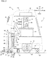
- Fig. 2 is a schematic diagram of the floor cleaner 10.
- the floor cleaner 10 includes a body 11 and functional units included in the body 11. More specifically, the body 11 includes a traveling assembly 12 (an example of a driving force transmitter in an aspect of the present invention), motors 13, a battery 14, a suction unit 15, a collection box 16 (an example of a collection box in an aspect of the present invention), a support holder 17, a suction nozzle 18 (an example of a suction nozzle in an aspect of the present invention), an extension nozzle 19 (an example of an extension nozzle in an aspect of the present invention), an operation unit 20, a display panel 21, a holder movement assembly 50, and a control unit 40.
- a traveling assembly 12 an example of a driving force transmitter in an aspect of the present invention
- motors 13 a battery 14
- a suction unit 15 a collection box 16 (an example of a collection box in an aspect of the present invention)
- a support holder 17 an example of a suction nozzle 18
- the body 11 includes an exterior cover 11A defining the exterior of the body 11.
- the body 11 includes a chassis 11B in its lower portion.
- the chassis 11B is located substantially parallel to the floor surface 23.
- the body 11 includes a support frame for supporting the above functional units as appropriate.
- the body 11 includes the traveling assembly 12 in its lower portion.
- the traveling assembly 12 which is attached to the chassis 11B, maintains the traveling posture of the body 11 and transmits the moving force of the body 11 in the traveling direction to the floor surface 23.
- the traveling assembly 12 includes a pair of traveling wheels 121 and four casters 122.
- the wheels 121 are rotatably supported in the middle of the chassis 11B in the front-rear direction and at the two ends of the chassis 11B in the width direction D3.
- the four casters 122 maintain the traveling posture of the body 11 and are rotatably supported at two front ends and two rear ends of the chassis 11B.
- the floor surface 23 supports the outer peripheral surfaces of the wheels 121 and the casters 122. The body 11 is thus maintained in the traveling posture shown in Figs. 1 and 2 .
- Each wheel 121 includes a rotational shaft connected to an output shaft of the motor 13 through a transmission such as a reduction gear.
- the motor 13 is driven to output a rotational driving force from the output shaft, the rotational driving force of the motor 13 is transmitted to the corresponding wheel 121.
- the motor 13 is located separately for each of the pair of wheels 121.
- driving of each motor 13 is individually controlled to control the rotational speed of the corresponding wheel 121,
- the rotational speed of each wheel 121 is controlled at the same speed, the floor cleaner 10 travels straight.
- the rotational speed of each wheel 121 is controlled at a different speed, the floor cleaner 10 turns on the wheel 121 with a lower rotational speed.
- the suction unit 15 is located above the battery 14 (described later) inside the body 11.
- the suction unit 15 generates a suction force for sucking air through the suction nozzle 18 (described later).
- the suction unit 15 includes multiple suction fans 151 (blowers), a suction manifold 152, and an exhaust manifold 153.
- the suction manifold 152 includes three suction ports 154 that align with one another in the width direction D3.
- the suction ports 154 each receive a corresponding flexible hose 24 for sucking air.
- the exhaust manifold 153 receives one end of an exhaust duct (not shown).
- the other end of the exhaust duct is connected to the chassis 11B, and has an outlet located in a space between the chassis 11B and the floor surface 23.
- the suction fans 151 are driven to draw air through inlets at distal ends of the flexible hoses 24.
- the air passes through the flexible hoses 24, the suction manifold 152, the suction fans 151, the exhaust manifold 153, and the exhaust duct, and is then discharged outside through the outlet.
- the battery 14 is located in a central portion of the body 11.
- the battery 14 supplies power for driving the motors 13 and the suction fans 151.
- the battery 14 also supplies driving power to a motor 62 (refer to Fig. 9 ) for rotationally driving rotary brushes 26 (described later), a motor 30 (refer to Fig. 13 ) for rotationally driving the extension nozzle 19 (described later), and a motor 19C (refer to Fig. 14 ) for rotationally driving an extension brush 19A (described later).
- the battery 14 also supplies driving power to a motor 56 (refer to Fig. 9 ) for raising and lowering the holder movement assembly 50 (described later).
- the collection box 16 is located on a back surface of the body 11.
- the collection box 16 attached to the body 11 is covered with a cover 162.
- the body 11 includes, on its back surface, the support holder 17 for holding the collection box 16 in a detachable manner.
- the collection box 16 is attached to this support holder 17 in a detachable manner.
- the cover 162 is attached to the support holder 17.
- the support holder 17 has three suction ports 174.
- the suction ports 174 extend through the front surface of the support holder 17 to an exhaust port of the collection box 16. Each suction port 174 receives an end of the corresponding flexible hose 24.
- the support holder 17 includes the suction nozzle 18 in its lower portion and the extension nozzle 19 in its side portion. The nozzles 18 and 19 communicate with the collection box 16.
- the suction unit 15 is driven to draw air with the suction nozzle 18 and the extension nozzle 19, which flows through the collection box 16 into the flexible hoses 24.
- the collection box 16, the support holder 17, and the suction nozzle 18 will be described in detail later.
- Figs. 3 and 4 are external rear perspective views of the floor cleaner 10.
- the extension nozzle 19 is located in a left portion of the support holder 17.
- the support holder 17 includes, on its left, a compartment 176 (described later) that can accommodate the extension nozzle 19.
- the extension nozzle 19 is supported by the support holder 17. More specifically, the extension nozzle 19 is supported by the support holder 17 in a manner switchable between a retracted posture (an example of a first posture in an aspect of the present invention) and a lateral cleaning posture (an example of a second posture in an aspect of the present invention). In the retracted posture, the extension nozzle 19 is retracted in the compartment 176 as shown in Figs. 1 and 3 .
- the extension nozzle 19 is turned leftward (laterally) from inside the compartment 176 to lie on its side, as shown in Figs. 4 and 7 , to clean the floor surface 23 on the left of the body 11.
- the extension nozzle 19 is supported in a manner pivotable between the retracted posture and the lateral cleaning posture about a pivot shaft near the lower end of the support holder 17.
- Fig. 3 shows the extension nozzle 19 in the retracted posture.
- Fig. 4 shows the extension nozzle 19 in the lateral cleaning posture. The extension nozzle 19 will be described in detail later.
- the operation unit 20 is located on an upper back surface of the body 11.
- the operation unit 20 is attached to the exterior cover 11A.
- the operation unit 20 is operable by an operator, and is, for example, a terminal device with a touchscreen operable by touch.
- the operation unit 20 can receive input of various items of information for the floor cleaner 10, including information about traveling routes, cleaning areas, the time of day for cleaning, and the home position.
- the input cleaning information is transferred to the control unit 40 and used for traveling control by the control unit 40.
- the display panel 21 is located on a front surface of the body 11.
- the display panel 21 is, for example, a liquid crystal display panel.
- Various messages are displayed on the display panel 21 by the control unit 40 during cleaning. These messages include a cleaning status message indicating cleaning currently being performed or a guidance message about a floor currently being cleaned.
- the holder movement assembly 50 is located inside the body 11 on the back surface of the body 11 as shown in Fig. 2 .
- the holder movement assembly 50 supports the support holder 17 in a manner movable in the vertical direction D1, and transmits a driving force to move the support holder 17 in the vertical direction D1.
- the control unit 40 controls the motor 56 to raise the support holder 17 from a cleaning position (initial position) to a maintenance position.
- the control unit 40 then causes the support holder 17 to be held at the maintenance position.
- the control unit 40 controls the motor 56 to lower the support holder 17 to the cleaning position.
- the floor cleaner 10 When the remaining battery level decreases below a threshold, the floor cleaner 10 returns to the home position, and the control unit 40 controls the motor 56 to raise the support holder 17 to a charging position. When the support holder 17 is at the charging position, the floor cleaner 10 is connected to a charger (not shown) to start charging the battery 14.
- the control unit 40 is located in an upper portion of the body 11.
- the control unit 40 controls operations including traveling of the floor cleaner 10, driving of the suction fans 151 of the suction unit 15, driving of the rotary brushes 26 and the extension brush 19A, driving of the extension nozzle 19, raising and lowering of the support holder 17 with the holder movement assembly 50, and displaying on the display panel 21.
- the control unit 40 includes control devices such as a central processing unit (CPU), a read-only memory (ROM), and a random-access memory (RAM), and a storage medium or device such as a hard disk drive (HDD) and a flash memory.
- the CPU is a processor for performing various computations.
- the ROM is a non-volatile memory prestoring control programs, such as a basic input-output system (BIOS) and an operating system (OS), for causing the CPU to perform various processes.
- the RAM is a volatile or non-volatile memory for storing various items of information, and is used as a memory area (work area) for temporarily storing various processes to be performed by the CPU.
- the control unit 40 causes the CPU to execute various control programs prestored in the ROM or storage device to control operations including traveling of the floor cleaner 10, driving of the suction fans 151, driving of the rotary brushes 26 and the extension brush 19A, driving of the extension nozzle 19, and raising and lowering of the support holder 17.
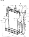
- Figs. 5 and 6 are perspective views of the floor cleaner 10 without the exterior cover 11A.
- the support holder 17 is located on the back surface of the floor cleaner 10.
- the body 11 contains a plate-like vertical frame 11C extending upward from the rear end of the chassis 11B.
- the support holder 17 is attached to the vertical frame 11C.
- the support holder 17 is supported by the vertical frame 11C of the body 11 in a manner movable in the vertical direction D1, as described later.
- Fig. 7 is a perspective view of the support holder 17.
- the support holder 17 includes a base 171 extending in the vertical direction D1, and a box compartment 172 fastened to the base 171.
- the base 171 is formed by bending a metal plate.
- the base 171 includes a base plate 171A attached to the vertical frame 11C, and side plates 171B and 171C protruding rearward from the two ends of the base plate 171A in the width direction D3.
- the base plate 171A receives, at its upper end, three suction ports 174 (refer to Fig. 2 ) for receiving the ends of the flexible hoses 24.
- Each suction port 174 is a cylinder protruding frontward from the base plate 171A.
- the base plate 171A has three communicating holes 175 at the upper end in the rear surface of the base plate 171A.
- the communicating holes 175 align with the suction ports 174.
- the collection box 16 contains an air filter 169 (refer to Fig. 9 ) for filtering debris, such as dust, out of air discharged from the outlet ports 167 to purify the air.
- the air filter 169 include a chemical filter, a high-efficiency particulate air (HEPA) filter, and an ultra-low particulate air (ULPA) filter.
- the box compartment 172 supports the collection box 16 in a detachable manner.
- the box compartment 172 is fastened to the rear surface of the base 171, and is located at the center of the base 171 in the width direction D3.
- the box compartment 172 is formed by bending a metal plate.
- the box compartment 172 includes an attachment plate 172A fastened to the base 171, and side plates 172B and 172C protruding rearward from the two ends of the attachment plate 172A in the width direction D3.
- the box compartment 172 which is shorter than the base 171 in the width direction D3, is retracted in a space defined by the side plates 171B and 171C of the base 171, as shown in Fig. 7 .
- the box compartment 172 is open rearward and upward.
- the collection box 16 can be lifted diagonally rearward and upward from the box compartment 172 when a door (not shown) on the cover 162 is open. This allows easy detachment of the collection box 16 from the box compartment 172.
- Fig. 8A is a side view of a rear portion of the floor cleaner 10 with the collection box 16 attached to the box compartment 172.
- Fig. 8B is a side view of the rear portion of the floor cleaner 10 with the collection box 16 detached from the box compartment 172.
- the box compartment 172 includes a bottom surface 172D having a rectangular opening 177 elongated in the width direction D3.
- the opening 177 communicates with the suction nozzle 18 (described later).
- an inlet 168 (refer to Figs. 8B and 11 ) (an example of a first inlet in an aspect of the present invention) in a bottom surface 16A of the collection box 16 aligns with the opening 177.
- the rotary brushes 26 are exposed and can be visually checked from vertically above.
- the box compartment 172 has an opening 178 (refer to Fig. 7 ) in a lower portion of the left side plate 172B.
- the opening 178 communicates with the extension nozzle 19.
- a side inlet 161 (refer to Fig. 11 ) (an example of a second inlet in an aspect of the present invention) in a lateral side surface 16C of the collection box 16 aligns with the opening 178.
- This allows the collection box 16 to communicate with the extension nozzle 19 to collect, through the side inlet 161, dust (an example of second suction matter in an aspect of the present invention) sucked by the extension nozzle 19 together with air.
- the collection box 16 which is a hollow box, can collect debris such as dust (suction matter) sucked through a suction hole 181 (refer to Fig. 8 ) of the suction nozzle 18 (described later).
- the collection box 16 is shaped in a rectangle that is thinner in the front-rear direction D2.
- the collection box 16 contains a sheet flap 163 for opening and closing the inlet 168.
- the flap 163 is formed from an elastic synthetic resin, such as a PET resin.
- the flap 163 has a front end fixed to the bottom surface 16A of the collection box 16, and extends diagonally rearward and upward from this fixed end.
- the flap 163 has an extended end in contact with a rear side surface 16B of the collection box 16.
- the extended end of the flap 163 is a free end pivotable about the fixed end of the flap 163.
- the flap 163 With no air suction being performed, the flap 163 is urged toward the side surface 16B by its elasticity. The flap 163 has its extended end in contact with the side surface 16B to cover the inlet 168, without the debris in the collection box 16 dropping outside through the inlet 168. When the collection box 16 is detached from the box compartment 172, the flap 163 covers the inlet 168, without the debris dropping outside through the inlet 168.
- the collection box 16 With air suction being performed by driving the suction fans 151, the collection box 16 has a negative pressure that causes air to flow in through the inlet 168. Such air inflow causes the flap 163 to flex forward against the urging force toward the side surface 16B. The flap 163 then no longer covers the inlet 168, allowing smooth air suction through the inlet 168 into the collection box 16. When the suction fans 151 stop being driven, the flap 163 returns to its original position to cover the inlet 168 again.
- the flap 163 may be driven as controlled by the control unit 40.
- a solenoid 164 may be located below the flap 163.
- the solenoid 164 is pivotably supported by the support holder 17 and protrudes upward from the opening 177 in the box compartment 172.
- the control unit 40 drives the suction fans 151 and applies a predetermined driving force (current) to the solenoid 164. This causes the solenoid 164 to pivot and push up the flap 163, uncovering the inlet 168.
- the solenoid 164 returns to its original position to cause the flap 163 to cover the inlet 168 again.
- the suction nozzle 18 sucks debris, such as dust, together with air from the floor surface 23 when the suction fans 151 are operating.
- the suction nozzle 18 has the suction hole 181 above the floor surface 23 with a predetermined clearance ⁇ T between the suction hole 181 and the floor surface 23. In other words, the suction hole 181 is above away from the floor surface 23 with the clearance ⁇ T between them.
- the suction nozzle 18 is located at the lower end of the support holder 17. In the present embodiment, the suction nozzle 18 is integral with the box compartment 172 of the support holder 17.
- the suction nozzle 18 and the box compartment 172 are vertically separated from each other by the bottom surface 172D (refer to Fig. 7 ).
- the collection box 16 and the box compartment 172 supporting the collection box 16 are located vertically above the suction nozzle 18.
- the outer peripheral wall 182 is open downward to define the suction hole 181 described above.
- the suction nozzle 18 includes an elastic sealing sheet 185 located at the rear edge of the suction hole 181 and extending to the floor surface 23.
- the sealing sheet 185 is shaped in a rectangle elongated in the width direction D3 and bonded to the entire area of the suction hole 181 in the width direction D3.
- the sealing sheet 185 seals the clearance ⁇ T between the rear edge of the suction hole 181 and the floor surface 23.
- the suction nozzle 18 includes a pair of rotatable rotary brushes 26 (26A and 26B).
- the rotary brushes 26 correspond to a first rotary brush in an aspect of the present invention.
- the rotary brushes 26 align with each other in the front-rear direction D2.
- Each rotary brush 26 has a rotational shaft 261 (refer to Fig. 9 ) extending through and rotatably supported by side plates 184 (refer to Fig. 9 ) at the two ends of the suction nozzle 18 in the width direction D3.
- the suction nozzle 18 in the present embodiment includes the pair of rotary brushes 26, the suction nozzle 18 may include one or three or more rotary brushes 26, instead of the pair of (two) rotary brushes 26.
- the support holder 17 includes the motor 62 for supplying a driving force to the rotary brushes 26.
- Fig. 9 is a schematic cross-sectional view taken along line XII-XII in Fig. 2 .
- the motor 62 is accommodated in a compartment 179 between the side plate 172C and the side plate 171C.
- the rotational driving force of the motor 62 is transmitted to the rotational shaft 261 through a transmission 64 including multiple gears.
- the motor 62 is driven by the control unit 40 during traveling of the floor cleaner 10 to rotate the rotary brushes 26, thus efficiently collecting debris from the floor surface 23.
- the front rotary brush 26A of the pair of rotary brushes 26 has rollers 60 rotatably supported on the rotational shaft 261 of the rotary brush 26A.
- the rollers 60 are attached to the two ends of the rotational shaft 261. More specifically, as shown in Fig. 9 , the rollers 60 are attached to the two ends of the rotational shaft 261 protruding outward from the side plates 184 of the suction nozzle 18 in the width direction D3.
- the rollers 60 are supported by the support holder 17 to have circumferences between the edge of the suction hole 181 and the floor surface 23. In other words, as shown in Fig. 9 , when the floor cleaner 10 is in the traveling posture shown in Fig. 1 , the rollers 60 protrude downward from the edge of the suction hole 181 but are not in contact with the floor surface 23.
- the collection box 16 is attached to the support holder 17 in a detachable manner, as described above. More specifically, the collection box 16 is placed on and attached to the bottom surface 172D (refer to Fig. 7 ) of the box compartment 172. Thus, the inlet 168 (refer to Fig. 11 ) in the bottom surface 16A of the collection box 16 directly communicates with the opening 177 in the bottom surface 172D of the box compartment 172.
- the suction nozzle 18 is located vertically below the opening 177, and includes the rotary brushes 26. Thus, the collection box 16 is located vertically above the rotary brushes 26 with the opening 177 between the collection box 16 and the rotary brushes 26.
- the inlet 168 of the collection box 16 is located vertically above (immediately above) and faces the rotary brushes 26.
- This structure allows the rotary brushes 26 to be exposed through the opening 177 when the collection box 16 is detached from the box compartment 172, as shown in Fig. 7 .
- This allows the user to easily visually check the rotary brushes 26 from above to determine the state of the rotary brushes 26.
- the user can detach the collection box 16 from the box compartment 172 for easy maintenance of the rotary brushes 26. The user can thus easily access the rotary brushes 26, improving the maintainability of the rotary brushes 26.
- the inlet 168 of the collection box 16 directly communicates with the suction nozzle 18.
- This structure allows debris sucked by the suction nozzle 18 together with air to be directly collected into the collection box 16 without a pipe. This eliminates clogging with debris moving through the suction nozzle 18 to the collection box 16. The structure also shortens the distance by which debris moves, thus improving suction efficiency.
- the inlet 168 may be in a front or rear side surface of the collection box 16 and may laterally face the rotary brushes 26. This structure allows the user to visually check the rotary brushes 26 from the lateral side when the collection box 16 is detached from the box compartment 172, allowing maintenance of the rotary brushes 26.
- a known floor cleaner is designed to turn about the center of its casing, and has a circular profile in a plan view (as viewed from above). Such a floor cleaner tends to have a larger circular profile to provide a space (accommodating space) for functional units (e.g., a battery) included in the body.
- the floor cleaner may fail to pass through and clean the passageway.
- the floor cleaner may have an elongated profile with a depth W2 larger than a width W1 in a plan view.
- the floor cleaner having such an elongated profile provides a space for accommodating the functional units, and can also travel on and clean narrow passageways.
- the floor cleaner having such an elongated profile may have some difficulties below.
- Fig. 12 is a schematic diagram of a floor cleaner 100 having an elongated profile illustrating its travel according to a reference embodiment.
- Fig. 12 shows the floor cleaner 100 passing through a narrow passageway, then traveling and cleaning near a wall, and then changing its traveling direction (turning) upward in Fig. 12 .
- the floor cleaner 100 turns about a rotation center C0 (rotation axis).
- Fig. 12 shows a turning range R1 of the floor cleaner 100.
- the floor cleaner 100 may have its rear end (right rear end in Fig. 12 ) in contact with the wall surface, and cannot turn properly.
- the floor cleaner 100 repeatedly turns left gently while traveling forward and turns right while traveling rearward (three-point turn). The floor cleaner 100 thus takes a long time for cleaning, decreasing cleaning efficiency.
- the floor cleaner 10 has an elongated profile in a plan view, and includes the extension nozzle 19 extendable in the lateral direction with respect to the traveling direction and pivotable rearward.
- the floor cleaner 10 thus has a space for accommodating the functional units, can travel on and clean narrow passageways, and also has improved cleaning efficiency near walls.
- the structure of the extension nozzle 19 will now be described in detail.
- the extension nozzle 19 switches from the retracted posture to the lateral cleaning posture.
- the control unit 40 obtains information about the current position of the floor cleaner 10.
- the control unit 40 outputs, to the motor 30 (refer to Figs. 7 , 14 , and 15 ), a first control signal (drive signal) for switching the extension nozzle 19 from the retracted posture to the lateral cleaning posture.
- the motor 30 then generates a driving force in accordance with the first control signal to rotationally drive and switch the extension nozzle 19 to the lateral cleaning posture.
- the control unit 40 outputs, to the motor 30, a second control signal (drive signal) for switching the extension nozzle 19 from the lateral cleaning posture to the retracted posture.
- the motor 30 then generates a driving force in accordance with the second control signal to rotationally drive and switch the extension nozzle 19 to the retracted posture.
- the control unit 40 may control the posture of the extension nozzle 19 based on the detection result from a sensor (not shown) included in the floor cleaner 10. For example, in response to the sensor detecting a passageway width larger than a predetermined width or detecting a wall, the control unit 40 outputs the first control signal. In response to the sensor detecting a passageway width not larger than the predetermined width or detecting an obstacle, the control unit 40 outputs the second control signal.
- Fig. 13A is a schematic diagram of the extension nozzle 19 switching from the retracted posture to the lateral cleaning posture.
- the extension nozzle 19 switches to the lateral cleaning posture by pivoting about a pivot shaft C1 toward the floor surface 23.
- the floor cleaner 10 including the extension nozzle 19 can clean narrow passageways when the extension nozzle 19 is in the retracted posture, and can clean a wider area using the rotary brushes 26 (first rotary brushes in an aspect of the present invention) and the extension brush 19A (a second rotary brush in an aspect of the present invention) when the extension nozzle 19 is in the lateral cleaning posture.
- the extension nozzle 19 is also supported in a manner pivotable from the lateral cleaning posture rearward with respect to the traveling direction. As shown in Fig. 13B , for example, the extension nozzle 19 pivots rearward about a pivot shaft C2 upon contact with an obstacle, a wall, or other objects when the floor cleaner 10 is traveling with the extension nozzle 19 in the lateral cleaning posture. This structure avoids damage to the extension nozzle 19. When the floor cleaner 10 passes or moves away from the obstacle, the extension nozzle 19 pivots forward about the pivot shaft C2 to return to its original position.
- Figs. 14 and 15 are schematic diagrams of the extension nozzle 19 showing its specific structure.
- the extension nozzle 19 is pivotably connected to extension nozzle holders 31 and 32.
- the extension nozzle holder 31 has one end fixed at the opening 178 (refer to Fig. 7 ) of the box compartment 172 and the other end receiving one end of the extension nozzle holder 32.
- the extension nozzle holder 32 is connected to the extension nozzle holder 31 in a manner pivotable about the pivot shaft C1 (refer to Figs. 14 and 15 ).
- the other end of the extension nozzle holder 32 is received in the extension nozzle 19.
- the extension nozzle 19 is connected to the extension nozzle holder 32 in a manner pivotable about the pivot shaft C2 (refer to Fig. 14 ).
- the extension nozzle holder 32 is connected to a belt 30A for transmitting the rotational driving force from the motor 30.
- the control unit 40 includes various processing units such as a position obtainer 411, a travel controller 412, and an extension nozzle controller 413.
- the control unit 40 causes the CPU to perform various processes in accordance with various control programs, thus serving as the various processing units.
- At least one of the processing units included in the control unit 40 may include an electronic circuit.
- the position obtainer 411 obtains the current position of the floor cleaner 10.
- the travel controller 412 controls operations including traveling of the floor cleaner 10, driving of the suction fans 151, and raising and lowering of the support holder 17, as described above.
- the travel controller 412 controls traveling of the floor cleaner 10 on a preset traveling route based on the current position obtained by the position obtainer 411.
- the extension nozzle controller 413 outputs the first control signal and the second control signal based on the current position obtained by the position obtainer 411.
- the motor 30 is driven to cause the extension nozzle holder 32 to pivot about the pivot shaft C1 through the belt 30A. This causes the extension nozzle 19 to switch between the retracted posture and the lateral cleaning posture.
- the extension nozzle holder 32 has an opening 32A (refer to Fig. 14 ).
- the opening 32A aligns with an opening 31A of the extension nozzle holder 31, and communicates with the internal space of the extension nozzle holder 31. This allows communication between the internal spaces of the extension nozzle holders 31 and 32, and thus allows communication between the extension nozzle 19 and the collection box 16.
- an airflow path forms from the extension nozzle 19 to the collection box 16.
- the collection box 16 can collect, through the side inlet 161 (refer to Fig. 11 ), dust sucked by the extension nozzle 19 together with air.
- the opening 32A is out of alignment with the opening 31A of the extension nozzle holder 31, thus blocking the airflow path from the extension nozzle 19 to the collection box 16.
- the collection box 16 collects, through the inlet 168, debris sucked by the suction nozzle 18.
- the collection box 16 collects, through the inlet 168, debris sucked by the suction nozzle 18, and also collects, through the side inlet 161, debris sucked by the extension nozzle 19.
- the floor cleaner 10 collects, into the collection box 16, debris sucked by the suction nozzle 18 and debris sucked by the extension nozzle 19 through different paths.
- the floor cleaner 10 may stop driving the suction nozzle 18 and drive the extension nozzle 19 alone to collect debris sucked by the extension nozzle 19.
- the extension nozzle 19 includes a coil spring 19B (an example of a retainer in an aspect of the present invention).
- the coil spring 19B has one end fixed to the extension nozzle holder 32, and the other end fixed to the body (exterior frame) of the extension nozzle 19.
- the extension nozzle 19 is retained by the coil spring 19B to extend in a direction orthogonal to the traveling direction of the floor cleaner 10.
- the extension nozzle 19 is retained by the coil spring 19B to extend along an extension of the rotary brushes 26.
- the coil spring 19B includes a tension coil spring designed to receive a tensile force when the extension nozzle 19 is at a position shown in Fig. 14 (retention position).
- the extension nozzle 19 pivots rearward about the pivot shaft C2 against the tensile force from the coil spring 19B.
- the tensile force from the coil spring 19B causes the extension nozzle 19 to pivot about the pivot shaft C2 to return to the retention position.
- the coil spring 19B is used as an example elastic member in the present embodiment, the coil spring 19B may be replaced with, for example, an elastic cord formed from rubber.
- the extension nozzle 19 includes the motor 19C.
- the motor 19C receives a control signal (drive signal) from the travel controller 412 of the control unit 40.
- the motor 19C generates a driving force in accordance with the control signal to drive the extension brush 19A to pivot.
- the extension nozzle 19 is pivotable in a direction to reduce a collision force upon colliding with obstacles, walls, or other objects. This structure avoids damage to the extension nozzle 19, obstacles, walls, or other objects.
- the extension nozzle 19 may also be pivotable in the traveling direction. In this case, upon colliding with obstacles, walls, or other objects rearward from the extension nozzle 19, the extension nozzle 19 may also pivot in the same manner to avoid damage.
- Fig. 16 is a schematic diagram of the floor cleaner 10 illustrating its travel according to the present embodiment.
- Fig. 16 shows the floor cleaner 10 passing through a narrow passageway, then traveling and cleaning near a wall, and then changing its traveling direction (turning) upward in Fig. 16 .
- the floor cleaner 10 turns about the rotation center C0 (rotation axis).
- Fig. 16 shows the turning range R1 of the floor cleaner 10.
- the floor cleaner 10 approaches the wall and travels along the wall surface to have its turning range R1 excluding the wall surface.
- a predetermined distance L1 is set for the floor cleaner 10.
- the predetermined distance L1 corresponds to a position outside an end R11 of the turning range R1 in the width direction D3.
- the travel controller 412 controls the floor cleaner 10 to travel parallel to the wall surface.
- the floor cleaner 10 can thus avoid contact with the wall surface when, for example, the floor cleaner 10 turns about the rotation center C0.
- the control unit 40 In response to the floor cleaner 10 approaching the wall, the control unit 40 outputs, to the motor 30, the first control signal (drive signal) for switching the extension nozzle 19 from the retracted posture to the lateral cleaning posture. In response to the first control signal, the extension nozzle 19 switches to the lateral cleaning posture by pivoting about the pivot shaft C1 toward the floor surface 23. As shown in Fig. 16 , in the lateral cleaning posture, the extension nozzle 19 has a protruding end 19E in the width direction D3 generally (or substantially) aligning with the end R11 of the turning range R1 of the floor cleaner 10 in the width direction D3 when the floor cleaner 10 is viewed in the traveling direction.
- the width direction D3 is orthogonal to the traveling direction and corresponds to the width direction in an aspect of the present invention.
- the travel controller 412 can cause the floor cleaner 10 to travel along the wall surface while keeping the predetermined distance L1 from the wall surface and having the turning range R1 of the floor cleaner 10 excluding the wall surface in a plan view.
- the distance from the protruding end 19E of the extension nozzle 19 to the wall surface is the same as the distance from the end R11 of the turning range R1 to the wall surface, keeping a predetermined clearance between the protruding end 19E and the wall surface.
- the extension nozzle 19 has the protruding end 19E out of contact with the wall surface keeping a predetermined clearance from the wall surface when the floor cleaner 10 travels parallel to the wall surface at the distance to the wall surface reaching the predetermined distance L1. This allows the floor cleaner 10 to travel and clean near the wall surface with the extension nozzle 19 out of contact with the wall surface.
- the floor cleaner 10 When traveling and cleaning near the wall and then changing the traveling direction (or turning) upward as shown in Fig. 16 , the floor cleaner 10 can avoid having the right rear end of its body in contact with the wall surface.
- the extension nozzle 19 comes in contact with the wall surface but pivots rearward about the pivot shaft C2 (refer to Fig. 14 ). This structure avoids damage to the extension nozzle 19.
- the extension nozzle 19 pivots forward about the pivot shaft C2 to return to its original position.
- the floor cleaner 10 has an elongated profile having a larger dimension in the traveling direction (depth W2) than its dimension in the width direction D3 (width W1).
- the floor cleaner 10 having such a profile provides a space for accommodating the functional units (e.g., a battery) in the body, and can also travel on and clean narrow passageways.
- the floor cleaner 10 includes the extension nozzle 19 switchable between the retracted posture and the lateral cleaning posture. In the lateral cleaning posture, the extension nozzle 19 has the protruding end 19E in the width direction D3 aligning with the end R11 of the turning range R1 of the floor cleaner 10 in the width direction D3 when the floor cleaner 10 is viewed in the traveling direction.
- the floor cleaner 10 with this structure can travel and clean near the wall with the extension nozzle 19 out of contact with the wall surface by keeping the predetermined distance L1 (refer to Fig. 16 ) from the wall surface and having the turning range R1 excluding the wall surface.
- the floor cleaner 10 avoids contact of its body with the wall surface.
- the floor cleaner 10 also avoids damage to the extension nozzle 19 by pivoting the extension nozzle 19 rearward about the pivot shaft C2 (refer to Fig. 14 ) upon contact with the wall surface.
- the floor cleaner 10 in an aspect of the present invention has a space for accommodating the functional units and can travel on and clean narrow passageways with improved cleaning efficiency near walls.
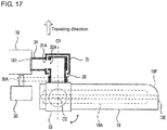
- the protruding end 19E of the extension nozzle 19 may have a corner in the traveling direction with an arc-shaped surface 19F (or sloped surface) (an arc-shaped or a sloped corner) in a plan view of the floor cleaner 10.
- the extension nozzle 19 may have a roller 19G on a corner of the protruding end 19E in the traveling direction.
- the structures shown in Figs. 17 and 18 allow the extension nozzle 19 to easily pivot rearward upon contact with a wall surface when the floor cleaner 10 changes the direction (or turns). This structure effectively avoids damage to the extension nozzle 19.
- the coil spring 19B may retain the extension nozzle 19 tilted in a direction (rearward) opposite to the traveling direction by a predetermined angle d1 relative to the width direction D3.
- the extension nozzle 19 more easily pivots rearward upon contact with a wall surface. This structure effectively avoids damage to the extension nozzle 19.
- the extension nozzle 19 may include two or more of the structures shown in Figs. 17 to 19 combined together.
- the extension nozzle 19 may have the protruding end 19E in the width direction D3 outside the turning range R1 when the floor cleaner 10 is viewed in the traveling direction. In other words, the extension nozzle 19 may have a length to protrude from the turning range R1.
- the extension nozzle 19 may come in contact with a wall surface at the distance between the floor cleaner 10 and the wall surface yet to reach the predetermined distance L1 as shown in, for example, Fig. 20 .
- the floor cleaner 10 travels near the wall, with the extension nozzle 19 in contact with the wall surface.
- the extension nozzle 19 can thus clean a corner of the wall surface.
- the extension nozzle 19 may include, at a corner of the protruding end 19E, the roller 19G (refer to Fig. 18 ) rotatable upon contact with the wall surface.
- the extension nozzle 19 may be located in a right portion of the support holder 17, or may be located in each of right and left portions of the support holder 17. When the extension nozzle 19 is located in each of right and left portions, the two extension nozzles 19 may be controlled independently of each other by the control unit 40 (extension nozzle controller 413). The extension nozzle 19 may be manually switchable between the retracted posture and the lateral cleaning posture.
- a floor cleaner 10 may include a collection box 16 exposed through a body 11.
- the collection box 16 may be detachable from the body 11 without a cover 162 or a door (not shown) being removed.
Landscapes
- Engineering & Computer Science (AREA)
- Mechanical Engineering (AREA)
- Nozzles For Electric Vacuum Cleaners (AREA)
- Cleaning In General (AREA)
- Electric Vacuum Cleaner (AREA)
Abstract
Description
- This application claims priority to Japanese Patent Application No.
2019-218717 filed on December 3, 2019 - The present invention relates to an autonomous traveling cleaner that travels autonomously, and particularly to an autonomous traveling cleaner including a collection box for collecting suction matter, such as sucked dust.
- Autonomous traveling cleaners are known and called cleaning robots. An autonomous traveling cleaner travels autonomously while cleaning target surfaces such as floor surfaces by sucking air through its suction nozzle hole that is directed toward the target surfaces and sucking dust on the surfaces. The sucked dust (suction matter) is collected into a collection box attached to the cleaner.
- Recent labor shortages and increasing labor costs have caused a lack of cleaning personnel who clean wide places, such as concourses at stations or airports and shopping malls. This has increased the use of industrial autonomous traveling cleaners that are designed to travel autonomously and have high cleaning performance as well as a high degree of safety (refer to Patent Literature 1). Such autonomous traveling cleaners have collision avoidance for traveling safely without colliding with passersby, obstacles, or walls.
- Patent Literature 1: Japanese Unexamined Patent Application Publication No.
2018-112917 - Such known industrial autonomous traveling cleaners can clean narrow passages, but they travel at a certain distance from wall surfaces in view of safer operations, often leaving uncleaned areas. When cleaning large areas, such cleaners may travel a long distance for a long time, possibly having dead batteries.
- One or more aspects of the present invention are directed to an autonomous traveling cleaner with improved cleaning efficiency.
- An autonomous traveling cleaner according to one aspect of the present invention is an autonomous traveling cleaner that travels autonomously on a target surface and cleans the target surface. The autonomous traveling cleaner includes a driving force transmitter that transmits, to the target surface, a moving force of the autonomous traveling cleaner in a traveling direction with a body of the autonomous traveling cleaner in a traveling posture, a suction nozzle including a first rotary brush that sweeps the target surface and sucks first suction matter collected by the first rotary brush, an extension nozzle extendable laterally with respect to the traveling direction and including a second rotary brush that sweeps the target surface to suck second suction matter collected by the second rotary brush, and a collection box including an inlet that collects, through the inlet, the first suction matter sucked by the suction nozzle and the second suction matter sucked by the extension nozzle. The autonomous traveling cleaner has an elongated profile having a larger dimension in the traveling direction than in a width direction orthogonal to the traveling direction. The extension nozzle is switchable between a first posture and a second posture. The extension nozzle in the first posture is positioned without laterally protruding from the autonomous traveling cleaner and has an airflow path being blocked from the extension nozzle to the collection box. The extension nozzle in the second posture is positioned to laterally protrude from the autonomous traveling cleaner and has an airflow path forming from the extension nozzle to the collection box. The extension nozzle in the second posture is pivotable in a direction opposite to the traveling direction. The extension nozzle in the second posture has a protruding end in the width direction to be aligned with an end of a turning range of the autonomous traveling cleaner in the width direction, when the autonomous traveling cleaner is viewed in the traveling direction.
- The autonomous traveling cleaner with this structure has an elongated profile having a smaller width than a depth. The autonomous traveling cleaner can travel and clean along a wall with the extension nozzle out of contact with the wall surface by, for example, keeping a predetermined distance from the wall surface and thus having its turning range excluding the wall surface. The autonomous traveling cleaner can avoid contact of its body with the wall surface when changing the direction (or turning) near the wall. The autonomous traveling cleaner includes the extension nozzle pivotable rearward upon contact with the wall surface when the autonomous traveling cleaner changes the direction near the wall. This structure avoids damage to the extension nozzle. The autonomous traveling cleaner has a space for accommodating the functional units and can travel on and clean narrow passageways with improved cleaning efficiency near walls.
- In the autonomous traveling cleaner in an aspect of the present invention, the protruding end of the extension nozzle has an arc-shaped corner in the traveling direction in a plan view of the autonomous traveling cleaner. In the autonomous traveling cleaner in an aspect of the present invention, the extension nozzle includes a roller on a corner of the protruding end in the traveling direction in a plan view of the autonomous traveling cleaner.
- The autonomous traveling cleaner with this structure includes the extension nozzle easily pivotable rearward upon contact with a wall surface when the autonomous traveling cleaner changes the direction (or turns). This structure effectively avoids damage to the extension nozzle.
- The autonomous traveling cleaner in an aspect of the present invention further includes a travel controller that controls traveling of the autonomous traveling cleaner. The travel controller causes the autonomous traveling cleaner to travel along a wall surface within the turning range to exclude the wall surface in a plan view of the autonomous traveling cleaner.
- The autonomous traveling cleaner with this structure keeps a predetermined distance and thus has its turning range excluding the wall surface. The autonomous traveling cleaner can thus travel and clean near the wall with the extension nozzle out of contact with the wall surface.
- In the autonomous traveling cleaner in an aspect of the present invention, the extension nozzle switches from the first posture to the second posture in response to the autonomous traveling cleaner traveling at a preset place on a traveling route.
- The autonomous traveling cleaner with this structure has the extension nozzle protruding laterally when, for example, traveling on preset wide passageways or passageways near walls.
- The autonomous traveling cleaner in an aspect of the present invention further includes a retainer that applies an urging force to the extension nozzle to retain the extension nozzle in the second posture. In response to an external force applied to the extension nozzle, the retainer causes, against the urging force, the extension nozzle to pivot, from the second posture, in a direction in which the external force is applied, and returns the extension nozzle in the second posture with the urging force in response to the external force removed from the extension nozzle.
- The autonomous traveling cleaner with this structure has the extension nozzle protruding laterally to pivot rearward upon contact with an obstacle during autonomous traveling. This structure avoids damage to the extension nozzle.
- In the autonomous traveling cleaner in an aspect of the present invention, the retainer includes a tension coil spring. The tension coil spring has an end fixed to the extension nozzle. The tension coil spring applies a tensile force to the extension nozzle to retain the extension nozzle in the second posture.
- This structure allows the pivoted extension nozzle to return to and be retained in the second posture.
- In the autonomous traveling cleaner in an aspect of the present invention, the retainer retains the extension nozzle tilted opposite to the traveling direction at a predetermined angle with respect to the width direction when the extension nozzle is in the second posture and free from the external force.
- The autonomous traveling cleaner with this structure has the extension nozzle that more easily pivots rearward upon contact with a wall surface when changing the direction (turning). This structure effectively avoids damage to the extension nozzle.
- In the autonomous traveling cleaner in an aspect of the present invention, the inlet includes a first inlet in a bottom surface of the collection box, and a second inlet in a side surface of the collection box. The collection box collects, through the first inlet, the first suction matter sucked by the suction nozzle and stops collection with the extension nozzle when the extension nozzle is in the first posture. The collection box collects, through the first inlet, the first suction matter sucked by the suction nozzle and collects, through the second inlet, the second suction matter sucked by the extension nozzle when the extension nozzle is in the second posture.
- The autonomous traveling cleaner with this structure sucks debris with the suction nozzle when the extension nozzle is in the first posture, and sucks debris with the suction nozzle and the extension nozzle when the extension nozzle is in the second posture. The autonomous traveling cleaner has improved cleaning efficiency
- The technique according to the above aspects of the present invention improves cleaning efficiency.
-
-
Fig. 1 is an external front perspective view of a floor cleaner according to an embodiment of the present invention. -
Fig. 2 is a schematic diagram of the floor cleaner. -
Fig. 3 is an external rear perspective view of the floor cleaner having an extension nozzle in a retracted posture. -
Fig. 4 is an external rear perspective view of the floor cleaner having the extension nozzle in a lateral cleaning posture. -
Fig. 5 is a perspective view of the floor cleaner showing its internal structure. -
Fig. 6 is an enlarged view of a main part VI inFig. 5 . -
Fig. 7 is a perspective view of a support holder included in the floor cleaner. -
Fig. 8A is a side view of a rear portion of the floor cleaner with a collection box attached to the floor cleaner, andFig. 8B is a side view of the rear portion of the floor cleaner with the collection box detached from the floor cleaner. -
Fig. 9 is a schematic cross-sectional view taken along line XII-XII inFig. 2 . -
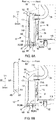
Fig. 10 is a view of an open-close assembly for a flap included in the floor cleaner. -
Fig. 11 is a perspective view of the collection box included in the floor cleaner. -
Fig. 12 is a schematic diagram of a floor cleaner illustrating its travel according to a reference embodiment. -
Fig. 13A is a schematic diagram of the floor cleaner as viewed from behind illustrating a posture change of the extension nozzle included in the floor cleaner, andFig. 13B is a schematic diagram of the floor cleaner as viewed from above illustrating the posture change of the extension nozzle included in the floor cleaner. -
Fig. 14 is a schematic diagram of a pivoting assembly for the extension nozzle as viewed from above. -
Fig. 15 is a schematic diagram of the pivoting assembly for the extension nozzle as viewed from behind. -
Fig. 16 is a schematic diagram of the floor cleaner illustrating its travel according to the embodiment of the present invention. -
Fig. 17 is a schematic diagram of an extension nozzle according to a modification of the present invention as viewed from above. -
Fig. 18 is a schematic diagram of an extension nozzle according to a modification of the present invention as viewed from above. -
Fig. 19 is a schematic diagram of an extension nozzle according to a modification of the present invention as viewed from above. -
Fig. 20 is a schematic diagram of a floor cleaner illustrating its travel according to an embodiment of the present invention. -
Fig. 21 is an external rear perspective view of a floor cleaner according to a modification of the present invention. - One or more embodiments of the present invention will now be described with reference to the drawings. The embodiments described below are mere examples of this invention and should not be construed as limiting the technical scope of the invention. A vertical direction D1, a front-rear direction D2, and a lateral or width direction D3 referred to herein are illustrated in the figures.
-
Fig. 1 is an external front perspective view of afloor cleaner 10 according to an embodiment of the present invention. The floor cleaner 10 (an example of an autonomous traveling cleaner in an aspect of the present invention) autonomously travels forward (in a traveling direction) while automatically cleaning a floor surface 23 (a target surface) of a concourse at a facility such as an airport, a station, or a shopping mall. Thefloor cleaner 10 generates a suction force for sucking air using, for example, a blower. With the suction force, thefloor cleaner 10 sucks debris, such as dirt and dust, from the floor surface together with air. Thefloor cleaner 10 then separates debris using a filter to collect the debris into a collection box 16 (refer toFig. 2 ). Thefloor cleaner 10 automatically cleans thefloor surface 23 while traveling on thefloor surface 23 based on various items of cleaning information including traveling routes and cleaning areas that are preliminarily input, the time of day for cleaning, and the home position to which thefloor cleaner 10 returns for charging. - The
floor cleaner 10 is a mere example of the autonomous traveling cleaner according to one or more embodiments of the present invention. Embodiments of the present invention may also be applicable to, for example, cleaners that clean outdoor surfaces, such as pedestrians and vehicle roads, while traveling autonomously. -
Fig. 2 is a schematic diagram of thefloor cleaner 10. As shown inFigs. 1 and2 , thefloor cleaner 10 includes abody 11 and functional units included in thebody 11. More specifically, thebody 11 includes a traveling assembly 12 (an example of a driving force transmitter in an aspect of the present invention),motors 13, abattery 14, asuction unit 15, a collection box 16 (an example of a collection box in an aspect of the present invention), asupport holder 17, a suction nozzle 18 (an example of a suction nozzle in an aspect of the present invention), an extension nozzle 19 (an example of an extension nozzle in an aspect of the present invention), anoperation unit 20, adisplay panel 21, aholder movement assembly 50, and acontrol unit 40. - As shown in
Fig. 1 , thebody 11 includes anexterior cover 11A defining the exterior of thebody 11. As shown inFig. 2 , thebody 11 includes achassis 11B in its lower portion. Thechassis 11B is located substantially parallel to thefloor surface 23. Thebody 11 includes a support frame for supporting the above functional units as appropriate. - As shown in
Fig. 2 , thebody 11 includes the travelingassembly 12 in its lower portion. The travelingassembly 12, which is attached to thechassis 11B, maintains the traveling posture of thebody 11 and transmits the moving force of thebody 11 in the traveling direction to thefloor surface 23. The travelingassembly 12 includes a pair of travelingwheels 121 and fourcasters 122. - The
wheels 121 are rotatably supported in the middle of thechassis 11B in the front-rear direction and at the two ends of thechassis 11B in the width direction D3. The fourcasters 122 maintain the traveling posture of thebody 11 and are rotatably supported at two front ends and two rear ends of thechassis 11B. When thefloor cleaner 10 is located on thefloor surface 23, thefloor surface 23 supports the outer peripheral surfaces of thewheels 121 and thecasters 122. Thebody 11 is thus maintained in the traveling posture shown inFigs. 1 and2 . - Each
wheel 121 includes a rotational shaft connected to an output shaft of themotor 13 through a transmission such as a reduction gear. When themotor 13 is driven to output a rotational driving force from the output shaft, the rotational driving force of themotor 13 is transmitted to thecorresponding wheel 121. In the present embodiment, themotor 13 is located separately for each of the pair ofwheels 121. Thus, driving of eachmotor 13 is individually controlled to control the rotational speed of thecorresponding wheel 121, When, for example, the rotational speed of eachwheel 121 is controlled at the same speed, thefloor cleaner 10 travels straight. When the rotational speed of eachwheel 121 is controlled at a different speed, thefloor cleaner 10 turns on thewheel 121 with a lower rotational speed. - The
suction unit 15 is located above the battery 14 (described later) inside thebody 11. Thesuction unit 15 generates a suction force for sucking air through the suction nozzle 18 (described later). Thesuction unit 15 includes multiple suction fans 151 (blowers), asuction manifold 152, and anexhaust manifold 153. Thesuction manifold 152 includes threesuction ports 154 that align with one another in the width direction D3. Thesuction ports 154 each receive a correspondingflexible hose 24 for sucking air. Theexhaust manifold 153 receives one end of an exhaust duct (not shown). The other end of the exhaust duct is connected to thechassis 11B, and has an outlet located in a space between thechassis 11B and thefloor surface 23. Thesuction fans 151 are driven to draw air through inlets at distal ends of theflexible hoses 24. The air passes through theflexible hoses 24, thesuction manifold 152, thesuction fans 151, theexhaust manifold 153, and the exhaust duct, and is then discharged outside through the outlet. - The
battery 14 is located in a central portion of thebody 11. Thebattery 14 supplies power for driving themotors 13 and thesuction fans 151. Thebattery 14 also supplies driving power to a motor 62 (refer toFig. 9 ) for rotationally driving rotary brushes 26 (described later), a motor 30 (refer toFig. 13 ) for rotationally driving the extension nozzle 19 (described later), and amotor 19C (refer toFig. 14 ) for rotationally driving anextension brush 19A (described later). Thebattery 14 also supplies driving power to a motor 56 (refer toFig. 9 ) for raising and lowering the holder movement assembly 50 (described later). - As shown in
Fig. 2 , thecollection box 16 is located on a back surface of thebody 11. Thecollection box 16 attached to thebody 11 is covered with acover 162. Thebody 11 includes, on its back surface, thesupport holder 17 for holding thecollection box 16 in a detachable manner. Thecollection box 16 is attached to thissupport holder 17 in a detachable manner. Thecover 162 is attached to thesupport holder 17. - The
support holder 17 has threesuction ports 174. Thesuction ports 174 extend through the front surface of thesupport holder 17 to an exhaust port of thecollection box 16. Eachsuction port 174 receives an end of the correspondingflexible hose 24. Thesupport holder 17 includes thesuction nozzle 18 in its lower portion and theextension nozzle 19 in its side portion. Thenozzles collection box 16. Thesuction unit 15 is driven to draw air with thesuction nozzle 18 and theextension nozzle 19, which flows through thecollection box 16 into theflexible hoses 24. Thecollection box 16, thesupport holder 17, and thesuction nozzle 18 will be described in detail later. -
Figs. 3 and4 are external rear perspective views of thefloor cleaner 10. As shown inFigs. 3 and4 , theextension nozzle 19 is located in a left portion of thesupport holder 17. Thesupport holder 17 includes, on its left, a compartment 176 (described later) that can accommodate theextension nozzle 19. Theextension nozzle 19 is supported by thesupport holder 17. More specifically, theextension nozzle 19 is supported by thesupport holder 17 in a manner switchable between a retracted posture (an example of a first posture in an aspect of the present invention) and a lateral cleaning posture (an example of a second posture in an aspect of the present invention). In the retracted posture, theextension nozzle 19 is retracted in thecompartment 176 as shown inFigs. 1 and3 . In the lateral cleaning posture, theextension nozzle 19 is turned leftward (laterally) from inside thecompartment 176 to lie on its side, as shown inFigs. 4 and7 , to clean thefloor surface 23 on the left of thebody 11. In the present embodiment, theextension nozzle 19 is supported in a manner pivotable between the retracted posture and the lateral cleaning posture about a pivot shaft near the lower end of thesupport holder 17.Fig. 3 shows theextension nozzle 19 in the retracted posture.Fig. 4 shows theextension nozzle 19 in the lateral cleaning posture. Theextension nozzle 19 will be described in detail later. - The
operation unit 20 is located on an upper back surface of thebody 11. Theoperation unit 20 is attached to theexterior cover 11A. Theoperation unit 20 is operable by an operator, and is, for example, a terminal device with a touchscreen operable by touch. Theoperation unit 20 can receive input of various items of information for thefloor cleaner 10, including information about traveling routes, cleaning areas, the time of day for cleaning, and the home position. The input cleaning information is transferred to thecontrol unit 40 and used for traveling control by thecontrol unit 40. - The
display panel 21 is located on a front surface of thebody 11. Thedisplay panel 21 is, for example, a liquid crystal display panel. Various messages are displayed on thedisplay panel 21 by thecontrol unit 40 during cleaning. These messages include a cleaning status message indicating cleaning currently being performed or a guidance message about a floor currently being cleaned. - The
holder movement assembly 50 is located inside thebody 11 on the back surface of thebody 11 as shown inFig. 2 . Theholder movement assembly 50 supports thesupport holder 17 in a manner movable in the vertical direction D1, and transmits a driving force to move thesupport holder 17 in the vertical direction D1. In the present embodiment, in response to a maintenance instruction from theoperation unit 20, thecontrol unit 40 controls themotor 56 to raise thesupport holder 17 from a cleaning position (initial position) to a maintenance position. Thecontrol unit 40 then causes thesupport holder 17 to be held at the maintenance position. In response to a signal indicating completion of maintenance, thecontrol unit 40 controls themotor 56 to lower thesupport holder 17 to the cleaning position. When the remaining battery level decreases below a threshold, thefloor cleaner 10 returns to the home position, and thecontrol unit 40 controls themotor 56 to raise thesupport holder 17 to a charging position. When thesupport holder 17 is at the charging position, thefloor cleaner 10 is connected to a charger (not shown) to start charging thebattery 14. - The
control unit 40 is located in an upper portion of thebody 11. Thecontrol unit 40 controls operations including traveling of thefloor cleaner 10, driving of thesuction fans 151 of thesuction unit 15, driving of the rotary brushes 26 and theextension brush 19A, driving of theextension nozzle 19, raising and lowering of thesupport holder 17 with theholder movement assembly 50, and displaying on thedisplay panel 21. Thecontrol unit 40 includes control devices such as a central processing unit (CPU), a read-only memory (ROM), and a random-access memory (RAM), and a storage medium or device such as a hard disk drive (HDD) and a flash memory. The CPU is a processor for performing various computations. The ROM is a non-volatile memory prestoring control programs, such as a basic input-output system (BIOS) and an operating system (OS), for causing the CPU to perform various processes. The RAM is a volatile or non-volatile memory for storing various items of information, and is used as a memory area (work area) for temporarily storing various processes to be performed by the CPU. Thecontrol unit 40 causes the CPU to execute various control programs prestored in the ROM or storage device to control operations including traveling of thefloor cleaner 10, driving of thesuction fans 151, driving of the rotary brushes 26 and theextension brush 19A, driving of theextension nozzle 19, and raising and lowering of thesupport holder 17. -
Figs. 5 and6 are perspective views of thefloor cleaner 10 without theexterior cover 11A. As shown inFigs. 5 and6 , thesupport holder 17 is located on the back surface of thefloor cleaner 10. Thebody 11 contains a plate-likevertical frame 11C extending upward from the rear end of thechassis 11B. Thesupport holder 17 is attached to thevertical frame 11C. In the present embodiment, thesupport holder 17 is supported by thevertical frame 11C of thebody 11 in a manner movable in the vertical direction D1, as described later. -
Fig. 7 is a perspective view of thesupport holder 17. As shown inFig. 7 , thesupport holder 17 includes a base 171 extending in the vertical direction D1, and abox compartment 172 fastened to thebase 171. - The
base 171 is formed by bending a metal plate. Thebase 171 includes abase plate 171A attached to thevertical frame 11C, andside plates base plate 171A in the width direction D3. Thebase plate 171A receives, at its upper end, three suction ports 174 (refer toFig. 2 ) for receiving the ends of theflexible hoses 24. Eachsuction port 174 is a cylinder protruding frontward from thebase plate 171A. - The
base plate 171A has three communicatingholes 175 at the upper end in the rear surface of thebase plate 171A. The communicatingholes 175 align with thesuction ports 174. When thecollection box 16 is attached to thebox compartment 172, outlet ports 167 (refer toFig. 9 ) in a side surface of thecollection box 16 communicate with the communicatingholes 175. This connects theflexible hoses 24 to thecollection box 16 for suction from thecollection box 16. - The
collection box 16 contains an air filter 169 (refer toFig. 9 ) for filtering debris, such as dust, out of air discharged from theoutlet ports 167 to purify the air. Examples of theair filter 169 include a chemical filter, a high-efficiency particulate air (HEPA) filter, and an ultra-low particulate air (ULPA) filter. - The
box compartment 172 supports thecollection box 16 in a detachable manner. Thebox compartment 172 is fastened to the rear surface of thebase 171, and is located at the center of the base 171 in the width direction D3. Thebox compartment 172 is formed by bending a metal plate. Thebox compartment 172 includes anattachment plate 172A fastened to thebase 171, andside plates attachment plate 172A in the width direction D3. Thebox compartment 172, which is shorter than the base 171 in the width direction D3, is retracted in a space defined by theside plates base 171, as shown inFig. 7 . - As shown in
Fig. 7 , thebox compartment 172 is open rearward and upward. As shown inFigs. 8A and 8B , thecollection box 16 can be lifted diagonally rearward and upward from thebox compartment 172 when a door (not shown) on thecover 162 is open. This allows easy detachment of thecollection box 16 from thebox compartment 172.Fig. 8A is a side view of a rear portion of thefloor cleaner 10 with thecollection box 16 attached to thebox compartment 172.Fig. 8B is a side view of the rear portion of thefloor cleaner 10 with thecollection box 16 detached from thebox compartment 172. - As shown in
Fig. 7 , thebox compartment 172 includes abottom surface 172D having arectangular opening 177 elongated in the width direction D3. Theopening 177 communicates with the suction nozzle 18 (described later). When thecollection box 16 is attached to thebox compartment 172, an inlet 168 (refer toFigs. 8B and11 ) (an example of a first inlet in an aspect of the present invention) in abottom surface 16A of thecollection box 16 aligns with theopening 177. This allows thecollection box 16 to communicate with thesuction nozzle 18 to collect, through theinlet 168, dust (an example of first suction matter in an aspect of the present invention) sucked by thesuction nozzle 18 together with air. When thecollection box 16 is detached from thebox compartment 172, the rotary brushes 26 are exposed and can be visually checked from vertically above. - The
box compartment 172 has an opening 178 (refer toFig. 7 ) in a lower portion of theleft side plate 172B. Theopening 178 communicates with theextension nozzle 19. When thecollection box 16 is attached to thebox compartment 172, a side inlet 161 (refer toFig. 11 ) (an example of a second inlet in an aspect of the present invention) in alateral side surface 16C of thecollection box 16 aligns with theopening 178. This allows thecollection box 16 to communicate with theextension nozzle 19 to collect, through theside inlet 161, dust (an example of second suction matter in an aspect of the present invention) sucked by theextension nozzle 19 together with air. - The
collection box 16, which is a hollow box, can collect debris such as dust (suction matter) sucked through a suction hole 181 (refer toFig. 8 ) of the suction nozzle 18 (described later). As shown inFigs. 6 and11 , thecollection box 16 is shaped in a rectangle that is thinner in the front-rear direction D2. As shown inFig. 8 , thecollection box 16 contains asheet flap 163 for opening and closing theinlet 168. Theflap 163 is formed from an elastic synthetic resin, such as a PET resin. - The
flap 163 has a front end fixed to thebottom surface 16A of thecollection box 16, and extends diagonally rearward and upward from this fixed end. Theflap 163 has an extended end in contact with arear side surface 16B of thecollection box 16. The extended end of theflap 163 is a free end pivotable about the fixed end of theflap 163. - With no air suction being performed, the
flap 163 is urged toward theside surface 16B by its elasticity. Theflap 163 has its extended end in contact with theside surface 16B to cover theinlet 168, without the debris in thecollection box 16 dropping outside through theinlet 168. When thecollection box 16 is detached from thebox compartment 172, theflap 163 covers theinlet 168, without the debris dropping outside through theinlet 168. - With air suction being performed by driving the
suction fans 151, thecollection box 16 has a negative pressure that causes air to flow in through theinlet 168. Such air inflow causes theflap 163 to flex forward against the urging force toward theside surface 16B. Theflap 163 then no longer covers theinlet 168, allowing smooth air suction through theinlet 168 into thecollection box 16. When thesuction fans 151 stop being driven, theflap 163 returns to its original position to cover theinlet 168 again. - In some embodiments, the
flap 163 may be driven as controlled by thecontrol unit 40. As shown inFig. 10 , for example, asolenoid 164 may be located below theflap 163. Thesolenoid 164 is pivotably supported by thesupport holder 17 and protrudes upward from theopening 177 in thebox compartment 172. When thecollection box 16 is attached to thebox compartment 172, the upper end of thesolenoid 164 is in contact with the lower surface of theflap 163. Thecontrol unit 40 drives thesuction fans 151 and applies a predetermined driving force (current) to thesolenoid 164. This causes thesolenoid 164 to pivot and push up theflap 163, uncovering theinlet 168. When thecontrol unit 40 stops driving thesuction fans 151 and thesolenoid 164, thesolenoid 164 returns to its original position to cause theflap 163 to cover theinlet 168 again. - As shown in
Fig. 8 , thesuction nozzle 18 sucks debris, such as dust, together with air from thefloor surface 23 when thesuction fans 151 are operating. Thesuction nozzle 18 has thesuction hole 181 above thefloor surface 23 with a predetermined clearance ΔT between thesuction hole 181 and thefloor surface 23. In other words, thesuction hole 181 is above away from thefloor surface 23 with the clearance ΔT between them. Thesuction nozzle 18 is located at the lower end of thesupport holder 17. In the present embodiment, thesuction nozzle 18 is integral with thebox compartment 172 of thesupport holder 17. - The
suction nozzle 18, which is elongated in the width direction D3, is defined by a rectangular outerperipheral wall 182 protruding downward from the outer periphery of thebottom surface 172D of thebox compartment 172. Thus, thesuction nozzle 18 and thebox compartment 172 are vertically separated from each other by thebottom surface 172D (refer toFig. 7 ). In other words, thecollection box 16 and thebox compartment 172 supporting thecollection box 16 are located vertically above thesuction nozzle 18. The outerperipheral wall 182 is open downward to define thesuction hole 181 described above. - The
suction nozzle 18 includes anelastic sealing sheet 185 located at the rear edge of thesuction hole 181 and extending to thefloor surface 23. The sealingsheet 185 is shaped in a rectangle elongated in the width direction D3 and bonded to the entire area of thesuction hole 181 in the width direction D3. The sealingsheet 185 seals the clearance ΔT between the rear edge of thesuction hole 181 and thefloor surface 23. - The
suction nozzle 18 includes a pair of rotatable rotary brushes 26 (26A and 26B). The rotary brushes 26 correspond to a first rotary brush in an aspect of the present invention. The rotary brushes 26 align with each other in the front-rear direction D2. Eachrotary brush 26 has a rotational shaft 261 (refer toFig. 9 ) extending through and rotatably supported by side plates 184 (refer toFig. 9 ) at the two ends of thesuction nozzle 18 in the width direction D3. Although thesuction nozzle 18 in the present embodiment includes the pair of rotary brushes 26, thesuction nozzle 18 may include one or three or more rotary brushes 26, instead of the pair of (two) rotary brushes 26. - As shown in
Fig. 9 , thesupport holder 17 includes themotor 62 for supplying a driving force to the rotary brushes 26.Fig. 9 is a schematic cross-sectional view taken along line XII-XII inFig. 2 . Themotor 62 is accommodated in acompartment 179 between theside plate 172C and theside plate 171C. The rotational driving force of themotor 62 is transmitted to therotational shaft 261 through atransmission 64 including multiple gears. Themotor 62 is driven by thecontrol unit 40 during traveling of thefloor cleaner 10 to rotate the rotary brushes 26, thus efficiently collecting debris from thefloor surface 23. - The front rotary brush 26A of the pair of rotary brushes 26 has
rollers 60 rotatably supported on therotational shaft 261 of the rotary brush 26A. Therollers 60 are attached to the two ends of therotational shaft 261. More specifically, as shown inFig. 9 , therollers 60 are attached to the two ends of therotational shaft 261 protruding outward from theside plates 184 of thesuction nozzle 18 in the width direction D3. - The
rollers 60 are supported by thesupport holder 17 to have circumferences between the edge of thesuction hole 181 and thefloor surface 23. In other words, as shown inFig. 9 , when thefloor cleaner 10 is in the traveling posture shown inFig. 1 , therollers 60 protrude downward from the edge of thesuction hole 181 but are not in contact with thefloor surface 23. - The
collection box 16 is attached to thesupport holder 17 in a detachable manner, as described above. More specifically, thecollection box 16 is placed on and attached to thebottom surface 172D (refer toFig. 7 ) of thebox compartment 172. Thus, the inlet 168 (refer toFig. 11 ) in thebottom surface 16A of thecollection box 16 directly communicates with theopening 177 in thebottom surface 172D of thebox compartment 172. Thesuction nozzle 18 is located vertically below theopening 177, and includes the rotary brushes 26. Thus, thecollection box 16 is located vertically above the rotary brushes 26 with theopening 177 between thecollection box 16 and the rotary brushes 26. With this structure, debris swept and collected by the rotary brushes 26 is sucked by thesuction nozzle 18 vertically upward together with air, passes through theopening 177 and theinlet 168, and is directly collected into thecollection box 16. Theinlet 168 of thecollection box 16 faces the rotary brushes 26. - In the present embodiment, the
inlet 168 of thecollection box 16 is located vertically above (immediately above) and faces the rotary brushes 26. This structure allows the rotary brushes 26 to be exposed through theopening 177 when thecollection box 16 is detached from thebox compartment 172, as shown inFig. 7 . This allows the user to easily visually check the rotary brushes 26 from above to determine the state of the rotary brushes 26. When, for example, the rotary brushes 26 become dirty with debris or have any failure, the user can detach thecollection box 16 from thebox compartment 172 for easy maintenance of the rotary brushes 26. The user can thus easily access the rotary brushes 26, improving the maintainability of the rotary brushes 26. - In the present embodiment, the
inlet 168 of thecollection box 16 directly communicates with thesuction nozzle 18. This structure allows debris sucked by thesuction nozzle 18 together with air to be directly collected into thecollection box 16 without a pipe. This eliminates clogging with debris moving through thesuction nozzle 18 to thecollection box 16. The structure also shortens the distance by which debris moves, thus improving suction efficiency. - In some embodiments, the
inlet 168 may be in a front or rear side surface of thecollection box 16 and may laterally face the rotary brushes 26. This structure allows the user to visually check the rotary brushes 26 from the lateral side when thecollection box 16 is detached from thebox compartment 172, allowing maintenance of the rotary brushes 26. - To minimize the turning range in turning motion, a known floor cleaner is designed to turn about the center of its casing, and has a circular profile in a plan view (as viewed from above). Such a floor cleaner tends to have a larger circular profile to provide a space (accommodating space) for functional units (e.g., a battery) included in the body. When, for example, the floor cleaner has the casing wider than a passageway in the width direction orthogonal to the traveling direction, the floor cleaner may fail to pass through and clean the passageway.
- To provide the accommodating space and also travel on narrow passageways, the floor cleaner may have an elongated profile with a depth W2 larger than a width W1 in a plan view. The floor cleaner having such an elongated profile provides a space for accommodating the functional units, and can also travel on and clean narrow passageways. However, the floor cleaner having such an elongated profile may have some difficulties below.
-
Fig. 12 is a schematic diagram of afloor cleaner 100 having an elongated profile illustrating its travel according to a reference embodiment.Fig. 12 shows thefloor cleaner 100 passing through a narrow passageway, then traveling and cleaning near a wall, and then changing its traveling direction (turning) upward inFig. 12 . When changing the direction, thefloor cleaner 100 turns about a rotation center C0 (rotation axis).Fig. 12 shows a turning range R1 of thefloor cleaner 100. When traveling near the wall and turning, as shown inFig. 12 , thefloor cleaner 100 may have its rear end (right rear end inFig. 12 ) in contact with the wall surface, and cannot turn properly. To avoid contact with the wall surface, thefloor cleaner 100 repeatedly turns left gently while traveling forward and turns right while traveling rearward (three-point turn). Thefloor cleaner 100 thus takes a long time for cleaning, decreasing cleaning efficiency. - In contrast, the
floor cleaner 10 according to the present embodiment has an elongated profile in a plan view, and includes theextension nozzle 19 extendable in the lateral direction with respect to the traveling direction and pivotable rearward. Thefloor cleaner 10 thus has a space for accommodating the functional units, can travel on and clean narrow passageways, and also has improved cleaning efficiency near walls. The structure of theextension nozzle 19 will now be described in detail. - When the
floor cleaner 10 travels at a preset place (passageway) on a traveling route, theextension nozzle 19 switches from the retracted posture to the lateral cleaning posture. When, for example, thefloor cleaner 10 travels on a wide passageway or a passageway near a wall, theextension nozzle 19 switches from the retracted posture to the lateral cleaning posture. Thecontrol unit 40 obtains information about the current position of thefloor cleaner 10. When the current position matches the preset place, thecontrol unit 40 outputs, to the motor 30 (refer toFigs. 7 ,14 , and15 ), a first control signal (drive signal) for switching theextension nozzle 19 from the retracted posture to the lateral cleaning posture. Themotor 30 then generates a driving force in accordance with the first control signal to rotationally drive and switch theextension nozzle 19 to the lateral cleaning posture. When the current position of thefloor cleaner 10 is away from the preset place, thecontrol unit 40 outputs, to themotor 30, a second control signal (drive signal) for switching theextension nozzle 19 from the lateral cleaning posture to the retracted posture. Themotor 30 then generates a driving force in accordance with the second control signal to rotationally drive and switch theextension nozzle 19 to the retracted posture. - The
control unit 40 may control the posture of theextension nozzle 19 based on the detection result from a sensor (not shown) included in thefloor cleaner 10. For example, in response to the sensor detecting a passageway width larger than a predetermined width or detecting a wall, thecontrol unit 40 outputs the first control signal. In response to the sensor detecting a passageway width not larger than the predetermined width or detecting an obstacle, thecontrol unit 40 outputs the second control signal. -
Fig. 13A is a schematic diagram of theextension nozzle 19 switching from the retracted posture to the lateral cleaning posture. In response to the first control signal, theextension nozzle 19 switches to the lateral cleaning posture by pivoting about a pivot shaft C1 toward thefloor surface 23. Thefloor cleaner 10 including theextension nozzle 19 can clean narrow passageways when theextension nozzle 19 is in the retracted posture, and can clean a wider area using the rotary brushes 26 (first rotary brushes in an aspect of the present invention) and theextension brush 19A (a second rotary brush in an aspect of the present invention) when theextension nozzle 19 is in the lateral cleaning posture. - The
extension nozzle 19 is also supported in a manner pivotable from the lateral cleaning posture rearward with respect to the traveling direction. As shown inFig. 13B , for example, theextension nozzle 19 pivots rearward about a pivot shaft C2 upon contact with an obstacle, a wall, or other objects when thefloor cleaner 10 is traveling with theextension nozzle 19 in the lateral cleaning posture. This structure avoids damage to theextension nozzle 19. When the floor cleaner 10 passes or moves away from the obstacle, theextension nozzle 19 pivots forward about the pivot shaft C2 to return to its original position. -
Figs. 14 and15 are schematic diagrams of theextension nozzle 19 showing its specific structure. Theextension nozzle 19 is pivotably connected toextension nozzle holders Fig. 14 , theextension nozzle holder 31 has one end fixed at the opening 178 (refer toFig. 7 ) of thebox compartment 172 and the other end receiving one end of theextension nozzle holder 32. Theextension nozzle holder 32 is connected to theextension nozzle holder 31 in a manner pivotable about the pivot shaft C1 (refer toFigs. 14 and15 ). As shown inFig. 15 , the other end of theextension nozzle holder 32 is received in theextension nozzle 19. Theextension nozzle 19 is connected to theextension nozzle holder 32 in a manner pivotable about the pivot shaft C2 (refer toFig. 14 ). Theextension nozzle holder 32 is connected to abelt 30A for transmitting the rotational driving force from themotor 30. - The
control unit 40 includes various processing units such as aposition obtainer 411, atravel controller 412, and anextension nozzle controller 413. Thecontrol unit 40 causes the CPU to perform various processes in accordance with various control programs, thus serving as the various processing units. At least one of the processing units included in thecontrol unit 40 may include an electronic circuit. - The position obtainer 411 obtains the current position of the
floor cleaner 10. Thetravel controller 412 controls operations including traveling of thefloor cleaner 10, driving of thesuction fans 151, and raising and lowering of thesupport holder 17, as described above. For example, thetravel controller 412 controls traveling of thefloor cleaner 10 on a preset traveling route based on the current position obtained by theposition obtainer 411. - The
extension nozzle controller 413 outputs the first control signal and the second control signal based on the current position obtained by theposition obtainer 411. In response to the first control signal or the second control signal from theextension nozzle controller 413, themotor 30 is driven to cause theextension nozzle holder 32 to pivot about the pivot shaft C1 through thebelt 30A. This causes theextension nozzle 19 to switch between the retracted posture and the lateral cleaning posture. - The
extension nozzle holder 32 has anopening 32A (refer toFig. 14 ). When theextension nozzle 19 switches from the retracted posture to the lateral cleaning posture, theopening 32A aligns with anopening 31A of theextension nozzle holder 31, and communicates with the internal space of theextension nozzle holder 31. This allows communication between the internal spaces of theextension nozzle holders extension nozzle 19 and thecollection box 16. In other words, when theextension nozzle 19 is in the lateral cleaning posture, an airflow path forms from theextension nozzle 19 to thecollection box 16. Thus, thecollection box 16 can collect, through the side inlet 161 (refer toFig. 11 ), dust sucked by theextension nozzle 19 together with air. - When the
extension nozzle holder 32 pivots about the pivot shaft C1 to switch theextension nozzle 19 to the retracted posture, theopening 32A is out of alignment with theopening 31A of theextension nozzle holder 31, thus blocking the airflow path from theextension nozzle 19 to thecollection box 16. When theextension nozzle 19 is in the retracted posture, thecollection box 16 collects, through theinlet 168, debris sucked by thesuction nozzle 18. When theextension nozzle 19 is in the lateral cleaning posture, thecollection box 16 collects, through theinlet 168, debris sucked by thesuction nozzle 18, and also collects, through theside inlet 161, debris sucked by theextension nozzle 19. - In this manner, the
floor cleaner 10 collects, into thecollection box 16, debris sucked by thesuction nozzle 18 and debris sucked by theextension nozzle 19 through different paths. In some embodiments, when theextension nozzle 19 is in the lateral cleaning posture, thefloor cleaner 10 may stop driving thesuction nozzle 18 and drive theextension nozzle 19 alone to collect debris sucked by theextension nozzle 19. - As shown in
Fig. 15 , theextension nozzle 19 includes acoil spring 19B (an example of a retainer in an aspect of the present invention). Thecoil spring 19B has one end fixed to theextension nozzle holder 32, and the other end fixed to the body (exterior frame) of theextension nozzle 19. Theextension nozzle 19 is retained by thecoil spring 19B to extend in a direction orthogonal to the traveling direction of thefloor cleaner 10. In other words, theextension nozzle 19 is retained by thecoil spring 19B to extend along an extension of the rotary brushes 26. For example, thecoil spring 19B includes a tension coil spring designed to receive a tensile force when theextension nozzle 19 is at a position shown inFig. 14 (retention position). When thefloor cleaner 10 receives an external force applied from an obstacle or other objects to theextension nozzle 19 during traveling, theextension nozzle 19 pivots rearward about the pivot shaft C2 against the tensile force from thecoil spring 19B. When theextension nozzle 19 moves away from the obstacle, the tensile force from thecoil spring 19B causes theextension nozzle 19 to pivot about the pivot shaft C2 to return to the retention position. Although thecoil spring 19B is used as an example elastic member in the present embodiment, thecoil spring 19B may be replaced with, for example, an elastic cord formed from rubber. - As shown in
Fig. 15 , theextension nozzle 19 includes themotor 19C. Themotor 19C receives a control signal (drive signal) from thetravel controller 412 of thecontrol unit 40. Themotor 19C generates a driving force in accordance with the control signal to drive theextension brush 19A to pivot. - Thus, the
extension nozzle 19 is pivotable in a direction to reduce a collision force upon colliding with obstacles, walls, or other objects. This structure avoids damage to theextension nozzle 19, obstacles, walls, or other objects. Theextension nozzle 19 may also be pivotable in the traveling direction. In this case, upon colliding with obstacles, walls, or other objects rearward from theextension nozzle 19, theextension nozzle 19 may also pivot in the same manner to avoid damage. -
Fig. 16 is a schematic diagram of thefloor cleaner 10 illustrating its travel according to the present embodiment.Fig. 16 shows thefloor cleaner 10 passing through a narrow passageway, then traveling and cleaning near a wall, and then changing its traveling direction (turning) upward inFig. 16 . When changing the direction, thefloor cleaner 10 turns about the rotation center C0 (rotation axis).Fig. 16 shows the turning range R1 of thefloor cleaner 10. As shown inFig. 16 , the floor cleaner 10 approaches the wall and travels along the wall surface to have its turning range R1 excluding the wall surface. For example, a predetermined distance L1 is set for thefloor cleaner 10. The predetermined distance L1 corresponds to a position outside an end R11 of the turning range R1 in the width direction D3. When the distance between a side surface of thefloor cleaner 10 and the wall surface reaches the predetermined distance L1, thetravel controller 412 controls thefloor cleaner 10 to travel parallel to the wall surface. Thefloor cleaner 10 can thus avoid contact with the wall surface when, for example, thefloor cleaner 10 turns about the rotation center C0. - In response to the
floor cleaner 10 approaching the wall, thecontrol unit 40 outputs, to themotor 30, the first control signal (drive signal) for switching theextension nozzle 19 from the retracted posture to the lateral cleaning posture. In response to the first control signal, theextension nozzle 19 switches to the lateral cleaning posture by pivoting about the pivot shaft C1 toward thefloor surface 23. As shown inFig. 16 , in the lateral cleaning posture, theextension nozzle 19 has aprotruding end 19E in the width direction D3 generally (or substantially) aligning with the end R11 of the turning range R1 of thefloor cleaner 10 in the width direction D3 when thefloor cleaner 10 is viewed in the traveling direction. The width direction D3 is orthogonal to the traveling direction and corresponds to the width direction in an aspect of the present invention. - For example, the length (L10) of the
extension nozzle 19 is set to the value written as L10 = (W2 - W1)/2, where L10 is the length of theextension nozzle 19 from the side surface of thefloor cleaner 10, W1 is the width of thefloor cleaner 10, and W2 is the depth of thefloor cleaner 10. - As shown in
Fig. 16 , thetravel controller 412 can cause thefloor cleaner 10 to travel along the wall surface while keeping the predetermined distance L1 from the wall surface and having the turning range R1 of thefloor cleaner 10 excluding the wall surface in a plan view. With this structure, when theextension nozzle 19 is in the lateral cleaning posture, the distance from theprotruding end 19E of theextension nozzle 19 to the wall surface is the same as the distance from the end R11 of the turning range R1 to the wall surface, keeping a predetermined clearance between theprotruding end 19E and the wall surface. Thus, theextension nozzle 19 has theprotruding end 19E out of contact with the wall surface keeping a predetermined clearance from the wall surface when thefloor cleaner 10 travels parallel to the wall surface at the distance to the wall surface reaching the predetermined distance L1. This allows thefloor cleaner 10 to travel and clean near the wall surface with theextension nozzle 19 out of contact with the wall surface. - When traveling and cleaning near the wall and then changing the traveling direction (or turning) upward as shown in
Fig. 16 , thefloor cleaner 10 can avoid having the right rear end of its body in contact with the wall surface. When the floor cleaner 10 changes the direction, theextension nozzle 19 comes in contact with the wall surface but pivots rearward about the pivot shaft C2 (refer toFig. 14 ). This structure avoids damage to theextension nozzle 19. When thefloor cleaner 10 completes changing the direction, theextension nozzle 19 pivots forward about the pivot shaft C2 to return to its original position. - The
floor cleaner 10 according to the present embodiment described above has an elongated profile having a larger dimension in the traveling direction (depth W2) than its dimension in the width direction D3 (width W1). Thefloor cleaner 10 having such a profile provides a space for accommodating the functional units (e.g., a battery) in the body, and can also travel on and clean narrow passageways. Thefloor cleaner 10 includes theextension nozzle 19 switchable between the retracted posture and the lateral cleaning posture. In the lateral cleaning posture, theextension nozzle 19 has theprotruding end 19E in the width direction D3 aligning with the end R11 of the turning range R1 of thefloor cleaner 10 in the width direction D3 when thefloor cleaner 10 is viewed in the traveling direction. Thefloor cleaner 10 with this structure can travel and clean near the wall with theextension nozzle 19 out of contact with the wall surface by keeping the predetermined distance L1 (refer toFig. 16 ) from the wall surface and having the turning range R1 excluding the wall surface. When changing its direction (turning), thefloor cleaner 10 avoids contact of its body with the wall surface. Thefloor cleaner 10 also avoids damage to theextension nozzle 19 by pivoting theextension nozzle 19 rearward about the pivot shaft C2 (refer toFig. 14 ) upon contact with the wall surface. Thus, thefloor cleaner 10 in an aspect of the present invention has a space for accommodating the functional units and can travel on and clean narrow passageways with improved cleaning efficiency near walls. - The autonomous traveling cleaner according to embodiments of the present invention is not limited to the above embodiments. As shown in
Fig. 17 , for example, theprotruding end 19E of theextension nozzle 19 may have a corner in the traveling direction with an arc-shapedsurface 19F (or sloped surface) (an arc-shaped or a sloped corner) in a plan view of thefloor cleaner 10. As shown inFig. 18 , theextension nozzle 19 may have aroller 19G on a corner of theprotruding end 19E in the traveling direction. The structures shown inFigs. 17 and18 allow theextension nozzle 19 to easily pivot rearward upon contact with a wall surface when the floor cleaner 10 changes the direction (or turns). This structure effectively avoids damage to theextension nozzle 19. - As shown in
Fig. 19 , when theextension nozzle 19 is in the lateral cleaning posture and is not receiving an external force, thecoil spring 19B (refer toFig. 15 ) may retain theextension nozzle 19 tilted in a direction (rearward) opposite to the traveling direction by a predetermined angle d1 relative to the width direction D3. When the floor cleaner 10 changes the direction (or turns), theextension nozzle 19 more easily pivots rearward upon contact with a wall surface. This structure effectively avoids damage to theextension nozzle 19. Theextension nozzle 19 may include two or more of the structures shown inFigs. 17 to 19 combined together. - In some embodiments, in the lateral cleaning posture, the
extension nozzle 19 may have theprotruding end 19E in the width direction D3 outside the turning range R1 when thefloor cleaner 10 is viewed in the traveling direction. In other words, theextension nozzle 19 may have a length to protrude from the turning range R1. In this structure, theextension nozzle 19 may come in contact with a wall surface at the distance between thefloor cleaner 10 and the wall surface yet to reach the predetermined distance L1 as shown in, for example,Fig. 20 . Thus, thefloor cleaner 10 travels near the wall, with theextension nozzle 19 in contact with the wall surface. Theextension nozzle 19 can thus clean a corner of the wall surface. In this structure, as shown inFig. 20 , theextension nozzle 19 may include, at a corner of theprotruding end 19E, theroller 19G (refer toFig. 18 ) rotatable upon contact with the wall surface. - The
extension nozzle 19 may be located in a right portion of thesupport holder 17, or may be located in each of right and left portions of thesupport holder 17. When theextension nozzle 19 is located in each of right and left portions, the twoextension nozzles 19 may be controlled independently of each other by the control unit 40 (extension nozzle controller 413). Theextension nozzle 19 may be manually switchable between the retracted posture and the lateral cleaning posture. - The structure of the
floor cleaner 10 is not limited to the structure shown inFig. 1 . As shown inFig. 21 , for example, afloor cleaner 10 according to a modification may include acollection box 16 exposed through abody 11. Thecollection box 16 may be detachable from thebody 11 without acover 162 or a door (not shown) being removed. -
- 10
- floor cleaner
- 11
- body
- 12
- traveling assembly
- 13
- motor
- 14
- battery
- 15
- suction unit
- 16
- collection box
- 16A
- bottom surface
- 16B
- side surface
- 16C
- side surface
- 18
- suction nozzle
- 19
- extension nozzle
- 19A
- extension brush
- 19B
- coil spring
- 19C
- motor
- 19E
- protruding end
- 26
- rotary brush
- 30
- motor
- 31
- extension nozzle holder
- 32
- extension nozzle holder
- 33
- extension nozzle holder
- 34
- extension nozzle holder
- 40
- control unit
- 161
- side inlet
- 163
- flap
- 164
- solenoid
- 167
- outlet port
- 168
- inlet
- 172
- box compartment
- 411
- position obtainer
- 412
- travel controller
- 413
- extension nozzle controller
Claims (9)
- An autonomous traveling cleaner (10) for traveling autonomously on a target surface and cleaning the target surface, the autonomous traveling cleaner (10) comprising:a driving force transmitter (12) configured to transmit, to the target surface, a moving force of the autonomous traveling cleaner (10) in a traveling direction with a body (11) of the autonomous traveling cleaner (10) in a traveling posture;a suction nozzle (18) including a first rotary brush (26) configured to sweep the target surface, the suction nozzle (18) being configured to suck first suction matter collected by the first rotary brush (26);an extension nozzle (19) extendable laterally with respect to the traveling direction and including a second rotary brush (19A) configured to sweep the target surface, the extension nozzle (19) being configured to suck second suction matter collected by the second rotary brush (19A); anda collection box (16) including an inlet (161, 168), the collection box (16) being configured to collect, through the inlet (161, 168), the first suction matter sucked by the suction nozzle (18) and the second suction matter sucked by the extension nozzle (19),wherein the autonomous traveling cleaner (10) has an elongated profile having a larger dimension in the traveling direction than in a width direction orthogonal to the traveling direction,the extension nozzle (19) is switchable between a first posture and a second posture, the extension nozzle (19) in the first posture is positioned without laterally protruding from the autonomous traveling cleaner (10) and has an airflow path being blocked from the extension nozzle (19) to the collection box (16), the extension nozzle (19) in the second posture is positioned to laterally protrude from the autonomous traveling cleaner (10) and has an airflow path forming from the extension nozzle (19) to the collection box (16),the extension nozzle (19) in the second posture is pivotable in a direction opposite to the traveling direction, andthe extension nozzle (19) in the second posture has a protruding end (19E) in the width direction to be aligned with an end (R11) of a turning range (R1) of the autonomous traveling cleaner (10) in the width direction, when the autonomous traveling cleaner (10) is viewed in the traveling direction.
- The autonomous traveling cleaner (10) according to claim 1, wherein
the protruding end (19E) of the extension nozzle (19) has an arc-shaped corner in the traveling direction in a plan view of the autonomous traveling cleaner (10). - The autonomous traveling cleaner (10) according to claim 1 or claim 2, wherein
the extension nozzle (19) includes a roller (19G) on a corner of the protruding end (19E) in the traveling direction in a plan view of the autonomous traveling cleaner (10). - The autonomous traveling cleaner (10) according to any one of claims 1 to 3, further comprising:a travel controller (412) configured to control traveling of the autonomous traveling cleaner (10),wherein the travel controller (412) causes the autonomous traveling cleaner (10) to travel along a wall surface within the turning range (R1) to exclude the wall surface in a plan view of the autonomous traveling cleaner (10).
- The autonomous traveling cleaner (10) according to any one of claims 1 to 4, wherein
the extension nozzle (19) switches from the first posture to the second posture in response to the autonomous traveling cleaner (10) traveling at a preset place on a traveling route. - The autonomous traveling cleaner (10) according to any one of claims 1 to 5, further comprising:a retainer (19B) configured to apply an urging force to the extension nozzle (19) to retain the extension nozzle (19) in the second posture,wherein in response to an external force applied to the extension nozzle (19), the retainer (19B) causes, against the urging force, the extension nozzle (19) to pivot, from the second posture, in a direction in which the external force is applied, and returns the extension nozzle (19) in the second posture with the urging force in response to the external force removed from the extension nozzle (19).
- The autonomous traveling cleaner (10) according to claim 6, wherein
the retainer (19B) includes a tension coil spring,
the tension coil spring has an end fixed to the extension nozzle (19), and
the tension coil spring applies a tensile force to the extension nozzle (19) to retain the extension nozzle (19) in the second posture. - The autonomous traveling cleaner (10) according to claim 6 or claim 7,
wherein
the retainer (19B) retains the extension nozzle (19) tilted opposite to the traveling direction at a predetermined angle with respect to the width direction when the extension nozzle (19) is in the second posture and free from the external force. - The autonomous traveling cleaner (10) according to any one of claims 1 to 8, wherein
the inlet (161, 168) includes a first inlet (168) in a bottom surface of the collection box (16), and a second inlet (161) in a side surface of the collection box (16),
the collection box (16) collects, through the first inlet (168), the first suction matter sucked by the suction nozzle (18) and stops collection with the extension nozzle (19) when the extension nozzle (19) is in the first posture, and
the collection box (16) collects, through the first inlet (168), the first suction matter sucked by the suction nozzle (18) and collects, through the second inlet (161), the second suction matter sucked by the extension nozzle (19) when the extension nozzle (19) is in the second posture.
Applications Claiming Priority (1)
| Application Number | Priority Date | Filing Date | Title |
|---|---|---|---|
| JP2019218717A JP2021087556A (en) | 2019-12-03 | 2019-12-03 | Autonomous travel type cleaning device |
Publications (2)
| Publication Number | Publication Date |
|---|---|
| EP3831265A1 true EP3831265A1 (en) | 2021-06-09 |
| EP3831265B1 EP3831265B1 (en) | 2022-10-12 |
Family
ID=73198184
Family Applications (1)
| Application Number | Title | Priority Date | Filing Date |
|---|---|---|---|
| EP20206461.4A Active EP3831265B1 (en) | 2019-12-03 | 2020-11-09 | Autonomous traveling cleaner |
Country Status (4)
| Country | Link |
|---|---|
| US (1) | US11478115B2 (en) |
| EP (1) | EP3831265B1 (en) |
| JP (1) | JP2021087556A (en) |
| CN (1) | CN112890682B (en) |
Families Citing this family (4)
| Publication number | Priority date | Publication date | Assignee | Title |
|---|---|---|---|---|
| DE202019101044U1 (en) * | 2019-02-22 | 2020-05-25 | Felix Röwekämper | Vacuum cleaner assembly |
| US11607096B2 (en) * | 2021-02-03 | 2023-03-21 | Black & Decker, Inc. | Vacuum cleaner |
| JP7571625B2 (en) * | 2021-03-08 | 2024-10-23 | オムロン株式会社 | Cleaning Equipment |
| USD1121898S1 (en) * | 2024-04-11 | 2026-04-07 | Shenzhen Youbixing Technology Co., Ltd | Cleaning robot |
Citations (4)
| Publication number | Priority date | Publication date | Assignee | Title |
|---|---|---|---|---|
| JP2010035773A (en) * | 2008-08-04 | 2010-02-18 | Fuji Heavy Ind Ltd | Side brush support device for cleaning robot |
| US20130291331A1 (en) * | 2011-09-23 | 2013-11-07 | Haeseock Yang | Automatic cleaner |
| EP2702919A2 (en) * | 2012-08-30 | 2014-03-05 | Samsung Electronics Co., Ltd | Robot cleaner and control method of robot cleaner |
| JP2018112917A (en) | 2017-01-12 | 2018-07-19 | 国立大学法人豊橋技術科学大学 | Autonomous traveling working device and data management method |
Family Cites Families (22)
| Publication number | Priority date | Publication date | Assignee | Title |
|---|---|---|---|---|
| JPS52125873U (en) * | 1976-03-23 | 1977-09-24 | ||
| JPH0732751B2 (en) * | 1986-06-12 | 1995-04-12 | 松下電器産業株式会社 | Self-propelled vacuum cleaner |
| US4729141A (en) * | 1987-01-07 | 1988-03-08 | Tennant Company | Disc brush suspension for a floor maintenance machine |
| JP2505852B2 (en) * | 1988-03-09 | 1996-06-12 | 株式会社テック | Electric vacuum cleaner |
| US5802665A (en) * | 1994-04-25 | 1998-09-08 | Widsor Industries, Inc. | Floor cleaning apparatus with two brooms |
| JP3301677B2 (en) * | 1994-09-26 | 2002-07-15 | 日本輸送機株式会社 | Self-propelled vacuum cleaner |
| JP2003310509A (en) * | 2002-04-23 | 2003-11-05 | Hitachi Ltd | Self-propelled vacuum cleaner |
| JP2004310385A (en) * | 2003-04-04 | 2004-11-04 | Amenity Technos:Kk | Self-propelled cleaning device and self-propelled cleaning method |
| JP2004337301A (en) * | 2003-05-14 | 2004-12-02 | Toshiba Tec Corp | Cleaning robot |
| JP4097264B2 (en) * | 2003-06-18 | 2008-06-11 | 株式会社東芝 | Electric vacuum cleaner |
| KR100596479B1 (en) * | 2004-07-05 | 2006-07-03 | 주식회사 한울로보틱스 | Mobile robot with cleaning function |
| JP2006026028A (en) | 2004-07-14 | 2006-02-02 | Sanyo Electric Co Ltd | Cleaner |
| KR100772907B1 (en) | 2006-05-01 | 2007-11-05 | 삼성전자주식회사 | Robot with Obstacle Sensing Function and its Control Method |
| JP2008279066A (en) * | 2007-05-10 | 2008-11-20 | Hitachi Appliances Inc | Cleaning robot |
| TWI481377B (en) * | 2013-05-28 | 2015-04-21 | Uni Ring Tech Co Ltd | Self - propelled cleaning device and its vacuuming method |
| KR102125334B1 (en) * | 2014-01-06 | 2020-06-22 | 삼성전자주식회사 | Robot cleaner and controlling method thereof |
| JPWO2018123321A1 (en) * | 2016-12-26 | 2019-10-31 | パナソニックIpマネジメント株式会社 | Autonomous traveling vacuum cleaner |
| CN111031877A (en) | 2017-09-04 | 2020-04-17 | 千叶工业大学 | Self-propelled sweeper |
| JPWO2019043936A1 (en) * | 2017-09-04 | 2020-04-02 | 学校法人千葉工業大学 | Self-propelled vacuum cleaner |
| CN111093451B (en) * | 2017-09-04 | 2021-11-02 | 千叶工业大学 | Self-propelled sweeper |
| CN108378781A (en) * | 2018-02-09 | 2018-08-10 | 广东雷洋智能科技股份有限公司 | Cleaning robot wall-following cleaning method |
| DE102018111845A1 (en) * | 2018-05-17 | 2019-11-21 | Miele & Cie. Kg | Land maintenance equipment |
-
2019
- 2019-12-03 JP JP2019218717A patent/JP2021087556A/en active Pending
-
2020
- 2020-11-09 EP EP20206461.4A patent/EP3831265B1/en active Active
- 2020-11-10 CN CN202011245456.6A patent/CN112890682B/en not_active Expired - Fee Related
- 2020-11-18 US US16/950,944 patent/US11478115B2/en active Active
Patent Citations (4)
| Publication number | Priority date | Publication date | Assignee | Title |
|---|---|---|---|---|
| JP2010035773A (en) * | 2008-08-04 | 2010-02-18 | Fuji Heavy Ind Ltd | Side brush support device for cleaning robot |
| US20130291331A1 (en) * | 2011-09-23 | 2013-11-07 | Haeseock Yang | Automatic cleaner |
| EP2702919A2 (en) * | 2012-08-30 | 2014-03-05 | Samsung Electronics Co., Ltd | Robot cleaner and control method of robot cleaner |
| JP2018112917A (en) | 2017-01-12 | 2018-07-19 | 国立大学法人豊橋技術科学大学 | Autonomous traveling working device and data management method |
Also Published As
| Publication number | Publication date |
|---|---|
| US20210161341A1 (en) | 2021-06-03 |
| CN112890682A (en) | 2021-06-04 |
| EP3831265B1 (en) | 2022-10-12 |
| US11478115B2 (en) | 2022-10-25 |
| JP2021087556A (en) | 2021-06-10 |
| CN112890682B (en) | 2022-10-11 |
Similar Documents
| Publication | Publication Date | Title |
|---|---|---|
| EP3831265B1 (en) | Autonomous traveling cleaner | |
| AU2022204814C1 (en) | Debris evacuation for cleaning robots | |
| JP6706770B2 (en) | Autonomous traveling vacuum cleaner | |
| CN110946517B (en) | Autonomous travel type cleaning device | |
| EP4388960A1 (en) | Base station and cleaning robot system | |
| JP7124606B2 (en) | Autonomous cleaning device | |
| CN110946516B (en) | Autonomous driving type cleaning device | |
| JP7404946B2 (en) | Autonomous cleaning device | |
| JP2021090653A (en) | Autonomous-travel cleaning apparatus |
Legal Events
| Date | Code | Title | Description |
|---|---|---|---|
| PUAI | Public reference made under article 153(3) epc to a published international application that has entered the european phase |
Free format text: ORIGINAL CODE: 0009012 |
|
| STAA | Information on the status of an ep patent application or granted ep patent |
Free format text: STATUS: REQUEST FOR EXAMINATION WAS MADE |
|
| 17P | Request for examination filed |
Effective date: 20201203 |
|
| AK | Designated contracting states |
Kind code of ref document: A1 Designated state(s): AL AT BE BG CH CY CZ DE DK EE ES FI FR GB GR HR HU IE IS IT LI LT LU LV MC MK MT NL NO PL PT RO RS SE SI SK SM TR |
|
| RBV | Designated contracting states (corrected) |
Designated state(s): AL AT BE BG CH CY CZ DE DK EE ES FI FR GB GR HR HU IE IS IT LI LT LU LV MC MK MT NL NO PL PT RO RS SE SI SK SM TR |
|
| GRAP | Despatch of communication of intention to grant a patent |
Free format text: ORIGINAL CODE: EPIDOSNIGR1 |
|
| STAA | Information on the status of an ep patent application or granted ep patent |
Free format text: STATUS: GRANT OF PATENT IS INTENDED |
|
| RIC1 | Information provided on ipc code assigned before grant |
Ipc: A47L 11/40 20060101ALI20220323BHEP Ipc: A47L 11/24 20060101AFI20220323BHEP |
|
| INTG | Intention to grant announced |
Effective date: 20220422 |
|
| GRAS | Grant fee paid |
Free format text: ORIGINAL CODE: EPIDOSNIGR3 |
|
| GRAA | (expected) grant |
Free format text: ORIGINAL CODE: 0009210 |
|
| STAA | Information on the status of an ep patent application or granted ep patent |
Free format text: STATUS: THE PATENT HAS BEEN GRANTED |
|
| AK | Designated contracting states |
Kind code of ref document: B1 Designated state(s): AL AT BE BG CH CY CZ DE DK EE ES FI FR GB GR HR HU IE IS IT LI LT LU LV MC MK MT NL NO PL PT RO RS SE SI SK SM TR |
|
| REG | Reference to a national code |
Ref country code: GB Ref legal event code: FG4D |
|
| REG | Reference to a national code |
Ref country code: CH Ref legal event code: EP |
|
| REG | Reference to a national code |
Ref country code: DE Ref legal event code: R096 Ref document number: 602020005581 Country of ref document: DE |
|
| REG | Reference to a national code |
Ref country code: IE Ref legal event code: FG4D |
|
| REG | Reference to a national code |
Ref country code: AT Ref legal event code: REF Ref document number: 1523652 Country of ref document: AT Kind code of ref document: T Effective date: 20221115 |
|
| REG | Reference to a national code |
Ref country code: LT Ref legal event code: MG9D |
|
| REG | Reference to a national code |
Ref country code: NL Ref legal event code: MP Effective date: 20221012 |
|
| REG | Reference to a national code |
Ref country code: AT Ref legal event code: MK05 Ref document number: 1523652 Country of ref document: AT Kind code of ref document: T Effective date: 20221012 |
|
| PG25 | Lapsed in a contracting state [announced via postgrant information from national office to epo] |
Ref country code: NL Free format text: LAPSE BECAUSE OF FAILURE TO SUBMIT A TRANSLATION OF THE DESCRIPTION OR TO PAY THE FEE WITHIN THE PRESCRIBED TIME-LIMIT Effective date: 20221012 |
|
| PG25 | Lapsed in a contracting state [announced via postgrant information from national office to epo] |
Ref country code: SE Free format text: LAPSE BECAUSE OF FAILURE TO SUBMIT A TRANSLATION OF THE DESCRIPTION OR TO PAY THE FEE WITHIN THE PRESCRIBED TIME-LIMIT Effective date: 20221012 Ref country code: PT Free format text: LAPSE BECAUSE OF FAILURE TO SUBMIT A TRANSLATION OF THE DESCRIPTION OR TO PAY THE FEE WITHIN THE PRESCRIBED TIME-LIMIT Effective date: 20230213 Ref country code: NO Free format text: LAPSE BECAUSE OF FAILURE TO SUBMIT A TRANSLATION OF THE DESCRIPTION OR TO PAY THE FEE WITHIN THE PRESCRIBED TIME-LIMIT Effective date: 20230112 Ref country code: LT Free format text: LAPSE BECAUSE OF FAILURE TO SUBMIT A TRANSLATION OF THE DESCRIPTION OR TO PAY THE FEE WITHIN THE PRESCRIBED TIME-LIMIT Effective date: 20221012 Ref country code: FI Free format text: LAPSE BECAUSE OF FAILURE TO SUBMIT A TRANSLATION OF THE DESCRIPTION OR TO PAY THE FEE WITHIN THE PRESCRIBED TIME-LIMIT Effective date: 20221012 Ref country code: ES Free format text: LAPSE BECAUSE OF FAILURE TO SUBMIT A TRANSLATION OF THE DESCRIPTION OR TO PAY THE FEE WITHIN THE PRESCRIBED TIME-LIMIT Effective date: 20221012 Ref country code: AT Free format text: LAPSE BECAUSE OF FAILURE TO SUBMIT A TRANSLATION OF THE DESCRIPTION OR TO PAY THE FEE WITHIN THE PRESCRIBED TIME-LIMIT Effective date: 20221012 |
|
| PG25 | Lapsed in a contracting state [announced via postgrant information from national office to epo] |
Ref country code: RS Free format text: LAPSE BECAUSE OF FAILURE TO SUBMIT A TRANSLATION OF THE DESCRIPTION OR TO PAY THE FEE WITHIN THE PRESCRIBED TIME-LIMIT Effective date: 20221012 Ref country code: PL Free format text: LAPSE BECAUSE OF FAILURE TO SUBMIT A TRANSLATION OF THE DESCRIPTION OR TO PAY THE FEE WITHIN THE PRESCRIBED TIME-LIMIT Effective date: 20221012 Ref country code: LV Free format text: LAPSE BECAUSE OF FAILURE TO SUBMIT A TRANSLATION OF THE DESCRIPTION OR TO PAY THE FEE WITHIN THE PRESCRIBED TIME-LIMIT Effective date: 20221012 Ref country code: IS Free format text: LAPSE BECAUSE OF FAILURE TO SUBMIT A TRANSLATION OF THE DESCRIPTION OR TO PAY THE FEE WITHIN THE PRESCRIBED TIME-LIMIT Effective date: 20230212 Ref country code: HR Free format text: LAPSE BECAUSE OF FAILURE TO SUBMIT A TRANSLATION OF THE DESCRIPTION OR TO PAY THE FEE WITHIN THE PRESCRIBED TIME-LIMIT Effective date: 20221012 Ref country code: GR Free format text: LAPSE BECAUSE OF FAILURE TO SUBMIT A TRANSLATION OF THE DESCRIPTION OR TO PAY THE FEE WITHIN THE PRESCRIBED TIME-LIMIT Effective date: 20230113 |
|
| REG | Reference to a national code |
Ref country code: DE Ref legal event code: R097 Ref document number: 602020005581 Country of ref document: DE |
|
| REG | Reference to a national code |
Ref country code: BE Ref legal event code: MM Effective date: 20221130 |
|
| PG25 | Lapsed in a contracting state [announced via postgrant information from national office to epo] |
Ref country code: SM Free format text: LAPSE BECAUSE OF FAILURE TO SUBMIT A TRANSLATION OF THE DESCRIPTION OR TO PAY THE FEE WITHIN THE PRESCRIBED TIME-LIMIT Effective date: 20221012 Ref country code: RO Free format text: LAPSE BECAUSE OF FAILURE TO SUBMIT A TRANSLATION OF THE DESCRIPTION OR TO PAY THE FEE WITHIN THE PRESCRIBED TIME-LIMIT Effective date: 20221012 Ref country code: MC Free format text: LAPSE BECAUSE OF FAILURE TO SUBMIT A TRANSLATION OF THE DESCRIPTION OR TO PAY THE FEE WITHIN THE PRESCRIBED TIME-LIMIT Effective date: 20221012 Ref country code: EE Free format text: LAPSE BECAUSE OF FAILURE TO SUBMIT A TRANSLATION OF THE DESCRIPTION OR TO PAY THE FEE WITHIN THE PRESCRIBED TIME-LIMIT Effective date: 20221012 Ref country code: DK Free format text: LAPSE BECAUSE OF FAILURE TO SUBMIT A TRANSLATION OF THE DESCRIPTION OR TO PAY THE FEE WITHIN THE PRESCRIBED TIME-LIMIT Effective date: 20221012 Ref country code: CZ Free format text: LAPSE BECAUSE OF FAILURE TO SUBMIT A TRANSLATION OF THE DESCRIPTION OR TO PAY THE FEE WITHIN THE PRESCRIBED TIME-LIMIT Effective date: 20221012 |
|
| PLBE | No opposition filed within time limit |
Free format text: ORIGINAL CODE: 0009261 |
|
| STAA | Information on the status of an ep patent application or granted ep patent |
Free format text: STATUS: NO OPPOSITION FILED WITHIN TIME LIMIT |
|
| PG25 | Lapsed in a contracting state [announced via postgrant information from national office to epo] |
Ref country code: SK Free format text: LAPSE BECAUSE OF FAILURE TO SUBMIT A TRANSLATION OF THE DESCRIPTION OR TO PAY THE FEE WITHIN THE PRESCRIBED TIME-LIMIT Effective date: 20221012 Ref country code: LU Free format text: LAPSE BECAUSE OF NON-PAYMENT OF DUE FEES Effective date: 20221109 Ref country code: AL Free format text: LAPSE BECAUSE OF FAILURE TO SUBMIT A TRANSLATION OF THE DESCRIPTION OR TO PAY THE FEE WITHIN THE PRESCRIBED TIME-LIMIT Effective date: 20221012 |
|
| 26N | No opposition filed |
Effective date: 20230713 |
|
| PG25 | Lapsed in a contracting state [announced via postgrant information from national office to epo] |
Ref country code: IE Free format text: LAPSE BECAUSE OF NON-PAYMENT OF DUE FEES Effective date: 20221109 |
|
| PG25 | Lapsed in a contracting state [announced via postgrant information from national office to epo] |
Ref country code: SI Free format text: LAPSE BECAUSE OF FAILURE TO SUBMIT A TRANSLATION OF THE DESCRIPTION OR TO PAY THE FEE WITHIN THE PRESCRIBED TIME-LIMIT Effective date: 20221012 Ref country code: FR Free format text: LAPSE BECAUSE OF NON-PAYMENT OF DUE FEES Effective date: 20221212 Ref country code: BE Free format text: LAPSE BECAUSE OF NON-PAYMENT OF DUE FEES Effective date: 20221130 |
|
| PGFP | Annual fee paid to national office [announced via postgrant information from national office to epo] |
Ref country code: DE Payment date: 20230929 Year of fee payment: 4 |
|
| PG25 | Lapsed in a contracting state [announced via postgrant information from national office to epo] |
Ref country code: CY Free format text: LAPSE BECAUSE OF FAILURE TO SUBMIT A TRANSLATION OF THE DESCRIPTION OR TO PAY THE FEE WITHIN THE PRESCRIBED TIME-LIMIT Effective date: 20221012 |
|
| PG25 | Lapsed in a contracting state [announced via postgrant information from national office to epo] |
Ref country code: MK Free format text: LAPSE BECAUSE OF FAILURE TO SUBMIT A TRANSLATION OF THE DESCRIPTION OR TO PAY THE FEE WITHIN THE PRESCRIBED TIME-LIMIT Effective date: 20221012 Ref country code: IT Free format text: LAPSE BECAUSE OF FAILURE TO SUBMIT A TRANSLATION OF THE DESCRIPTION OR TO PAY THE FEE WITHIN THE PRESCRIBED TIME-LIMIT Effective date: 20221012 |
|
| PG25 | Lapsed in a contracting state [announced via postgrant information from national office to epo] |
Ref country code: TR Free format text: LAPSE BECAUSE OF FAILURE TO SUBMIT A TRANSLATION OF THE DESCRIPTION OR TO PAY THE FEE WITHIN THE PRESCRIBED TIME-LIMIT Effective date: 20221012 |
|
| REG | Reference to a national code |
Ref country code: CH Ref legal event code: PL |
|
| PG25 | Lapsed in a contracting state [announced via postgrant information from national office to epo] |
Ref country code: CH Free format text: LAPSE BECAUSE OF NON-PAYMENT OF DUE FEES Effective date: 20231130 |
|
| PG25 | Lapsed in a contracting state [announced via postgrant information from national office to epo] |
Ref country code: HU Free format text: LAPSE BECAUSE OF FAILURE TO SUBMIT A TRANSLATION OF THE DESCRIPTION OR TO PAY THE FEE WITHIN THE PRESCRIBED TIME-LIMIT; INVALID AB INITIO Effective date: 20201109 Ref country code: CH Free format text: LAPSE BECAUSE OF NON-PAYMENT OF DUE FEES Effective date: 20231130 Ref country code: BG Free format text: LAPSE BECAUSE OF FAILURE TO SUBMIT A TRANSLATION OF THE DESCRIPTION OR TO PAY THE FEE WITHIN THE PRESCRIBED TIME-LIMIT Effective date: 20221012 |
|
| PG25 | Lapsed in a contracting state [announced via postgrant information from national office to epo] |
Ref country code: MT Free format text: LAPSE BECAUSE OF FAILURE TO SUBMIT A TRANSLATION OF THE DESCRIPTION OR TO PAY THE FEE WITHIN THE PRESCRIBED TIME-LIMIT Effective date: 20221012 |
|
| REG | Reference to a national code |
Ref country code: DE Ref legal event code: R119 Ref document number: 602020005581 Country of ref document: DE |
|
| GBPC | Gb: european patent ceased through non-payment of renewal fee |
Effective date: 20241109 |
|
| PG25 | Lapsed in a contracting state [announced via postgrant information from national office to epo] |
Ref country code: DE Free format text: LAPSE BECAUSE OF NON-PAYMENT OF DUE FEES Effective date: 20250603 |
|
| PG25 | Lapsed in a contracting state [announced via postgrant information from national office to epo] |
Ref country code: GB Free format text: LAPSE BECAUSE OF NON-PAYMENT OF DUE FEES Effective date: 20241109 |