EP3831188A1 - Cracker roller disc - Google Patents
Cracker roller disc Download PDFInfo
- Publication number
- EP3831188A1 EP3831188A1 EP20210888.2A EP20210888A EP3831188A1 EP 3831188 A1 EP3831188 A1 EP 3831188A1 EP 20210888 A EP20210888 A EP 20210888A EP 3831188 A1 EP3831188 A1 EP 3831188A1
- Authority
- EP
- European Patent Office
- Prior art keywords
- disc
- edges
- cracker
- blank
- grooves
- Prior art date
- Legal status (The legal status is an assumption and is not a legal conclusion. Google has not performed a legal analysis and makes no representation as to the accuracy of the status listed.)
- Granted
Links
Images




Classifications
-
- A—HUMAN NECESSITIES
- A01—AGRICULTURE; FORESTRY; ANIMAL HUSBANDRY; HUNTING; TRAPPING; FISHING
- A01F—PROCESSING OF HARVESTED PRODUCE; HAY OR STRAW PRESSES; DEVICES FOR STORING AGRICULTURAL OR HORTICULTURAL PRODUCE
- A01F11/00—Threshing apparatus specially adapted for maize; Threshing apparatus specially adapted for particular crops other than cereals
- A01F11/06—Threshing apparatus specially adapted for maize; Threshing apparatus specially adapted for particular crops other than cereals for maize, e.g. removing kernels from cobs
-
- A—HUMAN NECESSITIES
- A01—AGRICULTURE; FORESTRY; ANIMAL HUSBANDRY; HUNTING; TRAPPING; FISHING
- A01D—HARVESTING; MOWING
- A01D43/00—Mowers combined with apparatus performing additional operations while mowing
- A01D43/10—Mowers combined with apparatus performing additional operations while mowing with means for crushing or bruising the mown crop
-
- A—HUMAN NECESSITIES
- A01—AGRICULTURE; FORESTRY; ANIMAL HUSBANDRY; HUNTING; TRAPPING; FISHING
- A01D—HARVESTING; MOWING
- A01D45/00—Harvesting of standing crops
- A01D45/02—Harvesting of standing crops of maize, i.e. kernel harvesting
-
- A—HUMAN NECESSITIES
- A01—AGRICULTURE; FORESTRY; ANIMAL HUSBANDRY; HUNTING; TRAPPING; FISHING
- A01D—HARVESTING; MOWING
- A01D82/00—Crop conditioners, i.e. machines for crushing or bruising stalks
- A01D82/02—Rollers for crop conditioners
-
- B—PERFORMING OPERATIONS; TRANSPORTING
- B02—CRUSHING, PULVERISING, OR DISINTEGRATING; PREPARATORY TREATMENT OF GRAIN FOR MILLING
- B02C—CRUSHING, PULVERISING, OR DISINTEGRATING IN GENERAL; MILLING GRAIN
- B02C4/00—Crushing or disintegrating by roller mills
- B02C4/02—Crushing or disintegrating by roller mills with two or more rollers
- B02C4/08—Crushing or disintegrating by roller mills with two or more rollers with co-operating corrugated or toothed crushing-rollers
-
- B—PERFORMING OPERATIONS; TRANSPORTING
- B02—CRUSHING, PULVERISING, OR DISINTEGRATING; PREPARATORY TREATMENT OF GRAIN FOR MILLING
- B02C—CRUSHING, PULVERISING, OR DISINTEGRATING IN GENERAL; MILLING GRAIN
- B02C4/00—Crushing or disintegrating by roller mills
- B02C4/28—Details
- B02C4/30—Shape or construction of rollers
Definitions
- This invention relates to a cracker roller assembly on a forage harvester or similar agricultural harvesting machine and, more specifically, to discs for use in such an assembly, to a method for the manufacture of such discs, and to discs produced by the method.
- Forage harvesters are used to harvest different kinds of crops which may require different harvesting processes. If, for example, grass is harvested the forage harvester cuts the grass from the field, compresses the grass in the compression rollers before chopping the harvested material into smaller parts in a chopper drum. The chopped grass is then discharged by a blower via a spout into an accompanying trailer. If, for example, a kernel crop such as maize, is harvested the harvesting process requires an additional step to crack the closed skin of the kernels, therefore, a cracker unit is provided between the chopper drum and the blower to crush each kernel.
- Cracker units typically comprise two longitudinal cracker rollers which are arranged with a roller gap (longitudinal space) between them through which harvested crop is fed.
- the cracker rollers may be formed by an arrangement of multiple cracker roller discs mounted on a common shaft.
- Such a multi-disc arrangement has a number of advantages compared to a unitary roller in terms of manufacturing and maintenance costs. For example, foreign object damage occasioned by a solid object passing through the roller gap may be remedied by the replacement of just a few of the discs rather than a complete, and much more expensive, roller.
- Each disc typically has an arrangement of radial cutting surfaces across each face to assist in breaking up the material.
- an efficient method of manufacture is clearly desirable.
- One current technique involves casting the individual discs followed by individual dressing of the cutting surfaces.
- An alternative technique comprises lathe turning of a blank of material to generate a disc shape and then milling the surface of the blank to cut in the individual cutting edges. Manufacture of cracker roller discs is discussed further in commonly-assigned European patent EP-B-2666348 .
- An object of the present invention is to provide an improved cracker roller disc.
- a cracker roller disc having an axial bore through the centre, a first portion radially outward of the centre of substantially constant thickness, a second portion radially outward of the first portion which second portion tapers towards the periphery, and further comprising a plurality of conical machined surfaces forming radially extending edges on opposed faces of the disc; characterised in that the edges are interrupted by grooves extending substantially perpendicular to said edges.
- the grooves which may be in the form of a spiral, a circle, or a series of concentric circles, extend the effective length of each edge and improve performance of the disc.
- the present invention provides a method of manufacturing the cracker roller disc, and cracker roller comprising a plurality of the discs axially aligned and mounted on a common shaft.
- Figure 1 shows a forage harvester 1 provided with a front attachment 2 which contains cutting equipment for cutting a crop.
- the cut crop is fed through a series of compression rolls 3a in a compression roller housing 3 to a chopper drum 4 where the crop is chopped into smaller pieces.
- the chopped crop passes through duct 5 and is fed through the cracker unit 6 where the crop is further crushed and threshed.
- the harvested crop is then blown upwards along duct 5 by accelerator 8 and exits through spout 9.
- the cracker unit 6 is shown in an operational position: in a non-operational position, the cracker unit 6 is pivoted to the side of the duct 5 and therefore harvested crop by- passes the cracker roller assembly 7 as it moves through duct 5.
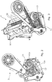
- FIGS 2 and 3 show a cracker roller assembly 7.
- the cracker roller assembly 7 comprises two frame parts 10 and 11 (not shown in Figure 2 ).
- Two cracker rollers 12 and 13, each formed from seventeen discs 30 mounted on respective roller shafts 12a, 13a, are mounted to a respective frame part 10, 11.
- the cracker roller discs 30 are provided with teeth for cracking/crushing the harvested crop which can be seen more clearly in Figures 6 and 11 .
- the cracker rollers 12, 13 are mounted parallel to each other and are rotatable about their longitudinal axes. A longitudinal space between the rollers, the roller gap, allows the cut crop to pass between the rollers.
- each of the discs 30, and the number of discs per roller may be varied.
- One factor affecting potential variation is the characteristics of the material to be harvested.
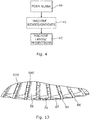
- the method of manufacture of the cracker roller discs 30 may be considered as a three-stage process, as represented by Figure 4 .
- the first stage 40 comprises forming a disc blank
- the second stage 41 comprises machining of ridges on the surfaces of that blank
- the third stage 42 comprises machining of peripheral features to create further cutting edges.
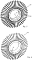
- Figures 5 and 6 respectively show perspective views of the disc blank 29 and machined disc 30.
- Figure 7 shows the disc blank 29 in plan view
- Figure 8 is a sectional view through the disc blank taken on line AA of Figure 7 .
- the blank has an axial bore 50 through the centre, a first portion 52 radially outward of the centre of substantially constant thickness, and a second portion 54 radially outward of the first portion which second portion tapers towards the periphery of the disc blank providing each of the second portions with a frusto-conical profile.
- a suitable taper angle is 21.8 degrees, although variation is possible as mentioned above.
- the disc blank 29 is a steel body which may be machined from a plain block of material but is preferably formed by forging.
- C45 steel is a suitable material, although other forgeable steels may be used instead.
- the forging process creates a plurality of upstanding ridges 56 extending radially outward across the second portion 54 on each face of the disc.
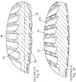
- Figures 9 and 10 are sectional views through the disc blank and the machined disc taken on line BB in Figure 8 . From Figure 9 it can be seen that the radial ridges 56 have a generally rounded profile in their upper (furthest from the disc body) portion. The lands 58, defined as the portions of disc surface between the ridges 56, are sloped from one ridge to the next to give a generally sawtooth profile.
- the disc blank 29 shown has 48 ridges of substantially constant width. It will be recognised that greater or fewer ridges may be provided, with the ridge height and separation being determined by the need to accommodate grain and other material of the particular crop being handled.
- the step of forming includes circumferentially aligning each ridge 56 on a first face of the disc blank 29 with a corresponding ridge on the opposing face of the disc blank. Furthermore, the step of forming includes aligning the distal ends of each corresponding pair of ridges 56 with radial projections 60 spaced around the periphery of the disc blank 29, as can be seen particularly in Figure 7 . Adjacent radial projections 60 are connected via a contour 61 which is inclined radially inwards in the direction of crop flow (indicated by arrow CF) to give a generally sawtooth profile in the direction of crop flow.
- the second stage 41 of the process comprises machining each of the opposed faces of the disc blank to remove the top part of each ridge 56 and leave at least one sharp edge 62 providing a cutting edge extending along each ridge
- this stage removes parts of the radial projections 60.
- the surface of the second portion 52 and the inner surface of the bore 50 may also be machined in this operation.
- the section view of Figure 10 shows one (upper) face of the disc having been machined to produce machined surfaces 64 and the edges 62.
- the second stage 41 is done by turning on a lathe, but may also be provided by milling in a radial direction.
- Figure 11 is a plan view of the machined disc 30, Figure 12 is a half section through the disc of Figure 11 taken on line CC, and Figure 13 is a part section through the disc of Figure 11 taken on line DD.
- the machined surfaces 64 include a conical (frusto-conical) machined surface 640 which extends radially along the ridges 56 and forms the outer contour of second portion 54.
- the conical machined surface 640 is further provided with a groove 650 which extends from the conical machined surface 640 towards the symmetry plane E1. Groove 650 radially extends along a spiral path (indicated with dotted line 651) and is substantially perpendicular to the ridges 56.
- the conical machined surface 640 provides edges 620 which are interrupted by groove 650 to form further edges described with the perspective view in Figure 14 .
- First groove edges 621 are formed by the intersection of the conical machined surface 640 and groove 650 and extend substantially perpendicular to edges 620.
- Second groove edges 622 extend at an angle to the edges 620 towards the towards the symmetry plane E1.
- third groove edges 623 which are formed substantially perpendicular to edges 620 and fourth groove edges 624 which are substantially parallel and offset to edges 620. It will be noted that the groove edges 621, 623 increase the number of edges by adding edges perpendicular to edges 620 while groove edges 622 and 624 extend the length off the overall edges provides.
- second groove edges 622 extend substantially perpendicular to edges 620 to form a rectangular cross section.
- second groove edges 622 may be provided in an angle to edges 620 to form a trapezoid cross section.
- the grove may be provided with a triangular cross section as indicated by dotted line 622". It will be recognised that the geometry of the grooves 650, 652a, 652b, 652c, 652d (depth, width, height and inclination of edges relative to each other) may vary depending on the need to accommodate grain and other material of the particular crop being handled, e.g. to avoid that crop kernels are trapped in the groove and not released from cracker roller assembly 7 so that crop flow would become blocked.
- the spiral groove 650 is provided which extends radially outwards in the direction of the crop flow indicted with arrow CF (REM: Please reverse the arrow in Figure 11 ) in Figure 11 to enable that crop trapped in groove 650 is pushed outwards.
- concentric grooves 652a, 652b, 652c, 652d may be provided , the path indicated with dotted line 653a to 653d concentric to the axis of rotation of disc 30 indicated with Axis A1.
- the forged ridges 56 are radially extending at a constant height relative to the lands 58.
- the ridges 56 may be provided with indentations 57 which match with the path of the grooves 650, 652a, 652b, 652c, 652d to be machined subsequently (indicated with dotted line 655) to reduce the material to be machined.
- the third stage 42 step of machining includes removing a portion of each radial projection 60 from either side of the disc blank and creating a machined area 70 of the lands 58.
- the machined area 70 is provided by a milling step whereby the milling cut is made at an angle inclined to the symmetry plane E1 shown in Figure 8 so that the machined surfaces 70 of the opposing faces theoretically meet in a sharp radial inclined edge 67. Due to tolerances, this radial inclined edge 67 may be interrupted, so that contour 61 is partly present as shown in Figure 11 with line 61a. This is not deleterious to the functioning of the disc.
- the design of ridges 56 is such that the machined surfaces 70 are of constant width so that, in order to create them, a milling tool with one diameter need only be moved once in between the ridges 56.
- the machined surfaces 64 respectively the conical machined surface 640, of each ridge meet in a sharp radial edge 66. All edges 66, 67, 620,621, 622, 623, 624 assist in the cutting of crop kernels together with leaves and stalk parts that have not been cleanly cut by the chopping drum 4 ( Fig. 1 ).
- a milling tool could be used to be moved along the ridges 56.
- the third stage 42 of the process is preferably accomplished on a milling machine. As will be recognised, it is a further particular benefit that all of the cutting edges 67 are provided by milling the machined surface 70 which extends only partly into the lands 58, so that time on the machining tool can be greatly reduced compared to prior art techniques.
- third stage 42 requires one-eighth of the conventional machining time as the movement of the machining tool is only 10 mm instead of 80 mm when machining the complete land 58.
- machining the complete land 58 would require a more complex pattern of movement of the tool as the machined surface would be more of a triangular shape, preventing the machining with a larger tool in the radially inward parts of the land 58.
- the second stage 41 and third stage 42 of the process are accomplished by using a milling machine in one step (one clamping required for each side), there is still a time saving due to the partial machining of land 58 to create machined surface 70.
- the second stage 41 may be split into two steps, a first step to machine the conical machined surface 640 and a subsequent step to machine grooves 650, 652a, 652b, 652c, 652d.
- machining means every kind of operation in which a cutting tool or the part itself is pivoted to cut contours from said part.
- the process of milling may include known milling techniques, e.g.
- grinding end grinding or plain grinding
- milling could also be used according to the procedures described for milling above, although this is not a preferred option due to the typically much higher costs involved.
- the above embodiment describes the disc blank as a forged part.
- any procedure to provide a disk blank e.g. steel casting and hardening afterwards, may be used instead.
- the second stage 41 and/or third stage 42 may require the usage of grinding. Even with such a method, the partial machining of lands 58 still results in a time saving.
- the cracker disc is made of a disc blank 29 which already contains pre-shaped ridges 56 and lands 58.
- current further technique may be used which comprises lathe turning of a blank of material to generate a disc shape and then milling the surface of the blank to cut in lands 58 to form ridges 56 with a conical machined surface 640 which extends radially along the ridges 56 and forms the outer contour of second portion 54.
- the conical machined surface 640 may then further provided with a groove 650 which extends from the conical machined surface 640 towards the symmetry plane E1.
- the present invention also provides a cracker roller 12, 13 made up of discs 30 manufactured as described above and mounted on a roller shaft 12a, 13a.
- a radially extending key or projection (not shown) from the shaft engages the keyway 68 to prevent the discs 30 rotating relative to the shaft.
Landscapes
- Life Sciences & Earth Sciences (AREA)
- Environmental Sciences (AREA)
- Engineering & Computer Science (AREA)
- Food Science & Technology (AREA)
- Milling Processes (AREA)
- Mechanical Engineering (AREA)
Abstract
Description
- This invention relates to a cracker roller assembly on a forage harvester or similar agricultural harvesting machine and, more specifically, to discs for use in such an assembly, to a method for the manufacture of such discs, and to discs produced by the method.
- Forage harvesters are used to harvest different kinds of crops which may require different harvesting processes. If, for example, grass is harvested the forage harvester cuts the grass from the field, compresses the grass in the compression rollers before chopping the harvested material into smaller parts in a chopper drum. The chopped grass is then discharged by a blower via a spout into an accompanying trailer. If, for example, a kernel crop such as maize, is harvested the harvesting process requires an additional step to crack the closed skin of the kernels, therefore, a cracker unit is provided between the chopper drum and the blower to crush each kernel.
- Cracker units typically comprise two longitudinal cracker rollers which are arranged with a roller gap (longitudinal space) between them through which harvested crop is fed. As shown in International Patent Application
WO 2012/010396 (commonly assigned with the present application) the cracker rollers may be formed by an arrangement of multiple cracker roller discs mounted on a common shaft. Another example is the disc cracker offered by Maschinenfabrik Bernard Krone GmbH (illustrated at http://landmaschinen.krone.de/index.php?id=2548&L=1). Such a multi-disc arrangement has a number of advantages compared to a unitary roller in terms of manufacturing and maintenance costs. For example, foreign object damage occasioned by a solid object passing through the roller gap may be remedied by the replacement of just a few of the discs rather than a complete, and much more expensive, roller. - Each disc typically has an arrangement of radial cutting surfaces across each face to assist in breaking up the material. With a large number (between 20 and 40) of discs in a typical cracker roller assembly, an efficient method of manufacture is clearly desirable. One current technique involves casting the individual discs followed by individual dressing of the cutting surfaces. An alternative technique comprises lathe turning of a blank of material to generate a disc shape and then milling the surface of the blank to cut in the individual cutting edges. Manufacture of cracker roller discs is discussed further in commonly-assigned European patent
EP-B-2666348 . - An object of the present invention is to provide an improved cracker roller disc.
- According to a first aspect of the present invention there is provided a cracker roller disc, having an axial bore through the centre, a first portion radially outward of the centre of substantially constant thickness, a second portion radially outward of the first portion which second portion tapers towards the periphery, and further comprising a plurality of conical machined surfaces forming radially extending edges on opposed faces of the disc;
characterised in that the edges are interrupted by grooves extending substantially perpendicular to said edges. - The grooves, which may be in the form of a spiral, a circle, or a series of concentric circles, extend the effective length of each edge and improve performance of the disc.
- In further aspects, the present invention provides a method of manufacturing the cracker roller disc, and cracker roller comprising a plurality of the discs axially aligned and mounted on a common shaft.
- Preferred features of the invention are set out in the dependent claims attached hereto and will be described below with reference to exemplary embodiments of the invention.
- The invention will now be described, by way of example only, with reference to the following drawings in which:
-
Figure 1 is a schematic view showing functional components of a forage harvester; -
Figures 2 and 3 show respectively end view and perspective view of the cracker unit ofFigure 1 ; -
Figure 4 is a flow chart representation of a method according to the invention; -
Figure 5 is a perspective view of a forged disc blank; -
Figure 6 is a perspective view of a machined disc; -
Figures 7 and 8 show respectively plan and sectional views of a forged disc blank; -
Figures 9 and 10 show sectional views through the disc blank at different stages in the manufacturing process; -
Figures 11, and 12 show respectively plan and half-sectional views of a finished cracker roller disc; -
Figure 13 is a sectional view through a part of the disc ofFigure 11 ; -
Figure 14 is a perspective view of a machined disc; -
Figure 15a, 15b are details of views ofFigure 12 ; -
Figure 16 is a plan view of a further embodiment of finished cracker roller disc; and -
Figure 17 is a half-sectional views of a forged roller disc. -
Figure 1 shows a forage harvester 1 provided with afront attachment 2 which contains cutting equipment for cutting a crop. The cut crop is fed through a series ofcompression rolls 3a in acompression roller housing 3 to achopper drum 4 where the crop is chopped into smaller pieces. The chopped crop passes throughduct 5 and is fed through thecracker unit 6 where the crop is further crushed and threshed. The harvested crop is then blown upwards alongduct 5 byaccelerator 8 and exits throughspout 9. InFigure 1 thecracker unit 6 is shown in an operational position: in a non-operational position, thecracker unit 6 is pivoted to the side of theduct 5 and therefore harvested crop by- passes thecracker roller assembly 7 as it moves throughduct 5. -
Figures 2 and 3 show acracker roller assembly 7. Thecracker roller assembly 7 comprises twoframe parts 10 and 11 (not shown inFigure 2 ). Twocracker rollers discs 30 mounted onrespective roller shafts respective frame part cracker roller discs 30 are provided with teeth for cracking/crushing the harvested crop which can be seen more clearly inFigures 6 and11 . Thecracker rollers - As will be understood, the dimensions of each of the
discs 30, and the number of discs per roller, may be varied. One factor affecting potential variation is the characteristics of the material to be harvested. - The method of manufacture of the
cracker roller discs 30 may be considered as a three-stage process, as represented byFigure 4 . Thefirst stage 40 comprises forming a disc blank, thesecond stage 41 comprises machining of ridges on the surfaces of that blank, and thethird stage 42 comprises machining of peripheral features to create further cutting edges. Each of these steps is described in more detail below. -
Figures 5 and 6 respectively show perspective views of the disc blank 29 and machineddisc 30.Figure 7 shows the disc blank 29 in plan view, andFigure 8 is a sectional view through the disc blank taken on line AA ofFigure 7 . The blank has anaxial bore 50 through the centre, afirst portion 52 radially outward of the centre of substantially constant thickness, and asecond portion 54 radially outward of the first portion which second portion tapers towards the periphery of the disc blank providing each of the second portions with a frusto-conical profile. A suitable taper angle is 21.8 degrees, although variation is possible as mentioned above. - The disc blank 29 is a steel body which may be machined from a plain block of material but is preferably formed by forging. C45 steel is a suitable material, although other forgeable steels may be used instead. As part of the blank forming step, the forging process creates a plurality of
upstanding ridges 56 extending radially outward across thesecond portion 54 on each face of the disc. -
Figures 9 and 10 are sectional views through the disc blank and the machined disc taken on line BB inFigure 8 . FromFigure 9 it can be seen that theradial ridges 56 have a generally rounded profile in their upper (furthest from the disc body) portion. Thelands 58, defined as the portions of disc surface between theridges 56, are sloped from one ridge to the next to give a generally sawtooth profile. The disc blank 29 shown has 48 ridges of substantially constant width. It will be recognised that greater or fewer ridges may be provided, with the ridge height and separation being determined by the need to accommodate grain and other material of the particular crop being handled. - As can be seen from
Figure 9 , the step of forming (first stage 40) includes circumferentially aligning eachridge 56 on a first face of the disc blank 29 with a corresponding ridge on the opposing face of the disc blank. Furthermore, the step of forming includes aligning the distal ends of each corresponding pair ofridges 56 withradial projections 60 spaced around the periphery of the disc blank 29, as can be seen particularly inFigure 7 . Adjacentradial projections 60 are connected via acontour 61 which is inclined radially inwards in the direction of crop flow (indicated by arrow CF) to give a generally sawtooth profile in the direction of crop flow. - Reverting to
Figure 4 , thesecond stage 41 of the process comprises machining each of the opposed faces of the disc blank to remove the top part of eachridge 56 and leave at least onesharp edge 62 providing a cutting edge extending along each ridge - Additionally, this stage removes parts of the
radial projections 60. The surface of thesecond portion 52 and the inner surface of thebore 50 may also be machined in this operation. The section view ofFigure 10 shows one (upper) face of the disc having been machined to produce machinedsurfaces 64 and theedges 62. Preferably thesecond stage 41 is done by turning on a lathe, but may also be provided by milling in a radial direction. -
Figure 11 is a plan view of the machineddisc 30,Figure 12 is a half section through the disc ofFigure 11 taken on line CC, andFigure 13 is a part section through the disc ofFigure 11 taken on line DD. As best seen inFigures 10 and11 , themachined surfaces 64 include a conical (frusto-conical) machinedsurface 640 which extends radially along theridges 56 and forms the outer contour ofsecond portion 54. - The conical machined
surface 640 is further provided with agroove 650 which extends from the conical machinedsurface 640 towards the symmetry plane E1. Groove 650 radially extends along a spiral path (indicated with dotted line 651) and is substantially perpendicular to theridges 56. - In this way, the conical machined
surface 640 providesedges 620 which are interrupted bygroove 650 to form further edges described with the perspective view inFigure 14 . - First groove edges 621 are formed by the intersection of the conical machined
surface 640 and groove 650 and extend substantially perpendicular to edges 620. Second groove edges 622 extend at an angle to theedges 620 towards the towards the symmetry plane E1. At the grove base third groove edges 623 which are formed substantially perpendicular toedges 620 and fourth groove edges 624 which are substantially parallel and offset to edges 620. It will be noted that the groove edges 621, 623 increase the number of edges by adding edges perpendicular toedges 620 while groove edges 622 and 624 extend the length off the overall edges provides. - In the shown embodiment and further indicated with
Figure 15a , second groove edges 622 extend substantially perpendicular toedges 620 to form a rectangular cross section. Alternatively and as best seen inFigure 15b , second groove edges 622 may be provided in an angle toedges 620 to form a trapezoid cross section. More alternatively, the grove may be provided with a triangular cross section as indicated bydotted line 622". It will be recognised that the geometry of thegrooves cracker roller assembly 7 so that crop flow would become blocked. - In the shown embodiment of
Figure 11 , thespiral groove 650 is provided which extends radially outwards in the direction of the crop flow indicted with arrow CF (REM: Please reverse the arrow inFigure 11 ) inFigure 11 to enable that crop trapped ingroove 650 is pushed outwards. Alternatively and shown inFigure 16 ,concentric grooves line 653a to 653d concentric to the axis of rotation ofdisc 30 indicated with Axis A1. - In the shown embodiment of
Figure 7 and 8 , the forgedridges 56 are radially extending at a constant height relative to thelands 58. Alternatively, as shown inFigure 17 , theridges 56 may be provided withindentations 57 which match with the path of thegrooves - Comparing particularly
Figures 7 ,11 and13 , it can be seen that thethird stage 42 step of machining includes removing a portion of eachradial projection 60 from either side of the disc blank and creating a machinedarea 70 of thelands 58. The machinedarea 70 is provided by a milling step whereby the milling cut is made at an angle inclined to the symmetry plane E1 shown inFigure 8 so that themachined surfaces 70 of the opposing faces theoretically meet in a sharp radialinclined edge 67. Due to tolerances, this radial inclinededge 67 may be interrupted, so thatcontour 61 is partly present as shown inFigure 11 withline 61a. This is not deleterious to the functioning of the disc. - In the illustrated embodiment, the design of
ridges 56 is such that themachined surfaces 70 are of constant width so that, in order to create them, a milling tool with one diameter need only be moved once in between theridges 56. - As can be seen in
Figures 11 to 13 , the machined surfaces 64, respectively the conical machinedsurface 640, of each ridge meet in a sharpradial edge 66. All edges 66, 67, 620,621, 622, 623, 624 assist in the cutting of crop kernels together with leaves and stalk parts that have not been cleanly cut by the chopping drum 4 (Fig. 1 ). - This is preferably accomplished by turning the disc blank 29 in a
second stage 41 of the process on a lathe using a single cutting tool to remove the upper part of allridges 56 andperipheral portions 60 on a first side of the disc blank in a single turning operation, before reversing the disc blank on the lathe and machining the second side. Alternatively, a milling tool could be used to be moved along theridges 56. - The
third stage 42 of the process is preferably accomplished on a milling machine. As will be recognised, it is a further particular benefit that all of the cutting edges 67 are provided by milling the machinedsurface 70 which extends only partly into thelands 58, so that time on the machining tool can be greatly reduced compared to prior art techniques. In the embodiment shown,third stage 42 requires one-eighth of the conventional machining time as the movement of the machining tool is only 10 mm instead of 80 mm when machining thecomplete land 58. Furthermore, machining thecomplete land 58 would require a more complex pattern of movement of the tool as the machined surface would be more of a triangular shape, preventing the machining with a larger tool in the radially inward parts of theland 58. - If the
second stage 41 andthird stage 42 of the process are accomplished by using a milling machine in one step (one clamping required for each side), there is still a time saving due to the partial machining ofland 58 to create machinedsurface 70. Alternatively thesecond stage 41 may be split into two steps, a first step to machine the conical machinedsurface 640 and a subsequent step tomachine grooves - Furthermore, if using a lathe to carry out the
second stage 41 it may be possible to effect thethird stage 42 on the same machinery if the lathe is equipped with driven tools and positionable (milling) spindle. - As used herein in relation to the invention, the term "machining" means every kind of operation in which a cutting tool or the part itself is pivoted to cut contours from said part.
- The process of milling may include known milling techniques, e.g.
- End/Face milling: characterised in that the tool penetrates the part along its rotational axis whereby the end face can be completely used to cut the part. In the case of
stage 41, the machinedsurface 64 is approximately perpendicular to the rotational axis of the milling tool. - Cylindrical or plain/peripheral milling: characterised in that the tool penetrates the part perpendicular to its rotational axis whereby the circumferential face can be completely used to cut the part. In the case of
stage 41, the machinedsurface 64 is approximately parallel to the rotational axis of the milling tool. - Furthermore, grinding (end grinding or plain grinding) could also be used according to the procedures described for milling above, although this is not a preferred option due to the typically much higher costs involved.
- Referring to the
first stage 40, the above embodiment describes the disc blank as a forged part. However, it will be understood that any procedure to provide a disk blank, e.g. steel casting and hardening afterwards, may be used instead. In such a case, thesecond stage 41 and/orthird stage 42 may require the usage of grinding. Even with such a method, the partial machining oflands 58 still results in a time saving. - In the shown embodiment, the cracker disc is made of a disc blank 29 which already contains
pre-shaped ridges 56 and lands 58. Alternatively, current further technique may be used which comprises lathe turning of a blank of material to generate a disc shape and then milling the surface of the blank to cut inlands 58 to formridges 56 with a conical machinedsurface 640 which extends radially along theridges 56 and forms the outer contour ofsecond portion 54. The conical machinedsurface 640 may then further provided with agroove 650 which extends from the conical machinedsurface 640 towards the symmetry plane E1. - Referring back to
Figure 3 , the present invention also provides acracker roller discs 30 manufactured as described above and mounted on aroller shaft axially extending keyway 68 is cut in the wall of thebore 50 through the disc blank: when mounted on aroller shaft keyway 68 to prevent thediscs 30 rotating relative to the shaft. - From reading of the present disclosure, other modifications will be apparent to those skilled in the art and the scope of the invention is limited only by the following claims.
Claims (11)
- A cracker roller disc, having an axial bore through the centre, a first portion radially outward of the centre of substantially constant thickness, a second portion radially outward of the first portion which second portion tapers towards the periphery, and further comprising a plurality of conical machined surfaces (640) forming radially extending edges (620) on opposed faces of the disc;
characterised in that the edges (620) are interrupted by grooves (650, 652a, 652b, 652c, 652d) extending substantially perpendicular to said edges (620). - A cracker roller disc according claim 1 wherein the grooves (650) on opposed faces of the disc extend on a spiral path
- A cracker roller disc according claim 1 wherein a plurality of grooves (652a, 652b, 652c, 652d) on opposed faces of the disc extend on a concentric path with reference to axis of rotation of the disc.
- A cracker roller disc according to any of claims 1 to 3 wherein the grooves (650, 652a, 652b, 652c, 652d) are provided with a rectangular or trapezoid or triangular section.
- A method of manufacturing a cracker roller disc, comprising:in a first stage (40) forming a disc blank having an axial bore through the centre, a first portion radially outward of the centre of substantially constant thickness, a second portion radially outward of the first portion whereby the second portion tapers towards the periphery of the disc blank, the disc blank further having a plurality of upstanding ridges extending radially outward across the second portion on opposed faces of the disc; andin a second stage (41) forming at least one groove in each second portion,wherein each groove is substantially perpendicular to each of the ridges.
- A method as claimed in claim 5, wherein the at least one groove extends on a spiral path about the axis of rotation in use of the disc.
- A method as claimed in claim 5, having two or more circular grooves of different respective radii in each second portion, said grooves being concentrically arranged about the axis of rotation in use of the disc.
- A method as claimed in any of Claims 5 to 7, wherein the disc blank is steel and the first stage (40) comprises forging the disc blank.
- A method as claimed in claim 8, wherein the disc blank is forged with indentations corresponding to the at least one groove in its surface.
- A cracker roller disc produced by a method according to any of Claims 5 to 9.
- A cracker roller comprising a plurality of discs as claimed in any of Claims 1 to 4 or 10, axially aligned and mounted on a common shaft.
Applications Claiming Priority (1)
| Application Number | Priority Date | Filing Date | Title |
|---|---|---|---|
| GBGB1917622.1A GB201917622D0 (en) | 2019-12-03 | 2019-12-03 | Cracker roller disc |
Publications (2)
| Publication Number | Publication Date |
|---|---|
| EP3831188A1 true EP3831188A1 (en) | 2021-06-09 |
| EP3831188B1 EP3831188B1 (en) | 2023-04-05 |
Family
ID=69147018
Family Applications (1)
| Application Number | Title | Priority Date | Filing Date |
|---|---|---|---|
| EP20210888.2A Active EP3831188B1 (en) | 2019-12-03 | 2020-12-01 | Cracker roller disc |
Country Status (3)
| Country | Link |
|---|---|
| US (1) | US11758851B2 (en) |
| EP (1) | EP3831188B1 (en) |
| GB (1) | GB201917622D0 (en) |
Families Citing this family (2)
| Publication number | Priority date | Publication date | Assignee | Title |
|---|---|---|---|---|
| CN113558460B (en) * | 2021-09-24 | 2022-05-10 | 邳州舜邦生物科技有限公司 | A mashing device for garlic paste production and processing |
| DE102022110680A1 (en) * | 2022-05-02 | 2023-11-02 | ZIEMANN HOLVRIEKA GmbH | Disc arrangement and grinder for a mill, use of the same for crushing a ground material |
Citations (5)
| Publication number | Priority date | Publication date | Assignee | Title |
|---|---|---|---|---|
| WO2012010396A1 (en) | 2010-07-22 | 2012-01-26 | Agco International Gmbh | Cracker roller assembly |
| DE102012000974A1 (en) * | 2012-01-20 | 2013-07-25 | Innova 6. Beteiligungsgesellschaft Mbh | Crushing plate of comminuting device for crushing crops, has notch in outer surface, which is provided at specific angle obliquely with respect to the local radius |
| DE102013104587A1 (en) * | 2013-05-06 | 2014-11-06 | Kurz Tribotechnik Gmbh & Co. Kg | Profiled comminution disc, crushing roller and shredder for harvesters |
| DE202015007502U1 (en) * | 2015-10-29 | 2016-01-19 | Markus Hüter | Comminution disc for a comminution device for bulk material particles and comminution plate having such comminution discs |
| EP2666348B1 (en) | 2012-05-24 | 2018-07-04 | AGCO International GmbH | Cracker roller disc |
Family Cites Families (11)
| Publication number | Priority date | Publication date | Assignee | Title |
|---|---|---|---|---|
| US329729A (en) * | 1885-11-03 | Grinding-mill for reduci ng grain | ||
| US2713277A (en) | 1950-09-02 | 1955-07-19 | Mullins Mfg Corp | Method of cold forming ring gears |
| DE4122338A1 (en) * | 1991-07-05 | 1993-01-14 | Land Technik Ag Schoenebeck | REDUCTION DEVICE FOR FIELD CHOPPER |
| DE102004026068B3 (en) * | 2004-05-25 | 2006-02-09 | Martin Rothmann | Crushing device for bulk material particles |
| DE102005053092A1 (en) * | 2005-11-04 | 2007-05-10 | Lacotec Agri Systems Gmbh | Crushing device for crops |
| DE102011052795A1 (en) * | 2010-08-19 | 2012-02-23 | Leibniz-Institut für Agrartechnik Potsdam-Bornim e.V. | Comminution device for free-flowing e.g. grains for feeding animals, has wedge surfaces including profiles that run between outer periphery and inner periphery of one wedge surface |
| DE102010046183A1 (en) * | 2010-09-23 | 2012-03-29 | Innova 6. Beteiligungsgesellschaft Mbh | Device for comminution of ensiled material such as wet corn, has crushing rollers that include disk elements which are arranged on axis and wave-like structure that is provided on surface of disk element |
| US9486806B1 (en) * | 2011-04-01 | 2016-11-08 | Claas Saulgau Gmbh | System and method for processing crop materials into livestock feed and the product thereof |
| US9833785B2 (en) | 2012-12-17 | 2017-12-05 | Kooima Company | Method of making a processor disk |
| US9918432B2 (en) * | 2015-07-02 | 2018-03-20 | Horning Manufacturing, LLC | Corn processing roll with chevron grooves |
| JP7425791B2 (en) * | 2018-10-11 | 2024-01-31 | アンドリッツ インコーポレーテッド | Refiner plate with inter-bar wear ridges |
-
2019
- 2019-12-03 GB GBGB1917622.1A patent/GB201917622D0/en not_active Ceased
-
2020
- 2020-12-01 EP EP20210888.2A patent/EP3831188B1/en active Active
- 2020-12-03 US US17/110,737 patent/US11758851B2/en active Active
Patent Citations (5)
| Publication number | Priority date | Publication date | Assignee | Title |
|---|---|---|---|---|
| WO2012010396A1 (en) | 2010-07-22 | 2012-01-26 | Agco International Gmbh | Cracker roller assembly |
| DE102012000974A1 (en) * | 2012-01-20 | 2013-07-25 | Innova 6. Beteiligungsgesellschaft Mbh | Crushing plate of comminuting device for crushing crops, has notch in outer surface, which is provided at specific angle obliquely with respect to the local radius |
| EP2666348B1 (en) | 2012-05-24 | 2018-07-04 | AGCO International GmbH | Cracker roller disc |
| DE102013104587A1 (en) * | 2013-05-06 | 2014-11-06 | Kurz Tribotechnik Gmbh & Co. Kg | Profiled comminution disc, crushing roller and shredder for harvesters |
| DE202015007502U1 (en) * | 2015-10-29 | 2016-01-19 | Markus Hüter | Comminution disc for a comminution device for bulk material particles and comminution plate having such comminution discs |
Also Published As
| Publication number | Publication date |
|---|---|
| US20210161073A1 (en) | 2021-06-03 |
| US11758851B2 (en) | 2023-09-19 |
| GB201917622D0 (en) | 2020-01-15 |
| EP3831188B1 (en) | 2023-04-05 |
Similar Documents
| Publication | Publication Date | Title |
|---|---|---|
| EP2666348B1 (en) | Cracker roller disc | |
| EP3831188B1 (en) | Cracker roller disc | |
| US5404699A (en) | Knife edged stalk rolls | |
| US8464505B1 (en) | Stalk roll | |
| EP3586599B1 (en) | Corn stalk roll arrangement | |
| RU2415712C2 (en) | Roll for corn stalk, corn stalk reeper and appropriate machine for corn stalk | |
| US4365462A (en) | Mower having separately replaceable bearing subassembly | |
| BE1021740B1 (en) | KNIFE CARRIER FOR A CHICKEN DRUM AND CHICKEN DRUM FOR A FIELD CHOPPER | |
| WO2017223051A4 (en) | Harvester | |
| AU2012244390A1 (en) | Sugar cane chopper blade | |
| WO2017023851A1 (en) | Stalk roll | |
| US12029164B2 (en) | Stalk roll with multiple flutes of different lengths | |
| EP2912935A1 (en) | Blade rotor for a mowing apparatus and mowing apparatus with same | |
| EP3401048B1 (en) | Saw blade for a saw for cutting stemular stalks | |
| DE10108505B4 (en) | Machine for mowing stalk-like crops | |
| AU2022231744A1 (en) | Sugarcane harvester extractor with leaf shredder | |
| US20140182256A1 (en) | Device for mowing | |
| DE202009000431U1 (en) | Crushing disc, crushing roller and shredder for harvesters | |
| EP4338578A1 (en) | Threshing drum for a threshing device of a combine harvester and combine harvester | |
| EP1000533B1 (en) | Picking device for harvesting cereals | |
| RU2340157C1 (en) | Machine for harvesting of row crops, predominantly soya beans | |
| SE542323C2 (en) | Plate tools, agricultural implements comprising such a plate tool and a procedure for the manufacture of plate tools | |
| RU2651601C2 (en) | Device for regrinding and agricultural harvesting machine | |
| AU2003204322A1 (en) | Improved method and apparatus for cane cutting | |
| RU2648054C2 (en) | Grinding device |
Legal Events
| Date | Code | Title | Description |
|---|---|---|---|
| PUAI | Public reference made under article 153(3) epc to a published international application that has entered the european phase |
Free format text: ORIGINAL CODE: 0009012 |
|
| STAA | Information on the status of an ep patent application or granted ep patent |
Free format text: STATUS: THE APPLICATION HAS BEEN PUBLISHED |
|
| AK | Designated contracting states |
Kind code of ref document: A1 Designated state(s): AL AT BE BG CH CY CZ DE DK EE ES FI FR GB GR HR HU IE IS IT LI LT LU LV MC MK MT NL NO PL PT RO RS SE SI SK SM TR |
|
| STAA | Information on the status of an ep patent application or granted ep patent |
Free format text: STATUS: REQUEST FOR EXAMINATION WAS MADE |
|
| 17P | Request for examination filed |
Effective date: 20211209 |
|
| RBV | Designated contracting states (corrected) |
Designated state(s): AL AT BE BG CH CY CZ DE DK EE ES FI FR GB GR HR HU IE IS IT LI LT LU LV MC MK MT NL NO PL PT RO RS SE SI SK SM TR |
|
| GRAP | Despatch of communication of intention to grant a patent |
Free format text: ORIGINAL CODE: EPIDOSNIGR1 |
|
| STAA | Information on the status of an ep patent application or granted ep patent |
Free format text: STATUS: GRANT OF PATENT IS INTENDED |
|
| INTG | Intention to grant announced |
Effective date: 20221219 |
|
| GRAS | Grant fee paid |
Free format text: ORIGINAL CODE: EPIDOSNIGR3 |
|
| GRAA | (expected) grant |
Free format text: ORIGINAL CODE: 0009210 |
|
| STAA | Information on the status of an ep patent application or granted ep patent |
Free format text: STATUS: THE PATENT HAS BEEN GRANTED |
|
| AK | Designated contracting states |
Kind code of ref document: B1 Designated state(s): AL AT BE BG CH CY CZ DE DK EE ES FI FR GB GR HR HU IE IS IT LI LT LU LV MC MK MT NL NO PL PT RO RS SE SI SK SM TR |
|
| REG | Reference to a national code |
Ref country code: GB Ref legal event code: FG4D |
|
| REG | Reference to a national code |
Ref country code: CH Ref legal event code: EP |
|
| REG | Reference to a national code |
Ref country code: AT Ref legal event code: REF Ref document number: 1557580 Country of ref document: AT Kind code of ref document: T Effective date: 20230415 |
|
| REG | Reference to a national code |
Ref country code: DE Ref legal event code: R096 Ref document number: 602020009438 Country of ref document: DE |
|
| REG | Reference to a national code |
Ref country code: IE Ref legal event code: FG4D |
|
| REG | Reference to a national code |
Ref country code: LT Ref legal event code: MG9D |
|
| REG | Reference to a national code |
Ref country code: NL Ref legal event code: MP Effective date: 20230405 |
|
| REG | Reference to a national code |
Ref country code: AT Ref legal event code: MK05 Ref document number: 1557580 Country of ref document: AT Kind code of ref document: T Effective date: 20230405 |
|
| PG25 | Lapsed in a contracting state [announced via postgrant information from national office to epo] |
Ref country code: NL Free format text: LAPSE BECAUSE OF FAILURE TO SUBMIT A TRANSLATION OF THE DESCRIPTION OR TO PAY THE FEE WITHIN THE PRESCRIBED TIME-LIMIT Effective date: 20230405 |
|
| PG25 | Lapsed in a contracting state [announced via postgrant information from national office to epo] |
Ref country code: SE Free format text: LAPSE BECAUSE OF FAILURE TO SUBMIT A TRANSLATION OF THE DESCRIPTION OR TO PAY THE FEE WITHIN THE PRESCRIBED TIME-LIMIT Effective date: 20230405 Ref country code: PT Free format text: LAPSE BECAUSE OF FAILURE TO SUBMIT A TRANSLATION OF THE DESCRIPTION OR TO PAY THE FEE WITHIN THE PRESCRIBED TIME-LIMIT Effective date: 20230807 Ref country code: NO Free format text: LAPSE BECAUSE OF FAILURE TO SUBMIT A TRANSLATION OF THE DESCRIPTION OR TO PAY THE FEE WITHIN THE PRESCRIBED TIME-LIMIT Effective date: 20230705 Ref country code: ES Free format text: LAPSE BECAUSE OF FAILURE TO SUBMIT A TRANSLATION OF THE DESCRIPTION OR TO PAY THE FEE WITHIN THE PRESCRIBED TIME-LIMIT Effective date: 20230405 Ref country code: AT Free format text: LAPSE BECAUSE OF FAILURE TO SUBMIT A TRANSLATION OF THE DESCRIPTION OR TO PAY THE FEE WITHIN THE PRESCRIBED TIME-LIMIT Effective date: 20230405 |
|
| PG25 | Lapsed in a contracting state [announced via postgrant information from national office to epo] |
Ref country code: RS Free format text: LAPSE BECAUSE OF FAILURE TO SUBMIT A TRANSLATION OF THE DESCRIPTION OR TO PAY THE FEE WITHIN THE PRESCRIBED TIME-LIMIT Effective date: 20230405 Ref country code: PL Free format text: LAPSE BECAUSE OF FAILURE TO SUBMIT A TRANSLATION OF THE DESCRIPTION OR TO PAY THE FEE WITHIN THE PRESCRIBED TIME-LIMIT Effective date: 20230405 Ref country code: LV Free format text: LAPSE BECAUSE OF FAILURE TO SUBMIT A TRANSLATION OF THE DESCRIPTION OR TO PAY THE FEE WITHIN THE PRESCRIBED TIME-LIMIT Effective date: 20230405 Ref country code: LT Free format text: LAPSE BECAUSE OF FAILURE TO SUBMIT A TRANSLATION OF THE DESCRIPTION OR TO PAY THE FEE WITHIN THE PRESCRIBED TIME-LIMIT Effective date: 20230405 Ref country code: IS Free format text: LAPSE BECAUSE OF FAILURE TO SUBMIT A TRANSLATION OF THE DESCRIPTION OR TO PAY THE FEE WITHIN THE PRESCRIBED TIME-LIMIT Effective date: 20230805 Ref country code: HR Free format text: LAPSE BECAUSE OF FAILURE TO SUBMIT A TRANSLATION OF THE DESCRIPTION OR TO PAY THE FEE WITHIN THE PRESCRIBED TIME-LIMIT Effective date: 20230405 Ref country code: GR Free format text: LAPSE BECAUSE OF FAILURE TO SUBMIT A TRANSLATION OF THE DESCRIPTION OR TO PAY THE FEE WITHIN THE PRESCRIBED TIME-LIMIT Effective date: 20230706 Ref country code: AL Free format text: LAPSE BECAUSE OF FAILURE TO SUBMIT A TRANSLATION OF THE DESCRIPTION OR TO PAY THE FEE WITHIN THE PRESCRIBED TIME-LIMIT Effective date: 20230405 |
|
| PG25 | Lapsed in a contracting state [announced via postgrant information from national office to epo] |
Ref country code: FI Free format text: LAPSE BECAUSE OF FAILURE TO SUBMIT A TRANSLATION OF THE DESCRIPTION OR TO PAY THE FEE WITHIN THE PRESCRIBED TIME-LIMIT Effective date: 20230405 |
|
| REG | Reference to a national code |
Ref country code: DE Ref legal event code: R097 Ref document number: 602020009438 Country of ref document: DE |
|
| PG25 | Lapsed in a contracting state [announced via postgrant information from national office to epo] |
Ref country code: SK Free format text: LAPSE BECAUSE OF FAILURE TO SUBMIT A TRANSLATION OF THE DESCRIPTION OR TO PAY THE FEE WITHIN THE PRESCRIBED TIME-LIMIT Effective date: 20230405 |
|
| PG25 | Lapsed in a contracting state [announced via postgrant information from national office to epo] |
Ref country code: SM Free format text: LAPSE BECAUSE OF FAILURE TO SUBMIT A TRANSLATION OF THE DESCRIPTION OR TO PAY THE FEE WITHIN THE PRESCRIBED TIME-LIMIT Effective date: 20230405 Ref country code: SK Free format text: LAPSE BECAUSE OF FAILURE TO SUBMIT A TRANSLATION OF THE DESCRIPTION OR TO PAY THE FEE WITHIN THE PRESCRIBED TIME-LIMIT Effective date: 20230405 Ref country code: RO Free format text: LAPSE BECAUSE OF FAILURE TO SUBMIT A TRANSLATION OF THE DESCRIPTION OR TO PAY THE FEE WITHIN THE PRESCRIBED TIME-LIMIT Effective date: 20230405 Ref country code: EE Free format text: LAPSE BECAUSE OF FAILURE TO SUBMIT A TRANSLATION OF THE DESCRIPTION OR TO PAY THE FEE WITHIN THE PRESCRIBED TIME-LIMIT Effective date: 20230405 Ref country code: DK Free format text: LAPSE BECAUSE OF FAILURE TO SUBMIT A TRANSLATION OF THE DESCRIPTION OR TO PAY THE FEE WITHIN THE PRESCRIBED TIME-LIMIT Effective date: 20230405 Ref country code: CZ Free format text: LAPSE BECAUSE OF FAILURE TO SUBMIT A TRANSLATION OF THE DESCRIPTION OR TO PAY THE FEE WITHIN THE PRESCRIBED TIME-LIMIT Effective date: 20230405 |
|
| PGFP | Annual fee paid to national office [announced via postgrant information from national office to epo] |
Ref country code: FR Payment date: 20231222 Year of fee payment: 4 |
|
| PLBE | No opposition filed within time limit |
Free format text: ORIGINAL CODE: 0009261 |
|
| STAA | Information on the status of an ep patent application or granted ep patent |
Free format text: STATUS: NO OPPOSITION FILED WITHIN TIME LIMIT |
|
| 26N | No opposition filed |
Effective date: 20240108 |
|
| PG25 | Lapsed in a contracting state [announced via postgrant information from national office to epo] |
Ref country code: SI Free format text: LAPSE BECAUSE OF FAILURE TO SUBMIT A TRANSLATION OF THE DESCRIPTION OR TO PAY THE FEE WITHIN THE PRESCRIBED TIME-LIMIT Effective date: 20230405 |
|
| PG25 | Lapsed in a contracting state [announced via postgrant information from national office to epo] |
Ref country code: SI Free format text: LAPSE BECAUSE OF FAILURE TO SUBMIT A TRANSLATION OF THE DESCRIPTION OR TO PAY THE FEE WITHIN THE PRESCRIBED TIME-LIMIT Effective date: 20230405 Ref country code: IT Free format text: LAPSE BECAUSE OF FAILURE TO SUBMIT A TRANSLATION OF THE DESCRIPTION OR TO PAY THE FEE WITHIN THE PRESCRIBED TIME-LIMIT Effective date: 20230405 |
|
| REG | Reference to a national code |
Ref country code: CH Ref legal event code: PL |
|
| PG25 | Lapsed in a contracting state [announced via postgrant information from national office to epo] |
Ref country code: LU Free format text: LAPSE BECAUSE OF NON-PAYMENT OF DUE FEES Effective date: 20231201 |
|
| PG25 | Lapsed in a contracting state [announced via postgrant information from national office to epo] |
Ref country code: MC Free format text: LAPSE BECAUSE OF FAILURE TO SUBMIT A TRANSLATION OF THE DESCRIPTION OR TO PAY THE FEE WITHIN THE PRESCRIBED TIME-LIMIT Effective date: 20230405 |
|
| PG25 | Lapsed in a contracting state [announced via postgrant information from national office to epo] |
Ref country code: MC Free format text: LAPSE BECAUSE OF FAILURE TO SUBMIT A TRANSLATION OF THE DESCRIPTION OR TO PAY THE FEE WITHIN THE PRESCRIBED TIME-LIMIT Effective date: 20230405 Ref country code: LU Free format text: LAPSE BECAUSE OF NON-PAYMENT OF DUE FEES Effective date: 20231201 |
|
| REG | Reference to a national code |
Ref country code: IE Ref legal event code: MM4A |
|
| PG25 | Lapsed in a contracting state [announced via postgrant information from national office to epo] |
Ref country code: IE Free format text: LAPSE BECAUSE OF NON-PAYMENT OF DUE FEES Effective date: 20231201 |
|
| PG25 | Lapsed in a contracting state [announced via postgrant information from national office to epo] |
Ref country code: CH Free format text: LAPSE BECAUSE OF NON-PAYMENT OF DUE FEES Effective date: 20231231 |
|
| PG25 | Lapsed in a contracting state [announced via postgrant information from national office to epo] |
Ref country code: IE Free format text: LAPSE BECAUSE OF NON-PAYMENT OF DUE FEES Effective date: 20231201 Ref country code: CH Free format text: LAPSE BECAUSE OF NON-PAYMENT OF DUE FEES Effective date: 20231231 |
|
| PG25 | Lapsed in a contracting state [announced via postgrant information from national office to epo] |
Ref country code: BG Free format text: LAPSE BECAUSE OF FAILURE TO SUBMIT A TRANSLATION OF THE DESCRIPTION OR TO PAY THE FEE WITHIN THE PRESCRIBED TIME-LIMIT Effective date: 20230405 |
|
| PG25 | Lapsed in a contracting state [announced via postgrant information from national office to epo] |
Ref country code: BG Free format text: LAPSE BECAUSE OF FAILURE TO SUBMIT A TRANSLATION OF THE DESCRIPTION OR TO PAY THE FEE WITHIN THE PRESCRIBED TIME-LIMIT Effective date: 20230405 |
|
| PG25 | Lapsed in a contracting state [announced via postgrant information from national office to epo] |
Ref country code: CY Free format text: LAPSE BECAUSE OF FAILURE TO SUBMIT A TRANSLATION OF THE DESCRIPTION OR TO PAY THE FEE WITHIN THE PRESCRIBED TIME-LIMIT; INVALID AB INITIO Effective date: 20201201 |
|
| PG25 | Lapsed in a contracting state [announced via postgrant information from national office to epo] |
Ref country code: HU Free format text: LAPSE BECAUSE OF FAILURE TO SUBMIT A TRANSLATION OF THE DESCRIPTION OR TO PAY THE FEE WITHIN THE PRESCRIBED TIME-LIMIT; INVALID AB INITIO Effective date: 20201201 |
|
| GBPC | Gb: european patent ceased through non-payment of renewal fee |
Effective date: 20241201 |
|
| PG25 | Lapsed in a contracting state [announced via postgrant information from national office to epo] |
Ref country code: GB Free format text: LAPSE BECAUSE OF NON-PAYMENT OF DUE FEES Effective date: 20241201 |
|
| PG25 | Lapsed in a contracting state [announced via postgrant information from national office to epo] |
Ref country code: FR Free format text: LAPSE BECAUSE OF NON-PAYMENT OF DUE FEES Effective date: 20241231 |
|
| PG25 | Lapsed in a contracting state [announced via postgrant information from national office to epo] |
Ref country code: TR Free format text: LAPSE BECAUSE OF FAILURE TO SUBMIT A TRANSLATION OF THE DESCRIPTION OR TO PAY THE FEE WITHIN THE PRESCRIBED TIME-LIMIT Effective date: 20230405 |
|
| PGFP | Annual fee paid to national office [announced via postgrant information from national office to epo] |
Ref country code: DE Payment date: 20251211 Year of fee payment: 6 |
|
| PGFP | Annual fee paid to national office [announced via postgrant information from national office to epo] |
Ref country code: BE Payment date: 20251219 Year of fee payment: 6 |