EP3830401B1 - Échangeur thermique pour turbomachine - Google Patents
Échangeur thermique pour turbomachine Download PDFInfo
- Publication number
- EP3830401B1 EP3830401B1 EP19765528.5A EP19765528A EP3830401B1 EP 3830401 B1 EP3830401 B1 EP 3830401B1 EP 19765528 A EP19765528 A EP 19765528A EP 3830401 B1 EP3830401 B1 EP 3830401B1
- Authority
- EP
- European Patent Office
- Prior art keywords
- circuit
- conduit
- annular part
- annular
- heat exchanger
- Prior art date
- Legal status (The legal status is an assumption and is not a legal conclusion. Google has not performed a legal analysis and makes no representation as to the accuracy of the status listed.)
- Active
Links
Images



Classifications
-
- F—MECHANICAL ENGINEERING; LIGHTING; HEATING; WEAPONS; BLASTING
- F02—COMBUSTION ENGINES; HOT-GAS OR COMBUSTION-PRODUCT ENGINE PLANTS
- F02C—GAS-TURBINE PLANTS; AIR INTAKES FOR JET-PROPULSION PLANTS; CONTROLLING FUEL SUPPLY IN AIR-BREATHING JET-PROPULSION PLANTS
- F02C7/00—Features, components parts, details or accessories, not provided for in, or of interest apart form groups F02C1/00 - F02C6/00; Air intakes for jet-propulsion plants
- F02C7/12—Cooling of plants
- F02C7/14—Cooling of plants of fluids in the plant, e.g. lubricant or fuel
-
- F—MECHANICAL ENGINEERING; LIGHTING; HEATING; WEAPONS; BLASTING
- F28—HEAT EXCHANGE IN GENERAL
- F28D—HEAT-EXCHANGE APPARATUS, NOT PROVIDED FOR IN ANOTHER SUBCLASS, IN WHICH THE HEAT-EXCHANGE MEDIA DO NOT COME INTO DIRECT CONTACT
- F28D9/00—Heat-exchange apparatus having stationary plate-like or laminated conduit assemblies for both heat-exchange media, the media being in contact with different sides of a conduit wall
-
- F—MECHANICAL ENGINEERING; LIGHTING; HEATING; WEAPONS; BLASTING
- F28—HEAT EXCHANGE IN GENERAL
- F28F—DETAILS OF HEAT-EXCHANGE AND HEAT-TRANSFER APPARATUS, OF GENERAL APPLICATION
- F28F3/00—Plate-like or laminated elements; Assemblies of plate-like or laminated elements
- F28F3/12—Elements constructed in the shape of a hollow panel, e.g. with channels
-
- F—MECHANICAL ENGINEERING; LIGHTING; HEATING; WEAPONS; BLASTING
- F05—INDEXING SCHEMES RELATING TO ENGINES OR PUMPS IN VARIOUS SUBCLASSES OF CLASSES F01-F04
- F05D—INDEXING SCHEME FOR ASPECTS RELATING TO NON-POSITIVE-DISPLACEMENT MACHINES OR ENGINES, GAS-TURBINES OR JET-PROPULSION PLANTS
- F05D2220/00—Application
- F05D2220/30—Application in turbines
- F05D2220/32—Application in turbines in gas turbines
- F05D2220/323—Application in turbines in gas turbines for aircraft propulsion, e.g. jet engines
-
- F—MECHANICAL ENGINEERING; LIGHTING; HEATING; WEAPONS; BLASTING
- F05—INDEXING SCHEMES RELATING TO ENGINES OR PUMPS IN VARIOUS SUBCLASSES OF CLASSES F01-F04
- F05D—INDEXING SCHEME FOR ASPECTS RELATING TO NON-POSITIVE-DISPLACEMENT MACHINES OR ENGINES, GAS-TURBINES OR JET-PROPULSION PLANTS
- F05D2260/00—Function
- F05D2260/20—Heat transfer, e.g. cooling
- F05D2260/213—Heat transfer, e.g. cooling by the provision of a heat exchanger within the cooling circuit
-
- F—MECHANICAL ENGINEERING; LIGHTING; HEATING; WEAPONS; BLASTING
- F28—HEAT EXCHANGE IN GENERAL
- F28D—HEAT-EXCHANGE APPARATUS, NOT PROVIDED FOR IN ANOTHER SUBCLASS, IN WHICH THE HEAT-EXCHANGE MEDIA DO NOT COME INTO DIRECT CONTACT
- F28D21/00—Heat-exchange apparatus not covered by any of the groups F28D1/00 - F28D20/00
- F28D2021/0019—Other heat exchangers for particular applications; Heat exchange systems not otherwise provided for
- F28D2021/0021—Other heat exchangers for particular applications; Heat exchange systems not otherwise provided for for aircrafts or cosmonautics
-
- F—MECHANICAL ENGINEERING; LIGHTING; HEATING; WEAPONS; BLASTING
- F28—HEAT EXCHANGE IN GENERAL
- F28D—HEAT-EXCHANGE APPARATUS, NOT PROVIDED FOR IN ANOTHER SUBCLASS, IN WHICH THE HEAT-EXCHANGE MEDIA DO NOT COME INTO DIRECT CONTACT
- F28D21/00—Heat-exchange apparatus not covered by any of the groups F28D1/00 - F28D20/00
- F28D2021/0019—Other heat exchangers for particular applications; Heat exchange systems not otherwise provided for
- F28D2021/0026—Other heat exchangers for particular applications; Heat exchange systems not otherwise provided for for combustion engines, e.g. for gas turbines or for Stirling engines
-
- F—MECHANICAL ENGINEERING; LIGHTING; HEATING; WEAPONS; BLASTING
- F28—HEAT EXCHANGE IN GENERAL
- F28D—HEAT-EXCHANGE APPARATUS, NOT PROVIDED FOR IN ANOTHER SUBCLASS, IN WHICH THE HEAT-EXCHANGE MEDIA DO NOT COME INTO DIRECT CONTACT
- F28D21/00—Heat-exchange apparatus not covered by any of the groups F28D1/00 - F28D20/00
- F28D2021/0019—Other heat exchangers for particular applications; Heat exchange systems not otherwise provided for
- F28D2021/0049—Other heat exchangers for particular applications; Heat exchange systems not otherwise provided for for lubricants, e.g. oil coolers
-
- F—MECHANICAL ENGINEERING; LIGHTING; HEATING; WEAPONS; BLASTING
- F28—HEAT EXCHANGE IN GENERAL
- F28D—HEAT-EXCHANGE APPARATUS, NOT PROVIDED FOR IN ANOTHER SUBCLASS, IN WHICH THE HEAT-EXCHANGE MEDIA DO NOT COME INTO DIRECT CONTACT
- F28D21/00—Heat-exchange apparatus not covered by any of the groups F28D1/00 - F28D20/00
- F28D2021/0019—Other heat exchangers for particular applications; Heat exchange systems not otherwise provided for
- F28D2021/008—Other heat exchangers for particular applications; Heat exchange systems not otherwise provided for for vehicles
- F28D2021/0089—Oil coolers
-
- F—MECHANICAL ENGINEERING; LIGHTING; HEATING; WEAPONS; BLASTING
- F28—HEAT EXCHANGE IN GENERAL
- F28D—HEAT-EXCHANGE APPARATUS, NOT PROVIDED FOR IN ANOTHER SUBCLASS, IN WHICH THE HEAT-EXCHANGE MEDIA DO NOT COME INTO DIRECT CONTACT
- F28D7/00—Heat-exchange apparatus having stationary tubular conduit assemblies for both heat-exchange media, the media being in contact with different sides of a conduit wall
- F28D7/0066—Multi-circuit heat-exchangers, e.g. integrating different heat exchange sections in the same unit or heat-exchangers for more than two fluids
-
- F—MECHANICAL ENGINEERING; LIGHTING; HEATING; WEAPONS; BLASTING
- F28—HEAT EXCHANGE IN GENERAL
- F28F—DETAILS OF HEAT-EXCHANGE AND HEAT-TRANSFER APPARATUS, OF GENERAL APPLICATION
- F28F2220/00—Closure means, e.g. end caps on header boxes or plugs on conduits
-
- F—MECHANICAL ENGINEERING; LIGHTING; HEATING; WEAPONS; BLASTING
- F28—HEAT EXCHANGE IN GENERAL
- F28F—DETAILS OF HEAT-EXCHANGE AND HEAT-TRANSFER APPARATUS, OF GENERAL APPLICATION
- F28F2230/00—Sealing means
Definitions
- the present invention relates to a heat exchanger and more particularly to the cooling of the oil in an aircraft engine.
- the figure 1 represents a dual-flow turbomachine 10 which comprises moving parts which rub against other moving parts or against fixed parts, this connection being for example a bearing.
- the parts are sprinkled with oil which makes it possible, on the one hand, to limit (or contain) their heating and, on the other hand, to lubricate them to facilitate the sliding of the parts. on top of each other.
- the oil circulates in a circuit provided with heat exchangers, in particular oil/air exchangers 12, as shown in picture 2 , having a matrix, in the form of a sinuous pipe shaped so as to carry out a heat exchange, in which the oil coming from said parts is introduced then cooled before being injected again on said parts.
- the heat exchanger 12 shown in picture 2 is an annular heat exchanger 12 which is mounted on the radially internal or external face (relative to the longitudinal axis 14 of the turbomachine) of an annular shroud 16 delimiting radially towards the outside or the inside an annular vein of flow of a secondary air flow.
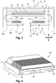
- the picture 3 schematically represents the principle of circulation of a fluid to be cooled, in particular oil, in the heat exchanger 12 as shown in figure 2 .
- the heat exchanger 12 comprises an annular part 18 comprising a first circuit 20 formed by first ducts 22 and second ducts 24 for the circulation of oil to be cooled and a second circuit 26 formed by a first duct 28 and a second conduit 30 for the circulation of defrosting oil from the first 22 and second 24 conduits of the first circuit 20.
- the exchanger 12 is an annular exchanger which extends around the axis 14 of the turbomachine.
- On the picture 3 are represented the longitudinal dimension of the exchanger 12 along the direction L and the circumferential dimension of the exchanger 12 along the direction C.
- the first conduits 22 of the first circuit 20 comprise first portions 22a which extend between a fluid inlet 32 and a first fluid connection member 34a and second portions 22b which extend between a second member 34b fluid connection and an outlet 36 of fluid.
- the second conduits 24 of the first circuit 20 extend between the first fluidic connection member 34a and the second fluidic connection member 34b.
- the oil flows from the fluid inlet 32, in the first portions 22a of the first ducts 22, in the first fluidic connection member 34a, in the second ducts 24 of the first circuit 20, in the second fluidic connection member 34b, in the second portions 22b of the first ducts 22 then towards the outlet 36 of oil.
- the first conduit 28 of the second circuit 26 comprises a first portion 28a which extends between the fluid inlet 32 and the first fluidic connection member 34a and a second portion 28b which extends between the second fluidic connection member 34b and the fluid outlet 36.
- the second conduit 30 of the second circuit 26 extends between the first fluidic connection member 34a and the second fluidic connection member 34b. In this way, the oil flows from the fluid inlet 32, in the first portion 28a of the first conduit 28, in the first fluidic connection member 34a, in the second conduit 30, in the second connecting member 34b fluidic, in the second portion 28b of the first conduit 28 of the second circuit 26 then towards the oil outlet 36.
- the oil of the second circuit 26 can allow defrosting of the first circuit 20 when necessary.
- the connecting members 34a, 34b thus used to achieve the fluidic connection between the first ducts 22, 28 and the second ducts 24, 30 of the first circuit 20 and of the second circuit 26.
- these parts are complicated to realize since they must include oil recirculation channels.
- the purpose of the proposed invention is in particular to provide a simple and effective solution to the aforementioned problems of the prior art.
- a heat exchanger for a turbomachine according to the prior art is known from the document EN 3 060 057 A1 .
- the fluid connection at one end of the exchanger is made directly inside the annular part since the first circuit and the second circuit are formed therein. Unlike the prior art, it is not necessary to require welded or brazed connection parts. Furthermore, the conformation of the first sealing member so as to allow fluid continuity within the first circuit and the second circuit makes it possible to simplify the assembly operation, a single member being necessary at this location. This assembly is also very compact.
- the first sealing member comprises external grooves in which seals are engaged.
- first sealing member may comprise a wall extending in said direction perpendicular to the longitudinal direction and delimiting with the annular part two second substantially parallel connecting channels.
- one of the two second channels can be arranged radially outside the other of the two second channels and the two second channels are fluidically separated from each other by a wall of the first sealing member .
- the first member can be locked in position in the cavity by a plate applied at the level of the circumferential end of said annular part.
- This plate can be secured to the annular part, by screwing for example.
- first and second ducts of the second circuit can be closed off by second members at their ends emerging circumferentially at the level of the first end of the annular part. These second members can be held in position by the aforementioned plate.
- the exchanger 12a also comprises a first oil fluid circuit 37 comprising a plurality of first conduits 38 and second conduits 40 substantially parallel to each other, the first conduits 38 comprising first portions 38a and second portions .
- the exchanger 12a also comprises a second fluid circuit 42 for defrosting comprising a first conduit 44 and a second conduit 46 which are parallel, the first conduit 44 comprising a first portion 44a and a second portion.
- the first ducts 38, 44 and second 40, 42 ducts of the first 37 and second 42 circuits are completely similar to what has been described previously with reference to the picture 3 and differ therefrom only in their fluid connection to each other at the circumferential ends of the heat exchanger. Also, what will be described with reference to the first circumferential end 13 of the heat exchanger 12a is also valid for the opposite second circumferential end. Thus, the description will only be made and represented in relation to the first circumferential end 13 of the exchanger 12a using the second portion of the first pipe 38 of the first circuit 37 and the second pipe 40 of the first circuit 37 as well as using the second portion of the first pipe 38 and the second pipe 46 of the second circuit 42.
- the invention therefore proposes to provide a fluidic connection of the first ducts 38 and second ducts 40 of the first circuit 37 as well as the fluidic connection of the first duct 44 and the second duct 46 of the second circuit 42 without having to use a structurally independent connecting member. of the annular part 48 of the heat exchanger.
- the first step is to obtain a preform of the annular part 48 of the exchanger 12a which is made of a good heat-conducting material such as an alloy of aluminum for example.
- a die is used allowing the simultaneous obtaining of the first ducts 38 and second ducts 40 of the first circuit 37 and of the first duct 44 and of the second duct 46 of the second circuit 42.
- the first ducts 38, 44 and second ducts 40, 46 of the first 37 and second 42 circuits extend from the first end 13 to the second end of the annular part 48 and emerge in the circumferential direction at said ends.
- a cavity is formed in the radial thickness of the annular part 48, the cavity being delimited by dotted lines on the figure 8 and referenced 50.
- the second portions 38a of the first ducts 38 and the second ducts 40 of the first circuit 37 open into this cavity.
- the first portion 44a of the first duct 44 of the second circuit 42 and the second duct 46 of the second circuit 42 emerging only circumferentially at the level of the circumferential end face of the annular part 48, lateral bores 54 are made making it possible to communicating the first portion 44a of the first conduit 44 of the second circuit 42 as well as the second conduit 46 of the second circuit 42 with the aforementioned cavity 50.
- this one has an elongated shape in the longitudinal direction.
- it comprises a first part 52a and a second part 52b substantially identical to each other and symmetrical to each other with respect to the median plane which is in position in the turbomachine a radial plane.
- the first part 52a and the second part 52b are connected to each other by a substantially flat junction wall 52c which extends in a direction perpendicular to the longitudinal direction.
- the first part 52a and the second part 52b each comprise an annular groove 62 in which is mounted an annular sealing gasket 64 ( figure 5A and 7 ).
- the first sealing member 52 is sealingly mounted in the cavity 50 of the annular part, with the annular seals 64 mounted in the grooves 62.
- the end face of the first part 52a of the first member 52 coming opposite -vis and at a distance from the outlets of the first portions 38a of the first ducts 38 and the outlets of the second ducts 40 forms a flow face for the oil in the first channel 55 of connection.
- the first sealing member 52 is dimensioned and the holes 54 are positioned on the annular part 48 so that the hole 54 of the second portion 44a of the first conduit 44 and the hole 54 of the second conduit 46 opens into the second channel 56, 58 of connection.
- each bore 54 is fluidly connected to two second connecting channels 56, 58 substantially parallel to each other, the connecting wall 52c of the first sealing member 52 radially separating the two second channels 56 , 58 binding. It is also observed that the seals 64 seal fluidically between the first circuit 37 and the second circuit 42.
- Second sealing members 66 are inserted, at the level of the first end 13, in the outlet of the second portion 44a of the first conduit 44 of the second circuit 42 and in the outlet of the second conduit 46 of the second circuit 42.
- Each of the second organs 66 comprises an annular groove 68 in which is mounted a seal 68 similar to what has been described with reference to the first member 52, the function being identical.
- a plate 70 is applied to said members at the level of the circumferential end face. This plate is screwed by screws 72 in the annular part.
Landscapes
- Engineering & Computer Science (AREA)
- Mechanical Engineering (AREA)
- General Engineering & Computer Science (AREA)
- Chemical & Material Sciences (AREA)
- Combustion & Propulsion (AREA)
- Physics & Mathematics (AREA)
- Thermal Sciences (AREA)
- Heat-Exchange Devices With Radiators And Conduit Assemblies (AREA)
- Details Of Heat-Exchange And Heat-Transfer (AREA)
- Turbine Rotor Nozzle Sealing (AREA)
Description
- La présente invention concerne un échangeur thermique et plus particulièrement le refroidissement de l'huile dans un moteur d'avion.
- La
figure 1 représente une turbomachine 10 à double flux qui comprend des pièces mobiles qui frottent contre d'autres pièces mobiles ou contre des pièces fixes, cette liaison est par exemple un palier. Pour ne pas se rompre à cause de réchauffement dû aux frottements, les pièces sont arrosées d'huile qui permet d'une part de limiter (ou contenir) leur échauffement et, d'autre part, de les lubrifier pour faciliter le glissement des pièces les unes sur les autres. - L'huile circule dans un circuit pourvu d'échangeurs thermiques, notamment des échangeurs huile/air 12, comme représenté en
figure 2 , ayant une matrice, sous la forme d'une conduite sinueuse conformée de manière à réaliser un échange de chaleur, dans laquelle l'huile provenant desdites pièces est introduite puis refroidie avant d'être de nouveau injectée sur lesdites pièces. L'échangeur thermique 12 représenté enfigure 2 est un échangeur thermique 12 annulaire qui est monté sur la face radialement interne ou externe (par rapport à l'axe longitudinal 14 de la turbomachine) d'une virole annulaire 16 délimitant radialement vers l'extérieur ou l'intérieur une veine annulaire d'écoulement d'un flux d'air secondaire. - La
figure 3 représente de manière schématique le principe de circulation d'un fluide à refroidir, en particulier de l'huile, dans l'échangeur de chaleur 12 comme représenté enfigure 2 . L'échangeur de chaleur 12 comprend une partie annulaire 18 comportant un premier circuit 20 formé de premier conduits 22 et de seconds conduits 24 pour la circulation d'huile à refroidir et un second circuit 26 formé d'un premier conduit 28 et d'un second conduit 30 pour la circulation d'huile de décongélation des premiers 22 et seconds 24 conduits du premier circuit 20. L'échangeur 12 est un échangeur annulaire qui s'étend autour de l'axe 14 de la turbomachine. Sur lafigure 3 sont représentées la dimension longitudinale de l'échangeur 12 selon la direction L et la dimension circonférentielle de l'échangeur 12 selon la direction C. - Comme cela est visible, les premiers conduits 22 du premier circuit 20 comprennent des premières portions 22a qui s'étendent entre une entrée 32 de fluide et un premier organe 34a de liaison fluidique et des secondes portions 22b qui s'étendent entre un second organe 34b de liaison fluidique et une sortie 36 de fluide. Les seconds conduits 24 du premier circuit 20 s'étendent entre le premier organe 34a de liaison fluidique et le second organe 34b de liaison fluidique. De cette manière, l'huile s'écoule depuis l'entrée 32 de fluide, dans les premières portions 22a des premiers conduits 22, dans le premier organe 34a de liaison fluidique, dans les seconds conduits 24 du premier circuit 20, dans le second organe 34b de liaison fluidique, dans les secondes portions 22b des premiers conduits 22 puis vers la sortie 36 d'huile.
- Le premier conduit 28 du second circuit 26 comprend une première portion 28a qui s'étend entre l'entrée 32 de fluide et le premier organe 34a de liaison fluidique et une seconde portion 28b qui s'étend entre le second organe 34b de liaison fluidique et la sortie 36 de fluide.
- Le second conduit 30 du second circuit 26 s'étend entre le premier organe 34a de liaison fluidique et le second organe 34b de liaison fluidique. De cette manière, l'huile s'écoulent depuis l'entrée 32 de fluide, dans la première portion 28a du premier conduit 28, dans le premier organe 34a de liaison fluidique, dans le second conduit 30, dans le second organe 34b de liaison fluidique, dans la seconde portion 28b du premier conduit 28 du second circuit 26 puis vers la sortie d'huile 36. Ainsi conformé, l'huile du second circuit 26 peut permettre une décongélation du premier circuit 20 lorsque cela s'avère nécessaire.
- Comme cela est visible, les organes 34a, 34b de liaison ainsi utilisés pour réaliser la liaison fluidique entre les premiers conduits 22, 28 et les seconds conduits 24, 30 du premier circuit 20 et du second circuit 26. Toutefois, ces pièces sont compliquées à réaliser puisqu'elles doivent comprendre des canaux de recirculation d'huile. De plus, du fait de l'indépendance structurelle de ces organes 34a, 34b de liaison, il est nécessaire de les fixer par soudure ou brasure à la partie annulaire, ce qui impose une vigilance particulière puisqu'il est impératif qu'aucune soudure ou brasure ne vienne obturer, même partiellement, l'écoulement d'huile dans le premier circuit 20 ou le second circuit 26. Il est dès lors nécessaire de mettre en place des opérations de contrôle qualité qui sont longues et couteuses. Par ailleurs, la fixation de ces organes 34a, 34b de liaison les rend non démontables, ce qui n'est pas pratique lorsque l'on souhaite pouvoir inspecter simplement le premier circuit 20 et le second circuit 26. Enfin, étant donné l'emplacement de l'échangeur thermique 12 de la veine annulaire d'écoulement d'air, il est essentiel que sa dimension radiale soit limitée afin de ne pas avoir à modifier le diamètre de la virole, ce qui impacterait nécessairement les autres pièces qui y sont fixées.
- L'invention proposée a notamment pour but d'apporter une solution simple et efficace aux problèmes précités de la technique antérieure.
- Un échangeur thermique pour turbomachine selon l'art antérieur est connu du document
FR 3 060 057 A1 - Il est tout d'abord proposé un échangeur thermique annulaire d'axe longitudinal pour turbomachine, destiné par exemple à être supporté par une virole annulaire d'un carter de la turbomachine, comprenant une partie annulaire monobloc comprenant un premier circuit fluidique comportant au moins un premier conduit et au moins un second conduit s'étendant annulairement et un second circuit fluidique comportant au moins un premier conduit et au moins un second conduit s'étendant annulairement et agencés dans une direction perpendiculaire à la direction longitudinale de part et d'autre des premiers conduit et second conduits du premier circuit, caractérisé en ce que les premier et second conduits du premier circuit ainsi que les premier et second conduits du second circuit débouchent à une première extrémité de ladite partie annulaire dans une cavité débouchant elle-même en direction circonférentielle et dans laquelle est inséré un premier organe d'étanchéité conformé de manière à :
- délimiter avec la partie annulaire au moins un premier canal de liaison fluidique du premier conduit du premier circuit avec le second conduit du premier circuit, et
- délimiter avec la partie annulaire au moins un second canal de liaison fluidique du premier conduit du second circuit avec le second conduit du second circuit, le second canal de liaison étant fluidiquement indépendant du premier canal de liaison.
- Selon l'invention, la liaison fluidique au niveau d'une extrémité de l'échangeur est réalisée directement à l'intérieur de la partie annulaire puisque le premier circuit et le second circuit sont formés dans celui-ci. Au contraire de la technique antérieure, il n'est pas nécessaire de requérir à des parties de liaisons soudées ou brasées. Par ailleurs, la conformation du premier organe d'étanchéité de manière à permettre la continuité fluidique au sein du premier circuit et du second circuit permet de simplifier l'opération d'assemblage, un seul organe étant nécessaire à cet endroit. Cet assemblage s'avère également très compacte.
- Selon une autre caractéristique, le premier organe d'étanchéité comprend des gorges externes dans lesquelles sont engagés des joints d'étanchéité.
- Par ailleurs, le premier organe d'étanchéité peut comprendre une paroi s'étendant dans ladite direction perpendiculaire à la direction longitudinale et délimitant avec la partie annulaire deux seconds canaux de liaisons sensiblement parallèles.
- En outre, l'un des deux seconds canaux peut être agencé radialement à l'extérieur de l'autre des deux seconds canaux et les deux seconds canaux sont séparés fluidiquement l'un de l'autre par une paroi du premier organe d'étanchéité.
- Egalement, le premier organe peut être bloqué en position dans la cavité par une plaque appliquée au niveau de l'extrémité circonférentielle de ladite partie annulaire. Cette plaque peut être rendue solidaire de la partie annulaire, par vissage par exemple.
- Enfin, les premier et second conduits du second circuit peuvent être obturés par des seconds organes à leurs extrémités débouchant circonférentiellement au niveau de la première extrémité de la partie annulaire. Ces seconds organes peuvent être maintenus en position par la plaque précitée.
- L'invention sera mieux comprise et d'autres détails, caractéristiques et avantages de l'invention apparaîtront à la lecture de la description suivante faite à titre d'exemple non limitatif en référence aux dessins annexés.
-
- la
figure 1 est une vue schématique en perspective d'une turbomachine selon la technique connue ; - la
figure 2 est une vue schématique en perspective d'une partie d'un échangeur thermique annulaire montée dans la turbomachine de lafigure 1 ; - la
figure 3 est une illustration schématique de l'échangeur de lafigure 2 et de l'écoulement d'huile à l'intérieur de celui-ci ; - la
figure 4 est une vue schématique en perspective d'une première extrémité d'un échangeur de chaleur selon l'invention : - les
figures 5A et 5B sont des vues schématiques en perspective d'organes d'étanchéité montés sur ladite extrémité de l'échangeur de chaleur ; - la
figure 6 est une vue schématique en perspective de la première extrémité de l'échangeur avec un plaque d'étanchéité montée sur ladite extrémité ; - la
figure 7 est une vue schématique de la première extrémité de l'échangeur de chaleur selon l'invention selon un plan de coupe perpendiculaire à l'axe longitudinal comme illustré par les flèches A en médaillon ; - la
figure 8 est une vue schématique en coupe de ladite première extrémité de l'échangeur thermique, la circulation d'huile étant illustrée. - On se réfère maintenant aux
figures 4 à 8 qui représentent un échangeur de chaleur selon l'invention. De manière similaire à ce qui a été décrit en référence à lafigure 3 , l'échangeur 12a selon l'invention comprend également un premier circuit 37 fluidique d'huile comportant une pluralité de premiers conduits 38 et de seconds 40 conduits sensiblement parallèles les uns aux autres, les premiers conduits 38 comprenant des premières portions 38a et secondes portions. L'échangeur 12a comprend également un second circuit fluidique 42 de décongélation comportant un premier conduit 44 et un second conduit 46 parallèles, le premier conduit 44 comportant une première portion 44a et une seconde portion. - Les premiers conduits 38, 44 et seconds 40, 42 conduits des premier 37 et second 42 circuits sont tout à fait similaires à ce qui a été décrit précédemment en référence à la
figure 3 et diffèrent de ceux-ci uniquement par leur liaison fluidique les uns aux autres au niveau des extrémités circonférentielles de l'échangeur thermique. Egalement, ce qui sera décrit en référence à la première extrémité 13 circonférentielle de l'échangeur thermique 12a est également valable pour la seconde extrémité circonférentielle opposée. Ainsi, la description ne sera effectuée et représentée qu'en relation avec la première extrémité 13 circonférentielle de l'échangeur 12a à l'aide de la seconde portion du premier conduit 38 du premier circuit 37 et du second conduit 40 du premier circuit 37 ainsi qu'à l'aide de la seconde portion du premier conduit 38 et du second conduit 46 du second circuit 42. - L'invention propose donc de réaliser une liaison fluidique des premiers conduits 38 et seconds conduits 40 du premier circuit 37 ainsi que la liaison fluidique du premier conduit 44 et du second conduit 46 du second circuit 42 sans avoir à utiliser un organe de liaison structurellement indépendant de la partie annulaire 48 de l'échangeur de chaleur.
- Afin de réaliser, l'échangeur de chaleur, on procède tout d'abord à l'obtention d'une préforme de la partie annulaire 48 de l'échangeur 12a qui est dans un matériau bon conducteur de la chaleur tel qu'un alliage d'aluminium par exemple. Pour cela, on utilise une filière permettant l'obtention simultanément des premiers conduits 38 et seconds conduits 40 du premier circuit 37 et du premier conduit 44 et du second conduit 46 du second circuit 42. A l'issue de cette étape, les premiers conduits 38, 44 et seconds conduits 40, 46 des premier 37 et second 42 circuits s'étendent de la première extrémité 13 à la seconde extrémité de la partie annulaire 48 et débouchent en direction circonférentielle au niveau desdites extrémités. Dans une étape ultérieure, on forme une cavité dans l'épaisseur radiale de la partie annulaire 48, la cavité étant délimitée en pointillés sur la
figure 8 et référencée 50. Les secondes portions 38a des premiers conduits 38 et les seconds conduits 40 du premier circuit 37 débouchant dans cette cavité. Egalement, la première portion 44a du premier conduit 44 du second circuit 42 et le second conduit 46 du second circuit 42 débouchant uniquement circonférentiellement au niveau de la face d'extrémité circonférentielle de la partie annulaire 48, on réalise des perçages 54 latéraux permettant de faire communiquer la première portion 44a du premier conduit 44 du second circuit 42 ainsi que le second conduit 46 du second circuit 42 avec la cavité 50 précitée. - Afin de permettre une circulation d'huile indépendante entre le premier circuit 37 et le second circuit 42 au niveau de la première extrémité 13, on ajoute un premier organe d'étanchéité 52 qui est conformé de manière particulière, c'est-à-dire de manière :
- à délimiter avec la partie annulaire 48 au moins un premier canal 55 de liaison fluidique du premier conduit 38 du premier circuit 37 avec le second conduit 40 du premier circuit 37 et avec, et
- à délimiter avec la partie annulaire 48 au moins un second canal 56, 58 de liaison fluidique du premier conduit 44 du second circuit 42 avec le second conduit 46 du second circuit 42, le second canal 56, 58 de liaison étant fluidiquement indépendant du premier canal 55 de liaison.
- Afin de comprendre comment le premier organe 52 d'étanchéité délimite pour partie le premier canal 55 de liaison et le second canal 56, 58 de liaison, nous allons maintenant le décrire. Plus particulièrement, celui-ci, représenté en
figure 5A , présente une forme allongée en direction longitudinal. Selon la direction circonférentielle, il comprend une première partie 52a et une seconde partie 52b sensiblement identique l'une à l'autre et symétrique l'une de l'autre par rapport à plan médian qui est en position dans la turbomachine un plan radial. La première partie 52a et la seconde partie 52b sont reliées l'une à l'autre par une paroi 52c de jonction sensiblement plane et qui s'étend dans une direction perpendiculaire à la direction longitudinale. La première partie 52a et la seconde partie 52b comprennent chacune une gorge annulaire 62 dans laquelle est monté un joint 64 annulaire d'étanchéité (figures 5A et7 ). - Le premier organe 52 d'étanchéité est monté à étanchéité dans la cavité 50 de la partie annulaire, avec les joints annulaires 64 montés dans les gorges 62. La face d'extrémité de la première partie 52a du premier organe 52 venant en vis-à-vis et à distance des débouchés des premières portions 38a des premiers conduits 38 et des débouchés des seconds conduits 40 forme une face d'écoulement de l'huile dans le premier canal 55 de liaison. Egalement, le premier organe 52 d'étanchéité est dimensionné et les perçages 54 sont positionnés sur la partie annulaire 48 de manière que le perçage 54 de la seconde portion 44a du premier conduit 44 et le perçage 54 du second conduit 46 débouche dans le second canal 56, 58 de liaison. Plus précisément, on observe que chaque perçage 54 est relié fluidiquement à deux seconds canaux 56, 58 de liaison sensiblement parallèles l'un à l'autre, la paroi 52c de liaison du premier organe 52 d'étanchéité séparant radialement les deux seconds canaux 56, 58 de liaison. On observe également que les joints 64 d'étanchéité assurent l'étanchéité fluidiquement entre le premier circuit 37 et le second circuit 42.
- Des seconds organes 66 d'étanchéité sont insérés, au niveau de la première extrémité 13, dans le débouché de la seconde portion 44a du premier conduit 44 du second circuit 42 et dans le débouché du second conduit 46 du second circuit 42. Chacun des seconds organes 66 comprend une gorge 68 annulaire dans laquelle est monté un joint d'étanchéité 68 de manière similaire à ce qui a été décrit en référence au premier organe 52, la fonction étant identique.
- Afin de maintenir le premier organe 52 d'étanchéité et les seconds organes 66 d'étanchéité en position malgré la pression d'huile, une plaque 70 est appliquée sur lesdits organes au niveau de la face d'extrémité circonférentielle. Cette plaque est vissée par des vis 72 dans la partie annulaire.
Claims (6)
- Echangeur thermique (12a) annulaire d'axe longitudinal (14) pour turbomachine, destiné par exemple à être supporté par une virole
annulaire (16) d'un carter de la turbomachine, comprenant une partie annulaire (48) monobloc comprenant un premier circuit (37) fluidique comportant au moins un premier conduit (38) et au moins un second conduit (40) s'étendant annulairement et un second circuit fluidique (42) comportant au moins un premier conduit (44) et au moins un second conduit (46) s'étendant annulairement et agencés dans une direction perpendiculaire à la direction longitudinale (14) de part et d'autre des premier conduit (38) et second conduit (40) du premier circuit (37), caractérisé en ce que les premier (38) et second (40) conduits du premier circuit (37) ainsi que les premier (44) et second (46) conduits du second circuit (42) débouchent à une première extrémité (13) de ladite partie annulaire (48) dans une cavité (50) débouchant elle-même en direction circonférentielle et dans laquelle est inséré un premier organe (52) d'étanchéité conformé de manière à :- délimiter avec la partie annulaire (48) au moins un premier canal (55) de liaison fluidique du premier conduit (38) du premier circuit (37) avec le second conduit (40) du premier circuit (37), et- délimiter avec la partie annulaire (48) au moins un second canal (56, 58) de liaison fluidique du premier conduit (44) du second circuit (42) avec le second conduit (46) du second circuit (42), le second canal (56, 58) de liaison étant fluidiquement indépendant du premier canal (55) de liaison. - Echangeur thermique selon la revendication 1, dans lequel le premier organe (52) d'étanchéité comprend des gorges (62) externes dans lesquelles sont engagés des joints (64) d'étanchéité.
- Echangeur thermique selon la revendication 1 ou 2, dans lequel le premier organe (52) d'étanchéité comprend une paroi (52c) s'étendant dans ladite direction perpendiculaire à la direction longitudinale et délimitant avec la partie annulaire (48) deux seconds canaux (56, 58) de liaisons sensiblement parallèles.
- Echangeur selon la revendication 3, dans lequel l'un des deux seconds canaux (56, 58) est agencé radialement à l'extérieur de l'autre des deux seconds canaux et les deux seconds canaux sont séparés fluidiquement l'un de l'autre par la
paroi (52c) du premier organe (52) d'étanchéité. - Echangeur selon l'une des revendications précédentes, dans lequel le premier organe (52) est bloqué en position dans la cavité (50) par une plaque (70) appliquée au niveau de l'extrémité circonférentielle de ladite partie annulaire (48).
- Echangeur selon l'une des revendications précédentes, dans lequel les premier et second conduits du second circuit (42) sont obturés par des seconds organes (66) à leurs extrémités débouchant circonférentiellement au niveau de la première extrémité de la partie annulaire (48).
Applications Claiming Priority (2)
| Application Number | Priority Date | Filing Date | Title |
|---|---|---|---|
| FR1857153A FR3084698B1 (fr) | 2018-07-31 | 2018-07-31 | Echangeur thermique pour turbomachine |
| PCT/FR2019/051870 WO2020025894A1 (fr) | 2018-07-31 | 2019-07-30 | Echangeur thermique pour turbomachine |
Publications (2)
| Publication Number | Publication Date |
|---|---|
| EP3830401A1 EP3830401A1 (fr) | 2021-06-09 |
| EP3830401B1 true EP3830401B1 (fr) | 2022-09-07 |
Family
ID=65200964
Family Applications (1)
| Application Number | Title | Priority Date | Filing Date |
|---|---|---|---|
| EP19765528.5A Active EP3830401B1 (fr) | 2018-07-31 | 2019-07-30 | Échangeur thermique pour turbomachine |
Country Status (6)
| Country | Link |
|---|---|
| US (1) | US11428167B2 (fr) |
| EP (1) | EP3830401B1 (fr) |
| JP (1) | JP7448520B2 (fr) |
| CN (1) | CN112601882B (fr) |
| FR (1) | FR3084698B1 (fr) |
| WO (1) | WO2020025894A1 (fr) |
Family Cites Families (23)
| Publication number | Priority date | Publication date | Assignee | Title |
|---|---|---|---|---|
| JPS60182105U (ja) * | 1984-05-14 | 1985-12-03 | 株式会社 太平製作所 | 熱板の媒体通路 |
| JP2007071432A (ja) | 2005-09-06 | 2007-03-22 | Showa Denko Kk | 熱交換器およびその製造方法 |
| US7823374B2 (en) * | 2006-08-31 | 2010-11-02 | General Electric Company | Heat transfer system and method for turbine engine using heat pipes |
| DE112014000721T5 (de) * | 2013-02-08 | 2015-10-29 | Dana Canada Corporation | Wärmetauscher mit ringförmigem Einlass/Auslass-Anschlussstück |
| FR3009862B1 (fr) * | 2013-08-26 | 2015-09-11 | Commissariat Energie Atomique | Echangeur de chaleur entre deux fluides, utilisation de l'echangeur avec du metal liquide et du gaz, application a un reacteur nucleaire a neutrons rapides refroidi avec du metal liquide |
| FR3012212B1 (fr) * | 2013-10-18 | 2018-01-12 | Safran Aircraft Engines | Echangeur de chaleur pour turbomachine |
| US9677474B2 (en) * | 2013-11-18 | 2017-06-13 | Unison Industries, Llc | Surface cooler support mechanism |
| FR3015654B1 (fr) * | 2013-12-23 | 2015-12-04 | Snecma | Echangeur de chaleur d'une turbomachine |
| JP2015175562A (ja) * | 2014-03-17 | 2015-10-05 | カルソニックカンセイ株式会社 | 熱交換器 |
| US20170211478A1 (en) * | 2014-04-11 | 2017-07-27 | Unison Industries, Llc | Tubular cooler with integrated fan |
| US9777963B2 (en) * | 2014-06-30 | 2017-10-03 | General Electric Company | Method and system for radial tubular heat exchangers |
| JP2016145524A (ja) | 2015-02-06 | 2016-08-12 | 株式会社デンソー | Egrクーラ |
| FR3034474B1 (fr) * | 2015-04-01 | 2019-08-09 | Safran Aircraft Engines | Turbomachine equipee d'un secteur d'aubage et d'un circuit de refroidissement |
| US9765660B2 (en) * | 2015-05-29 | 2017-09-19 | Honeywell International Inc. | Internal bypass to improve decongealing of surface type air to oil coolers |
| FR3037387B1 (fr) * | 2015-06-12 | 2019-07-19 | Valeo Systemes Thermiques | Echangeur de chaleur pour vehicule automobile |
| FR3046199B1 (fr) * | 2015-12-23 | 2017-12-29 | Snecma | Turbomachine comprenant un echangeur air-huile surfacique integre a un compartiment inter-veines |
| US10697371B2 (en) * | 2015-12-28 | 2020-06-30 | General Electric Company | Method and system for a combined air-oil cooler and fuel-oil cooler heat exchanger |
| US10126062B2 (en) | 2016-01-08 | 2018-11-13 | General Electric Company | Heat exchanger for embedded engine applications |
| FR3050763B1 (fr) * | 2016-04-28 | 2018-04-13 | Safran Aircraft Engines | Dispositif de circulation d'air pour une turbomachine comportant un systeme de derivation d'air chaud vers un echangeur de chaleur |
| FR3060057B1 (fr) * | 2016-12-14 | 2019-08-30 | Safran Aircraft Engines | Circuit fluidique dans une turbomachine |
| US20180328285A1 (en) * | 2017-05-11 | 2018-11-15 | Unison Industries, Llc | Heat exchanger |
| EP3413001B1 (fr) * | 2017-06-06 | 2020-01-08 | Ge Avio S.r.l. | Échangeur de chaleur fabriqué par production additive |
| US20200200040A1 (en) * | 2018-12-19 | 2020-06-25 | Unison Industries, Llc | Aircraft surface cooler assembly |
-
2018
- 2018-07-31 FR FR1857153A patent/FR3084698B1/fr not_active Expired - Fee Related
-
2019
- 2019-07-30 US US17/264,643 patent/US11428167B2/en active Active
- 2019-07-30 WO PCT/FR2019/051870 patent/WO2020025894A1/fr not_active Ceased
- 2019-07-30 JP JP2021505297A patent/JP7448520B2/ja active Active
- 2019-07-30 CN CN201980055567.XA patent/CN112601882B/zh active Active
- 2019-07-30 EP EP19765528.5A patent/EP3830401B1/fr active Active
Also Published As
| Publication number | Publication date |
|---|---|
| CN112601882B (zh) | 2024-06-07 |
| FR3084698B1 (fr) | 2020-07-24 |
| US20210310410A1 (en) | 2021-10-07 |
| FR3084698A1 (fr) | 2020-02-07 |
| JP7448520B2 (ja) | 2024-03-12 |
| EP3830401A1 (fr) | 2021-06-09 |
| CN112601882A (zh) | 2021-04-02 |
| JP2021533323A (ja) | 2021-12-02 |
| WO2020025894A1 (fr) | 2020-02-06 |
| US11428167B2 (en) | 2022-08-30 |
Similar Documents
| Publication | Publication Date | Title |
|---|---|---|
| EP1482127B1 (fr) | Système d' étanchéité du flux secondaire à l' entrée d'une tuyère d'une turbomachine avec chambre de post-combustion. | |
| CA2998581A1 (fr) | Cylindre detendeur a double effet a support adaptatif | |
| EP0647822B1 (fr) | Echangeur de chaleur à lames utile notamment comme refroidisseur d'huile | |
| EP2199721A1 (fr) | Echangeur thermique interne pour circuit de climatisation de véhicule automobile, un tel circuit et procédé de raccordement d'un connecteur à cet échangeur. | |
| EP3830403B1 (fr) | Échangeur thermique pour turbomachine et procédé de fabrication associé | |
| WO2009062944A1 (fr) | Dispositif de refroidissement d'un fluide caloporteur | |
| EP4083489B1 (fr) | Connecteur | |
| EP3830401B1 (fr) | Échangeur thermique pour turbomachine | |
| EP1985945B1 (fr) | Echangeur thermique interne pour circuit de climatisation de véhicule automobile, un tel circuit et procédé de raccordement de deux connecteurs à cet échangeur | |
| FR3072127B1 (fr) | Conduit de decharge d'un moyeu de carter intermediaire pour turboreacteur d'aeronef comportant des canaux de refroidissement | |
| WO2008009822A2 (fr) | Element thermostatique, vanne de regulation comportant un tel element et circuit de liquide de refroidissement incorporant une telle vanne | |
| FR3068121B1 (fr) | Echangeur de chaleur a reservoir de materiau a changement de phase comprenant une languette de maintien et d'obturation d'un tube de remplissage | |
| EP3807506B1 (fr) | Procede de fabrication d'un echangeur thermique pour une turbomachine | |
| EP3183444A1 (fr) | Carter cylindre d'un moteur thermique | |
| CA2958025C (fr) | Dispositif de raccordement comportant plusieurs tubes concentriques cintres | |
| FR2908155A1 (fr) | Vanne thermostatique multivoies pour la distribution selective et la regulation de debit d'un liquide de refroidissement dans un circuit de refroidissement d'un moteur de vehicule automobile | |
| FR2707380A1 (fr) | Echangeur annulaire de sécurité pour fluides incompatibles. | |
| FR3108934A1 (fr) | Dispositif de drainage pour une turbomachine d’aeronef | |
| EP2912397A1 (fr) | Boite collectrice pour échangeur de chaleur, notamment refroidisseur d'air de suralimentation de moteur de véhicule automobile | |
| WO2026052908A1 (fr) | Turbomachine d'aéronef comprenant un échangeur de chaleur amélioré | |
| FR3161583A1 (fr) | Module à braser sur une conduite de circuit de fluide réfrigérant | |
| EP1743094A1 (fr) | Conduit de refroidissement moteur |
Legal Events
| Date | Code | Title | Description |
|---|---|---|---|
| STAA | Information on the status of an ep patent application or granted ep patent |
Free format text: STATUS: UNKNOWN |
|
| STAA | Information on the status of an ep patent application or granted ep patent |
Free format text: STATUS: THE INTERNATIONAL PUBLICATION HAS BEEN MADE |
|
| PUAI | Public reference made under article 153(3) epc to a published international application that has entered the european phase |
Free format text: ORIGINAL CODE: 0009012 |
|
| STAA | Information on the status of an ep patent application or granted ep patent |
Free format text: STATUS: REQUEST FOR EXAMINATION WAS MADE |
|
| 17P | Request for examination filed |
Effective date: 20210224 |
|
| AK | Designated contracting states |
Kind code of ref document: A1 Designated state(s): AL AT BE BG CH CY CZ DE DK EE ES FI FR GB GR HR HU IE IS IT LI LT LU LV MC MK MT NL NO PL PT RO RS SE SI SK SM TR |
|
| DAV | Request for validation of the european patent (deleted) | ||
| DAX | Request for extension of the european patent (deleted) | ||
| GRAP | Despatch of communication of intention to grant a patent |
Free format text: ORIGINAL CODE: EPIDOSNIGR1 |
|
| STAA | Information on the status of an ep patent application or granted ep patent |
Free format text: STATUS: GRANT OF PATENT IS INTENDED |
|
| INTG | Intention to grant announced |
Effective date: 20220329 |
|
| GRAS | Grant fee paid |
Free format text: ORIGINAL CODE: EPIDOSNIGR3 |
|
| GRAA | (expected) grant |
Free format text: ORIGINAL CODE: 0009210 |
|
| STAA | Information on the status of an ep patent application or granted ep patent |
Free format text: STATUS: THE PATENT HAS BEEN GRANTED |
|
| AK | Designated contracting states |
Kind code of ref document: B1 Designated state(s): AL AT BE BG CH CY CZ DE DK EE ES FI FR GB GR HR HU IE IS IT LI LT LU LV MC MK MT NL NO PL PT RO RS SE SI SK SM TR |
|
| REG | Reference to a national code |
Ref country code: GB Ref legal event code: FG4D Free format text: NOT ENGLISH |
|
| REG | Reference to a national code |
Ref country code: CH Ref legal event code: EP Ref country code: AT Ref legal event code: REF Ref document number: 1517216 Country of ref document: AT Kind code of ref document: T Effective date: 20220915 |
|
| REG | Reference to a national code |
Ref country code: IE Ref legal event code: FG4D Free format text: LANGUAGE OF EP DOCUMENT: FRENCH |
|
| REG | Reference to a national code |
Ref country code: DE Ref legal event code: R096 Ref document number: 602019019361 Country of ref document: DE |
|
| REG | Reference to a national code |
Ref country code: LT Ref legal event code: MG9D |
|
| REG | Reference to a national code |
Ref country code: NL Ref legal event code: MP Effective date: 20220907 |
|
| PG25 | Lapsed in a contracting state [announced via postgrant information from national office to epo] |
Ref country code: SE Free format text: LAPSE BECAUSE OF FAILURE TO SUBMIT A TRANSLATION OF THE DESCRIPTION OR TO PAY THE FEE WITHIN THE PRESCRIBED TIME-LIMIT Effective date: 20220907 Ref country code: RS Free format text: LAPSE BECAUSE OF FAILURE TO SUBMIT A TRANSLATION OF THE DESCRIPTION OR TO PAY THE FEE WITHIN THE PRESCRIBED TIME-LIMIT Effective date: 20220907 Ref country code: NO Free format text: LAPSE BECAUSE OF FAILURE TO SUBMIT A TRANSLATION OF THE DESCRIPTION OR TO PAY THE FEE WITHIN THE PRESCRIBED TIME-LIMIT Effective date: 20221207 Ref country code: LV Free format text: LAPSE BECAUSE OF FAILURE TO SUBMIT A TRANSLATION OF THE DESCRIPTION OR TO PAY THE FEE WITHIN THE PRESCRIBED TIME-LIMIT Effective date: 20220907 Ref country code: LT Free format text: LAPSE BECAUSE OF FAILURE TO SUBMIT A TRANSLATION OF THE DESCRIPTION OR TO PAY THE FEE WITHIN THE PRESCRIBED TIME-LIMIT Effective date: 20220907 Ref country code: FI Free format text: LAPSE BECAUSE OF FAILURE TO SUBMIT A TRANSLATION OF THE DESCRIPTION OR TO PAY THE FEE WITHIN THE PRESCRIBED TIME-LIMIT Effective date: 20220907 |
|
| REG | Reference to a national code |
Ref country code: AT Ref legal event code: MK05 Ref document number: 1517216 Country of ref document: AT Kind code of ref document: T Effective date: 20220907 |
|
| PG25 | Lapsed in a contracting state [announced via postgrant information from national office to epo] |
Ref country code: HR Free format text: LAPSE BECAUSE OF FAILURE TO SUBMIT A TRANSLATION OF THE DESCRIPTION OR TO PAY THE FEE WITHIN THE PRESCRIBED TIME-LIMIT Effective date: 20220907 Ref country code: GR Free format text: LAPSE BECAUSE OF FAILURE TO SUBMIT A TRANSLATION OF THE DESCRIPTION OR TO PAY THE FEE WITHIN THE PRESCRIBED TIME-LIMIT Effective date: 20221208 |
|
| PG25 | Lapsed in a contracting state [announced via postgrant information from national office to epo] |
Ref country code: SM Free format text: LAPSE BECAUSE OF FAILURE TO SUBMIT A TRANSLATION OF THE DESCRIPTION OR TO PAY THE FEE WITHIN THE PRESCRIBED TIME-LIMIT Effective date: 20220907 Ref country code: RO Free format text: LAPSE BECAUSE OF FAILURE TO SUBMIT A TRANSLATION OF THE DESCRIPTION OR TO PAY THE FEE WITHIN THE PRESCRIBED TIME-LIMIT Effective date: 20220907 Ref country code: PT Free format text: LAPSE BECAUSE OF FAILURE TO SUBMIT A TRANSLATION OF THE DESCRIPTION OR TO PAY THE FEE WITHIN THE PRESCRIBED TIME-LIMIT Effective date: 20230109 Ref country code: ES Free format text: LAPSE BECAUSE OF FAILURE TO SUBMIT A TRANSLATION OF THE DESCRIPTION OR TO PAY THE FEE WITHIN THE PRESCRIBED TIME-LIMIT Effective date: 20220907 Ref country code: CZ Free format text: LAPSE BECAUSE OF FAILURE TO SUBMIT A TRANSLATION OF THE DESCRIPTION OR TO PAY THE FEE WITHIN THE PRESCRIBED TIME-LIMIT Effective date: 20220907 Ref country code: AT Free format text: LAPSE BECAUSE OF FAILURE TO SUBMIT A TRANSLATION OF THE DESCRIPTION OR TO PAY THE FEE WITHIN THE PRESCRIBED TIME-LIMIT Effective date: 20220907 |
|
| PG25 | Lapsed in a contracting state [announced via postgrant information from national office to epo] |
Ref country code: SK Free format text: LAPSE BECAUSE OF FAILURE TO SUBMIT A TRANSLATION OF THE DESCRIPTION OR TO PAY THE FEE WITHIN THE PRESCRIBED TIME-LIMIT Effective date: 20220907 Ref country code: PL Free format text: LAPSE BECAUSE OF FAILURE TO SUBMIT A TRANSLATION OF THE DESCRIPTION OR TO PAY THE FEE WITHIN THE PRESCRIBED TIME-LIMIT Effective date: 20220907 Ref country code: IS Free format text: LAPSE BECAUSE OF FAILURE TO SUBMIT A TRANSLATION OF THE DESCRIPTION OR TO PAY THE FEE WITHIN THE PRESCRIBED TIME-LIMIT Effective date: 20230107 Ref country code: EE Free format text: LAPSE BECAUSE OF FAILURE TO SUBMIT A TRANSLATION OF THE DESCRIPTION OR TO PAY THE FEE WITHIN THE PRESCRIBED TIME-LIMIT Effective date: 20220907 |
|
| REG | Reference to a national code |
Ref country code: DE Ref legal event code: R097 Ref document number: 602019019361 Country of ref document: DE |
|
| PG25 | Lapsed in a contracting state [announced via postgrant information from national office to epo] |
Ref country code: NL Free format text: LAPSE BECAUSE OF FAILURE TO SUBMIT A TRANSLATION OF THE DESCRIPTION OR TO PAY THE FEE WITHIN THE PRESCRIBED TIME-LIMIT Effective date: 20220907 Ref country code: AL Free format text: LAPSE BECAUSE OF FAILURE TO SUBMIT A TRANSLATION OF THE DESCRIPTION OR TO PAY THE FEE WITHIN THE PRESCRIBED TIME-LIMIT Effective date: 20220907 |
|
| PLBE | No opposition filed within time limit |
Free format text: ORIGINAL CODE: 0009261 |
|
| STAA | Information on the status of an ep patent application or granted ep patent |
Free format text: STATUS: NO OPPOSITION FILED WITHIN TIME LIMIT |
|
| PG25 | Lapsed in a contracting state [announced via postgrant information from national office to epo] |
Ref country code: DK Free format text: LAPSE BECAUSE OF FAILURE TO SUBMIT A TRANSLATION OF THE DESCRIPTION OR TO PAY THE FEE WITHIN THE PRESCRIBED TIME-LIMIT Effective date: 20220907 |
|
| 26N | No opposition filed |
Effective date: 20230608 |
|
| PG25 | Lapsed in a contracting state [announced via postgrant information from national office to epo] |
Ref country code: SI Free format text: LAPSE BECAUSE OF FAILURE TO SUBMIT A TRANSLATION OF THE DESCRIPTION OR TO PAY THE FEE WITHIN THE PRESCRIBED TIME-LIMIT Effective date: 20220907 |
|
| PG25 | Lapsed in a contracting state [announced via postgrant information from national office to epo] |
Ref country code: MC Free format text: LAPSE BECAUSE OF FAILURE TO SUBMIT A TRANSLATION OF THE DESCRIPTION OR TO PAY THE FEE WITHIN THE PRESCRIBED TIME-LIMIT Effective date: 20220907 |
|
| PG25 | Lapsed in a contracting state [announced via postgrant information from national office to epo] |
Ref country code: MC Free format text: LAPSE BECAUSE OF FAILURE TO SUBMIT A TRANSLATION OF THE DESCRIPTION OR TO PAY THE FEE WITHIN THE PRESCRIBED TIME-LIMIT Effective date: 20220907 |
|
| REG | Reference to a national code |
Ref country code: CH Ref legal event code: PL |
|
| REG | Reference to a national code |
Ref country code: BE Ref legal event code: MM Effective date: 20230731 |
|
| PG25 | Lapsed in a contracting state [announced via postgrant information from national office to epo] |
Ref country code: LU Free format text: LAPSE BECAUSE OF NON-PAYMENT OF DUE FEES Effective date: 20230730 |
|
| PG25 | Lapsed in a contracting state [announced via postgrant information from national office to epo] |
Ref country code: LU Free format text: LAPSE BECAUSE OF NON-PAYMENT OF DUE FEES Effective date: 20230730 |
|
| REG | Reference to a national code |
Ref country code: IE Ref legal event code: MM4A |
|
| PG25 | Lapsed in a contracting state [announced via postgrant information from national office to epo] |
Ref country code: CH Free format text: LAPSE BECAUSE OF NON-PAYMENT OF DUE FEES Effective date: 20230731 |
|
| PG25 | Lapsed in a contracting state [announced via postgrant information from national office to epo] |
Ref country code: IT Free format text: LAPSE BECAUSE OF FAILURE TO SUBMIT A TRANSLATION OF THE DESCRIPTION OR TO PAY THE FEE WITHIN THE PRESCRIBED TIME-LIMIT Effective date: 20220907 Ref country code: BE Free format text: LAPSE BECAUSE OF NON-PAYMENT OF DUE FEES Effective date: 20230731 |
|
| PG25 | Lapsed in a contracting state [announced via postgrant information from national office to epo] |
Ref country code: IE Free format text: LAPSE BECAUSE OF NON-PAYMENT OF DUE FEES Effective date: 20230730 |
|
| PG25 | Lapsed in a contracting state [announced via postgrant information from national office to epo] |
Ref country code: IE Free format text: LAPSE BECAUSE OF NON-PAYMENT OF DUE FEES Effective date: 20230730 |
|
| PG25 | Lapsed in a contracting state [announced via postgrant information from national office to epo] |
Ref country code: BG Free format text: LAPSE BECAUSE OF FAILURE TO SUBMIT A TRANSLATION OF THE DESCRIPTION OR TO PAY THE FEE WITHIN THE PRESCRIBED TIME-LIMIT Effective date: 20220907 |
|
| PG25 | Lapsed in a contracting state [announced via postgrant information from national office to epo] |
Ref country code: BG Free format text: LAPSE BECAUSE OF FAILURE TO SUBMIT A TRANSLATION OF THE DESCRIPTION OR TO PAY THE FEE WITHIN THE PRESCRIBED TIME-LIMIT Effective date: 20220907 |
|
| PG25 | Lapsed in a contracting state [announced via postgrant information from national office to epo] |
Ref country code: CY Free format text: LAPSE BECAUSE OF FAILURE TO SUBMIT A TRANSLATION OF THE DESCRIPTION OR TO PAY THE FEE WITHIN THE PRESCRIBED TIME-LIMIT; INVALID AB INITIO Effective date: 20190730 |
|
| PG25 | Lapsed in a contracting state [announced via postgrant information from national office to epo] |
Ref country code: HU Free format text: LAPSE BECAUSE OF FAILURE TO SUBMIT A TRANSLATION OF THE DESCRIPTION OR TO PAY THE FEE WITHIN THE PRESCRIBED TIME-LIMIT; INVALID AB INITIO Effective date: 20190730 |
|
| PGFP | Annual fee paid to national office [announced via postgrant information from national office to epo] |
Ref country code: DE Payment date: 20250722 Year of fee payment: 7 |
|
| PGFP | Annual fee paid to national office [announced via postgrant information from national office to epo] |
Ref country code: GB Payment date: 20250724 Year of fee payment: 7 |
|
| PGFP | Annual fee paid to national office [announced via postgrant information from national office to epo] |
Ref country code: FR Payment date: 20250722 Year of fee payment: 7 |
|
| PG25 | Lapsed in a contracting state [announced via postgrant information from national office to epo] |
Ref country code: TR Free format text: LAPSE BECAUSE OF FAILURE TO SUBMIT A TRANSLATION OF THE DESCRIPTION OR TO PAY THE FEE WITHIN THE PRESCRIBED TIME-LIMIT Effective date: 20220907 |