EP3829476B1 - Verfahren und system zum aktualisieren eines betriebswegs für eine roboterarmbaugruppe. - Google Patents
Verfahren und system zum aktualisieren eines betriebswegs für eine roboterarmbaugruppe. Download PDFInfo
- Publication number
- EP3829476B1 EP3829476B1 EP19844408.5A EP19844408A EP3829476B1 EP 3829476 B1 EP3829476 B1 EP 3829476B1 EP 19844408 A EP19844408 A EP 19844408A EP 3829476 B1 EP3829476 B1 EP 3829476B1
- Authority
- EP
- European Patent Office
- Prior art keywords
- point
- image
- distance
- coordinate system
- tag
- Prior art date
- Legal status (The legal status is an assumption and is not a legal conclusion. Google has not performed a legal analysis and makes no representation as to the accuracy of the status listed.)
- Active
Links
Images


Classifications
-
- A—HUMAN NECESSITIES
- A61—MEDICAL OR VETERINARY SCIENCE; HYGIENE
- A61B—DIAGNOSIS; SURGERY; IDENTIFICATION
- A61B34/00—Computer-aided surgery; Manipulators or robots specially adapted for use in surgery
- A61B34/20—Surgical navigation systems; Devices for tracking or guiding surgical instruments, e.g. for frameless stereotaxis
-
- A—HUMAN NECESSITIES
- A61—MEDICAL OR VETERINARY SCIENCE; HYGIENE
- A61B—DIAGNOSIS; SURGERY; IDENTIFICATION
- A61B34/00—Computer-aided surgery; Manipulators or robots specially adapted for use in surgery
- A61B34/10—Computer-aided planning, simulation or modelling of surgical operations
-
- A—HUMAN NECESSITIES
- A61—MEDICAL OR VETERINARY SCIENCE; HYGIENE
- A61B—DIAGNOSIS; SURGERY; IDENTIFICATION
- A61B34/00—Computer-aided surgery; Manipulators or robots specially adapted for use in surgery
- A61B34/30—Surgical robots
-
- A—HUMAN NECESSITIES
- A61—MEDICAL OR VETERINARY SCIENCE; HYGIENE
- A61B—DIAGNOSIS; SURGERY; IDENTIFICATION
- A61B90/00—Instruments, implements or accessories specially adapted for surgery or diagnosis and not covered by any of the groups A61B1/00 - A61B50/00, e.g. for luxation treatment or for protecting wound edges
- A61B90/36—Image-producing devices or illumination devices not otherwise provided for
- A61B90/361—Image-producing devices, e.g. surgical cameras
-
- A—HUMAN NECESSITIES
- A61—MEDICAL OR VETERINARY SCIENCE; HYGIENE
- A61B—DIAGNOSIS; SURGERY; IDENTIFICATION
- A61B90/00—Instruments, implements or accessories specially adapted for surgery or diagnosis and not covered by any of the groups A61B1/00 - A61B50/00, e.g. for luxation treatment or for protecting wound edges
- A61B90/39—Markers, e.g. radio-opaque or breast lesions markers
-
- A—HUMAN NECESSITIES
- A61—MEDICAL OR VETERINARY SCIENCE; HYGIENE
- A61B—DIAGNOSIS; SURGERY; IDENTIFICATION
- A61B17/00—Surgical instruments, devices or methods
- A61B2017/00681—Aspects not otherwise provided for
- A61B2017/00694—Aspects not otherwise provided for with means correcting for movement of or for synchronisation with the body
-
- A—HUMAN NECESSITIES
- A61—MEDICAL OR VETERINARY SCIENCE; HYGIENE
- A61B—DIAGNOSIS; SURGERY; IDENTIFICATION
- A61B34/00—Computer-aided surgery; Manipulators or robots specially adapted for use in surgery
- A61B34/10—Computer-aided planning, simulation or modelling of surgical operations
- A61B2034/107—Visualisation of planned trajectories or target regions
-
- A—HUMAN NECESSITIES
- A61—MEDICAL OR VETERINARY SCIENCE; HYGIENE
- A61B—DIAGNOSIS; SURGERY; IDENTIFICATION
- A61B34/00—Computer-aided surgery; Manipulators or robots specially adapted for use in surgery
- A61B34/20—Surgical navigation systems; Devices for tracking or guiding surgical instruments, e.g. for frameless stereotaxis
- A61B2034/2046—Tracking techniques
- A61B2034/2055—Optical tracking systems
-
- A—HUMAN NECESSITIES
- A61—MEDICAL OR VETERINARY SCIENCE; HYGIENE
- A61B—DIAGNOSIS; SURGERY; IDENTIFICATION
- A61B34/00—Computer-aided surgery; Manipulators or robots specially adapted for use in surgery
- A61B34/20—Surgical navigation systems; Devices for tracking or guiding surgical instruments, e.g. for frameless stereotaxis
- A61B2034/2046—Tracking techniques
- A61B2034/2065—Tracking using image or pattern recognition
-
- A—HUMAN NECESSITIES
- A61—MEDICAL OR VETERINARY SCIENCE; HYGIENE
- A61B—DIAGNOSIS; SURGERY; IDENTIFICATION
- A61B90/00—Instruments, implements or accessories specially adapted for surgery or diagnosis and not covered by any of the groups A61B1/00 - A61B50/00, e.g. for luxation treatment or for protecting wound edges
- A61B90/36—Image-producing devices or illumination devices not otherwise provided for
- A61B2090/364—Correlation of different images or relation of image positions in respect to the body
-
- A—HUMAN NECESSITIES
- A61—MEDICAL OR VETERINARY SCIENCE; HYGIENE
- A61B—DIAGNOSIS; SURGERY; IDENTIFICATION
- A61B90/00—Instruments, implements or accessories specially adapted for surgery or diagnosis and not covered by any of the groups A61B1/00 - A61B50/00, e.g. for luxation treatment or for protecting wound edges
- A61B90/39—Markers, e.g. radio-opaque or breast lesions markers
- A61B2090/3983—Reference marker arrangements for use with image guided surgery
Definitions
- Embodiments of the present invention relate generally to methods and systems of tracking a position or an orientation of a patient in an operation.
- Robotic operation may offer a precise control of the operation pathway.
- patient is subjected to a medical scan (e.g., CT or MRI).
- the operation pathway to the desired anatomical region is planned based on the medical scan.
- Artificial intelligence may be employed to suggest the surgeon with optimal routes that incur the least amount of damages.
- the position of the patient may be matched to the perspective of the medical scan to accurate perform the operation along the planned operation pathway.
- the position of the patient may be moved. Accordingly, the planned operation pathway may not be applicable in view of the moved position of the patient and may be updated in response to the moved position of the patient.
- WO 2018/073452 A1 discloses a recalibration device used during the acquisition of images of an anatomical area of a patient during robotassisted surgery, including a three dimensional body made of radiolucent material, said body having an upper surface and an opposite surface forming a bearing surface to be manually placed on a surface of said anatomical area of the patient, said body comprises fiducial markers made of radiopaque material, wherein said fiducial markers are arranged between the upper surface and the bearing surface in at least one specific geometrical pattern permitting a certain detection of the position and the orientation of the recalibration device in a three-dimensional digital model built from the images resulting from the acquisition of the anatomical area.
- WO 2018/081136 A1 discloses a method for defining a boundary surface for a robotic surgery system, comprising: identifying at least a portion of a skin surface of a patent in an image dataset of the patient' s anatomy; generating a boundary surface based on the identified skin surface; registering the image dataset and the boundary surface within a patient coordinate system; and controlling a robotic arm to prevent at least a portion of the robotic arm from crossing the boundary surface.
- CN104083217A discloses a surgical positioning device that comprises a positioning ruler, a host computer and a series manipulator arm with at least six degrees of freedom.
- the host computer is connected with the series manipulator arm, and the positioning ruler includes two opposite surfaces that are transparent to X-rays.
- the two opposite surfaces are fixedly connected by an X-ray-transparent connecting surface, and a group of marks are provided on the two opposite surfaces, and each group of marks includes at least four mark points that are not on a straight line, and the mark points are opaque to X-rays.
- Any opposite surface or connecting surface is fixedly connected to a ruler handle, and the ruler handle is connected with the end of a serial manipulator through an interface.
- the computer adjusts the position of the positioning ruler by controlling the movement of the serial manipulator for transmission.
- the angle is transformed, and the spatial positioning calculation is performed according to the marked points in the collected images to obtain the planned path.
- US 2018/0092699 A1 discloses a system for surgical navigation, comprising: a first array including tracking markers, the first array releasably secured with a first anatomical feature; and at least one camera configured to track the array and transmit the images of the array to a computer system including a processor, wherein the computer system is configured to display a simulation of the anatomical feature on a display screen.
- Fig. 1 is an example figure showing operation system 100 configured to perform an operation on patient 101, arranged in accordance with some embodiments of the present disclosure.
- operation system 100 includes frame 120, operating table 130 and robotic arm assembly 140.
- frame 120 is configured to support and attach to an operation target (e.g., patient's head 103) of patient 110.
- frame 120 is also configured to attach to operating table 130.
- frame 120 further includes tag 121.
- Tag 121 is fixed or integrally formed with frame 120. Therefore, patient's head 103, operating table 130, frame 120 and tag 121 together may form a predetermined spatial relationship. In other words, in response to a first movement of patient's head 103, tag 121 also has a corresponding second movement based on the predetermined spatial relationship. Accordingly, the movement of tag 121 may also be used to determine whether the patient's head has moved.
- frame 121 may include more than one tags. Each tag may include a unique identification pattern from each other. Accordingly, operating system 100 may process different requirements based on these tags.
- robotic arm assembly 140 may include surgical instrument 141, optical apparatus 143, first arm 147, second arm 148 and third arm 149.
- optical apparatus 143 is an IR camera capable of capturing images of tag 121 at different times. These captured images are processed to identify whether a movement of tag 121 exceeds a threshold.
- a processor (not shown) associated with robotic arm assembly 140 may determine that patient 110 has moved based on the predetermined spatial relationship set forth above and issue a command to robotic arm assembly 140 to stop the operation and move to a safety point which will not cause harms to patient 110.
- the processor may calculate a new operation pathway and issue a command to robotic arm assembly 140 to move from the safety point along the new operation pathway.
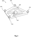
- Fig. 2 is an example figure showing tag 200, arranged in accordance with some embodiments of the present disclosure.
- Tag 200 may correspond to tag 121 of Fig. 1 .
- tag 200 includes point 201, point 202, point 203, point 204, point 205 and identification pattern 209.
- Points 201, 202, 203, 204, 205 and identification pattern 209 may emit lights having specific wavelengths which can be captured by an optical apparatus (e.g., optical apparatus 143). On the contrary, other parts of tag 200 emit very few such lights and therefore may be barely captured by the optical apparatus.
- an optical apparatus e.g., optical apparatus 143
- points 201, 202, 203, 204, 205 and identification pattern 209 may reflect lights generated by a light source having specific wavelengths which can be captured by an optical apparatus (e.g., optical apparatus 143). Other parts of tag 200 may absorb such lights and therefore may be barely captured by the optical apparatus.
- optical apparatus e.g., optical apparatus 143
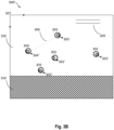
- Fig. 3A is an example image 300 of a tag captured by an optical apparatus, arranged in accordance with some embodiments of the present disclosure.
- Image 300 may include point images 301, 302, 303, 304 and 305, bar image 306 between points images 304 and 305 and identification image 309. It has been a challenge to associate point images 301, 302, 303, 304 and 305 to points 201, 202, 203, 204 and 205 efficiently and correctly.
- point image 301 may correspond to an image of point 201.
- point image 302 may correspond to an image of point 202
- point image 303 may correspond to an image of point 203
- point image 304 may correspond to an image of point 204
- point image 305 may correspond to an image of point 205.
- Bar image 306 may correspond to parts of tag 200 between points 204 and 205.
- Identification image 309 may correspond to identification pattern 209.
- Fig. 3B is an example processed image 300' of a tag captured by an optical apparatus
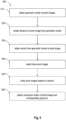
- Fig. 4 is a flow diagram illustrating an example process 400 to process a two-dimensional image associated with a tag, all arranged in accordance with some embodiments of the present disclosure.
- Process 400 may include one or more operations, functions, or actions as illustrated by blocks 410, 420 and/or 430, which may be performed by hardware, software and/or firmware.
- the various blocks are not intended to be limiting to the described embodiments.
- the outlined steps and operations are only provided as examples, and some of the steps and operations may be optional, combined into fewer steps and operations, or expanded into additional steps and operations without detracting from the essence of the disclosed embodiments.
- the blocks are illustrated in a sequential order, these blocks may also be performed in parallel, and/or in a different order than those described herein.
- Fig. 4 will be further described in details below.
- Image 300 is a two-dimensional image associated with tag 200.
- image 300' may be a processed image 300.
- a two-dimensional coordinate system is assigned to image 300'.
- the upper left corner 307 is assigned as the origin point (0, 0) of the two-dimensional coordinate system.
- the two-dimensional coordinate system may be based on pixels of image 300. Therefore, point images 301, 302, 303, 304 and 305 on image 300 may be described by the two-dimensional coordinate system.
- Block 410 may be followed by block 420 "identify coordinates associated with point images.”
- thresholding techniques may be applied. For example, image 300' is first processed with blocks including many pixels. In some embodiments, blocks not including any pixel having an intensity greater than a threshold (e.g., region 310 or bar image 306) are discarded from further processing to save the computation resources. Blocks including pixels having an intensity greater than the threshold (e.g., region 320) are then further processed on a pixel basis.
- a threshold e.g., region 310 or bar image 306
- region 320 may be enlarged with an enlargement factor. Therefore, point images 301, 302, 303, 304 and 305 may be also enlarged with the enlargement factor.
- additional thresholding techniques may be applied to pixels of the enlarged point images to identify one or more pixels that have a greater intensity. Image associated with the identified pixels may be shrunk back to the two-dimensional system based on a shrinkage factor (e.g., reciprocal of the enlargement factor). Therefore, new point images 301', 302', 303', 304' and 305' with higher intensity may be identified on image 300 and coordinates of the two-dimensional coordinate system may be assigned to point images 301', 302', 303', 304' and 305'.
- a shrinkage factor e.g., reciprocal of the enlargement factor
- point image 301' is assigned coordinates (X 301 ' , Y 301 ' ) on the two-dimensional coordinate system.
- point image 302' is assigned coordinates (X 302' , Y 302' )
- point image 303' is assigned coordinates (X 303' , Y 303' )
- point image 304' is assigned coordinates (X 304' , Y 304' )
- point image 305' is assigned coordinates (X 305' , Y 305' ), respectively.
- Block 420 may be followed by block 430 "associate point images with tag points.”
- point images 301', 302', 303', 304' and 305' are associated with points 201, 202, 203, 204 and 205.
- coordinates of point images 301', 302', 303', 304' and 305' on the two-dimensional coordinate system and coordinates of points 201, 202, 203, 204 and 205 of tag 121 on a three-dimensional coordinate system which describes the spatial relationship among optical apparatus 143, robotic arm assembly 140 and surgical instrument 141 a conversion matrix describing a relationship between a point image in image 300' and its associated point at tag 200 may be established.
- Fig. 5 is a flow diagram illustrating an example process 500 to associate point images with points of a tag, arranged in accordance with some embodiments of the present disclosure.
- Process 500 may include one or more operations, functions, or actions as illustrated by blocks 510, 520, 530, 540, 550 and/or 560, which may be performed by hardware, software and/or firmware.
- the various blocks are not intended to be limiting to the described embodiments.
- the outlined steps and operations are only provided as examples, and some of the steps and operations may be optional, combined into fewer steps and operations, or expanded into additional steps and operations without detracting from the essence of the disclosed embodiments.
- the blocks are illustrated in a sequential order, these blocks may also be performed in parallel, and/or in a different order than those described herein.
- Process 500 may begin at block 510, "obtain geometric center of point images.”
- point images 301', 302', 303', 304' and 305' have coordinates (X 301' , Y 301' ), (X 302' , Y 302' ), (X 303' , Y 303' ), (X 304' , Y 304' ) and (X 305' , Y 305' ), respectively.
- a geometric center of point images 301', 302', 303', 304' and 305' may have coordinates ((X 301' + X 302' + X 303' + X 304' + X 305' )/5, (Y 301' + Y 302' + Y 303' + Y 304' + Y 305 ')/5).
- Block 510 may be followed by block 520, "obtain distance of point image from geometric center.”
- a first distance between point image 301' and the geometric center is obtained as X 301 ′ ⁇ X 301 ′ + X 302 ′ + X 303 ′ + X 304 ′ + X 305 ′ 5 2 + Y 301 ′ ⁇ Y 301 ′ + Y 302 ′ + Y 303 ′ + Y 304 ′ + Y 305 ′ 5 2 .
- a second distance between point image 302' and the geometric center, a third distance between point image 303' and the geometric center, a fourth distance between point image 304' and the geometric center and a fifth distance between point image 305' and the geometric center may be obtained.
- Block 520 may be followed by block 530, "obtain vector from geometric center to point image.”
- a first vector Geometr ⁇ c center 301 ′ ⁇ from the geometric center to point image 301' is obtained as (X 301' - (X 301' + X 302' + X 303' + X 304' + X 305' )/5, Y 301 ' -(Y 301' + Y 302' + Y 303' + Y 304' + Y 305' )/5).
- a second vector Geometr ⁇ c center 302 ′ ⁇ from the geometric center to point image 302', a third vector Geometr ⁇ c center 303 ′ ⁇ from the geometric center to point image 303', a fourth vector Geometr ⁇ c center 304 ′ ⁇ from the geometric center to point image 304' and a fifth vector Geometr ⁇ c center 304 ′ ⁇ from the geometric center to point image 305' may be also obtained.
- Block 530 may be followed by block 540, "select base point image.”
- the first distance, the second distance, the third distance, the fourth distance and the fifth distance obtained in block 520 are compared to select which point image is the base point image.
- the point image having the farthest distance from the geometric center in the two-dimensional coordinate system may be selected as the base point.
- the point image having the closest distance from the geometric center in the two-dimensional coordinate system may be selected as the base point.
- the base point may be selected based on a relationship between identification image 309 and point images 301', 302', 303', 304' and 305' in the two-dimensional coordinate system. For illustration only, in some embodiments, point image 301' is selected as the base point image.
- Block 540 may be followed by block 550, "index point images based on vectors.”
- a cross product of the first vector (e.g., Geometr ⁇ c center 301 ′ ⁇ ) and the second vector (e.g., Geometr ⁇ c center 302 ′ ⁇ ) may be used to determine whether point image 302' is along the clockwise direction from point image 301'.
- point image 302' is determined along the clockwise direction from point image 301'.
- a dot product of the first vector (e.g., Geometr ⁇ c center 301 ′ ⁇ ) and the second vector (e.g., Geometr ⁇ c center 302 ′ ⁇ ) may be used to determine an angle between the first vector and the second vector. Therefore, based on the cross product and the dot product, point image 302' may be determined at a first angle along the clockwise direction from point image 301'. Similarly, point images 303', 304' and 305' may be determined at a second angle, a third angle and a fourth angle along the clockwise direction from point image 301', respectively.
- a sequence of point images 301', 302', 303', 304' and 305' along the clockwise direction may be determined. For example, in response to the first angle is smaller than the second angle, point image 302' is determined to be closer to point image 301' along the clockwise direction than point 303'. After the sequence is determined, point images 301', 302', 303', 304' and 305' may be indexed according to the sequence.
- Block 550 may be followed by block 560, "obtain conversion matrix of point image and corresponding tag point.”
- a conversion matrix which describes a mathematical relationship between coordinates of points of tag 200 (e.g., 201, 202, 203, 204 and 205) in a three-dimensional coordinate system and their corresponding point image (e.g., 301', 302', 303', 304' and 305') may be established.
- the three-dimensional coordinate system may describe the spatial relationship among optical apparatus 143, robotic arm assembly 140 and surgical instrument 141.
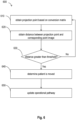
- Fig. 6 is a flow diagram illustrating an example process 600 to update an operation pathway in response to a movement of a patient based on a plurality of conversion matrices, arranged in accordance with some embodiments of the present disclosure.
- Process 600 may include one or more operations, functions, or actions as illustrated by blocks 610, 620, 630, 640 and/or 650, which may be performed by hardware, software and/or firmware.
- the various blocks are not intended to be limiting to the described embodiments.
- the outlined steps and operations are only provided as examples, and some of the steps and operations may be optional, combined into fewer steps and operations, or expanded into additional steps and operations without detracting from the essence of the disclosed embodiments.
- the blocks are illustrated in a sequential order, these blocks may also be performed in parallel, and/or in a different order than those described herein.
- Process 600 may begin at block 610, "obtain projection point based on conversion matrix.”
- a first projection point of point 201 according to the conversion matrix may be obtained.
- the projection point has coordinates (X 301" , Y 301 " ) in the two-dimensional coordinate system.
- a second projection point of point 202, a third projection point of point 203, a fourth projection point of point 204 and a fifth projection point of point 205 may also be obtained and has coordinates (X 302" , Y 302" ), (X 303" , Y 303" ), (X 304" , Y 304" ) and (X 305" , Y 305" ) in the two-dimensional coordinate system, respectively.
- Block 610 may be followed by block 620, "obtain distance between projection point and corresponding point image.”
- a first distance between the first projection point having coordinates (X 301" , Y 301" ) and point image 301' having coordinates (X 301' , Y 301' ) is calculated.
- a second distance between the second projection point having coordinates (X 302" , Y 302" ) and point image 302' having coordinates (X 302' , Y 302' ), a third distance between the second projection point having coordinates (X 303" , Y 303" ) and point image 303' having coordinates (X 303' , Y 303' ), a fourth distance between the fourth projection point having coordinates (X 304" , Y 304" ) and point image 304' having coordinates (X 304' , Y 304' ) and a fifth distance between the fifth projection point having coordinates (X 305" , Y 305" ) and point image 305' having coordinates (X 305' , Y 305' ) may be also obtained, respectively.
- Block 620 may be followed by block 630, "distance greater than threshold?"
- block 630 in response to a sum of the first distance, the second distance, the third distance, the fourth distance and the fifth distance is greater than a threshold, block 630 may be followed by block 640, "determine patient is moved.”
- block 630 in response to a sum of the first distance, the second distance, the third distance, the fourth distance and the fifth distance not greater than a threshold, block 630 may be followed by block 610, "obtain projection point based on conversion matrix.” After obtaining another conversion matrix associated with image 300/300' captured at a second time, another set of projection points having coordinates in the two-dimensional coordinate system of points 201, 202, 203, 204 and 205 may be obtained according to another conversion matrix.
- Block 640 may be followed by block 650, "update operation pathway.”
- robotic arm assembly 140 may move to a safety point which will not cause harms to patient 110.
- a new operation pathway may be updated in response to the movement of patient 110 and robotic arm assembly 140 is then configured to move from the safety point along the updated operation pathway.
- the updated operation pathway may be verified so that the updated operation pathway will not cause a collision between surgical instrument 141 and robotic arm assembly 140.
- the updated operation pathway may be verified so that the updated operation pathway will not cause a collision among first arm 147, second arm 148 and third arm 149 of robotic arm assembly 140.
- the updated operation pathway In response to the updated operation pathway is verified to cause a collision of robotic arm assembly 140, the updated operation pathway will be abandoned and a new updated operation pathway will be calculated.
- Examples of a signal bearing medium include, but are not limited to, the following: a recordable type medium such as a floppy disk, a hard disk drive, a Compact Disc (CD), a Digital Versatile Disk (DVD), a digital tape, a computer memory, etc.; and a transmission type medium such as a digital and/or an analog communication medium (e.g., a fiber optic cable, a waveguide, a wired communications link, a wireless communication link, etc.).
Landscapes
- Health & Medical Sciences (AREA)
- Surgery (AREA)
- Life Sciences & Earth Sciences (AREA)
- Engineering & Computer Science (AREA)
- Animal Behavior & Ethology (AREA)
- General Health & Medical Sciences (AREA)
- Biomedical Technology (AREA)
- Heart & Thoracic Surgery (AREA)
- Medical Informatics (AREA)
- Molecular Biology (AREA)
- Nuclear Medicine, Radiotherapy & Molecular Imaging (AREA)
- Veterinary Medicine (AREA)
- Public Health (AREA)
- Robotics (AREA)
- Oral & Maxillofacial Surgery (AREA)
- Pathology (AREA)
- Apparatus For Radiation Diagnosis (AREA)
- Manipulator (AREA)
- Image Processing (AREA)
- Image Analysis (AREA)
Claims (9)
- Verfahren zum Aktualisieren eines Operationspfads für eine Roboterarmanordnung (140) zum Durchführen einer Operation an einem Patienten (110) mit einer vorbestimmten räumlichen Beziehung zu einem Rahmen (120), der ein Kennzeichen (121, 200) beinhaltet, als Reaktion auf eine Bewegung des Patienten (100), umfassend:Verarbeiten eines zweidimensionalen (300) Bildes, das mit dem Kennzeichen (121, 200) assoziiert ist, das die räumliche Beziehung zu dem Patienten (110) aufweist, wobei eine entsprechende Bewegung des Kennzeichens (121, 200) als Reaktion auf die Bewegung des Patienten basierend auf der räumlichen Beziehung bestimmt wird, und wobei das Kennzeichen (121, 200) einen ersten Punkt (201) und einen zweiten Punkt (202) beinhaltet und das zweidimensionale Bild (300) ein erstes Punktbild (301) und ein zweites Punktbild (302) beinhaltet;Assoziieren des ersten Punktbildes (301) mit dem ersten Punkt (201) und des zweiten Punktbildes (302) mit dem zweiten Punkt (202); undIdentifizieren der Bewegung des Patienten (110) und Aktualisieren des Operationspfads, daurch gekennzeichnet, dass das Verfahren das Verwenden einer Umwandlungsmatrix umfasst, die eine mathematische Beziehung zwischen Koordinaten des ersten und zweiten Punkts (201, 202) des Kennzeichens (121, 200) in einem dreidimensionalen Koordinatensystem und ihren entsprechenden ersten und zweiten Punktbildern (301, 303) beschreibt;und dadurch, dass das Verarbeiten des zweidimensionalen Bildes (300) Folgendes umfasst:Verwerfen von Blöcken (310), die kein Pixel beinhalten, das eine Intensität aufweist, die größer als ein Schwellenwert ist, aus der weiteren Verarbeitung, undVergrößern eines Bereichs (320), der das erste und zweite Punktbild (301, 302) beinhaltet, mit einem Vergrößerungsfaktor, Anwenden zusätzlicher Schwellenwerttechniken auf das vergrößerte erste und zweite Punktbild, um ein oder mehrere Pixel zu identifizieren, die eine größere Intensität aufweisen, und Verkleinern des Bildes mit den identifizierten Pixeln zurück basierend auf einem Verkleinerungsfaktor, wodurch neue erste und zweite Punktbilder (301', 302') mit höherer Intensität bereitgestellt werden.
- Verfahren nach Anspruch 1, wobei das Verarbeiten des zweidimensionalen Bildes (300) ferner das Zuweisen eines zweidimensionalen Koordinatensystems zu dem zweidimensionalen Bild und das Identifizieren von Koordinaten, die dem ersten Punktbild (301) und dem zweiten Punktbild (302) in dem zweidimensionalen Koordinatensystem zugeordnet sind, beinhaltet.
- Verfahren nach Anspruch 1, wobei das Zuordnen des ersten Punktbildes (301) zu dem ersten Punkt (201) ferner Folgendes umfasst:Erhalten eines geometrischen Zentrums, das dem ersten Punktbild (301) und dem zweiten Punktbild (302) in dem zweidimensionalen Koordinatensystem zugeordnet ist;Erhalten eines ersten Abstands zwischen dem ersten Punktbild (301) und dem geometrischen Zentrum und eines zweiten Abstands zwischen dem zweiten Punktbild (302) und dem geometrischen Zentrum; undAuswählen eines des ersten und des zweiten Punktbildes als ein Basispunktbild basierend auf einem Vergleich des ersten Abstands und des zweiten Abstands.
- Verfahren nach Anspruch 1, wobei das Aktualisieren des Operationspfads ferner Folgendes beinhaltet:Erhalten eines ersten Projektionspunkts, der dem ersten Punkt zugeordnet ist, und eines zweiten Projektionspunkts, der dem zweiten Punkt zugeordnet ist, in dem zweidimensionalen Koordinatensystem unter Verwendung der Umwandlungsmatrix;Erhalten eines dritten Abstands zwischen dem ersten Projektionspunkt und dem ersten Punktbild in dem zweidimensionalen Koordinatensystem; undErhalten eines vierten Abstands zwischen dem zweiten Projektionspunkt und dem zweiten Punktbild in dem zweidimensionalen Koordinatensystem,wobei das Verfahren vorzugsweise ferner als Reaktion darauf, dass eine Summe des dritten Abstands und des vierten Abstands größer als ein zweiter Schwellenwert ist, das Identifizieren der Bewegung des Patienten und das Aktualisieren des Operationspfads umfasst,wobei das Verfahren vorzugsweise ferner Folgendes umfasst:
als Reaktion auf das Identifizieren der Bewegung des Patienten, Bewegen der Roboterarmanordnung (140) zu einem Sicherheitspunkt. - System (100) zum Aktualisieren eines Operationspfads für eine Roboterarmanordnung (140) zum Durchführen einer Operation an einem Patienten (110) mit einer vorbestimmten räumlichen Beziehung zu einem Rahmen (120), der ein Kennzeichen (121, 200) beinhaltet, als Reaktion auf eine Bewegung des Patienten (110), wobei das System (100) Folgendes umfasst:den Rahmen (120), der das Kennzeichen (121, 200) beinhaltet;die Roboterarmanordnung (140), die eine optische Vorrichtung (143) zum Erfassen eines zweidimensionalen Bildes (300) des Kennzeichens (121, 200) beinhaltet; undeinen Prozessor, der der Roboterarmanordnung (140) zugeordnet ist, wobei der Prozessor zum Aktualisieren des Operationspfads der Roboterarmanordnung (140) dient;wobei der Prozessor für Folgendes konfiguriert ist:Verarbeiten des zweidimensionalen Bildes (300), das dem Kennzeichen (121, 200) zugeordnet ist, wobei das Kennzeichen (121, 200) einen ersten Punkt (201) und einen zweiten Punkt (202) beinhaltet und das zweidimensionale Bild ein erstes Punktbild (301) und ein zweites Punktbild (302) beinhaltet;Assoziieren des ersten Punktbildes (301) mit dem ersten Punkt (201) und des zweiten Punktbildes (302) mit dem zweiten Punkt (202); undIdentifizieren der Bewegung des Patienten und Aktualisieren des Operationspfads, daurch gekennzeichnet, dass der Prozessor zum Verwenden einer Umwandlungsmatrix konfiguriert ist, die eine mathematische Beziehung zwischen Koordinaten des ersten und zweiten Punkts (201, 202) des Kennzeichens (121, 200) in einem dreidimensionalen Koordinatensystem und ihren entsprechenden ersten und zweiten Punktbildern (301, 303) beschreibt;und dadurch, dass der Prozessor zum Ausführen einer Verarbeitung des zweidimensionalen Bildes (300) konfiguriert ist, die Folgendes umfasst:Verwerfen von Blöcken (310), die kein Pixel beinhalten, das eine Intensität aufweist, die größer als ein Schwellenwert ist, aus der weiteren Verarbeitung, undVergrößern eines Bereichs (320), der das erste und zweite Punktbild (301, 302) beinhaltet, mit einem Vergrößerungsfaktor, Anwenden zusätzlicher Schwellenwerttechniken auf das vergrößerte erste und zweite Punktbild, um ein oder mehrere Pixel zu identifizieren, die eine größere Intensität aufweisen, und Verkleinern des Bildes mit den identifizierten Pixeln zurück basierend auf einem Verkleinerungsfaktor, wodurch neue erste und zweite Punktbilder (301', 302') mit höherer Intensität bereitgestellt werden.
- System (100) nach Anspruch 5, wobei der Prozessor ferner zum Zuweisen eines zweidimensionalen Koordinatensystems zu dem zweidimensionalen Bild und zum Identifizieren von Koordinaten, die dem ersten Punktbild und dem zweiten Punktbild in dem zweidimensionalen Koordinatensystem zugeordnet sind, konfiguriert ist.
- System (100) nach Anspruch 5, wobei der Prozessor ferner für Folgendes konfiguriert ist:Erhalten eines geometrischen Zentrums, das dem ersten Punktbild (301) und dem zweiten Punktbild (302) in dem zweidimensionalen Koordinatensystem zugeordnet ist;Erhalten eines ersten Abstands zwischen dem ersten Punktbild (301) und dem geometrischen Zentrum und eines zweiten Abstands zwischen dem zweiten Punktbild (302) und dem geometrischen Zentrum; undAuswählen eines des ersten und des zweiten Punktbildes als ein Basispunktbild basierend auf einem Vergleich des ersten Abstands und des zweiten Abstands.
- System (100) nach Anspruch 5, wobei der Prozessor ferner für Folgendes konfiguriert ist:Erhalten eines ersten Projektionspunkts, der dem ersten Punkt zugeordnet ist, und eines zweiten Projektionspunkts, der dem zweiten Punkt zugeordnet ist, in dem zweidimensionalen Koordinatensystem unter Verwendung der Umwandlungsmatrix;Erhalten eines dritten Abstands zwischen dem ersten Projektionspunkt und dem ersten Punktbild in dem zweidimensionalen Koordinatensystem; undErhalten eines vierten Abstands zwischen dem zweiten Projektionspunkt und dem zweiten Punktbild in dem zweidimensionalen Koordinatensystem.
- Nichtflüchtiges computerlesbares Speichermedium, dadurch gekennzeichnet, dass das nichtflüchtige computerlesbare Speichermedium einen Satz ausführbarer Anweisungen enthält, die als Reaktion auf die Ausführung durch einen Prozessor bewirken, dass der Prozessor ein Verfahren nach einem der Ansprüche 1 bis 3 durchführt.
Priority Applications (1)
| Application Number | Priority Date | Filing Date | Title |
|---|---|---|---|
| EP25169017.8A EP4555968A3 (de) | 2018-08-01 | 2019-07-31 | Verfahren und system zur aktualisierung eines betriebspfades für eine roboterarmanordnung. |
Applications Claiming Priority (3)
| Application Number | Priority Date | Filing Date | Title |
|---|---|---|---|
| US201862713522P | 2018-08-01 | 2018-08-01 | |
| US201962820804P | 2019-03-19 | 2019-03-19 | |
| PCT/CN2019/098706 WO2020025001A1 (en) | 2018-08-01 | 2019-07-31 | Method and system of tracking patient position in operation |
Related Child Applications (1)
| Application Number | Title | Priority Date | Filing Date |
|---|---|---|---|
| EP25169017.8A Division EP4555968A3 (de) | 2018-08-01 | 2019-07-31 | Verfahren und system zur aktualisierung eines betriebspfades für eine roboterarmanordnung. |
Publications (4)
| Publication Number | Publication Date |
|---|---|
| EP3829476A1 EP3829476A1 (de) | 2021-06-09 |
| EP3829476A4 EP3829476A4 (de) | 2022-04-20 |
| EP3829476C0 EP3829476C0 (de) | 2025-04-09 |
| EP3829476B1 true EP3829476B1 (de) | 2025-04-09 |
Family
ID=69231442
Family Applications (2)
| Application Number | Title | Priority Date | Filing Date |
|---|---|---|---|
| EP19844408.5A Active EP3829476B1 (de) | 2018-08-01 | 2019-07-31 | Verfahren und system zum aktualisieren eines betriebswegs für eine roboterarmbaugruppe. |
| EP25169017.8A Pending EP4555968A3 (de) | 2018-08-01 | 2019-07-31 | Verfahren und system zur aktualisierung eines betriebspfades für eine roboterarmanordnung. |
Family Applications After (1)
| Application Number | Title | Priority Date | Filing Date |
|---|---|---|---|
| EP25169017.8A Pending EP4555968A3 (de) | 2018-08-01 | 2019-07-31 | Verfahren und system zur aktualisierung eines betriebspfades für eine roboterarmanordnung. |
Country Status (8)
| Country | Link |
|---|---|
| US (1) | US11998279B2 (de) |
| EP (2) | EP3829476B1 (de) |
| JP (1) | JP7457692B2 (de) |
| KR (1) | KR102488901B1 (de) |
| CN (1) | CN112770686B (de) |
| CA (1) | CA3107892C (de) |
| TW (1) | TWI733151B (de) |
| WO (1) | WO2020025001A1 (de) |
Families Citing this family (2)
| Publication number | Priority date | Publication date | Assignee | Title |
|---|---|---|---|---|
| CN114429214B (zh) | 2020-10-29 | 2025-08-01 | 阿里巴巴集团控股有限公司 | 运算单元、相关装置和方法 |
| CN117243699B (zh) * | 2023-11-14 | 2024-03-15 | 杭州三坛医疗科技有限公司 | 一种移位检测方法及装置 |
Family Cites Families (33)
| Publication number | Priority date | Publication date | Assignee | Title |
|---|---|---|---|---|
| US6973202B2 (en) * | 1998-10-23 | 2005-12-06 | Varian Medical Systems Technologies, Inc. | Single-camera tracking of an object |
| US9867669B2 (en) * | 2008-12-31 | 2018-01-16 | Intuitive Surgical Operations, Inc. | Configuration marker design and detection for instrument tracking |
| US9782229B2 (en) * | 2007-02-16 | 2017-10-10 | Globus Medical, Inc. | Surgical robot platform |
| CN101467887B (zh) * | 2007-12-29 | 2011-04-27 | 复旦大学 | 一种手术导航系统中x射线透视图像标定方法 |
| CN101697869B (zh) * | 2009-10-19 | 2011-06-15 | 沈国芳 | 手术导航用固定支架 |
| US20130072784A1 (en) * | 2010-11-10 | 2013-03-21 | Gnanasekar Velusamy | Systems and methods for planning image-guided interventional procedures |
| FR2983059B1 (fr) | 2011-11-30 | 2014-11-28 | Medtech | Procede assiste par robotique de positionnement d'instrument chirurgical par rapport au corps d'un patient et dispositif de mise en oeuvre. |
| CN102551892A (zh) * | 2012-01-17 | 2012-07-11 | 王旭东 | 一种用于颅颌面外科手术的定位方法 |
| JP6262216B2 (ja) * | 2012-06-01 | 2018-01-17 | インテュイティブ サージカル オペレーションズ, インコーポレイテッド | 零空間を使用して操作アーム間の衝突を回避するためのシステム及び方法 |
| US20190000569A1 (en) * | 2012-06-21 | 2019-01-03 | Globus Medical, Inc. | Controlling a surgical robot to avoid robotic arm collision |
| US11116576B2 (en) * | 2012-06-21 | 2021-09-14 | Globus Medical Inc. | Dynamic reference arrays and methods of use |
| KR101993384B1 (ko) * | 2012-10-24 | 2019-06-26 | 삼성전자주식회사 | 환자의 자세 변화에 따른 의료 영상을 보정하는 방법, 장치 및 시스템 |
| KR101446173B1 (ko) * | 2013-02-21 | 2014-10-01 | 주식회사 고영테크놀러지 | 트랙킹 시스템 및 이를 이용한 트랙킹 방법 |
| US11278353B2 (en) * | 2016-03-16 | 2022-03-22 | Synaptive Medical Inc. | Trajectory alignment system and methods |
| BR112015023547B8 (pt) * | 2013-03-15 | 2022-09-27 | Synaptive Medical Inc | Montagem de braço automatizado para uso usado durante um procedimento médico sobre uma parte anatômica |
| US9993222B2 (en) * | 2014-02-05 | 2018-06-12 | Intuitive Surgical Operations, Inc. | System and method for dynamic virtual collision objects |
| CN104083217B (zh) | 2014-07-03 | 2016-08-17 | 北京天智航医疗科技股份有限公司 | 一种手术定位装置以及机器人手术系统 |
| US9950194B2 (en) * | 2014-09-09 | 2018-04-24 | Mevion Medical Systems, Inc. | Patient positioning system |
| CA2964512C (en) * | 2014-10-14 | 2018-04-24 | Synaptive Medical (Barbados) Inc. | Patient reference tool |
| US10413377B2 (en) * | 2015-03-19 | 2019-09-17 | Medtronic Navigation, Inc. | Flexible skin based patient tracker for optical navigation |
| US10143523B2 (en) * | 2015-03-31 | 2018-12-04 | 7D Surgical Inc. | Systems, methods and devices for tracking and calibration of flexible instruments |
| KR102371053B1 (ko) * | 2015-06-04 | 2022-03-10 | 큐렉소 주식회사 | 수술로봇 시스템 |
| EP3145420B8 (de) * | 2015-06-05 | 2020-12-30 | Brain Navi Biotechnology Co., Ltd. | Intraoperatives verfolgungsverfahren |
| CN108472095B (zh) * | 2015-12-29 | 2021-11-02 | 皇家飞利浦有限公司 | 用于机器人外科手术的使用虚拟现实设备的系统、控制器和方法 |
| CN107468350B (zh) * | 2016-06-08 | 2020-12-08 | 北京天智航医疗科技股份有限公司 | 一种三维图像专用标定器、手术定位系统及定位方法 |
| CN107468351A (zh) * | 2016-06-08 | 2017-12-15 | 北京天智航医疗科技股份有限公司 | 一种手术定位装置、定位系统及定位方法 |
| KR101861176B1 (ko) * | 2016-08-16 | 2018-05-28 | 주식회사 고영테크놀러지 | 정위수술용 수술로봇 및 정위수술용 수술로봇의 제어방법 |
| CN106236258B (zh) | 2016-08-17 | 2019-03-12 | 北京柏惠维康科技有限公司 | 腹腔微创手术穿刺路径的规划方法及装置 |
| EP3375399B1 (de) * | 2016-10-05 | 2022-05-25 | NuVasive, Inc. | Chirurgisches navigationssystem |
| FR3057757B1 (fr) * | 2016-10-21 | 2021-04-16 | Medtech | Dispositif et procede de recalage automatique pour des images intra operatoires 3d |
| US11751948B2 (en) * | 2016-10-25 | 2023-09-12 | Mobius Imaging, Llc | Methods and systems for robot-assisted surgery |
| CN106890025B (zh) | 2017-03-03 | 2020-02-28 | 浙江大学 | 一种微创手术导航系统和导航方法 |
| GB2577718B (en) * | 2018-10-03 | 2022-08-24 | Cmr Surgical Ltd | Feature identification |
-
2019
- 2019-07-31 KR KR1020217006130A patent/KR102488901B1/ko active Active
- 2019-07-31 CA CA3107892A patent/CA3107892C/en active Active
- 2019-07-31 EP EP19844408.5A patent/EP3829476B1/de active Active
- 2019-07-31 US US17/263,855 patent/US11998279B2/en active Active
- 2019-07-31 WO PCT/CN2019/098706 patent/WO2020025001A1/en not_active Ceased
- 2019-07-31 EP EP25169017.8A patent/EP4555968A3/de active Pending
- 2019-07-31 TW TW108127112A patent/TWI733151B/zh active
- 2019-07-31 JP JP2021505301A patent/JP7457692B2/ja active Active
- 2019-07-31 CN CN201980051025.5A patent/CN112770686B/zh active Active
Also Published As
| Publication number | Publication date |
|---|---|
| KR20210057724A (ko) | 2021-05-21 |
| EP3829476C0 (de) | 2025-04-09 |
| JP7457692B2 (ja) | 2024-03-28 |
| JP2021532882A (ja) | 2021-12-02 |
| CN112770686A (zh) | 2021-05-07 |
| CN112770686B (zh) | 2024-08-02 |
| EP3829476A1 (de) | 2021-06-09 |
| KR102488901B1 (ko) | 2023-01-17 |
| TWI733151B (zh) | 2021-07-11 |
| CA3107892A1 (en) | 2020-02-06 |
| EP4555968A3 (de) | 2025-08-13 |
| EP4555968A2 (de) | 2025-05-21 |
| TW202023488A (zh) | 2020-07-01 |
| US11998279B2 (en) | 2024-06-04 |
| CA3107892C (en) | 2023-09-05 |
| WO2020025001A1 (en) | 2020-02-06 |
| US20210307832A1 (en) | 2021-10-07 |
| EP3829476A4 (de) | 2022-04-20 |
Similar Documents
| Publication | Publication Date | Title |
|---|---|---|
| US10789739B2 (en) | System and method for generating partial surface from volumetric data for registration to surface topology image data | |
| KR102729989B1 (ko) | 수술 내비게이션을 위한 장애물 회피 기술 | |
| JP6525977B2 (ja) | コンピュータ支援外科手術装置および組織切断方法 | |
| US9119670B2 (en) | System and methods for intraoperative guidance feedback | |
| US7561733B2 (en) | Patient registration with video image assistance | |
| CN107753105A (zh) | 定位手术用手术机器人系统及其控制方法 | |
| US20220071708A1 (en) | Patient positioning using a skeleton model | |
| US20200008892A1 (en) | Method and system of determining one or more points on operation pathway | |
| EP3829476B1 (de) | Verfahren und system zum aktualisieren eines betriebswegs für eine roboterarmbaugruppe. | |
| Meng et al. | An automatic markerless registration method for neurosurgical robotics based on an optical camera | |
| CN116725674A (zh) | 三维实时图像的追踪方法、装置及存储介质 | |
| EP3941379B1 (de) | Verfahren und system zur bestimmung des operationsweges basierend auf einem bildabgleich | |
| CN117357143A (zh) | 一种可自主移动的双机械臂数字化x线摄影系统及装置 | |
| KR102577964B1 (ko) | 간 수술을 위한 정렬 시스템 | |
| CN121587839A (zh) | C形臂的导航方法、系统、装置、手术导航设备、可读存储介质和程序产品 | |
| Ozturk | Rat brain variability, utility of it's surface for guiding alignment and development of a structured light based brain surface scanner |
Legal Events
| Date | Code | Title | Description |
|---|---|---|---|
| STAA | Information on the status of an ep patent application or granted ep patent |
Free format text: STATUS: THE INTERNATIONAL PUBLICATION HAS BEEN MADE |
|
| PUAI | Public reference made under article 153(3) epc to a published international application that has entered the european phase |
Free format text: ORIGINAL CODE: 0009012 |
|
| STAA | Information on the status of an ep patent application or granted ep patent |
Free format text: STATUS: REQUEST FOR EXAMINATION WAS MADE |
|
| 17P | Request for examination filed |
Effective date: 20210201 |
|
| AK | Designated contracting states |
Kind code of ref document: A1 Designated state(s): AL AT BE BG CH CY CZ DE DK EE ES FI FR GB GR HR HU IE IS IT LI LT LU LV MC MK MT NL NO PL PT RO RS SE SI SK SM TR |
|
| DAV | Request for validation of the european patent (deleted) | ||
| DAX | Request for extension of the european patent (deleted) | ||
| A4 | Supplementary search report drawn up and despatched |
Effective date: 20220322 |
|
| RIC1 | Information provided on ipc code assigned before grant |
Ipc: A61B 90/00 20160101ALI20220316BHEP Ipc: A61B 17/00 20060101ALI20220316BHEP Ipc: A61B 34/30 20160101ALI20220316BHEP Ipc: A61B 34/00 20160101ALI20220316BHEP Ipc: A61B 34/20 20160101AFI20220316BHEP |
|
| GRAP | Despatch of communication of intention to grant a patent |
Free format text: ORIGINAL CODE: EPIDOSNIGR1 |
|
| STAA | Information on the status of an ep patent application or granted ep patent |
Free format text: STATUS: GRANT OF PATENT IS INTENDED |
|
| INTG | Intention to grant announced |
Effective date: 20241031 |
|
| GRAS | Grant fee paid |
Free format text: ORIGINAL CODE: EPIDOSNIGR3 |
|
| GRAA | (expected) grant |
Free format text: ORIGINAL CODE: 0009210 |
|
| STAA | Information on the status of an ep patent application or granted ep patent |
Free format text: STATUS: THE PATENT HAS BEEN GRANTED |
|
| AK | Designated contracting states |
Kind code of ref document: B1 Designated state(s): AL AT BE BG CH CY CZ DE DK EE ES FI FR GB GR HR HU IE IS IT LI LT LU LV MC MK MT NL NO PL PT RO RS SE SI SK SM TR |
|
| REG | Reference to a national code |
Ref country code: GB Ref legal event code: FG4D |
|
| REG | Reference to a national code |
Ref country code: CH Ref legal event code: EP |
|
| REG | Reference to a national code |
Ref country code: DE Ref legal event code: R096 Ref document number: 602019068514 Country of ref document: DE |
|
| REG | Reference to a national code |
Ref country code: IE Ref legal event code: FG4D |
|
| U01 | Request for unitary effect filed |
Effective date: 20250509 |
|
| U07 | Unitary effect registered |
Designated state(s): AT BE BG DE DK EE FI FR IT LT LU LV MT NL PT RO SE SI Effective date: 20250516 |
|
| U20 | Renewal fee for the european patent with unitary effect paid |
Year of fee payment: 7 Effective date: 20250725 |
|
| PG25 | Lapsed in a contracting state [announced via postgrant information from national office to epo] |
Ref country code: ES Free format text: LAPSE BECAUSE OF FAILURE TO SUBMIT A TRANSLATION OF THE DESCRIPTION OR TO PAY THE FEE WITHIN THE PRESCRIBED TIME-LIMIT Effective date: 20250409 |
|
| PG25 | Lapsed in a contracting state [announced via postgrant information from national office to epo] |
Ref country code: GR Free format text: LAPSE BECAUSE OF FAILURE TO SUBMIT A TRANSLATION OF THE DESCRIPTION OR TO PAY THE FEE WITHIN THE PRESCRIBED TIME-LIMIT Effective date: 20250710 Ref country code: NO Free format text: LAPSE BECAUSE OF FAILURE TO SUBMIT A TRANSLATION OF THE DESCRIPTION OR TO PAY THE FEE WITHIN THE PRESCRIBED TIME-LIMIT Effective date: 20250709 |
|
| PG25 | Lapsed in a contracting state [announced via postgrant information from national office to epo] |
Ref country code: PL Free format text: LAPSE BECAUSE OF FAILURE TO SUBMIT A TRANSLATION OF THE DESCRIPTION OR TO PAY THE FEE WITHIN THE PRESCRIBED TIME-LIMIT Effective date: 20250409 |
|
| PG25 | Lapsed in a contracting state [announced via postgrant information from national office to epo] |
Ref country code: HR Free format text: LAPSE BECAUSE OF FAILURE TO SUBMIT A TRANSLATION OF THE DESCRIPTION OR TO PAY THE FEE WITHIN THE PRESCRIBED TIME-LIMIT Effective date: 20250409 |
|
| PG25 | Lapsed in a contracting state [announced via postgrant information from national office to epo] |
Ref country code: RS Free format text: LAPSE BECAUSE OF FAILURE TO SUBMIT A TRANSLATION OF THE DESCRIPTION OR TO PAY THE FEE WITHIN THE PRESCRIBED TIME-LIMIT Effective date: 20250709 |
|
| PG25 | Lapsed in a contracting state [announced via postgrant information from national office to epo] |
Ref country code: IS Free format text: LAPSE BECAUSE OF FAILURE TO SUBMIT A TRANSLATION OF THE DESCRIPTION OR TO PAY THE FEE WITHIN THE PRESCRIBED TIME-LIMIT Effective date: 20250809 |
|
| PG25 | Lapsed in a contracting state [announced via postgrant information from national office to epo] |
Ref country code: SM Free format text: LAPSE BECAUSE OF FAILURE TO SUBMIT A TRANSLATION OF THE DESCRIPTION OR TO PAY THE FEE WITHIN THE PRESCRIBED TIME-LIMIT Effective date: 20250409 |
|
| PG25 | Lapsed in a contracting state [announced via postgrant information from national office to epo] |
Ref country code: CZ Free format text: LAPSE BECAUSE OF FAILURE TO SUBMIT A TRANSLATION OF THE DESCRIPTION OR TO PAY THE FEE WITHIN THE PRESCRIBED TIME-LIMIT Effective date: 20250409 |
|
| PG25 | Lapsed in a contracting state [announced via postgrant information from national office to epo] |
Ref country code: SK Free format text: LAPSE BECAUSE OF FAILURE TO SUBMIT A TRANSLATION OF THE DESCRIPTION OR TO PAY THE FEE WITHIN THE PRESCRIBED TIME-LIMIT Effective date: 20250409 |
|
| PLBE | No opposition filed within time limit |
Free format text: ORIGINAL CODE: 0009261 |
|
| STAA | Information on the status of an ep patent application or granted ep patent |
Free format text: STATUS: NO OPPOSITION FILED WITHIN TIME LIMIT |
|
| REG | Reference to a national code |
Ref country code: CH Ref legal event code: L10 Free format text: ST27 STATUS EVENT CODE: U-0-0-L10-L00 (AS PROVIDED BY THE NATIONAL OFFICE) Effective date: 20260218 |
|
| REG | Reference to a national code |
Ref country code: CH Ref legal event code: H13 Free format text: ST27 STATUS EVENT CODE: U-0-0-H10-H13 (AS PROVIDED BY THE NATIONAL OFFICE) Effective date: 20260224 |
|
| 26N | No opposition filed |
Effective date: 20260112 |
|
| GBPC | Gb: european patent ceased through non-payment of renewal fee |
Effective date: 20250731 |
|
| PG25 | Lapsed in a contracting state [announced via postgrant information from national office to epo] |
Ref country code: GB Free format text: LAPSE BECAUSE OF NON-PAYMENT OF DUE FEES Effective date: 20250731 |