EP3829467B1 - Wirbelsäulenimplantatsystem - Google Patents
Wirbelsäulenimplantatsystem Download PDFInfo
- Publication number
- EP3829467B1 EP3829467B1 EP19840349.5A EP19840349A EP3829467B1 EP 3829467 B1 EP3829467 B1 EP 3829467B1 EP 19840349 A EP19840349 A EP 19840349A EP 3829467 B1 EP3829467 B1 EP 3829467B1
- Authority
- EP
- European Patent Office
- Prior art keywords
- sleeve
- extends
- delivery system
- axis
- instrument
- Prior art date
- Legal status (The legal status is an assumption and is not a legal conclusion. Google has not performed a legal analysis and makes no representation as to the accuracy of the status listed.)
- Active
Links
Images


Classifications
-
- A—HUMAN NECESSITIES
- A61—MEDICAL OR VETERINARY SCIENCE; HYGIENE
- A61B—DIAGNOSIS; SURGERY; IDENTIFICATION
- A61B17/00—Surgical instruments, devices or methods
- A61B17/56—Surgical instruments or methods for treatment of bones or joints; Devices specially adapted therefor
- A61B17/58—Surgical instruments or methods for treatment of bones or joints; Devices specially adapted therefor for osteosynthesis, e.g. bone plates, screws or setting implements
- A61B17/68—Internal fixation devices, including fasteners and spinal fixators, even if a part thereof projects from the skin
- A61B17/84—Fasteners therefor or fasteners being internal fixation devices
- A61B17/86—Pins or screws or threaded wires; nuts therefor
- A61B17/864—Pins or screws or threaded wires; nuts therefor hollow, e.g. with socket or cannulated
-
- A—HUMAN NECESSITIES
- A61—MEDICAL OR VETERINARY SCIENCE; HYGIENE
- A61B—DIAGNOSIS; SURGERY; IDENTIFICATION
- A61B17/00—Surgical instruments, devices or methods
- A61B17/56—Surgical instruments or methods for treatment of bones or joints; Devices specially adapted therefor
- A61B17/58—Surgical instruments or methods for treatment of bones or joints; Devices specially adapted therefor for osteosynthesis, e.g. bone plates, screws or setting implements
- A61B17/88—Osteosynthesis instruments; Methods or means for implanting or extracting internal or external fixation devices
- A61B17/8875—Screwdrivers, spanners or wrenches
- A61B17/8886—Screwdrivers, spanners or wrenches holding the screw head
-
- A—HUMAN NECESSITIES
- A61—MEDICAL OR VETERINARY SCIENCE; HYGIENE
- A61B—DIAGNOSIS; SURGERY; IDENTIFICATION
- A61B17/00—Surgical instruments, devices or methods
- A61B17/16—Instruments for performing osteoclasis; Drills or chisels for bones; Trepans
- A61B17/17—Guides or aligning means for drills, mills, pins or wires
- A61B17/1739—Guides or aligning means for drills, mills, pins or wires specially adapted for particular parts of the body
- A61B17/1757—Guides or aligning means for drills, mills, pins or wires specially adapted for particular parts of the body for the spine
-
- A—HUMAN NECESSITIES
- A61—MEDICAL OR VETERINARY SCIENCE; HYGIENE
- A61B—DIAGNOSIS; SURGERY; IDENTIFICATION
- A61B17/00—Surgical instruments, devices or methods
- A61B17/56—Surgical instruments or methods for treatment of bones or joints; Devices specially adapted therefor
- A61B17/58—Surgical instruments or methods for treatment of bones or joints; Devices specially adapted therefor for osteosynthesis, e.g. bone plates, screws or setting implements
- A61B17/68—Internal fixation devices, including fasteners and spinal fixators, even if a part thereof projects from the skin
- A61B17/70—Spinal positioners or stabilisers, e.g. stabilisers comprising fluid filler in an implant
- A61B17/7001—Screws or hooks combined with longitudinal elements which do not contact vertebrae
- A61B17/7032—Screws or hooks with U-shaped head or back through which longitudinal rods pass
-
- A—HUMAN NECESSITIES
- A61—MEDICAL OR VETERINARY SCIENCE; HYGIENE
- A61B—DIAGNOSIS; SURGERY; IDENTIFICATION
- A61B17/00—Surgical instruments, devices or methods
- A61B17/56—Surgical instruments or methods for treatment of bones or joints; Devices specially adapted therefor
- A61B17/58—Surgical instruments or methods for treatment of bones or joints; Devices specially adapted therefor for osteosynthesis, e.g. bone plates, screws or setting implements
- A61B17/68—Internal fixation devices, including fasteners and spinal fixators, even if a part thereof projects from the skin
- A61B17/70—Spinal positioners or stabilisers, e.g. stabilisers comprising fluid filler in an implant
- A61B17/7074—Tools specially adapted for spinal fixation operations other than for bone removal or filler handling
- A61B17/7076—Tools specially adapted for spinal fixation operations other than for bone removal or filler handling for driving, positioning or assembling spinal clamps or bone anchors specially adapted for spinal fixation
- A61B17/7082—Tools specially adapted for spinal fixation operations other than for bone removal or filler handling for driving, positioning or assembling spinal clamps or bone anchors specially adapted for spinal fixation for driving, i.e. rotating, screws or screw parts specially adapted for spinal fixation, e.g. for driving polyaxial or tulip-headed screws
-
- A—HUMAN NECESSITIES
- A61—MEDICAL OR VETERINARY SCIENCE; HYGIENE
- A61B—DIAGNOSIS; SURGERY; IDENTIFICATION
- A61B17/00—Surgical instruments, devices or methods
- A61B17/56—Surgical instruments or methods for treatment of bones or joints; Devices specially adapted therefor
- A61B17/58—Surgical instruments or methods for treatment of bones or joints; Devices specially adapted therefor for osteosynthesis, e.g. bone plates, screws or setting implements
- A61B17/68—Internal fixation devices, including fasteners and spinal fixators, even if a part thereof projects from the skin
- A61B17/70—Spinal positioners or stabilisers, e.g. stabilisers comprising fluid filler in an implant
- A61B17/7074—Tools specially adapted for spinal fixation operations other than for bone removal or filler handling
- A61B17/7083—Tools for guidance or insertion of tethers, rod-to-anchor connectors, rod-to-rod connectors, or longitudinal elements
- A61B17/7085—Tools for guidance or insertion of tethers, rod-to-anchor connectors, rod-to-rod connectors, or longitudinal elements for insertion of a longitudinal element down one or more hollow screw or hook extensions, i.e. at least a part of the element within an extension has a component of movement parallel to the extension's axis
-
- A—HUMAN NECESSITIES
- A61—MEDICAL OR VETERINARY SCIENCE; HYGIENE
- A61B—DIAGNOSIS; SURGERY; IDENTIFICATION
- A61B17/00—Surgical instruments, devices or methods
- A61B17/56—Surgical instruments or methods for treatment of bones or joints; Devices specially adapted therefor
- A61B17/58—Surgical instruments or methods for treatment of bones or joints; Devices specially adapted therefor for osteosynthesis, e.g. bone plates, screws or setting implements
- A61B17/88—Osteosynthesis instruments; Methods or means for implanting or extracting internal or external fixation devices
- A61B17/8802—Equipment for handling bone cement or other fluid fillers
- A61B17/8805—Equipment for handling bone cement or other fluid fillers for introducing fluid filler into bone or extracting it
- A61B17/8816—Equipment for handling bone cement or other fluid fillers for introducing fluid filler into bone or extracting it characterised by the conduit, e.g. tube, along which fluid flows into the body or by conduit connections
-
- A—HUMAN NECESSITIES
- A61—MEDICAL OR VETERINARY SCIENCE; HYGIENE
- A61B—DIAGNOSIS; SURGERY; IDENTIFICATION
- A61B17/00—Surgical instruments, devices or methods
- A61B17/56—Surgical instruments or methods for treatment of bones or joints; Devices specially adapted therefor
- A61B17/58—Surgical instruments or methods for treatment of bones or joints; Devices specially adapted therefor for osteosynthesis, e.g. bone plates, screws or setting implements
- A61B17/88—Osteosynthesis instruments; Methods or means for implanting or extracting internal or external fixation devices
- A61B17/8802—Equipment for handling bone cement or other fluid fillers
- A61B17/8805—Equipment for handling bone cement or other fluid fillers for introducing fluid filler into bone or extracting it
- A61B17/8819—Equipment for handling bone cement or other fluid fillers for introducing fluid filler into bone or extracting it characterised by the introducer proximal part, e.g. cannula handle, or by parts which are inserted inside each other, e.g. stylet and cannula
-
- A—HUMAN NECESSITIES
- A61—MEDICAL OR VETERINARY SCIENCE; HYGIENE
- A61B—DIAGNOSIS; SURGERY; IDENTIFICATION
- A61B17/00—Surgical instruments, devices or methods
- A61B17/56—Surgical instruments or methods for treatment of bones or joints; Devices specially adapted therefor
- A61B17/58—Surgical instruments or methods for treatment of bones or joints; Devices specially adapted therefor for osteosynthesis, e.g. bone plates, screws or setting implements
- A61B17/88—Osteosynthesis instruments; Methods or means for implanting or extracting internal or external fixation devices
- A61B17/8802—Equipment for handling bone cement or other fluid fillers
- A61B17/8805—Equipment for handling bone cement or other fluid fillers for introducing fluid filler into bone or extracting it
- A61B17/8822—Equipment for handling bone cement or other fluid fillers for introducing fluid filler into bone or extracting it characterised by means facilitating expulsion of fluid from the introducer, e.g. a screw pump plunger, hydraulic force transmissions, application of vibrations or a vacuum
-
- A—HUMAN NECESSITIES
- A61—MEDICAL OR VETERINARY SCIENCE; HYGIENE
- A61B—DIAGNOSIS; SURGERY; IDENTIFICATION
- A61B17/00—Surgical instruments, devices or methods
- A61B17/16—Instruments for performing osteoclasis; Drills or chisels for bones; Trepans
- A61B17/1662—Instruments for performing osteoclasis; Drills or chisels for bones; Trepans for particular parts of the body
- A61B17/1671—Instruments for performing osteoclasis; Drills or chisels for bones; Trepans for particular parts of the body for the spine
Definitions
- WO 2010/051386 A1 discloses a system for delivering bone cement to a bone anchor, the system comprises an anchor connection instrument for releasably connecting to a proximal end of the bone anchor.
- spinal constructs such as vertebral rods are often used to provide stability to a treated region. Rods redirect stresses away from a damaged or defective region while healing takes place to restore proper alignment and generally support vertebral members.
- one or more rods and bone fasteners can be delivered to a surgical site. The rods may be attached via the bone fasteners to the exterior of two or more vertebral members.
- a surgeon may stabilize the vertebra by using a driver to insert the bone fasteners into the damaged vertebral body and attach the fasteners to one or more rods to help support and stabilize the damaged vertebra. It is sometimes difficult for the surgeon to achieve the required support and stabilization for the damaged vertebral body because the threads of the bone fasteners do not properly engage the vertebral bone. Therefore, the surgeon may insert a bone filler device into the driver to deliver an adhesive material or cement material in and/or around at least one of the bone fasteners using an injection gun that is coupled to the bone filler device to further bond at least one of the fasteners with bone.
- the injection gun often generates back pressure that causes the bone filler device to become disconnected from the driver.
- the first end comprises a tip that is positioned in the bore to couple the inner sleeve to the screw.
- the inner sleeve defines a channel.
- the second instrument comprises a hollow shaft that is disposed in the channel and a handle that is coupled to the shaft.
- the handle comprises a body and a second mating element that extends from the body. The second mating element engages the first mating element to secure the second instrument to the first instrument such that the second instrument is prevented from translating proximally relative to the first instrument.
- the embodiments of the surgical system and related methods (not claimed) of use disclosed are discussed in terms of medical devices for the treatment of musculoskeletal disorders and more particularly, in terms of a delivery system and a method for treating a spine.
- the systems and methods (not claimed) of the present disclosure comprise medical devices including surgical instruments and implants that are employed with a surgical treatment, as described herein, for example, with a cervical, thoracic, lumbar and/or sacral region of a spine.
- a cement delivery gun creates back pressure when used in connection with a predicate bone filler device.
- a current fenestrated screw system relies on an extra instrument to counteract the back pressure generated by the cement delivery system gun.
- the delivery system of the present disclosure simplifies the procedure by removing unnecessary steps while still providing the function needed.
- the present delivery system eliminates the need for a separate instrument to secure a bone filler device to its guide/driver and includes a handle having a specific shape developed to retain proper connection between the handle and the guide/driver during cement application.
- the handle includes wings having a shape that allows both easy attachment to an undercut in the guide/driver.
- tabs 94, 96 can fracture and separate at a predetermined force or torque limit, which may be in a range of approximately 2 Newton meters (N-m) to 8 Nm.
- tabs 94, 96 and arms 88, 90 may have the same or alternate cross section configurations, may be fabricated from a homogenous material or heterogeneously fabricated from different materials, and/or alternately formed of a material having a greater degree, characteristic or attribute of plastic deformability, frangible property and/or break away quality to facilitate fracture and separation of tabs 94, 96 from arms 88, 90.
- the inner surface of implant receiver 84 may be disposed with the coupling member and/or tip 70 in alternate fixation configurations, such as, for example, friction fit, pressure fit, locking protrusion/recess, locking keyway and/or adhesive. In some embodiments, all or only a portion of the inner surface of implant receiver 84 may have alternate surface configurations to enhance engagement with a spinal rod, a setscrew and/or tip 70, such as, for example, rough, arcuate, undulating, mesh, porous, semi-porous, dimpled and/or textured. In some embodiments, implant receiver 92 may include alternate configurations, such as, for example, closed, open and/or side access. In some embodiments, bone fastener 80 includes a crown 98 configured to facilitate positioning of a spinal rod.
- lumen 124 has a circular diameter. In some embodiments, lumen 124 has a diameter that tapers along the length of shaft 114. In some embodiments, lumen 124 may be disposed at alternate orientations, relative to axis L2, such as, for example, transverse, perpendicular and/or other angular orientations such as acute or obtuse, co-axial and/or may be offset or staggered. In some embodiments, lumen 124 may have various cross section configurations, such as, for example, oval, oblong, triangular, rectangular, square, polygonal, irregular, uniform, non-uniform, variable, tubular and/or tapered.
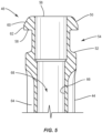
- a force is applied to gripping portion 148 to move gripping portion 148 relative to body 126 in the direction shown by arrow B in FIG. 8 and a force is applied to gripping portion 154 to move gripping portion 154 relative to body 126 in the direction shown by arrow C in FIG. 8 such that surface 150a is spaced the second distance apart from surface 156a.
- Device 112 is translated axially relative to sleeve 44 in the direction shown by arrow A in FIG. 12 such that surfaces 150a, 156a slide along surface 62.
- Device 112 may be translated axially relative to sleeve 44 in the direction shown by arrow A in FIG. 12 until shaft 114 is removed from channel 68.
- delivery system 30 includes a cement delivery system 160 having a cartridge 162 that is connected to handle 112 by a luer lock 164 and a cement delivery gun 166 that is connected to cartridge 162. Threads of luer lock 164 are mated with threads of surface 130 to connect cartridge 162 to handle 112.
- Cartridge 162 is loaded with a bone filler material, such as, for example, bone cement either before or after cartridge 162 is connected to handle 112.
- An actuator such as, for example, a trigger handle of cement delivery gun 166 is activated to move the bone filler material through lumen 124 and bores 78, 106 such that the bone filler material exits screw 86 via one or more openings in screw 86.
- a spinal construct such as, for example, a spinal rod is inserted into implant cavity 92 after driver 32 is removed from the surgical site and a setscrew is engaged with receiver 84 such that threads on an outer surface of the setscrew engage the threads on the inner surfaces of arms 88, 90.
- the setscrew is rotated relative to receiver 84 until the setscrew engages the rod to fix the rod relative to receiver 84.
- delivery system 30 includes a driver 168 that is similar to driver 32.
- Driver 168 includes an outer sleeve 170 having a lower portion 172 and an upper portion 174 that is connected with lower portion 172.
- Lower portion 172 extends along a longitudinal axis L3 between an end 176 and an opposite end 178.
- End 176 includes a circumferential cutout 180 configured for disposal of an end 182 of upper portion 174 to connect upper portion 174 with lower portion 172.
- upper portion 174 is connected with lower portion 172 to provisionally fix upper portion 174 relative to lower portion 172 such that rotation of upper portion 174 about axis L3 also rotates lower portion 172 about axis L3.
- tip 184 moves out of tool engaging portion 102 of screw 86 and the threads on surface 228 of sleeve 210 disengage the threads on the inner surfaces of arms 88, 90 of fastener 80, at which point driver 168 can be fully removed from fastener 80.
- threads of luer lock 164 are mated with threads of surface 130 to connect cartridge 162 to handle 112.
- Cartridge 162 is loaded with a bone filler material, such as, for example, bone cement either before or after cartridge 162 is connected to handle 112.
- the trigger handle of cement delivery gun 166 is activated to move the bone filler material through lumen 124, aperture 230 and bore 106 such that the bone filler material exits screw 86 via one or more openings in screw 86. As the bone filler material cures, it will bond screw 86 with bone or other tissue.
- cement delivery system 160 may be removed from device 112, and driver 168 is removed from the surgical site.
Landscapes
- Health & Medical Sciences (AREA)
- Orthopedic Medicine & Surgery (AREA)
- Life Sciences & Earth Sciences (AREA)
- Surgery (AREA)
- Neurology (AREA)
- Molecular Biology (AREA)
- General Health & Medical Sciences (AREA)
- Biomedical Technology (AREA)
- Heart & Thoracic Surgery (AREA)
- Medical Informatics (AREA)
- Nuclear Medicine, Radiotherapy & Molecular Imaging (AREA)
- Animal Behavior & Ethology (AREA)
- Engineering & Computer Science (AREA)
- Public Health (AREA)
- Veterinary Medicine (AREA)
- Dentistry (AREA)
- Oral & Maxillofacial Surgery (AREA)
- Physics & Mathematics (AREA)
- Fluid Mechanics (AREA)
- Surgical Instruments (AREA)
- Prostheses (AREA)
Claims (8)
- Abgabesystem (30) zum Behandeln von Wirbelsäulenerkrankungen, umfassend:ein erstes Instrument (32, 168), umfassend eine Außenhülse (34, 170), die sich entlang einer Längsachse (L1, L3) erstreckt, die einen Durchgang (42, 204) definiert, und eine Innenhülse (44, 210), die zu der Achse (L1, L3) koaxial ist, die ein erstes Ende (48, 212), das in dem Durchgang (42, 204) angeordnet ist, und ein zweites Ende (46, 214) aufweist, das ein erstes Gegenelement (50, 188) einschließt, wobei die Innenhülse (44) einen Kanal (68) definiert, der zu der Achse (L1) koaxial ist und sich über die gesamte Länge der Innenhülse (44) erstreckt; undein zweites Instrument (112), umfassend einen hohlen Schaft (114), der in dem Kanal (48) angeordnet ist und sich entlang einer Längsachse (L2) erstreckt, und einen Griff (116), der mit dem Schaft (114) gekoppelt ist, der Griff (116) umfassend einen Körper (126), der zu dem Schaft (114) und der Achse (L2) koaxial ist, und ein zweites Gegenelement (138, 142), das sich von dem Körper (126) erstreckt, wobei das zweite Gegenelement (138, 142) konfiguriert ist, um mit dem ersten Gegenelement (50) in Eingriff zu stehen, um das zweite Instrument (112) an dem ersten Instrument (32) derart zu befestigen, dass die Achse (L2) zu der Achse (L1, L3) koaxial ist,wobei das zweite Gegenelement (138, 142) einen ersten Flügel (138), der sich von einer ersten Seite (140) des Körpers (126) in einer freitragenden Konfiguration erstreckt, und einen zweiten Flügel (142) einschließt, der sich von einer gegenüberliegenden zweiten Seite (144) des Körpers (126) in einer freitragenden Konfiguration erstreckt;wobei der erste Flügel (138) eine erste Erstreckung (146), die sich parallel zu der Längsachse (L2) von der ersten Seite (140) erstreckt, einen ersten Griffabschnitt (148), der sich quer zu der Längsachse (L2) von der ersten Erstreckung (146) erstreckt, und eine erste Lasche (150) umfasst, die sich senkrecht zu der Längsachse (L2) von der ersten Erstreckung (146) erstreckt; undwobei der zweite Flügel (142) eine zweite Erstreckung (152), die sich parallel zu der Längsachse (L2) von der zweiten Seite (144) erstreckt, einen zweiten Griffabschnitt (154), der sich quer zu der Längsachse (L2) von der zweiten Erstreckung (152) erstreckt, und eine zweite Lasche (156) umfasst, die sich senkrecht zu der Längsachse (L2) von der zweiten Erstreckung (152) erstreckt.
- Abgabesystem (30) nach Anspruch 1, wobei ein Eingriff der Gegenelemente (50, 138, 142) verhindert, dass sich das zweite Instrument (112) relativ zu dem ersten Instrument (32, 168) proximal verschiebt.
- Abgabesystem (30) nach Anspruch 1, wobei das erste Gegenelement (50, 188) ein Flansch (50, 188) ist, der sich von einer Außenoberfläche (56, 194) der Innenhülse (44, 210) nach außen erstreckt.
- Abgabesystem (30) nach Anspruch 3, wobei die Laschen (150, 156) den Flansch (50, 188) in Eingriff nehmen, um das zweite Instrument (112) an dem ersten Instrument (32, 168) zu befestigen.
- Abgabesystem (30) nach Anspruch 4, wobei die Laschen (150, 156) einander zugewandt sind.
- Abgabesystem (30) nach Anspruch 1, wobei der Körper (126) einen zylindrischen Abschnitt (128) einschließt, der zu dem Schaft (114) koaxial ist, wobei der zylindrische Abschnitt (128) eine mit einem Gewinde versehene Außenoberfläche (130) und eine Innenoberfläche (132) aufweist, die eine Öffnung (134) definiert, die mit einem Lumen (124) des Schafts (114) in Kommunikation steht und koaxial zu diesem ist.
- Abgabesystem (30) nach Anspruch 1, wobei das erste Ende (48) einen Körper (64) und eine Spitze (70) umfasst, die mit dem Körper (64) des ersten Endes (48) abnehmbar gekoppelt ist, die Spitze (70) umfassend eine Bohrung (78), die mit dem Kanal (68) in Kommunikation steht und koaxial zu diesem ist.
- Abgabesystem (30) nach Anspruch 1, wobei das erste Ende (48) in dem Durchgang (42) drehbar angeordnet ist und eine mit einem Gewinde versehene Außenoberfläche umfasst.
Applications Claiming Priority (2)
| Application Number | Priority Date | Filing Date | Title |
|---|---|---|---|
| US16/047,590 US10932841B2 (en) | 2018-07-27 | 2018-07-27 | Spinal implant system and method |
| PCT/US2019/042309 WO2020023271A1 (en) | 2018-07-27 | 2019-07-18 | Spinal implant system and method |
Publications (3)
| Publication Number | Publication Date |
|---|---|
| EP3829467A1 EP3829467A1 (de) | 2021-06-09 |
| EP3829467A4 EP3829467A4 (de) | 2022-05-11 |
| EP3829467B1 true EP3829467B1 (de) | 2025-04-16 |
Family
ID=69179716
Family Applications (1)
| Application Number | Title | Priority Date | Filing Date |
|---|---|---|---|
| EP19840349.5A Active EP3829467B1 (de) | 2018-07-27 | 2019-07-18 | Wirbelsäulenimplantatsystem |
Country Status (6)
| Country | Link |
|---|---|
| US (2) | US10932841B2 (de) |
| EP (1) | EP3829467B1 (de) |
| JP (2) | JP2021531115A (de) |
| CN (1) | CN112533553B (de) |
| CA (1) | CA3107580A1 (de) |
| WO (1) | WO2020023271A1 (de) |
Families Citing this family (12)
| Publication number | Priority date | Publication date | Assignee | Title |
|---|---|---|---|---|
| USD963844S1 (en) * | 2018-07-27 | 2022-09-13 | Warsaw Orthopedic, Inc. | Bone filler device handle design |
| US11083501B2 (en) | 2019-04-24 | 2021-08-10 | Warsaw Orthopedic, Inc. | Surgical system and method |
| US20210113255A1 (en) | 2019-10-22 | 2021-04-22 | DePuy Synthes Products, Inc. | System and method for inserting a fastener into bone |
| US12004782B2 (en) | 2020-03-26 | 2024-06-11 | Warsaw Orthopedic, Inc. | Instrument for locking orthopedic screws |
| US11730529B2 (en) | 2020-03-26 | 2023-08-22 | Warsaw Orthopedic, Inc. | Powered modular head locker |
| EP4014904B1 (de) | 2020-12-17 | 2026-02-04 | Biedermann Technologies GmbH & Co. KG | Adaptervorrichtung und system einer adaptervorrichtung und eines knochenankers |
| US11291477B1 (en) | 2021-05-04 | 2022-04-05 | Warsaw Orthopedic, Inc. | Dorsal adjusting implant and methods of use |
| US11432848B1 (en) | 2021-05-12 | 2022-09-06 | Warsaw Orthopedic, Inc. | Top loading quick lock construct |
| US11712270B2 (en) | 2021-05-17 | 2023-08-01 | Warsaw Orthopedic, Inc. | Quick lock clamp constructs and associated methods |
| US11957391B2 (en) | 2021-11-01 | 2024-04-16 | Warsaw Orthopedic, Inc. | Bone screw having an overmold of a shank |
| US12440255B2 (en) | 2021-11-08 | 2025-10-14 | Medos International Sárl | Bone screw inserters and methods |
| WO2026009303A1 (ja) * | 2024-07-02 | 2026-01-08 | 株式会社スパインクロニクルジャパン | 治療器具 |
Family Cites Families (20)
| Publication number | Priority date | Publication date | Assignee | Title |
|---|---|---|---|---|
| US2625967A (en) * | 1949-12-19 | 1953-01-20 | Illinois Tool Works | Screw-holding and screw-driving tool |
| US3312127A (en) * | 1965-02-16 | 1967-04-04 | Semco Twist Drill And Tool Co | Twist drill |
| US3693381A (en) * | 1971-02-12 | 1972-09-26 | Hill Rockford Co | Torque responsive clutch |
| US4919153A (en) * | 1988-10-11 | 1990-04-24 | Origin Medsystems, Inc. | Method and apparatus for removing pre-placed prosthetic joints and preparing for their replacement |
| EP1605846A4 (de) * | 2003-02-28 | 2008-02-06 | Triage Medical Inc | Werkzeug für distale knochenanker mit sekundärer kompression |
| US20080154277A1 (en) * | 2004-10-26 | 2008-06-26 | Scott Machalk | Tool apparatus for locking a spinal rod in an anchoring device therefor |
| US20070016219A1 (en) * | 2005-07-14 | 2007-01-18 | Levine Marc J | Vertebral Marker Devices and Installation Methods |
| US9220546B2 (en) * | 2008-01-11 | 2015-12-29 | Trimed, Inc. | Expansion and compression instrument for fracture fixation |
| US8236006B2 (en) * | 2008-01-17 | 2012-08-07 | Life Spine, Inc. | One step entry pedicular preparation device and disc access system |
| US20090275954A1 (en) * | 2008-04-30 | 2009-11-05 | Phan Christopher U | Apparatus and methods for inserting facet screws |
| US8246627B2 (en) * | 2008-08-07 | 2012-08-21 | Stryker Corporation | Cement delivery device for introducing cement into tissue, the device having a cavity creator |
| WO2010051386A1 (en) * | 2008-10-30 | 2010-05-06 | Depuy Spine, Inc. | Systems and methods for delivering bone cement to a bone anchor |
| EP2572663B1 (de) * | 2009-07-01 | 2015-09-09 | Biedermann Technologies GmbH & Co. KG | Instrumente zur Verwendung mit einem Knochenanker mit Stopfelement |
| US8747411B2 (en) * | 2009-09-30 | 2014-06-10 | Michael David Mitchell | Fluid delivery and bone screw driver apparatus |
| US20120059385A1 (en) * | 2010-07-07 | 2012-03-08 | Orthohelix Surgical Designs, Inc. | Variable angle depth limited fastener driver and variable angle fixation system for use in orthopedic plates |
| US9724149B2 (en) * | 2013-03-07 | 2017-08-08 | Warsaw Orhtopedic, Inc. | Surgical implant system and method |
| US9433445B2 (en) * | 2013-03-14 | 2016-09-06 | DePuy Synthes Products, Inc. | Bone anchors and surgical instruments with integrated guide tips |
| US9855087B2 (en) * | 2014-08-04 | 2018-01-02 | DePuy Synthes Products, LLC | Methods and devices for spinal screw insertion |
| US10080583B2 (en) * | 2014-12-12 | 2018-09-25 | Depuy Mitel, Llc | Dilator for accessing a joint space |
| DE102017101348A1 (de) * | 2017-01-25 | 2018-07-26 | Aesculap Ag | Achsgenauer Schraubendreher |
-
2018
- 2018-07-27 US US16/047,590 patent/US10932841B2/en active Active
-
2019
- 2019-07-18 WO PCT/US2019/042309 patent/WO2020023271A1/en not_active Ceased
- 2019-07-18 EP EP19840349.5A patent/EP3829467B1/de active Active
- 2019-07-18 JP JP2021502994A patent/JP2021531115A/ja active Pending
- 2019-07-18 CA CA3107580A patent/CA3107580A1/en not_active Abandoned
- 2019-07-18 CN CN201980048910.8A patent/CN112533553B/zh active Active
-
2021
- 2021-02-01 US US17/164,379 patent/US11826086B2/en active Active
-
2024
- 2024-01-24 JP JP2024008554A patent/JP7770435B2/ja active Active
Also Published As
| Publication number | Publication date |
|---|---|
| JP2021531115A (ja) | 2021-11-18 |
| JP7770435B2 (ja) | 2025-11-14 |
| US20200030015A1 (en) | 2020-01-30 |
| CN112533553A (zh) | 2021-03-19 |
| EP3829467A1 (de) | 2021-06-09 |
| EP3829467A4 (de) | 2022-05-11 |
| CA3107580A1 (en) | 2020-01-30 |
| JP2024038471A (ja) | 2024-03-19 |
| CN112533553B (zh) | 2024-02-27 |
| US20210177480A1 (en) | 2021-06-17 |
| WO2020023271A1 (en) | 2020-01-30 |
| US11826086B2 (en) | 2023-11-28 |
| US10932841B2 (en) | 2021-03-02 |
Similar Documents
| Publication | Publication Date | Title |
|---|---|---|
| EP3829467B1 (de) | Wirbelsäulenimplantatsystem | |
| EP3525700B1 (de) | Wirbelsäulenimplantatsystem | |
| US20200323644A1 (en) | Spinal implant system and method | |
| US9572605B2 (en) | Surgical instrument and method | |
| EP2884923B1 (de) | Wirbelsäulenimplantatsystem | |
| EP3755251B1 (de) | Chirurgisches instrument | |
| US20160089188A1 (en) | Spinal implant system and method | |
| US20210106364A1 (en) | Spinal implant system and method | |
| US12035950B2 (en) | Surgical system and method | |
| EP3876850B1 (de) | Wirbelsäulenimplantatsystem | |
| EP3958757B1 (de) | Chirurgisches system | |
| US10441324B2 (en) | Spinal construct and method | |
| US11559338B1 (en) | Spinal implant system and method | |
| US11547454B1 (en) | Spinal implant system and method | |
| US11490934B1 (en) | Spinal implant system and method | |
| US11679003B2 (en) | Surgical implant system and method | |
| EP3836858B1 (de) | Wirbelsäulenimplantatsystem | |
| US12171468B2 (en) | Spinal implant system and method | |
| EP3965673B1 (de) | Wirbelsäulenimplantatsystem | |
| US9848928B2 (en) | Spinal implant system and methods of use |
Legal Events
| Date | Code | Title | Description |
|---|---|---|---|
| STAA | Information on the status of an ep patent application or granted ep patent |
Free format text: STATUS: THE INTERNATIONAL PUBLICATION HAS BEEN MADE |
|
| PUAI | Public reference made under article 153(3) epc to a published international application that has entered the european phase |
Free format text: ORIGINAL CODE: 0009012 |
|
| STAA | Information on the status of an ep patent application or granted ep patent |
Free format text: STATUS: REQUEST FOR EXAMINATION WAS MADE |
|
| 17P | Request for examination filed |
Effective date: 20210225 |
|
| AK | Designated contracting states |
Kind code of ref document: A1 Designated state(s): AL AT BE BG CH CY CZ DE DK EE ES FI FR GB GR HR HU IE IS IT LI LT LU LV MC MK MT NL NO PL PT RO RS SE SI SK SM TR |
|
| DAV | Request for validation of the european patent (deleted) | ||
| DAX | Request for extension of the european patent (deleted) | ||
| A4 | Supplementary search report drawn up and despatched |
Effective date: 20220411 |
|
| RIC1 | Information provided on ipc code assigned before grant |
Ipc: A61B 17/34 20060101ALI20220405BHEP Ipc: A61B 17/88 20060101ALI20220405BHEP Ipc: A61B 17/86 20060101ALI20220405BHEP Ipc: A61B 17/70 20060101AFI20220405BHEP |
|
| GRAP | Despatch of communication of intention to grant a patent |
Free format text: ORIGINAL CODE: EPIDOSNIGR1 |
|
| STAA | Information on the status of an ep patent application or granted ep patent |
Free format text: STATUS: GRANT OF PATENT IS INTENDED |
|
| INTG | Intention to grant announced |
Effective date: 20241107 |
|
| GRAS | Grant fee paid |
Free format text: ORIGINAL CODE: EPIDOSNIGR3 |
|
| GRAA | (expected) grant |
Free format text: ORIGINAL CODE: 0009210 |
|
| STAA | Information on the status of an ep patent application or granted ep patent |
Free format text: STATUS: THE PATENT HAS BEEN GRANTED |
|
| AK | Designated contracting states |
Kind code of ref document: B1 Designated state(s): AL AT BE BG CH CY CZ DE DK EE ES FI FR GB GR HR HU IE IS IT LI LT LU LV MC MK MT NL NO PL PT RO RS SE SI SK SM TR |
|
| REG | Reference to a national code |
Ref country code: GB Ref legal event code: FG4D |
|
| REG | Reference to a national code |
Ref country code: CH Ref legal event code: EP |
|
| REG | Reference to a national code |
Ref country code: IE Ref legal event code: FG4D |
|
| REG | Reference to a national code |
Ref country code: DE Ref legal event code: R096 Ref document number: 602019068792 Country of ref document: DE |
|
| PGFP | Annual fee paid to national office [announced via postgrant information from national office to epo] |
Ref country code: FR Payment date: 20250620 Year of fee payment: 7 |
|
| REG | Reference to a national code |
Ref country code: NL Ref legal event code: MP Effective date: 20250416 |
|
| PG25 | Lapsed in a contracting state [announced via postgrant information from national office to epo] |
Ref country code: NL Free format text: LAPSE BECAUSE OF FAILURE TO SUBMIT A TRANSLATION OF THE DESCRIPTION OR TO PAY THE FEE WITHIN THE PRESCRIBED TIME-LIMIT Effective date: 20250416 |
|
| REG | Reference to a national code |
Ref country code: AT Ref legal event code: MK05 Ref document number: 1785005 Country of ref document: AT Kind code of ref document: T Effective date: 20250416 |
|
| PG25 | Lapsed in a contracting state [announced via postgrant information from national office to epo] |
Ref country code: PT Free format text: LAPSE BECAUSE OF FAILURE TO SUBMIT A TRANSLATION OF THE DESCRIPTION OR TO PAY THE FEE WITHIN THE PRESCRIBED TIME-LIMIT Effective date: 20250818 Ref country code: ES Free format text: LAPSE BECAUSE OF FAILURE TO SUBMIT A TRANSLATION OF THE DESCRIPTION OR TO PAY THE FEE WITHIN THE PRESCRIBED TIME-LIMIT Effective date: 20250416 Ref country code: FI Free format text: LAPSE BECAUSE OF FAILURE TO SUBMIT A TRANSLATION OF THE DESCRIPTION OR TO PAY THE FEE WITHIN THE PRESCRIBED TIME-LIMIT Effective date: 20250416 |
|
| PGFP | Annual fee paid to national office [announced via postgrant information from national office to epo] |
Ref country code: DE Payment date: 20250620 Year of fee payment: 7 |
|
| REG | Reference to a national code |
Ref country code: LT Ref legal event code: MG9D |
|
| PG25 | Lapsed in a contracting state [announced via postgrant information from national office to epo] |
Ref country code: GR Free format text: LAPSE BECAUSE OF FAILURE TO SUBMIT A TRANSLATION OF THE DESCRIPTION OR TO PAY THE FEE WITHIN THE PRESCRIBED TIME-LIMIT Effective date: 20250717 Ref country code: NO Free format text: LAPSE BECAUSE OF FAILURE TO SUBMIT A TRANSLATION OF THE DESCRIPTION OR TO PAY THE FEE WITHIN THE PRESCRIBED TIME-LIMIT Effective date: 20250716 |
|
| PG25 | Lapsed in a contracting state [announced via postgrant information from national office to epo] |
Ref country code: PL Free format text: LAPSE BECAUSE OF FAILURE TO SUBMIT A TRANSLATION OF THE DESCRIPTION OR TO PAY THE FEE WITHIN THE PRESCRIBED TIME-LIMIT Effective date: 20250416 |
|
| PG25 | Lapsed in a contracting state [announced via postgrant information from national office to epo] |
Ref country code: BG Free format text: LAPSE BECAUSE OF FAILURE TO SUBMIT A TRANSLATION OF THE DESCRIPTION OR TO PAY THE FEE WITHIN THE PRESCRIBED TIME-LIMIT Effective date: 20250416 |
|
| PG25 | Lapsed in a contracting state [announced via postgrant information from national office to epo] |
Ref country code: HR Free format text: LAPSE BECAUSE OF FAILURE TO SUBMIT A TRANSLATION OF THE DESCRIPTION OR TO PAY THE FEE WITHIN THE PRESCRIBED TIME-LIMIT Effective date: 20250416 |
|
| PG25 | Lapsed in a contracting state [announced via postgrant information from national office to epo] |
Ref country code: AT Free format text: LAPSE BECAUSE OF FAILURE TO SUBMIT A TRANSLATION OF THE DESCRIPTION OR TO PAY THE FEE WITHIN THE PRESCRIBED TIME-LIMIT Effective date: 20250416 |
|
| PG25 | Lapsed in a contracting state [announced via postgrant information from national office to epo] |
Ref country code: RS Free format text: LAPSE BECAUSE OF FAILURE TO SUBMIT A TRANSLATION OF THE DESCRIPTION OR TO PAY THE FEE WITHIN THE PRESCRIBED TIME-LIMIT Effective date: 20250716 |
|
| PG25 | Lapsed in a contracting state [announced via postgrant information from national office to epo] |
Ref country code: IS Free format text: LAPSE BECAUSE OF FAILURE TO SUBMIT A TRANSLATION OF THE DESCRIPTION OR TO PAY THE FEE WITHIN THE PRESCRIBED TIME-LIMIT Effective date: 20250816 |
|
| PG25 | Lapsed in a contracting state [announced via postgrant information from national office to epo] |
Ref country code: LV Free format text: LAPSE BECAUSE OF FAILURE TO SUBMIT A TRANSLATION OF THE DESCRIPTION OR TO PAY THE FEE WITHIN THE PRESCRIBED TIME-LIMIT Effective date: 20250416 |
|
| PG25 | Lapsed in a contracting state [announced via postgrant information from national office to epo] |
Ref country code: SM Free format text: LAPSE BECAUSE OF FAILURE TO SUBMIT A TRANSLATION OF THE DESCRIPTION OR TO PAY THE FEE WITHIN THE PRESCRIBED TIME-LIMIT Effective date: 20250416 Ref country code: DK Free format text: LAPSE BECAUSE OF FAILURE TO SUBMIT A TRANSLATION OF THE DESCRIPTION OR TO PAY THE FEE WITHIN THE PRESCRIBED TIME-LIMIT Effective date: 20250416 |
|
| PG25 | Lapsed in a contracting state [announced via postgrant information from national office to epo] |
Ref country code: CZ Free format text: LAPSE BECAUSE OF FAILURE TO SUBMIT A TRANSLATION OF THE DESCRIPTION OR TO PAY THE FEE WITHIN THE PRESCRIBED TIME-LIMIT Effective date: 20250416 |
|
| PG25 | Lapsed in a contracting state [announced via postgrant information from national office to epo] |
Ref country code: EE Free format text: LAPSE BECAUSE OF FAILURE TO SUBMIT A TRANSLATION OF THE DESCRIPTION OR TO PAY THE FEE WITHIN THE PRESCRIBED TIME-LIMIT Effective date: 20250416 |
|
| PG25 | Lapsed in a contracting state [announced via postgrant information from national office to epo] |
Ref country code: RO Free format text: LAPSE BECAUSE OF FAILURE TO SUBMIT A TRANSLATION OF THE DESCRIPTION OR TO PAY THE FEE WITHIN THE PRESCRIBED TIME-LIMIT Effective date: 20250416 Ref country code: SK Free format text: LAPSE BECAUSE OF FAILURE TO SUBMIT A TRANSLATION OF THE DESCRIPTION OR TO PAY THE FEE WITHIN THE PRESCRIBED TIME-LIMIT Effective date: 20250416 |
|
| PG25 | Lapsed in a contracting state [announced via postgrant information from national office to epo] |
Ref country code: IT Free format text: LAPSE BECAUSE OF FAILURE TO SUBMIT A TRANSLATION OF THE DESCRIPTION OR TO PAY THE FEE WITHIN THE PRESCRIBED TIME-LIMIT Effective date: 20250416 |