EP3829176B1 - Method of constructing merge list - Google Patents
Method of constructing merge list Download PDFInfo
- Publication number
- EP3829176B1 EP3829176B1 EP20216558.5A EP20216558A EP3829176B1 EP 3829176 B1 EP3829176 B1 EP 3829176B1 EP 20216558 A EP20216558 A EP 20216558A EP 3829176 B1 EP3829176 B1 EP 3829176B1
- Authority
- EP
- European Patent Office
- Prior art keywords
- block
- merge candidate
- quantization parameter
- spatial
- unit
- Prior art date
- Legal status (The legal status is an assumption and is not a legal conclusion. Google has not performed a legal analysis and makes no representation as to the accuracy of the status listed.)
- Active
Links
- 238000000034 method Methods 0.000 title claims description 29
- 238000013139 quantization Methods 0.000 claims description 136
- 230000002123 temporal effect Effects 0.000 claims description 48
- 239000013598 vector Substances 0.000 claims description 26
- 238000000638 solvent extraction Methods 0.000 claims description 22
- 208000037170 Delayed Emergence from Anesthesia Diseases 0.000 claims description 20
- 238000012935 Averaging Methods 0.000 claims 1
- 238000010586 diagram Methods 0.000 description 16
- 238000012805 post-processing Methods 0.000 description 7
- 239000011159 matrix material Substances 0.000 description 6
- 238000005192 partition Methods 0.000 description 4
- 238000013459 approach Methods 0.000 description 2
- 238000004891 communication Methods 0.000 description 2
- 238000012360 testing method Methods 0.000 description 2
- 230000000903 blocking effect Effects 0.000 description 1
- 230000001419 dependent effect Effects 0.000 description 1
- 238000009795 derivation Methods 0.000 description 1
- 230000000694 effects Effects 0.000 description 1
- 239000000284 extract Substances 0.000 description 1
- 238000001914 filtration Methods 0.000 description 1
- 238000012986 modification Methods 0.000 description 1
- 230000004048 modification Effects 0.000 description 1
Images


Classifications
-
- H—ELECTRICITY
- H04—ELECTRIC COMMUNICATION TECHNIQUE
- H04N—PICTORIAL COMMUNICATION, e.g. TELEVISION
- H04N19/00—Methods or arrangements for coding, decoding, compressing or decompressing digital video signals
- H04N19/10—Methods or arrangements for coding, decoding, compressing or decompressing digital video signals using adaptive coding
- H04N19/102—Methods or arrangements for coding, decoding, compressing or decompressing digital video signals using adaptive coding characterised by the element, parameter or selection affected or controlled by the adaptive coding
- H04N19/124—Quantisation
- H04N19/126—Details of normalisation or weighting functions, e.g. normalisation matrices or variable uniform quantisers
-
- H—ELECTRICITY
- H04—ELECTRIC COMMUNICATION TECHNIQUE
- H04N—PICTORIAL COMMUNICATION, e.g. TELEVISION
- H04N19/00—Methods or arrangements for coding, decoding, compressing or decompressing digital video signals
- H04N19/10—Methods or arrangements for coding, decoding, compressing or decompressing digital video signals using adaptive coding
- H04N19/134—Methods or arrangements for coding, decoding, compressing or decompressing digital video signals using adaptive coding characterised by the element, parameter or criterion affecting or controlling the adaptive coding
- H04N19/136—Incoming video signal characteristics or properties
- H04N19/137—Motion inside a coding unit, e.g. average field, frame or block difference
- H04N19/139—Analysis of motion vectors, e.g. their magnitude, direction, variance or reliability
-
- H—ELECTRICITY
- H04—ELECTRIC COMMUNICATION TECHNIQUE
- H04N—PICTORIAL COMMUNICATION, e.g. TELEVISION
- H04N19/00—Methods or arrangements for coding, decoding, compressing or decompressing digital video signals
- H04N19/10—Methods or arrangements for coding, decoding, compressing or decompressing digital video signals using adaptive coding
- H04N19/102—Methods or arrangements for coding, decoding, compressing or decompressing digital video signals using adaptive coding characterised by the element, parameter or selection affected or controlled by the adaptive coding
- H04N19/103—Selection of coding mode or of prediction mode
- H04N19/105—Selection of the reference unit for prediction within a chosen coding or prediction mode, e.g. adaptive choice of position and number of pixels used for prediction
-
- H—ELECTRICITY
- H04—ELECTRIC COMMUNICATION TECHNIQUE
- H04N—PICTORIAL COMMUNICATION, e.g. TELEVISION
- H04N19/00—Methods or arrangements for coding, decoding, compressing or decompressing digital video signals
- H04N19/10—Methods or arrangements for coding, decoding, compressing or decompressing digital video signals using adaptive coding
- H04N19/102—Methods or arrangements for coding, decoding, compressing or decompressing digital video signals using adaptive coding characterised by the element, parameter or selection affected or controlled by the adaptive coding
- H04N19/103—Selection of coding mode or of prediction mode
- H04N19/109—Selection of coding mode or of prediction mode among a plurality of temporal predictive coding modes
-
- H—ELECTRICITY
- H04—ELECTRIC COMMUNICATION TECHNIQUE
- H04N—PICTORIAL COMMUNICATION, e.g. TELEVISION
- H04N19/00—Methods or arrangements for coding, decoding, compressing or decompressing digital video signals
- H04N19/10—Methods or arrangements for coding, decoding, compressing or decompressing digital video signals using adaptive coding
- H04N19/102—Methods or arrangements for coding, decoding, compressing or decompressing digital video signals using adaptive coding characterised by the element, parameter or selection affected or controlled by the adaptive coding
- H04N19/124—Quantisation
-
- H—ELECTRICITY
- H04—ELECTRIC COMMUNICATION TECHNIQUE
- H04N—PICTORIAL COMMUNICATION, e.g. TELEVISION
- H04N19/00—Methods or arrangements for coding, decoding, compressing or decompressing digital video signals
- H04N19/10—Methods or arrangements for coding, decoding, compressing or decompressing digital video signals using adaptive coding
- H04N19/169—Methods or arrangements for coding, decoding, compressing or decompressing digital video signals using adaptive coding characterised by the coding unit, i.e. the structural portion or semantic portion of the video signal being the object or the subject of the adaptive coding
- H04N19/17—Methods or arrangements for coding, decoding, compressing or decompressing digital video signals using adaptive coding characterised by the coding unit, i.e. the structural portion or semantic portion of the video signal being the object or the subject of the adaptive coding the unit being an image region, e.g. an object
- H04N19/174—Methods or arrangements for coding, decoding, compressing or decompressing digital video signals using adaptive coding characterised by the coding unit, i.e. the structural portion or semantic portion of the video signal being the object or the subject of the adaptive coding the unit being an image region, e.g. an object the region being a slice, e.g. a line of blocks or a group of blocks
-
- H—ELECTRICITY
- H04—ELECTRIC COMMUNICATION TECHNIQUE
- H04N—PICTORIAL COMMUNICATION, e.g. TELEVISION
- H04N19/00—Methods or arrangements for coding, decoding, compressing or decompressing digital video signals
- H04N19/10—Methods or arrangements for coding, decoding, compressing or decompressing digital video signals using adaptive coding
- H04N19/169—Methods or arrangements for coding, decoding, compressing or decompressing digital video signals using adaptive coding characterised by the coding unit, i.e. the structural portion or semantic portion of the video signal being the object or the subject of the adaptive coding
- H04N19/17—Methods or arrangements for coding, decoding, compressing or decompressing digital video signals using adaptive coding characterised by the coding unit, i.e. the structural portion or semantic portion of the video signal being the object or the subject of the adaptive coding the unit being an image region, e.g. an object
- H04N19/176—Methods or arrangements for coding, decoding, compressing or decompressing digital video signals using adaptive coding characterised by the coding unit, i.e. the structural portion or semantic portion of the video signal being the object or the subject of the adaptive coding the unit being an image region, e.g. an object the region being a block, e.g. a macroblock
-
- H—ELECTRICITY
- H04—ELECTRIC COMMUNICATION TECHNIQUE
- H04N—PICTORIAL COMMUNICATION, e.g. TELEVISION
- H04N19/00—Methods or arrangements for coding, decoding, compressing or decompressing digital video signals
- H04N19/10—Methods or arrangements for coding, decoding, compressing or decompressing digital video signals using adaptive coding
- H04N19/189—Methods or arrangements for coding, decoding, compressing or decompressing digital video signals using adaptive coding characterised by the adaptation method, adaptation tool or adaptation type used for the adaptive coding
- H04N19/196—Methods or arrangements for coding, decoding, compressing or decompressing digital video signals using adaptive coding characterised by the adaptation method, adaptation tool or adaptation type used for the adaptive coding being specially adapted for the computation of encoding parameters, e.g. by averaging previously computed encoding parameters
- H04N19/198—Methods or arrangements for coding, decoding, compressing or decompressing digital video signals using adaptive coding characterised by the adaptation method, adaptation tool or adaptation type used for the adaptive coding being specially adapted for the computation of encoding parameters, e.g. by averaging previously computed encoding parameters including smoothing of a sequence of encoding parameters, e.g. by averaging, by choice of the maximum, minimum or median value
-
- H—ELECTRICITY
- H04—ELECTRIC COMMUNICATION TECHNIQUE
- H04N—PICTORIAL COMMUNICATION, e.g. TELEVISION
- H04N19/00—Methods or arrangements for coding, decoding, compressing or decompressing digital video signals
- H04N19/46—Embedding additional information in the video signal during the compression process
- H04N19/463—Embedding additional information in the video signal during the compression process by compressing encoding parameters before transmission
-
- H—ELECTRICITY
- H04—ELECTRIC COMMUNICATION TECHNIQUE
- H04N—PICTORIAL COMMUNICATION, e.g. TELEVISION
- H04N19/00—Methods or arrangements for coding, decoding, compressing or decompressing digital video signals
- H04N19/50—Methods or arrangements for coding, decoding, compressing or decompressing digital video signals using predictive coding
- H04N19/503—Methods or arrangements for coding, decoding, compressing or decompressing digital video signals using predictive coding involving temporal prediction
- H04N19/51—Motion estimation or motion compensation
- H04N19/513—Processing of motion vectors
- H04N19/517—Processing of motion vectors by encoding
- H04N19/52—Processing of motion vectors by encoding by predictive encoding
-
- H—ELECTRICITY
- H04—ELECTRIC COMMUNICATION TECHNIQUE
- H04N—PICTORIAL COMMUNICATION, e.g. TELEVISION
- H04N19/00—Methods or arrangements for coding, decoding, compressing or decompressing digital video signals
- H04N19/50—Methods or arrangements for coding, decoding, compressing or decompressing digital video signals using predictive coding
- H04N19/593—Methods or arrangements for coding, decoding, compressing or decompressing digital video signals using predictive coding involving spatial prediction techniques
Definitions
- the present invention relates to a method of constructing merge list, and more particularly, to a method of deriving spatial merge candidates based on a size and a partition index of a prediction unit and deriving a temporal merge candidate.
- Methods for compressing video data include MPEG-2, MPEG-4 and H.264/MPEG-4 AVC. According to these methods, one picture is divided into macroblocks to encode an image, the respective macroblocks are encoded by generating a prediction block using inter prediction or intra prediction. The difference between an original block and the prediction block is transformed to generate a transformed block, and the transformed block is quantized using a quantization parameter and one of a plurality of predetermined quantization matrices. The quantized coefficient of the quantized block are scanned by a predetermined scan type and then entropy-coded. The quantization parameteris adjusted per macroblock and encoded using a previous quantization parameter.
- motion estimation is used to eliminate temporal redundancy between consecutive pictures.
- one or more reference pictures are used to estimate motion of a current block, and motion compensation is performed to generate a prediction block using motion information.
- the motion information includes one or more reference picture indexes and one or more motion vectors.
- the motion vector of the motion information is predictively encoded using neighboring motion vectors, and the reference picture indexes are encoded without neighboring reference picture indexes.
- the present invention is directed to a method of deriving spatial merge candidates based on a size and a partition index of a prediction unit and deriving a temporal merge candidate to construct merge list.
- I-K KIM ET AL "CE2: Test result of asymmetric motion partition (AMP)", 6. JCT-VC MEETING; 97. MPEG MEETING; 14-7-2011 - 22-7-2011; TORINO; (JOINT COLLABORATIVE TEAM ON VIDEO CODING OF ISO/ IEC JTC1/SC29/WG11 AND ITU-T SG.16); URL: HTTP://WFTP3.ITU.INT/ AV-ARCH/JCTVC-SITE/ discloses test results of asymmetric motion partition (AMP). With encoding speedup, the average gain is 0.6% with 12% encoding and 1% decoding time decrease.
- One aspect of the present invention provides amethod of constructing a merge candidate list, comprising:checking availability of spatial merge candidates, checking availability of a temporal merge candidate, constructing the merge candidate list using available spatial and temporal merge candidates, and adding one or more candidates if the number of available spatial and temporal merge candidates is smaller than a predetermined number.
- the spatial merge candidate is motion information of a spatial merge candidate block
- the spatial merge candidate block is a left block, an above block, an above-right block, a left-below block or an above-left block of the current block
- the spatial merge candidate corresponding to a first prediction unit partitioned by the asymmetric partitioning is set as unavailable.
- a method checks availability of spatial and temporal merge candidates and constructs the merge candidate list using available spatial and temporal merge candidates, and adds one or more candidates if the number of available spatial and temporal merge candidates is smaller than a predetermined number.
- the spatial merge candidate is motion information of a spatial merge candidate block
- the spatial merge candidate block is a left block, an above block, an above-right block, a left-below block or an above-left block of the current block
- the spatial merge candidate corresponding to a first prediction unit partitioned by the asymmetric partitioning is set as unavailable.
- the coding efficiency of residual block is improved by adaptively adjusting a quantization parameter per a quantization unit and generating a quantization parameter predictor using multiple neighboring quantization parameters.
- An image encoding apparatus and an image decoding apparatus may be a user terminal such as a personal computer, a personal mobile terminal, a mobile multimedia player, a smartphone or a wireless communication terminal.
- the image encoding device and the image decoding device may be include a communication unit for communicating with various devices, a memory for storing various programs and data used to encode or decode images.
- FIG. 1 is a block diagram of an image coding apparatus 100 according to the present invention.
- the image coding apparatus 100 includes a picture division unit 110, an intra prediction unit 120, an inter prediction unit 130, a transform unit 140, a quantization unit 150, a scanning unit 160, an entropy coding unit 170, an inverse quantization/transform unit 180, a post-processing unit 190 and a picture storing unit 195.
- the picture division unit 110 divides a picture or a slice into a plurality of largest coding units (LCUs), and divides each LCU into one or more coding units.
- the size of LCU may be 32x32, 64x64 or 128x128.
- the picture division unit 110 determines prediction mode and partitioning mode of each coding unit.
- An LCU includes one or more coding units.
- the LCU has a recursive quad tree structure to specify a division structure of the LCU. Parameters for specifying the maximum size and the minimum size of the coding unit are included in a sequence parameter set.
- the division structure is specified by one or more split coding unit flags (split_cu_flags).
- split_cu_flags The size of acoding unit is 2Nx2N. If the size of the LCU is 64x64 and the size of a smallest coding unit (SCU) is 8x8, the size of the coding unit may be 64x64, 32x32, 16x16 or 8x8.
- a coding unit includes one or more prediction units.
- the size of the prediction unit is 2Nx2N or NxN.
- the size of the prediction unit is specified by the partitioning mode.
- the partitioning mode is one of 2Nx2N,2NxN, Nx2N andNxN if the coding unit is partitioned symmetrically.
- the partitioning mode is one of 2NxnU, 2NxnD, nLx2N and nRx2N if the coding unit is partitionedasymmetrically.
- the partitioning modes are allowed based on the size of the coding unit to reduce complexity of hardware. If the coding unit has a minimum size, the asymmetric partitioning may not be allowed. Also, if the coding unit has the minimum size, NxN partitioning mode may not be allowed.
- a coding unit includes one or more transform units.
- the transform unit has a recursive quad tree structure to specify a division structure of the coding unit.
- the division structure is specified by one or more split transform unit flags (split_tu_flags).
- split_tu_flags Parameters for specifying the maximum size and the minimum size of the lumatransform unit are included in a sequence parameter set.
- the intra prediction unit 120 determines an intra prediction mode of a current prediction unit and generates a prediction block using the intra prediction mode.
- the inter prediction unit 130 determines motion information of a current prediction unit using one or more reference pictures stored in the picture storing unit 195, and generates a prediction block of the prediction unit.
- the motion information includes one or more reference picture indexes and one or more motion vectors.
- the transform unit 140 transforms a residual block to generate a transformed block.
- the residual block has the same size of the transform unit. If the prediction unit is larger than the transform unit, the residual signals between the current block and the prediction block are partitioned into multiple residual blocks.
- the quantization unit 150 determines a quantization parameter for quantizing the transformed block.
- the quantization parameter is a quantization step size.
- the quantization parameter is determined per quantization unit.
- the size of the quantization unit may vary and be one of allowable sizes of coding unit. If a size of the coding unit is equal to or larger than theminimum size of thequantization unit, the coding unit becomes the quantization unit.
- a plurality of coding units may be included in a quantization unit of minimum size.
- Theminimum size of the quantization unit is determined per picture and a parameter for specifying the minimum size of thequantization unit is included in a picture parameter set.
- the quantization unit 150 generates a quantization parameter predictor and generates a differential quantization parameter by subtracting the quantization parameter predictor from the quantizationparameter.
- the differential quantization parameter is entropy-coded.
- the quantization parameter predictor is generated by using quantization parameters of neighboring coding units and a quantization parameter of previous coding unit as follows.
- a left quantization parameter, an above quantization parameter and a previous quantization parameter are sequentially retrieved in this order.
- An average of the first two available quantization parameters retrieved in that order is set as the quantization parameter predictor when two or more quantization parameters are available, and when only one quantization parameter is available, the available quantization parameter is set as the quantization parameter predictor. That is, if the left and above quantization parameters are available, an average of the left and above quantization parameters is set as the quantization parameter predictor. If only one of the left and above quantization parameters is available, an average of the available quantization parameter and the previous quantization parameters is set as the quantization parameter predictor. If both of the left and above quantization parameters are unavailable, the previous quantization parameter is set as the quantization parameter predictor. The average is rounded off.
- the differential quantization parameter is converted into bins for the absolute value of the differential quantization parameter and a bin for indicating sign of the differential quantization parameter through a binarization process, and the bins are arithmetically coded. If the absolute value of the differential quantization parameter is 0, the bin for indicating sign may be omitted. Truncated unary is used for binarization of the absolute.
- the quantization unit 150 quantizes the transformed block using a quantization matrix and the quantization parameter to generate a quantized block.
- the quantized block is provided to the inverse quantization/transform unit 180 and the scanning unit 160.
- the scanning unit 160 determines applies a scan pattern to the quantized block.
- a diagonal scan is used as the scan pattern if CABAC is used for entropy coding.
- the quantized coefficients of the quantized block are split into coefficient components.
- the coefficient components are significant flags, coefficient signs and coefficient levels.
- the diagonal scan is applied to each of the coefficient components.
- the significant coefficient indicates whether the corresponding quantized coefficient is zero or not.
- the coefficient sign indicates a sign of non-zero quantized coefficient, and the coefficient level indicates an absolute value of non-zero quantized coefficient.
- the quantized block is divided into multiple subsetsand the diagonal scan is applied to each subset. Significant flags, coefficient signs and coefficients levels of each subset are scanned respectively according to the diagonal scan.
- Thepredetermined size is 4x4.
- the subset is a 4x4 block containing 16 transform coefficients.
- the scan pattern for scanning the subsets is the same as the scan pattern for scanning the coefficient components.
- the significant flags, the coefficient signs and the coefficients levels of each subset are scannedin the reverse direction.
- the subsets are also scanned in the reverse direction.
- a parameter indicating last non-zero coefficient position is encoded and transmitted to a decoding side.
- the parameter indicating last non-zero coefficient position specifies a position of last non-zero quantized coefficient within the quantized block.
- a non-zero subset flag is defined for each subset other than the first subset and the last subset and is transmitted to the decoding side.
- the first subset covers a DC coefficient.
- the last subset covers the last non-zero coefficient.
- the non-zero subset flag indicates whether the subset contains non-zero coefficients or not.
- the entropy coding unit 170 entropy-codes the scanned componentby the scanning unit 160, intra prediction information received from the intra prediction unit 120, motion information received from the inter prediction unit 130, and so on.
- the inverse quantization/transform unit 180 inversely quantizes the quantized coefficients of the quantized block, and inversely transforms the inverse quantized block to generate residual block.
- the post-processing unit 190 performs a deblocking filtering process for removing blocking artifact generated in a reconstructed picture.
- the picture storing unit 195 receives post-processed image from the post-processing unit 190, and stores the image in picture units.
- a picture may be a frame or a field.
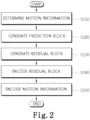
- FIG. 2 is a flow chart illustrating a method of encoding video datain an inter prediction mode according to the present invention.
- Motion information of a current block is determined (S110).
- the current block is a prediction unit.
- a size of the current block is determined by a size and a partitioning mode of the coding unit.
- the motion information varies according to a prediction type. If the prediction type is a uni-directional prediction, the motion information includes a reference index specifying a picture of a reference list 0, and a motion vector. If the prediction type is a bi-directional prediction, the motion information includes two reference indexes specifying a picture of a reference list 0 and a picture of a reference list 1, and a list 0 motion vector and a list 1 motion vector.
- Aprediction block of the current block is generated using the motion information (S120). If the motion vector indicates a pixel position, the prediction block is generated by copying a block of the reference picture specified by the motion vector. If the motion vector indicates a sub-pixel position, the prediction block is generated by interpolating the pixels of the reference picture.
- a residual block is generated using the current block and the prediction block (S130).
- the residual block has the same size of the transform unit. If the prediction unit is larger than the transform unit, the residual signals between the current block and the prediction block are into multiple residual blocks.
- the residual block is encoded (S140).
- the residual block is encoded by the transform unit 140, the quantization unit 150, the scanning unit 160 and the entropy coding unit 170 of FIG. 1 .
- the motion information is encoded (S150).
- the motion information may be encoded predictively using spatial candidates and a temporal candidate of the current block.
- the motion information is encoded in a skip mode, a merge mode or an AMVP mode.
- the prediction unit has the size of coding unit and the motion information is encoded using the same method as that of the merge mode.
- the motion information of the current prediction unit is equal to motion information of one candidate.
- the AMVP mode the motion vector of the motion information is predictively coded using one or more motion vector candidate.
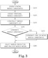
- FIG. 3 is a flow chart illustrating a method of encoding motion information in the merge mode according to the present invention.
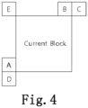
- FIG. 4 is a conceptual diagram illustrating positions of spatial merge candidate blocks according to the present invention.
- the merge candidate block is a left block (block A), an above block (block B), an above-right block (block C), a left-below block (block D) or an above-left block (block E) of the current block.
- the blocks are prediction blocks.
- the above-left block(block E) is set as merge candidate block when one or more of the blocks A, B, C and D are unavailable.
- the motion information of an available merge candidate block N is set asa spatial merge candidate N. N is A, B, C, D or E.
- the spatial merge candidate may be set as unavailable according to the shape of the current block and the position of the current block. For example, if the coding unit is split into two prediction units (block P0 and block P1) using asymmetric partitioning, it is probable that the motion information of the block P0 is not equal to the motion information of the block P1. Therefore, if the current block is the asymmetric block P1, the block P0 is set as unavailable candidate block as shown in FIGS. 5 to 8 .
- FIG. 5 is a conceptual block diagram illustrating positions of spatial merge candidate blocks according to the present invention.
- a coding unit is partitioned into two asymmetric prediction blocks P0 and P1 and the partitioning mode is an nLx2N mode.
- the size of the block P0 is hNx2N and the size of the block P1 is (2-h)Nx2N.
- the value of h is 1/2.
- the current block is the block P1.
- the blocks A, B, C, D and E are spatial merge candidate blocks.
- the block P0 is the spatial merge candidate block A.
- the spatial merge candidate A is set as unavailable not to be listed on the merge candidate list. Also, the spatial merge candidate block B, C, D or E having the same motion information of the spatial merge candidate block A is set as unavailable.
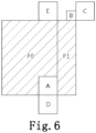
- FIG. 6 is another conceptual block diagram illustrating positions of spatial merge candidate blocks according to the present invention.
- a coding unit is partitioned into two asymmetric prediction blocks P0 and P1 and the partitioning mode is an nRx2N mode.
- the size of the block P0 is (2-h)Nx2N and the size of the block P1 is hNx2N.
- the value of h is 1/2.
- the current block is the block P1.
- the blocks A, B, C, D and E are spatial merge candidate blocks.
- the block P0 is the spatial merge candidate block A.
- the spatial merge candidate A is set as unavailable not to be listed on the merge candidate list. Also, the spatial merge candidate block B, C, D or E having the same motion information of the spatial merge candidate block A is set as unavailable.
- FIG. 7 is another conceptual block diagram illustrating positions of spatial merge candidate blocks according to the present invention.
- a coding unit is partitioned into two asymmetric prediction blocks P0 and P1 and the partitioning mode is a 2NxnU mode.
- the size of the block P0 is 2NxhN and the size of the block P1 is 2Nx(2-h)N.
- the value of h is 1/2.
- the current block is the block P1.
- the blocks A, B, C, D and E are spatial merge candidate blocks.
- the block P0 is the spatial merge candidate block B.
- the spatial merge candidate B is set as unavailable not to be listed on the merge candidate list. Also, the spatial merge candidate block C, D or E having the same motion information of the spatial merge candidate block B is set as unavailable.
- FIG. 8 is another conceptual block diagram illustrating positions of spatial merge candidate blocks according to the present invention.
- a coding unit is partitioned into two asymmetric prediction blocks P0 and P1 and the partitioning mode is a 2NxnD mode.
- the size of the block P0 is 2Nx(2-h)N and the size of the block P1 is 2NxhN.
- the value of h is 1/2.
- the current block is the block P1.
- the blocks A, B, C, D and E are spatial merge candidate blocks.
- the block P0 is the spatial merge candidate block B.
- the spatial merge candidate B is set as unavailable not to be listed on the merge candidate list. Also, the spatial merge candidate block C, D or E having the same motion information of the spatial merge candidate block B is set as unavailable.
- the spatial merge candidate may also be set as unavailable based on merge area. If the current block and the spatial merge candidate block belong to same merge area, the spatial merge candidate block is set as unavailable.
- the merge area is a unit area in which motion estimation is performed and information specifying the merge area is included in a bit stream.
- a temporal merge candidate is derived (S220).
- the temporal merge candidate includes a reference picture index and a motion vector of the temporal merge candidate.
- the reference picture index of the temporal merge candidate may be derived using one or more reference picture indexes of neighboring block. For example, one of the reference picture indexes of a left neighboring block, an above neighboring block and a corner neighboring block is set as the reference picture index of the temporal merge candidate.
- the corner neighboring block is one of an above-right neighboring block, a left-below neighboring block and an above-left neighboring block.
- the reference picture index of the temporal merge candidate may be set to zero to reduce the complexity.
- the motion vector of the temporal merge candidate may be derived as follows.
- a temporal merge candidate picture is determined.
- the temporal merge candidate picture includes a temporal merge candidate block.
- Onetemporal merge candidate picture is used within a slice.
- Areference picture index of the temporal merge candidate picture may be set to zero.
- the current slice is a P slice
- one of the reference pictures of the reference picture list 0 is set as the temporal merge candidate picture.
- the current slice is a B slice
- one of the reference pictures of the reference picture lists 0 and 1 is set as the temporal merge candidate picture.
- a list indicator specifying whether the temporal merge candidate picture belongs to the reference picture lists 0 or 1 is included in a slice header if the current slice is a B slice.
- the reference picture index specifying the temporal merge candidate picture may be included in the slice header.
- the temporal merge candidate block may be a first candidate block or a second candidate block. If the first candidate block is available, the first candidate block is set as the temporal merge candidate block. If the first candidate block is unavailable, the second candidate block is set as the temporal merge candidate block. If the second candidate block is unavailable, the temporal merge candidate block is set as unavailable.
- FIG. 9 is a conceptual diagram illustrating position of temporal merge candidate block according to the present invention.
- the first merge candidate block may be a right-below corner block (block H) of the block C.
- the block C has same size and same location of the current block and is located within the temporal merge candidate picture.
- the second merge candidate block is a block covering an upper-left pixel of the center of the block C.
- the motion vector of the temporal merge candidate block is set as the motion vector of the temporal merge candidate.
- a merge candidate list is constructed (S230).
- the available spatial candidates and the available temporal candidate are listed in a predetermined order.
- the spatial merge candidates are listed up to four in the order of A, B, C, D and E.
- the temporal merge candidate may be listed between B and C or after the spatial candidates.
- merge candidate list If the number of merge candidates listed in the merge candidate list is smaller than a predetermined number of the merge candidates, one or more merge candidates are generated (S250). The generated merge candidate is listed after the last available merge candidate.
- the merge candidate may be generated by combining the list 0 motion information and the list 1 motion information. Multiple merge candidates may be generated if there are multiple combinations.
- One or more zero merge candidates may be added to the list. If the slice type is P, the zero merge candidate has only list 0 motion information. If the slice type is B, the zero merge candidate has list 0 motion information and list 1 motion information.
- a merge predictor is selected among the merge candidates of the merge list, a merge index specifying the merge predictor is encoded (S260).
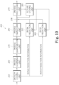
- FIG. 10 is a block diagram of an image decoding apparatus 200 according to the present invention.
- the image decoding apparatus 200 includes an entropy decoding unit 210, an inverse scanning unit 220, an inverse quantization unit 230, an inverse transform unit 240, an intra prediction unit 250, an inter prediction unit 260, a post-processing unit 270, a picture storing unit 280 and an adder 290.
- the entropy decoding unit 210 extracts the intra prediction information, the inter prediction information and the quantized coefficient components from a received bit stream using a context-adaptive binary arithmetic decoding method.
- the inverse scanning unit 220 applies an inverse scan pattern to the quantized coefficient components to generate quantized block.
- the inverse scan pattern is a diagonal scan.
- the quantized coefficient components include the significant flags, the coefficient signs and the coefficients levels.
- the significant flags, the coefficient signs and the coefficients levels are inversely scanned in the unit of subset using the diagonal scan to generate subsets, and the subsets are inversely scanned using the diagonal scan to generate the quantized block.
- the predetermined size is equal to the size of the subset.
- the subset is a 4x4 block including 16 transform coefficients.
- the significant flags, the coefficient signs and the coefficient levels are inversely scanned in the reverse direction.
- the subsets are also inversely scanned in the reverse direction.
- a parameter indicating last non-zero coefficient position and the non-zero subset flags are extracted from the bit stream.
- the number of encoded subsets is determined based on the last non-zero coefficient position.
- the non-zero subset flag is used to determine whether the correnpondingsubset has at least one non-zero coefficient. If the non-zero subset flag is equal to 1, the subset is generated using the diagonal scan. The first subset and the last subset are generated using the inverse scan pattern.
- the inverse quantization unit 230 receives the differential quantization parameter from the entropy decoding unit 210 and generates the quantization parameter predictor to generate the quantization parameter of the coding unit.
- the operation of generating the quantization parameter predictor is the same as the operation of the quantization unit 150 of FIG. 1 .
- the quantization parameter of the current coding unit is generated by adding the differential quantization parameter and the quantization parameter predictor. If the differential quantization parameter is not transmitted from an encoding side, the differential quantization parameter is set to zero.
- the inverse quantization unit 230 inversely quantizes the quantized block.
- the inverse transform unit 240 inversely transforms the inverse-quantized block to generate a residual block.
- An inverse transform matrix is adaptively determined according to the prediction mode and the size of the transform unit.
- the inverse transform matrix is a DCT-based integer transform matrix or a DST-based integer transform matrix. In inter prediction,the DCT-based integer transforms are used.
- the intra prediction unit 250 derivesanintra prediction mode of acurrent prediction unitusing the received intra prediction information, and generates a prediction block according to the derived intra prediction mode.
- the inter prediction unit 260 derives the motion information of the current prediction unit using the received inter prediction information, and generates a prediction block using the motion information.
- the post-processing unit 270 operates the same as the post-processing unit 180 of FIG. 1 .
- the picture storing unit 280 receives post-processed image from the post-processing unit 270, and stores the image in picture units.
- a picture may be a frame or a field.
- the adder 290 adds the restored residual block and a prediction block to generate a reconstructed block.
- FIG. 11 is a flow chart illustrating a method of decoding an image in inter prediction mode according to the present invention.
- Motion information of a current block is derived (S310).
- the current block is a prediction unit.
- a size of the current block is determined by the size of the coding unit and the partitioning mode.
- the motion information varies according to a prediction type. If the prediction type is a uni-directional prediction, the motion information includes a reference index specifying a picture of a reference list 0, and a motion vector. If the prediction type is a bi-directional prediction, the motion information includes a reference index specifying a picture of a reference list 0, a reference index specifying a picture of a reference list 1, and a list 0 motion vector and a list 1 motion vector.
- the motion information is adaptively decoded according the coding mode of the motion information.
- the coding mode of the motion information is determined by a skip flag and a merge flag. If the skip flag is equal to 1, the merge flag does not exist and the coding mode is a skip mode. If the skip flag is equal to 0 and the merge flag is equal to 1, the coding mode is a merge mode. If the skip flag and the merge flag are equal to 0, the coding mode is an AMVP mode.
- a prediction block of the current block is generated using the motion information (S320).
- the prediction block is generated by copying a block of the reference picture specified by the motion vector. If the motion vector indicates a sub-pixel position, the prediction block is generated by interpolating the pixels of the reference picture.
- a residual block is generated (S330).
- the residual block is generated by the entropy decoding unit 210, the inverse scanning unit 220, the inverse quantization unit 230 and the inverse transform unit 240 of FIG. 10 .
- Areconstructed block is generated using the prediction block and the residual block (S340).
- the prediction block has the same size of the prediction unit, and the residual block has the same size of the transform unit. Therefore, the residual signals and the prediction signals of same size are added to generate reconstructed signals.
- FIG. 12 is a flow chart illustrating a method of deriving motion information in merge mode.
- a merge index is extracted from a bit stream (S410). If the merge index does not exist, the number of merge candidates is set to one.
- Spatial merge candidates are derived (S420).
- the available spatial merge candidates are the same as describe in S210 of FIG. 3 .
- Atemporal merge candidate is derived (S430).
- the temporal merge candidate includes a reference picture index and a motion vector of the temporal merge candidate.
- the reference index and the motion vector of the temporal merge candidate are the same as described in S220 of FIG.3 .
- a merge candidate list is constructed (S440).
- the merge list is the same as described in S230 of FIG. 3 .
- merge candidate list If the number of merge candidates listed in the merge candidate list is smaller than a predetermined number of the merge candidates, one or more merge candidates are generated (S460).
- the generated merge candidate is listed after the last available merge candidate.
- the merge candidate is generated as the same method described in S250 of FIG. 3 .
- the merge candidate specified by the merge index is set as the motion information of the current block (S470).
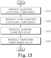
- FIG. 13 is a flow chart illustrating a procedure of generating a residual block in inter prediction mode according to the present invention.
- Quantized coefficient components are generated by the entropy decoding unit (S510).
- a quantized block is generated by inversely scanning the quantized coefficient components according to the diagonal scan (S520).
- the quantized coefficient components include the significant flags, the coefficient signs and the coefficients levels.
- the significant flags, the coefficient signs and the coefficients levels are inversely scanned in the unit of subset using the diagonal scan to generate subsets, and the subsets are inversely scanned using the diagonal scan to generate the quantized block.
- the predetermined size is equal to the size of the subset.
- the subset is a 4x4 block including 16 transform coefficients.
- the significant flags, the coefficient signs and the coefficient levels are inversely scanned in the reverse direction.
- the subsets are also inversely scanned in the reverse direction.
- the parameter indicating last non-zero coefficient position and the non-zero subset flags are extracted from the bit stream.
- the number of encoded subsets is determined based on the last non-zero coefficient position.
- the non-zero subset flag is used to determine whether the correnpondingsubset has at least one non-zero coefficient. If the non-zero subset flag is equal to 1, the subset is generated using the diagonal scan. The first subset and the last subset are generated using the inverse scan pattern.
- the quantized block is inversely quantized using an inverse quantization matrix and a quantization parameter (S530).
- FIG. 14 is a flow chart illustrating a method of deriving a quantization parameter according to the present invention.
- Aminimum size of quantization unit is determined (S531).
- a parameter cu_qp_delta_enabled_infospecifying the minimum size is extracted from a bit stream, and the minimum size of the quantization unit is determined by the following equation.
- Log 2 MinQUSize Log 2 MaxCUSize ⁇ cu _ qp _ delta_enabled _ info
- the MinQUSize indicates the minimum size of the quantization unit
- the MaxCUSize indicates the size of LCU.
- the parameter cu_qp_delta_enabled_info is extracted from a picture parameter set.
- a differential quantization parameter of the current coding unit is derived (S532).
- the differential quantization parameter is included per quantization unit. Therefore, if the size of the current coding unit is equal to or larger than the minimum size, the differential quantization parameter for the current coding unit is restored. If the differential quantization parameter does not exist, the differential quantization parameter is set to zero. If multiple coding units belong to a quantization unit, the first coding unit containing at least one non-zero coefficient in the decoding order contains the differential quantization unit.
- a coded differential quantization parameter is arithmetically decoded to generate bin string indicating the absolute value of the differential quantization parameter and a bin indicating the sign of the differential quantization parameter.
- the bin string may be a truncated unary code. If the absolute value of the differential quantization parameter is zero, the bin indicating the sign does not exist.
- the differential quantization parameter is derived using the bin string indicating the absolute value and the bin indicating the sign.
- a quantization parameter predictor of the current coding unit is derived (S533).
- the quantization parameter predictor is generated by using quantization parameters of neighboring coding units and quantization parameter of previous coding unit as follows.
- a left quantization parameter, an above quantization parameter and a previous quantization parameter are sequentially retrieved in this order.
- An average of the first two available quantization parameters retrieved in that order is set as the quantization parameter predictor when two or more quantization parameters are available, and when only one quantization parameter is available, the available quantization parameter is set as the quantization parameter predictor. That is, if the left and above quantization parameter are available, the average of the left and above quantization parameter is set as the quantization parameter predictor. If only one of the left and above quantization parameter is available, the average of the available quantization parameter and the previous quantization parameter is set as the quantization parameter predictor. If both of the left and above quantization parameter are unavailable, the previous quantization parameter is set as the quantization parameter predictor.
- the quantization parameter predictor for the first coding unit in decoding order is derived and used for the other coding units.
- the quantization parameter of the current coding unit is generated using the differential quantization parameter and the quantization parameter predictor (S534).
- a residual block is generated by inverse-transforming the inverse-quantized block (S540).
- One dimensional horizontal and vertical inverse DCT based-transforms are used.
Description
- The present invention relates to a method of constructing merge list, and more particularly, to a method of deriving spatial merge candidates based on a size and a partition index of a prediction unit and deriving a temporal merge candidate.
- Methods for compressing video data include MPEG-2, MPEG-4 and H.264/MPEG-4 AVC. According to these methods, one picture is divided into macroblocks to encode an image, the respective macroblocks are encoded by generating a prediction block using inter prediction or intra prediction. The difference between an original block and the prediction block is transformed to generate a transformed block, and the transformed block is quantized using a quantization parameter and one of a plurality of predetermined quantization matrices. The quantized coefficient of the quantized block are scanned by a predetermined scan type and then entropy-coded. The quantization parameteris adjusted per macroblock and encoded using a previous quantization parameter.
- In H.264/MPEG-4 AVC, motion estimation is used to eliminate temporal redundancy between consecutive pictures. To detect the temporal redundancy, one or more reference pictures are used to estimate motion of a current block, and motion compensation is performed to generate a prediction block using motion information. The motion information includes one or more reference picture indexes and one or more motion vectors. The motion vector of the motion information is predictively encoded using neighboring motion vectors, and the reference picture indexes are encoded without neighboring reference picture indexes.
- However, if various sizes are used for inter prediction, the correlation between motion information of a current block and motion information of one or more neighboring block increases. Also, if a motion of a current block is similar to or same as one of neighboring blocks, it is more effective to predictively encode the motion information using motion information of the neighboring blocks.
- The present invention is directed to a method of deriving spatial merge candidates based on a size and a partition index of a prediction unit and deriving a temporal merge candidate to construct merge list.
- SUGIO T ET AL: "Parsing Robustness for Merge/AMVP", 6. JCT-VC MEETING; 97. MPEG MEETING; 14-7-2011 - 22-7-2011; TORINO; (JOINT COLLABORATIVE TEAM ON VIDEO CODING OF ISO/ IEC JTC1/SC29/WG11 AND ITU-T SG.16); URL: HTTP://WFTP3.ITU.INT/ AV-ARCH/JCTVC-SITE/ discloses an approach to solve the parsing problem related to Merge/AMVP in HM3.0. The proposed approach uses fixed list length of Merge/AMVP candidates to decouple Merge/AMVP candidate list derivation and Merge/AMVP indices parsing. Moreover, in order to compensate the coding performance loss caused by the fixed list length, additional Merge/AMVP candidates are assigned to the empty positions in the list.
- I-K KIM ET AL: "CE2: Test result of asymmetric motion partition (AMP)", 6. JCT-VC MEETING; 97. MPEG MEETING; 14-7-2011 - 22-7-2011; TORINO; (JOINT COLLABORATIVE TEAM ON VIDEO CODING OF ISO/ IEC JTC1/SC29/WG11 AND ITU-T SG.16); URL: HTTP://WFTP3.ITU.INT/ AV-ARCH/JCTVC-SITE/ discloses test results of asymmetric motion partition (AMP). With encoding speedup, the average gain is 0.6% with 12% encoding and 1% decoding time decrease.
- It is therefore the object of the claimed invention to provide an improved method of constructing a merge candidate list for video coding.
- This object is solved by the subject matter of the independent claims.
- Preferred embodiments are defined by the dependent claims.
- One aspect of the present invention provides amethod of constructing a merge candidate list, comprising:checking availability of spatial merge candidates, checking availability of a temporal merge candidate, constructing the merge candidate list using available spatial and temporal merge candidates, and adding one or more candidates if the number of available spatial and temporal merge candidates is smaller than a predetermined number. The spatial merge candidate is motion information of a spatial merge candidate block, the spatial merge candidate block is a left block, an above block, an above-right block, a left-below block or an above-left block of the current block, and if the current block is a second prediction unit partitioned by asymmetric partitioning, the spatial merge candidate corresponding to a first prediction unit partitioned by the asymmetric partitioning is set as unavailable.
- A method according to the present inventionchecks availability of spatial and temporal merge candidates and constructs the merge candidate list using available spatial and temporal merge candidates, and adds one or more candidates if the number of available spatial and temporal merge candidates is smaller than a predetermined number. The spatial merge candidate is motion information of a spatial merge candidate block, the spatial merge candidate block is a left block, an above block, an above-right block, a left-below block or an above-left block of the current block, and if the current block is a second prediction unit partitioned by asymmetric partitioning, the spatial merge candidate corresponding to a first prediction unit partitioned by the asymmetric partitioning is set as unavailable. Also, the coding efficiency of residual block is improved by adaptively adjusting a quantization parameter per a quantization unit and generating a quantization parameter predictor using multiple neighboring quantization parameters.
-
-
FIG. 1 is a block diagram of an image coding apparatus according to the present invention. -
FIG. 2 is a flow chart illustrating a procedure of encoding video data according to the present invention. -
FIG. 3 is a flow chart illustrating a method of encoding motion information in the merge mode according to the present invention. -
FIG. 4 is a conceptual diagram illustrating positions of spatial merge candidate blocks according to the present invention. -
FIG. 5 is a conceptual block diagram illustrating positions of spatial merge candidate blocks according to the present invention. -
FIG. 6 is another conceptual block diagram illustrating positions of spatial merge candidate blocks according to the present invention. -
FIG. 7 is another conceptual block diagram illustrating positions of spatial merge candidate blocks according to the present invention. -
FIG. 8 is another conceptual block diagram illustrating positions of spatial merge candidate blocks according to the present invention. -
FIG. 9 is a conceptual diagram illustrating position of temporal merge candidate block according to the present invention. -
FIG. 10 is a block diagram of an image decoding apparatus according to the present invention. -
FIG. 11 is a flow chart illustrating a method of decoding an image in inter prediction mode according to the present invention. -
FIG. 12 is a flow chart illustrating a method of deriving motion information in merge mode. -
FIG. 13 is a flow chart illustrating a procedure of generating a residual block in inter prediction mode according to the present invention. -
FIG. 14 is a flow chart illustrating a method of deriving a quantization parameter according to the present invention. - Hereinafter, various embodiments of the present invention will be described in detail with reference to the accompanying drawings. However, the present invention is not limited to the exemplary embodiments disclosed below, but can be implemented in various types. Therefore, many other modifications and variations of the present invention are possible, and it is to be understood that within the scope of the disclosed concept, the present invention may be practiced otherwise than as has been specifically described.
- An image encoding apparatus and an image decoding apparatus according to the present invention may be a user terminal such as a personal computer, a personal mobile terminal, a mobile multimedia player, a smartphone or a wireless communication terminal. The image encoding device and the image decoding device may be include a communication unit for communicating with various devices, a memory for storing various programs and data used to encode or decode images.
-
FIG. 1 is a block diagram of animage coding apparatus 100 according to the present invention. - Referring to
FIG. 1 , theimage coding apparatus 100 according to the present invention includes apicture division unit 110, anintra prediction unit 120, aninter prediction unit 130, atransform unit 140, aquantization unit 150, ascanning unit 160, anentropy coding unit 170, an inverse quantization/transform unit 180, apost-processing unit 190 and apicture storing unit 195. - The
picture division unit 110 divides a picture or a slice into a plurality of largest coding units (LCUs), and divides each LCU into one or more coding units. The size of LCU may be 32x32, 64x64 or 128x128. Thepicture division unit 110 determines prediction mode and partitioning mode of each coding unit. - An LCU includes one or more coding units. The LCU has a recursive quad tree structure to specify a division structure of the LCU. Parameters for specifying the maximum size and the minimum size of the coding unit are included in a sequence parameter set. The division structure is specified by one or more split coding unit flags (split_cu_flags). The size of acoding unit is 2Nx2N. If the size of the LCU is 64x64 and the size of a smallest coding unit (SCU) is 8x8, the size of the coding unit may be 64x64, 32x32, 16x16 or 8x8.
- A coding unit includes one or more prediction units. In intra prediction, the size of the prediction unit is 2Nx2N or NxN. In inter prediction, the size of the prediction unit is specified by the partitioning mode. The partitioning mode is one of 2Nx2N,2NxN, Nx2N andNxN if the coding unit is partitioned symmetrically. The partitioning mode is one of 2NxnU, 2NxnD, nLx2N and nRx2N if the coding unit is partitionedasymmetrically. The partitioning modes are allowed based on the size of the coding unit to reduce complexity of hardware. If the coding unit has a minimum size, the asymmetric partitioning may not be allowed. Also, if the coding unit has the minimum size, NxN partitioning mode may not be allowed.
- A coding unit includes one or more transform units. The transform unit has a recursive quad tree structure to specify a division structure of the coding unit. The division structure is specified by one or more split transform unit flags (split_tu_flags). Parameters for specifying the maximum size and the minimum size of the lumatransform unit are included in a sequence parameter set.
- The
intra prediction unit 120 determines an intra prediction mode of a current prediction unit and generates a prediction block using the intra prediction mode. - The
inter prediction unit 130 determines motion information of a current prediction unit using one or more reference pictures stored in thepicture storing unit 195, and generates a prediction block of the prediction unit. The motion information includes one or more reference picture indexes and one or more motion vectors. - The
transform unit 140 transforms a residual block to generate a transformed block. The residual block has the same size of the transform unit. If the prediction unit is larger than the transform unit, the residual signals between the current block and the prediction block are partitioned into multiple residual blocks. - The
quantization unit 150 determines a quantization parameter for quantizing the transformed block. The quantization parameter is a quantization step size. The quantization parameter is determined per quantization unit. The size of the quantization unit may vary and be one of allowable sizes of coding unit. If a size of the coding unit is equal to or larger than theminimum size of thequantization unit, the coding unit becomes the quantization unit. A plurality of coding units may be included in a quantization unit of minimum size. Theminimum size of the quantization unit is determined per picture and a parameter for specifying the minimum size of thequantization unit is included in a picture parameter set. - The
quantization unit 150 generates a quantization parameter predictor and generates a differential quantization parameter by subtracting the quantization parameter predictor from the quantizationparameter. The differential quantization parameter is entropy-coded. - The quantization parameter predictor is generated by using quantization parameters of neighboring coding units and a quantization parameter of previous coding unit as follows.
- A left quantization parameter, an above quantization parameter and a previous quantization parameter are sequentially retrieved in this order. An average of the first two available quantization parameters retrieved in that order is set as the quantization parameter predictor when two or more quantization parameters are available, and when only one quantization parameter is available, the available quantization parameter is set as the quantization parameter predictor. That is, if the left and above quantization parameters are available, an average of the left and above quantization parameters is set as the quantization parameter predictor. If only one of the left and above quantization parameters is available, an average of the available quantization parameter and the previous quantization parameters is set as the quantization parameter predictor. If both of the left and above quantization parameters are unavailable, the previous quantization parameter is set as the quantization parameter predictor. The average is rounded off.
- The differential quantization parameter is converted into bins for the absolute value of the differential quantization parameter and a bin for indicating sign of the differential quantization parameter through a binarization process, and the bins are arithmetically coded. If the absolute value of the differential quantization parameter is 0, the bin for indicating sign may be omitted. Truncated unary is used for binarization of the absolute.
- The
quantization unit 150 quantizes the transformed block using a quantization matrix and the quantization parameter to generate a quantized block. The quantized block is provided to the inverse quantization/transform unit 180 and thescanning unit 160. - The
scanning unit 160 determines applies a scan pattern to the quantized block. - In inter prediction, a diagonal scan is used as the scan pattern if CABAC is used for entropy coding. The quantized coefficients of the quantized block are split into coefficient components. The coefficient components are significant flags, coefficient signs and coefficient levels. The diagonal scan is applied to each of the coefficient components. The significant coefficient indicates whether the corresponding quantized coefficient is zero or not. The coefficient sign indicates a sign of non-zero quantized coefficient, and the coefficient level indicates an absolute value of non-zero quantized coefficient.
- When the size of the transform unit is larger than a predetermined size, the quantized block is divided into multiple subsetsand the diagonal scan is applied to each subset. Significant flags, coefficient signs and coefficients levels of each subset are scanned respectively according to the diagonal scan. Thepredetermined size is 4x4. The subset is a 4x4 block containing 16 transform coefficients.
- The scan pattern for scanning the subsets is the same as the scan pattern for scanning the coefficient components. The significant flags, the coefficient signs and the coefficients levels of each subset are scannedin the reverse direction. The subsets are also scanned in the reverse direction.
- A parameter indicating last non-zero coefficient positionis encoded and transmitted to a decoding side. The parameter indicating last non-zero coefficient position specifies a position of last non-zero quantized coefficient within the quantized block.A non-zero subset flag is defined for each subset other than the first subset and the last subset and is transmitted to the decoding side. The first subset covers a DC coefficient. The last subset covers the last non-zero coefficient.The non-zero subset flag indicates whether the subset contains non-zero coefficients or not.
- The
entropy coding unit 170 entropy-codes the scanned componentby thescanning unit 160, intra prediction information received from theintra prediction unit 120, motion information received from theinter prediction unit 130, and so on. - The inverse quantization/
transform unit 180 inversely quantizes the quantized coefficients of the quantized block, and inversely transforms the inverse quantized block to generate residual block. - The
post-processing unit 190 performs a deblocking filtering process for removing blocking artifact generated in a reconstructed picture. - The
picture storing unit 195 receives post-processed image from thepost-processing unit 190, and stores the image in picture units. A picture may be a frame or a field. -
FIG. 2 is a flow chart illustrating a method of encoding video datain an inter prediction mode according to the present invention. - Motion information of a current block is determined (S110). The current block is a prediction unit. A size of the current block is determined by a size and a partitioning mode of the coding unit.
- The motion information varies according to a prediction type. If the prediction type is a uni-directional prediction, the motion information includes a reference index specifying a picture of a reference list 0, and a motion vector. If the prediction type is a bi-directional prediction, the motion information includes two reference indexes specifying a picture of a reference list 0 and a picture of a reference list 1, and a list 0 motion vector and a list 1 motion vector.
- Aprediction block of the current block is generated using the motion information (S120). If the motion vector indicates a pixel position, the prediction block is generated by copying a block of the reference picture specified by the motion vector. If the motion vector indicates a sub-pixel position, the prediction block is generated by interpolating the pixels of the reference picture.
- A residual block is generated using the current block and the prediction block (S130). The residual block has the same size of the transform unit. If the prediction unit is larger than the transform unit, the residual signals between the current block and the prediction block are into multiple residual blocks.
- The residual block is encoded (S140). The residual block is encoded by the
transform unit 140, thequantization unit 150, thescanning unit 160 and theentropy coding unit 170 ofFIG. 1 . - The motion information is encoded (S150). The motion information may be encoded predictively using spatial candidates and a temporal candidate of the current block. The motion information is encoded in a skip mode, a merge mode or an AMVP mode. In the skip mode, the prediction unit has the size of coding unit and the motion information is encoded using the same method as that of the merge mode. In the merge mode, the motion information of the current prediction unit is equal to motion information of one candidate. In the AMVP mode, the motion vector of the motion information is predictively coded using one or more motion vector candidate.
-
FIG. 3 is a flow chart illustrating a method of encoding motion information in the merge mode according to the present invention. - Spatial merge candidates are derived (S210).
FIG. 4 is a conceptual diagram illustrating positions of spatial merge candidate blocks according to the present invention. - As shown in
FIG. 4 , the merge candidate block is a left block (block A), an above block (block B), an above-right block (block C), a left-below block (block D) or an above-left block (block E) of the current block. The blocks are prediction blocks. The above-left block(block E) is set as merge candidate block when one or more of the blocks A, B, C and D are unavailable. The motion information of an available merge candidate block N is set asa spatial merge candidate N. N is A, B, C, D or E. - The spatial merge candidate may be set as unavailable according to the shape of the current block and the position of the current block. For example, if the coding unit is split into two prediction units (block P0 and block P1) using asymmetric partitioning, it is probable that the motion information of the block P0 is not equal to the motion information of the block P1. Therefore, if the current block is the asymmetric block P1, the block P0 is set as unavailable candidate block as shown in
FIGS. 5 to 8 . -
FIG. 5 is a conceptual block diagram illustrating positions of spatial merge candidate blocks according to the present invention. - As shown in
FIG. 5 , a coding unit is partitioned into two asymmetric prediction blocks P0 and P1 and the partitioning mode is an nLx2N mode. The size of the block P0 is hNx2N and the size of the block P1 is (2-h)Nx2N. The value of h is 1/2. The current block is the block P1. The blocks A, B, C, D and E are spatial merge candidate blocks. The block P0 is the spatial merge candidate block A. - In present invention, the spatial merge candidate A is set as unavailable not to be listed on the merge candidate list. Also, the spatial merge candidate block B, C, D or E having the same motion information of the spatial merge candidate block A is set as unavailable.
-
FIG. 6 is another conceptual block diagram illustrating positions of spatial merge candidate blocks according to the present invention. - As shown in
FIG. 6 , a coding unit is partitioned into two asymmetric prediction blocks P0 and P1 and the partitioning mode is an nRx2N mode. The size of the block P0 is (2-h)Nx2N and the size of the block P1 is hNx2N. The value of h is 1/2. The current block is the block P1. The blocks A, B, C, D and E are spatial merge candidate blocks. The block P0 is the spatial merge candidate block A. - In present invention, the spatial merge candidate A is set as unavailable not to be listed on the merge candidate list. Also, the spatial merge candidate block B, C, D or E having the same motion information of the spatial merge candidate block A is set as unavailable.
-
FIG. 7 is another conceptual block diagram illustrating positions of spatial merge candidate blocks according to the present invention. - As shown in
FIG. 7 , a coding unit is partitioned into two asymmetric prediction blocks P0 and P1 and the partitioning mode is a 2NxnU mode. The size of the block P0 is 2NxhN and the size of the block P1 is 2Nx(2-h)N. The value of h is 1/2. The current block is the block P1. The blocks A, B, C, D and E are spatial merge candidate blocks. The block P0 is the spatial merge candidate block B. - In present invention, the spatial merge candidate B is set as unavailable not to be listed on the merge candidate list. Also, the spatial merge candidate block C, D or E having the same motion information of the spatial merge candidate block B is set as unavailable.
-
FIG. 8 is another conceptual block diagram illustrating positions of spatial merge candidate blocks according to the present invention. - As shown in
FIG. 8 , a coding unit is partitioned into two asymmetric prediction blocks P0 and P1 and the partitioning mode is a 2NxnD mode. The size of the block P0 is 2Nx(2-h)N and the size of the block P1 is 2NxhN. The value of h is 1/2. The current block is the block P1. The blocks A, B, C, D and E are spatial merge candidate blocks. The block P0 is the spatial merge candidate block B. - In present invention, the spatial merge candidate B is set as unavailable not to be listed on the merge candidate list. Also, the spatial merge candidate block C, D or E having the same motion information of the spatial merge candidate block B is set as unavailable.
- The spatial merge candidate may also be set as unavailable based on merge area. If the current block and the spatial merge candidate block belong to same merge area, the spatial merge candidate block is set as unavailable. The merge area is a unit area in which motion estimation is performed and information specifying the merge area is included in a bit stream.
- A temporal merge candidate is derived (S220). The temporal merge candidate includes a reference picture index and a motion vector of the temporal merge candidate.
- The reference picture index of the temporal merge candidate may be derived using one or more reference picture indexes of neighboring block. For example, one of the reference picture indexes of a left neighboring block, an above neighboring block and a corner neighboring block is set as the reference picture index of the temporal merge candidate. The corner neighboring block is one of an above-right neighboring block, a left-below neighboring block and an above-left neighboring block. Alternatively, the reference picture index of the temporal merge candidate may be set to zero to reduce the complexity.
- The motion vector of the temporal merge candidate may be derived as follows.
- First, a temporal merge candidate picture is determined. The temporal merge candidate picture includes a temporal merge candidate block. Onetemporal merge candidate picture is used within a slice. Areference picture index of the temporal merge candidate picture may be set to zero.
- If the current slice is a P slice, one of the reference pictures of the reference picture list 0 is set as the temporal merge candidate picture. If the current slice is a B slice, one of the reference pictures of the reference picture lists 0 and 1 is set as the temporal merge candidate picture. A list indicator specifying whether the temporal merge candidate picture belongs to the reference picture lists 0 or 1 is included in a slice header if the current slice is a B slice. The reference picture index specifying the temporal merge candidate picture may be included in the slice header.
- Next, the temporal merge candidate block is determined. The temporal merge candidate block may be a first candidate block or a second candidate block. If the first candidate block is available, the first candidate block is set as the temporal merge candidate block. If the first candidate block is unavailable, the second candidate block is set as the temporal merge candidate block. If the second candidate block is unavailable, the temporal merge candidate block is set as unavailable.
-
FIG. 9 is a conceptual diagram illustrating position of temporal merge candidate block according to the present invention. As shown inFIG. 9 , the first merge candidate block may be a right-below corner block (block H) of the block C. The block C has same size and same location of the current block and is located within the temporal merge candidate picture. The second merge candidate block is a block covering an upper-left pixel of the center of the block C. - If the temporal merge candidate block is determined, the motion vector of the temporal merge candidate block is set as the motion vector of the temporal merge candidate.
- A merge candidate list is constructed (S230). The available spatial candidates and the available temporal candidate are listed in a predetermined order. The spatial merge candidates are listed up to four in the order of A, B, C, D and E. The temporal merge candidate may be listed between B and C or after the spatial candidates.
- It is determined whether one or more merge candidates are generated or not (S240). The determination is performed by comparing the number of merge candidates listed in the merge candidate list with a predetermined number of the merge candidates. The predetermined number may be determined per picture or slice.
- If the number of merge candidates listed in the merge candidate list is smaller than a predetermined number of the merge candidates, one or more merge candidates are generated (S250). The generated merge candidate is listed after the last available merge candidate.
- If the number of available merge candidates is equal to or greater than 2, one of two available merge candidates has list 0 motion information and the other has list 1 motion information, the merge candidate may be generated by combining the list 0 motion information and the list 1 motion information. Multiple merge candidates may be generated if there are multiple combinations.
- One or more zero merge candidates may be added to the list. If the slice type is P, the zero merge candidate has only list 0 motion information. If the slice type is B, the zero merge candidate has list 0 motion information and list 1 motion information.
- A merge predictor is selected among the merge candidates of the merge list, a merge index specifying the merge predictor is encoded (S260).
-
FIG. 10 is a block diagram of animage decoding apparatus 200 according to the present invention. - The
image decoding apparatus 200 according to the present invention includes anentropy decoding unit 210, aninverse scanning unit 220, aninverse quantization unit 230, aninverse transform unit 240, anintra prediction unit 250, aninter prediction unit 260, apost-processing unit 270, apicture storing unit 280 and anadder 290. - The
entropy decoding unit 210 extracts the intra prediction information, the inter prediction information and the quantized coefficient components from a received bit stream using a context-adaptive binary arithmetic decoding method. - The
inverse scanning unit 220 applies an inverse scan pattern to the quantized coefficient components to generate quantized block. In inter prediction, the inverse scan pattern is a diagonal scan. The quantized coefficient components include the significant flags, the coefficient signs and the coefficients levels. - When the size of the transform unit is larger than the a predetermined size, the significant flags, the coefficient signs and the coefficients levels are inversely scanned in the unit of subset using the diagonal scan to generate subsets, and the subsets are inversely scanned using the diagonal scan to generate the quantized block.The predetermined size is equal to the size of the subset. The subset is a 4x4 block including 16 transform coefficients. The significant flags, the coefficient signs and the coefficient levels are inversely scanned in the reverse direction. The subsets are also inversely scanned in the reverse direction.
- A parameter indicating last non-zero coefficient position and the non-zero subset flags are extracted from the bit stream. The number of encoded subsets is determined based on the last non-zero coefficient position. The non-zero subset flag is used to determine whether the correnpondingsubset has at least one non-zero coefficient.If the non-zero subset flag is equal to 1, the subset is generated using the diagonal scan. The first subset and the last subset are generated using the inverse scan pattern.
- The
inverse quantization unit 230 receives the differential quantization parameter from theentropy decoding unit 210 and generates the quantization parameter predictor to generate the quantization parameter of the coding unit. The operation of generating the quantization parameter predictor is the same as the operation of thequantization unit 150 ofFIG. 1 . Then, the quantization parameter of the current coding unit is generated by adding the differential quantization parameter and the quantization parameter predictor. If the differential quantization parameter is not transmitted from an encoding side, the differential quantization parameter is set to zero. - The
inverse quantization unit 230 inversely quantizes the quantized block. - The
inverse transform unit 240 inversely transforms the inverse-quantized block to generate a residual block. An inverse transform matrix is adaptively determined according to the prediction mode and the size of the transform unit. The inverse transform matrix is a DCT-based integer transform matrix or a DST-based integer transform matrix. In inter prediction,the DCT-based integer transforms are used. - The
intra prediction unit 250 derivesanintra prediction mode of acurrent prediction unitusing the received intra prediction information, and generates a prediction block according to the derived intra prediction mode. - The
inter prediction unit 260 derives the motion information of the current prediction unit using the received inter prediction information, and generates a prediction block using the motion information. - The
post-processing unit 270 operates the same as thepost-processing unit 180 ofFIG. 1 . - The
picture storing unit 280 receives post-processed image from thepost-processing unit 270, and stores the image in picture units. A picture may be a frame or a field. - The
adder 290 adds the restored residual block and a prediction block to generate a reconstructed block. -
FIG. 11 is a flow chart illustrating a method of decoding an image in inter prediction mode according to the present invention. - Motion information of a current block is derived (S310). The current block is a prediction unit. A size of the current block is determined by the size of the coding unit and the partitioning mode.
- The motion information varies according to a prediction type. If the prediction type is a uni-directional prediction, the motion information includes a reference index specifying a picture of a reference list 0, and a motion vector. If the prediction type is a bi-directional prediction, the motion information includes a reference index specifying a picture of a reference list 0, a reference index specifying a picture of a reference list 1, and a list 0 motion vector and a list 1 motion vector.
- The motion information is adaptively decoded according the coding mode of the motion information. The coding mode of the motion information is determined by a skip flag and a merge flag. If the skip flag is equal to 1, the merge flag does not exist and the coding mode is a skip mode. If the skip flag is equal to 0 and the merge flag is equal to 1, the coding mode is a merge mode. If the skip flag and the merge flag are equal to 0, the coding mode is an AMVP mode.
- A prediction block of the current block is generated using the motion information (S320).
- If the motion vector indicates a pixel position, the prediction block is generated by copying a block of the reference picture specified by the motion vector. If the motion vector indicates a sub-pixel position, the prediction block is generated by interpolating the pixels of the reference picture.
- A residual block is generated (S330). The residual block is generated by the
entropy decoding unit 210, theinverse scanning unit 220, theinverse quantization unit 230 and theinverse transform unit 240 ofFIG. 10 . - Areconstructed block is generated using the prediction block and the residual block (S340).
- The prediction block has the same size of the prediction unit, and the residual block has the same size of the transform unit. Therefore, the residual signals and the prediction signals of same size are added to generate reconstructed signals.
-
FIG. 12 is a flow chart illustrating a method of deriving motion information in merge mode. - A merge index is extracted from a bit stream (S410). If the merge index does not exist, the number of merge candidates is set to one.
- Spatial merge candidates are derived (S420).The available spatial merge candidates are the same as describe in S210 of
FIG. 3 . - Atemporal merge candidate is derived (S430). The temporal merge candidate includes a reference picture index and a motion vector of the temporal merge candidate. The reference index and the motion vector of the temporal merge candidate are the same as described in S220 of
FIG.3 . - A merge candidate list is constructed (S440). The merge list is the same as described in S230 of
FIG. 3 . - It is determined whether one or more merge candidates are generated or not (S450). The determination is performed by comparing the number of merge candidates listed in the merge candidate list with a predetermined number of the merge candidates. The predetermined number is determined per picture or slice.
- If the number of merge candidates listed in the merge candidate list is smaller than a predetermined number of the merge candidates, one or more merge candidates are generated (S460). The generated merge candidate is listed after the last available merge candidate. The merge candidate is generated as the same method described in S250 of
FIG. 3 . - The merge candidate specified by the merge index is set as the motion information of the current block (S470).
-
FIG. 13 is a flow chart illustrating a procedure of generating a residual block in inter prediction mode according to the present invention. - Quantized coefficient components are generated by the entropy decoding unit (S510).
- A quantized block is generated by inversely scanning the quantized coefficient components according to the diagonal scan (S520). The quantized coefficient components include the significant flags, the coefficient signs and the coefficients levels.
- When the size of the transform unit is larger than a predetermined size, the significant flags, the coefficient signs and the coefficients levels are inversely scanned in the unit of subset using the diagonal scan to generate subsets, and the subsets are inversely scanned using the diagonal scan to generate the quantized block. The predetermined size is equal to the size of the subset. The subset is a 4x4 block including 16 transform coefficients. The significant flags, the coefficient signs and the coefficient levels are inversely scanned in the reverse direction. The subsets are also inversely scanned in the reverse direction.
- The parameter indicating last non-zero coefficient position and the non-zero subset flags are extracted from the bit stream. The number of encoded subsets is determined based on the last non-zero coefficient position. The non-zero subset flag is used to determine whether the correnpondingsubset has at least one non-zero coefficient. If the non-zero subset flag is equal to 1, the subset is generated using the diagonal scan. The first subset and the last subset are generated using the inverse scan pattern.
- The quantized block is inversely quantized using an inverse quantization matrix and a quantization parameter (S530).
-
FIG. 14 is a flow chart illustrating a method of deriving a quantization parameter according to the present invention. - Aminimum size of quantization unit is determined (S531). A parameter cu_qp_delta_enabled_infospecifying the minimum size is extracted from a bit stream, and the minimum size of the quantization unit is determined by the following equation.

- The MinQUSize indicates the minimum size of the quantization unit, the MaxCUSize indicates the size of LCU. The parameter cu_qp_delta_enabled_info is extracted from a picture parameter set.
- A differential quantization parameter of the current coding unit is derived (S532). The differential quantization parameter is included per quantization unit. Therefore, if the size of the current coding unit is equal to or larger than the minimum size, the differential quantization parameter for the current coding unit is restored. If the differential quantization parameter does not exist, the differential quantization parameter is set to zero. If multiple coding units belong to a quantization unit, the first coding unit containing at least one non-zero coefficient in the decoding order contains the differential quantization unit.
- A coded differential quantization parameter is arithmetically decoded to generate bin string indicating the absolute value of the differential quantization parameter and a bin indicating the sign of the differential quantization parameter. The bin string may be a truncated unary code. If the absolute value of the differential quantization parameter is zero, the bin indicating the sign does not exist. The differential quantization parameter is derived using the bin string indicating the absolute value and the bin indicating the sign.
- A quantization parameter predictor of the current coding unit is derived (S533). The quantization parameter predictor is generated by using quantization parameters of neighboring coding units and quantization parameter of previous coding unit as follows.
- A left quantization parameter, an above quantization parameter and a previous quantization parameter are sequentially retrieved in this order. An average of the first two available quantization parameters retrieved in that order is set as the quantization parameter predictor when two or more quantization parameters are available, and when only one quantization parameter is available, the available quantization parameter is set as the quantization parameter predictor. That is, if the left and above quantization parameter are available, the average of the left and above quantization parameter is set as the quantization parameter predictor. If only one of the left and above quantization parameter is available, the average of the available quantization parameter and the previous quantization parameter is set as the quantization parameter predictor. If both of the left and above quantization parameter are unavailable, the previous quantization parameter is set as the quantization parameter predictor.
- If multiple coding units belong to a quantization unit of minimum size, the quantization parameter predictor for the first coding unit in decoding order is derived and used for the other coding units.
- The quantization parameter of the current coding unit is generated using the differential quantization parameter and the quantization parameter predictor (S534).
- A residual block is generated by inverse-transforming the inverse-quantized block (S540). One dimensional horizontal and vertical inverse DCT based-transforms are used.
- While the invention has been shown and described with reference to certain exemplary embodiments thereof, it will be understood by those skilled in the art that various changes in form and details may be made therein without departing from the scope of the invention as defined by the appended claims.
Claims (8)
- A method of constructing a merge candidate list for video coding, comprising:constructing merge list;obtaining motion information using a merge index and the merge list;generating a prediction block using the motion information; andgenerating a quantization block by inverse-scanning quantized coefficient components according to diagonal scanning, inverse-quantizing the quantization block by using quantization parameter, and generating a residual block by inverse-transforming the inverse-quantized block,wherein the merge list is constructed by performing sub-steps of:checking availability of spatial merge candidates;checking availability of a temporal merge candidate;constructing the merge list using available spatial and temporal merge candidates; andadding one or more candidates if the number of available spatial and temporalmerge candidates is smaller than a predetermined number,wherein the spatial merge candidates are motion information of spatial merge candidate blocks, and the spatial merge candidate blocks are a left block, an above block, an above-right block, a left-below block or an above-left block of the current block,wherein if the current block is a second prediction unit partitioned by asymmetric partitioning, the spatial merge candidate corresponding to a first prediction unit partitioned by the asymmetric partitioning is set as unavailable,wherein the quantization parameter is generated using a differential quantization parameter and a quantization parameter predictor, and the quantization parameter predictor is generated by averaging the first two available quantization parameters in an order of a left quantization parameter, an above quantization parameter and a previous quantization parameter if two or more quantization parameters are available, andwherein, when only one of the left quantization parameter and the above quantization parameter is available, the quantization parameter is generated using an average of the available quantization parameter and a previous quantization parameter.
- The apparatus of claim 1, wherein if the size of the current block is (3/2)Nx2N, the left spatial merge candidate is set as unavailable.
- The apparatus of claim 2, wherein the left spatial merge candidate is motion information of the left prediction unit of the current block.
- The apparatus of claim 2, wherein if an above spatial merge candidate has the same motion information of the left spatial merge candidate, the above spatial merge candidate is set as unavailable.
- The apparatus of claim 2, wherein the size of the current block is determined based on a partitioning mode and a size of the coding unit.
- The method of claim 1, if a current coding unit has an allowed minimum size, the asymmetric partitioning is not allowed.
- The method of claim 1, wherein an available above-left block is set as a merge candidate block when at least one of the left block, the above block, the above-right block and the left-below block is not available.
- The method of claim 1, wherein a motion vector of the temporal merge candidate is a motion vector of a temporal merge candidate block within a temporal merge candidate picture.
Priority Applications (1)
| Application Number | Priority Date | Filing Date | Title |
|---|---|---|---|
| EP23176701.3A EP4224855A1 (en) | 2011-11-07 | 2012-11-07 | Method of constructing merge list |
Applications Claiming Priority (3)
| Application Number | Priority Date | Filing Date | Title |
|---|---|---|---|
| KR1020110115219A KR20130050406A (en) | 2011-11-07 | 2011-11-07 | Method for generating prediction block in inter prediction mode |
| PCT/CN2012/084240 WO2013067938A1 (en) | 2011-11-07 | 2012-11-07 | Method of constructing merge list |
| EP12848743.6A EP2752006B1 (en) | 2011-11-07 | 2012-11-07 | Method of constructing merge list |
Related Parent Applications (2)
| Application Number | Title | Priority Date | Filing Date |
|---|---|---|---|
| EP12848743.6A Division EP2752006B1 (en) | 2011-11-07 | 2012-11-07 | Method of constructing merge list |
| EP12848743.6A Division-Into EP2752006B1 (en) | 2011-11-07 | 2012-11-07 | Method of constructing merge list |
Related Child Applications (1)
| Application Number | Title | Priority Date | Filing Date |
|---|---|---|---|
| EP23176701.3A Division EP4224855A1 (en) | 2011-11-07 | 2012-11-07 | Method of constructing merge list |
Publications (2)
| Publication Number | Publication Date |
|---|---|
| EP3829176A1 EP3829176A1 (en) | 2021-06-02 |
| EP3829176B1 true EP3829176B1 (en) | 2023-06-07 |
Family
ID=48208141
Family Applications (6)
| Application Number | Title | Priority Date | Filing Date |
|---|---|---|---|
| EP23176701.3A Pending EP4224855A1 (en) | 2011-11-07 | 2012-11-07 | Method of constructing merge list |
| EP12848743.6A Active EP2752006B1 (en) | 2011-11-07 | 2012-11-07 | Method of constructing merge list |
| EP20216547.8A Active EP3829172B1 (en) | 2011-11-07 | 2012-11-07 | Method of constructing merge list |
| EP20216550.2A Active EP3829174B1 (en) | 2011-11-07 | 2012-11-07 | Method of constructing merge list |
| EP20216553.6A Active EP3829175B1 (en) | 2011-11-07 | 2012-11-07 | Method of constructing merge list |
| EP20216558.5A Active EP3829176B1 (en) | 2011-11-07 | 2012-11-07 | Method of constructing merge list |
Family Applications Before (5)
| Application Number | Title | Priority Date | Filing Date |
|---|---|---|---|
| EP23176701.3A Pending EP4224855A1 (en) | 2011-11-07 | 2012-11-07 | Method of constructing merge list |
| EP12848743.6A Active EP2752006B1 (en) | 2011-11-07 | 2012-11-07 | Method of constructing merge list |
| EP20216547.8A Active EP3829172B1 (en) | 2011-11-07 | 2012-11-07 | Method of constructing merge list |
| EP20216550.2A Active EP3829174B1 (en) | 2011-11-07 | 2012-11-07 | Method of constructing merge list |
| EP20216553.6A Active EP3829175B1 (en) | 2011-11-07 | 2012-11-07 | Method of constructing merge list |
Country Status (20)
| Country | Link |
|---|---|
| US (7) | US8917772B2 (en) |
| EP (6) | EP4224855A1 (en) |
| JP (6) | JP5823628B2 (en) |
| KR (5) | KR20130050406A (en) |
| CN (7) | CN108134933B (en) |
| BR (5) | BR112014007871B1 (en) |
| CY (1) | CY1123872T1 (en) |
| DK (5) | DK3829175T3 (en) |
| ES (5) | ES2859550T3 (en) |
| HR (1) | HRP20210659T1 (en) |
| HU (5) | HUE062049T2 (en) |
| IN (1) | IN2014CN03913A (en) |
| LT (1) | LT2752006T (en) |
| MX (6) | MX336815B (en) |
| PL (5) | PL3829176T3 (en) |
| PT (5) | PT3829172T (en) |
| RS (1) | RS61740B1 (en) |
| SI (1) | SI2752006T1 (en) |
| TW (1) | TWI537881B (en) |
| WO (1) | WO2013067938A1 (en) |
Families Citing this family (57)
| Publication number | Priority date | Publication date | Assignee | Title |
|---|---|---|---|---|
| CN106686378B (en) * | 2011-06-14 | 2019-10-08 | 三星电子株式会社 | The method and apparatus that image is decoded |
| KR20130050406A (en) | 2011-11-07 | 2013-05-16 | 오수미 | Method for generating prediction block in inter prediction mode |
| CN110198450B (en) * | 2011-11-08 | 2021-12-31 | 韩国电子通信研究院 | Method and apparatus for sharing a candidate list |
| EP2942961A1 (en) | 2011-11-23 | 2015-11-11 | HUMAX Holdings Co., Ltd. | Methods for encoding/decoding of video using common merging candidate set of asymmetric partitions |
| SI2802146T1 (en) | 2011-12-16 | 2019-07-31 | JVC Kenwood Corporation | Dynamic image decoding device, dynamic image decoding method, and dynamic image decoding program |
| JP5561348B2 (en) * | 2011-12-16 | 2014-07-30 | 株式会社Jvcケンウッド | Moving picture decoding apparatus, moving picture decoding method, moving picture decoding program, receiving apparatus, receiving method, and receiving program |
| JP5900308B2 (en) * | 2011-12-16 | 2016-04-06 | 株式会社Jvcケンウッド | Moving picture coding apparatus, moving picture coding method, and moving picture coding program |
| CN102883163B (en) * | 2012-10-08 | 2014-05-28 | 华为技术有限公司 | Method and device for building motion vector lists for prediction of motion vectors |
| CN104159106B (en) * | 2013-05-14 | 2017-12-01 | 联发科技股份有限公司 | Method for video coding and video encoding/decoding method and its device |
| US9832478B2 (en) | 2013-05-14 | 2017-11-28 | Mediatek Inc. | Video encoding method and apparatus for determining size of parallel motion estimation region based on encoding related information and related video decoding method and apparatus |
| JP6434012B2 (en) | 2013-07-24 | 2018-12-05 | クゥアルコム・インコーポレイテッドQualcomm Incorporated | Simplified advanced motion prediction for 3D-HEVC |
| US9948915B2 (en) | 2013-07-24 | 2018-04-17 | Qualcomm Incorporated | Sub-PU motion prediction for texture and depth coding |
| US9554150B2 (en) * | 2013-09-20 | 2017-01-24 | Qualcomm Incorporated | Combined bi-predictive merging candidates for 3D video coding |
| US20160286212A1 (en) * | 2013-10-17 | 2016-09-29 | Nippon Telegraph And Telephone Corporation | Video encoding apparatus and method, and video decoding apparatus and method |
| CN104768012B (en) * | 2014-01-03 | 2018-04-20 | 华为技术有限公司 | The method and encoding device of asymmetrical movement partitioning scheme coding |
| WO2015131387A1 (en) * | 2014-03-07 | 2015-09-11 | Qualcomm Incorporated | Simplified sub-prediction unit (sub-pu) motion parameter inheritence (mpi) |
| WO2015180014A1 (en) * | 2014-05-26 | 2015-12-03 | Mediatek Singapore Pte. Ltd. | An improved merge candidate list construction method for intra block copy |
| WO2016003074A1 (en) * | 2014-06-30 | 2016-01-07 | 한국전자통신연구원 | Device and method for eliminating redundancy of view synthesis prediction candidate in motion merge mode |
| KR102378459B1 (en) | 2014-06-30 | 2022-03-24 | 한국전자통신연구원 | Apparatus And Method For Eliminating Redundancy Of View Synthesis Prediction Candidate In Merge Mode |
| US10757437B2 (en) | 2014-07-17 | 2020-08-25 | Apple Inc. | Motion estimation in block processing pipelines |
| US9762919B2 (en) | 2014-08-28 | 2017-09-12 | Apple Inc. | Chroma cache architecture in block processing pipelines |
| US11477477B2 (en) * | 2015-01-26 | 2022-10-18 | Qualcomm Incorporated | Sub-prediction unit based advanced temporal motion vector prediction |
| US10666936B2 (en) | 2015-12-17 | 2020-05-26 | Samsung Electronics Co., Ltd. | Video decoding method and video decoding apparatus using merge candidate list |
| EP3407606B1 (en) * | 2016-02-11 | 2023-04-26 | Samsung Electronics Co., Ltd. | Video encoding method and device and video decoding method and device |
| KR20180021941A (en) * | 2016-08-22 | 2018-03-06 | 광운대학교 산학협력단 | Video encoding method and apparatus using merge for coding units, and video decoding method and apparatus |
| US11172194B2 (en) | 2016-10-04 | 2021-11-09 | Kt Corporation | Method and apparatus for processing video signal |
| EP3306927A1 (en) | 2016-10-05 | 2018-04-11 | Thomson Licensing | Encoding and decoding methods and corresponding devices |
| US11172203B2 (en) * | 2017-08-08 | 2021-11-09 | Mediatek Inc. | Intra merge prediction |
| KR20200044967A (en) | 2017-09-18 | 2020-04-29 | 인텔렉추얼디스커버리 주식회사 | Video coding method and apparatus using merge candidate list according to block segmentation |
| US10694188B2 (en) * | 2017-12-18 | 2020-06-23 | Arris Enterprises Llc | System and method for constructing a plane for planar prediction |
| KR20190110044A (en) * | 2018-03-19 | 2019-09-27 | 주식회사 케이티 | Method and apparatus for processing video signal |
| WO2019194653A1 (en) * | 2018-04-06 | 2019-10-10 | 가온미디어 주식회사 | Image processing method for providing complex merge mode process of motion information, image decoding and encoding method using same, and apparatus thereof |
| US11412211B2 (en) * | 2018-05-23 | 2022-08-09 | Kt Corporation | Method and apparatus for processing video signal |
| CA3100970A1 (en) | 2018-05-24 | 2019-11-28 | Kt Corporation | Method and apparatus for processing video signal |
| KR102420839B1 (en) * | 2018-06-27 | 2022-07-15 | 엘지전자 주식회사 | Inter prediction mode-based image processing method and apparatus therefor |
| CN114845108A (en) | 2018-06-29 | 2022-08-02 | 抖音视界(北京)有限公司 | Updating the lookup table: FIFO, constrained FIFO |
| JP7460617B2 (en) | 2018-06-29 | 2024-04-02 | 北京字節跳動網絡技術有限公司 | LUT update conditions |
| CN110662043B (en) | 2018-06-29 | 2021-12-21 | 北京字节跳动网络技术有限公司 | Method, apparatus and computer readable medium for processing video data |
| CN110662070B (en) | 2018-06-29 | 2022-03-18 | 北京字节跳动网络技术有限公司 | Selection of coded motion information for look-up table update |
| WO2020003270A1 (en) | 2018-06-29 | 2020-01-02 | Beijing Bytedance Network Technology Co., Ltd. | Number of motion candidates in a look up table to be checked according to mode |
| TWI723444B (en) | 2018-06-29 | 2021-04-01 | 大陸商北京字節跳動網絡技術有限公司 | Concept of using one or multiple look up tables to store motion information of previously coded in order and use them to code following blocks |
| CN110662064B (en) | 2018-06-29 | 2022-06-14 | 北京字节跳动网络技术有限公司 | Checking order of motion candidates in LUT |
| CN115988203A (en) | 2018-06-29 | 2023-04-18 | 北京字节跳动网络技术有限公司 | Method, apparatus, computer-readable storage medium for video processing |
| GB2589241B (en) | 2018-07-02 | 2023-06-07 | Beijing Bytedance Network Tech Co Ltd | Update of look-up tables |
| CN112544077B (en) * | 2018-07-16 | 2023-12-08 | Lg电子株式会社 | Inter prediction method for temporal motion information prediction in sub-block unit and apparatus therefor |
| GB2590310B (en) | 2018-09-12 | 2023-03-22 | Beijing Bytedance Network Tech Co Ltd | Conditions for starting checking HMVP candidates depend on total number minus K |
| CN113170178A (en) * | 2018-09-12 | 2021-07-23 | 北京达佳互联信息技术有限公司 | Modification of the construction of a merging candidate list |
| US20220038734A1 (en) * | 2018-09-20 | 2022-02-03 | Lg Electronics Inc. | Method and device for processing image signal |
| US20210400289A1 (en) * | 2018-10-05 | 2021-12-23 | Op Solutions, Llc | Methods and systems for constructing merge candidate list including adding a non- adjacent diagonal spatial merge candidate |
| CN117082259A (en) | 2018-10-10 | 2023-11-17 | 华为技术有限公司 | Inter-frame prediction method and device |
| KR20240010576A (en) | 2019-01-10 | 2024-01-23 | 베이징 바이트댄스 네트워크 테크놀로지 컴퍼니, 리미티드 | Invoke of lut updating |
| CN113383554B (en) | 2019-01-13 | 2022-12-16 | 北京字节跳动网络技术有限公司 | Interaction between LUTs and shared Merge lists |
| CN113302937A (en) | 2019-01-16 | 2021-08-24 | 北京字节跳动网络技术有限公司 | Motion candidate derivation |
| KR20200108799A (en) * | 2019-03-11 | 2020-09-21 | 주식회사 엑스리스 | Method for encoding/decoidng video signal and apparatus therefor |
| WO2020192611A1 (en) | 2019-03-22 | 2020-10-01 | Beijing Bytedance Network Technology Co., Ltd. | Interaction between merge list construction and other tools |
| CN114762332A (en) | 2019-09-19 | 2022-07-15 | 阿里巴巴集团控股有限公司 | Method for constructing merging candidate list |
| US11145614B2 (en) | 2019-10-18 | 2021-10-12 | Taiwan Semiconductor Manufacturing Company, Ltd. | Semiconductor device and method of manufacture |
Family Cites Families (40)
| Publication number | Priority date | Publication date | Assignee | Title |
|---|---|---|---|---|
| JPS6232786A (en) * | 1985-08-05 | 1987-02-12 | Fujitsu Ltd | Average value forecasting type vector quantization system |
| EP1085763B1 (en) * | 1996-05-28 | 2003-01-22 | Matsushita Electric Industrial Co., Ltd. | Image predictive coding apparatus and method. |
| JP3662171B2 (en) * | 2000-06-05 | 2005-06-22 | 三菱電機株式会社 | Encoding apparatus and encoding method |
| EP1453004A2 (en) * | 2003-02-28 | 2004-09-01 | NTT DoCoMo, Inc. | Image encoding apparatus and method |
| US8625680B2 (en) * | 2003-09-07 | 2014-01-07 | Microsoft Corporation | Bitstream-controlled post-processing filtering |
| KR100631768B1 (en) * | 2004-04-14 | 2006-10-09 | 삼성전자주식회사 | Interframe Prediction Method and Video Encoder, Video Decoding Method and Video Decoder in Video Coding |
| CN101073265B (en) * | 2004-12-03 | 2012-08-22 | 汤姆森许可贸易公司 | Method for scalable video coding |
| US20070025441A1 (en) * | 2005-07-28 | 2007-02-01 | Nokia Corporation | Method, module, device and system for rate control provision for video encoders capable of variable bit rate encoding |
| US20070274385A1 (en) * | 2006-05-26 | 2007-11-29 | Zhongli He | Method of increasing coding efficiency and reducing power consumption by on-line scene change detection while encoding inter-frame |
| EP2106666B1 (en) | 2007-01-08 | 2019-06-12 | Nokia Technologies Oy | Improved inter-layer prediction for extended spatial scalability in video coding |
| US8031267B2 (en) | 2007-02-12 | 2011-10-04 | Intel Corporation | Motion adaptive upsampling of chroma video signals |
| US20080240242A1 (en) | 2007-03-27 | 2008-10-02 | Nokia Corporation | Method and system for motion vector predictions |
| JP4325708B2 (en) * | 2007-07-05 | 2009-09-02 | ソニー株式会社 | Data processing device, data processing method and data processing program, encoding device, encoding method and encoding program, and decoding device, decoding method and decoding program |
| KR20100065240A (en) * | 2007-09-12 | 2010-06-16 | 소니 주식회사 | Image processing device and image processing method |
| US8908765B2 (en) * | 2007-11-15 | 2014-12-09 | General Instrument Corporation | Method and apparatus for performing motion estimation |
| US8542730B2 (en) * | 2008-02-22 | 2013-09-24 | Qualcomm, Incorporated | Fast macroblock delta QP decision |
| US8897359B2 (en) * | 2008-06-03 | 2014-11-25 | Microsoft Corporation | Adaptive quantization for enhancement layer video coding |
| WO2009157581A1 (en) * | 2008-06-27 | 2009-12-30 | ソニー株式会社 | Image processing device and image processing method |
| CN101617638B (en) | 2008-07-04 | 2011-08-31 | 中国科学院海洋研究所 | Construction method of portunus trituberculatus miers disease-resistant variety |
| US20100166073A1 (en) * | 2008-12-31 | 2010-07-01 | Advanced Micro Devices, Inc. | Multiple-Candidate Motion Estimation With Advanced Spatial Filtering of Differential Motion Vectors |
| US8514942B2 (en) * | 2008-12-31 | 2013-08-20 | Entropic Communications, Inc. | Low-resolution video coding content extraction |
| KR20220041931A (en) * | 2009-01-27 | 2022-04-01 | 인터디지털 매디슨 페턴트 홀딩스 에스에이에스 | Methods and apparatus for transform selection in video encoding and decoding |
| CN102577389A (en) * | 2009-10-16 | 2012-07-11 | 夏普株式会社 | Video coding device and video decoding device |
| US8418387B2 (en) | 2009-11-13 | 2013-04-16 | Manufacturing Resources International, Inc. | Isolated access assembly for back-to-back electronic display and static display |
| US20110274162A1 (en) * | 2010-05-04 | 2011-11-10 | Minhua Zhou | Coding Unit Quantization Parameters in Video Coding |
| US8588297B2 (en) * | 2009-12-23 | 2013-11-19 | Oracle America, Inc. | Quantization parameter prediction |
| KR101768207B1 (en) * | 2010-01-19 | 2017-08-16 | 삼성전자주식회사 | Method and apparatus for encoding/decoding motion vector based on reduced motion vector predictor candidates |
| US20120300850A1 (en) | 2010-02-02 | 2012-11-29 | Alex Chungku Yie | Image encoding/decoding apparatus and method |
| CN101917615A (en) * | 2010-06-03 | 2010-12-15 | 北京邮电大学 | Enhancement type bi-directional motion vector predicting method in mixed video coding framework |
| KR101979816B1 (en) * | 2010-06-10 | 2019-05-17 | 톰슨 라이센싱 | Methods and apparatus for determining quantization parameter predictors from a plurality of neighboring quantization parameters |
| CN101888550A (en) * | 2010-06-28 | 2010-11-17 | 中兴通讯股份有限公司 | Encoding method and device of quantization parameters in slice head information |
| EP2580912B1 (en) * | 2010-07-09 | 2017-01-25 | Samsung Electronics Co., Ltd | Method for decoding video by using block merging |
| US9137544B2 (en) * | 2010-11-29 | 2015-09-15 | Mediatek Inc. | Method and apparatus for derivation of mv/mvp candidate for inter/skip/merge modes |
| US10992958B2 (en) * | 2010-12-29 | 2021-04-27 | Qualcomm Incorporated | Video coding using mapped transforms and scanning modes |
| US20120170648A1 (en) * | 2011-01-05 | 2012-07-05 | Qualcomm Incorporated | Frame splitting in video coding |
| US10171813B2 (en) * | 2011-02-24 | 2019-01-01 | Qualcomm Incorporated | Hierarchy of motion prediction video blocks |
| PL3136727T3 (en) * | 2011-04-12 | 2018-11-30 | Sun Patent Trust | Motion-video coding method and motion-video coding apparatus |
| CN106686378B (en) * | 2011-06-14 | 2019-10-08 | 三星电子株式会社 | The method and apparatus that image is decoded |
| KR101590243B1 (en) * | 2011-06-29 | 2016-01-29 | 모토로라 모빌리티 엘엘씨 | Methods and system for using a scan coding pattern during intra coding |
| KR20130050406A (en) * | 2011-11-07 | 2013-05-16 | 오수미 | Method for generating prediction block in inter prediction mode |
-
2011
- 2011-11-07 KR KR1020110115219A patent/KR20130050406A/en not_active Application Discontinuation
-
2012
- 2012-11-07 JP JP2014539242A patent/JP5823628B2/en active Active
- 2012-11-07 EP EP23176701.3A patent/EP4224855A1/en active Pending
- 2012-11-07 PL PL20216558.5T patent/PL3829176T3/en unknown
- 2012-11-07 ES ES12848743T patent/ES2859550T3/en active Active
- 2012-11-07 MX MX2015010510A patent/MX336815B/en unknown
- 2012-11-07 US US14/350,013 patent/US8917772B2/en active Active
- 2012-11-07 RS RS20210490A patent/RS61740B1/en unknown
- 2012-11-07 ES ES20216547T patent/ES2951910T3/en active Active
- 2012-11-07 EP EP12848743.6A patent/EP2752006B1/en active Active
- 2012-11-07 ES ES20216558T patent/ES2951961T3/en active Active
- 2012-11-07 CN CN201810045212.XA patent/CN108134933B/en active Active
- 2012-11-07 EP EP20216547.8A patent/EP3829172B1/en active Active
- 2012-11-07 MX MX2015010509A patent/MX336816B/en unknown
- 2012-11-07 DK DK20216553.6T patent/DK3829175T3/en active
- 2012-11-07 PT PT202165478T patent/PT3829172T/en unknown
- 2012-11-07 ES ES20216550T patent/ES2951959T3/en active Active
- 2012-11-07 HU HUE20216547A patent/HUE062049T2/en unknown
- 2012-11-07 CN CN201810045222.3A patent/CN108111853B/en active Active
- 2012-11-07 EP EP20216550.2A patent/EP3829174B1/en active Active
- 2012-11-07 CN CN201810045657.8A patent/CN108347610B/en active Active
- 2012-11-07 HU HUE20216550A patent/HUE062196T2/en unknown
- 2012-11-07 PT PT202165585T patent/PT3829176T/en unknown
- 2012-11-07 KR KR1020147009946A patent/KR20140074946A/en not_active Application Discontinuation
- 2012-11-07 CN CN201810045668.6A patent/CN108134934B/en active Active
- 2012-11-07 HU HUE20216553A patent/HUE062197T2/en unknown
- 2012-11-07 CN CN201810044636.4A patent/CN108282661B/en active Active
- 2012-11-07 HU HUE20216558A patent/HUE062027T2/en unknown
- 2012-11-07 PL PL20216550.2T patent/PL3829174T3/en unknown
- 2012-11-07 DK DK20216547.8T patent/DK3829172T3/en active
- 2012-11-07 HU HUE12848743A patent/HUE054509T2/en unknown
- 2012-11-07 DK DK20216558.5T patent/DK3829176T3/en active
- 2012-11-07 MX MX2015010507A patent/MX336814B/en unknown
- 2012-11-07 BR BR112014007871-8A patent/BR112014007871B1/en active IP Right Grant
- 2012-11-07 TW TW101141395A patent/TWI537881B/en active
- 2012-11-07 DK DK12848743.6T patent/DK2752006T3/en active
- 2012-11-07 CN CN201210442102.XA patent/CN103096073B/en active Active
- 2012-11-07 PT PT202165502T patent/PT3829174T/en unknown
- 2012-11-07 WO PCT/CN2012/084240 patent/WO2013067938A1/en active Application Filing
- 2012-11-07 PL PL20216553.6T patent/PL3829175T3/en unknown
- 2012-11-07 SI SI201231897T patent/SI2752006T1/en unknown
- 2012-11-07 PL PL20216547.8T patent/PL3829172T3/en unknown
- 2012-11-07 BR BR122020013723-1A patent/BR122020013723B1/en active IP Right Grant
- 2012-11-07 EP EP20216553.6A patent/EP3829175B1/en active Active
- 2012-11-07 PT PT128487436T patent/PT2752006T/en unknown
- 2012-11-07 LT LTEP12848743.6T patent/LT2752006T/en unknown
- 2012-11-07 ES ES20216553T patent/ES2951960T3/en active Active
- 2012-11-07 CN CN201810044642.XA patent/CN108347609B/en active Active
- 2012-11-07 BR BR122020013719-3A patent/BR122020013719B1/en active IP Right Grant
- 2012-11-07 DK DK20216550.2T patent/DK3829174T3/en active
- 2012-11-07 IN IN3913CHN2014 patent/IN2014CN03913A/en unknown
- 2012-11-07 BR BR122020013725-8A patent/BR122020013725B1/en active IP Right Grant
- 2012-11-07 EP EP20216558.5A patent/EP3829176B1/en active Active
- 2012-11-07 KR KR1020147009934A patent/KR101496961B1/en active IP Right Review Request
- 2012-11-07 KR KR1020147009948A patent/KR20140076583A/en not_active Application Discontinuation
- 2012-11-07 MX MX2014004003A patent/MX2014004003A/en active IP Right Grant
- 2012-11-07 BR BR122020013720-7A patent/BR122020013720B1/en active IP Right Grant
- 2012-11-07 PL PL12848743T patent/PL2752006T3/en unknown
- 2012-11-07 KR KR1020147009947A patent/KR20140071433A/en not_active Application Discontinuation
- 2012-11-07 PT PT202165536T patent/PT3829175T/en unknown
-
2014
- 2014-04-02 MX MX2015010508A patent/MX340481B/en unknown
- 2014-04-02 MX MX2016009076A patent/MX345047B/en unknown
- 2014-11-12 US US14/539,969 patent/US9338459B2/en active Active
- 2014-11-12 US US14/539,976 patent/US9338460B2/en active Active
-
2015
- 2015-10-07 JP JP2015199313A patent/JP6138884B2/en active Active
- 2015-10-07 JP JP2015199311A patent/JP6140237B2/en active Active
- 2015-10-07 JP JP2015199312A patent/JP6138883B2/en active Active
- 2015-10-07 JP JP2015199314A patent/JP6138885B2/en active Active
-
2016
- 2016-04-19 US US15/132,901 patent/US10158857B2/en active Active
- 2016-04-19 US US15/132,926 patent/US9912953B2/en active Active
-
2017
- 2017-04-28 JP JP2017090267A patent/JP6291613B2/en active Active
-
2018
- 2018-01-24 US US15/879,125 patent/US10362312B2/en active Active
-
2019
- 2019-06-25 US US16/452,105 patent/US11089307B2/en active Active
-
2021
- 2021-03-05 CY CY20211100171T patent/CY1123872T1/en unknown
- 2021-04-26 HR HRP20210659TT patent/HRP20210659T1/en unknown
Also Published As
Similar Documents
| Publication | Publication Date | Title |
|---|---|---|
| EP3829176B1 (en) | Method of constructing merge list | |
| EP3448034B1 (en) | Method of deriving motion information | |
| EP3907989A1 (en) | Apparatus for decoding video data | |
| EP3930326A1 (en) | Method of decoding and encoding video data | |
| EP4024863A1 (en) | Image coding with advanced motion vector prediction | |
| EP3917145A1 (en) | Encoding and decoding of video data |
Legal Events
| Date | Code | Title | Description |
|---|---|---|---|
| PUAI | Public reference made under article 153(3) epc to a published international application that has entered the european phase |
Free format text: ORIGINAL CODE: 0009012 |
|
| STAA | Information on the status of an ep patent application or granted ep patent |
Free format text: STATUS: THE APPLICATION HAS BEEN PUBLISHED |
|
| AC | Divisional application: reference to earlier application |
Ref document number: 2752006 Country of ref document: EP Kind code of ref document: P |
|
| AK | Designated contracting states |
Kind code of ref document: A1 Designated state(s): AL AT BE BG CH CY CZ DE DK EE ES FI FR GB GR HR HU IE IS IT LI LT LU LV MC MK MT NL NO PL PT RO RS SE SI SK SM TR |
|
| STAA | Information on the status of an ep patent application or granted ep patent |
Free format text: STATUS: REQUEST FOR EXAMINATION WAS MADE |
|
| 17P | Request for examination filed |
Effective date: 20211202 |
|
| RBV | Designated contracting states (corrected) |
Designated state(s): AL AT BE BG CH CY CZ DE DK EE ES FI FR GB GR HR HU IE IS IT LI LT LU LV MC MK MT NL NO PL PT RO RS SE SI SK SM TR |
|
| RAP1 | Party data changed (applicant data changed or rights of an application transferred) |
Owner name: GENSQUARE LLC |
|
| GRAP | Despatch of communication of intention to grant a patent |
Free format text: ORIGINAL CODE: EPIDOSNIGR1 |
|
| STAA | Information on the status of an ep patent application or granted ep patent |
Free format text: STATUS: GRANT OF PATENT IS INTENDED |
|
| INTG | Intention to grant announced |
Effective date: 20230316 |
|
| GRAS | Grant fee paid |
Free format text: ORIGINAL CODE: EPIDOSNIGR3 |
|
| GRAA | (expected) grant |
Free format text: ORIGINAL CODE: 0009210 |
|
| STAA | Information on the status of an ep patent application or granted ep patent |
Free format text: STATUS: THE PATENT HAS BEEN GRANTED |
|
| AC | Divisional application: reference to earlier application |
Ref document number: 2752006 Country of ref document: EP Kind code of ref document: P |
|
| AK | Designated contracting states |
Kind code of ref document: B1 Designated state(s): AL AT BE BG CH CY CZ DE DK EE ES FI FR GB GR HR HU IE IS IT LI LT LU LV MC MK MT NL NO PL PT RO RS SE SI SK SM TR |
|
| REG | Reference to a national code |
Ref country code: GB Ref legal event code: FG4D |
|
| REG | Reference to a national code |
Ref country code: CH Ref legal event code: EP Ref country code: AT Ref legal event code: REF Ref document number: 1578248 Country of ref document: AT Kind code of ref document: T Effective date: 20230615 |
|
| REG | Reference to a national code |
Ref country code: DE Ref legal event code: R096 Ref document number: 602012079735 Country of ref document: DE |
|
| REG | Reference to a national code |
Ref country code: NL Ref legal event code: FP |
|
| REG | Reference to a national code |
Ref country code: PT Ref legal event code: SC4A Ref document number: 3829176 Country of ref document: PT Date of ref document: 20230718 Kind code of ref document: T Free format text: AVAILABILITY OF NATIONAL TRANSLATION Effective date: 20230711 |
|
| REG | Reference to a national code |
Ref country code: SE Ref legal event code: TRGR |
|
| REG | Reference to a national code |
Ref country code: NO Ref legal event code: T2 Effective date: 20230607 |
|
| P01 | Opt-out of the competence of the unified patent court (upc) registered |
Effective date: 20230713 |
|
| REG | Reference to a national code |
Ref country code: DK Ref legal event code: T3 Effective date: 20230829 |
|
| REG | Reference to a national code |
Ref country code: SK Ref legal event code: T3 Ref document number: E 41835 Country of ref document: SK |
|
| REG | Reference to a national code |
Ref country code: LT Ref legal event code: MG9D |
|
| REG | Reference to a national code |
Ref country code: HU Ref legal event code: AG4A Ref document number: E062027 Country of ref document: HU |
|
| REG | Reference to a national code |
Ref country code: ES Ref legal event code: FG2A Ref document number: 2951961 Country of ref document: ES Kind code of ref document: T3 Effective date: 20231026 |
|
| REG | Reference to a national code |
Ref country code: GR Ref legal event code: EP Ref document number: 20230401296 Country of ref document: GR Effective date: 20231010 |
|
| REG | Reference to a national code |
Ref country code: EE Ref legal event code: FG4A Ref document number: E023601 Country of ref document: EE Effective date: 20230818 |
|
| PG25 | Lapsed in a contracting state [announced via postgrant information from national office to epo] |
Ref country code: RS Free format text: LAPSE BECAUSE OF FAILURE TO SUBMIT A TRANSLATION OF THE DESCRIPTION OR TO PAY THE FEE WITHIN THE PRESCRIBED TIME-LIMIT Effective date: 20230607 Ref country code: LV Free format text: LAPSE BECAUSE OF FAILURE TO SUBMIT A TRANSLATION OF THE DESCRIPTION OR TO PAY THE FEE WITHIN THE PRESCRIBED TIME-LIMIT Effective date: 20230607 Ref country code: LT Free format text: LAPSE BECAUSE OF FAILURE TO SUBMIT A TRANSLATION OF THE DESCRIPTION OR TO PAY THE FEE WITHIN THE PRESCRIBED TIME-LIMIT Effective date: 20230607 Ref country code: HR Free format text: LAPSE BECAUSE OF FAILURE TO SUBMIT A TRANSLATION OF THE DESCRIPTION OR TO PAY THE FEE WITHIN THE PRESCRIBED TIME-LIMIT Effective date: 20230607 |
|
| PG25 | Lapsed in a contracting state [announced via postgrant information from national office to epo] |
Ref country code: FI Free format text: LAPSE BECAUSE OF FAILURE TO SUBMIT A TRANSLATION OF THE DESCRIPTION OR TO PAY THE FEE WITHIN THE PRESCRIBED TIME-LIMIT Effective date: 20230607 |
|
| PGFP | Annual fee paid to national office [announced via postgrant information from national office to epo] |
Ref country code: NL Payment date: 20231127 Year of fee payment: 12 Ref country code: LU Payment date: 20231128 Year of fee payment: 12 |
|
| PGFP | Annual fee paid to national office [announced via postgrant information from national office to epo] |
Ref country code: SK Payment date: 20231024 Year of fee payment: 12 |
|
| PGFP | Annual fee paid to national office [announced via postgrant information from national office to epo] |
Ref country code: GB Payment date: 20231123 Year of fee payment: 12 Ref country code: GR Payment date: 20231128 Year of fee payment: 12 |
|
| PGFP | Annual fee paid to national office [announced via postgrant information from national office to epo] |
Ref country code: ES Payment date: 20231201 Year of fee payment: 12 |
|
| PG25 | Lapsed in a contracting state [announced via postgrant information from national office to epo] |
Ref country code: IS Free format text: LAPSE BECAUSE OF FAILURE TO SUBMIT A TRANSLATION OF THE DESCRIPTION OR TO PAY THE FEE WITHIN THE PRESCRIBED TIME-LIMIT Effective date: 20231007 |
|
| PG25 | Lapsed in a contracting state [announced via postgrant information from national office to epo] |
Ref country code: SM Free format text: LAPSE BECAUSE OF FAILURE TO SUBMIT A TRANSLATION OF THE DESCRIPTION OR TO PAY THE FEE WITHIN THE PRESCRIBED TIME-LIMIT Effective date: 20230607 Ref country code: IS Free format text: LAPSE BECAUSE OF FAILURE TO SUBMIT A TRANSLATION OF THE DESCRIPTION OR TO PAY THE FEE WITHIN THE PRESCRIBED TIME-LIMIT Effective date: 20231007 |
|
| PGFP | Annual fee paid to national office [announced via postgrant information from national office to epo] |
Ref country code: TR Payment date: 20231026 Year of fee payment: 12 Ref country code: SE Payment date: 20231124 Year of fee payment: 12 Ref country code: RO Payment date: 20231030 Year of fee payment: 12 Ref country code: PT Payment date: 20231020 Year of fee payment: 12 Ref country code: NO Payment date: 20231127 Year of fee payment: 12 Ref country code: IT Payment date: 20231129 Year of fee payment: 12 Ref country code: HU Payment date: 20231031 Year of fee payment: 12 Ref country code: FR Payment date: 20231124 Year of fee payment: 12 Ref country code: EE Payment date: 20231124 Year of fee payment: 12 Ref country code: DK Payment date: 20231122 Year of fee payment: 12 Ref country code: DE Payment date: 20231129 Year of fee payment: 12 Ref country code: CZ Payment date: 20231024 Year of fee payment: 12 Ref country code: CH Payment date: 20231201 Year of fee payment: 12 Ref country code: BG Payment date: 20231130 Year of fee payment: 12 Ref country code: AT Payment date: 20231124 Year of fee payment: 12 |
|
| REG | Reference to a national code |
Ref country code: AT Ref legal event code: UEP Ref document number: 1578248 Country of ref document: AT Kind code of ref document: T Effective date: 20230607 |
|
| PGFP | Annual fee paid to national office [announced via postgrant information from national office to epo] |
Ref country code: PL Payment date: 20231023 Year of fee payment: 12 Ref country code: BE Payment date: 20231127 Year of fee payment: 12 |