EP3828577A1 - System for medical data acquisition with two scanner units sharing a common infrastructure unit - Google Patents
System for medical data acquisition with two scanner units sharing a common infrastructure unit Download PDFInfo
- Publication number
- EP3828577A1 EP3828577A1 EP19211886.7A EP19211886A EP3828577A1 EP 3828577 A1 EP3828577 A1 EP 3828577A1 EP 19211886 A EP19211886 A EP 19211886A EP 3828577 A1 EP3828577 A1 EP 3828577A1
- Authority
- EP
- European Patent Office
- Prior art keywords
- unit
- infrastructure
- units
- scanner
- scanner units
- Prior art date
- Legal status (The legal status is an assumption and is not a legal conclusion. Google has not performed a legal analysis and makes no representation as to the accuracy of the status listed.)
- Pending
Links
- 238000000034 method Methods 0.000 claims abstract description 33
- 238000005259 measurement Methods 0.000 claims description 18
- 238000001816 cooling Methods 0.000 claims description 14
- 238000004590 computer program Methods 0.000 claims description 8
- 238000004458 analytical method Methods 0.000 claims description 5
- 230000001360 synchronised effect Effects 0.000 claims description 4
- 230000008859 change Effects 0.000 claims description 3
- 230000002153 concerted effect Effects 0.000 claims description 3
- 238000009413 insulation Methods 0.000 claims description 3
- 239000004020 conductor Substances 0.000 claims description 2
- 238000002595 magnetic resonance imaging Methods 0.000 description 18
- 230000005540 biological transmission Effects 0.000 description 10
- 238000001208 nuclear magnetic resonance pulse sequence Methods 0.000 description 5
- 238000004891 communication Methods 0.000 description 4
- 239000002826 coolant Substances 0.000 description 4
- 238000010586 diagram Methods 0.000 description 4
- 230000002123 temporal effect Effects 0.000 description 3
- 238000012360 testing method Methods 0.000 description 3
- 230000008901 benefit Effects 0.000 description 2
- 238000013461 design Methods 0.000 description 2
- 230000000694 effects Effects 0.000 description 2
- 238000009434 installation Methods 0.000 description 2
- 230000008569 process Effects 0.000 description 2
- 238000012935 Averaging Methods 0.000 description 1
- 230000006978 adaptation Effects 0.000 description 1
- 230000036772 blood pressure Effects 0.000 description 1
- 238000002591 computed tomography Methods 0.000 description 1
- 239000000498 cooling water Substances 0.000 description 1
- 238000013016 damping Methods 0.000 description 1
- 230000003111 delayed effect Effects 0.000 description 1
- 230000001419 dependent effect Effects 0.000 description 1
- 238000002059 diagnostic imaging Methods 0.000 description 1
- 238000009792 diffusion process Methods 0.000 description 1
- 239000003814 drug Substances 0.000 description 1
- 239000012530 fluid Substances 0.000 description 1
- 230000006870 function Effects 0.000 description 1
- 238000010438 heat treatment Methods 0.000 description 1
- 230000006872 improvement Effects 0.000 description 1
- 238000013208 measuring procedure Methods 0.000 description 1
- 238000012986 modification Methods 0.000 description 1
- 230000004048 modification Effects 0.000 description 1
- 238000012545 processing Methods 0.000 description 1
- 230000029058 respiratory gaseous exchange Effects 0.000 description 1
- 238000001356 surgical procedure Methods 0.000 description 1
- 230000009897 systematic effect Effects 0.000 description 1
Images

Classifications
-
- G—PHYSICS
- G01—MEASURING; TESTING
- G01R—MEASURING ELECTRIC VARIABLES; MEASURING MAGNETIC VARIABLES
- G01R33/00—Arrangements or instruments for measuring magnetic variables
- G01R33/20—Arrangements or instruments for measuring magnetic variables involving magnetic resonance
- G01R33/44—Arrangements or instruments for measuring magnetic variables involving magnetic resonance using nuclear magnetic resonance [NMR]
- G01R33/48—NMR imaging systems
- G01R33/54—Signal processing systems, e.g. using pulse sequences ; Generation or control of pulse sequences; Operator console
- G01R33/543—Control of the operation of the MR system, e.g. setting of acquisition parameters prior to or during MR data acquisition, dynamic shimming, use of one or more scout images for scan plane prescription
-
- G—PHYSICS
- G16—INFORMATION AND COMMUNICATION TECHNOLOGY [ICT] SPECIALLY ADAPTED FOR SPECIFIC APPLICATION FIELDS
- G16H—HEALTHCARE INFORMATICS, i.e. INFORMATION AND COMMUNICATION TECHNOLOGY [ICT] SPECIALLY ADAPTED FOR THE HANDLING OR PROCESSING OF MEDICAL OR HEALTHCARE DATA
- G16H30/00—ICT specially adapted for the handling or processing of medical images
- G16H30/20—ICT specially adapted for the handling or processing of medical images for handling medical images, e.g. DICOM, HL7 or PACS
-
- A—HUMAN NECESSITIES
- A61—MEDICAL OR VETERINARY SCIENCE; HYGIENE
- A61B—DIAGNOSIS; SURGERY; IDENTIFICATION
- A61B5/00—Measuring for diagnostic purposes; Identification of persons
- A61B5/05—Detecting, measuring or recording for diagnosis by means of electric currents or magnetic fields; Measuring using microwaves or radio waves
- A61B5/055—Detecting, measuring or recording for diagnosis by means of electric currents or magnetic fields; Measuring using microwaves or radio waves involving electronic [EMR] or nuclear [NMR] magnetic resonance, e.g. magnetic resonance imaging
-
- A—HUMAN NECESSITIES
- A61—MEDICAL OR VETERINARY SCIENCE; HYGIENE
- A61B—DIAGNOSIS; SURGERY; IDENTIFICATION
- A61B6/00—Apparatus for radiation diagnosis, e.g. combined with radiation therapy equipment
- A61B6/02—Devices for diagnosis sequentially in different planes; Stereoscopic radiation diagnosis
- A61B6/03—Computerised tomographs
- A61B6/032—Transmission computed tomography [CT]
-
- G—PHYSICS
- G01—MEASURING; TESTING
- G01R—MEASURING ELECTRIC VARIABLES; MEASURING MAGNETIC VARIABLES
- G01R33/00—Arrangements or instruments for measuring magnetic variables
- G01R33/20—Arrangements or instruments for measuring magnetic variables involving magnetic resonance
- G01R33/28—Details of apparatus provided for in groups G01R33/44 - G01R33/64
- G01R33/32—Excitation or detection systems, e.g. using radio frequency signals
- G01R33/34—Constructional details, e.g. resonators, specially adapted to MR
- G01R33/34015—Temperature-controlled RF coils
- G01R33/3403—Means for cooling of the RF coils, e.g. a refrigerator or a cooling vessel specially adapted for housing an RF coil
-
- G—PHYSICS
- G16—INFORMATION AND COMMUNICATION TECHNOLOGY [ICT] SPECIALLY ADAPTED FOR SPECIFIC APPLICATION FIELDS
- G16H—HEALTHCARE INFORMATICS, i.e. INFORMATION AND COMMUNICATION TECHNOLOGY [ICT] SPECIALLY ADAPTED FOR THE HANDLING OR PROCESSING OF MEDICAL OR HEALTHCARE DATA
- G16H40/00—ICT specially adapted for the management or administration of healthcare resources or facilities; ICT specially adapted for the management or operation of medical equipment or devices
- G16H40/60—ICT specially adapted for the management or administration of healthcare resources or facilities; ICT specially adapted for the management or operation of medical equipment or devices for the operation of medical equipment or devices
-
- A—HUMAN NECESSITIES
- A61—MEDICAL OR VETERINARY SCIENCE; HYGIENE
- A61B—DIAGNOSIS; SURGERY; IDENTIFICATION
- A61B2562/00—Details of sensors; Constructional details of sensor housings or probes; Accessories for sensors
- A61B2562/18—Shielding or protection of sensors from environmental influences, e.g. protection from mechanical damage
- A61B2562/182—Electrical shielding, e.g. using a Faraday cage
-
- G—PHYSICS
- G01—MEASURING; TESTING
- G01R—MEASURING ELECTRIC VARIABLES; MEASURING MAGNETIC VARIABLES
- G01R33/00—Arrangements or instruments for measuring magnetic variables
- G01R33/20—Arrangements or instruments for measuring magnetic variables involving magnetic resonance
- G01R33/28—Details of apparatus provided for in groups G01R33/44 - G01R33/64
- G01R33/38—Systems for generation, homogenisation or stabilisation of the main or gradient magnetic field
- G01R33/3804—Additional hardware for cooling or heating of the magnet assembly, for housing a cooled or heated part of the magnet assembly or for temperature control of the magnet assembly
-
- G—PHYSICS
- G01—MEASURING; TESTING
- G01R—MEASURING ELECTRIC VARIABLES; MEASURING MAGNETIC VARIABLES
- G01R33/00—Arrangements or instruments for measuring magnetic variables
- G01R33/20—Arrangements or instruments for measuring magnetic variables involving magnetic resonance
- G01R33/28—Details of apparatus provided for in groups G01R33/44 - G01R33/64
- G01R33/38—Systems for generation, homogenisation or stabilisation of the main or gradient magnetic field
- G01R33/385—Systems for generation, homogenisation or stabilisation of the main or gradient magnetic field using gradient magnetic field coils
- G01R33/3856—Means for cooling the gradient coils or thermal shielding of the gradient coils
Definitions
- the invention describes a system for medical data acquisition, especially for medical image acquisition systems, as well as a method to control such system.
- MRI magnetic resonance imaging
- CT computer-tomography
- a magnetic resonance imaging apparatus includes the actual magnetic resonance scanner in which a patient or test person is positioned on a driven bed.
- the magnetic resonance scanner is typically equipped with a basic field magnet system, a gradient system as well as an RF transmission antenna system and an RF reception antenna system.
- At least the basic field magnet system (and especially also the gradient system) typically comprises auxiliary units like cooling units, power units like power amplifiers and sensor units.
- the MRI apparatus has a central control device that is used to control the MRI apparatus.
- This central control device typically includes a sequence control unit for measurement sequence control, a radio-frequency transmission device that generates and amplifies RF pulses, a gradient system interface, a radio-frequency reception device and a reconstruction unit that receives the acquired raw data and reconstructs magnetic resonance image data therefrom for the measurements.
- a system according to the invention for medical data acquisition comprises two or more scanner units and a number of infrastructure units for the operation of the scanner units, wherein the system is designed such that it is able to use an infrastructure unit as a common infrastructure unit for the operation of at least two of the scanner units.
- system there is not meant a common apparatus for medical data acquisition, e.g. one single MRT-apparatus, but a plurality of such devices arranged in connection with another, e.g. as a "fleet" of devices.
- the invention is especially advantageous in the case there are individual scanner units of the same type, e.g. two or more MRT-devices or two or more CT-devices, since these could be run in a common network allowing a good distribution of resources.
- the scanner units may also be of different types.
- the invention is applicable for all possible data acquisition devices, it is very advantageous for image acquisition devices, since these devices are typically very complex and need a vast number of different (expensive) units to work properly.
- the system comprises two or more scanner units.
- scanner units all units are meant that are able to examine (scan) a patient in order to acquire medical data.
- scanner units are also designated simply as “scanners”.
- the invention is very advantageous for image-scanners, e.g. MRT-scanners or CT-scanners, since these devices need a vast number of different units to work properly, such as e.g. cooling units, auxiliary systems and power units.
- the scanners are bundled into one "multi-scanning facility".
- infrastructure units These different units are designated here and in the following as “infrastructure units”, since they provide the infrastructure for a scanner to scan properly.
- the infrastructure units deliver the "infrastructure medium” for the scanners.
- This infrastructure medium does not necessarily have to be a physical fluid, but can be also energy or a data stream.
- Some exemplary infrastructure units are - auxiliary units, such as a cooling unit (cooling medium), a sensor unit (data stream, measurement voltage or measurement current) or a unit providing energy for auxiliary systems (energy),
- the system according to the invention is designed such that it is able to use an infrastructure unit as a common infrastructure unit for the operation of at least two of the scanners.
- a common infrastructure unit the unit designed to drive two scanners at the same time
- the invention comprises systems where two or more scanners are hardwired to at least one infrastructure unit as well as systems comprising switches to connect an infrastructure unit with two or more scanners.
- an “infrastructure unit” is an infrastructure unit typically included in a common medical examination device and not a power plant nor the power grid of a hospital nor the ethernet of a hospital.
- an infrastructure unit is a unit designed to directly be connected with a scanner.
- an infrastructure unit is a unit designed to directly provide a scanner with a respective infrastructure medium.
- the infrastructure medium of the common infrastructure device is no data stream, especially no data stream of acquired data, wherein it is not excluded that such data stream is running in addition to the infrastructure medium in the system.
- an infrastructure unit provides an infrastructure medium for operating a scanner.
- Particularly preferred common infrastructure units are units providing a cooling or heating medium and power units.
- the invention is especially advantageous in the course of scanner setups where multiple scan volume instances are provided by design.
- the BO field generating unit is capable of providing multiple scans simultaneously by sharing the same B0 field, the other infrastructure needs can be shared across the scan places of the system.
- a method according to the invention for controlling a system according to the preceding claims comprises the following steps:
- the combined operation schedule could easily schedule the cooling and power for 9 to 11 with a cooling/power connection for both scanners at the scheduled operation times.
- the cooling is sufficient for the two scanners, but the technical properties of the power unit are not sufficient to drive both scanners at the same time (wherein a sufficient power output for at least two scanners is actually preferred)
- the combined operation schedule could either shift the operation time for the second scanner from 10:30 to 11:30 or each scanner can use its own power unit or at the time from 10 to 10:30 another power unit is aiding the (first) power unit.
- a (managed) performance scheduling device for a system according to the invention, is designed to perform a method according to the invention.
- Some units or modules of the system or the performance scheduling device mentioned above can be completely or partially realized as software modules running on a processor of a system or a performance scheduling device.
- a realization largely in the form of software modules can have the advantage that applications already installed on an existing system can be updated, with relatively little effort, to install and run these units of the present application.
- the object of the invention is also achieved by a computer program product with a computer program that is directly loadable into the memory of a device of a system or a performance scheduling device (e.g. of a magnetic resonance imaging apparatus), and which comprises program units to perform the steps of the inventive method when the program is executed by the performance scheduling device or the system.
- a computer program product can also comprise further parts such as documentation and/or additional components, also hardware components such as a hardware key (dongle etc.) to facilitate access to the software.
- a computer readable medium such as a memory stick, a hard-disk or other transportable or permanently-installed carrier can serve to transport and/or to store the executable parts of the computer program product so that these can be read from a processor unit of a performance scheduling device or a system.
- a processor unit can comprise one or more microprocessors or their equivalents.
- an infrastructure unit is a unit selected form the group comprising
- the common infrastructure unit is a computing unit designed as a cloud system, especially wherein the cloud system provides capacity for image reconstruction and/or analysis or provides control information for at least two scanner units.
- the cloud system provides capacity for image reconstruction and/or analysis or provides control information for at least two scanner units.
- a local cloud setup where the required performance can be allocated on demand.
- components of the system are part of a data-network, wherein preferably the data-network and scanners (e.g. the magnetic resonance imaging scanners or CT scanners) are in data-communication with each other, wherein the data-network preferably comprises parts of the internet and/or a cloud-based computing system, wherein preferably the system according to the invention or a number of components of this system is realized in or controlled by this cloud-based computing system.
- components of the system such as a control device or a data reconstruction unit, could be part of a data-network, wherein preferably the data-network and a scanner that is controlled or which provides the image data are in communication with each other.
- Such a networked solution could be implemented via an internet platform and/or in a cloud-based computing system.
- the method may also include elements of "cloud computing".
- an IT infrastructure is provided over a data-network, e.g. a storage space or processing power and/or application software.
- the communication between the user and the "cloud” is achieved by means of data interfaces and/or data transmission protocols.
- a data channel for example a data-network
- This "cloud” includes a (remote) computing system, e.g. a computer cluster that typically does not include the user's local machine.
- This cloud can be made available in particular by the medical facility, which also provides the medical imaging systems.
- the image acquisition data is sent to a (remote) computer system (the "cloud") via a RIS (Radiology Information System) or a PACS (Picture Archiving and Communication System).
- RIS Radiology Information System
- PACS Picture Archiving and Communication System
- a preferred system further comprises, a local computing unit connected to the system via a data channel (e.g. a data-network, particularly configured as RIS or PACS).
- the local computing unit includes at least one data receiving interface to receive data.
- the local computer additionally has a transmission interface in order to send data to the system.
- a preferred system comprises interlinkage means, preferably power conductors, pipes or data lines, connecting a common infrastructure unit with the scanner units in order to provide the infrastructure medium.
- a possible infrastructure medium could be energy, cooling medium or data depending on the respective infrastructure unit.
- the system comprises a switch unit designed to connect and disconnect a number of scanner units to/from the common infrastructure unit by connecting or disconnecting interlinkage means.
- a suitable switch unit could be a controllable electrical switch for power or a controllable valve for a cooling medium. It could also be a router for data.
- a preferred system comprises a scheduling unit designed for managing a dynamic connection of the scanner units to a common infrastructure unit in dependence of the maximum and/or optimum performance of said common infrastructure unit. For example, in the case two scanners demand peak performance simultaneously, the temporal alignment may be adopted in an intelligent way in order to avoid high overall peak demands.
- each measurement may specify the tolerance in the timing for the requested resource, i.e. if in one scan place the RF pulses can be played out interleaved with the RF pulses in another scan place, they can basically share the RF power amplifier.
- the temporal alignment may be performed at various time-scales. For example, complete scan protocols could be played out in an interleaved manner, because between the scan protocols there may be time needed for breathing commands, playing out adjustments or calibration scans etc., so the interleaving may happen on a seconds timescale. As the atomic elements of MR sequences are played out on a micro-seconds raster, the adaptations may also happen on this timescale, e.g. a gradient pulse is delayed by 100 us in order not start after a gradient pulse is finished in a different unit.
- the RF signals could be divided to the scanners via above mentioned switch unit.
- the common infrastructure unit is designed such that it is able to provide a predefined maximum capacity of the respective infrastructure medium (energy, cooling medium, data) required by at least two scanner units.
- a preferred system it is designed such that two or more common infrastructure units can be connected to and disconnected from the same scanner units independently, preferably wherein the system is designed such that a new or additional common infrastructure unit can be additionally connected with scanner units, wherein preferably a common infrastructure unit connected to the scanner units can be disconnected afterwards.
- This concept enables a continuous renewal of the infrastructure units without any downtimes. For example, first a new unit is added and then the old unit is disconnected.
- the system in order to determine the combined operation schedule, is initially provided (in a first iteration, in course of the installation) with a proportional scale of infrastructure units to the number of scanner units and then after a time period, the number of infrastructure units in respect to an infrastructure medium is reduced subsequently if the maximum need of the respective infrastructure medium during the time period is covered by a smaller number of respective infrastructure units.
- the system can be equipped with a maximum expected resources overshoot and then determined, if infrastructure units can be withdrawn.
- the overall system performance may need to cover a peak demand where the effect of averaging out peak demands is subsequently used to reduce the overall resource requirements.
- the resources may be reduced with this preferred method to a level covering all or a defined cut-off of the observed peak demand.
- the combined operation schedule is determined based on smart multiplexing and/or interleaving of the usage of infrastructure units for the scanner units. Preferably it is determined, based on the operation schedule of the scanner units, whether the combined performance of the scanner units exceeds the technical properties of the common infrastructure unit at a certain period of time, and in the case of a determined exceedance one of the at least two scanner units are disconnected from the common infrastructure unit and/or another infrastructure unit for the respective infrastructure medium is connected to the scanner units.
- the schedule of combined operation is preferably designed such that the temporal alignment of common infrastructure units and scanners is adopted in an intelligent way in order to avoid high overall peak demands.
- each measurement may specify the tolerance in the timing for the requested infrastructure medium, e.g. if in one scan place the RF pulses can be played out interleaved with the RF pulses in another scan place, they can basically share the RF power amplifier.
- the scanner units are driven in a synchronized measurement procedure by a number of common infrastructure units, preferably wherein measurement protocols are scheduled that are similar in regard to the respective infrastructure medium or the time course of the change of the infrastructure medium.
- the schedule for the operation of at least two scanner units corresponds to a time period longer than a day, especially longer than a month and the determining a schedule of combined operation comprises information about time intervals where the need of the at least two scanner units of the infrastructure medium would exceed the maximum performance of the used common infrastructure unit, wherein a notification for a user is sent or displayed.
- the notification informs the user that an installation of additional or more powerful respective infrastructure unit will be needed at these time intervals.
- the more intelligence is implemented in the resource scheduling, the less resources are needed overall.
- the peak performance can be determined and a suitable number of infrastructure units can be ordered and installed to increase the performance of the system.
- the system comprises an additional infrastructure unit in addition to the common infrastructure unit that is similar on behalf of the infrastructure medium, wherein the additional infrastructure unit is connected or designed to be connected to an additional scanner unit of the system.
- the relative usage of performance can be allocated asymmetrically, i.e. if for some reason there is a need to use one system with higher performance than the other within a cluster of scan places using the same infrastructure.
- the distribution of resources can be implemented based on priorities, workflows (i.e. allow for more gradient performance in a diffusion scan etc.).
- FIG 1 shows a schematic representation of a magnetic resonance imaging apparatus 1 ("MRI-apparatus").
- the MRI apparatus 1 includes the actual magnetic resonance scanner (data acquisition unit) 2 with an examination space 3 or patient tunnel in which a patient or test person is positioned on a driven bed 8, in whose body the actual examination object is located.
- the magnetic resonance scanner 2 is typically equipped with a basic field magnet system 4, a gradient system 6 as well as an RF transmission antenna system 5 and an RF reception antenna system 7.
- the RF transmission antenna system 5 is a whole-body coil permanently installed in the magnetic resonance scanner 2, in contrast to which the RF reception antenna system 7 is formed as local coils (symbolized here by only a single local coil) to be arranged on the patient or test subject.
- the whole-body coil can also be used as an RF reception antenna system, and the local coils can respectively be switched into different operating modes.
- the basic field magnet system 4 is designed in a typical manner so that it generates a basic magnetic field in the longitudinal direction of the patient, i.e. along the longitudinal axis of the magnetic resonance scanner 2 that proceeds in the z-direction.
- the gradient system 6 typically includes individually controllable gradient coils in order to be able to switch (activate) gradients in the x-direction, y-direction or z-direction independently of one another.
- the MRI apparatus 1 shown here is a whole-body apparatus with a patient tunnel into which a patient can be completely introduced.
- the invention can also be used at other MRI apparatuses, for example with a laterally open, C-shaped housing, as well as in smaller magnetic resonance scanners in which only one body part can be positioned.
- the MRI apparatus 1 has a central control device 13 that is used to control the MRI apparatus 1.
- This central control device 13 includes a sequence control unit 14 for measurement sequence control.
- sequence control unit 14 the series of radio-frequency pulses (RF pulses) and gradient pulses can be controlled depending on a selected pulse sequence.
- the central control device 13 To output the individual RF pulses of an pulse sequence, the central control device 13 has a radio-frequency transmission device 15 that generates and amplifies the RF pulses and feeds them into the RF transmission antenna system 5 via a suitable interface (not shown in detail). To control the gradient coils of the gradient system 6, the control device 13 has a gradient system interface 16. The sequence control unit 14 communicates in a suitable manner with the radio-frequency transmission device 15 and the gradient system interface 16 to emit the pulse sequence.
- control device 13 has a radio-frequency reception device 17 (likewise communicating with the sequence control unit 14 in a suitable manner) in order to acquire magnetic resonance signals (i.e. raw data) for the individual measurements, which magnetic resonance signals are received in a coordinated manner from the RF reception antenna system 7 within the scope of the pulse sequence.
- radio-frequency reception device 17 likewise communicating with the sequence control unit 14 in a suitable manner
- magnetic resonance signals i.e. raw data
- a reconstruction unit 18 receives the acquired raw data and reconstructs magnetic resonance image data therefrom for the measurements. This reconstruction is typically performed on the basis of parameters that may be specified in the respective measurement or control protocol. For example, the image data can then be stored in a memory 19.
- Operation of the central control device 13 can take place via a terminal 10 with an input unit and a display unit 9, via which the entire MRI apparatus 1 can thus also be operated by an operator.
- MR images can also be displayed at the display unit 9, and measurements can be planned and started by means of the input unit (possibly in combination with the display unit 9), and in particular suitable control protocols can be selected (and possibly modified) with suitable series of pulse sequence PS as explained above.
- the MRI apparatus 1 according to the invention, and in particular the control device 13, can have a number of additional components that are not shown in detail but are typically present at such apparatuses, for example a network interface in order to connect the entire apparatus with a network and be able to exchange raw data and/or image data or, respectively, parameter maps, but also additional data (for example patient-relevant data or control protocols).
- additional components for example a network interface in order to connect the entire apparatus with a network and be able to exchange raw data and/or image data or, respectively, parameter maps, but also additional data (for example patient-relevant data or control protocols).
- infrastructure units are here the central control device 13, the sequence control unit 14, the radio-frequency transmission device 15, the gradient system interface 16, the radio-frequency reception device 17, the reconstruction unit 18 and the memory 19.
- Additional infrastructure units are power units, cooling units, sensor units and units driving auxiliary systems.
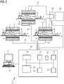
- FIG 2 shows a simplified system 12 for medical data/image acquisition according to an embodiment of the invention.
- This system 12 comprises components as already described above.
- the system comprises three scanners 2 and a number of infrastructure units for the operation of the scanners 2.
- the control device 13 comprises an additional scheduling unit 23 and is configured as a performance scheduling device 13a together with a power unit 20 it is used as common infrastructure unit.
- the performance scheduling device 13a is designed such that it drives all three scanners 2 and the system is designed such that the power unit is able to apply a basic magnetic field to two scanners 2 (the third scanner may have its own power supply that is not shown).
- the power unit is not hardwired to the magnets of the scanners.
- the interlinkage means 21 (power lines) from the scanners 2 are able to be connected to the power unit 20 via a switch unit 22 designed to connect and disconnect a number of scanners to/from the common infrastructure unit by connecting or disconnecting interlinkage means.
- the upper scanner 2 is connected with the power unit, while the right scanner 2 is disconnected.
- the switch unit 22 can connect the right scanner 2 (or disconnect the upper scanner 2) when a common operation schedule dictates that. For this reason the switch unit has a data connection to the performance scheduling device 13a for control.
- the upper scanner 2 is designed as superconducting scanner 2, having its own cooling device 24 as (individual) infrastructure unit.
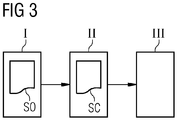
- FIG 3 shows a block diagram of the process flow of a preferred method according to the invention e.g. for controlling a system 12 as shown in FIG 2 .
- a system as shown in FIG 2 with three scanners is regarded, however, the number "three" can also be read as "two or more”.
- step I operation schedules SO for the three scanners 2 are determined (e.g. from data stored in the memory 19) or provided (e.g. from a user).
- This operation schedules SO are the three schedules for the operation of each of the three scanners 2 and provide information when which examination procedures are applied in the next (or at least a following) time period.
- a combined operation schedule SC is determined from the operation schedules SO of the three scanners 2.
- the combined operation schedule SC is e.g. determined in that it is first determined based on the operation schedules SO of the scanners when the scanners are used at the same time and, whether the combined performance of the scanners exceeds the technical properties of a respective common infrastructure unit at a certain period of time. Then the combined operation schedule SC can be arranged such that during combined performance two or all three scanners are driven by one single infrastructure unit, e.g. a power unit for the basic magnetic field and/or a cooling unit or even a gradient unit during a synchronized measuring procedure of the scanners.
- the combined operation schedule can also shift the schedule of a scanner to times where the load is low so that no peaks occur that exceed the technical properties of a respective common infrastructure unit.
- the need of a system for a specific infrastructure medium could be estimated with a iterative procedure.
- the system is provided with a proportional scale of infrastructure units to the number of scanners.
- every scanner has its own infrastructure units.
- the maximum need of the infrastructure media is determined.
- the number of infrastructure units in respect to an infrastructure medium is reduced subsequently until the maximum need of the respective infrastructure medium is just assured.
- the supply of the respective infrastructure medium is covered by a smaller number of respective infrastructure units than in the first time period (at least depending from the maximum need).
- step III the three scanners are driven combined with the common infrastructure unit at least temporally, according to the determined combined operation schedule SO.
- the scanners could be driven in a synchronized measurement procedure by a number of common infrastructure units, preferably wherein measurement protocols are scheduled that are similar in regard to the respective infrastructure medium or the time course of the change of the infrastructure medium.
Abstract
Description
- The invention describes a system for medical data acquisition, especially for medical image acquisition systems, as well as a method to control such system.
- The acquisition of medical data is necessary for modern medicine. Besides "simple" acquisition like measuring temperature or blood pressure, there are more complex data measured with medical examination devices, which are often medical image acquisition devices like e.g. magnetic resonance imaging ("MRI") devices or computer-tomography ("CT") devices. Typically these devices are closed stand-alone devices which are an arrangement of units closely working together.
- for example, a magnetic resonance imaging apparatus includes the actual magnetic resonance scanner in which a patient or test person is positioned on a driven bed. The magnetic resonance scanner is typically equipped with a basic field magnet system, a gradient system as well as an RF transmission antenna system and an RF reception antenna system. At least the basic field magnet system (and especially also the gradient system) typically comprises auxiliary units like cooling units, power units like power amplifiers and sensor units. Furthermore, the MRI apparatus has a central control device that is used to control the MRI apparatus. This central control device typically includes a sequence control unit for measurement sequence control, a radio-frequency transmission device that generates and amplifies RF pulses, a gradient system interface, a radio-frequency reception device and a reconstruction unit that receives the acquired raw data and reconstructs magnetic resonance image data therefrom for the measurements.
- Up to now all MR scanners, but also all other medical examination devices are installed as independent, self-contained units. This is advantageous in the case only one device is used, e.g. in a private doctor's surgery. However, this is a financial and systematic (space, energy and infrastructure) disadvantage in the case a whole "fleet" of, especially similar, examination devices is used as in a hospital, since every single examination device is delivered with all of its components.
- It is the object of the present invention to improve the known devices and methods to facilitate an improvement in medical data acquisition, especially in medical image acquisition.
- This object is achieved by a system according to claim 1, a method according to
claim 7, and a performance scheduling system according toclaim 13. - A system according to the invention for medical data acquisition comprises two or more scanner units and a number of infrastructure units for the operation of the scanner units, wherein the system is designed such that it is able to use an infrastructure unit as a common infrastructure unit for the operation of at least two of the scanner units.
- With "system" there is not meant a common apparatus for medical data acquisition, e.g. one single MRT-apparatus, but a plurality of such devices arranged in connection with another, e.g. as a "fleet" of devices. The invention is especially advantageous in the case there are individual scanner units of the same type, e.g. two or more MRT-devices or two or more CT-devices, since these could be run in a common network allowing a good distribution of resources. However, the scanner units may also be of different types. Although the invention is applicable for all possible data acquisition devices, it is very advantageous for image acquisition devices, since these devices are typically very complex and need a vast number of different (expensive) units to work properly.
- According to the invention it is necessary that the system comprises two or more scanner units. As "scanner units" all units are meant that are able to examine (scan) a patient in order to acquire medical data. In the following scanner units are also designated simply as "scanners". The invention is very advantageous for image-scanners, e.g. MRT-scanners or CT-scanners, since these devices need a vast number of different units to work properly, such as e.g. cooling units, auxiliary systems and power units. Regarding the system according to the invention, one can say that the scanners are bundled into one "multi-scanning facility".
- These different units are designated here and in the following as "infrastructure units", since they provide the infrastructure for a scanner to scan properly. One could say that the infrastructure units deliver the "infrastructure medium" for the scanners. This infrastructure medium does not necessarily have to be a physical fluid, but can be also energy or a data stream. Some exemplary infrastructure units (with the according infrastructure medium in parentheses) are - auxiliary units, such as a cooling unit (cooling medium), a sensor unit (data stream, measurement voltage or measurement current) or a unit providing energy for auxiliary systems (energy),
- power units (energy, electromagnetic waves), preferably a general power supply or a power amplifier, e.g. for RF or gradients in MRI,
- computing units (data stream), preferably an image reconstruction unit or an analysis unit and
- control units (data stream, control voltage or control current), preferably comprising a user interface.
- shielding / insulation units like Faraday cage or acoustic damping insulation
- In contrast to the state of the art, where every device has its own infrastructure units, the system according to the invention is designed such that it is able to use an infrastructure unit as a common infrastructure unit for the operation of at least two of the scanners. This means that it is not necessary in every possible case that a common infrastructure unit (the unit designed to drive two scanners at the same time) is hardwired to two or more scanners (although this also enclosed in the meaning of "able to use"), however it is necessary that the system can connect at least one single infrastructure unit to two or more scanners. Thus, the invention comprises systems where two or more scanners are hardwired to at least one infrastructure unit as well as systems comprising switches to connect an infrastructure unit with two or more scanners.
- It should be noted that an "infrastructure unit" is an infrastructure unit typically included in a common medical examination device and not a power plant nor the power grid of a hospital nor the ethernet of a hospital. One could preferably say that an infrastructure unit is a unit designed to directly be connected with a scanner. one could also say that an infrastructure unit is a unit designed to directly provide a scanner with a respective infrastructure medium.
- It is preferred that the infrastructure medium of the common infrastructure device is no data stream, especially no data stream of acquired data, wherein it is not excluded that such data stream is running in addition to the infrastructure medium in the system. It is preferred that an infrastructure unit provides an infrastructure medium for operating a scanner. Particularly preferred common infrastructure units are units providing a cooling or heating medium and power units.
- The invention is especially advantageous in the course of scanner setups where multiple scan volume instances are provided by design. Just as the BO field generating unit is capable of providing multiple scans simultaneously by sharing the same B0 field, the other infrastructure needs can be shared across the scan places of the system.
- A method according to the invention for controlling a system according to the preceding claims comprises the following steps:
- Providing or determining an operation schedule for the operation of at least two scanner units. The operation schedule is a dataset of operation data of any of the scanners. It comprises information about scheduled operation times and preferably also operation about the need of an infrastructure medium (especially of (all) needed infrastructure media. It could be provided, e.g. as a list, by a user or read from a memory. It could also be determined from operation datasets or datasets provided by medical examining apparatuses or schedules.
- Determining a combined operation schedule of combined operation of the at least two scanner units with a concerted use of a common infrastructure unit based on the schedule for the operation of the at least two scanner units and technical properties of the common infrastructure unit. This does not necessarily involve a operation of the scanners at the same time (however, this aspect is a special advantage of the invention). In every case comprises the combined operation schedule an operation of two scanners by the same common infrastructure unit (at the same time or interleaved).
- Operating the at least two scanner units, especially interleaved or combined with the common infrastructure unit at least temporally, according to the determined combined operation schedule.
- For example, two scanners need cooling and power and the first scanner should run from 9 am to 10:30 am and the second scanner should run from 10 am to 11 am. Then the combined operation schedule could easily schedule the cooling and power for 9 to 11 with a cooling/power connection for both scanners at the scheduled operation times. In the case, the cooling is sufficient for the two scanners, but the technical properties of the power unit are not sufficient to drive both scanners at the same time (wherein a sufficient power output for at least two scanners is actually preferred), then the combined operation schedule could either shift the operation time for the second scanner from 10:30 to 11:30 or each scanner can use its own power unit or at the time from 10 to 10:30 another power unit is aiding the (first) power unit.
- A (managed) performance scheduling device according to the invention for a system according to the invention, is designed to perform a method according to the invention.
- It preferably comprises the following components:
- a data interface design to read and/or determine an operation schedule for the operation of at least two scanner units,
- a determination unit designed for determining a combined operation schedule of combined operation of the at least two scanner units with a concerted use of a common infrastructure unit based on the operation schedule for the operation of the at least two scanner units and technical properties of the common infrastructure unit, and
- an operating unit, designed for operating the at least two scanner units according to the determined combined operation schedule. This operating unit could be a data interface designed to connect to a infrastructure unit, e.g. a control unit of a medical examination apparatus, and sending control data to this infrastructure unit.
- Some units or modules of the system or the performance scheduling device mentioned above can be completely or partially realized as software modules running on a processor of a system or a performance scheduling device. A realization largely in the form of software modules can have the advantage that applications already installed on an existing system can be updated, with relatively little effort, to install and run these units of the present application. The object of the invention is also achieved by a computer program product with a computer program that is directly loadable into the memory of a device of a system or a performance scheduling device (e.g. of a magnetic resonance imaging apparatus), and which comprises program units to perform the steps of the inventive method when the program is executed by the performance scheduling device or the system. In addition to the computer program, such a computer program product can also comprise further parts such as documentation and/or additional components, also hardware components such as a hardware key (dongle etc.) to facilitate access to the software.
- A computer readable medium such as a memory stick, a hard-disk or other transportable or permanently-installed carrier can serve to transport and/or to store the executable parts of the computer program product so that these can be read from a processor unit of a performance scheduling device or a system. A processor unit can comprise one or more microprocessors or their equivalents.
- Particularly advantageous embodiments and features of the invention are given by the dependent claims, as revealed in the following description. Features of different claim categories may be combined as appropriate to give further embodiments not described herein.
- According to a preferred system, an infrastructure unit is a unit selected form the group comprising
- auxiliary units, preferably a cooling unit, a sensor unit or a unit providing energy for auxiliary systems,
- power units, preferably a general power supply or a power amplifier, e.g. for RF or gradients in MRI,
- computing units, preferably an image reconstruction unit or an analysis unit and
- control units, preferably comprising a user interface.
- According to a preferred system, the common infrastructure unit is a computing unit designed as a cloud system, especially wherein the cloud system provides capacity for image reconstruction and/or analysis or provides control information for at least two scanner units. Especially preferred is a local cloud setup where the required performance can be allocated on demand.
- In a preferred system according to the invention, components of the system are part of a data-network, wherein preferably the data-network and scanners (e.g. the magnetic resonance imaging scanners or CT scanners) are in data-communication with each other, wherein the data-network preferably comprises parts of the internet and/or a cloud-based computing system, wherein preferably the system according to the invention or a number of components of this system is realized in or controlled by this cloud-based computing system. For example, components of the system, such as a control device or a data reconstruction unit, could be part of a data-network, wherein preferably the data-network and a scanner that is controlled or which provides the image data are in communication with each other. Such a networked solution could be implemented via an internet platform and/or in a cloud-based computing system.
- The method may also include elements of "cloud computing". In the technical field of "cloud computing", an IT infrastructure is provided over a data-network, e.g. a storage space or processing power and/or application software. The communication between the user and the "cloud" is achieved by means of data interfaces and/or data transmission protocols.
- In the context of "cloud computing", in a preferred embodiment of the method according to the invention, provision of data via a data channel (for example a data-network) to a "cloud" takes place. This "cloud" includes a (remote) computing system, e.g. a computer cluster that typically does not include the user's local machine. This cloud can be made available in particular by the medical facility, which also provides the medical imaging systems. In particular, the image acquisition data is sent to a (remote) computer system (the "cloud") via a RIS (Radiology Information System) or a PACS (Picture Archiving and Communication System).
- Within the scope of a preferred embodiment of the system according to the invention, the abovementioned units (e.g. the control device, the reconstruction unit, the performance scheduling device) Are present on the "cloud" side. A preferred system further comprises, a local computing unit connected to the system via a data channel (e.g. a data-network, particularly configured as RIS or PACS). The local computing unit includes at least one data receiving interface to receive data. Moreover, it is preferred if the local computer additionally has a transmission interface in order to send data to the system.
- A preferred system comprises interlinkage means, preferably power conductors, pipes or data lines, connecting a common infrastructure unit with the scanner units in order to provide the infrastructure medium. A possible infrastructure medium could be energy, cooling medium or data depending on the respective infrastructure unit. Preferably, the system comprises a switch unit designed to connect and disconnect a number of scanner units to/from the common infrastructure unit by connecting or disconnecting interlinkage means. A suitable switch unit could be a controllable electrical switch for power or a controllable valve for a cooling medium. It could also be a router for data.
- A preferred system comprises a scheduling unit designed for managing a dynamic connection of the scanner units to a common infrastructure unit in dependence of the maximum and/or optimum performance of said common infrastructure unit. For example, in the case two scanners demand peak performance simultaneously, the temporal alignment may be adopted in an intelligent way in order to avoid high overall peak demands.
- For example, each measurement may specify the tolerance in the timing for the requested resource, i.e. if in one scan place the RF pulses can be played out interleaved with the RF pulses in another scan place, they can basically share the RF power amplifier.
- The temporal alignment may be performed at various time-scales. For example, complete scan protocols could be played out in an interleaved manner, because between the scan protocols there may be time needed for breathing commands, playing out adjustments or calibration scans etc., so the interleaving may happen on a seconds timescale. As the atomic elements of MR sequences are played out on a micro-seconds raster, the adaptations may also happen on this timescale, e.g. a gradient pulse is delayed by 100 us in order not start after a gradient pulse is finished in a different unit.
- The RF signals could be divided to the scanners via above mentioned switch unit. Preferably, the common infrastructure unit is designed such that it is able to provide a predefined maximum capacity of the respective infrastructure medium (energy, cooling medium, data) required by at least two scanner units.
- According to a preferred system, it is designed such that two or more common infrastructure units can be connected to and disconnected from the same scanner units independently, preferably wherein the system is designed such that a new or additional common infrastructure unit can be additionally connected with scanner units, wherein preferably a common infrastructure unit connected to the scanner units can be disconnected afterwards. This concept enables a continuous renewal of the infrastructure units without any downtimes. For example, first a new unit is added and then the old unit is disconnected.
- According to a preferred method, in order to determine the combined operation schedule, the system is initially provided (in a first iteration, in course of the installation) with a proportional scale of infrastructure units to the number of scanner units and then after a time period, the number of infrastructure units in respect to an infrastructure medium is reduced subsequently if the maximum need of the respective infrastructure medium during the time period is covered by a smaller number of respective infrastructure units. Thus, the system can be equipped with a maximum expected resources overshoot and then determined, if infrastructure units can be withdrawn.
- Assuming an asynchronous demand for resources, the overall system performance may need to cover a peak demand where the effect of averaging out peak demands is subsequently used to reduce the overall resource requirements. After an analyzing phase the resources may be reduced with this preferred method to a level covering all or a defined cut-off of the observed peak demand.
- According to a preferred method, the combined operation schedule is determined based on smart multiplexing and/or interleaving of the usage of infrastructure units for the scanner units. Preferably it is determined, based on the operation schedule of the scanner units, whether the combined performance of the scanner units exceeds the technical properties of the common infrastructure unit at a certain period of time, and in the case of a determined exceedance one of the at least two scanner units are disconnected from the common infrastructure unit and/or another infrastructure unit for the respective infrastructure medium is connected to the scanner units.
- Thus, the schedule of combined operation is preferably designed such that the temporal alignment of common infrastructure units and scanners is adopted in an intelligent way in order to avoid high overall peak demands. For example, each measurement may specify the tolerance in the timing for the requested infrastructure medium, e.g. if in one scan place the RF pulses can be played out interleaved with the RF pulses in another scan place, they can basically share the RF power amplifier.
- According to a preferred method, the scanner units are driven in a synchronized measurement procedure by a number of common infrastructure units, preferably wherein measurement protocols are scheduled that are similar in regard to the respective infrastructure medium or the time course of the change of the infrastructure medium.
- According to a preferred method, the schedule for the operation of at least two scanner units corresponds to a time period longer than a day, especially longer than a month and the determining a schedule of combined operation comprises information about time intervals where the need of the at least two scanner units of the infrastructure medium would exceed the maximum performance of the used common infrastructure unit, wherein a notification for a user is sent or displayed. The notification informs the user that an installation of additional or more powerful respective infrastructure unit will be needed at these time intervals. However, the more intelligence is implemented in the resource scheduling, the less resources are needed overall. Thus, the peak performance can be determined and a suitable number of infrastructure units can be ordered and installed to increase the performance of the system.
- According to a preferred method, the system comprises an additional infrastructure unit in addition to the common infrastructure unit that is similar on behalf of the infrastructure medium, wherein the additional infrastructure unit is connected or designed to be connected to an additional scanner unit of the system. Thus, the relative usage of performance can be allocated asymmetrically, i.e. if for some reason there is a need to use one system with higher performance than the other within a cluster of scan places using the same infrastructure. The distribution of resources can be implemented based on priorities, workflows (i.e. allow for more gradient performance in a diffusion scan etc.).
- Other objects and features of the present invention will become apparent from the following detailed descriptions considered in conjunction with the accompanying drawings. It is to be understood, however, that the drawings are designed solely for the purposes of illustration and not as a definition of the limits of the invention.
-
FIG 1 shows a simplified MRI-apparatus from the state of the art. -
FIG 2 shows a simplified system according to an embodiment of the invention. -
FIG 3 shows a block diagram of the process flow of a preferred method according to the invention. - In the diagrams, like numbers refer to like objects throughout. Objects in the diagrams are not necessarily drawn to scale.
-
FIG 1 shows a schematic representation of a magnetic resonance imaging apparatus 1 ("MRI-apparatus"). The MRI apparatus 1 includes the actual magnetic resonance scanner (data acquisition unit) 2 with anexamination space 3 or patient tunnel in which a patient or test person is positioned on a drivenbed 8, in whose body the actual examination object is located. - The
magnetic resonance scanner 2 is typically equipped with a basicfield magnet system 4, agradient system 6 as well as an RFtransmission antenna system 5 and an RFreception antenna system 7. In the shown exemplary embodiment, the RFtransmission antenna system 5 is a whole-body coil permanently installed in themagnetic resonance scanner 2, in contrast to which the RFreception antenna system 7 is formed as local coils (symbolized here by only a single local coil) to be arranged on the patient or test subject. In principle, however, the whole-body coil can also be used as an RF reception antenna system, and the local coils can respectively be switched into different operating modes. - The basic
field magnet system 4 is designed in a typical manner so that it generates a basic magnetic field in the longitudinal direction of the patient, i.e. along the longitudinal axis of themagnetic resonance scanner 2 that proceeds in the z-direction. Thegradient system 6 typically includes individually controllable gradient coils in order to be able to switch (activate) gradients in the x-direction, y-direction or z-direction independently of one another. - The MRI apparatus 1 shown here is a whole-body apparatus with a patient tunnel into which a patient can be completely introduced. However, in principle the invention can also be used at other MRI apparatuses, for example with a laterally open, C-shaped housing, as well as in smaller magnetic resonance scanners in which only one body part can be positioned.
- Furthermore, the MRI apparatus 1 has a
central control device 13 that is used to control the MRI apparatus 1. Thiscentral control device 13 includes asequence control unit 14 for measurement sequence control. With thissequence control unit 14, the series of radio-frequency pulses (RF pulses) and gradient pulses can be controlled depending on a selected pulse sequence. - To output the individual RF pulses of an pulse sequence, the
central control device 13 has a radio-frequency transmission device 15 that generates and amplifies the RF pulses and feeds them into the RFtransmission antenna system 5 via a suitable interface (not shown in detail). To control the gradient coils of thegradient system 6, thecontrol device 13 has agradient system interface 16. Thesequence control unit 14 communicates in a suitable manner with the radio-frequency transmission device 15 and thegradient system interface 16 to emit the pulse sequence. - Moreover, the
control device 13 has a radio-frequency reception device 17 (likewise communicating with thesequence control unit 14 in a suitable manner) in order to acquire magnetic resonance signals (i.e. raw data) for the individual measurements, which magnetic resonance signals are received in a coordinated manner from the RFreception antenna system 7 within the scope of the pulse sequence. - A
reconstruction unit 18 receives the acquired raw data and reconstructs magnetic resonance image data therefrom for the measurements. This reconstruction is typically performed on the basis of parameters that may be specified in the respective measurement or control protocol. For example, the image data can then be stored in amemory 19. - Operation of the
central control device 13 can take place via a terminal 10 with an input unit and adisplay unit 9, via which the entire MRI apparatus 1 can thus also be operated by an operator. MR images can also be displayed at thedisplay unit 9, and measurements can be planned and started by means of the input unit (possibly in combination with the display unit 9), and in particular suitable control protocols can be selected (and possibly modified) with suitable series of pulse sequence PS as explained above. - The MRI apparatus 1 according to the invention, and in particular the
control device 13, can have a number of additional components that are not shown in detail but are typically present at such apparatuses, for example a network interface in order to connect the entire apparatus with a network and be able to exchange raw data and/or image data or, respectively, parameter maps, but also additional data (for example patient-relevant data or control protocols). - All systems, devices and units described here that have a function in the MRT-apparatus (and are not the scanner) may be regarded as infrastructure units. Thus, infrastructure units are here the
central control device 13, thesequence control unit 14, the radio-frequency transmission device 15, thegradient system interface 16, the radio-frequency reception device 17, thereconstruction unit 18 and thememory 19. Additional infrastructure units (not shown here) are power units, cooling units, sensor units and units driving auxiliary systems. -
FIG 2 shows asimplified system 12 for medical data/image acquisition according to an embodiment of the invention. Thissystem 12 comprises components as already described above. In contrast to the MRI-apparatus 1 the system comprises threescanners 2 and a number of infrastructure units for the operation of thescanners 2. In this example, thecontrol device 13 comprises anadditional scheduling unit 23 and is configured as aperformance scheduling device 13a together with apower unit 20 it is used as common infrastructure unit. Theperformance scheduling device 13a is designed such that it drives all threescanners 2 and the system is designed such that the power unit is able to apply a basic magnetic field to two scanners 2 (the third scanner may have its own power supply that is not shown). - In contrast to the
performance scheduling device 13a that is in this example hardwired to the threescanner units 2 via interlinkage means 21 (here data lines and/or power lines), the power unit is not hardwired to the magnets of the scanners. The interlinkage means 21 (power lines) from thescanners 2 are able to be connected to thepower unit 20 via aswitch unit 22 designed to connect and disconnect a number of scanners to/from the common infrastructure unit by connecting or disconnecting interlinkage means. In the shown example, theupper scanner 2 is connected with the power unit, while theright scanner 2 is disconnected. However, theswitch unit 22 can connect the right scanner 2 (or disconnect the upper scanner 2) when a common operation schedule dictates that. For this reason the switch unit has a data connection to theperformance scheduling device 13a for control. - In this example, the
upper scanner 2 is designed assuperconducting scanner 2, having itsown cooling device 24 as (individual) infrastructure unit. -
FIG 3 shows a block diagram of the process flow of a preferred method according to the invention e.g. for controlling asystem 12 as shown inFIG 2 . In the following a system as shown inFIG 2 with three scanners is regarded, however, the number "three" can also be read as "two or more". - In step I, operation schedules SO for the three
scanners 2 are determined (e.g. from data stored in the memory 19) or provided (e.g. from a user). This operation schedules SO are the three schedules for the operation of each of the threescanners 2 and provide information when which examination procedures are applied in the next (or at least a following) time period. - In step II, a combined operation schedule SC is determined from the operation schedules SO of the three
scanners 2. the combined operation schedule SC is e.g. determined in that it is first determined based on the operation schedules SO of the scanners when the scanners are used at the same time and, whether the combined performance of the scanners exceeds the technical properties of a respective common infrastructure unit at a certain period of time. Then the combined operation schedule SC can be arranged such that during combined performance two or all three scanners are driven by one single infrastructure unit, e.g. a power unit for the basic magnetic field and/or a cooling unit or even a gradient unit during a synchronized measuring procedure of the scanners. - In a time period when the combined performance of the scanners exceeds the technical properties of a respective common infrastructure unit, one or two scanners are de-coupled from the respective infrastructure unit and coupled to another infrastructure unit. It is also possible that another common infrastructure unit is added to aid the first common infrastructure unit. Although peak performance could result in the costs for an additional infrastructure unit, these costs are not necessary in any case. The combined operation schedule can also shift the schedule of a scanner to times where the load is low so that no peaks occur that exceed the technical properties of a respective common infrastructure unit.
- To achieve this, the need of a system for a specific infrastructure medium could be estimated with a iterative procedure. In a first time period, the system is provided with a proportional scale of infrastructure units to the number of scanners. Thus, in the first time period every scanner has its own infrastructure units. In the first time period, the maximum need of the infrastructure media is determined.
- Then, after the first time period, the number of infrastructure units in respect to an infrastructure medium is reduced subsequently until the maximum need of the respective infrastructure medium is just assured. Thus, the supply of the respective infrastructure medium is covered by a smaller number of respective infrastructure units than in the first time period (at least depending from the maximum need).
- In step III, the three scanners are driven combined with the common infrastructure unit at least temporally, according to the determined combined operation schedule SO. Regarding infrastructure units that have a direct effect on the measurement (e.g. gradient power supply in contrast to cooling), the scanners could be driven in a synchronized measurement procedure by a number of common infrastructure units, preferably wherein measurement protocols are scheduled that are similar in regard to the respective infrastructure medium or the time course of the change of the infrastructure medium.
- Although the present invention has been disclosed in the form of preferred embodiments and variations thereon, it will be understood that numerous additional modifications and variations could be made thereto without departing from the scope of the invention. For the sake of clarity, it is to be understood that the use of "a" or "an" throughout this application does not exclude a plurality, and "comprising" does not exclude other steps or elements. The mention of a "unit" or a "device" does not preclude the use of more than one unit or device.
Claims (15)
- A system (12) for medical data acquisition comprising two or more scanner units (2) and a number of infrastructure units (13a, 20, 24) for the operation of the scanner units (2), wherein the system (12) is designed such that it is able to use an infrastructure unit (13a, 20, 24) as a common infrastructure unit (13a, 20) for the operation of at least two of the scanner units (2).
- The system according to claim 1, wherein an infrastructure unit (13a, 20, 24) is a unit selected from the group comprising- auxiliary units, preferably a cooling unit (24), a sensor unit or a unit providing energy for auxiliary systems,- power units (20), preferably a general power supply or a power amplifier,- computing units, preferably an image reconstruction unit or an analysis unit and- control units (13, 13a), preferably comprising a user interface.- shielding or insulation units.
- The system according to one of the preceding claims, wherein the common infrastructure unit (13a, 20) is a computing unit designed as a cloud system, especially wherein the cloud system provides capacity for image reconstruction and/or analysis or provides control information for at least two scanner units (2).
- The system according to one of the preceding claims, comprising interlinkage means (21), preferably power conductors, pipes or data lines, connecting a common infrastructure unit (13a, 20) with the scanner units (2) in order to provide the infrastructure medium preferably wherein the system (12) comprises a switch unit (22) designed to connect and disconnect a number of scanner units (2) to/from the common infrastructure unit (13a, 20) by connecting or disconnecting interlinkage means (21).
- The system according to one of the preceding claims, comprising a scheduling unit (23) designed for managing a dynamic connection of the scanner units (20) to a common infrastructure unit (13a, 20) in dependence of the maximum and/or optimum performance of said common infrastructure unit (13a, 20),
preferably wherein the common infrastructure unit (13a, 20) is designed such that it is able to provide a predefined maximum capacity of the respective infrastructure medium required by at least two scanner units (2). - The system according to one of the preceding claims, designed such that two or more common infrastructure units (13a, 20) can be connected to and disconnected from the same scanner units (20) independently,
preferably wherein the system (12) is designed such that a new or additional common infrastructure unit (13a, 20) can be additionally connected with scanner units (2),
wherein preferably a common infrastructure unit (13a, 20) connected to the scanner units (2) can be disconnected afterwards. - A method for controlling a system (12) according to the preceding claims comprising the steps:- providing or determining an operation schedule (SO) for the operation of at least two scanner units (2),- determining a combined operation schedule (SC) of combined operation of the at least two scanner units (2) with a concerted use of a common infrastructure unit (13a, 20) based on the operation schedule for the operation of the at least two scanner units (2) and technical properties of the common infrastructure unit (13a, 20),- operating the at least two scanner units (2) according to the determined combined operation schedule (SC).
- The method according to claim 7, wherein in order to determine the combined operation schedule (SC), the system (12) is initially provided with a proportional scale of infrastructure units (13a, 20, 24) to the number of scanner units (2) and then after a time period, the number of infrastructure units (13a, 20, 24) in respect to an infrastructure medium is reduced subsequently if the maximum need of the respective infrastructure medium during the time period is covered by a smaller number of respective infrastructure units (13a, 20, 24).
- The method according to claim 7 or 8, wherein the combined operation schedule (SC) is determined based on smart multiplexing and/or interleaving of the usage of infrastructure units (13a, 20, 24) for the scanner units (2),
preferably wherein it is determined, based on the operation schedule (SO) of the scanner units (2), whether the combined performance of the scanner units (2) exceeds the technical properties of the common infrastructure unit (13a, 20) at a certain period of time, and in the case of a determined exceedance one of the at least two scanner units (2) are disconnected from the common infrastructure unit (13a, 20) and/or another infrastructure unit (13a, 20) for the respective infrastructure medium is connected to the scanner units (2) . - The method according to one of claims 7 to 9, wherein the scanner units (2) are driven in a synchronized measurement procedure by a number of common infrastructure units (13a, 20), preferably wherein measurement protocols are scheduled that are similar in regard to the respective infrastructure medium or the time course of the change of the infrastructure medium.
- The method according to one of claims 7 to 10, wherein the operation schedule (SO) of at least two scanner units (2) corresponds to a time period longer than a day, especially longer than a month and the determining a combined operation schedule (SC) comprises information about time intervals where the need of the at least two scanner units (2) of the infrastructure medium would exceed the maximum performance of the used common infrastructure unit (13a, 20), wherein a notification for a user is sent or displayed.
- The method according to one of claims 7 to 10, wherein the system (12) comprises an additional infrastructure unit (13a, 20) in addition to the common infrastructure unit (13a, 20) that is similar on behalf of the infrastructure medium, wherein the additional infrastructure unit (13a, 20) is connected or designed to be connected to an additional scanner unit (2) of the system (12).
- A performance scheduling device (13a) for a system (12) according to one of claims 1 to 6, designed to perform a method according to one of claims 7 to 12.
- A computer program product comprising a computer program that is directly loadable into a memory of a control unit of a control device or analyzation device and which comprises program elements for performing steps of the method according to any of claims 7 to 12 when the computer program is executed by the control device or analyzation device.
- A computer-readable medium on which is stored program elements that can be read and executed by a computer unit in order to perform steps of the method according to any of claims 7 to 12 when the program elements are executed by the computer unit.
Priority Applications (3)
| Application Number | Priority Date | Filing Date | Title |
|---|---|---|---|
| EP19211886.7A EP3828577A1 (en) | 2019-11-27 | 2019-11-27 | System for medical data acquisition with two scanner units sharing a common infrastructure unit |
| US17/105,270 US11660017B2 (en) | 2019-11-27 | 2020-11-25 | Medical data acquisition |
| CN202011342338.7A CN112863646B (en) | 2019-11-27 | 2020-11-25 | System for medical data acquisition |
Applications Claiming Priority (1)
| Application Number | Priority Date | Filing Date | Title |
|---|---|---|---|
| EP19211886.7A EP3828577A1 (en) | 2019-11-27 | 2019-11-27 | System for medical data acquisition with two scanner units sharing a common infrastructure unit |
Publications (1)
| Publication Number | Publication Date |
|---|---|
| EP3828577A1 true EP3828577A1 (en) | 2021-06-02 |
Family
ID=68731697
Family Applications (1)
| Application Number | Title | Priority Date | Filing Date |
|---|---|---|---|
| EP19211886.7A Pending EP3828577A1 (en) | 2019-11-27 | 2019-11-27 | System for medical data acquisition with two scanner units sharing a common infrastructure unit |
Country Status (3)
| Country | Link |
|---|---|
| US (1) | US11660017B2 (en) |
| EP (1) | EP3828577A1 (en) |
| CN (1) | CN112863646B (en) |
Citations (8)
| Publication number | Priority date | Publication date | Assignee | Title |
|---|---|---|---|---|
| US4668915A (en) * | 1985-03-15 | 1987-05-26 | Honda Giken Kogyo Kabushiki Kaisha | Non-uniform field magnetic resonance dual patient imaging system |
| US20030181804A1 (en) * | 2002-03-20 | 2003-09-25 | Koninklijke Philips Electronics N.V. | Distributed diagnostic imaging systems |
| US20060101836A1 (en) * | 2002-08-20 | 2006-05-18 | Hidekazu Tanaka | Very low temperature refrigerator |
| US20110081065A1 (en) * | 2009-10-01 | 2011-04-07 | Christian Canstein | Centralized image reconstruction for tomographic imaging techniques in medical engineering |
| US20110166440A1 (en) * | 2008-09-26 | 2011-07-07 | Koninklijke Philips Electronics N.V. | Diagnostic imaging system and method |
| US20140278496A1 (en) * | 2013-03-14 | 2014-09-18 | Volcano Corporation | System and Method for Medical Resource Scheduling |
| WO2015047273A1 (en) * | 2013-09-26 | 2015-04-02 | Hewlett-Packard Development Company, L.P. | Controlling usage of resources based on operating status and communications |
| US20150153428A1 (en) * | 2013-11-29 | 2015-06-04 | Ping Chen | Cooling Device and Method for Magnetic Resonance Imaging System |
Family Cites Families (55)
| Publication number | Priority date | Publication date | Assignee | Title |
|---|---|---|---|---|
| US6501849B1 (en) * | 1997-09-02 | 2002-12-31 | General Electric Company | System and method for performing image-based diagnosis over a network |
| US6501818B1 (en) * | 1997-11-26 | 2002-12-31 | Ge Medical Systems Global Technology Company, Llc | Apparatus and methods for displaying computed tomography fluoroscopy images including data transfer provided over a network |
| US6609217B1 (en) * | 1998-03-30 | 2003-08-19 | General Electric Company | System and method for diagnosing and validating a machine over a network using waveform data |
| US6298112B1 (en) * | 1998-07-01 | 2001-10-02 | Ge Medical Systems Global Technology Co. Llc | Methods and apparatus for helical multi-frame image reconstruction in a computed tomography fluoro system including data communications over a network |
| US6404909B2 (en) * | 1998-07-16 | 2002-06-11 | General Electric Company | Method and apparatus for processing partial lines of scanned images |
| US6198283B1 (en) * | 1998-09-18 | 2001-03-06 | Ge Medical Systems Global Technology Llc | System and method of phase sensitive MRI reconstruction using partial k-space data and including a network |
| US6578002B1 (en) * | 1998-11-25 | 2003-06-10 | Gregory John Derzay | Medical diagnostic system service platform |
| US6381557B1 (en) * | 1998-11-25 | 2002-04-30 | Ge Medical Systems Global Technology Company, Llc | Medical imaging system service evaluation method and apparatus |
| US6166544A (en) * | 1998-11-25 | 2000-12-26 | General Electric Company | MR imaging system with interactive image contrast control |
| US6377162B1 (en) * | 1998-11-25 | 2002-04-23 | Ge Medical Systems Global Technology Company, Llc | Medical diagnostic field service method and apparatus |
| US6434572B2 (en) * | 1998-11-25 | 2002-08-13 | Ge Medical Technology Services, Inc. | Medical diagnostic system management method and apparatus |
| US6598011B1 (en) * | 1998-11-25 | 2003-07-22 | Ianne Mae Howards Koritzinsky | Medical diagnostic system services interface |
| US6396266B1 (en) * | 1998-11-25 | 2002-05-28 | General Electric Company | MR imaging system with interactive MR geometry prescription control |
| US7127499B1 (en) * | 1998-11-25 | 2006-10-24 | General Electric Company | Medical diagnostic system service method and apparatus |
| US6353445B1 (en) * | 1998-11-25 | 2002-03-05 | Ge Medical Systems Global Technology Company, Llc | Medical imaging system with integrated service interface |
| US6272469B1 (en) * | 1998-11-25 | 2001-08-07 | Ge Medical Systems Global Technology Company, Llc | Imaging system protocol handling method and apparatus |
| US6351122B1 (en) * | 1998-12-22 | 2002-02-26 | General Electric Company | MRI reconstruction using scan-specific partial echo and partial NEX data acquisitions and a network |
| US6483933B1 (en) * | 1998-12-30 | 2002-11-19 | Ge Medical Systems Global Technology Company, Llc | Digital-to-film radiographic image conversion including a network |
| US7080095B2 (en) * | 1998-12-31 | 2006-07-18 | General Electric Company | Medical diagnostic system remote service method and apparatus |
| US6126605A (en) * | 1998-12-31 | 2000-10-03 | General Electric Company | Ultrasound color flow display optimization by adjusting dynamic range |
| US6256372B1 (en) * | 1999-03-16 | 2001-07-03 | General Electric Company | Apparatus and methods for stereo radiography |
| US6077226A (en) * | 1999-03-30 | 2000-06-20 | General Electric Company | Method and apparatus for positioning region of interest in image |
| US6370217B1 (en) * | 1999-05-07 | 2002-04-09 | General Electric Company | Volumetric computed tomography system for cardiac imaging |
| US6494831B1 (en) * | 1999-09-03 | 2002-12-17 | Ge Medical Technology Services, Inc. | Medical diagnostic system service connectivity method and apparatus |
| US6691134B1 (en) * | 1999-11-24 | 2004-02-10 | Ge Medical Technology Services, Inc. | Image-based artifact troubleshooting for medical systems |
| US6509914B1 (en) * | 1999-11-24 | 2003-01-21 | Ge Medical Technology Services, Inc. | Problem-solution resource system for medical diagnostic equipment |
| US6325540B1 (en) * | 1999-11-29 | 2001-12-04 | General Electric Company | Method and apparatus for remotely configuring and servicing a field replaceable unit in a medical diagnostic system |
| US6574518B1 (en) * | 1999-11-29 | 2003-06-03 | General Electric Company | Method and apparatus for communicating operational data for a system unit in a medical diagnostic system |
| US6412980B1 (en) * | 1999-12-30 | 2002-07-02 | Ge Medical Systems Global Technology Company, Llc | Method and apparatus for configuring and monitoring a system unit in a medical diagnostic system |
| US7263710B1 (en) * | 1999-12-31 | 2007-08-28 | General Electric Company | Medical diagnostic system with on-line real-time video training |
| US6546230B1 (en) * | 1999-12-31 | 2003-04-08 | General Electric Company | Method and apparatus for skills assessment and online training |
| US6581069B1 (en) * | 2000-06-01 | 2003-06-17 | Ge Medical Technology Services, Inc. | Automated activation and deactivation of operational data logging on medical imaging device |
| US20040260790A1 (en) * | 2000-12-21 | 2004-12-23 | Ge Medical System Global Technology Company, Llc | Method and apparatus for remote or collaborative control of an imaging system |
| US7774211B1 (en) * | 2001-04-13 | 2010-08-10 | General Electric Company | Method and system for graphically displaying consolidated condition data for equipment in a host facility |
| WO2004053519A1 (en) * | 2002-12-09 | 2004-06-24 | Koninklijke Philips Electronics N.V. | Distributed medical imaging system |
| US20070124169A1 (en) * | 2005-11-30 | 2007-05-31 | Irving Russell R | Networked system of thin client diagnostic imaging scanners |
| WO2011058458A1 (en) * | 2009-11-13 | 2011-05-19 | Koninklijke Philips Electronics, N.V. | Quick re-connect diversity radio system |
| US8896439B2 (en) * | 2009-11-25 | 2014-11-25 | Consensys Imaging Service, Inc. | Remote maintenance of medical imaging devices |
| CA2718696C (en) * | 2010-06-08 | 2018-06-12 | Merge Healthcare, Inc. | Remote control of medical devices using instant messaging infrastructure |
| US8972748B2 (en) * | 2011-05-13 | 2015-03-03 | General Electric Company | System and method for multi-tasking of a medical imaging system |
| US9235889B1 (en) * | 2012-06-11 | 2016-01-12 | University Of Central Florida Research Foundation, Inc. | Systems, apparatus and methods for collecting and storing raw scan data and software for performing data processing, image reconstruction and interpretation |
| US9436799B2 (en) * | 2012-07-30 | 2016-09-06 | General Electric Company | Systems and methods for remote image reconstruction |
| WO2014091374A2 (en) * | 2012-12-12 | 2014-06-19 | Koninklijke Philips N.V. | Motion detection and correction method for magnetic resonance diffusion weighted imaging (dwi) |
| US10445465B2 (en) * | 2013-11-19 | 2019-10-15 | General Electric Company | System and method for efficient transmission of patient data |
| WO2016135120A1 (en) * | 2015-02-24 | 2016-09-01 | Koninklijke Philips N.V. | Scan geometry planning method for mri or ct |
| WO2016201573A1 (en) * | 2015-06-16 | 2016-12-22 | Quantum Dental Technologies Inc. | System and method of monitoring consumable use based on correlations with diagnostic testing |
| DE102015220107A1 (en) * | 2015-10-15 | 2017-04-20 | Siemens Healthcare Gmbh | Method for calculating a CT scanner protocol |
| US10561320B2 (en) * | 2015-12-21 | 2020-02-18 | Zoll Medical Corporation | Time synchronization in a medical device system or network |
| CN109074866A (en) * | 2016-04-04 | 2018-12-21 | 皇家飞利浦有限公司 | Medical image system managing device |
| WO2017174379A1 (en) * | 2016-04-04 | 2017-10-12 | Koninklijke Philips N.V. | A remote medical imaging system management arrangement |
| EP3388854B1 (en) * | 2017-04-11 | 2020-09-16 | Siemens Healthcare GmbH | Standardized wireless coupling between a magnetic resonance system and an external device |
| WO2019140155A1 (en) * | 2018-01-12 | 2019-07-18 | Kineticor, Inc. | Systems, devices, and methods for tracking and/or analyzing subject images and/or videos |
| US10859645B2 (en) * | 2018-05-31 | 2020-12-08 | General Electric Company | Method and systems for coil selection in magnetic resonance imaging |
| US11651850B2 (en) * | 2019-12-20 | 2023-05-16 | The Regents Of The University Of Michigan | Computer vision technologies for rapid detection |
| DE102020213920A1 (en) * | 2020-11-05 | 2022-05-05 | Siemens Healthcare Gmbh | MR scanner control |
-
2019
- 2019-11-27 EP EP19211886.7A patent/EP3828577A1/en active Pending
-
2020
- 2020-11-25 US US17/105,270 patent/US11660017B2/en active Active
- 2020-11-25 CN CN202011342338.7A patent/CN112863646B/en active Active
Patent Citations (8)
| Publication number | Priority date | Publication date | Assignee | Title |
|---|---|---|---|---|
| US4668915A (en) * | 1985-03-15 | 1987-05-26 | Honda Giken Kogyo Kabushiki Kaisha | Non-uniform field magnetic resonance dual patient imaging system |
| US20030181804A1 (en) * | 2002-03-20 | 2003-09-25 | Koninklijke Philips Electronics N.V. | Distributed diagnostic imaging systems |
| US20060101836A1 (en) * | 2002-08-20 | 2006-05-18 | Hidekazu Tanaka | Very low temperature refrigerator |
| US20110166440A1 (en) * | 2008-09-26 | 2011-07-07 | Koninklijke Philips Electronics N.V. | Diagnostic imaging system and method |
| US20110081065A1 (en) * | 2009-10-01 | 2011-04-07 | Christian Canstein | Centralized image reconstruction for tomographic imaging techniques in medical engineering |
| US20140278496A1 (en) * | 2013-03-14 | 2014-09-18 | Volcano Corporation | System and Method for Medical Resource Scheduling |
| WO2015047273A1 (en) * | 2013-09-26 | 2015-04-02 | Hewlett-Packard Development Company, L.P. | Controlling usage of resources based on operating status and communications |
| US20150153428A1 (en) * | 2013-11-29 | 2015-06-04 | Ping Chen | Cooling Device and Method for Magnetic Resonance Imaging System |
Also Published As
| Publication number | Publication date |
|---|---|
| US11660017B2 (en) | 2023-05-30 |
| CN112863646A (en) | 2021-05-28 |
| US20210153766A1 (en) | 2021-05-27 |
| CN112863646B (en) | 2024-03-22 |
Similar Documents
| Publication | Publication Date | Title |
|---|---|---|
| US20210109174A1 (en) | Low-field diffusion weighted imaging | |
| JP6761416B2 (en) | Automatic configuration of low magnetic field magnetic resonance imaging system | |
| US20200337587A1 (en) | Techniques for dynamic control of a magnetic resonance imaging system | |
| CN103027679B (en) | For controlling the method for magnetic resonance system | |
| RU2633283C2 (en) | System of magnetic resonance examination with preferred settings based on intellectual data analysis | |
| US10241175B2 (en) | Medical imaging apparatus having multiple subsystems, and operating method therefor | |
| CN104379059A (en) | Scan protocol adjusting apparatus, imaging apparatus, and method for adjusting scan protocol | |
| US20190011518A1 (en) | Method and apparatus for optimization of a time progression of a magnetic resonance control sequence | |
| US20120089011A1 (en) | Method and apparatus for scanning control and displaying images in a magnetic resonance scanning chamber | |
| JP2019195588A (en) | Magnetic resonance imaging apparatus and multi-slice imaging method | |
| US11660017B2 (en) | Medical data acquisition | |
| US10288709B2 (en) | Medical imaging examination apparatus having multiple sub-systems and method for the operation thereof | |
| US20190310332A1 (en) | Magnetic field gradient coil assembly with integrated modulator and switch unit | |
| KR20160038794A (en) | Determining time windows in a scan sequence | |
| JP2012223255A (en) | Medical image display device | |
| JP2012139343A (en) | Magnetic resonance imaging apparatus, medical image server, and medical image reference device | |
| US20160282435A1 (en) | Magnetic resonance imaging apparatus | |
| JP2011200409A (en) | Magnetic resonance imaging device | |
| EP3440576A1 (en) | A medical imaging system management arrangement | |
| WO2018221831A1 (en) | Method of generating magnetic resonance image and magnetic resonance imaging apparatus therefor | |
| JP2014076137A (en) | Medical image diagnostic device and image processing management device | |
| KR20130111445A (en) | Control of a magnetic resonance system | |
| Padarthi et al. | Affordable, state‐of‐the‐art, magnetic resonance imaging scanners: Design and manufacturing insights | |
| US8218842B2 (en) | Magnetic resonance imaging apparatus, image processing apparatus, and image processing method | |
| WO2018221832A1 (en) | Method of generating magnetic resonance image and magnetic resonance imaging apparatus therefor |
Legal Events
| Date | Code | Title | Description |
|---|---|---|---|
| PUAI | Public reference made under article 153(3) epc to a published international application that has entered the european phase |
Free format text: ORIGINAL CODE: 0009012 |
|
| STAA | Information on the status of an ep patent application or granted ep patent |
Free format text: STATUS: THE APPLICATION HAS BEEN PUBLISHED |
|
| AK | Designated contracting states |
Kind code of ref document: A1 Designated state(s): AL AT BE BG CH CY CZ DE DK EE ES FI FR GB GR HR HU IE IS IT LI LT LU LV MC MK MT NL NO PL PT RO RS SE SI SK SM TR |
|
| STAA | Information on the status of an ep patent application or granted ep patent |
Free format text: STATUS: REQUEST FOR EXAMINATION WAS MADE |
|
| 17P | Request for examination filed |
Effective date: 20211130 |
|
| RBV | Designated contracting states (corrected) |
Designated state(s): AL AT BE BG CH CY CZ DE DK EE ES FI FR GB GR HR HU IE IS IT LI LT LU LV MC MK MT NL NO PL PT RO RS SE SI SK SM TR |
|
| RAP1 | Party data changed (applicant data changed or rights of an application transferred) |
Owner name: SIEMENS HEALTHINEERS AG |