EP3828428A1 - Dispositif de liaison comprenant une chape boulonnée et une bague déformable dans la chape - Google Patents
Dispositif de liaison comprenant une chape boulonnée et une bague déformable dans la chape Download PDFInfo
- Publication number
- EP3828428A1 EP3828428A1 EP20209194.8A EP20209194A EP3828428A1 EP 3828428 A1 EP3828428 A1 EP 3828428A1 EP 20209194 A EP20209194 A EP 20209194A EP 3828428 A1 EP3828428 A1 EP 3828428A1
- Authority
- EP
- European Patent Office
- Prior art keywords
- ring
- cheeks
- bore
- bolt
- assembly according
- Prior art date
- Legal status (The legal status is an assumption and is not a legal conclusion. Google has not performed a legal analysis and makes no representation as to the accuracy of the status listed.)
- Granted
Links
Images


Classifications
-
- F—MECHANICAL ENGINEERING; LIGHTING; HEATING; WEAPONS; BLASTING
- F16—ENGINEERING ELEMENTS AND UNITS; GENERAL MEASURES FOR PRODUCING AND MAINTAINING EFFECTIVE FUNCTIONING OF MACHINES OR INSTALLATIONS; THERMAL INSULATION IN GENERAL
- F16C—SHAFTS; FLEXIBLE SHAFTS; ELEMENTS OR CRANKSHAFT MECHANISMS; ROTARY BODIES OTHER THAN GEARING ELEMENTS; BEARINGS
- F16C11/00—Pivots; Pivotal connections
- F16C11/04—Pivotal connections
-
- F—MECHANICAL ENGINEERING; LIGHTING; HEATING; WEAPONS; BLASTING
- F16—ENGINEERING ELEMENTS AND UNITS; GENERAL MEASURES FOR PRODUCING AND MAINTAINING EFFECTIVE FUNCTIONING OF MACHINES OR INSTALLATIONS; THERMAL INSULATION IN GENERAL
- F16C—SHAFTS; FLEXIBLE SHAFTS; ELEMENTS OR CRANKSHAFT MECHANISMS; ROTARY BODIES OTHER THAN GEARING ELEMENTS; BEARINGS
- F16C11/00—Pivots; Pivotal connections
- F16C11/04—Pivotal connections
- F16C11/045—Pivotal connections with at least a pair of arms pivoting relatively to at least one other arm, all arms being mounted on one pin
-
- B—PERFORMING OPERATIONS; TRANSPORTING
- B64—AIRCRAFT; AVIATION; COSMONAUTICS
- B64C—AEROPLANES; HELICOPTERS
- B64C1/00—Fuselages; Constructional features common to fuselages, wings, stabilising surfaces or the like
- B64C1/06—Frames; Stringers; Longerons ; Fuselage sections
-
- B—PERFORMING OPERATIONS; TRANSPORTING
- B64—AIRCRAFT; AVIATION; COSMONAUTICS
- B64D—EQUIPMENT FOR FITTING IN OR TO AIRCRAFT; FLIGHT SUITS; PARACHUTES; ARRANGEMENT OR MOUNTING OF POWER PLANTS OR PROPULSION TRANSMISSIONS IN AIRCRAFT
- B64D47/00—Equipment not otherwise provided for
-
- F—MECHANICAL ENGINEERING; LIGHTING; HEATING; WEAPONS; BLASTING
- F16—ENGINEERING ELEMENTS AND UNITS; GENERAL MEASURES FOR PRODUCING AND MAINTAINING EFFECTIVE FUNCTIONING OF MACHINES OR INSTALLATIONS; THERMAL INSULATION IN GENERAL
- F16B—DEVICES FOR FASTENING OR SECURING CONSTRUCTIONAL ELEMENTS OR MACHINE PARTS TOGETHER, e.g. NAILS, BOLTS, CIRCLIPS, CLAMPS, CLIPS OR WEDGES; JOINTS OR JOINTING
- F16B5/00—Joining sheets or plates, e.g. panels, to one another or to strips or bars parallel to them
- F16B5/02—Joining sheets or plates, e.g. panels, to one another or to strips or bars parallel to them by means of fastening members using screw-thread
-
- F—MECHANICAL ENGINEERING; LIGHTING; HEATING; WEAPONS; BLASTING
- F16—ENGINEERING ELEMENTS AND UNITS; GENERAL MEASURES FOR PRODUCING AND MAINTAINING EFFECTIVE FUNCTIONING OF MACHINES OR INSTALLATIONS; THERMAL INSULATION IN GENERAL
- F16C—SHAFTS; FLEXIBLE SHAFTS; ELEMENTS OR CRANKSHAFT MECHANISMS; ROTARY BODIES OTHER THAN GEARING ELEMENTS; BEARINGS
- F16C11/00—Pivots; Pivotal connections
- F16C11/04—Pivotal connections
- F16C11/10—Arrangements for locking
- F16C11/103—Arrangements for locking frictionally clamped
-
- F—MECHANICAL ENGINEERING; LIGHTING; HEATING; WEAPONS; BLASTING
- F16—ENGINEERING ELEMENTS AND UNITS; GENERAL MEASURES FOR PRODUCING AND MAINTAINING EFFECTIVE FUNCTIONING OF MACHINES OR INSTALLATIONS; THERMAL INSULATION IN GENERAL
- F16C—SHAFTS; FLEXIBLE SHAFTS; ELEMENTS OR CRANKSHAFT MECHANISMS; ROTARY BODIES OTHER THAN GEARING ELEMENTS; BEARINGS
- F16C7/00—Connecting-rods or like links pivoted at both ends; Construction of connecting-rod heads
- F16C7/02—Constructions of connecting-rods with constant length
-
- F—MECHANICAL ENGINEERING; LIGHTING; HEATING; WEAPONS; BLASTING
- F16—ENGINEERING ELEMENTS AND UNITS; GENERAL MEASURES FOR PRODUCING AND MAINTAINING EFFECTIVE FUNCTIONING OF MACHINES OR INSTALLATIONS; THERMAL INSULATION IN GENERAL
- F16C—SHAFTS; FLEXIBLE SHAFTS; ELEMENTS OR CRANKSHAFT MECHANISMS; ROTARY BODIES OTHER THAN GEARING ELEMENTS; BEARINGS
- F16C9/00—Bearings for crankshafts or connecting-rods; Attachment of connecting-rods
- F16C9/04—Connecting-rod bearings; Attachments thereof
- F16C9/06—Arrangements for adjusting play in bearings, operating either automatically or not
-
- F—MECHANICAL ENGINEERING; LIGHTING; HEATING; WEAPONS; BLASTING
- F16—ENGINEERING ELEMENTS AND UNITS; GENERAL MEASURES FOR PRODUCING AND MAINTAINING EFFECTIVE FUNCTIONING OF MACHINES OR INSTALLATIONS; THERMAL INSULATION IN GENERAL
- F16F—SPRINGS; SHOCK-ABSORBERS; MEANS FOR DAMPING VIBRATION
- F16F15/00—Suppression of vibrations in systems; Means or arrangements for avoiding or reducing out-of-balance forces, e.g. due to motion
- F16F15/02—Suppression of vibrations of non-rotating, e.g. reciprocating systems; Suppression of vibrations of rotating systems by use of members not moving with the rotating systems
- F16F15/04—Suppression of vibrations of non-rotating, e.g. reciprocating systems; Suppression of vibrations of rotating systems by use of members not moving with the rotating systems using elastic means
- F16F15/08—Suppression of vibrations of non-rotating, e.g. reciprocating systems; Suppression of vibrations of rotating systems by use of members not moving with the rotating systems using elastic means with rubber springs ; with springs made of rubber and metal
-
- F—MECHANICAL ENGINEERING; LIGHTING; HEATING; WEAPONS; BLASTING
- F16—ENGINEERING ELEMENTS AND UNITS; GENERAL MEASURES FOR PRODUCING AND MAINTAINING EFFECTIVE FUNCTIONING OF MACHINES OR INSTALLATIONS; THERMAL INSULATION IN GENERAL
- F16J—PISTONS; CYLINDERS; SEALINGS
- F16J15/00—Sealings
- F16J15/16—Sealings between relatively-moving surfaces
- F16J15/18—Sealings between relatively-moving surfaces with stuffing-boxes for elastic or plastic packings
- F16J15/184—Tightening mechanisms
-
- F—MECHANICAL ENGINEERING; LIGHTING; HEATING; WEAPONS; BLASTING
- F16—ENGINEERING ELEMENTS AND UNITS; GENERAL MEASURES FOR PRODUCING AND MAINTAINING EFFECTIVE FUNCTIONING OF MACHINES OR INSTALLATIONS; THERMAL INSULATION IN GENERAL
- F16J—PISTONS; CYLINDERS; SEALINGS
- F16J15/00—Sealings
- F16J15/16—Sealings between relatively-moving surfaces
- F16J15/18—Sealings between relatively-moving surfaces with stuffing-boxes for elastic or plastic packings
- F16J15/24—Sealings between relatively-moving surfaces with stuffing-boxes for elastic or plastic packings with radially or tangentially compressed packing
-
- F—MECHANICAL ENGINEERING; LIGHTING; HEATING; WEAPONS; BLASTING
- F16—ENGINEERING ELEMENTS AND UNITS; GENERAL MEASURES FOR PRODUCING AND MAINTAINING EFFECTIVE FUNCTIONING OF MACHINES OR INSTALLATIONS; THERMAL INSULATION IN GENERAL
- F16C—SHAFTS; FLEXIBLE SHAFTS; ELEMENTS OR CRANKSHAFT MECHANISMS; ROTARY BODIES OTHER THAN GEARING ELEMENTS; BEARINGS
- F16C11/00—Pivots; Pivotal connections
- F16C11/04—Pivotal connections
- F16C11/06—Ball-joints; Other joints having more than one degree of angular freedom, i.e. universal joints
- F16C11/0614—Ball-joints; Other joints having more than one degree of angular freedom, i.e. universal joints the female part of the joint being open on two sides
-
- F—MECHANICAL ENGINEERING; LIGHTING; HEATING; WEAPONS; BLASTING
- F16—ENGINEERING ELEMENTS AND UNITS; GENERAL MEASURES FOR PRODUCING AND MAINTAINING EFFECTIVE FUNCTIONING OF MACHINES OR INSTALLATIONS; THERMAL INSULATION IN GENERAL
- F16C—SHAFTS; FLEXIBLE SHAFTS; ELEMENTS OR CRANKSHAFT MECHANISMS; ROTARY BODIES OTHER THAN GEARING ELEMENTS; BEARINGS
- F16C11/00—Pivots; Pivotal connections
- F16C11/04—Pivotal connections
- F16C11/06—Ball-joints; Other joints having more than one degree of angular freedom, i.e. universal joints
- F16C11/0666—Sealing means between the socket and the inner member shaft
- F16C11/0671—Sealing means between the socket and the inner member shaft allowing operative relative movement of joint parts due to flexing of the sealing means
-
- F—MECHANICAL ENGINEERING; LIGHTING; HEATING; WEAPONS; BLASTING
- F16—ENGINEERING ELEMENTS AND UNITS; GENERAL MEASURES FOR PRODUCING AND MAINTAINING EFFECTIVE FUNCTIONING OF MACHINES OR INSTALLATIONS; THERMAL INSULATION IN GENERAL
- F16C—SHAFTS; FLEXIBLE SHAFTS; ELEMENTS OR CRANKSHAFT MECHANISMS; ROTARY BODIES OTHER THAN GEARING ELEMENTS; BEARINGS
- F16C11/00—Pivots; Pivotal connections
- F16C11/04—Pivotal connections
- F16C11/06—Ball-joints; Other joints having more than one degree of angular freedom, i.e. universal joints
- F16C11/08—Ball-joints; Other joints having more than one degree of angular freedom, i.e. universal joints with resilient bearings
- F16C11/083—Ball-joints; Other joints having more than one degree of angular freedom, i.e. universal joints with resilient bearings by means of parts of rubber or like materials
-
- F—MECHANICAL ENGINEERING; LIGHTING; HEATING; WEAPONS; BLASTING
- F16—ENGINEERING ELEMENTS AND UNITS; GENERAL MEASURES FOR PRODUCING AND MAINTAINING EFFECTIVE FUNCTIONING OF MACHINES OR INSTALLATIONS; THERMAL INSULATION IN GENERAL
- F16C—SHAFTS; FLEXIBLE SHAFTS; ELEMENTS OR CRANKSHAFT MECHANISMS; ROTARY BODIES OTHER THAN GEARING ELEMENTS; BEARINGS
- F16C2326/00—Articles relating to transporting
- F16C2326/43—Aeroplanes; Helicopters
-
- Y—GENERAL TAGGING OF NEW TECHNOLOGICAL DEVELOPMENTS; GENERAL TAGGING OF CROSS-SECTIONAL TECHNOLOGIES SPANNING OVER SEVERAL SECTIONS OF THE IPC; TECHNICAL SUBJECTS COVERED BY FORMER USPC CROSS-REFERENCE ART COLLECTIONS [XRACs] AND DIGESTS
- Y10—TECHNICAL SUBJECTS COVERED BY FORMER USPC
- Y10T—TECHNICAL SUBJECTS COVERED BY FORMER US CLASSIFICATION
- Y10T403/00—Joints and connections
- Y10T403/32—Articulated members
- Y10T403/32606—Pivoted
- Y10T403/32861—T-pivot, e.g., wrist pin, etc.
-
- Y—GENERAL TAGGING OF NEW TECHNOLOGICAL DEVELOPMENTS; GENERAL TAGGING OF CROSS-SECTIONAL TECHNOLOGIES SPANNING OVER SEVERAL SECTIONS OF THE IPC; TECHNICAL SUBJECTS COVERED BY FORMER USPC CROSS-REFERENCE ART COLLECTIONS [XRACs] AND DIGESTS
- Y10—TECHNICAL SUBJECTS COVERED BY FORMER USPC
- Y10T—TECHNICAL SUBJECTS COVERED BY FORMER US CLASSIFICATION
- Y10T403/00—Joints and connections
- Y10T403/32—Articulated members
- Y10T403/32606—Pivoted
- Y10T403/32861—T-pivot, e.g., wrist pin, etc.
- Y10T403/32893—T-pivot, e.g., wrist pin, etc. including distinct pin retainer
- Y10T403/32909—Threaded pin end
Definitions
- the subject of the invention is a connecting device comprising a bolted yoke and a deformable ring in the yoke.
- Such devices can be used in aeronautics to fix in particular the end of a shoring spacer or of another elongated part to another part such as a support structure, in order to transmit a force in the direction. extension of the spacer.
- Non-limiting applications can be the attachment or the support of floors, equipment, ventral fairings, or the like, to the structure of an aircraft, and in general all the connections where it is desired to eliminate the play.
- a known device illustrated in figure 1 comprises a yoke 1, forming a female connector, at the end of a first part 2 among the two parts to be assembled, for example the elongated spacer.
- the yoke 1 is provided with two flat and parallel cheeks 3, each of which is crossed by a bore 4, the bores 4 being aligned and of the same radius.
- the first part 2 is assembled to a second part 5 of the assembly, which may be a plate 6 or another support structure, here perpendicular to the first part 2 when the assembly is carried out, and which comprises a projecting connector 7 comprising a bore 8 and forming a male connection with the yoke 1.
- the assembly is accomplished mainly by a bolt 9, a head 10 of which and a tightening nut 11 are supported on the external faces of the cheeks 3.
- a rod 12 of the bolt 9 passes through the holes 4 and 8, which are then aligned.
- the assembly is completed by two bushings 13 and 14, both surrounding the rod 12 and the first 13 of which is disposed in the bore 4 of one of the cheeks 3, and the other 14 is arranged in the bore 4 of the other of cheeks 3; the latter comprises at one edge a collar 15 projecting around its periphery.
- a rigid mounting is obtained in the axial direction (XX) of the rod 12 and the alignment of the bores of the bolt 9, the first sleeve 13 being compressed between the fitting 7 and the head 10, and the second sleeve 14 being compressed between the fitting 7 and nut 9; in addition, the flange 15 is compressed between the connector 7 and the adjacent cheek 3, which ensures the position of the connector 7 in this direction.
- a ball 38 is incorporated into the connector 7 to allow small orientation adjustments of the first part 2 relative to the latter.
- the compressed bushings 13 and 14 contribute to absorb the axial play in the assembly, but radial play (in the radial direction RR perpendicular to the axial direction XX) remains between the rod 12 of the bolt 9 on the one hand, and the ball joint 38 of the connector 7 and possibly the sockets 13 and 14 on the other hand, even if the latter are compressed.
- An object of the invention is to provide a connecting device of the type mentioned, which is improved in this aspect: it is based mainly on the replacement of the bushings of the device commented on above by a seal capable of better filling the gaps that may appear. between the main parts of the assembly. Better damping against vibrations and noise during aircraft service can be expected.
- This seal is moreover of simpler constitution, and it allows a simple and rapid assembly of the assembly, as well as some flexibility of adjustment of position or orientation between the two parts.
- a general aspect of the invention is thus a connecting device between a first part, carrying a yoke with two flanges provided with aligned bores, and a second end part provided with a bore, the device comprising, in a state for mounting the connection, a bolt, a rod of which passes through the holes in the cheeks and the end hole aligned between the holes in the cheeks in an axial direction, the bolt being tightened on either side of the cheeks; and the device being characterized in that: a washer, resting on the bolt, penetrates into the bore of the first of the cheeks; and the device further comprises a seal which, in the connected state, is fixed in the bore of the fitting, said seal comprises a deformable ring provided with a recess through which the bolt shank passes, the ring being clamped radially against the shank bolt and clamped axially between the washer and the second of the cheeks around the hole in the second of the cheeks in the assembled state.
- FIG. 1 Another aspect of the invention is a connecting assembly, capable of giving the above device in the assembled state, and comprising a spacer at two opposite ends, where the spacer comprises, at least one of the ends, a yoke with two parallel cheeks provided with holes aligned in an axial direction; characterized in that the assembly further comprises: an annular seal which comprises a deformable ring provided with a recess; a bolt, a rod of which is able to pass through the recess in the ring and the holes in the cheeks; a washer able to penetrate into the borehole of the first of the cheeks and on which the bolt is able to bear; the ring having a first axial end of smaller radius than the bore of the first of the cheeks, and a second axial end of greater radius than the bore of the second of the cheeks.
- an annular seal which comprises a deformable ring provided with a recess; a bolt, a rod of which is able to pass through the recess in the ring
- Another aspect of the invention is an aircraft structure comprising the device or the connecting assembly, according to the above.
- the device of the invention is shown ( figures 2 and 6 ) for the same possible application as that of figure 1 , by connecting pieces 2 and 5; the latter is in the same way provided with a projecting connector 7, but the bore 18 of which is here straight and cylindrical and without a ball joint; and the yoke 1 fitted to the first part 2 is now replaced by a slightly different yoke 19, of which a first cheek 20 carries a first bore 21, and a second cheek 22, parallel to the previous one, carries a second bore 23, moreover small radius than the previous one.
- the first bore 21 has a conical edge tapering towards the inside of the yoke 19.
- the assembly is also carried out by means of a bolt 16 comprising a rod 17, a head 24 at one end of the rod 17, and, at the other end of the latter, which is threaded, a nut 25.
- L 'nut 25 is intended to rest on the outer face of the second cheek 22 by means of a washer 26; the head 24 is however not intended to rest on the first cheek 20, but on a washer 27 inserted in the first bore 21, and the outer edge of which has a taper identical to the latter.
- the assembly further comprises a gasket 28 comprising a main part which is a deformable ring 29, here made of elastomer, the ring having a section here approximately elliptical and comprising an intermediate part 44, delimited by a radially inner side 30 and a cylindrical side. radially outer 31 cylindrical and shorter than the previous one, and two axial ends 32 and 33 at the ends of the intermediate part 44 projecting in the axial direction of the seal 28, which coincides with the axial direction XX already introduced and which is that of the rod (here 17) and of the alignment of the bores (here 21 and 23).
- a gasket 28 comprising a main part which is a deformable ring 29, here made of elastomer, the ring having a section here approximately elliptical and comprising an intermediate part 44, delimited by a radially inner side 30 and a cylindrical side. radially outer 31 cylindrical and shorter than the previous one, and two axial ends 32 and 33 at the ends of the intermediate part 44 project
- the axial ends 32 and 33 have a rounded, approximately semicircular section, and their contour connects to the ends of the radially inner 30 and radially outer 31 sides.
- Other shapes of the deformable ring would be possible, from rounded sections to. longitudinal ends which may however be preferred to facilitate progressive tightening and easier insertion into the yoke 19.
- the elastomer is a material appreciated here since it is not only deformable but incompressible, very elastic and of good mechanical resistance to crushing , but other deformable materials, such as polymers and in particular thermoplastics, could be suitable, depending on the mechanical or thermal stresses to which the ring would have to withstand.
- the seal 28 further comprises an outer sleeve 34 to which the ring 29 is fixed by the radially outer side 31, and which is provided with a flange 35 at one end.
- the radially inner side 30 remains clear to come directly into contact with the rod 17.
- the seal 28 is free.
- a first step of the assembly consists in inserting it into the bore 18 of the fitting 7. As the sleeve 34 has no play, or has a slight negative play, with the bore 18, the adjustment is made with the press or by analogous means.
- the gasket 28 is then fixed to the connector 7, at an axial position determined by the stop of the collar 35 against a flat side face of the connector 7, and this position remains invariable.
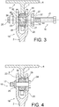
- the next assembly step consists of pushing the connector 7 carrying the seal 28 into the yoke 19 until the holes 21, 23 and 18 are aligned as well as the recess 36 in the center of the ring 29 of the seal 28 , giving the state represented in the figure 3 .
- the distance between the axial ends 32 and 33 in the axial direction XX of the seal 28 is a little greater than the distance between the internal faces of the cheeks 20 and 22, which has not prevented the introduction of the seal 28, thanks to the flexibility of the elastomer and to the rounded shape of the axial ends 32 and 33, by exerting a small force.
- the final stage of assembly is to install bolt 16 and tighten it.
- the rod 17 is threaded through the aligned bores 21, 23 and the recess 36, and also through a bore 37 in the center of the washer 27.
- the fit is tight with the second bore 23 and the bore 37, and with slightly greater play with the recess 36 in the loosened state of the bolt 16.
- the ring 29 of the seal 28 was then compressed in the axial direction XX between the washer 27 and the first cheek 20 by pushing back its axial ends 32 and 33, with the consequence that it expanded in the radial direction RR.
- the radial expansion is exerted inwards since it is prevented in the opposite direction by the support present from the initial state, on the radially outer side 31 on the outer sleeve 34.
- the ring 29 is therefore deformed to grip the ring. rod 17. It also provides a firm connection without play, but provided with flexibility, between the yoke 19 and the connector 7 by means of the conical washer 27 and the outer sleeve 34, which are respectively fixedly linked to them. .
- the stop of the conical faces limits the tightening of the ring 29.
- the figure 4 shows that the axial compression of the elastomer between the second cheek 19 and the washer 27, together with the compression of the elastomer enclosing the rod 17, with the absence of play between the seal 28 and the bore of the connector 7, and to the smallness of the clearances between the rod 17 and the bores 23 and 37, gives an assembly devoid of clearances and therefore particularly unlikely to see dynamic forces of vibrations and shocks appear between the support 6 and the spacer 2, of as much less as the elastomer has good damping properties, that it adapts to the shape or dimension tolerances of the constituents of the assembly and that it will also absorb small possible displacements of position or orientation between the two parts 2 and 5.
- the ring 29 is preferably incompressible (if for example it is made of an elastomer) or not very compressible, a moderate axial compression is sufficient to produce the radial expansion sufficient to grip the rod 17.
- the mechanical phenomenon exploited according to the invention of conversion of the axial compressive deformations of the ring 29 into radial expansion deformations, especially towards the interior, in order to grip the rod 17. This conversion largely depends on favorable form factors in the device and especially on the ring 29 to occur properly. It is recommended that the ring 29 have a regular shape overall, without discontinuity in direction or thickness.
- the edges of the axial ends 32 and 33 are connected to the intermediate part 44 by smooth junctions, without sharp angles, for example by gradually opening out towards it with a rounded shape.
- the intermediate part 44 extending between the axial ends 32 and 33 is cylindrical of constant thickness and of constant radius.
- the axial ends 32 and 33 have circular crown lines 45 and 46, the radius of which is closer to that of the radially inner side 30 than to the radially outer side 31, which promotes radial inward expansion of the ring 29 when it is compressed.
- Another favorable factor relates to the incompressibility of the material, that is to say to its ability to be compressed without reduction in volume: the rubber and in In general, elastomers, being absolutely or essentially incompressible, have the property of better converting axial compressive deformations into radial expansion deformations and are therefore preferred for constituting the ring 29.
- FIG 5 illustrates more fully another aspect of the invention: a spacer 39 composed, in addition to the first part 2, which is elongated and straight, of two opposite ends 40, 41, at least one of which is equipped with the device for connection already described, comprising in particular a yoke 19 equipped with a bolt 16.
- the parts connected by one or more spacers 39 and carrying male connectors 7 can be for example a stiffened structure 42 of an aircraft at the bottom, and a floor 43 up; many other applications are possible, the spacers 39 thus formed at their two ends can therefore be considered as connecting rods, capable of transmitting a possibly significant force in their direction of elongation.
- the flexibility of the ring 29 allows in particular a small misalignment between the recess 36 and the holes 21 and 23 of the cheeks 20 and 22 of the yoke 19, thus absorbing the position tolerances of the elements of the assembly and in particular of the length of the spacers 39.
- a mounting stress on the ring 29 is accepted, but which is in principle low compared to the stresses undergone in operation. It will be much less frequent than with the known designs to have to ensure the assembly by complicated measures such as the counter-drilling of the yoke 19, or the length adjustment of the spacer 39.
- the washer 27 could be integrated into the bolt 16 by being in one piece with the head 24.
- the ring 29 could be fixed to the connector 7 other than by the sleeve 34. It could have a section other than elliptical.
- the construction shown here is considered to be advantageous for the simplicity of manufacture of the elements and of assembly of the device. Many design or embodiment variants of the invention remain possible.
Landscapes
- Engineering & Computer Science (AREA)
- General Engineering & Computer Science (AREA)
- Mechanical Engineering (AREA)
- Aviation & Aerospace Engineering (AREA)
- Chemical & Material Sciences (AREA)
- Combustion & Propulsion (AREA)
- Physics & Mathematics (AREA)
- Acoustics & Sound (AREA)
- Bolts, Nuts, And Washers (AREA)
Abstract
Description
- Le sujet de l'invention est un dispositif de liaison comprenant une chape boulonnée et une bague déformable dans la chape.
- De tels dispositifs peuvent être utilisés dans l'aéronautique pour fixer notamment l'extrémité d'une entretoise d'étayage ou d'une autre pièce longiligne à une autre pièce telle qu'une structure de support, afin de transmettre un effort dans la direction d'extension de l'entretoise. Des applications non limitatives peuvent être l'attache ou le support de planchers, équipements, carénages ventraux, ou autres, à la structure d'un aéronef, et d'une façon générale tous les raccords où on souhaite éliminer les jeux.
- Un dispositif connu et illustré à la
figure 1 comprend une chape 1, formant un raccord femelle, à l'extrémité d'une première pièce 2 parmi les deux pièces à assembler, par exemple l'entretoise longiligne. La chape 1 est dotée de deux joues 3 planes et parallèles dont chacune est traversée par un perçage 4, les perçages 4 étant alignés et de même rayon. La première pièce 2 est assemblée à une seconde pièce 5 de l'assemblage, qui peut être une plaque 6 ou une autre structure de support, ici perpendiculaire à la première pièce 2 quand le montage est réalisé, et qui comprend un raccord 7 saillant comprenant un perçage 8 et formant un raccord mâle avec la chape 1. L'assemblage est accompli principalement par un boulon 9 dont une tête 10 et un écrou 11 de serrage s'appuient sur les faces externes des joues 3. Une tige 12 du boulon 9 traverse les perçages 4 et 8, qui sont alors alignés. L'assemblage est complété par deux douilles 13 et 14, toutes deux entourant la tige 12 et dont la première 13 est disposée dans le perçage 4 d'une des joues 3, et l'autre 14 est disposée dans le perçage 4 de l'autre des joues 3 ; cette dernière comprend à un bord une collerette 15 saillant autour de sa périphérie. - Un montage rigide est obtenu dans la direction axiale (X-X) de la tige 12 et de l'alignement des perçages du boulon 9, la première douille 13 étant comprimée entre le raccord 7 et la tête 10, et la seconde douille 14 étant comprimée entre le raccord 7 et l'écrou 9 ; de plus, la collerette 15 est comprimée entre le raccord 7 et la joue 3 adjacente, ce qui assure la position du raccord 7 dans cette direction. On notera encore qu'une rotule 38 est incorporée au raccord 7 pour permettre de petits ajustements d'orientation de la première pièce 2 par rapport à celui-ci.
- Les douilles 13 et 14 comprimées contribuent à absorber les jeux axiaux dans l'assemblage, mais des jeux radiaux (dans la direction radiale R-R perpendiculaire à la direction axiale X-X) subsistent entre la tige 12 du boulon 9 d'une part, et la rotule 38 du raccord 7 et éventuellement les douilles 13 et 14 d'autre part, même si ces dernières sont comprimées.
- Un objet de l'invention est de proposer un dispositif de liaison du genre mentionné, qui soit amélioré sous cet aspect : il est fondé principalement sur le remplacement des douilles du dispositif commenté ci-dessus par un joint apte à mieux combler les jeux pouvant apparaître entre les pièces principales de l'assemblage. Un meilleur amortissement contre les vibrations et le bruit pendant le service de l'aéronef peut être espéré. Ce joint est par ailleurs de constitution plus simple, et il autorise un montage simple et rapide de l'assemblage, ainsi que quelque souplesse d'ajustement de position ou d'orientation entre les deux pièces.
- Un aspect général de l'invention est ainsi un dispositif de liaison entre une première pièce, porteuse d'une chape à deux joues munies de perçages alignés, et une seconde pièce à extrémité munie d'un perçage, le dispositif comprenant, à un état de montage de la liaison, un boulon dont une tige traverse les perçages des joues et le perçage de l'extrémité aligné entre les perçages des joues dans une direction axiale, le boulon étant serré de part et d'autre des joues; et le dispositif étant caractérisé en ce que : une rondelle, en appui sur le boulon, pénètre dans le perçage de la première des joues; et le dispositif comprend encore un joint qui, à l'état de liaison, est fixé dans le perçage du raccord, ledit joint comprend une bague déformable munie d'un évidement traversé par la tige du boulon, la bague étant serrée radialement contre la tige du boulon et serrée axialement entre la rondelle et la seconde des joues autour du perçage de la seconde des joues à l'état de montage.
- Un effet important obtenu au montage du dispositif est une compression de la bague déformable dans sa direction axiale, qui produit alors une dilatation dans la direction radiale, apte à combler les jeux radiaux dans l'assemblage, surtout avec la surface de la tige du boulon. Le joint procure une liaison directe et ferme entre les deux pièces, en s'appuyant avec pression sur au moins une des joues et en étant étroitement ajusté dans le perçage du raccord mâle. Il enserre de plus la tige du boulon. Les douilles dans les perçages des joues deviennent inutiles et sont éliminées. Des petits mouvements relatifs entre les deux pièces restent possibles pour tolérer des ajustements de position ou d'orientation, grâce à la souplesse de l'élastomère. Les efforts dynamiques ne s'accompagnent pas de bruits ni de vibrations importantes grâce à l'amortissement procuré par l'élastomère. La rotule 38 devient inutile. Si le matériau de la bague est peu compressible ou incompressible (de l'élastomère par exemple, incompressible), une compression axiale modérée suffit à produire une dilatation radiale suffisante.
- Un autre aspect de l'invention est un ensemble de liaison, apte à donner le dispositif ci-dessus à l'état monté, et comprenant une entretoise à deux extrémités opposées, où l'entretoise comprend, à au moins une des extrémités, une chape à deux joues parallèles munies de perçages alignés dans une direction axiale ; caractérisé en ce que l'ensemble comprend encore : un joint annulaire qui comprend une bague déformable munie d'un évidement; un boulon dont une tige est apte à traverser l'évidement de la bague et les perçages des joues ; une rondelle apte à pénétrer dans le perçage de la première des joues et sur laquelle le boulon est apte à prendre appui ; la bague ayant une première extrémité axiale de rayon plus petit que le perçage de la première des joues, et une seconde extrémité axiale de rayon plus grand que le perçage de la seconde des joues.
- Selon divers aspects optionnels de l'invention :
- la bague possède des extrémités axiales alignées avec une partie intermédiaire de la bague dans la direction axiale, saillant du raccord de la seconde pièce dans la direction axiale et ayant des sections s'élargissant progressivement vers la partie intermédiaire de la bague ;
- les sections des extrémités axiales de la bague sont arrondies ;
- la bague a une section approximativement elliptique où la partie intermédiaire est délimitée par un côté cylindrique radialement intérieur rectiligne en direction axiale de la bague et un côté cylindrique radialement extérieur rectiligne en direction axiale de la bague, des bords des extrémités axiales se joignent auxdits côtés cylindriques, et les extrémités axiales de la bague ont des bords axiaux plus proches, dans une direction radiale, du côté cylindrique radialement intérieur que du côté cylindrique radialement extérieur ;
- la bague a, à un état libre, une longueur, dans la direction axiale, plus grande qu'une distance entre les joues de la chape ;
- la tige du boulon a un rayon plus petit qu'un rayon de l'évidement de la bague à un état de démontage de la liaison, où la bague n'est pas serrée contre la rondelle ;
- la bague est en matériau essentiellement incompressible, notamment en caoutchouc ou en élastomère ;
- le joint comprend une douille entourant la bague, à laquelle la bague est fixée, et qui est engagée sans jeu dans le perçage du raccord à l'état de montage du dispositif ;
- la douille est munie d'une collerette saillant extérieurement à un bord de la douille ;
- la rondelle a un bord extérieur conique, et le perçage de la première des joues a un bord conique de même angle de conicité ;
- le perçage d'une première des joues a un rayon plus grand que le perçage d'une seconde des joues ;
- la rondelle est séparée du boulon ;
- une tête du boulon est en appui/apte à venir en appui sur la rondelle.
- Un autre aspect de l'invention est une structure d'aéronef comprenant le dispositif ou l'ensemble de liaison, selon ce qui précède.
- L'invention sera maintenant décrite en détail au moyen d'une réalisation préférée de celle-ci, en liaison aux figures suivantes :
-
Fig. 1 déjà décrite représente un dispositif de liaison à chape connu, en coupe transversale à travers la chape ; -
Fig. 2 une réalisation de l'invention à l'état démonté, en coupe transversale à travers la chape ; -
Fig. 3 un état intermédiaire de montage de cette réalisation dans la même coupe ; -
Fig. 4 l'état monté de cette réalisation dans la même coupe ; -
Fig. 5 une entretoise conforme à l'invention, dans une coupe transversale partielle d'un aéronef ; -
Fig. 6 une vue semblable à celle de lafigure 2 , mais en perspective. - Le dispositif de l'invention est représenté (
figures 2 et6 ) pour la même application possible que celui de lafigure 1 , en reliant les pièces 2 et 5 ; celle-ci est de la même façon munie d'un raccord 7 saillant, mais dont le perçage 18 est ici droit et cylindrique et dépourvu de rotule ; et la chape 1 équipant la première pièce 2 est maintenant remplacée par une chape 19 un peu différente, dont une première joue 20 porte un premier perçage 21, et une seconde joue 22, parallèle à la précédente, porte un second perçage 23, de plus petit rayon que le précédent. De plus, le premier perçage 21 a un bord conique s'amenuisant vers l'intérieur de la chape 19. - L'assemblage est encore réalisé au moyen d'un boulon 16 comprenant une tige 17, une tête 24 à une extrémité de la tige 17, et, à l'autre extrémité de celle-ci, qui est filetée, un écrou 25. L'écrou 25 est destiné à s'appuyer sur la face extérieure de la seconde joue 22 par l'intermédiaire d'une rondelle 26 ; la tête 24 n'est toutefois pas destinée à s'appuyer sur la première joue 20, mais sur une rondelle 27 insérée dans le premier perçage 21, et dont le bord extérieur a une conicité identique à celui-ci.
- Et l'assemblage comprend encore un joint 28 comprenant une partie principale qui est une bague 29 déformable, ici en élastomère, la bague ayant une section ici approximativement elliptique et comprenant une partie intermédiaire 44, délimitée par un côté radialement intérieur 30 cylindrique et un côté radialement extérieur 31 cylindrique et plus court que le précédent, et deux extrémités axiales 32 et 33 aux extrémités de la partie intermédiaire 44 en faisant saillie dans la direction axiale du joint 28, qui coïncide avec la direction axiale X-X déjà introduite et qui est celle de la tige (ici 17) et de l'alignement des perçages (ici 21 et 23). Les extrémités axiales 32 et 33 ont une section arrondie, à peu près semi-circulaire, et leur contour se raccorde aux extrémités des côtés radialement intérieur 30 et radialement extérieur 31. D'autres formes de la bague déformable seraient possibles, des sections arrondies aux extrémités longitudinales pouvant cependant être préférées pour faciliter un serrage progressif et une insertion plus facile dans la chape 19. L'élastomère est un matériau apprécié ici puisqu'il est non seulement déformable mais incompressible, bien élastique et de bonne résistance mécanique à l'écrasement, mais d'autres matériaux déformables, comme des polymères et en particulier des thermoplastiques, pourraient convenir, d'après les sollicitations mécaniques ou thermiques auxquelles la bague devrait résister. Le joint 28 comprend encore une douille extérieure 34 à laquelle la bague 29 est fixée par le côté radialement extérieur 31, et qui est munie d'une collerette 35 à une extrémité. Le côté radialement intérieur 30 reste dégagé pour venir directement au contact de la tige 17. Un évidement central de la bague 29, qu'entoure le côté radialement intérieur 30, porte la référence 36 et sa longueur s'étend aussi dans la direction axiale X-X.
- A un état complètement démonté du dispositif, qui n'est pas représenté ici, le joint 28 est libre. Une première étape du montage consiste à l'insérer dans le perçage 18 du raccord 7. Comme la douille 34 n'a pas de jeu, ou a un léger jeu négatif, avec le perçage 18, l'ajustement se fait à la presse ou par un moyen analogue. Le joint 28 est alors fixé au raccord 7, à une position axiale déterminée par la butée de la collerette 35 contre une face latérale plane du raccord 7, et cette position reste invariable.
- L'étape suivante du montage consiste à pousser le raccord 7 porteur du joint 28 dans la chape 19 jusqu'à réaliser l'alignement des perçages 21, 23 et 18 ainsi que de l'évidement 36 au centre de la bague 29 du joint 28, en donnant l'état représenté à la
figure 3 . La distance entre les extrémités axiales 32 et 33 dans la direction axiale X-X du joint 28 est un peu plus grande que l'écart entre les faces internes des joues 20 et 22, ce qui n'a pas empêché l'introduction du joint 28, grâce à la souplesse de l'élastomère et à la forme arrondie des extrémités axiales 32 et 33, en exerçant un petit effort. - L'étape finale du montage, donnant l'état de la
figure 4 , consiste à installer le boulon 16 et à le serrer. La tige 17 est enfilée dans les perçages 21, 23 et l'évidement 36 alignés, et aussi à travers un perçage 37 au centre de la rondelle 27. L'ajustement est à petit jeu avec le second perçage 23 et le perçage 37, et à jeu légèrement plus important avec l'évidement 36 à l'état desserré du boulon 16. Quand l'écrou 25 est vissé, il s'appuie par l'intermédiaire de la rondelle 27 sur la face externe de la seconde joue 20 tandis que la tête 24 s'appuie sur la face extérieure de la rondelle 27 et l'enfonce dans le premier perçage 21 jusqu'à la butée des faces coniques. La bague 29 du joint 28 a alors été comprimée dans la direction axiale X-X entre la rondelle 27 et la première joue 20 en repoussant ses extrémités axiales 32 et 33, avec la conséquence qu'elle s'est dilatée dans la direction radiale R-R. La dilatation radiale s'exerce vers l'intérieur puisqu'elle est empêchée dans le sens opposé par l'appui présent dès l'état initial, du côté radialement extérieur 31 sur la douille extérieure 34. La bague 29 est donc déformée pour enserrer la tige 17. Elle réalise aussi une liaison ferme et sans jeu, mais pourvue de souplesse, entre la chape 19 et le raccord 7 par l'intermédiaire de la rondelle 27 conique et de la douille extérieure 34, qui leur sont respectivement liées de façon fixe. La butée des faces coniques limite le serrage de la bague 29. - La
figure 4 montre que la compression axiale de l'élastomère entre la seconde joue 19 et la rondelle 27, jointe à la compression de l'élastomère enserrant la tige 17, à l'absence de jeu entre le joint 28 et le perçage du raccord 7, et à la modicité des jeux entre la tige 17 et les perçages 23 et 37, donne un montage dépourvu de jeux et donc particulièrement peu apte à voir apparaître des efforts dynamiques de vibrations et de chocs entre le support 6 et l'entretoise 2, d'autant moins que l'élastomère a de bonnes facultés d'amortissement, qu'il s'adapte aux tolérances de forme ou de dimension des constituants de l'assemblage et qu'il absorbera aussi de petits déplacements éventuels de position ou d'orientation entre les deux pièces 2 et 5. Comme la bague 29 est de préférence incompressible (si par exemple elle est en élastomère) ou peu compressible, une compression axiale modérée suffit à produire la dilatation radiale suffisant à enserrer la tige 17. - Il convient ici de décrire plus longuement le phénomène mécanique exploité d'après l'invention, de conversion des déformations axiales de compression de la bague 29 en déformations radiales d'expansion, surtout vers l'intérieur, afin d'enserrer la tige 17. Cette conversion dépend en grande partie de facteurs de forme favorables dans le dispositif et surtout de la bague 29 pour se produire convenablement. On préconise que la bague 29 ait une forme régulière dans l'ensemble, sans discontinuité de direction ou d'épaisseur. Les bords des extrémités axiales 32 et 33 se raccordent à la partie intermédiaire 44 par des jonctions lisses, sans angle vif, par exemple en s'épanouissant progressivement vers elle avec une forme arrondie. La partie intermédiaire 44 s'étendant entre les extrémités axiales 32 et 33 est cylindrique d'épaisseur constante et de rayon constant. Cela permet aux extrémités axiales 32 et 33 et à la partie intermédiaire 44 de se trouver en alignement axial, dans la direction de serrage, et permet aussi une transmission d'efforts uniformes de compression axiale dans la partie intermédiaire 44, dont l'épaisseur est uniforme. Les extrémités axiales 32 et 33 diffusent les déformations de compression dans toute l'épaisseur de la partie intermédiaire 44, grâce au contour régulier, presque semi-circulaire, de leur section, et à l'absence d'appui ou de contact quelconque sur les pièces voisines, en particulier sur la douille extérieure 34 et le raccord 7, parce que la partie intermédiaire 44 est plus longue que la douille extérieure 34 et que le perçage 18 du raccord 7. Il faut encore remarquer que les extrémités axiales 32 et 33 ont des lignes de sommet 45 et 46 circulaires dont le rayon est plus proche de celui du côté radialement intérieur 30 que du côté radialement extérieur 31, ce qui favorise l'expansion radiale vers l'intérieur de la bague 29 quand elle est comprimée.
- Toutes ces caractéristiques contribuent à l'obtention d'une déformation radiale suffisante de la bague 29 vers l'intérieur quand elle est comprimée, garantissant un serrage ferme de la tige 17 pour des assemblages de formes et dimensions ordinaires. Ce résultat ne serait pas assuré avec des bagues élastiques quelconques, surtout les bagues courantes dans l'industrie, dont les extrémités s'élargissent radialement en collerettes plates reposant sur les pièces de l'assemblage.
- Un autre facteur favorable est relatif à l'incompressibilité du matériau, c'est-à-dire à sa faculté d'être comprimé sans diminution de volume : le caoutchouc et en général les élastomères, étant absolument ou essentiellement incompressibles, ont la propriété de mieux convertir les déformations axiales de compression en déformations radiales d'expansion et sont donc préférés pour constituer la bague 29.
- La
figure 5 illustre plus complètement un autre aspect de l'invention : une entretoise 39 composée, outre de la première pièce 2, qui est longiligne et droite, de deux extrémités 40, 41 opposées dont au moins l'une d'elles est équipée du dispositif de liaison déjà décrit, comprenant notamment une chape 19 équipée d'un boulon 16. Les pièces reliées par une ou plusieurs entretoises 39 et porteuses des raccords 7 mâles peuvent être par exemple une structure raidie 42 d'un aéronef en bas, et un plancher 43 en haut; bien d'autres applications sont possibles, les entretoises 39 ainsi constituées à leur deux extrémités pouvant donc être considérées comme des bielles de liaison, aptes à transmettre un effort éventuellement important dans leur direction d'allongement. La souplesse de la bague 29 permet notamment un petit désalignement entre l'évidement 36 et les perçages 21 et 23 des joues 20 et 22 de la chape 19, en absorbant donc des tolérances de position des éléments de l'assemblage et notamment de longueur des entretoises 39. Une contrainte de montage sur la bague 29 est acceptée, mais qui est en principe faible par rapport aux contraintes subies en fonctionnement. Il sera beaucoup moins fréquent qu'avec les conceptions connues de devoir assurer l'assemblage par des mesures compliquées telles que le contre-perçage de la chape 19, ou l'ajustement de longueur de l'entretoise 39. - La rondelle 27 pourrait être intégrée au boulon 16 en étant d'une pièce avec la tête 24. La bague 29 pourrait être fixée au raccord 7 autrement que par la douille 34. Elle pourrait avoir une autre section qu'elliptique. La construction représentée ici est considérée comme avantageuse pour la simplicité de fabrication des éléments et de montage du dispositif. Bien des variantes de conception ou de réalisation de l'invention restent possibles.
Claims (15)
- Dispositif de liaison entre une première pièce (2), porteuse d'une chape (19) à deux joues (20, 22) munies de perçages (21, 23) alignés, et une seconde pièce (5) à raccord (7) muni d'un perçage (18), le dispositif comprenant, à un état de montage de la liaison, un boulon (16) dont une tige (17) traverse les perçages (21, 23) des joues (20, 22) et le perçage (18) de l'extrémité (7) aligné entre les perçages des joues dans une direction axiale, le boulon (16) étant serré de part et d'autre des joues ; et le dispositif étant caractérisé en ce que : une rondelle (27), sur laquelle le boulon (16) s'appuie, pénètre dans le perçage de la première des joues (20) ; et le dispositif comprend encore un joint (28) annulaire qui, à l'état de liaison, est fixé dans le perçage (18) du raccord (7), ledit joint (17) comprend une bague (29) déformable munie d'un évidement (36) traversé par la tige du boulon, ladite portion principale étant serrée radialement contre la tige (17) du boulon et serrée axialement entre la rondelle (27) et la seconde des joues (22) à l'état de montage.
- Ensemble de liaison comprenant une entretoise (39) à deux extrémités opposées, où l'entretoise comprend, à au moins une des extrémités, une chape (19) à deux joues (20, 22) parallèles munies de perçages (21, 23) alignés dans une direction axiale ; caractérisé en ce que l'ensemble comprend encore : un joint (28) annulaire qui comprend une bague (29) déformable munie d'un évidement (36) ; un boulon (16) dont une tige (17) est apte à traverser l'évidement (36) de la bague (29) et les perçages des joues ; une rondelle (27) apte à pénétrer dans le perçage de la première des joues et sur laquelle le boulon est apte à prendre appui ; la bague ayant une première extrémité axiale de rayon plus petit que le perçage de la première des joues, et une seconde extrémité axiale de rayon plus grand que le perçage de la seconde des joues.
- Dispositif ou ensemble de liaison selon la revendication 1 ou 2, caractérisé en ce que la bague (29) possède des extrémités axiales (32, 33) alignées avec une partie intermédiaire de la bague dans la direction axiale, saillant du raccord (7) de la seconde pièce (5) dans la direction axiale et ayant des sections s'élargissant progressivement vers la partie intermédiaire de la bague.
- Dispositif ou ensemble de liaison selon la revendication 3, caractérisé en ce que les sections des extrémités axiales (32, 33) de la bague sont arrondies.
- Dispositif ou ensemble de liaison selon la revendication 3 ou 4, caractérisé en ce que la bague (29) a une section approximativement elliptique où la partie intermédiaire (44) est délimitée par un côté cylindrique radialement intérieur (30) rectiligne en direction axiale (X-X) de la bague et un côté cylindrique radialement extérieur (31) rectiligne en direction axiale de la bague, et les extrémités axiales de la bague ont des lignes circulaires de sommet (45, 46) plus proches, dans une direction radiale, du côté cylindrique radialement intérieur (30) que du côté cylindrique radialement extérieur (31).
- Dispositif ou ensemble de liaison selon l'une quelconque des revendications 1 à 5, caractérisé en ce que la bague (29) a, à un état libre, une longueur, dans la direction axiale, plus grande qu'une distance entre les joues (20, 22) de la chape.
- Dispositif ou ensemble de liaison selon l'une quelconque des revendications 1 à 6, caractérisé en ce que la tige (17) du boulon a un rayon plus petit qu'un rayon de l'évidement (36) de la bague (29) à un état de démontage de la liaison, où la bague (29) n'est pas serrée contre la rondelle (27).
- Dispositif ou ensemble de liaison selon l'une quelconque des revendications 1 à 7, caractérisé en ce que la bague est en matériau essentiellement incompressible, notamment en caoutchouc ou en élastomère.
- Dispositif ou ensemble de liaison selon l'une quelconque des revendications 1 à 8, caractérisé en ce que le joint comprend une douille (34) entourant la bague (29), à laquelle la bague est fixée, et qui est engagée sans jeu dans le perçage (18) du raccord (7) à l'état de montage du dispositif.
- Dispositif ou ensemble de liaison selon la revendication 9, caractérisé en ce que la douille (34) est munie d'une collerette (35) saillant extérieurement à un bord de la douille.
- Dispositif ou ensemble de liaison selon l'une quelconque des revendications 1 à 10, caractérisé en ce que la rondelle (27) est conique, et le perçage (21) de la première des joues (20) est conique avec un même angle de conicité.
- Dispositif ou ensemble de liaison selon l'une quelconque des revendications 1 à 11, caractérisé en ce que le perçage (21) d'une première des joues (20) a un rayon plus grand que le perçage (23) d'une seconde des joues (22).
- Dispositif ou ensemble de liaison selon l'une quelconque des revendications 1 à 12, caractérisé en ce que la rondelle (27) est séparée du boulon (16).
- Dispositif ou ensemble de serrage selon la revendication 13, caractérisé en ce qu'une tête (24) du boulon est en appui/apte à venir en appui sur la rondelle.
- Structure d'aéronef, caractérisée en ce qu'elle comporte un dispositif de liaison et/ou un ensemble de liaison selon l'une quelconque des revendications précédentes.
Applications Claiming Priority (1)
| Application Number | Priority Date | Filing Date | Title |
|---|---|---|---|
| FR1913410A FR3103864A1 (fr) | 2019-11-28 | 2019-11-28 | Dispositif de liaison comprenant une chape boulonnée et une bague déformable dans la chape |
Publications (2)
| Publication Number | Publication Date |
|---|---|
| EP3828428A1 true EP3828428A1 (fr) | 2021-06-02 |
| EP3828428B1 EP3828428B1 (fr) | 2023-10-25 |
Family
ID=69468907
Family Applications (1)
| Application Number | Title | Priority Date | Filing Date |
|---|---|---|---|
| EP20209194.8A Active EP3828428B1 (fr) | 2019-11-28 | 2020-11-23 | Dispositif de liaison comprenant une chape boulonnée et une bague déformable dans la chape |
Country Status (4)
| Country | Link |
|---|---|
| US (1) | US11686340B2 (fr) |
| EP (1) | EP3828428B1 (fr) |
| CN (1) | CN112855740A (fr) |
| FR (1) | FR3103864A1 (fr) |
Families Citing this family (5)
| Publication number | Priority date | Publication date | Assignee | Title |
|---|---|---|---|---|
| US11820510B2 (en) * | 2019-03-26 | 2023-11-21 | Yaborã Industria Aeronautica S.A. | Quickly adjustable fail-safe link bar assemblies especially useful for connecting structural components of an aircraft |
| FR3118755B1 (fr) * | 2021-01-13 | 2023-03-24 | Safran Landing Systems | Dispositif de liaison de pièces mécaniques avec jeu axial |
| CN114408209B (zh) * | 2021-12-28 | 2024-01-12 | 中国飞机强度研究所 | 一种合力点双耳与杠杆传载系统的连接方法和连接结构 |
| CN117028389B (zh) * | 2023-10-10 | 2024-01-26 | 太原理工大学 | 充盈式螺纹铆接的抗剪紧固件及其使用方法 |
| FR3167920A1 (fr) * | 2024-10-25 | 2026-05-01 | Airbus Operations (S.A.S) | Dispositif de jonction pour aéronef permettant un degré de liberté dans une direction |
Citations (3)
| Publication number | Priority date | Publication date | Assignee | Title |
|---|---|---|---|---|
| US1954277A (en) * | 1930-10-24 | 1934-04-10 | Oscar U Zerk | Cushioning means and method for mechanical joints |
| US2659619A (en) * | 1947-01-24 | 1953-11-17 | Nash Kelvinator Corp | Resilient connection |
| US2824464A (en) * | 1954-01-13 | 1958-02-25 | Studebaker Packard Corp | Hinged pedal structure |
Family Cites Families (11)
| Publication number | Priority date | Publication date | Assignee | Title |
|---|---|---|---|---|
| US2346574A (en) * | 1942-09-17 | 1944-04-11 | Guy & Murton Inc | Resilient bushing |
| US2819105A (en) * | 1955-08-17 | 1958-01-07 | Kay Brunner Steel Products Inc | Bushings for oscillating joints |
| US3085773A (en) * | 1960-02-01 | 1963-04-16 | North American Aviation Inc | Adjustable engine mount |
| FR1220845A (fr) * | 1960-09-26 | 1960-05-27 | Eaton Axles Ltd | Perfectionnements aux ensembles de suspension d'essieux en tandem |
| US4062637A (en) * | 1975-07-07 | 1977-12-13 | Ford Motor Company | Steering linkage and tie rod assembly |
| US4077655A (en) * | 1977-04-27 | 1978-03-07 | J. I. Case Company | Shock mount for protective structure for tractors |
| US4139245A (en) * | 1977-06-03 | 1979-02-13 | The Heim Universal Corp. | Vibration damping in machine element bearings |
| DE3141869C2 (de) * | 1981-10-22 | 1984-02-02 | Messerschmitt-Bölkow-Blohm GmbH, 8000 München | Fußbodenkonstruktion für den oberen Laderaum eines Luftfahrzeuges |
| US4684280A (en) * | 1986-04-14 | 1987-08-04 | Pneumo Abex Corporation | Clevis connection |
| US5058829A (en) * | 1990-01-12 | 1991-10-22 | Weber Aircraft | Seat track fitting |
| US7954793B2 (en) * | 2006-12-08 | 2011-06-07 | Enidine, Inc. | Elastomeric isolator |
-
2019
- 2019-11-28 FR FR1913410A patent/FR3103864A1/fr not_active Ceased
-
2020
- 2020-11-23 EP EP20209194.8A patent/EP3828428B1/fr active Active
- 2020-11-25 US US17/104,225 patent/US11686340B2/en active Active
- 2020-11-27 CN CN202011357070.4A patent/CN112855740A/zh active Pending
Patent Citations (3)
| Publication number | Priority date | Publication date | Assignee | Title |
|---|---|---|---|---|
| US1954277A (en) * | 1930-10-24 | 1934-04-10 | Oscar U Zerk | Cushioning means and method for mechanical joints |
| US2659619A (en) * | 1947-01-24 | 1953-11-17 | Nash Kelvinator Corp | Resilient connection |
| US2824464A (en) * | 1954-01-13 | 1958-02-25 | Studebaker Packard Corp | Hinged pedal structure |
Also Published As
| Publication number | Publication date |
|---|---|
| CN112855740A (zh) | 2021-05-28 |
| FR3103864A1 (fr) | 2021-06-04 |
| EP3828428B1 (fr) | 2023-10-25 |
| US20210163115A1 (en) | 2021-06-03 |
| US11686340B2 (en) | 2023-06-27 |
Similar Documents
| Publication | Publication Date | Title |
|---|---|---|
| EP3828428B1 (fr) | Dispositif de liaison comprenant une chape boulonnée et une bague déformable dans la chape | |
| EP1950392B1 (fr) | Dispositif d'assemblage de deux ensembles, par exemple pour stator de turbomachine | |
| EP0857274B1 (fr) | Dispositif de liaison d'un tube a un embout | |
| FR2947523A1 (fr) | Element de fuselage comportant un troncon de fuselage et des moyens de jonction | |
| FR2960039A1 (fr) | Dispositif de raccordement de tubes de protection d'un cable a fibres optiques, troncon d'un circuit de transmission optique comportant un tel dispositif et element d'etancheite pour un tel dispositif | |
| FR2490752A1 (fr) | Accouplement de serrage | |
| FR2865319A1 (fr) | Dispositif de connexion et manchon de contact | |
| EP4571164A1 (fr) | Dispositif de raccordement fluidique et ensemble de raccordement fluidique comprenant un tel dispositif de raccordement fluidique | |
| EP0375515B1 (fr) | Dispositif de liaison démontable entre deux pièces soumises à de fortes sollicitations | |
| FR2914789A1 (fr) | Accessoire du type a capot de blindage pour connecteur | |
| FR2691767A1 (fr) | Dispositif de liaison élastique à rotule. | |
| FR3123395A1 (fr) | Ensemble de liaison de type double excentrique comprenant une bague en materiau deformable, pour une liaison entre deux structures d’un aeronef, et aeronef comprenant un tel ensemble | |
| EP0124430B1 (fr) | Dispositif de raccordement télédémontable | |
| FR2488954A1 (fr) | Dispositif de fixation de rotules de bielles, et procede pour la mise en place de rotules dans un tel dispositif | |
| EP4259943B1 (fr) | Dispositif de fixation mecanique a l'extremite d'un tube | |
| FR2529272A1 (fr) | Element d'arret axial | |
| FR3029260A1 (fr) | Garniture de joint a verrouillage mecanique comportant deux zones d'etancheite et sa mise en oeuvre pour realiser une jonction tubulaire flexible verrouillee | |
| FR2902240A1 (fr) | Contact de type douille elastique monobloc a insertion de force controlee | |
| FR2787765A1 (fr) | Dispositif de support d'une charge utile dans un lanceur de ladite charge utile | |
| BE527928A (fr) | ||
| EP3862595B1 (fr) | Dispositif de liaison élastique entre deux pièces concentriques et assemblage comportant un tel dispositif de liaison élastique | |
| FR2652623A1 (fr) | Dispositif de butee d'embrayage a autocentrage du type tiree. | |
| FR3026151A1 (fr) | Dispositif d'assemblage a ecrou-barillet, ensemble structurel d'aeronef comprenant un tel dispositif, et procede d'assemblage correspondant | |
| FR2809651A1 (fr) | Pince a emboiture | |
| EP2470819A1 (fr) | Pont amortissant |
Legal Events
| Date | Code | Title | Description |
|---|---|---|---|
| PUAI | Public reference made under article 153(3) epc to a published international application that has entered the european phase |
Free format text: ORIGINAL CODE: 0009012 |
|
| STAA | Information on the status of an ep patent application or granted ep patent |
Free format text: STATUS: THE APPLICATION HAS BEEN PUBLISHED |
|
| AK | Designated contracting states |
Kind code of ref document: A1 Designated state(s): AL AT BE BG CH CY CZ DE DK EE ES FI FR GB GR HR HU IE IS IT LI LT LU LV MC MK MT NL NO PL PT RO RS SE SI SK SM TR |
|
| STAA | Information on the status of an ep patent application or granted ep patent |
Free format text: STATUS: REQUEST FOR EXAMINATION WAS MADE |
|
| 17P | Request for examination filed |
Effective date: 20211129 |
|
| RBV | Designated contracting states (corrected) |
Designated state(s): AL AT BE BG CH CY CZ DE DK EE ES FI FR GB GR HR HU IE IS IT LI LT LU LV MC MK MT NL NO PL PT RO RS SE SI SK SM TR |
|
| GRAP | Despatch of communication of intention to grant a patent |
Free format text: ORIGINAL CODE: EPIDOSNIGR1 |
|
| STAA | Information on the status of an ep patent application or granted ep patent |
Free format text: STATUS: GRANT OF PATENT IS INTENDED |
|
| RIC1 | Information provided on ipc code assigned before grant |
Ipc: F16C 11/08 20060101ALN20230214BHEP Ipc: F16C 11/06 20060101ALN20230214BHEP Ipc: F16C 9/06 20060101ALI20230214BHEP Ipc: F16C 9/03 20060101ALI20230214BHEP Ipc: F16C 7/02 20060101ALI20230214BHEP Ipc: F16C 11/04 20060101AFI20230214BHEP |
|
| INTG | Intention to grant announced |
Effective date: 20230315 |
|
| GRAJ | Information related to disapproval of communication of intention to grant by the applicant or resumption of examination proceedings by the epo deleted |
Free format text: ORIGINAL CODE: EPIDOSDIGR1 |
|
| STAA | Information on the status of an ep patent application or granted ep patent |
Free format text: STATUS: REQUEST FOR EXAMINATION WAS MADE |
|
| GRAP | Despatch of communication of intention to grant a patent |
Free format text: ORIGINAL CODE: EPIDOSNIGR1 |
|
| STAA | Information on the status of an ep patent application or granted ep patent |
Free format text: STATUS: GRANT OF PATENT IS INTENDED |
|
| INTC | Intention to grant announced (deleted) | ||
| RIC1 | Information provided on ipc code assigned before grant |
Ipc: F16C 11/08 20060101ALN20230516BHEP Ipc: F16C 11/06 20060101ALN20230516BHEP Ipc: F16C 9/06 20060101ALI20230516BHEP Ipc: F16C 9/03 20060101ALI20230516BHEP Ipc: F16C 7/02 20060101ALI20230516BHEP Ipc: F16C 11/04 20060101AFI20230516BHEP |
|
| INTG | Intention to grant announced |
Effective date: 20230531 |
|
| GRAS | Grant fee paid |
Free format text: ORIGINAL CODE: EPIDOSNIGR3 |
|
| GRAA | (expected) grant |
Free format text: ORIGINAL CODE: 0009210 |
|
| STAA | Information on the status of an ep patent application or granted ep patent |
Free format text: STATUS: THE PATENT HAS BEEN GRANTED |
|
| AK | Designated contracting states |
Kind code of ref document: B1 Designated state(s): AL AT BE BG CH CY CZ DE DK EE ES FI FR GB GR HR HU IE IS IT LI LT LU LV MC MK MT NL NO PL PT RO RS SE SI SK SM TR |
|
| REG | Reference to a national code |
Ref country code: GB Ref legal event code: FG4D Free format text: NOT ENGLISH |
|
| REG | Reference to a national code |
Ref country code: CH Ref legal event code: EP |
|
| REG | Reference to a national code |
Ref country code: DE Ref legal event code: R096 Ref document number: 602020019754 Country of ref document: DE |
|
| REG | Reference to a national code |
Ref country code: IE Ref legal event code: FG4D Free format text: LANGUAGE OF EP DOCUMENT: FRENCH |
|
| REG | Reference to a national code |
Ref country code: LT Ref legal event code: MG9D |
|
| REG | Reference to a national code |
Ref country code: NL Ref legal event code: MP Effective date: 20231025 |
|
| REG | Reference to a national code |
Ref country code: AT Ref legal event code: MK05 Ref document number: 1624930 Country of ref document: AT Kind code of ref document: T Effective date: 20231025 |
|
| PG25 | Lapsed in a contracting state [announced via postgrant information from national office to epo] |
Ref country code: NL Free format text: LAPSE BECAUSE OF FAILURE TO SUBMIT A TRANSLATION OF THE DESCRIPTION OR TO PAY THE FEE WITHIN THE PRESCRIBED TIME-LIMIT Effective date: 20231025 |
|
| PG25 | Lapsed in a contracting state [announced via postgrant information from national office to epo] |
Ref country code: GR Free format text: LAPSE BECAUSE OF FAILURE TO SUBMIT A TRANSLATION OF THE DESCRIPTION OR TO PAY THE FEE WITHIN THE PRESCRIBED TIME-LIMIT Effective date: 20240126 |
|
| PG25 | Lapsed in a contracting state [announced via postgrant information from national office to epo] |
Ref country code: IS Free format text: LAPSE BECAUSE OF FAILURE TO SUBMIT A TRANSLATION OF THE DESCRIPTION OR TO PAY THE FEE WITHIN THE PRESCRIBED TIME-LIMIT Effective date: 20240225 |
|
| PG25 | Lapsed in a contracting state [announced via postgrant information from national office to epo] |
Ref country code: LT Free format text: LAPSE BECAUSE OF FAILURE TO SUBMIT A TRANSLATION OF THE DESCRIPTION OR TO PAY THE FEE WITHIN THE PRESCRIBED TIME-LIMIT Effective date: 20231025 |
|
| PG25 | Lapsed in a contracting state [announced via postgrant information from national office to epo] |
Ref country code: AT Free format text: LAPSE BECAUSE OF FAILURE TO SUBMIT A TRANSLATION OF THE DESCRIPTION OR TO PAY THE FEE WITHIN THE PRESCRIBED TIME-LIMIT Effective date: 20231025 |
|
| PG25 | Lapsed in a contracting state [announced via postgrant information from national office to epo] |
Ref country code: ES Free format text: LAPSE BECAUSE OF FAILURE TO SUBMIT A TRANSLATION OF THE DESCRIPTION OR TO PAY THE FEE WITHIN THE PRESCRIBED TIME-LIMIT Effective date: 20231025 |
|
| PG25 | Lapsed in a contracting state [announced via postgrant information from national office to epo] |
Ref country code: LT Free format text: LAPSE BECAUSE OF FAILURE TO SUBMIT A TRANSLATION OF THE DESCRIPTION OR TO PAY THE FEE WITHIN THE PRESCRIBED TIME-LIMIT Effective date: 20231025 Ref country code: IS Free format text: LAPSE BECAUSE OF FAILURE TO SUBMIT A TRANSLATION OF THE DESCRIPTION OR TO PAY THE FEE WITHIN THE PRESCRIBED TIME-LIMIT Effective date: 20240225 Ref country code: GR Free format text: LAPSE BECAUSE OF FAILURE TO SUBMIT A TRANSLATION OF THE DESCRIPTION OR TO PAY THE FEE WITHIN THE PRESCRIBED TIME-LIMIT Effective date: 20240126 Ref country code: ES Free format text: LAPSE BECAUSE OF FAILURE TO SUBMIT A TRANSLATION OF THE DESCRIPTION OR TO PAY THE FEE WITHIN THE PRESCRIBED TIME-LIMIT Effective date: 20231025 Ref country code: BG Free format text: LAPSE BECAUSE OF FAILURE TO SUBMIT A TRANSLATION OF THE DESCRIPTION OR TO PAY THE FEE WITHIN THE PRESCRIBED TIME-LIMIT Effective date: 20240125 Ref country code: AT Free format text: LAPSE BECAUSE OF FAILURE TO SUBMIT A TRANSLATION OF THE DESCRIPTION OR TO PAY THE FEE WITHIN THE PRESCRIBED TIME-LIMIT Effective date: 20231025 Ref country code: PT Free format text: LAPSE BECAUSE OF FAILURE TO SUBMIT A TRANSLATION OF THE DESCRIPTION OR TO PAY THE FEE WITHIN THE PRESCRIBED TIME-LIMIT Effective date: 20240226 |
|
| PG25 | Lapsed in a contracting state [announced via postgrant information from national office to epo] |
Ref country code: SE Free format text: LAPSE BECAUSE OF FAILURE TO SUBMIT A TRANSLATION OF THE DESCRIPTION OR TO PAY THE FEE WITHIN THE PRESCRIBED TIME-LIMIT Effective date: 20231025 Ref country code: RS Free format text: LAPSE BECAUSE OF FAILURE TO SUBMIT A TRANSLATION OF THE DESCRIPTION OR TO PAY THE FEE WITHIN THE PRESCRIBED TIME-LIMIT Effective date: 20231025 Ref country code: PL Free format text: LAPSE BECAUSE OF FAILURE TO SUBMIT A TRANSLATION OF THE DESCRIPTION OR TO PAY THE FEE WITHIN THE PRESCRIBED TIME-LIMIT Effective date: 20231025 Ref country code: NO Free format text: LAPSE BECAUSE OF FAILURE TO SUBMIT A TRANSLATION OF THE DESCRIPTION OR TO PAY THE FEE WITHIN THE PRESCRIBED TIME-LIMIT Effective date: 20240125 Ref country code: LV Free format text: LAPSE BECAUSE OF FAILURE TO SUBMIT A TRANSLATION OF THE DESCRIPTION OR TO PAY THE FEE WITHIN THE PRESCRIBED TIME-LIMIT Effective date: 20231025 Ref country code: HR Free format text: LAPSE BECAUSE OF FAILURE TO SUBMIT A TRANSLATION OF THE DESCRIPTION OR TO PAY THE FEE WITHIN THE PRESCRIBED TIME-LIMIT Effective date: 20231025 |
|
| REG | Reference to a national code |
Ref country code: CH Ref legal event code: PL |
|
| PG25 | Lapsed in a contracting state [announced via postgrant information from national office to epo] |
Ref country code: DK Free format text: LAPSE BECAUSE OF FAILURE TO SUBMIT A TRANSLATION OF THE DESCRIPTION OR TO PAY THE FEE WITHIN THE PRESCRIBED TIME-LIMIT Effective date: 20231025 |
|
| PG25 | Lapsed in a contracting state [announced via postgrant information from national office to epo] |
Ref country code: LU Free format text: LAPSE BECAUSE OF NON-PAYMENT OF DUE FEES Effective date: 20231123 |
|
| PG25 | Lapsed in a contracting state [announced via postgrant information from national office to epo] |
Ref country code: CH Free format text: LAPSE BECAUSE OF NON-PAYMENT OF DUE FEES Effective date: 20231130 |
|
| PG25 | Lapsed in a contracting state [announced via postgrant information from national office to epo] |
Ref country code: CZ Free format text: LAPSE BECAUSE OF FAILURE TO SUBMIT A TRANSLATION OF THE DESCRIPTION OR TO PAY THE FEE WITHIN THE PRESCRIBED TIME-LIMIT Effective date: 20231025 |
|
| REG | Reference to a national code |
Ref country code: DE Ref legal event code: R097 Ref document number: 602020019754 Country of ref document: DE |
|
| PG25 | Lapsed in a contracting state [announced via postgrant information from national office to epo] |
Ref country code: SK Free format text: LAPSE BECAUSE OF FAILURE TO SUBMIT A TRANSLATION OF THE DESCRIPTION OR TO PAY THE FEE WITHIN THE PRESCRIBED TIME-LIMIT Effective date: 20231025 |
|
| PG25 | Lapsed in a contracting state [announced via postgrant information from national office to epo] |
Ref country code: SM Free format text: LAPSE BECAUSE OF FAILURE TO SUBMIT A TRANSLATION OF THE DESCRIPTION OR TO PAY THE FEE WITHIN THE PRESCRIBED TIME-LIMIT Effective date: 20231025 Ref country code: SK Free format text: LAPSE BECAUSE OF FAILURE TO SUBMIT A TRANSLATION OF THE DESCRIPTION OR TO PAY THE FEE WITHIN THE PRESCRIBED TIME-LIMIT Effective date: 20231025 Ref country code: RO Free format text: LAPSE BECAUSE OF FAILURE TO SUBMIT A TRANSLATION OF THE DESCRIPTION OR TO PAY THE FEE WITHIN THE PRESCRIBED TIME-LIMIT Effective date: 20231025 Ref country code: LU Free format text: LAPSE BECAUSE OF NON-PAYMENT OF DUE FEES Effective date: 20231123 Ref country code: IT Free format text: LAPSE BECAUSE OF FAILURE TO SUBMIT A TRANSLATION OF THE DESCRIPTION OR TO PAY THE FEE WITHIN THE PRESCRIBED TIME-LIMIT Effective date: 20231025 Ref country code: EE Free format text: LAPSE BECAUSE OF FAILURE TO SUBMIT A TRANSLATION OF THE DESCRIPTION OR TO PAY THE FEE WITHIN THE PRESCRIBED TIME-LIMIT Effective date: 20231025 Ref country code: DK Free format text: LAPSE BECAUSE OF FAILURE TO SUBMIT A TRANSLATION OF THE DESCRIPTION OR TO PAY THE FEE WITHIN THE PRESCRIBED TIME-LIMIT Effective date: 20231025 Ref country code: CZ Free format text: LAPSE BECAUSE OF FAILURE TO SUBMIT A TRANSLATION OF THE DESCRIPTION OR TO PAY THE FEE WITHIN THE PRESCRIBED TIME-LIMIT Effective date: 20231025 Ref country code: CH Free format text: LAPSE BECAUSE OF NON-PAYMENT OF DUE FEES Effective date: 20231130 |
|
| REG | Reference to a national code |
Ref country code: BE Ref legal event code: MM Effective date: 20231130 |
|
| PG25 | Lapsed in a contracting state [announced via postgrant information from national office to epo] |
Ref country code: MC Free format text: LAPSE BECAUSE OF FAILURE TO SUBMIT A TRANSLATION OF THE DESCRIPTION OR TO PAY THE FEE WITHIN THE PRESCRIBED TIME-LIMIT Effective date: 20231025 |
|
| PG25 | Lapsed in a contracting state [announced via postgrant information from national office to epo] |
Ref country code: MC Free format text: LAPSE BECAUSE OF FAILURE TO SUBMIT A TRANSLATION OF THE DESCRIPTION OR TO PAY THE FEE WITHIN THE PRESCRIBED TIME-LIMIT Effective date: 20231025 |
|
| PLBE | No opposition filed within time limit |
Free format text: ORIGINAL CODE: 0009261 |
|
| STAA | Information on the status of an ep patent application or granted ep patent |
Free format text: STATUS: NO OPPOSITION FILED WITHIN TIME LIMIT |
|
| REG | Reference to a national code |
Ref country code: IE Ref legal event code: MM4A |
|
| 26N | No opposition filed |
Effective date: 20240726 |
|
| PG25 | Lapsed in a contracting state [announced via postgrant information from national office to epo] |
Ref country code: IE Free format text: LAPSE BECAUSE OF NON-PAYMENT OF DUE FEES Effective date: 20231123 |
|
| PG25 | Lapsed in a contracting state [announced via postgrant information from national office to epo] |
Ref country code: BE Free format text: LAPSE BECAUSE OF NON-PAYMENT OF DUE FEES Effective date: 20231130 |
|
| PG25 | Lapsed in a contracting state [announced via postgrant information from national office to epo] |
Ref country code: SI Free format text: LAPSE BECAUSE OF FAILURE TO SUBMIT A TRANSLATION OF THE DESCRIPTION OR TO PAY THE FEE WITHIN THE PRESCRIBED TIME-LIMIT Effective date: 20231025 |
|
| PG25 | Lapsed in a contracting state [announced via postgrant information from national office to epo] |
Ref country code: SI Free format text: LAPSE BECAUSE OF FAILURE TO SUBMIT A TRANSLATION OF THE DESCRIPTION OR TO PAY THE FEE WITHIN THE PRESCRIBED TIME-LIMIT Effective date: 20231025 Ref country code: IE Free format text: LAPSE BECAUSE OF NON-PAYMENT OF DUE FEES Effective date: 20231123 Ref country code: BE Free format text: LAPSE BECAUSE OF NON-PAYMENT OF DUE FEES Effective date: 20231130 |
|
| PG25 | Lapsed in a contracting state [announced via postgrant information from national office to epo] |
Ref country code: FI Free format text: LAPSE BECAUSE OF FAILURE TO SUBMIT A TRANSLATION OF THE DESCRIPTION OR TO PAY THE FEE WITHIN THE PRESCRIBED TIME-LIMIT Effective date: 20231025 |
|
| PG25 | Lapsed in a contracting state [announced via postgrant information from national office to epo] |
Ref country code: CY Free format text: LAPSE BECAUSE OF FAILURE TO SUBMIT A TRANSLATION OF THE DESCRIPTION OR TO PAY THE FEE WITHIN THE PRESCRIBED TIME-LIMIT; INVALID AB INITIO Effective date: 20201123 |
|
| PG25 | Lapsed in a contracting state [announced via postgrant information from national office to epo] |
Ref country code: HU Free format text: LAPSE BECAUSE OF FAILURE TO SUBMIT A TRANSLATION OF THE DESCRIPTION OR TO PAY THE FEE WITHIN THE PRESCRIBED TIME-LIMIT; INVALID AB INITIO Effective date: 20201123 |
|
| PG25 | Lapsed in a contracting state [announced via postgrant information from national office to epo] |
Ref country code: TR Free format text: LAPSE BECAUSE OF FAILURE TO SUBMIT A TRANSLATION OF THE DESCRIPTION OR TO PAY THE FEE WITHIN THE PRESCRIBED TIME-LIMIT Effective date: 20231025 |
|
| PGFP | Annual fee paid to national office [announced via postgrant information from national office to epo] |
Ref country code: DE Payment date: 20251119 Year of fee payment: 6 |
|
| PGFP | Annual fee paid to national office [announced via postgrant information from national office to epo] |
Ref country code: GB Payment date: 20251121 Year of fee payment: 6 |
|
| PGFP | Annual fee paid to national office [announced via postgrant information from national office to epo] |
Ref country code: FR Payment date: 20251126 Year of fee payment: 6 |