EP3828376B1 - Anschlusselement und vorrichtung für zugriff auf und sanierung von kohlenwasserstofflagertanks - Google Patents
Anschlusselement und vorrichtung für zugriff auf und sanierung von kohlenwasserstofflagertanks Download PDFInfo
- Publication number
- EP3828376B1 EP3828376B1 EP20213482.1A EP20213482A EP3828376B1 EP 3828376 B1 EP3828376 B1 EP 3828376B1 EP 20213482 A EP20213482 A EP 20213482A EP 3828376 B1 EP3828376 B1 EP 3828376B1
- Authority
- EP
- European Patent Office
- Prior art keywords
- anchor
- anchor hub
- hub
- valve manifold
- drilling
- Prior art date
- Legal status (The legal status is an assumption and is not a legal conclusion. Google has not performed a legal analysis and makes no representation as to the accuracy of the status listed.)
- Active
Links
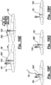
Images


Classifications
-
- E—FIXED CONSTRUCTIONS
- E21—EARTH OR ROCK DRILLING; MINING
- E21B—EARTH OR ROCK DRILLING; OBTAINING OIL, GAS, WATER, SOLUBLE OR MELTABLE MATERIALS OR A SLURRY OF MINERALS FROM WELLS
- E21B43/00—Methods or apparatus for obtaining oil, gas, water, soluble or meltable materials or a slurry of minerals from wells
- E21B43/01—Methods or apparatus for obtaining oil, gas, water, soluble or meltable materials or a slurry of minerals from wells specially adapted for obtaining from underwater installations
- E21B43/0107—Connecting of flow lines to offshore structures
-
- E—FIXED CONSTRUCTIONS
- E21—EARTH OR ROCK DRILLING; MINING
- E21B—EARTH OR ROCK DRILLING; OBTAINING OIL, GAS, WATER, SOLUBLE OR MELTABLE MATERIALS OR A SLURRY OF MINERALS FROM WELLS
- E21B43/00—Methods or apparatus for obtaining oil, gas, water, soluble or meltable materials or a slurry of minerals from wells
- E21B43/01—Methods or apparatus for obtaining oil, gas, water, soluble or meltable materials or a slurry of minerals from wells specially adapted for obtaining from underwater installations
- E21B43/0122—Collecting oil or the like from a submerged leakage
-
- B—PERFORMING OPERATIONS; TRANSPORTING
- B63—SHIPS OR OTHER WATERBORNE VESSELS; RELATED EQUIPMENT
- B63C—LAUNCHING, HAULING-OUT, OR DRY-DOCKING OF VESSELS; LIFE-SAVING IN WATER; EQUIPMENT FOR DWELLING OR WORKING UNDER WATER; MEANS FOR SALVAGING OR SEARCHING FOR UNDERWATER OBJECTS
- B63C7/00—Salvaging of disabled, stranded, or sunken vessels; Salvaging of vessel parts or furnishings, e.g. of safes; Salvaging of other underwater objects
- B63C7/006—Emptying the contents of sunken, stranded, or disabled vessels, e.g. by engaging the vessel; Underwater collecting of buoyant contents, such as liquid, particulate or gaseous contents, escaping from sunken vessels, e.g. using funnels, or tents for recovery of escaping hydrocarbons
-
- B—PERFORMING OPERATIONS; TRANSPORTING
- B65—CONVEYING; PACKING; STORING; HANDLING THIN OR FILAMENTARY MATERIAL
- B65D—CONTAINERS FOR STORAGE OR TRANSPORT OF ARTICLES OR MATERIALS, e.g. BAGS, BARRELS, BOTTLES, BOXES, CANS, CARTONS, CRATES, DRUMS, JARS, TANKS, HOPPERS, FORWARDING CONTAINERS; ACCESSORIES, CLOSURES, OR FITTINGS THEREFOR; PACKAGING ELEMENTS; PACKAGES
- B65D88/00—Large containers
- B65D88/78—Large containers for use in or under water
-
- E—FIXED CONSTRUCTIONS
- E21—EARTH OR ROCK DRILLING; MINING
- E21B—EARTH OR ROCK DRILLING; OBTAINING OIL, GAS, WATER, SOLUBLE OR MELTABLE MATERIALS OR A SLURRY OF MINERALS FROM WELLS
- E21B43/00—Methods or apparatus for obtaining oil, gas, water, soluble or meltable materials or a slurry of minerals from wells
- E21B43/01—Methods or apparatus for obtaining oil, gas, water, soluble or meltable materials or a slurry of minerals from wells specially adapted for obtaining from underwater installations
- E21B43/017—Production satellite stations, i.e. underwater installations comprising a plurality of satellite well heads connected to a central station
-
- E—FIXED CONSTRUCTIONS
- E02—HYDRAULIC ENGINEERING; FOUNDATIONS; SOIL SHIFTING
- E02B—HYDRAULIC ENGINEERING
- E02B17/00—Artificial islands mounted on piles or like supports, e.g. platforms on raisable legs or offshore constructions; Construction methods therefor
- E02B2017/0056—Platforms with supporting legs
- E02B2017/0069—Gravity structures
-
- E—FIXED CONSTRUCTIONS
- E02—HYDRAULIC ENGINEERING; FOUNDATIONS; SOIL SHIFTING
- E02B—HYDRAULIC ENGINEERING
- E02B17/00—Artificial islands mounted on piles or like supports, e.g. platforms on raisable legs or offshore constructions; Construction methods therefor
- E02B2017/0056—Platforms with supporting legs
- E02B2017/0073—Details of sea bottom engaging footing
- E02B2017/0086—Large footings connecting several legs or serving as a reservoir for the storage of oil or gas
Definitions
- the present disclosure relates to a method and apparatus for access and remediation of hydrocarbon storage tanks, and in particular to a method and apparatus for the removal of hydrocarbon fluids from subsea storage tanks associated with offshore installations in the hydrocarbon exploration and production industry. Aspects of the disclosure relate to methods used in the abandonment and/or decommissioning of offshore hydrocarbon production installations. The disclosure also relates to equipment used in abandonment and/or decommissioning applications.
- FIG. 1 A and 1 B show schematically a Gravity Base Structure of the type found in the North Sea.
- the Gravity Base Structure shown generally at 1 , comprises a number of storage cells 2 that stand on the seabed.
- the storage cells 2 are formed from steel reinforced, pre-stressed concrete, and are substantially cylindrical and arranged in a honeycomb formation. In this example, three cells extend in to legs 3 which support the top sides 4 of the platforms. The remaining sixteen cells are used for oil/water separation and oil storage.
- the cells 2 have an approximate outer diameter of around 20 meters, and are approximately 61 meters high. At the upper end, each cell has an elliptical domed surface.
- the cells are flooded and held at a lower internal pressure which is lower than the seawater ambient pressure. This keeps the concrete forming the cells in compression.
- the pressure inside the cells is 4 bar (approximately 59 Psi) below the seawater ambient pressure.
- Figure 2 is a sectional view through cell number nineteen and leg number one of the GBS of Figures 1A and 1 B .
- the leg 2 comprises a cell draw down system 5 which functions to introduce fluids into the internal volume of the storage cell via a flowline 6, and an extraction system 7 for removal of hydrocarbons. Ballast sand 8a and sediments 8b are present in the bottom of the cell volume.
- a volume of oil 9 is present at the top of the cell volume above the relatively high density seawater and it is necessary to remove this so-called attic oil from the cell volume prior to removal of the cell.
- EP2106514A2 discloses a method and apparatus for securing a conduit to relatively inaccessible structures, for example, oil tanks on submerged ships.
- the method involves providing a conduit with a neck, temporarily securing the conduit to the surface, for example by means of magnets, etc, drilling a hole through the structure and passing the neck of the conduit through the hole in the structure, and passing an expander device through the neck of the conduit through the hole in the structure to widen a portion of the internal passage of the conduit in the region of the neck.
- an anchor hub for providing an access point in a capping plate of a hydrocarbon storage cell, the anchor hub comprising: a main body comprising an upper opening, a lower opening and a throughbore extending between the upper and lower openings, the main body comprising a lower portion configured to be located in and extend into a blind hole formed in an upper surface of the capping plate;
- the anchor hub comprises an upper portion which is upstanding from an upper surface of the capping plate.
- the upper portion may provide the attachment point for an item of process or flow equipment.
- the anchor hub may comprise a seal between an upper portion of the anchor hub and an upper surface of the capping plate.
- the anchor hub may comprise an upper connector, which may be a connector for a valve manifold.
- the throughbore of the anchor hub comprises a seat for a sealing plug.
- the throughbore of the anchor hub enables the passage of a drilling apparatus through the anchor hub, operable to drill through the blind hole and penetrate the capping plate.
- the one or more anchor ring assemblies may comprise a plurality of segments, which together form a ring disposed around a lower portion of the body.
- the anchor hub comprises a pair of anchor ring assemblies axially separated on the main body.
- the pair of anchor ring assemblies may be connected via a plurality of bolts.
- the bolts may be tensioning bolts, and may be designed to be tightened to bring the anchor ring assemblies towards one another in an axial direction of the hub.
- the one or more anchor ring assemblies may comprise a tapered profile, which may correspond to a tapered profile of the main body. Relative axial movement of an anchor ring assembly with respect to the main body may result in radial displacement of the anchoring ring.
- apparatus for accessing a hydrocarbon storage cell comprising an anchor hub as described above, and a valve manifold attachable to the attachment point of the anchor hub such that the valve manifold is in communication with the throughbore of the anchor hub.
- valve manifold comprises:
- the valve manifold preferably comprises a throughbore with sufficient to receive a drilling tool, and may comprise a seat for a drilling apparatus.
- the valve manifold may comprise an upper connector configured for connection to a drilling apparatus.
- the at least one isolation valve is operable to be actuated by an ROV torque bucket.
- the at least one isolation valve is operable to be actuated by a diver.
- the valve manifold comprises upper and lower isolation valves in the throughbore of the apparatus.
- the valve manifold may comprise a flow port or flow conduit which is in fluid communication with the throughbore between the upper and lower isolation valves.
- the flow port or conduit may be coupled to a third isolation valve in a flow line.
- the present disclosure also provides a subsea installation comprising:
- the subsea installation may comprise a valve manifold connected to the anchor hub.
- the present disclosure also provides a drilling apparatus for use with the anchor hub described above.
- the drilling apparatus comprises:
- the drilling apparatus may comprise a carriage configured to move axially within the internal volume defined by the support elements with the drill shaft and drill bit.
- the drilling apparatus may comprise a torque reaction block, the torque reaction block configured to be rotationally keyed with the support frame.
- the torque reaction block may be axially movable with respect to the support frame, and may be integral, or may be unitary, with the carriage.
- the torque reaction block comprises a plurality of recesses, and the recesses may be shaped and positioned to locate the support elements.
- the drilling apparatus comprises a lower bearing assembly, which may be configured to permit rotation and axial movement of the drill shaft.
- the drilling apparatus may comprise a centraliser, which may be disposed at the lower bearing assembly.
- the centraliser may comprise a sacrificial material.
- the drilling apparatus may comprise a seat configured to prevent downward movement of the drill shaft and drill bit beyond a predetermined distance.
- the seat may be configured to receive the carriage.
- the seat and the carriage may be configured to locate together to form a seal.
- the seat and/or the carriage may be provided with sealing elements.
- the support frame is open, and it may provide flow spaces for fluid to flow freely between the internal volume and a volume outside of the support frame.
- the drill shaft may be at least partially hollow.
- the drilling apparatus may provide a fluid circulation through the drill shaft and/or drill bit.
- Figures 1A , 1 B and 2 are representative of a drilling rig with a hydrocarbon storage facility to which the anchor hub of the present invention may be applied.
- a primary objective of the invention is to provide equipment for the safe and cost-effective access of a hydrocarbon storage cell, to facilitate remediation of attic oil from the cell, and accordingly, exemplary embodiments of the invention will be described in that context.
- the anchor hub may provide an attachment point for an item of equipment, on a surface of a concrete structure of an offshore installation, including but not limited to a leg or foundation.
- FIG 3 shows schematically an overview of equipment 100 used to form an opening in a subsea hydrocarbon storage cell.
- the equipment comprises an anchor hub 60 shown in a loose condition 60A and a tightened condition 60B respectively.
- the equipment also comprises a valve manifold 70, configured to be connected to the anchor hub 60, and a drilling tool 80, configured for attachment on an upper coupling of the valve manifold 70.
- the drilling tool is shown in a first condition 80A in which the internal drill components are retracted and a second condition 80B, in which the internal drilling components are extended.
- the equipment shown in Figure 3 is designed to provide an isolated attachment and access point for safe and efficient penetration of a hydrocarbon storage cell, and subsequent remediation or disposal of hydrocarbons.
- An overview of an access method will be described with reference to Figures 4A to 4F and the subsequent drawings which show equipment details.
- ROV Remotely Operated Vehicle
- This example method will be described in the context of a Remotely Operated Vehicle (ROV) -based operation; in other words one which predominantly uses ROVs to carry out subsea operations with reduced and/or minimal diver support.
- ROV Remotely Operated Vehicle
- Such operations take place in relatively deep water; in sea conditions which diver operations are undesirable; or over extended periods which may be unsuitable for diver-based work.
- alternative embodiments of the invention may have an increased reliance on diver-based operations, as will be clear from the following description.
- FIG. 4A shows schematically an initial stage of a storage cell access operation.
- Storage cell generally shown at 400, comprises a main wall and a domed upper surface 402 with a central opening 404.
- the opening is filled with a prefabricated concrete slab 406, and a capping plate 408 fills the opening and extends outwards over the wall of the domed surface 402 of the cell.
- the capping plate is formed from concrete, and is approximately 90cm to 120cm thick.
- the upper surface 410 of the capping plate 408 has a rough hand-tamped finish, and over the lifetime of the storage cell, debris and marine fouling has accumulated on the surface.
- a work-class ROV 102 is deployed to the storage cell 400 and is used to clean the upper surface of the capping plate 408.
- the cleaning is carried out by the jetting of high pressure seawater to the surface of the capping plate to remove debris and accumulated material such as drill cuttings.
- the apparatus 50 comprises a gravity base 52 which supports the apparatus on the capping plate 408, and a pillar 54 extending upwardly from the gravity base 52 and supporting the drilling components.
- the gravity base 52 comprises a central aperture 55 for extension of the drilling components through the gravity base, and a number of integrated pegs with dedicated hydraulic motors (neither being shown) in the gravity base 52 to retain the apparatus in position on the concrete cap.
- the drilling components of the apparatus 50 comprise a drill motor 56, drill shaft 57 and core bit 58, which are supported over the central aperture 55 aligned in parallel with the pillar by a pair of laterally extending swing arms 59.
- Drilling operations may be carried out via the work class ROV 102, which provides a source of hydraulic power for the drilling apparatus.
- the core bit 58 is a cylindrical sleeve comprising at its lower end 51 cutting serrations which, when the bit is rotated by the drill motor via the drill shaft and when down weight is applied, penetrate the surface of the concrete cap to drill out an annular recess to the penetrating depth of the bit.
- a formation 53 at the distal end of the core bit functions as a core catcher to engage the concrete, enabling it to break a concrete plug from the surrounding capping plate, which can then be retrieved by upward movement of the drilling components to leave a blind hole 412 in the capping plate.
- Figure 4C shows the drilling apparatus 50 on the capping plate, having removed a concrete plug using the drilling apparatus 50 in the manner described above.
- FIG. 4D The next stage of the operation, shown most clearly in Figure 4D , is the installation of an anchor hub 60 into the blind hole 412 of the capping plate.
- the anchor hub of this embodiment of the invention is shown most clearly in Figures 6A and 6B .
- the anchor hub 60 comprises a substantially cylindrical body 61 having an upper portion 62 and a lower portion 63.
- the upper portion 62 is formed to an outer diameter which is greater than the outer diameter of the lower portion 63.
- the lower portion is sized to be received in the blind hole 412 in the capping plate, whereas the upper portion is designed to be upstanding from the surface 410 of the capping plate to provide an attachment point for additional equipment.
- a shoulder 64 is defined at a lower edge of the upper portion 62 and provides an abutment surface for the surface 410 of the capping plate.
- the anchor hub 60 comprises a central throughbore 65 which extends through the upper and lower portions. Partway along the throughbore, the inner diameter is reduced from a relatively large inner diameter to a relatively smaller inner diameter. The transition between the large and small inner diameter proportions defines a seat 66 for equipment inserted into the anchor hub during use. Inwardly protruding locking members 67 are located in the lower portion below the seat 66, and provides a second locating formation for landing and/or locking equipment inserted into the hub during use.
- the outer surface of the anchor hub is also provided with an annular locating groove 611 for the attachment of additional equipment in use.
- the upper portion 62 of the anchor hub defines an annular body through which are formed a plurality of circumferentially-distributed holes 68 which provide access for anchoring bolts 69.
- the anchoring bolts are oriented longitudinally and parallel to the axis of the hub, and are distributed around the exterior of outer surface of the lower portion of the hub.
- the anchoring bolts 69 extend between and connect upper anchoring ring assembly 602 and lower anchoring ring assembly 603.
- the upper and lower anchoring ring assemblies are axially separated on the lower portion of the anchor hub.
- the lower anchoring ring assembly 603 is substantially annular and is located around the lower portion 63 at a lower end 605 of the anchor hub.
- Upper anchoring ring assembly 602 is substantially annular and is located around the lower portion at an axial position between the upper portion 62 and the lower anchoring ring assembly 603.
- Each of the upper and lower anchoring ring assemblies is formed from a number of part annular segments, which together form a split annular ring.
- the number of part-annular segments corresponds to the number of anchor bolts 69 (which in this case is eight).
- Each of the upper and lower anchoring ring assemblies 602, 603 has a tapered or conical profile which corresponds with an outer surface profile of the lower portion of the anchor hub at the point at which it is mounted.
- the inner surface of the anchoring ring is shaped such that the inner diameter decreases moving from an upper end 604 of the anchor hub to a lower end 605 of the anchor hub.
- the inner surface of the lower anchoring ring therefore has the shape of the inner surface of a truncated cone.
- the corresponding shape on the lower portion 63 of the main body is an outer diameter which decreases moving in a direction from the upper end of the anchor hub to the lower end of the anchor hub.
- the upper anchoring ring 602 has an inner surface profile which has an inner diameter which increases in a direction from the upper end 604 of the anchor hub to the lower end 605 of the anchor hub.
- the corresponding profile on the lower portion of the main body has an increased outer diameter moving from an upper end of the anchor hub to a lower end of the anchor hub.
- the segments of the upper and lower ring assemblies therefore each function as cooperating wedges, joined by the anchoring bolts.
- Outer surface of the lower and upper anchoring rings are provided with arrangements of axially distributed ridges 606, 607.
- the sealing arrangement comprises a compressible elastomeric material 609, which is oversized, and which in use is compressed to provide a seal between the anchor hub 60 and the hole in which it is located. It will be appreciated that a wide range of sealing configurations may be used within the scope of the invention.
- the anchor hub is also provided with a port 610 which provides fluid communication between the internal throughbore 65of the anchor hub and the seal arrangement. The port enables a liquid sealant to be pumped from the throughbore into the sealing arrangement to enhance the seal.
- the anchor hub 60 is located in the blind hole 412 in the capping plate 408. Conveniently, this can be achieved by using the gravity base and support pillar of the drilling apparatus 50.
- a second set of swinging support arms (not shown) may support the anchor hub 60 off-axis from the bore, and when the drilling phase is complete, the drilling components can be swung away from the bore axis, before the support arms for the anchor hub 60 are swung into place over the bore axis to lower the anchor hub into the bore. It will be appreciated that in alternative embodiments, other mechanisms may be used for lowering the anchor hub into the bore.
- the anchor hub 60 With the anchor hub 60 in the bore, in the position shown in Figure 3 , the lower end of the hub supports the weight of the hub, the upper and lower anchoring ring assemblies 602, 603 are axially separated and the shoulder 64 defined at the lower edge of the upper portion 62 is upstanding from the surface of the concrete cap.
- the drilling apparatus 50 (if used) is removed by recovery to surface using a recovery line and the assistance of a ROV.
- the anchoring bolts 69 are then sequentially tightened by accessing the bolts through the holes 68 in the upper portion 62.
- the tightening of the bolts brings the upper and lower anchoring rings axially closer together, causing the separate ring segments to ride up on the corresponding tapered profile of the lower member 63.
- the anchoring ring elements therefore move radially outwards to engage with the wall of the blind hole 412 and anchor the hub 60 in position.
- Axial movement of the upper and lower rings also causes compression of the elastomeric seal elements 609.
- Figure 6B is a section through the anchor hub in a tightened and anchored condition with the seal elements compressed.
- port 610 could be used to pump additional liquid sealant into the sealing arrangement 608.
- sealant material could be provided at the base of the throughbore 650 in the anchor hub, to seal between the lower end 605 of the hub and the bottom of the hole 412.
- the upper portion of the anchor provides an attachment point with a connector 612 for additional equipment as now will be described.
- the next stage in the access operation is the location and installation of the valve manifold 70 onto the anchor hub.
- the valve manifold 70 is deployed from surface and landed on the anchor hub 60 with the assistance of a work class ROV 102.
- FIG. 7 shows the features of the valve manifold 70 in more detail.
- the valve manifold of this embodiment is configured as a double block isolation valve arrangement.
- a lower connector 702 is configured to be mounted on the connector 612 defined by the upper portion 62 of the anchor hub 60.
- the lower connector 702 comprises a dog and window locking arrangement, in which an ROV (not shown) is operated to raise or lower the locking dogs to enable ball bearings to extend into or be retracted from the annular groove 611 on the anchor hub connector 612.
- An upper male connector 704 is provided for the connection of additional equipment.
- the upper connector 704 is identical to the connector 612 defined by the upper portion 62 of the anchoring hub.
- a longitudinal throughbore 706 extends between the upper and lower connectors.
- upper and lower isolation valves 708, 710 which in this embodiment are ball valves configured to be actuated by ROV torque buckets 712.
- Located between the upper and lower valves is a port 714 which is configured to be connected to a flowline 716 via an ROV operated isolation valve 718 and an optional check valve 720.
- the valve manifold With the upper and lower isolation valves 708, 710 open, the valve manifold provides full bore access to the anchoring hub 60. This facilitates intervention through the valve manifold 70, for example to insert a macerator, agitator, or pump into the storage cell to facilitate removal of materials.
- the port 714 is used to pressure test each of the isolation valves via a hot stab operated from the ROV.
- drilling tool 80 which is lowered from the surface and again landed with the assistance of a ROV, as shown in Figure 4E .
- the drilling tool 80 will be described in more detail with reference to Figures 8A and 8B .
- the drilling components of the tool may be free to drop under their own weight to the lower position as shown in Figure 8B , or may be retained in the upper position shown in Figure 8A .
- the drilling tool 80 comprises a drill shaft 802 coupled to a drill bit and a drill support frame 804.
- the drill bit is a conventional core bit comprising a core catcher at its lower end.
- a lower connector 806, which is of the same type as the connector 702 on the valve manifold 70, and is designed to be connected to the upper connector 704 of the manifold.
- the lower connector 806 comprises a dog and window locking arrangement to secure the drilling tool 80 on the valve manifold.
- a tie 816 supports four drill support bars 818 which extend from the lower connector 806 to the tie 816.
- the tie 816 retains the support bars 818 in a position which defines a central bore through which the drill shaft 802 moves between extended and retracted positions.
- the support frame 804 also comprises an intermediate tie 817 with joins the support bars on their exterior.
- a bearing assembly 810 which enables the drill shaft to be freely rotated in the drill support frame.
- a seat 812 which is configured to receive a carriage 814 of the drilling components.
- a centraliser 808 which is received in the bore defined by the valve manifold connector 704, and defines a throughbore for the passage of the drill shaft 802.
- the centraliser is a sleeve formed from a sacrificial material, such as a plastic, which facilitates longitudinal alignment of the drill during the early stages of drilling, but which may be damaged during the course of drilling.
- the drilling tool carriage 814 is shaped to be accommodated within the drill support frame 804, and comprises recesses (not shown) arranged around the outer surface of a torque reaction block 822.
- the recesses correspond to the position and profile of the support bars 818.
- the carriage 814 supports and carries a hydraulic drill motor 824, which is powered by a hydraulic hose 826 that runs out of the drilling tool behind the drill motor and carriage.
- the carriage 814 is able to slide with respect to the support bars, but due to interaction of the block and the bars, is rotationally keyed with respect to the support frame.
- ports 828 Disposed between the drill shaft 802 and the torque reaction block 822 is an arrangement of ports 828 which provides through connection through an interior of the drill shaft and the open space between the support bars.
- a lower surface of the carriage 814 is provided with a seal 830 for sealing the carriage 814 against the seat 812 when in a lowered position.
- the drilling operation proceeds as follows. With the drilling tool 80 located on the valve manifold block 70 , and the first and second isolation valves 708, 710 fully open, the drill shaft 802 extends into the valve manifold block and into the blind hole 412 to the base of the blind hole. Valve 718 is opened, and a vacuum is drawn on the port 714 by a pump (not shown) powered from surface or a local ROV, causing circulation of seawater through the open structure of the drill support frame 804, and into the hollow drill shaft 802 via the ports 828, and out of the port 714 to be returned to the sea.
- the hydraulic drill motor 824 is powered from surface or a local ROV to cause the drill shaft 802 and bit to rotate.
- the weight of the drill shaft in conjunction with the low pressure drawn through the valve 718, provides sufficient weight-on-bit to progress the drilling of a hole through the base of the blind hole.
- the carriage 814 slides downwards on the support bars, carrying with it the drill motor 824 and the distal end of the hydraulic hose 826 as the drill bit progresses through the concrete capping plate.
- a pressure differential between the hydrostatic pressure and the storage cell pressure causes the drill shaft 802 and carriage 814 to be drawn downwards until the lower surface of the carriage engages with the seat 812 and seals the ports 828, preventing further inflow of seawater.
- Valve 718 is closed to prevent inflow of seawater through the port 714.
- valve 718 is vented to partially pressure balance the system and ease the pulling of the drill shaft 802 and carriage 814 against the seal with the seat 812. With the carriage fully retracted, it is latched against the support frame (latch not shown) and the isolation valves 708, 710 in the valve manifold block are closed.
- the port 714 enables pressure testing of the valve manifold block, and optionally the valve manifold can be flushed by liquid or gas to remove any hydrocarbons from the flow lines. The drilling tool may then be decoupled from the valve manifold block and retrieved to surface.
- the drilling tool 80 has a number of benefits in the envisaged applications to the penetration and/or access of a hydrocarbon storage cell. Firstly, by adopting a staged process of forming a blind hole and a secondary penetrating bore, the penetration distance required by the drill 80 is relatively low. This enables the use of a compact and relatively lightweight drilling tool. This is in contrast with a conventional drilling approach which would require the use of heavy drilling equipment, deployed to and supported by the upper surface of the storage cell.
- the two stage process may also enable performance of the operation on multiple storage cells at convenient times. For example, multiple blind holes may be sequentially formed on adjacent storage cells during one phase of operation, prior to penetration drilling being carried out in a second phase. This facilitates optimal use of resources. This is in contrast with convention single stage drilling, which may take a considerable amount of time from start to finish with no convenient point to pause or interrupt the operation.
- a secure, sealed attachment point for isolation and process equipment is provided.
- this equipment is not required to seal against the relatively coarse upper surface of the capping plate. To do so would require a time-consuming and technically challenging surface polishing operation, so that the surface is sufficiently smooth to enable drilling equipment to be sealed on the surface.
- the drilling support frame is designed to provide sufficient support to the drilling equipment, but remaining weak enough to be distorted or damaged if impacted during use, for example by a ROV or another subsea object or item of mobile infrastructure. This prevents large forces being transferred to the valve manifold and/or capping plate of the storage cell.
- the foregoing description relates to a method of providing penetration and access to a hydrocarbon storage cell, and results in the provision of an access point in the form of an anchor hub 60 and an isolation valve manifold 70.
- the valve manifold provides a connection point for a hose connector to enable hydrocarbons to be transferred from and/or to the storage cell during a remediation operation.
- FIG. 9 An example of such a hose connector assembly is shown in Figure 9 , generally at 90.
- the hose connector assembly 90 comprises a lower connector 91, which is of the dog and window locking type described above in the context of the valve manifold and the drilling tool.
- the hose connector assembly comprises a T-piece 92 defining a throughbore 95 between the lower connector 91 and an upper flange plate 93.
- a blind flange 94 is joined to the flange plate to close the throughbore.
- a side arm 96 of the T-piece 92 comprises a side bore 97 to a side flange 98.
- a receptacle 99 of a hot stab connector 107 Joined to the side flange 98 is a receptacle 99 of a hot stab connector 107, which enables the coupling of a transfer hose 108 with the hose connector assembly 90.
- the hose connector assembly 90 is configured for attachment to a vertically oriented hot stab, which has an elbow joint for connection to a horizontally-oriented hose.
- the configuration of the hose connector assembly 90 also enables convenient coupling of a hose to the valve manifold while maintaining full bore access to the manifold via the throughbore 95 if required. This facilitates intervention through the valve manifold 70, for example to insert a macerator, agitator, or pump into the storage cell to facilitate removal of materials, optionally while a hose is connected.
- FIG. 10 of the drawings An alternative hose connector assembly is shown in Figure 10 of the drawings, generally depicted at 101, and configured for attachment to a horizontally-oriented hot stab for in-line or on-axis connection to a horizontally-oriented hose.
- the hose connector assembly 101 comprises a lower connector 103, which is of the dog and window locking type described above in the context of the valve manifold and the drilling tool.
- the hose connector assembly lacks a T-piece, and instead defines an axial throughbore 104 between the lower connector 91 and an upper flange plate 105.
- Joined to the upper flange plate 105 is a receptacle 106 of a hot stab connector 107, which enables the coupling of a transfer hose 108 with the hose connector assembly 100.
- anchor hubs may be used in different embodiments of the invention. Examples of anchor hubs in different forms are shown in Figures 4 to 11 .
- the anchor hub 110 is similar to the anchor hub 60, and will be understood from Figures 6A and 6B and the accompanying description.
- the anchor hub 110 comprises upper and lower rings 111, 112 with inner tapered surfaces which correspond to tapered surfaces on the outer surface of the main hub body 114.
- the rings 111, 112 are brought together by the tightening of anchor bolts, and compress an intermediate seal arrangement 116.
- the anchor hub 110 differs from the hub 60 of Figure 6 in that the upper portion 117 of the anchor hub comprises a J lock spigot 118 for mounting equipment, such as a valve manifold, on the concrete capping plate.
- FIG 12 is a sectional view through an anchor hub according to an alternative embodiment of the invention, generally shown at 120.
- This embodiment is again similar to the anchor hubs 60 and 110 of Figures 6 and 11 in that it has an arrangement of corresponding tapered profiles.
- this embodiment differs in that the upper and lower tapered rings 121, 122 are solid rings, and a segmented anchor ring 123 is arranged around the exterior of the main body 124 of the anchor and rings 121, 122.
- the anchor hub 120 is internally actuated by a threaded engagement of the main body with the lower anchor ring 122. This causes the lower anchor ring to move axially upwards and forces the external anchor ring 123 to engage the bore.
- the upper portion of the anchor hub provides a flange attachment.
- FIG 13 is a sectional view through an anchor hub 130 according to a further alternative embodiment of the invention.
- the anchor hub is formed from the core drill bit itself, which is retained in the concrete capping plate.
- the anchor comprises a hollow cylinder 131 which forms an annular groove during drilling.
- the upper part of the anchor hub is provided with a J lock spigot 132 for mounting equipment, such as a valve manifold.
- a resin is pumped into the micro-annulus between the core bit and the concrete capping plate in order to seal between the lower end of the sleeve and the plate.
- This configuration has the advantage of fewer operation steps in order to mount the hub, but does require drilling through the full thickness of the capping plate in the subsequent drilling operation in order to penetrate the storage cell.
- FIG 14 is a sectional view through an anchor hub 140 according to a further alternative embodiment of the invention.
- the anchor hub is mounted into a blind hole.
- the main body 141 of the hub is externally bolted to the capping plate via a flange 142.
- Sealing elements 143, 144 are provided beneath the flange plate and surrounding the lower portion of the anchor in axially separated positions.
- the upper portion of the anchor hub is provided with a J lock spigot 145 for the mounting of equipment, such as a valve manifold.
- Figure 15A shows the top of a second storage cell 1500, which has an anchor hub 110 installed in a blind hole in a capping plate 1508.
- the storage cell 1500 is the same as the storage cell 400, and the blind hole is formed by the method described with reference to Figures 4B and 4C .
- the anchor hub 110 in this example is the anchor hub 110 of Figure 11 , and as shown in Figure 15A has been fixed into the capping plate to provide access and attachment point.
- FIG 15B shows a valve manifold 1600 and drilling tool 180 deployed from surface and landed with the assistance of ROV 102.
- the valve manifold 1600 is shown in more detail in Figure 16 .
- the manifold comprises a main body 1602, and a lower connector 1604, which in this case is configured for attachment to a J lock spigot of the anchor hub 110.
- a throughbore 1606 extends from the lower connector 1604 to an upper opening 1608, which includes a guide funnel 1610 for assisting with the placement of the drilling apparatus 180 in the manifold 1600.
- an isolation valve 1612 which in this case is a ball valve operable to be actuated by a ROV torque bucket 1614.
- a seat 1615 defined by a reduced inner diameter.
- the seat provides a landing point for the drilling tool 180 and a sealing plug running tool.
- a side conduit 1616 Disposed between the isolation valve 1612 and the lower connector 1604 is a side conduit 1616 which extends from the throughbore 1606 to a side flange 1618.
- the side flange 1618 is configured for the attachment of a hot stab hose connection receptacle 1620, in this case in a vertical orientation, which enables a ROV to connect a hot stab of a transfer hose 108 to the valve manifold ( Figure 15B ).
- the valve manifold 1600 also provides a guide for the drilling tool 180 to drill a hole which penetrates the storage cell 1500.
- the drilling tool 180 is similar in form and function to the drilling tool 80 described in detailed reference to Figures 4E, 4F , 8A and 8B and will not be described in detail here.
- the drilling tool 180 differs in that a lower bearing assembly on the drilling support frame is configured to be received in the seat 1615.
- the lower bearing assembly of the drilling tool is located on the seat, and provides support and centralisation for passage and rotation of the drill shaft.
- the drilling tool 180 is operated to drill a hole through the base of the blind hole and into the storage cell.
- the method of drilling is similar to the method described with reference to Figures 4E, 4F , 8A and 8B and will not be described in detail here.
- the drilling of the penetrating hole is performed with the side conduit 1616 of the valve manifold 1600 connected to a storage cell 400 which has already been penetrated.
- the cell 1500 is to be remediated by transferring hydrocarbons contained in the storage cell 1500 to a disposal cell, which in this case is cell 400.
- Cell 400 has been provided with an anchor hub 60 and valve manifold 70 by the method described with reference to Figure 4 .
- Figure 15D shows schematically the equipment installed on the remediating cell 1500 and the disposal cell 400.
- the isolation valves 708 and 710 are opened to provide fluid communication between the internal volume of the storage cell 400 and the manifold 1600.
- the relatively low pressure of the cell 400 draws seawater through the open structure of the drill support frame, and into the hollow drill shaft via ports, and through the hose 108 to the disposal cell 400.
- the low pressure also causes the drill shaft and core bit of the drilling tool 180 causes the drill shaft and carriage to be drawn downwards until the lower surface of the carriage engages with a seat.
- the storage cell 1500 is now ready to be remediated.
- a transfer pump assembly 1520 On the valve manifold 70 of the disposal cell 400 is mounted a transfer pump assembly 1520.
- the pump assembly comprises a progressive cavity multiphase pump and a connector which corresponds to the upper connector 704 of the valve manifold.
- the pump assembly 1520 comprises a viewing window to enable a ROV (or diver) to monitor the fluid being pumped through the assembly.
- ROV or diver
- the low pressure on the inlet side of the pump 1520 causes hydrocarbons to be drawn from the remediating cell 1500 along the transfer hose and through the valve manifold 70 into the disposal cell 400.
- the ROV monitors the fluid being pumped through the pump assembly, until it is observed that seawater (rather than hydrocarbons) is being pumped through the transfer hose 108.
- the remediating cell is isolated, and the transfer hose is flushed into the disposal cell.
- the remediating cell valve manifold 1600 is pressure tested, and the hose connector is removed from the valve manifold, ready for transfer to another remediating cell.
- Figure 15E shows an optional step of injecting dispersible chemicals into the remediating cell via a second hose 109, which in this case is run from surface.
- FIG 15F shows a sealing plug and running tool assembly 1700 which is deployed from surface and landed with the assistance of the ROV 102.
- the sealing plug and running tool assembly 1700 is shown in more detail in Figure 17 .
- the running tool 1701 comprises a cylindrical sleeve 1702 with a lower seal assembly 1704, shaped and sized to fit into the seat 1615 defined by the valve manifold 1600.
- a shaft 1706 extends through the sleeve 1702 and the seal assembly 1704 to support a plug 1703 at its lower end.
- the sealing plug and running tool assembly 1700 is received in the upper part of the valve manifold 1600, and the lower seal assembly is landed on the seat.
- the seal is pressure tested, and subsequently the shaft 1706 is extended to mount the sealing plug 1703 in an upper part of the anchor hub 110.
- the equipment is again pressure tested, and the shaft 1706 is removed from the sealing plug 1703 to leave it in the anchor hub 110.
- the running tool 1701 is then recovered to surface through the valve manifold.
- valve manifold 1600 With the sealing plug 1703 in place, the valve manifold 1600 is removed from the anchor hub and recovered to surface. A blind cap is installed over the anchor hub, and optionally the anchor hub is capped with concrete to complete the plugging and capping operation. The storage cell 400 is then fully remediated.
- a hose may be deployed from surface and connected to the valve manifold of the disposal cell.
- a surface or subsea pump is operated to remove the attic oil from the disposal cell, before the hose is removed.
- the sealing and plugging operations described with reference to Figures 15F and 15G may then be repeated to plug and cap the remediated disposal cell.
- FIG 18 is an alternative example of a valve manifold, which is configured for diver-based operations.
- the valve manifold, generally shown at 1800 is similar to the valve manifold 70, and will be understood from Figure 7 and the accompanying description.
- the valve manifold 1800 is shown installed on an anchor hub, which is the anchor hub 120 described with reference to Figure 12 .
- the valve manifold 1800 comprises upper and lower isolation valves 1808, 1810, and an intermediate port 1814 coupled to an isolation valve 1818.
- valve manifold connectors which may be attached by the diver.
- the valves 1808, 1810 and 1818 function in a similar way to valves 704, 718 and 710, although are provided with manually actuated levers 1809, 1811, 1819 to facilitate diver-based operations.
- FIGS 19A to 19H there are shown sequentially the steps of installing an anchor hub on a storage cell, penetrating the storage cell, and remediating the storage cell.
- the sequence shown is similar to the sequences shown in Figures 4A to 4F and 15A to 15G , but differs in that they are primarily operated by divers.
- a diver 1901 operates the drilling apparatus 50 to form a blind hole in the capping plate 408.
- the diver installs a valve manifold 1800 on an anchor hub 120 in the blind hole.
- a drilling apparatus 80 is located in the valve manifold, and the diver performs the drilling operation to penetrate the storage cell.
- Figure 19E shows diver-supervised remediation of a storage cell 1501 to a disposal cell 401, the latter having a transfer pump assembly 1520 installed.
- the diver monitors the transfer of fluids through the transfer hose 108 via a viewing window provided in the hose connector assembly 1903.
- the invention provides an anchor hub for accessing a hydrocarbon storage cell and/or removing hydrocarbons therefrom.
- An access method comprises installing the anchor hub in a capping plate of the hydrocarbon storage cell, and drilling a bore to penetrate an internal volume of the storage cell by passing a drilling apparatus through the anchor hub.
- a removal method comprises providing a first hydrocarbon storage cell comprising a first anchor hub and providing a second hydrocarbon storage cell comprising a second anchor hub. The first and second anchor hubs are connected to one another with a flowline, and hydrocarbons are pumped from an upper portion of an internal volume of the second hydrocarbon storage cell to an internal volume of the first hydrocarbon storage cell.
- the anchor hub in one aspect of the invention comprises a main body comprising an upper opening, a lower opening and a throughbore extending between the upper and lower openings.
- the main body comprises a lower portion configured to be located in and extend into a blind hole formed in the capping plate.
- Securing means are configured to fix the lower portion of the anchor hub in the blind hole.
- An annular seal is arranged around the lower portion to provide a seal between the lower portion and the blind hole.
- An attachment point is provided for connecting an item of process or flow equipment to the anchor hub such that the item of process or flow equipment is in communication with the throughbore.
- the invention provides apparatus for accessing and/or removal of hydrocarbons from a storage cell in a manner that is safe, effective, convenient, and economical.
- the two stage access and penetration process enables performance of the operation on multiple storage cells at convenient times optimising use of resources.
- an anchor hub installed into a blind hole the capping plate in a first phase, a secure, sealed attachment point for isolation and process equipment is provided. Significantly, this equipment is not required to seal against the relatively coarse upper surface of the capping plate.
- the drilling support frame is designed to provide sufficient support to the drilling equipment, but prevents large forces being transferred to the valve manifold and/or capping plate of the storage cell.
Landscapes
- Engineering & Computer Science (AREA)
- Geology (AREA)
- Life Sciences & Earth Sciences (AREA)
- Mining & Mineral Resources (AREA)
- Geochemistry & Mineralogy (AREA)
- Fluid Mechanics (AREA)
- Environmental & Geological Engineering (AREA)
- General Life Sciences & Earth Sciences (AREA)
- Physics & Mathematics (AREA)
- Mechanical Engineering (AREA)
- Ocean & Marine Engineering (AREA)
- Chemical & Material Sciences (AREA)
- Oil, Petroleum & Natural Gas (AREA)
- Filling Or Discharging Of Gas Storage Vessels (AREA)
- Earth Drilling (AREA)
- Processing Of Stones Or Stones Resemblance Materials (AREA)
Claims (13)
- Anschlusselement (60, 110, 120, 140) zum Bereitstellen eines Zugriffspunkts in einer Abdeckplatte (408) einer Kohlenwasserstoff-Lagerzelle (2), wobei das Anschlusselement (60, 110, 120, 140) Folgendes umfasst:einen Hauptkörper (61), der eine obere Öffnung, eine untere Öffnung und eine Durchgangsbohrung (65) umfasst, die sich zwischen der oberen und der unteren Öffnung erstreckt, wobei der Hauptkörper einen unteren Abschnitt (63) umfasst, der dazu konfiguriert ist, sich in einem Blindloch (412) zu befinden und sich in dieses hinein zu erstrecken, das in einer oberen Oberfläche der Abdeckplatte (408) ausgebildet ist,ein Sicherungsmittel, das dazu konfiguriert ist, den unteren Abschnitt (63) des Anschlusselements (60, 110, 120, 140) in dem Blindloch (412) zu fixieren,eine ringförmige Dichtung (609, 116, 143, 144), die um den unteren Abschnitt herum angeordnet ist, um eine Abdichtung zwischen dem unteren Abschnitt (63) und dem Blindloch (412) bereitzustellen; undeinen Befestigungspunkt zum Verbinden eines Artikels der Prozess- oder Strömungsausrüstung mit dem Anschlusselement (60, 110, 120, 140), so dass der Artikel der Prozess- oder Strömungsausrüstung mit der Durchgangsbohrung (65) in Kommunikation steht;dadurch gekennzeichnet, dass das Sicherungsmittel eine oder mehrere Anschlussringanordnungen umfasst, die als Keile oder Pflöcke fungieren und so konfiguriert sind, dass eine relative axiale Bewegung einer Anschlussringanordnung in Bezug auf den Hauptkörper zum Eingriff eines Anschlussbestandteils mit dem Blindloch führt.
- Anschlusselement nach Anspruch 1, wobei die Durchgangsbohrung (65) des Anschlusselements (60, 110, 120, 140) den Durchgang einer Bohrvorrichtung (80, 180) durch das Anschlusselement (60, 110, 120, 140) ermöglicht, die dazu betreibbar ist, durch das Blindloch (412) zu bohren und die Abdeckplatte (408) zu durchdringen.
- Anschlusselement nach Anspruch 1 oder Anspruch 2, wobei das Anschlusselement einen oberen Abschnitt umfasst, der von einer oberen Oberfläche der Abdeckplatte nach oben steht.
- Anschlusselement nach Anspruch 3, wobei der obere Abschnitt den Befestigungspunkt für einen Artikel der Prozess- oder Strömungsausrüstung bereitstellt.
- Anschlusselement (60, 110, 120, 140) nach einem der Ansprüche 1 bis 4, ferner eine Dichtung zwischen einem oberen Abschnitt (62) des Anschlusselements (60, 110, 120, 140) und einer oberen Oberfläche der Abdeckplatte (408) umfassend.
- Anschlusselement (60, 110, 120, 140) nach einem der Ansprüche 1 bis 5, wobei der Befestigungspunkt einen oberen Verbinder (612, 118, 145) für einen Ventilblock (70, 1600, 1800) umfasst.
- Anschlusselement nach einem der Ansprüche 1 bis 6, wobei die Durchgangsbohrung des Anschlusselements eine Aufnahme für einen Dichtstopfen umfasst.
- Anschlusselement nach einem vorhergehenden Anspruch, wobei die eine oder mehreren Anschlussringanordnungen eine Vielzahl von Segmenten umfassen, die zusammen einen Ring bilden, der um den unteren Abschnitt des Körpers positioniert ist.
- Anschlusselement nach einem vorhergehenden Anspruch, wobei das Anschlusselement ein Paar Anschlussringanordnungen umfasst, die auf dem Hauptkörper axial voneinander getrennt sind.
- Anschlusselement nach Anspruch 9, wobei das Paar Anschlussringanordnungen über eine Vielzahl von Bolzen verbunden ist.
- Anschlusselement nach Anspruch 10, wobei die Bolzen Zugbolzen sind und so angeordnet sind, dass sie angezogen werden, um die Anschlussringanordnungen in einer axialen Richtung des Elements aufeinander zuzuführen.
- Anschlusselement nach einem vorhergehenden Anspruch, wobei die eine oder mehrere Anschlussringanordnungen ein konisches Profil umfassen, das einem konischen Profil des Hauptkörpers entspricht.
- Vorrichtung zum Zugreifen auf eine Kohlenwasserstoff-Lagerzelle, wobei die Vorrichtung ein Anschlusselement nach einem der Ansprüche 1 bis 12 und einen Ventilblock umfasst, der an dem Befestigungspunkt des Anschlusselements befestigbar ist, so dass der Ventilblock mit der Durchgangsbohrung des Anschlusselements in Kommunikation steht.
Applications Claiming Priority (3)
| Application Number | Priority Date | Filing Date | Title |
|---|---|---|---|
| GBGB1415031.2A GB201415031D0 (en) | 2014-08-25 | 2014-08-25 | Method and apparatus for access and remediation of hydrocarbon storage tanks |
| PCT/GB2015/052448 WO2016030670A2 (en) | 2014-08-25 | 2015-08-25 | Method and apparatus for access and remediation of hydrocarbon storage tanks |
| EP15771221.7A EP3186472B8 (de) | 2014-08-25 | 2015-08-25 | Verfahren und vorrichtung zum zugriff und zur sanierung von kohlenwasserstofflagertanks |
Related Parent Applications (2)
| Application Number | Title | Priority Date | Filing Date |
|---|---|---|---|
| EP15771221.7A Division EP3186472B8 (de) | 2014-08-25 | 2015-08-25 | Verfahren und vorrichtung zum zugriff und zur sanierung von kohlenwasserstofflagertanks |
| EP15771221.7A Division-Into EP3186472B8 (de) | 2014-08-25 | 2015-08-25 | Verfahren und vorrichtung zum zugriff und zur sanierung von kohlenwasserstofflagertanks |
Publications (2)
| Publication Number | Publication Date |
|---|---|
| EP3828376A1 EP3828376A1 (de) | 2021-06-02 |
| EP3828376B1 true EP3828376B1 (de) | 2024-12-11 |
Family
ID=51727011
Family Applications (2)
| Application Number | Title | Priority Date | Filing Date |
|---|---|---|---|
| EP20213482.1A Active EP3828376B1 (de) | 2014-08-25 | 2015-08-25 | Anschlusselement und vorrichtung für zugriff auf und sanierung von kohlenwasserstofflagertanks |
| EP15771221.7A Active EP3186472B8 (de) | 2014-08-25 | 2015-08-25 | Verfahren und vorrichtung zum zugriff und zur sanierung von kohlenwasserstofflagertanks |
Family Applications After (1)
| Application Number | Title | Priority Date | Filing Date |
|---|---|---|---|
| EP15771221.7A Active EP3186472B8 (de) | 2014-08-25 | 2015-08-25 | Verfahren und vorrichtung zum zugriff und zur sanierung von kohlenwasserstofflagertanks |
Country Status (5)
| Country | Link |
|---|---|
| EP (2) | EP3828376B1 (de) |
| CA (1) | CA2959106C (de) |
| DK (1) | DK3828376T3 (de) |
| GB (4) | GB201415031D0 (de) |
| WO (1) | WO2016030670A2 (de) |
Families Citing this family (1)
| Publication number | Priority date | Publication date | Assignee | Title |
|---|---|---|---|---|
| GB2581178B (en) | 2019-02-06 | 2022-06-08 | Sllp 134 Ltd | Gas storage system |
Citations (2)
| Publication number | Priority date | Publication date | Assignee | Title |
|---|---|---|---|---|
| EP2106514B1 (de) * | 2007-01-27 | 2011-08-17 | Deep Tek Underwater IP Limited | Verfahren und vorrichtung zur befestigung einer leitung an einer struktur |
| EP2039972B1 (de) * | 2007-08-24 | 2013-10-16 | Aerotechnik E. Siegwart GmbH | Dichtungsvorrichtung für eine Steckverbindung |
Family Cites Families (8)
| Publication number | Priority date | Publication date | Assignee | Title |
|---|---|---|---|---|
| FR2507997A1 (fr) * | 1981-06-17 | 1982-12-24 | Bretagne Atel Chantiers | Procede pour realiser le pompage d'un reservoir sombre contenant un hydrocarbure lourd et installation pour la mise en oeuvre du procede |
| US4556343A (en) * | 1984-02-10 | 1985-12-03 | Cheung Maxwell C | Offshore oil storage and transfer facility |
| GB9324560D0 (en) * | 1993-11-30 | 1994-01-19 | Framo Dev Uk Ltd | An apparatus for extraction of a fluent material from a container |
| JP4172560B2 (ja) * | 1998-12-28 | 2008-10-29 | 日本サルヴ▲ヱ▼ージ株式会社 | 液体物質回収方法、および液体物質回収装置 |
| FR2850631B1 (fr) * | 2003-01-31 | 2006-03-03 | Ifremer | Procede de recuperation d'une cargaison de liquides polluants a bord d'une epave |
| GB201103751D0 (en) * | 2011-03-07 | 2011-04-20 | Bamford Antony S | Flexible mixing and remediatin device deployed underwater for the clean up of concrete storage cells |
| WO2012149017A2 (en) * | 2011-04-26 | 2012-11-01 | Bp Corporation North America, Inc. | Subsea hydrocarbon containment apparatus |
| GB201218569D0 (en) * | 2012-10-16 | 2012-11-28 | Mojo Maritime Ltd | Improvements in or relating to marine operations |
-
2014
- 2014-08-25 GB GBGB1415031.2A patent/GB201415031D0/en not_active Ceased
-
2015
- 2015-08-25 EP EP20213482.1A patent/EP3828376B1/de active Active
- 2015-08-25 EP EP15771221.7A patent/EP3186472B8/de active Active
- 2015-08-25 CA CA2959106A patent/CA2959106C/en active Active
- 2015-08-25 GB GB1515083.2A patent/GB2533986B8/en active Active
- 2015-08-25 GB GB1709942.5A patent/GB2552887B/en active Active
- 2015-08-25 WO PCT/GB2015/052448 patent/WO2016030670A2/en not_active Ceased
- 2015-08-25 GB GB1816161.2A patent/GB2565663B/en active Active
- 2015-08-25 DK DK20213482.1T patent/DK3828376T3/da active
Patent Citations (2)
| Publication number | Priority date | Publication date | Assignee | Title |
|---|---|---|---|---|
| EP2106514B1 (de) * | 2007-01-27 | 2011-08-17 | Deep Tek Underwater IP Limited | Verfahren und vorrichtung zur befestigung einer leitung an einer struktur |
| EP2039972B1 (de) * | 2007-08-24 | 2013-10-16 | Aerotechnik E. Siegwart GmbH | Dichtungsvorrichtung für eine Steckverbindung |
Non-Patent Citations (2)
| Title |
|---|
| UNKNOWN: "Metadata", 6 October 2008 (2008-10-06), pages 1 - 1, XP093094764, Retrieved from the Internet <URL:http://www.parkerstore.jp/phj/catalog/pdf/english_ex/EFCG9_Industrial_Tube_Fittings_Adapters_and_Equipment-Cat_4300_EN/EFCG9_Tube_Fittings_4300_2_Seal-Lok_O-Ring_Face_Seal_Fittings.pdf> [retrieved on 20231025] * |
| UNKNOWN: "Seal-Lok (TM) O-Ring Face Seal Tube Fittings", 6 August 2008 (2008-08-06), pages 1 - 1, XP093094763, Retrieved from the Internet <URL:http://www.parkerstore.jp/phj/catalog/pdf/english_ex/EFCG9_Industrial_Tube_Fittings_Adapters_and_Equipment-Cat_4300_EN/EFCG9_Tube_Fittings_4300_2_Seal-Lok_O-Ring_Face_Seal_Fittings.pdf> [retrieved on 20231025] * |
Also Published As
| Publication number | Publication date |
|---|---|
| GB2552887B (en) | 2018-12-19 |
| GB2533986B (en) | 2017-09-13 |
| GB2565663A (en) | 2019-02-20 |
| GB2533986A (en) | 2016-07-13 |
| GB201515083D0 (en) | 2015-10-07 |
| GB201415031D0 (en) | 2014-10-08 |
| EP3828376A1 (de) | 2021-06-02 |
| GB2552887A (en) | 2018-02-14 |
| EP3186472B1 (de) | 2021-10-27 |
| DK3828376T3 (da) | 2025-01-13 |
| GB201709942D0 (en) | 2017-08-02 |
| WO2016030670A2 (en) | 2016-03-03 |
| CA2959106C (en) | 2023-02-21 |
| GB2533986B8 (en) | 2017-10-25 |
| GB2565663B (en) | 2019-05-15 |
| WO2016030670A3 (en) | 2016-06-16 |
| EP3186472A2 (de) | 2017-07-05 |
| EP3186472B8 (de) | 2021-12-01 |
| CA2959106A1 (en) | 2016-03-03 |
Similar Documents
| Publication | Publication Date | Title |
|---|---|---|
| EP2900897B1 (de) | Bohrsystem mit druckverwaltung und bohrlochkontrollverfahren | |
| US9702211B2 (en) | Method and an apparatus for retrieving a tubing from a well | |
| CN105735251B (zh) | 桥梁桩基旋挖钻机切削式全护筒跟进成桩施工方法及系统 | |
| CA2967933C (en) | Subsea slanted wellhead system and bop system with dual injector head units | |
| NO325322B1 (no) | Injeksjonsrorelement for a injisere et fluid mellom mantler | |
| BR102014028614A2 (pt) | sistema de liberação de esfera, conjunto de instalação de revestimento e método para suspender uma coluna tubular interna a partir de uma coluna tubular externa | |
| WO2013167872A2 (en) | Drilling and lining subsea wellbores | |
| MXPA01003767A (es) | Metodo de perforacion. | |
| NO20101583A1 (no) | Fremgangsmate og anordning for a etablere et borehull i sjobunnen. | |
| US9109406B2 (en) | Method for removing a hydrocarbon production platform from sea | |
| EP3828376B1 (de) | Anschlusselement und vorrichtung für zugriff auf und sanierung von kohlenwasserstofflagertanks | |
| US20100307768A1 (en) | Downhole Tubular Lifter and Method of Using the Same | |
| AU2009233524B8 (en) | Method of creating an underwater cutting zone, and related plugging devices and methods | |
| US9856716B2 (en) | Pressure release assembly for casing of drilling rig | |
| US20180171722A1 (en) | Well drilling system |
Legal Events
| Date | Code | Title | Description |
|---|---|---|---|
| PUAI | Public reference made under article 153(3) epc to a published international application that has entered the european phase |
Free format text: ORIGINAL CODE: 0009012 |
|
| STAA | Information on the status of an ep patent application or granted ep patent |
Free format text: STATUS: THE APPLICATION HAS BEEN PUBLISHED |
|
| AC | Divisional application: reference to earlier application |
Ref document number: 3186472 Country of ref document: EP Kind code of ref document: P |
|
| AK | Designated contracting states |
Kind code of ref document: A1 Designated state(s): AL AT BE BG CH CY CZ DE DK EE ES FI FR GB GR HR HU IE IS IT LI LT LU LV MC MK MT NL NO PL PT RO RS SE SI SK SM TR |
|
| STAA | Information on the status of an ep patent application or granted ep patent |
Free format text: STATUS: REQUEST FOR EXAMINATION WAS MADE |
|
| 17P | Request for examination filed |
Effective date: 20211123 |
|
| RBV | Designated contracting states (corrected) |
Designated state(s): AL AT BE BG CH CY CZ DE DK EE ES FI FR GB GR HR HU IE IS IT LI LT LU LV MC MK MT NL NO PL PT RO RS SE SI SK SM TR |
|
| P01 | Opt-out of the competence of the unified patent court (upc) registered |
Effective date: 20230605 |
|
| STAA | Information on the status of an ep patent application or granted ep patent |
Free format text: STATUS: EXAMINATION IS IN PROGRESS |
|
| 17Q | First examination report despatched |
Effective date: 20231102 |
|
| GRAP | Despatch of communication of intention to grant a patent |
Free format text: ORIGINAL CODE: EPIDOSNIGR1 |
|
| STAA | Information on the status of an ep patent application or granted ep patent |
Free format text: STATUS: GRANT OF PATENT IS INTENDED |
|
| GRAS | Grant fee paid |
Free format text: ORIGINAL CODE: EPIDOSNIGR3 |
|
| GRAA | (expected) grant |
Free format text: ORIGINAL CODE: 0009210 |
|
| STAA | Information on the status of an ep patent application or granted ep patent |
Free format text: STATUS: THE PATENT HAS BEEN GRANTED |
|
| INTG | Intention to grant announced |
Effective date: 20241010 |
|
| AC | Divisional application: reference to earlier application |
Ref document number: 3186472 Country of ref document: EP Kind code of ref document: P |
|
| AK | Designated contracting states |
Kind code of ref document: B1 Designated state(s): AL AT BE BG CH CY CZ DE DK EE ES FI FR GR HR HU IE IS IT LI LT LU LV MC MK MT NL NO PL PT RO RS SE SI SK SM TR |
|
| RBV | Designated contracting states (corrected) |
Designated state(s): AL AT BE BG CH CY CZ DE DK EE ES FI FR GR HR HU IE IS IT LI LT LU LV MC MK MT NL NO PL PT RO RS SE SI SK SM TR |
|
| REG | Reference to a national code |
Ref country code: CH Ref legal event code: EP |
|
| REG | Reference to a national code |
Ref country code: DE Ref legal event code: R096 Ref document number: 602015090645 Country of ref document: DE |
|
| REG | Reference to a national code |
Ref country code: IE Ref legal event code: FG4D |
|
| REG | Reference to a national code |
Ref country code: DK Ref legal event code: T3 Effective date: 20250106 |
|
| REG | Reference to a national code |
Ref country code: NL Ref legal event code: FP |
|
| REG | Reference to a national code |
Ref country code: LT Ref legal event code: MG9D |
|
| PG25 | Lapsed in a contracting state [announced via postgrant information from national office to epo] |
Ref country code: HR Free format text: LAPSE BECAUSE OF FAILURE TO SUBMIT A TRANSLATION OF THE DESCRIPTION OR TO PAY THE FEE WITHIN THE PRESCRIBED TIME-LIMIT Effective date: 20241211 |
|
| PG25 | Lapsed in a contracting state [announced via postgrant information from national office to epo] |
Ref country code: FI Free format text: LAPSE BECAUSE OF FAILURE TO SUBMIT A TRANSLATION OF THE DESCRIPTION OR TO PAY THE FEE WITHIN THE PRESCRIBED TIME-LIMIT Effective date: 20241211 |
|
| PG25 | Lapsed in a contracting state [announced via postgrant information from national office to epo] |
Ref country code: BG Free format text: LAPSE BECAUSE OF FAILURE TO SUBMIT A TRANSLATION OF THE DESCRIPTION OR TO PAY THE FEE WITHIN THE PRESCRIBED TIME-LIMIT Effective date: 20241211 |
|
| PG25 | Lapsed in a contracting state [announced via postgrant information from national office to epo] |
Ref country code: ES Free format text: LAPSE BECAUSE OF FAILURE TO SUBMIT A TRANSLATION OF THE DESCRIPTION OR TO PAY THE FEE WITHIN THE PRESCRIBED TIME-LIMIT Effective date: 20241211 |
|
| PG25 | Lapsed in a contracting state [announced via postgrant information from national office to epo] |
Ref country code: LV Free format text: LAPSE BECAUSE OF FAILURE TO SUBMIT A TRANSLATION OF THE DESCRIPTION OR TO PAY THE FEE WITHIN THE PRESCRIBED TIME-LIMIT Effective date: 20241211 Ref country code: GR Free format text: LAPSE BECAUSE OF FAILURE TO SUBMIT A TRANSLATION OF THE DESCRIPTION OR TO PAY THE FEE WITHIN THE PRESCRIBED TIME-LIMIT Effective date: 20250312 |
|
| PG25 | Lapsed in a contracting state [announced via postgrant information from national office to epo] |
Ref country code: RS Free format text: LAPSE BECAUSE OF FAILURE TO SUBMIT A TRANSLATION OF THE DESCRIPTION OR TO PAY THE FEE WITHIN THE PRESCRIBED TIME-LIMIT Effective date: 20250311 |
|
| REG | Reference to a national code |
Ref country code: AT Ref legal event code: MK05 Ref document number: 1750512 Country of ref document: AT Kind code of ref document: T Effective date: 20241211 |
|
| PG25 | Lapsed in a contracting state [announced via postgrant information from national office to epo] |
Ref country code: SM Free format text: LAPSE BECAUSE OF FAILURE TO SUBMIT A TRANSLATION OF THE DESCRIPTION OR TO PAY THE FEE WITHIN THE PRESCRIBED TIME-LIMIT Effective date: 20241211 |
|
| PG25 | Lapsed in a contracting state [announced via postgrant information from national office to epo] |
Ref country code: PL Free format text: LAPSE BECAUSE OF FAILURE TO SUBMIT A TRANSLATION OF THE DESCRIPTION OR TO PAY THE FEE WITHIN THE PRESCRIBED TIME-LIMIT Effective date: 20241211 |
|
| PG25 | Lapsed in a contracting state [announced via postgrant information from national office to epo] |
Ref country code: IS Free format text: LAPSE BECAUSE OF FAILURE TO SUBMIT A TRANSLATION OF THE DESCRIPTION OR TO PAY THE FEE WITHIN THE PRESCRIBED TIME-LIMIT Effective date: 20250411 |
|
| PG25 | Lapsed in a contracting state [announced via postgrant information from national office to epo] |
Ref country code: PT Free format text: LAPSE BECAUSE OF FAILURE TO SUBMIT A TRANSLATION OF THE DESCRIPTION OR TO PAY THE FEE WITHIN THE PRESCRIBED TIME-LIMIT Effective date: 20250411 |
|
| PG25 | Lapsed in a contracting state [announced via postgrant information from national office to epo] |
Ref country code: EE Free format text: LAPSE BECAUSE OF FAILURE TO SUBMIT A TRANSLATION OF THE DESCRIPTION OR TO PAY THE FEE WITHIN THE PRESCRIBED TIME-LIMIT Effective date: 20241211 |
|
| PG25 | Lapsed in a contracting state [announced via postgrant information from national office to epo] |
Ref country code: RO Free format text: LAPSE BECAUSE OF FAILURE TO SUBMIT A TRANSLATION OF THE DESCRIPTION OR TO PAY THE FEE WITHIN THE PRESCRIBED TIME-LIMIT Effective date: 20241211 Ref country code: AT Free format text: LAPSE BECAUSE OF FAILURE TO SUBMIT A TRANSLATION OF THE DESCRIPTION OR TO PAY THE FEE WITHIN THE PRESCRIBED TIME-LIMIT Effective date: 20241211 |
|
| PG25 | Lapsed in a contracting state [announced via postgrant information from national office to epo] |
Ref country code: SK Free format text: LAPSE BECAUSE OF FAILURE TO SUBMIT A TRANSLATION OF THE DESCRIPTION OR TO PAY THE FEE WITHIN THE PRESCRIBED TIME-LIMIT Effective date: 20241211 |
|
| PG25 | Lapsed in a contracting state [announced via postgrant information from national office to epo] |
Ref country code: CZ Free format text: LAPSE BECAUSE OF FAILURE TO SUBMIT A TRANSLATION OF THE DESCRIPTION OR TO PAY THE FEE WITHIN THE PRESCRIBED TIME-LIMIT Effective date: 20241211 |
|
| PG25 | Lapsed in a contracting state [announced via postgrant information from national office to epo] |
Ref country code: IT Free format text: LAPSE BECAUSE OF FAILURE TO SUBMIT A TRANSLATION OF THE DESCRIPTION OR TO PAY THE FEE WITHIN THE PRESCRIBED TIME-LIMIT Effective date: 20241211 |
|
| PG25 | Lapsed in a contracting state [announced via postgrant information from national office to epo] |
Ref country code: SE Free format text: LAPSE BECAUSE OF FAILURE TO SUBMIT A TRANSLATION OF THE DESCRIPTION OR TO PAY THE FEE WITHIN THE PRESCRIBED TIME-LIMIT Effective date: 20241211 |
|
| REG | Reference to a national code |
Ref country code: DE Ref legal event code: R097 Ref document number: 602015090645 Country of ref document: DE |
|
| PLBE | No opposition filed within time limit |
Free format text: ORIGINAL CODE: 0009261 |
|
| STAA | Information on the status of an ep patent application or granted ep patent |
Free format text: STATUS: NO OPPOSITION FILED WITHIN TIME LIMIT |
|
| REG | Reference to a national code |
Ref country code: CH Ref legal event code: L10 Free format text: ST27 STATUS EVENT CODE: U-0-0-L10-L00 (AS PROVIDED BY THE NATIONAL OFFICE) Effective date: 20251022 |
|
| 26N | No opposition filed |
Effective date: 20250912 |
|
| REG | Reference to a national code |
Ref country code: DE Ref legal event code: R119 Ref document number: 602015090645 Country of ref document: DE |
|
| PGFP | Annual fee paid to national office [announced via postgrant information from national office to epo] |
Ref country code: NL Payment date: 20260224 Year of fee payment: 11 |
|
| REG | Reference to a national code |
Ref country code: CH Ref legal event code: H13 Free format text: ST27 STATUS EVENT CODE: U-0-0-H10-H13 (AS PROVIDED BY THE NATIONAL OFFICE) Effective date: 20260324 |
|
| PG25 | Lapsed in a contracting state [announced via postgrant information from national office to epo] |
Ref country code: MC Free format text: LAPSE BECAUSE OF FAILURE TO SUBMIT A TRANSLATION OF THE DESCRIPTION OR TO PAY THE FEE WITHIN THE PRESCRIBED TIME-LIMIT Effective date: 20241211 |
|
| PGFP | Annual fee paid to national office [announced via postgrant information from national office to epo] |
Ref country code: NO Payment date: 20260226 Year of fee payment: 11 Ref country code: DK Payment date: 20260224 Year of fee payment: 11 |
|
| PG25 | Lapsed in a contracting state [announced via postgrant information from national office to epo] |
Ref country code: LU Free format text: LAPSE BECAUSE OF NON-PAYMENT OF DUE FEES Effective date: 20250825 |
|
| PGFP | Annual fee paid to national office [announced via postgrant information from national office to epo] |
Ref country code: FR Payment date: 20260224 Year of fee payment: 11 |