EP3827963A1 - Device for filtering a fluid, especially a plastic melt with impurities, and valve arrangement for such a fluid - Google Patents
Device for filtering a fluid, especially a plastic melt with impurities, and valve arrangement for such a fluid Download PDFInfo
- Publication number
- EP3827963A1 EP3827963A1 EP19212184.6A EP19212184A EP3827963A1 EP 3827963 A1 EP3827963 A1 EP 3827963A1 EP 19212184 A EP19212184 A EP 19212184A EP 3827963 A1 EP3827963 A1 EP 3827963A1
- Authority
- EP
- European Patent Office
- Prior art keywords
- portafilter
- housing
- cavity
- elevations
- section
- Prior art date
- Legal status (The legal status is an assumption and is not a legal conclusion. Google has not performed a legal analysis and makes no representation as to the accuracy of the status listed.)
- Pending
Links
- 239000012530 fluid Substances 0.000 title claims abstract description 54
- 238000001914 filtration Methods 0.000 title claims abstract description 35
- 239000004033 plastic Substances 0.000 title claims abstract description 17
- 229920003023 plastic Polymers 0.000 title claims abstract description 17
- 239000012535 impurity Substances 0.000 title abstract description 4
- 239000000463 material Substances 0.000 claims description 8
- 238000007599 discharging Methods 0.000 claims description 5
- 239000002184 metal Substances 0.000 claims description 5
- 230000000903 blocking effect Effects 0.000 claims description 2
- 238000011109 contamination Methods 0.000 claims 2
- 239000000155 melt Substances 0.000 description 9
- 238000012545 processing Methods 0.000 description 8
- 230000015572 biosynthetic process Effects 0.000 description 6
- 238000013461 design Methods 0.000 description 6
- OKTJSMMVPCPJKN-UHFFFAOYSA-N Carbon Chemical compound [C] OKTJSMMVPCPJKN-UHFFFAOYSA-N 0.000 description 5
- 229920000433 Lyocell Polymers 0.000 description 5
- 229910052799 carbon Inorganic materials 0.000 description 5
- 239000002360 explosive Substances 0.000 description 5
- 238000004519 manufacturing process Methods 0.000 description 5
- 239000000203 mixture Substances 0.000 description 5
- 239000004417 polycarbonate Substances 0.000 description 5
- 229920000515 polycarbonate Polymers 0.000 description 5
- 125000006850 spacer group Chemical group 0.000 description 5
- 238000011161 development Methods 0.000 description 4
- 230000000694 effects Effects 0.000 description 3
- 239000000289 melt material Substances 0.000 description 3
- 238000000034 method Methods 0.000 description 3
- 229910000831 Steel Inorganic materials 0.000 description 2
- 230000008021 deposition Effects 0.000 description 2
- 239000010959 steel Substances 0.000 description 2
- 229920002678 cellulose Polymers 0.000 description 1
- 239000001913 cellulose Substances 0.000 description 1
- 238000010276 construction Methods 0.000 description 1
- 238000005336 cracking Methods 0.000 description 1
- 230000001419 dependent effect Effects 0.000 description 1
- 238000009826 distribution Methods 0.000 description 1
- 238000003754 machining Methods 0.000 description 1
- 238000012423 maintenance Methods 0.000 description 1
- 238000010128 melt processing Methods 0.000 description 1
- 238000007789 sealing Methods 0.000 description 1
- 239000000126 substance Substances 0.000 description 1
Images


Classifications
-
- B—PERFORMING OPERATIONS; TRANSPORTING
- B01—PHYSICAL OR CHEMICAL PROCESSES OR APPARATUS IN GENERAL
- B01D—SEPARATION
- B01D29/00—Filters with filtering elements stationary during filtration, e.g. pressure or suction filters, not covered by groups B01D24/00 - B01D27/00; Filtering elements therefor
- B01D29/01—Filters with filtering elements stationary during filtration, e.g. pressure or suction filters, not covered by groups B01D24/00 - B01D27/00; Filtering elements therefor with flat filtering elements
- B01D29/05—Filters with filtering elements stationary during filtration, e.g. pressure or suction filters, not covered by groups B01D24/00 - B01D27/00; Filtering elements therefor with flat filtering elements supported
-
- B—PERFORMING OPERATIONS; TRANSPORTING
- B29—WORKING OF PLASTICS; WORKING OF SUBSTANCES IN A PLASTIC STATE IN GENERAL
- B29C—SHAPING OR JOINING OF PLASTICS; SHAPING OF MATERIAL IN A PLASTIC STATE, NOT OTHERWISE PROVIDED FOR; AFTER-TREATMENT OF THE SHAPED PRODUCTS, e.g. REPAIRING
- B29C48/00—Extrusion moulding, i.e. expressing the moulding material through a die or nozzle which imparts the desired form; Apparatus therefor
- B29C48/25—Component parts, details or accessories; Auxiliary operations
- B29C48/36—Means for plasticising or homogenising the moulding material or forcing it through the nozzle or die
- B29C48/50—Details of extruders
- B29C48/69—Filters or screens for the moulding material
- B29C48/691—Arrangements for replacing filters, e.g. with two parallel filters for alternate use
- B29C48/6912—Arrangements for replacing filters, e.g. with two parallel filters for alternate use the filters being fitted on a single rectilinearly reciprocating slide
-
- B—PERFORMING OPERATIONS; TRANSPORTING
- B01—PHYSICAL OR CHEMICAL PROCESSES OR APPARATUS IN GENERAL
- B01D—SEPARATION
- B01D29/00—Filters with filtering elements stationary during filtration, e.g. pressure or suction filters, not covered by groups B01D24/00 - B01D27/00; Filtering elements therefor
- B01D29/96—Filters with filtering elements stationary during filtration, e.g. pressure or suction filters, not covered by groups B01D24/00 - B01D27/00; Filtering elements therefor in which the filtering elements are moved between filtering operations; Particular measures for removing or replacing the filtering elements; Transport systems for filters
-
- B—PERFORMING OPERATIONS; TRANSPORTING
- B01—PHYSICAL OR CHEMICAL PROCESSES OR APPARATUS IN GENERAL
- B01D—SEPARATION
- B01D35/00—Filtering devices having features not specifically covered by groups B01D24/00 - B01D33/00, or for applications not specifically covered by groups B01D24/00 - B01D33/00; Auxiliary devices for filtration; Filter housing constructions
- B01D35/12—Devices for taking out of action one or more units of multi- unit filters, e.g. for regeneration
-
- B—PERFORMING OPERATIONS; TRANSPORTING
- B01—PHYSICAL OR CHEMICAL PROCESSES OR APPARATUS IN GENERAL
- B01D—SEPARATION
- B01D35/00—Filtering devices having features not specifically covered by groups B01D24/00 - B01D33/00, or for applications not specifically covered by groups B01D24/00 - B01D33/00; Auxiliary devices for filtration; Filter housing constructions
- B01D35/14—Safety devices specially adapted for filtration; Devices for indicating clogging
- B01D35/157—Flow control valves: Damping or calibrated passages
- B01D35/1573—Flow control valves
-
- B—PERFORMING OPERATIONS; TRANSPORTING
- B29—WORKING OF PLASTICS; WORKING OF SUBSTANCES IN A PLASTIC STATE IN GENERAL
- B29B—PREPARATION OR PRETREATMENT OF THE MATERIAL TO BE SHAPED; MAKING GRANULES OR PREFORMS; RECOVERY OF PLASTICS OR OTHER CONSTITUENTS OF WASTE MATERIAL CONTAINING PLASTICS
- B29B13/00—Conditioning or physical treatment of the material to be shaped
-
- B—PERFORMING OPERATIONS; TRANSPORTING
- B29—WORKING OF PLASTICS; WORKING OF SUBSTANCES IN A PLASTIC STATE IN GENERAL
- B29C—SHAPING OR JOINING OF PLASTICS; SHAPING OF MATERIAL IN A PLASTIC STATE, NOT OTHERWISE PROVIDED FOR; AFTER-TREATMENT OF THE SHAPED PRODUCTS, e.g. REPAIRING
- B29C48/00—Extrusion moulding, i.e. expressing the moulding material through a die or nozzle which imparts the desired form; Apparatus therefor
- B29C48/25—Component parts, details or accessories; Auxiliary operations
- B29C48/255—Flow control means, e.g. valves
- B29C48/2554—Flow control means, e.g. valves provided in or in the proximity of filter devices
-
- B—PERFORMING OPERATIONS; TRANSPORTING
- B29—WORKING OF PLASTICS; WORKING OF SUBSTANCES IN A PLASTIC STATE IN GENERAL
- B29C—SHAPING OR JOINING OF PLASTICS; SHAPING OF MATERIAL IN A PLASTIC STATE, NOT OTHERWISE PROVIDED FOR; AFTER-TREATMENT OF THE SHAPED PRODUCTS, e.g. REPAIRING
- B29C48/00—Extrusion moulding, i.e. expressing the moulding material through a die or nozzle which imparts the desired form; Apparatus therefor
- B29C48/25—Component parts, details or accessories; Auxiliary operations
- B29C48/36—Means for plasticising or homogenising the moulding material or forcing it through the nozzle or die
- B29C48/50—Details of extruders
- B29C48/69—Filters or screens for the moulding material
- B29C48/691—Arrangements for replacing filters, e.g. with two parallel filters for alternate use
- B29C48/6914—Arrangements for replacing filters, e.g. with two parallel filters for alternate use the filters being fitted on a rotatable or pivotable disc or on the circumference of a rotatable or pivotable cylinder
-
- B—PERFORMING OPERATIONS; TRANSPORTING
- B29—WORKING OF PLASTICS; WORKING OF SUBSTANCES IN A PLASTIC STATE IN GENERAL
- B29C—SHAPING OR JOINING OF PLASTICS; SHAPING OF MATERIAL IN A PLASTIC STATE, NOT OTHERWISE PROVIDED FOR; AFTER-TREATMENT OF THE SHAPED PRODUCTS, e.g. REPAIRING
- B29C48/00—Extrusion moulding, i.e. expressing the moulding material through a die or nozzle which imparts the desired form; Apparatus therefor
- B29C48/25—Component parts, details or accessories; Auxiliary operations
- B29C48/36—Means for plasticising or homogenising the moulding material or forcing it through the nozzle or die
- B29C48/50—Details of extruders
- B29C48/69—Filters or screens for the moulding material
- B29C48/693—Substantially flat filters mounted at the end of an extruder screw perpendicular to the feed axis
-
- F—MECHANICAL ENGINEERING; LIGHTING; HEATING; WEAPONS; BLASTING
- F16—ENGINEERING ELEMENTS AND UNITS; GENERAL MEASURES FOR PRODUCING AND MAINTAINING EFFECTIVE FUNCTIONING OF MACHINES OR INSTALLATIONS; THERMAL INSULATION IN GENERAL
- F16K—VALVES; TAPS; COCKS; ACTUATING-FLOATS; DEVICES FOR VENTING OR AERATING
- F16K3/00—Gate valves or sliding valves, i.e. cut-off apparatus with closing members having a sliding movement along the seat for opening and closing
- F16K3/22—Gate valves or sliding valves, i.e. cut-off apparatus with closing members having a sliding movement along the seat for opening and closing with sealing faces shaped as surfaces of solids of revolution
- F16K3/24—Gate valves or sliding valves, i.e. cut-off apparatus with closing members having a sliding movement along the seat for opening and closing with sealing faces shaped as surfaces of solids of revolution with cylindrical valve members
- F16K3/26—Gate valves or sliding valves, i.e. cut-off apparatus with closing members having a sliding movement along the seat for opening and closing with sealing faces shaped as surfaces of solids of revolution with cylindrical valve members with fluid passages in the valve member
- F16K3/262—Gate valves or sliding valves, i.e. cut-off apparatus with closing members having a sliding movement along the seat for opening and closing with sealing faces shaped as surfaces of solids of revolution with cylindrical valve members with fluid passages in the valve member with a transverse bore in the valve member
-
- F—MECHANICAL ENGINEERING; LIGHTING; HEATING; WEAPONS; BLASTING
- F16—ENGINEERING ELEMENTS AND UNITS; GENERAL MEASURES FOR PRODUCING AND MAINTAINING EFFECTIVE FUNCTIONING OF MACHINES OR INSTALLATIONS; THERMAL INSULATION IN GENERAL
- F16K—VALVES; TAPS; COCKS; ACTUATING-FLOATS; DEVICES FOR VENTING OR AERATING
- F16K5/00—Plug valves; Taps or cocks comprising only cut-off apparatus having at least one of the sealing faces shaped as a more or less complete surface of a solid of revolution, the opening and closing movement being predominantly rotary
- F16K5/04—Plug valves; Taps or cocks comprising only cut-off apparatus having at least one of the sealing faces shaped as a more or less complete surface of a solid of revolution, the opening and closing movement being predominantly rotary with plugs having cylindrical surfaces; Packings therefor
- F16K5/0407—Plug valves; Taps or cocks comprising only cut-off apparatus having at least one of the sealing faces shaped as a more or less complete surface of a solid of revolution, the opening and closing movement being predominantly rotary with plugs having cylindrical surfaces; Packings therefor with particular plug arrangements, e.g. particular shape or built-in means
Definitions
- the invention relates to a device for filtering a fluid, in particular a plastic melt containing impurities, with a housing which has at least one inlet for introducing the fluid and one outlet for discharging the fluid and a cavity formed in the housing through wall sections of the housing for receiving a portafilter, and a portafilter which is movably arranged in the cavity of the housing and has a longitudinal axis for receiving at least one filter element for filtering the fluid.
- Filter devices of the generic type have at least one portafilter in which one or more filter elements are arranged.
- the portafilter is received in sections in a housing cavity and is arranged to be movable relative to this.
- the portafilter can be brought into a filtering position in which fluid supplied via the housing inlet is guided through the filter of the portafilter in the direction of the fluid outlet and filtered, and in a so-called screen change position, in which the portafilter is moved out of the housing cavity, that one or the other several filter elements are accessible and can be exchanged or serviced.
- the portafilter is returned to the filtering position and the filtering process is then continued.
- the portafilter is usually arranged in the cavity of the housing with almost no play. This backlash-free arrangement of the portafilter in the housing cavity seals the portafilter from the housing, so that an escape of melt is avoided even at high operating pressures.
- EP 0 915 729 B1 propose to arrange spacers made of plastic on the portafilter, which is intended to enable a fluid flow between the portafilter and the surrounding housing during operation in certain areas.
- the proposed solution has the disadvantage that the spacers in question are arranged asymmetrically on the circumference of the portafilter in a non-uniform manner, which makes exact guidance and, in particular, centering of the portafilter relative to the housing cavity difficult.
- the basic material of the filter holder mostly steel, has a different coefficient of thermal expansion compared to the proposed plastics.
- the use of such spacers increases the manufacturing complexity of such portafilter, since fastening options for the spacers must be provided on the portafilter.
- the spacers are also subject to increased wear and tear and must therefore be replaced regularly.
- the invention was based on the object of developing a filtering device of the type indicated at the outset in such a way that the disadvantages found in the prior art are eliminated as far as possible.
- a filtering device is to be specified which enables the fluid to be exchanged between the portafilter and the housing cavity, ensures more precise guidance of the portafilter relative to the housing cavity and is more wear-resistant.
- the problem with the filtering device is achieved in that the portafilter has a plurality of integrally formed elevations and / or a non-rotationally symmetrical cross-section and / or elevations and / or recesses are formed on the wall sections of the housing delimiting the cavity, such that between the wall section and a plurality of gaps / cavities are formed in the portafilter, by means of which a low fluid flow is made possible during operation.
- the invention is thus based on the knowledge of forming elevations and / or recesses on the portafilter and / or on the cavity-delimiting wall sections of the housing, the elevations and / or recesses being integral with the respective body - portafilter and / or housing - and therefore integral and are made of the same material.
- the elevations and / or recesses result in a plurality of gaps / cavities being formed between the wall section and the portafilter, so that fluid can flow in these gaps / cavities during operation, but fluid leakage from the device is minimal, as it were. This can prevent the formation of carbon layers when processing polycarbonate melts or the formation of explosive mixtures when processing Lyocell melts.
- the integral design of the elevations and / or recesses is accompanied by a reduced manufacturing complexity compared to multi-piece and multi-material solutions.
- Both portafilter and housing can each be made from a single workpiece and machined cost-effectively using standard machining methods.
- the one-piece or integral design of the elevations and / or recesses has the advantage that all sections of the housing and the portafilter are subject to constant thermal expansion, so that the gap dimensions that occur remain largely constant even when the device is heated or cooled.
- the elevations are also subject to less wear than when they are made of plastic. In this respect, the occurrence of wear-dependent, variable gap dimensions is also avoided.
- the invention proposes that the portafilter has at least three, preferably four elevations on the outside and / or elevations and / or recesses are formed on the wall sections of the housing delimiting the cavity , which are arranged distributed along the circumference of the portafilter so that the portafilter is arranged essentially centered within the cavity of the housing, in such a way that a plurality of gaps / cavities are formed between the wall section and the portafilter, by means of which a low fluid flow is possible during operation is.
- the arrangement of the at least three elevations along the portafilter periphery ensures that the screen bolt is received in a centered manner within the cavity of the housing and that, at the same time, a low fluid flow is enabled between the housing and the portafilter during operation.
- the elevations extend essentially in the direction of a longitudinal axis of the portafilter and in a straight line, preferably over essentially the entire length of the portafilter. Elevation geometries of this type can not only be manufactured precisely and by means of standard manufacturing processes, but at the same time enable safe, centered and tilt-free guidance of the portafilter in the housing cavity.
- the elevations are arranged spaced apart uniformly in the direction of the circumference of the portafilter. Uniform spacing of the elevations in the direction of the circumference of the portafilter causes the portafilter to be centered exactly within the housing cavity, while at the same time a large circumferential area of the portafilter is accessible to the desired low fluid flow between the housing and the portafilter during operation.
- the elevations have a height in the range of approximately 0.05-3 mm, preferably in the range of approximately 0.1-0.2 mm, compared to the other diameter of the portafilter.
- the specified height range has proven to be particularly suitable for achieving a sufficient sealing effect between the housing and the portafilter on the one hand and to enable the desired low fluid flow between the components on the other hand.
- the elevations are formed from a low-wear material, in particular metal or plastic.
- metal has the advantage of the same or largely similar thermal expansion of the elevations relative to the housing and the portafilter, so that the gap dimensions that occur remain largely constant.
- plastics has also proven to be preferable for some areas of application or melt materials due to the high chemical resistance of some plastics and their sliding properties.
- the invention is further developed in that the portafilter perpendicular to the portafilter longitudinal axis and / or the wall section of the housing delimiting the cavity has a cross-section of the same thickness, which forms the elevations of the portafilter and / or the elevations and / or recesses of the wall sections.
- a cross-section of the same thickness is referred to as a cross-section in which two opposite parallel supporting straight lines that touch the cross-section are always at the same distance from one another.
- the support lines are to be chosen so that they each have at least one point in common with the boundary of the cross-section but no common point with an interior of the cross-section.
- the wall section of the housing delimiting the cavity is preferably of cylindrical design, the portafilter having a cross-section of the same thickness perpendicular to the longitudinal axis of the portafilter.
- a corresponding portafilter realizes the advantages mentioned above and is compatible with existing housing systems.
- the filter holder is cylindrical, the wall section of the housing delimiting the cavity having a cross-section of the same thickness.
- the cross-section of the same thickness is designed as a triangular or square cross-section of constant thickness.
- the cross-section of the same thickness can be suitably selected as a triangular or square cross-section of constant thickness.
- the invention is further developed in that the cross-section of the same thickness is designed as a Reuleaux triangle.
- a triangle is based on an equilateral triangle in which circular segments are provided instead of the legs of the triangle.
- the radius of these circle segments corresponds to the side length of the underlying equilateral triangle.
- the formation of the cross-section of the same thickness as a Reuleaux triangle has the advantage of being easy to manufacture and enables the portafilter to be centered exactly relative to the wall section of the housing.
- the cross-sectional area is minimal compared to other constructions of equal thickness, which results in an increased volume of the gaps or cavities.
- the portafilter has a polygonal cross section perpendicular to the portafilter longitudinal axis and / or the wall section of the housing delimiting the cavity, in particular having 3, 4, 5 or more corners, the corners preferably being rounded.
- the portafilter has an elliptical cross-section perpendicular to the portafilter longitudinal axis and / or the wall section delimiting the cavity.
- the configuration of the portafilter cross-section or wall section cross-section as a polygon or ellipse has proven to be an alternative advantageous configuration to ensure a sufficient and easily controllable fluid flow between the wall section and the portafilter, to center the portafilter and housing relative to one another, and also an inexpensive one Realize manufacturability.
- the invention is further developed in that the portafilter is arranged so that it can move radially and / or axially in the cavity. It has been shown that, in addition to the purely axial mobility of the portafilter, a radial movement component of the same can contribute to the formation of carbon layers when processing polycarbonate melts and the formation of explosive mixtures when using Lyocell melts through a radial or combined radial -to reduce axial movement of the portafilter.
- the invention has been described above with reference to a filtering device.
- the invention relates to a valve arrangement, in particular for a plastic melt containing impurities, with a housing which has at least one inlet for introducing the fluid and at least one outlet for discharging the fluid and a cavity formed in the housing through wall sections of the housing for receiving a valve pin and a valve pin movably arranged in the cavity of the housing for selectively releasing, distributing and / or blocking the flow of fluid through the housing.
- the invention solves the problem described at the beginning with regard to the valve arrangement in that the valve pin has several integrally formed elevations on the outside and / or a non-rotationally symmetrical cross section and / or elevations and / or recesses are formed on the cavity delimiting wall sections of the housing, such as that a plurality of gaps / cavities are formed between the wall section and the valve pin, by means of which a low fluid flow is made possible during operation.
- valve arrangement makes use of the same advantages as the filter device according to the invention.
- the valve arrangement prevents or reduces the deposition of carbon layers between the valve pin and the valve housing by allowing a low fluid flow between the wall section and the valve pin, which prevents the valve pin from moving or jamming and, in the case of Lyocell applications, the Formation of explosive mixtures.
- the integral design of the elevations and / or recesses further simplifies production, leads to predictable and largely constant gap dimensions, even with thermal expansion, and enables the components to be highly centered relative to one another.
- the valve pin have at least three, preferably four elevations on the outside and / or elevations and / or recesses are formed on the cavity-delimiting wall sections of the housing, which are thus formed along the circumference of the valve pin are arranged distributed, that the valve pin is arranged essentially centered within the cavity of the housing, such that a plurality of gaps / cavities are formed between the wall section and the valve pin, by means of which a low fluid flow is possible during operation.
- the invention is further developed in that the elevations extend essentially in the direction of the longitudinal axis of the valve pin and in a straight line, preferably essentially over the entire length of the valve pin. According to a preferred embodiment, the elevations are evenly spaced apart in the direction of the circumference of the valve pin. It is also preferred that the elevations have a height in the range of approximately 0.05-3 mm, preferably in the range of approximately 0.1-0.2 mm, compared to the other diameter of the valve pin.
- the elevations are made from a low-wear material, in particular metal or plastic.
- the invention is further developed in that the valve pin perpendicular to the longitudinal axis of the valve pin and / or the wall section of the housing delimiting the cavity has a cross-section of the same thickness, which forms the elevations of the valve pin and / or the elevations and / or recesses of the wall sections.
- the cross-section of the same thickness is preferably designed as a triangular or square cross-section of the same thickness.
- the cross-section of the same thickness is designed as a Reuleaux triangle.
- Such a cross section can be produced with little effort, enables fluid flow between the wall section and the valve pin during operation and at the same time allows the valve pin to be centered relative to the housing.
- valve pin perpendicular to the valve pin longitudinal axis and / or the wall section of the housing delimiting the cavity has a polygonal cross section, in particular having 3, 4, 5 or more corners.
- the corners are preferably rounded.
- valve pin perpendicular to the valve pin longitudinal axis and / or the wall section delimiting the cavity has an elliptical cross section.
- valve arrangement is designed as one of the following: shut-off valve, distributor valve.
- valve types described are often used in plastic melt processing devices.
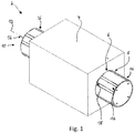
- Fig. 1 shows a filter device 2, which has a housing 4 with a receiving cavity 8 in which a filter holder 10 is received.
- the portafilter 10 is movably arranged in relation to the cavity 8 in the direction of a portafilter longitudinal axis 12.
- the housing 4 has, in a manner known per se, an inlet for introducing a fluid to be filtered and an outlet for discharging the filtered fluid (not shown).
- the portafilter 10 has a plurality of integrally formed portafilter elevations 16 on its outside.
- the receiving cavity 8 of the housing 4 is cylindrical.
- gaps or cavities 18 are formed between the receiving cavity 8 and the filter holder 10 in the area of housing wall sections 6, by means of which a low fluid flow is possible during operation.
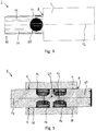
- Fig. 2 shows the filter device 2 in a side view.
- Fig. 3 shows the structural design of the portafilter 10 on the basis of a sectional illustration, cut along the plane AA Fig. 2 .
- the filter holder 10 has filter elements 14 by means of which the fluid is filtered.
- the portafilter 10 has a total of four portafilter elevations 16 which are arranged uniformly spaced around the circumference of the portafilter 10.
- the arrangement of the portafilter elevations 16 has the effect, in addition to centering the portafilter 10 in the receiving cavity 8, that several gaps or cavities 18 are formed between the wall section 6 and the portafilter 10, and within these gaps or cavities 18 during operation Fluid flow is enabled.
- Fig. 4 the filter device 2 is shown in a so-called screen change position.
- the filter holder 10 has been moved out of the housing 4 so far that one of the filter elements 14 is accessible from outside the housing 4 and can be exchanged or serviced.
- Fig. 5 the filtering device 2 is in an operating position in which fluid can be filtered by means of the filter elements 14. In the filtering position, the filter elements 14 are not accessible from outside the filtering device 2.
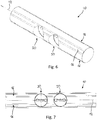
- the Figures 6 7 and 7 show a portafilter 10 without filter elements 14 inserted into the filter element receptacles 20.
- the portafilter elevations 16 are in the present case evenly spaced around the circumference of the portafilter 10 and extend in the direction of the longitudinal axis 12 of the portafilter 10 and in a straight line.
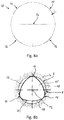
- the cross section of the portafilter 10 is shown in Figure 8a shown.
- the arrangement of the portafilter elevations 16, which are evenly spaced along the circumference, is illustrated again.
- the portafilter 10 has four portafilter elevations, the invention not being limited to this arrangement. Rather, it is also possible to arrange three portafilter elevations 16 on the portafilter 10 or a larger number of portafilter elevations 16.
- the elevations 16 extend in the direction of the longitudinal axis 12 of the portafilter 10 and in particular in a straight line.
- the elevations 16 have a height h in the range of approximately 0.05-3 mm, preferably in the range of approximately 0.1-0.2 mm, compared to the other diameter of the filter holder 10.
- the elevations 16 are formed from metal, but can also be formed from another, preferably low-wear material, such as in particular plastic.
- Figure 8b shows an alternative embodiment of a portafilter 10 '.
- the portafilter 10 ′ which is arranged in a cylindrical receiving cavity 8, has a cross-section 22 of the same thickness.
- the cross-section 22 of the same thickness is embodied in the present case as a triangular cross-section 22 of the same thickness.
- portafilter 10 ' shows larger gaps or cavities 18 between the housing wall section 6 and the portafilter 10'.
- the configuration of the portafilter 10 'with the cross-section 22 of the same thickness enables a higher fluid flow between the receiving cavity 8 and the portafilter 10', the portafilter 10 'being exactly centered in the receiving cavity 8 at the same time.
- FIGS 9 to 13 show an embodiment of a shut-off valve 102 with a housing 104, which has wall sections 106 and forms a receiving cavity 108.
- the shut-off valve 102 is based on the same inventive idea as the filtering device 2.
- the housing 104 has a first inlet / outlet 120 and a second inlet / outlet 122.
- a valve pin 110 is arranged in the receiving cavity 108 and is arranged axially movable relative to the housing 104 along a valve pin longitudinal axis 112.
- the valve pin 110 has a continuous flow channel in the form of a preferably cylindrical bore 124, which when it is in fluid-conducting connection with the first inlet / outlet 120 and the second inlet / outlet due to a relevant positioning of the valve pin 110 relative to the housing 104.
- Outlet 122 is located, releases a channel from the first inlet / outlet 120 to the second inlet / outlet 122 and blocks a fluid flow from the first inlet / outlet 120 to the second inlet / outlet 122 when the flow channel is in non-fluid-conducting Connection to the first inlet / outlet 120 and the second inlet / outlet 122 is located.
- the shut-off valve 102 is thus in a passage position in which a fluid flow from the first inlet / outlet 120 to the second inlet / outlet 122 is released. If the valve pin 110 is in the Figures 12 and 13, so the valve pin 110 blocks a fluid flow from the first inlet / outlet 120 to the second inlet / outlet 122. The shut-off valve 102 is located in the in the Figures 12 and 13 shown in a locked position.
- the valve pin 110 has a plurality of integrally formed valve pin elevations 116 on its outside.
- gaps or cavities 118 are formed in the areas between the valve pin elevations 116 and the wall sections 106, with a slight fluid flow in these gaps or cavities 118 Operation is possible.
- An arrangement of the valve pin elevations 116 along the circumference of the valve pin 110 also has the effect that the latter is essentially centered within the cavity 108 of the housing 104.
- valve pin 110 can alternatively be designed to be rotationally symmetrical and the housing wall sections 106 can have elevations and / or recesses.
- both the valve pin 110 can have integrally formed elevations 116 and / or a non-rotationally symmetrical cross section, and the housing wall sections 106 for their part can have elevations and / or recesses.
- the valve pin 110 can be configured analogously to the illustration in FIG Figure 8a have a plurality of elevations 116 spaced apart uniformly along its circumference or else, as in FIG Figure 8b shown, a cross-section of the same thickness or a polygonal or elliptical cross-section.
Landscapes
- Engineering & Computer Science (AREA)
- Mechanical Engineering (AREA)
- General Engineering & Computer Science (AREA)
- Chemical & Material Sciences (AREA)
- Chemical Kinetics & Catalysis (AREA)
- Extrusion Moulding Of Plastics Or The Like (AREA)
- Valve Housings (AREA)
- Sliding Valves (AREA)
Abstract
Die Erfindung betrifft eine Vorrichtung zum Filtrieren eines Fluids, insbesondere einer Verunreinigungen aufweisenden Kunststoff-Schmelze, mit einem Gehäuse, welches mindestens einen Einlass zum Einleiten des Fluids und einen Auslass zum Abgeben des Fluids sowie einen in dem Gehäuse durch Wandabschnitte des Gehäuses ausgebildeten Hohlraum zum Aufnehmen eines Siebträgers aufweist und einen beweglich in dem Hohlraum des Gehäuses angeordneten und eine Längsachse aufweisenden Siebträger zum Aufnehmen mindestens eines Filterelements zum Filtrieren des Fluids.Erfindungsgemäß wird vorgeschlagen, dass der Siebträger außen mehrere integral ausgebildete Erhebungen aufweist und/oder an den Hohlraum begrenzenden Wandabschnitten des Gehäuses Erhebungen und/oder Ausnehmungen ausgebildet sind, derart, dass zwischen dem Wandabschnitt und dem Siebträger mehrere Spalte/Hohlräume ausgebildet sind, mittels derer ein geringer Fluidfluss im Betrieb ermöglicht ist. Die Erfindung betrifft ferner eine Ventilanordnung.The invention relates to a device for filtering a fluid, in particular a plastic melt containing impurities, with a housing which has at least one inlet for introducing the fluid and an outlet for dispensing the fluid and a cavity formed in the housing through wall sections of the housing for receiving a portafilter and a portafilter which is movably arranged in the cavity of the housing and has a longitudinal axis for receiving at least one filter element for filtering the fluid. According to the invention, it is proposed that the portafilter has several integrally formed elevations on the outside and / or wall sections of the housing delimiting the cavity Elevations and / or recesses are formed in such a way that a plurality of gaps / cavities are formed between the wall section and the portafilter, by means of which a low fluid flow is made possible during operation. The invention also relates to a valve arrangement.
Description
Die Erfindung betrifft eine Vorrichtung zum Filtrieren eines Fluids, insbesondere einer Verunreinigungen aufweisenden Kunststoff-Schmelze, mit einem Gehäuse, welches mindestens einen Einlass zum Einleiten des Fluids und einen Auslass zum Abgeben des Fluids sowie einen in dem Gehäuse durch Wandabschnitte des Gehäuses ausgebildeten Hohlraum zum Aufnehmen eines Siebträgers aufweist, und einen beweglich in dem Hohlraum des Gehäuses angeordneten und eine Längsachse aufweisenden Siebträger zum Aufnehmen mindestens eines Filterelements zum Filtrieren des Fluids.The invention relates to a device for filtering a fluid, in particular a plastic melt containing impurities, with a housing which has at least one inlet for introducing the fluid and one outlet for discharging the fluid and a cavity formed in the housing through wall sections of the housing for receiving a portafilter, and a portafilter which is movably arranged in the cavity of the housing and has a longitudinal axis for receiving at least one filter element for filtering the fluid.
Derartige Vorrichtungen zum Filtrieren eines Fluids sind aus dem Stand der Technik bekannt. Gattungsgemäße Filtriervorrichtungen weisen wenigstens einen Siebträger auf, in dem ein oder mehrere Filterelemente angeordnet sind. Der Siebträger ist abschnittsweise in einem Gehäuse-Hohlraum aufgenommen und relativ zu diesem beweglich angeordnet. Dabei kann der Siebträger in eine Filtrierstellung gebracht werden, in welcher über den Gehäuseeinlass zugeführtes Fluid durch den Filter des Siebträgers in Richtung des Fluidauslasses geführt und filtriert wird, und in eine sogenannte Siebwechselstellung, bei welcher der Siebträger so aus dem Gehäuse-Hohlraum bewegt wird, dass das eine oder die mehreren Filterelemente zugänglich werden und ausgetauscht oder gewartet werden können. Nach dem Austausch- oder Wartungsvorgang wird der Siebträger erneut in die Filtrierstellung gebracht und der Filtriervorgang sodann fortgesetzt.Such devices for filtering a fluid are known from the prior art. Filter devices of the generic type have at least one portafilter in which one or more filter elements are arranged. The portafilter is received in sections in a housing cavity and is arranged to be movable relative to this. The portafilter can be brought into a filtering position in which fluid supplied via the housing inlet is guided through the filter of the portafilter in the direction of the fluid outlet and filtered, and in a so-called screen change position, in which the portafilter is moved out of the housing cavity, that one or the other several filter elements are accessible and can be exchanged or serviced. After the replacement or maintenance process, the portafilter is returned to the filtering position and the filtering process is then continued.
Bei aus dem Stand der Technik vorbekannten Filtriervorrichtungen ist der Siebträger zumeist nahezu spielfrei in dem Hohlraum des Gehäuses angeordnet. Diese spielfreie Anordnung des Siebträgers in dem Gehäuse-Hohlraum dichtet den Siebträger gegenüber dem Gehäuse ab, womit ein Austritt von Schmelze auch bei hohen Betriebsdrücken vermieden wird.In the case of filter devices known from the prior art, the portafilter is usually arranged in the cavity of the housing with almost no play. This backlash-free arrangement of the portafilter in the housing cavity seals the portafilter from the housing, so that an escape of melt is avoided even at high operating pressures.
Es hat sich jedoch bei der Verarbeitung einiger Schmelze-Materialien gezeigt, dass ein hohes Maß an Dichtigkeit zwischen Siebträger und Gehäuse-Hohlraum Nachteile mit sich bringt. So lässt sich bei der Verarbeitung von Polycarbonat-Schmelzen eine sogenanntes "Vercracken" beobachten. Im Kontaktbereich zwischen Siebträger und Gehäuse-Hohlraum bilden sich hierbei Kohleschichten aus, welche dazu führen können, dass sich der Siebträger in der Aufnahme verkeilt und nur unter großem Aufwand und mit großer Kraft entfernbar ist. Bei der Verarbeitung von zellulosebasierten Lyocell-Schmelzen hat sich darüber hinaus gezeigt, dass eine Stagnation der Schmelze im Bereich zwischen Siebträger und Gehäuse-Hohlraum in Verbindung mit dem Siebträger- bzw. Gehäusematerial - typischerweise Stahl - ein explosives Gemisch bilden kann, was ebenfalls unerwünscht ist.However, when processing some melt materials it has been shown that a high degree of tightness between the portafilter and the housing cavity has disadvantages. So-called "cracking" can be observed when processing polycarbonate melts. In the contact area between the portafilter and the housing cavity, carbon layers are formed, which can lead to the portafilter becoming wedged in the receptacle and can only be removed with great effort and force. When processing cellulose-based Lyocell melts, it has also been shown that stagnation of the melt in the area between the portafilter and the housing cavity in connection with the portafilter or housing material - typically steel - can form an explosive mixture, which is also undesirable .
Zur Überwindung einiger der beschriebenen Nachteile schlägt die
Auch wirkt sich bei einigen Anwendungsbereichen nachteilig aus, dass das Siebträgergrundmaterial, zumeist Stahl, einen unterschiedlichen Wärmeausdehnungskoeffizienten im Vergleich zu den vorgeschlagenen Kunststoffen aufweist. Darüber hinaus erhöht die Verwendung derartiger Abstandshalter die Fertigungskomplexität derartiger Siebträger, da an dem Siebträger Befestigungsmöglichkeiten für die Abstandshalter vorgehalten werden müssen. Je nach verwendetem Kunststoff unterliegen die Abstandshalter ferner einem erhöhten Verschließ und sind damit regelmäßig auszutauschen.In some areas of application, it is also disadvantageous that the basic material of the filter holder, mostly steel, has a different coefficient of thermal expansion compared to the proposed plastics. In addition, the use of such spacers increases the manufacturing complexity of such portafilter, since fastening options for the spacers must be provided on the portafilter. Depending on the plastic used, the spacers are also subject to increased wear and tear and must therefore be replaced regularly.
Vor diesem Hintergrund lag der Erfindung die Aufgabe zugrunde, eine Filtriervorrichtung der eingangs bezeichneten Art dahingehend weiterzubilden, dass die im Stand der Technik aufgefundenen Nachteile möglichst weitgehend behoben werden. Insbesondere soll eine Filtriervorrichtung angegeben werden, die einen Austausch des Fluides zwischen dem Siebträger und dem Gehäuse-Hohlraum ermöglicht, eine exaktere Führung des Siebträgers relativ zu dem Gehäuse-Hohlraum sicherstellt sowie verschleißbeständiger ist.Against this background, the invention was based on the object of developing a filtering device of the type indicated at the outset in such a way that the disadvantages found in the prior art are eliminated as far as possible. In particular, a filtering device is to be specified which enables the fluid to be exchanged between the portafilter and the housing cavity, ensures more precise guidance of the portafilter relative to the housing cavity and is more wear-resistant.
Erfindungsgemäß wird die Aufgabe bei der Filtriervorrichtung dadurch gelöst, dass der Siebträger außen mehrere integral ausgebildete Erhebungen und/oder einen nicht rotationssymmetrischen Querschnitt aufweist und/oder an den Hohlraum begrenzenden Wandabschnitten des Gehäuses Erhebungen und/oder Ausnehmungen ausgebildet sind, derart, dass zwischen dem Wandabschnitt und dem Siebträger mehrere Spalte/Hohlräume ausgebildet sind, mittels derer ein geringer Fluidfluss im Betrieb ermöglicht ist.According to the invention, the problem with the filtering device is achieved in that the portafilter has a plurality of integrally formed elevations and / or a non-rotationally symmetrical cross-section and / or elevations and / or recesses are formed on the wall sections of the housing delimiting the cavity, such that between the wall section and a plurality of gaps / cavities are formed in the portafilter, by means of which a low fluid flow is made possible during operation.
Der Erfindung liegt damit die Erkenntnis zugrunde, Erhebungen und/oder Ausnehmungen an dem Siebträger und/oder an den hohlraumbegrenzenden Wandabschnitten des Gehäuses auszubilden, wobei die Erhebungen und/oder Ausnehmungen einstückig mit dem jeweiligen Körper - Siebträger und/oder Gehäuse - und mithin integral und aus demselben Werkstoff ausgebildet sind. Die Erhebungen und/oder Ausnehmungen führen dazu, dass zwischen dem Wandabschnitt und dem Siebträger mehrere Spalte/Hohlräume ausgebildet sind, sodass Fluid im Betrieb in diesen Spalten/Hohlräumen fließen kann, ein Fluidaustritt aus der Vorrichtung gleichsam jedoch minimal ist. Die Ausbildung von Kohleschichten bei der Verarbeitung von Polycarbonat-Schmelzen oder die Entstehung explosiver Gemische bei der Verarbeitung von Lyocell-Schmelzen kann hierdurch verhindert werden.The invention is thus based on the knowledge of forming elevations and / or recesses on the portafilter and / or on the cavity-delimiting wall sections of the housing, the elevations and / or recesses being integral with the respective body - portafilter and / or housing - and therefore integral and are made of the same material. The elevations and / or recesses result in a plurality of gaps / cavities being formed between the wall section and the portafilter, so that fluid can flow in these gaps / cavities during operation, but fluid leakage from the device is minimal, as it were. This can prevent the formation of carbon layers when processing polycarbonate melts or the formation of explosive mixtures when processing Lyocell melts.
Dabei geht mit der integralen Ausbildung der Erhebungen und/oder Ausnehmungen eine reduzierte Fertigungskomplexität im Vergleich zu mehrstückigen und mehrere Materialien aufweisenden Lösungen einher. Sowohl Siebträger als auch Gehäuse können aus jeweils einem einzigen Werkstück gefertigt und mittels Standard-Bearbeitungsmethoden kostengünstig bearbeitet werden. Ferner hat die einstückige bzw. integrale Ausbildung der Erhebungen und/oder Ausnehmungen den Vorteil, dass sämtliche Abschnitte des Gehäuses und des Siebträgers einer konstanten Wärmeausdehnung unterliegen, sodass die auftretenden Spaltmaße auch bei Erwärmung oder Abkühlung der Vorrichtung weitestgehend konstant bleiben. Auch unterliegen die Erhebungen im Vergleich zu einer Ausbildung derselben aus Kunststoff einem geringeren Verschleiß. Insoweit wird auch das Auftreten verschleißabhängig variabler Spaltmaße vermieden.The integral design of the elevations and / or recesses is accompanied by a reduced manufacturing complexity compared to multi-piece and multi-material solutions. Both portafilter and housing can each be made from a single workpiece and machined cost-effectively using standard machining methods. Furthermore, the one-piece or integral design of the elevations and / or recesses has the advantage that all sections of the housing and the portafilter are subject to constant thermal expansion, so that the gap dimensions that occur remain largely constant even when the device is heated or cooled. The elevations are also subject to less wear than when they are made of plastic. In this respect, the occurrence of wear-dependent, variable gap dimensions is also avoided.
Gemäß eines zweiten Aspektes der Erfindung bzw. gemäß einer vorteilhaften Weiterbildung der Erfindung gemäß des ersten Aspektes wird erfindungsgemäß vorgeschlagen, dass der Siebträger außen mindestens drei, vorzugsweise vier Erhebungen aufweist und/oder an den Hohlraum begrenzenden Wandabschnitten des Gehäuses Erhebungen und/oder Ausnehmungen ausgebildet sind, die so entlang des Umfangs des Siebträgers verteilt angeordnet sind, dass der Siebträger im Wesentlichen zentriert innerhalb des Hohlraumes des Gehäuses angeordnet ist, derart, dass zwischen dem Wandabschnitt und dem Siebträger mehrere Spalte/Hohlräume ausgebildet sind, mittels derer ein geringer Fluidfluss im Betrieb ermöglicht ist.According to a second aspect of the invention or according to an advantageous development of the invention according to the first aspect, the invention proposes that the portafilter has at least three, preferably four elevations on the outside and / or elevations and / or recesses are formed on the wall sections of the housing delimiting the cavity , which are arranged distributed along the circumference of the portafilter so that the portafilter is arranged essentially centered within the cavity of the housing, in such a way that a plurality of gaps / cavities are formed between the wall section and the portafilter, by means of which a low fluid flow is possible during operation is.
Durch die Anordnung der wenigstens drei Erhebungen entlang des Siebträger-Umfangs wird sichergestellt, dass der Siebbolzen zentriert innerhalb des Hohlraumes des Gehäuses aufgenommen und gleichzeitig ein geringer Fluidfluss zwischen dem Gehäuse und dem Siebträger im Betrieb ermöglicht ist.The arrangement of the at least three elevations along the portafilter periphery ensures that the screen bolt is received in a centered manner within the cavity of the housing and that, at the same time, a low fluid flow is enabled between the housing and the portafilter during operation.
Gemäß einer bevorzugten Weiterbildung erstrecken sich die Erhebungen im Wesentlichen in Richtung einer Längsachse des Siebträgers und geradlinig, vorzugsweise über im Wesentlichen die gesamte Länge des Siebträgers. Derartige Erhebungsgeometrien sind nicht nur exakt und mittels Standardfertigungsverfahren fertigbar, sondern ermöglichen gleichzeitig eine sichere, zentrierte und verkantungsfreie Führung des Siebträgers in dem Gehäuse-Hohlraum.According to a preferred development, the elevations extend essentially in the direction of a longitudinal axis of the portafilter and in a straight line, preferably over essentially the entire length of the portafilter. Elevation geometries of this type can not only be manufactured precisely and by means of standard manufacturing processes, but at the same time enable safe, centered and tilt-free guidance of the portafilter in the housing cavity.
Weiterhin ist bevorzugt, dass die Erhebungen gleichmäßig beanstandet in Richtung des Umfangs des Siebträgers angeordnet sind. Eine gleichmäßige Beabstandung der Erhebungen in Richtung des Umfangs des Siebträgers bewirkt eine exakte Zentrierung des Siebträgers innerhalb des Gehäuse-Hohlraumes, wobei gleichzeitig ein großer Umfangsbereich des Siebträgers dem gewünschten geringen Fluidfluss zwischen dem Gehäuse und dem Siebträger im Betrieb zugänglich ist.It is also preferred that the elevations are arranged spaced apart uniformly in the direction of the circumference of the portafilter. Uniform spacing of the elevations in the direction of the circumference of the portafilter causes the portafilter to be centered exactly within the housing cavity, while at the same time a large circumferential area of the portafilter is accessible to the desired low fluid flow between the housing and the portafilter during operation.
Gemäß einer bevorzugten Weiterbildung weisen die Erhebungen gegenüber dem sonstigen Durchmesser des Siebträgers eine Höhe im Bereich von etwa 0,05 - 3 mm, vorzugsweise im Bereich von etwa 0,1 - 0,2 mm, auf. Der angegebene Höhenbereich hat sich als besonders geeignet zur Erzielung einer hinreichenden Dichtwirkung zwischen Gehäuse und Siebträger einerseits und zur Ermöglichung des gewünschten geringen Fluidfluss zwischen den Bauteilen andererseits herausgestellt.According to a preferred development, the elevations have a height in the range of approximately 0.05-3 mm, preferably in the range of approximately 0.1-0.2 mm, compared to the other diameter of the portafilter. The specified height range has proven to be particularly suitable for achieving a sufficient sealing effect between the housing and the portafilter on the one hand and to enable the desired low fluid flow between the components on the other hand.
Ferner sind die Erhebungen gemäß einer bevorzugten Ausführungsform aus einem verschleißarmen Material, insbesondere Metall oder Kunststoff ausgebildet. Die Verwendung von Metall weist den Vorteil einer gleichen bzw. weitestgehend ähnlichen Wärmeausdehnung der Erhebungen relativ zu dem Gehäuse und dem Siebträger auf, sodass die auftretenden Spaltmaße weitestgehend konstant bleiben. Die Verwendung von Kunststoffen hat sich darüber hinaus für einige Anwendungsbereiche bzw. Schmelze-Materialien aufgrund einer hohen chemischen Beständigkeit einiger Kunststoffe sowie deren Gleiteigenschaften als vorzugswürdig erwiesen.Furthermore, according to a preferred embodiment, the elevations are formed from a low-wear material, in particular metal or plastic. The use of metal has the advantage of the same or largely similar thermal expansion of the elevations relative to the housing and the portafilter, so that the gap dimensions that occur remain largely constant. The use of plastics has also proven to be preferable for some areas of application or melt materials due to the high chemical resistance of some plastics and their sliding properties.
Die Erfindung wird dadurch weitergebildet, dass der Siebträger senkrecht zur Siebträger-Längsachse und/oder der den Hohlraum begrenzende Wandabschnitt des Gehäuses einen gleichdickförmigen Querschnitt aufweist, welcher die Erhebungen des Siebträgers und/oder die Erhebungen und/oder Ausnehmungen der Wandabschnitte ausbildet.The invention is further developed in that the portafilter perpendicular to the portafilter longitudinal axis and / or the wall section of the housing delimiting the cavity has a cross-section of the same thickness, which forms the elevations of the portafilter and / or the elevations and / or recesses of the wall sections.
Als gleichdickförmiger Querschnitt wird ein solcher bezeichnet, bei dem zwei gegenüberliegende parallele Stützgeraden, die den Querschnitt berühren, immer den gleichen Abstand zueinander haben. Die Stützgeraden sind so zu wählen, dass sie jeweils mindestens einen Punkt gemeinsam mit der Grenze des Querschnitts haben aber keinen gemeinsamen Punkt mit einem Inneren des Querschnitts. Das Vorsehen eines gleichdickförmigen Querschnitts hat sich dabei als besonders vorteilhaft erwiesen, um sowohl eine exakte Zentrierung des Siebbolzens relativ zu dem Gehäuse-Hohlraum zu erzielen als auch einen entsprechend dimensionierten Spalt oder Hohlraum bereitzustellen, um einen geringen Fluidfluss zwischen dem Wandabschnitt und dem Siebträger zu ermöglichen.A cross-section of the same thickness is referred to as a cross-section in which two opposite parallel supporting straight lines that touch the cross-section are always at the same distance from one another. The support lines are to be chosen so that they each have at least one point in common with the boundary of the cross-section but no common point with an interior of the cross-section. The provision of a cross-section of the same thickness has proven to be particularly advantageous in order to achieve both exact centering of the sieve pin relative to the housing cavity and to provide a correspondingly dimensioned gap or cavity to enable a low fluid flow between the wall section and the sieve carrier .
Vorzugsweise ist der den Hohlraum begrenzende Wandabschnitt des Gehäuses zylindrisch ausgebildet, wobei der Siebträger senkrecht zur Siebträger-Längsachse einen gleichdickförmigen Querschnitt aufweist. Ein entsprechender Siebträger realisiert die oben genannten Vorteile und ist kompatibel zu bestehenden Gehäusesystemen.The wall section of the housing delimiting the cavity is preferably of cylindrical design, the portafilter having a cross-section of the same thickness perpendicular to the longitudinal axis of the portafilter. A corresponding portafilter realizes the advantages mentioned above and is compatible with existing housing systems.
Gemäß einer alternativen Ausführungsform ist der Siebträger zylindrisch ausgebildet, wobei der den Hohlraum begrenzende Wandabschnitt des Gehäuses einen gleichdickförmigen Querschnitt aufweist.According to an alternative embodiment, the filter holder is cylindrical, the wall section of the housing delimiting the cavity having a cross-section of the same thickness.
Weiterhin ist bevorzugt, dass der gleichdickförmige Querschnitt als dreikantiger oder vierkantiger Gleichdickquerschnitt ausgebildet ist. Je nach zu verarbeitendem Schmelze-Material und dem gewünschten Fluidflussgrad zwischen dem Wandabschnitt und dem Siebträger kann der gleichdickförmige Querschnitt geeignet als dreikantiger oder vierkantiger Gleichdickquerschnitt ausgewählt werden.It is also preferred that the cross-section of the same thickness is designed as a triangular or square cross-section of constant thickness. Depending on the melt material to be processed and the desired degree of fluid flow between the wall section and the portafilter, the cross-section of the same thickness can be suitably selected as a triangular or square cross-section of constant thickness.
Die Erfindung wird dadurch weitergebildet, dass der gleichdickförmige Querschnitt als Reuleaux-Dreieck ausgebildet ist. Ein solches Dreieck basiert auf einem gleichseitigen Dreieck, bei dem anstelle der Schenkel des Dreiecks Kreissegmente vorgesehen sind. Der Radius dieser Kreissegmente entspricht der Seitenlänge des zugrundeliegenden gleichseitigen Dreiecks. Die Ausbildung des gleichdickförmigen Querschnitts als Reuleaux-Dreieck bringt zum einen den Vorteil einer einfachen Fertigbarkeit mit sich und ermöglicht zum anderen eine exakte Zentrierung des Siebträgers relativ zu dem Wandabschnitt des Gehäuses. Die Querschnittsfläche ist im Vergleich zu anderen Gleichdickausprägungen minimal, woraus ein vergrößertes Volumen der Spalte bzw. Hohlräume resultiert.The invention is further developed in that the cross-section of the same thickness is designed as a Reuleaux triangle. Such a triangle is based on an equilateral triangle in which circular segments are provided instead of the legs of the triangle. The radius of these circle segments corresponds to the side length of the underlying equilateral triangle. The formation of the cross-section of the same thickness as a Reuleaux triangle has the advantage of being easy to manufacture and enables the portafilter to be centered exactly relative to the wall section of the housing. The cross-sectional area is minimal compared to other constructions of equal thickness, which results in an increased volume of the gaps or cavities.
Gemäß einer alternativen Ausführungsform weist der Siebträger senkrecht zur Siebträger-Längsachse und/oder der den Hohlraum begrenzende Wandabschnitt des Gehäuses einen polygonalen Querschnitt auf, insbesondere aufweisend 3, 4, 5 oder mehr Ecken, wobei die Ecken vorzugsweise abgerundet ausgebildet sind. Gemäß einer alternativ bevorzugten Ausführungsform weist der Siebträger senkrecht zur Siebträger-Längsachse und/oder der den Hohlraum begrenzende Wandabschnitt einen ellipsenförmigen Querschnitt auf.According to an alternative embodiment, the portafilter has a polygonal cross section perpendicular to the portafilter longitudinal axis and / or the wall section of the housing delimiting the cavity, in particular having 3, 4, 5 or more corners, the corners preferably being rounded. According to an alternatively preferred embodiment, the portafilter has an elliptical cross-section perpendicular to the portafilter longitudinal axis and / or the wall section delimiting the cavity.
Die Ausgestaltung des Siebträger-Querschnitts oder Wandabschnitt-Querschnitts als Polygon bzw. Ellipse hat sich als alternative vorteilhafte Ausgestaltung erwiesen, um eine hinreichende und gut beeinflussbare Fluidströmung zwischen dem Wandabschnitt und dem Siebträger sicherzustellen, Siebträger und Gehäuse relativ zueinander zu zentrieren, und weiterhin eine kostengünstige Fertigbarkeit zu realisieren.The configuration of the portafilter cross-section or wall section cross-section as a polygon or ellipse has proven to be an alternative advantageous configuration to ensure a sufficient and easily controllable fluid flow between the wall section and the portafilter, to center the portafilter and housing relative to one another, and also an inexpensive one Realize manufacturability.
Die Erfindung wird dadurch weitergebildet, dass der Siebträger in dem Hohlraum radial und/oder axial beweglich angeordnet ist. Hierbei hat sich gezeigt, dass neben der rein axialen Bewegbarkeit des Siebträgers eine radiale Bewegungskomponente desselben dazu beitragen kann, die Bildung von Kohleschichten bei der Verarbeitung von Polycarbonat-Schmelzen sowie die Bildung explosiver Gemische bei der Verwendung von Lyocell-Schmelzen durch eine radiale oder kombinierte radial-axiale Bewegung des Siebträgers zu reduzieren.The invention is further developed in that the portafilter is arranged so that it can move radially and / or axially in the cavity. It has been shown that, in addition to the purely axial mobility of the portafilter, a radial movement component of the same can contribute to the formation of carbon layers when processing polycarbonate melts and the formation of explosive mixtures when using Lyocell melts through a radial or combined radial -to reduce axial movement of the portafilter.
Die Erfindung ist vorstehend unter Bezugnahme auf eine Filtriervorrichtung beschrieben worden. In einem weiteren Aspekt betrifft die Erfindung eine Ventilanordnung, insbesondere für eine Verunreinigungen aufweisende Kunststoffschmelze, mit einem Gehäuse, welches mindestens einen Einlass zum Einleiten des Fluids und mindestens eine Auslass zum Abgeben des Fluids sowie einen in dem Gehäuse durch Wandabschnitte des Gehäuses ausgebildeten Hohlraum zum Aufnehmen eines Ventilbolzens aufweist und einen beweglich in dem Hohlraum des Gehäuses angeordneten Ventilbolzen zum selektiven Freigeben, Verteilen und/oder Sperren des Fluidflusses durch das Gehäuse.The invention has been described above with reference to a filtering device. In a further aspect, the invention relates to a valve arrangement, in particular for a plastic melt containing impurities, with a housing which has at least one inlet for introducing the fluid and at least one outlet for discharging the fluid and a cavity formed in the housing through wall sections of the housing for receiving a valve pin and a valve pin movably arranged in the cavity of the housing for selectively releasing, distributing and / or blocking the flow of fluid through the housing.
Auch bei aus dem Stand der Technik vorbekannten Ventilanordnungen ergeben sich die in Bezug auf die Filtriervorrichtung beschriebenen Nachteile, insbesondere bei der Verarbeitung von Polycarbonat-Schmelzen betreffend die Ablagerung von Kohleschichten zwischen Ventilgehäuse und Ventilbolzen sowie die Gefahr der Bildung von explosiven Gemischen bei der Verarbeitung von Lyocell-Schmelzen.Even with valve arrangements known from the prior art, the disadvantages described in relation to the filter device arise, in particular when processing polycarbonate melts with regard to the deposition of carbon layers between the valve housing and valve pin and the risk of explosive mixtures forming when processing Lyocell -Melt.
Insoweit löst die Erfindung die eingangs bezeichnete Aufgabe in Bezug auf die Ventilanordnung, indem der Ventilbolzen außen mehrere integral ausgebildete Erhebungen aufweist und/oder einen nicht rotationssymmetrischen Querschnitt und/oder an den Hohlraum begrenzenden Wandabschnitten des Gehäuses Erhebungen und/oder Ausnehmungen ausgebildet sind, derart, dass zwischen dem Wandabschnitt und dem Ventilbolzen mehrere Spalte/Hohlräume ausgebildet sind, mittels derer ein geringer Fluidfluss im Betrieb ermöglicht ist.In this respect, the invention solves the problem described at the beginning with regard to the valve arrangement in that the valve pin has several integrally formed elevations on the outside and / or a non-rotationally symmetrical cross section and / or elevations and / or recesses are formed on the cavity delimiting wall sections of the housing, such as that a plurality of gaps / cavities are formed between the wall section and the valve pin, by means of which a low fluid flow is made possible during operation.
Die Ventilanordnung macht sich die gleichen Vorteile zunutze wie die erfindungsgemäße Filtriervorrichtung. Insbesondere verhindert oder vermindert die Ventilanordnung bei Verwendung mit Polycarbonat-Schmelzen durch Ermöglichung eines geringen Fluidflusses zwischen dem Wandabschnitt und dem Ventilbolzen die Ablagerung von Kohleschichten zwischen Ventilbolzen und Ventilgehäuse, wodurch eine Schwergängigkeit oder eine Blockierung des Ventilbolzens vermieden wird und im Falle von Lyocell-Anwendungen die Bildung explosiver Gemische.The valve arrangement makes use of the same advantages as the filter device according to the invention. In particular, when used with polycarbonate melts, the valve arrangement prevents or reduces the deposition of carbon layers between the valve pin and the valve housing by allowing a low fluid flow between the wall section and the valve pin, which prevents the valve pin from moving or jamming and, in the case of Lyocell applications, the Formation of explosive mixtures.
Die integrale Ausbildung der Erhebungen und/oder Ausnehmungen vereinfacht weiterhin die Fertigung, führt zu vorhersagbaren und auch bei Wärmeausdehnung weitestgehend konstanten Spaltmaßen und ermöglicht eine hohe Zentrierung der Komponenten relativ zueinander.The integral design of the elevations and / or recesses further simplifies production, leads to predictable and largely constant gap dimensions, even with thermal expansion, and enables the components to be highly centered relative to one another.
Gemäß eines weiteren Aspektes der Erfindung bzw. gemäß einer vorteilhaften Weiterbildung der erfindungsgemäßen Ventilanordnung wird vorgeschlagen, dass der Ventilbolzen außen mindestens drei, vorzugsweise vier Erhebungen aufweist und/oder an den Hohlraum begrenzenden Wandabschnitten des Gehäuses Erhebungen und/oder Ausnehmungen ausgebildet sind, die so entlang des Umfangs des Ventilbolzens verteilt angeordnet sind, dass der Ventilbolzen im Wesentlichen zentriert innerhalb des Hohlraumes des Gehäuses angeordnet ist, derart, dass zwischen dem Wandabschnitt und dem Ventilbolzen mehrere Spalte/Hohlräume ausgebildet sind, mittels derer ein geringer Fluidfluss im Betrieb ermöglicht ist.According to a further aspect of the invention or according to an advantageous further development of the valve arrangement according to the invention, it is proposed that the valve pin have at least three, preferably four elevations on the outside and / or elevations and / or recesses are formed on the cavity-delimiting wall sections of the housing, which are thus formed along the circumference of the valve pin are arranged distributed, that the valve pin is arranged essentially centered within the cavity of the housing, such that a plurality of gaps / cavities are formed between the wall section and the valve pin, by means of which a low fluid flow is possible during operation.
Die Erfindung wird dadurch weitergebildet, dass sich die Erhebungen im Wesentlichen in Richtung der Längsachse des Ventilbolzens und geradlinig erstrecken, bevorzugt im Wesentlichen über die gesamte Länge des Ventilbolzens. Gemäß einer bevorzugten Ausführungsform sind die Erhebungen gleichmäßig beanstandet in Richtung des Umfangs des Ventilbolzens angeordnet. Ferner ist bevorzugt, dass die Erhebungen gegenüber dem sonstigen Durchmesser des Ventilbolzens eine Höhe im Bereich von etwa 0,05 - 3 mm, vorzugsweise im Bereich von etwa 0,1 - 0,2 mm, aufweisen.The invention is further developed in that the elevations extend essentially in the direction of the longitudinal axis of the valve pin and in a straight line, preferably essentially over the entire length of the valve pin. According to a preferred embodiment, the elevations are evenly spaced apart in the direction of the circumference of the valve pin. It is also preferred that the elevations have a height in the range of approximately 0.05-3 mm, preferably in the range of approximately 0.1-0.2 mm, compared to the other diameter of the valve pin.
Gemäß einer bevorzugten Ausführungsform sind die Erhebungen aus einem verschleißarmen Material, insbesondere Metall oder Kunststoff, ausgebildet. Die Erfindung wird dadurch weitergebildet, dass der Ventilbolzen senkrecht zur Ventilbolzen-Längsachse und/oder der Hohlraum begrenzende Wandabschnitt des Gehäuses einen gleichdickförmigen Querschnitt aufweist, welcher die Erhebungen des Ventilbolzens und/oder die Erhebungen und/oder Ausnehmungen der Wandabschnitte ausbildet. Vorzugsweise ist der gleichdickförmige Querschnitt als dreikantiger oder vierkantiger gleichdicke Querschnitt ausgebildet.According to a preferred embodiment, the elevations are made from a low-wear material, in particular metal or plastic. The invention is further developed in that the valve pin perpendicular to the longitudinal axis of the valve pin and / or the wall section of the housing delimiting the cavity has a cross-section of the same thickness, which forms the elevations of the valve pin and / or the elevations and / or recesses of the wall sections. The cross-section of the same thickness is preferably designed as a triangular or square cross-section of the same thickness.
Hinsichtlich der Vorteile einer demgemäßen Ausbildung des Ventilbolzens und/oder des den Hohlraum begrenzende Wandabschnittes des Gehäuses sei auf obige Ausführungen betreffend die Filtriervorrichtung verwiesen, welche hier in analoger Weise Gültigkeit besitzen.With regard to the advantages of a corresponding design of the valve pin and / or of the wall section of the housing delimiting the cavity, reference is made to the above statements relating to the filtering device, which apply here in an analogous manner.
Gemäß einer bevorzugten Ausführungsform ist der gleichdickförmige Querschnitt als Reuleaux-Dreieck ausgebildet. Ein solcher Querschnitt ist mit wenig Aufwand fertigbar, ermöglicht zwischen dem Wandabschnitt und dem Ventilbolzen einen Fluidfluss im Betrieb und gleichzeitig eine Zentrierung des Ventilbolzens relativ zu dem Gehäuse.According to a preferred embodiment, the cross-section of the same thickness is designed as a Reuleaux triangle. Such a cross section can be produced with little effort, enables fluid flow between the wall section and the valve pin during operation and at the same time allows the valve pin to be centered relative to the housing.
Gemäß einer alternativen Ausführungsform weist der Ventilbolzen senkrecht zur Ventilbolzen-Längsachse und/oder der den Hohlraum begrenzende Wandabschnitt des Gehäuses einen polygonalen Querschnitt auf, insbesondere aufweisend 3, 4, 5 oder mehr Ecken. Vorzugsweise sind die Ecken abgerundet ausgebildet.According to an alternative embodiment, the valve pin perpendicular to the valve pin longitudinal axis and / or the wall section of the housing delimiting the cavity has a polygonal cross section, in particular having 3, 4, 5 or more corners. The corners are preferably rounded.
Gemäß einer weiteren alternativen Ausführungsform weist der Ventilbolzen senkrecht zur Ventilbolzen-Längsachse und/oder der den Hohlraum begrenzende Wandabschnitt einen ellipsenförmigen Querschnitt auf.According to a further alternative embodiment, the valve pin perpendicular to the valve pin longitudinal axis and / or the wall section delimiting the cavity has an elliptical cross section.
Hinsichtlich der Vorteile der ebengenannten Ausführungsformen sei auf obige Ausführungen betreffend die Filtriervorrichtung verwiesen.With regard to the advantages of the above-mentioned embodiments, reference is made to the above statements relating to the filtration device.
Die Erfindung wird dadurch weitergebildet, dass die Ventilanordnung als eines der folgenden ausgebildet ist: Absperrventil, Verteilerventil. Die beschriebenen Ventiltypen werden häufig bei Kunststoff-Schmelze verarbeitenden Vorrichtungen verwendet.The invention is further developed in that the valve arrangement is designed as one of the following: shut-off valve, distributor valve. The valve types described are often used in plastic melt processing devices.
Die Erfindung wird nachfolgend anhand bevorzugter Ausführungsbeispiele unter Bezugnahme auf die beigefügten Figuren näher beschrieben.The invention is described in more detail below on the basis of preferred exemplary embodiments with reference to the accompanying figures.
Hierbei zeigen:
- Fig. 1
- ein erstes Ausführungsbeispiel einer erfindungsgemäßen Filtriervorrichtung in einer perspektivischen Ansicht;
- Fig. 2
- das Ausführungsbeispiel der erfindungsgemäßen Filtriervorrichtung gemäß
Fig. 1 in einer Seitenansicht; - Fig. 3
- das Ausführungsbeispiel der erfindungsgemäßen Filtriervorrichtung gemäß
den Figuren 1 und2 in einer Schnittansicht; - Fig. 4, 5
- weitere Ansichten der erfindungsgemäßen Filtriervorrichtung gemäß den Figuren 1-3;
- Fig. 6, 7
- einen erfindungsgemäßen Siebträger in einer perspektivischen Ansicht sowie einer Seitenansicht;
- Fig. 8a
- eine Querschnittsansicht des erfindungsgemäßen Siebträgers;
- Fig. 8b
- ein alternatives Ausführungsbeispiel eines erfindungsgemäßen Siebträgers in einer Schnittansicht;
- Fig. 9-13
- ein Ausführungsbeispiel eines erfindungsgemäßen Absperrventils in verschiedenen Ansichten und Betriebszuständen; und
- Fig. 1
- a first embodiment of a filter device according to the invention in a perspective view;
- Fig. 2
- the embodiment of the filter device according to the invention according to
Fig. 1 in a side view; - Fig. 3
- the embodiment of the filter device according to the invention according to the
Figures 1 and2 in a sectional view; - Fig. 4, 5
- further views of the filter device according to the invention according to FIGS. 1-3;
- Fig. 6, 7
- a portafilter according to the invention in a perspective view and a side view;
- Figure 8a
- a cross-sectional view of the portafilter according to the invention;
- Figure 8b
- an alternative embodiment of a portafilter according to the invention in a sectional view;
- Fig. 9-13
- an embodiment of a shut-off valve according to the invention in different views and operating states; and
Der Siebträger 10 weist an seiner Außenseite mehrere integral ausgebildete Siebträger-Erhebungen 16 auf. Der Aufnahme-Hohlraum 8 des Gehäuses 4 ist zylindrisch ausgebildet. Dies hat zur Folge, dass sich zwischen dem Aufnahme-Hohlraum 8 und dem Siebträger 10 im Bereich von Gehäuse-Wandabschnitten 6 Spalte, bzw. Hohlräume 18 ausbilden, mittels derer ein geringer Fluidfluss im Betrieb möglich ist.
In
Die
Der Querschnitt des Siebträgers 10 ist in
Die
Der Ventilbolzen 110 weist einen durchgehenden Fließkanal in Form einer vorzugsweisen zylindrischen Bohrung 124 auf, welcher, wenn er sich aufgrund einer betreffenden Positionierung des Ventilbolzens 110 relativ zu dem Gehäuse 104 in fluidleitender Verbindung mit dem ersten Ein-/Auslass 120 sowie dem zweiten Ein-/Auslass 122 befindet, einen Kanal von dem ersten Ein-/Auslass 120 zum zweiten Ein-/Auslass 122 freigibt und einen Fluidfluss von dem ersten Ein-/Auslass 120 zu dem zweiten Ein-/Auslass 122 sperrt, wenn sich der Fließkanal in nicht fluidleitender Verbindung mit dem ersten Ein-/Auslass 120 sowie dem zweiten Ein-/Auslass 122 befindet.The
In dem in den
Der Ventilbolzen 110 weist an seiner Außenseite mehrere integral ausgebildete Ventilbolzen-Erhebungen 116 auf. Der Aufnahme-Hohlraum 108 des Gehäuses 104, bzw. die entsprechenden Gehäuse-Wandabschnitte 106, bilden einen zylindrischen Hohlraum aus. Dies hat, wie auch in analoger Weise bei der Filtriervorrichtung 2, zur Folge, dass sich in den Bereichen zwischen den Ventilbolzen-Erhebungen 116 und den Wandabschnitten 106 Spalte bzw. Hohlräume 118 ausbilden, wobei in diesen Spalten bzw. Hohlräumen 118 ein geringer Fluidfluss im Betrieb möglich ist. Eine Anordnung der Ventilbolzen-Erhebungen 116 entlang des Umfangs des Ventilbolzens 110 bewirkt ferner, dass dieser im Wesentlichen zentriert wird innerhalb des Hohlraums 108 des Gehäuses 104.The
Erfindungsgemäß kann dabei der Ventilbolzen 110 alternativ rotationssymmetrisch ausgebildet sein und die Gehäuse-Wandabschnitte 106 Erhebungen und/oder Ausnehmungen aufweisen. Darüber hinaus können erfindungsgemäß sowohl der Ventilbolzen 110 integral ausgebildete Erhebungen 116 und/oder einen nicht rotationssymmetrischen Querschnitt aufweisen als auch die Gehäuse-Wandabschnitte 106 ihrerseits Erhebungen und/oder Ausnehmungen. Der Ventilbolzen 110 kann analog zur Darstellung in
- 22
- FiltriervorrichtungFiltering device
- 44th
- Gehäusecasing
- 66th
- Gehäuse-WandabschnitteHousing wall sections
- 88th
- Aufnahme-HohlraumReceiving cavity
- 10, 10'10, 10 '
- SiebträgerPortafilter
- 1212th
- Siebträger-LängsachsePortafilter longitudinal axis
- 1414th
- FilterelementFilter element
- 1616
- Siebträger-ErhebungenPortafilter elevations
- 1818th
- Spalt/HohlraumGap / cavity
- 2020th
- FilterelementaufnahmeFilter element holder
- 2222nd
- Gleichdickförmiger Querschnitt (dreikantig)Uniform cross-section (triangular)
- hH
- Höhe der ErhebungenElevation
- 102102
- AbsperrventilShut-off valve
- 104104
- Gehäusecasing
- 106106
- Gehäuse-WandabschnitteHousing wall sections
- 108108
- Aufnahme-HohlraumReceiving cavity
- 110110
- VentilbolzenValve pin
- 112112
- Ventilbolzen-LängsachseValve pin longitudinal axis
- 116116
- Ventilbolzen-ErhebungenValve pin elevations
- 118118
- Spalt/HohlraumGap / cavity
- 120120
- Erster Ein-/AuslassFirst inlet / outlet
- 122122
- Zweiter Ein-/AuslassSecond inlet / outlet
- 124124
- FließkanalFlow channel
- 202202
- VerteilerventilDistribution valve
- 204204
- Gehäusecasing
- 206206
- Gehäuse-WandabschnitteHousing wall sections
- 208208
- Aufnahme-HohlraumReceiving cavity
- 210210
- VentilbolzenValve pin
- 212212
- Ventilbolzen-LängsachseValve pin longitudinal axis
- 216216
- Ventilbolzen-ErhebungenValve pin elevations
- 218218
- Spalt/HohlraumGap / cavity
- 220220
- Erster Ein-/AuslassFirst inlet / outlet
- 222222
- Zweiter Ein-/AuslassSecond inlet / outlet
- 224224
- Dritter Ein-/AuslassThird inlet / outlet
- 226226
- Vierter Ein-/AuslassFourth inlet / outlet
- 228228
- Oberer Ein-/AuslassUpper inlet / outlet
Claims (13)
einem Gehäuse (4), welches mindestens einen Einlass zum Einleiten des Fluids und einen Auslass zum Abgeben des Fluids sowie einen in dem Gehäuse (4) durch Wandabschnitte (6) des Gehäuses (4) ausgebildeten Hohlraum (8) zum Aufnehmen eines Siebträgers (10, 10') aufweist,
einen beweglich in dem Hohlraum (6) des Gehäuses (4) angeordneten und eine Längsachse (12) aufweisenden Siebträger (10, 10') zum Aufnehmen mindestens eines Filterelements (14) zum Filtrieren des Fluids,
dadurch gekennzeichnet, dass der Siebträger (10, 10') außen mehrere integral ausgebildete Erhebungen (16) und/oder einen nicht rotationssymmetrischen Querschnitt (22) aufweist
und/oder an den Hohlraum (6) begrenzenden Wandabschnitten (6) des Gehäuses (4) Erhebungen und/oder Ausnehmungen ausgebildet sind,
derart, dass zwischen dem Wandabschnitt (6) und dem Siebträger (10, 10') mehrere Spalte/Hohlräume (18) ausgebildet sind, mittels derer ein geringer Fluidfluss im Betrieb ermöglicht ist.Filtration device (2) for filtering a fluid, in particular a plastic melt containing contamination
a housing (4) which has at least one inlet for introducing the fluid and an outlet for discharging the fluid as well as a cavity (8) formed in the housing (4) by wall sections (6) of the housing (4) for receiving a filter holder (10) , 10 '),
a portafilter (10, 10 ') which is movably arranged in the cavity (6) of the housing (4) and has a longitudinal axis (12) for receiving at least one filter element (14) for filtering the fluid,
characterized in that the portafilter (10, 10 ') has a plurality of integrally formed elevations (16) on the outside and / or a non-rotationally symmetrical cross-section (22)
and / or raised areas and / or recesses are formed on the wall sections (6) of the housing (4) delimiting the cavity (6),
such that a plurality of gaps / cavities (18) are formed between the wall section (6) and the portafilter (10, 10 '), by means of which a low fluid flow is made possible during operation.
dadurch gekennzeichnet, dass der Siebträger (10, 10') außen mindestens drei, vorzugsweise vier Erhebungen (16) aufweist und/oder an den Hohlraum (8) begrenzenden Wandabschnitten (6) des Gehäuses (4) Erhebungen und/oder Ausnehmungen ausgebildet sind, die so entlang des Umfangs des Siebträgers (10, 10') verteilt angeordnet sind, dass der Siebträger (10, 10') im Wesentlichen zentriert innerhalb des Hohlraumes (8) des Gehäuses (4) angeordnet ist,
derart, dass zwischen dem Wandabschnitt (6) und dem Siebträger (10, 10') mehrere Spalte/Hohlräume (18) ausgebildet sind, mittels derer ein geringer Fluidfluss im Betrieb ermöglicht ist.Filtration device (2) according to the preamble of claim 1 or according to claim 1,
characterized in that the portafilter (10, 10 ') has at least three, preferably four elevations (16) on the outside and / or elevations and / or recesses are formed on the wall sections (6) of the housing (4) delimiting the cavity (8), which are arranged distributed along the circumference of the portafilter (10, 10 ') that the portafilter (10, 10') is arranged essentially centered within the cavity (8) of the housing (4),
such that a plurality of gaps / cavities (18) are formed between the wall section (6) and the portafilter (10, 10 '), by means of which a low fluid flow is made possible during operation.
dadurch gekennzeichnet, dass die Erhebungen (16) sich im Wesentlichen in Richtung der Längsachse (12) des Siebträgers (10, 10') und geradlinig erstrecken.Filtration device (2) according to at least one of the preceding claims,
characterized in that the elevations (16) extend essentially in the direction of the longitudinal axis (12) of the portafilter (10, 10 ') and in a straight line.
dadurch gekennzeichnet, dass die Erhebungen (16) gleichmäßig beanstandet in Richtung des Umfangs des Siebträgers (10, 10') angeordnet sind.Filtration device (2) according to at least one of the preceding claims,
characterized in that the elevations (16) are evenly spaced apart in the direction of the circumference of the portafilter (10, 10 ').
dadurch gekennzeichnet, dass die Erhebungen (16) gegenüber dem sonstigen Durchmesser des Siebträgers (10) eine Höhe (h) im Bereich von etwa 0,05 - 3 mm, vorzugsweise im Bereich von etwa 0,1 - 0,2 mm, aufweisen.Filtration device (2) according to at least one of the preceding claims,
characterized in that the elevations (16) have a height (h) in the range of approximately 0.05-3 mm, preferably in the range of approximately 0.1-0.2 mm, compared to the other diameter of the portafilter (10).
dadurch gekennzeichnet, dass die Erhebungen (16) aus einem verschleißarmen Material, insbesondere Metall oder Kunststoff ausgebildet sind.Filtration device (2) according to at least one of the preceding claims,
characterized in that the elevations (16) are made from a low-wear material, in particular metal or plastic.
dadurch gekennzeichnet, dass der Siebträger (10') senkrecht zur Siebträger-Längsachse (12) und/oder der den Hohlraum (8) begrenzende Wandabschnitt (6) des Gehäuses (4) einen gleichdickförmigen Querschnitt (22) aufweist, welcher die Erhebungen (16) des Siebträgers (10') und/oder die Erhebungen und/oder Ausnehmungen der Wandabschnitte (6) ausbildet.Filtration device (2) according to at least one of the preceding claims,
characterized in that the portafilter (10 ') perpendicular to the portafilter longitudinal axis (12) and / or the wall section (6) of the housing (4) delimiting the cavity (8) has a cross-section (22) of the same thickness, which the elevations (16 ) of the portafilter (10 ') and / or the elevations and / or recesses of the wall sections (6).
dadurch gekennzeichnet, dass der gleichdickförmige Querschnitt (22) als dreikantiger oder vierkantiger Gleichdickquerschnitt (22) ausgebildet ist.Filtration device (2) according to claim 7,
characterized in that the cross-section (22) of equal thickness is designed as a triangular or square cross-section of equal thickness (22).
dadurch gekennzeichnet, dass der gleichdickförmige Querschnitt (22) als Reuleaux-Dreieck ausgebildet ist.Filtering device (2) according to at least one of claims 7 or 8,
characterized in that the cross-section (22) of uniform thickness is designed as a Reuleaux triangle.
dadurch gekennzeichnet, dass der Siebträger (10, 10') senkrecht zur Siebträger-Längsachse (12) und/oder der den Hohlraum (8) begrenzende Wandabschnitt (6) des Gehäuses (4) einen polygonalen Querschnitt aufweist, insbesondere aufweisend drei, vier, fünf oder mehr Ecken, wobei die Ecken vorzugsweise abgerundet ausgebildet sind.Filtration device (2) according to at least one of the preceding claims,
characterized in that the portafilter (10, 10 ') perpendicular to the portafilter longitudinal axis (12) and / or the wall section (6) of the housing (4) delimiting the cavity (8) has a polygonal cross section, in particular having three, four, five or more corners, the corners preferably being rounded.
dadurch gekennzeichnet, dass der Siebträger (10, 10') senkrecht zur Siebträger-Längsachse (12) und/oder der den Hohlraum (8) begrenzende Wandabschnitt (6) einen ellipsenförmigen Querschnitt aufweist.Filtration device (2) according to at least one of the preceding claims,
characterized in that the portafilter (10, 10 ') perpendicular to the portafilter longitudinal axis (12) and / or the wall section (6) delimiting the cavity (8) has a Has elliptical cross-section.
dadurch gekennzeichnet, dass der Siebträger (10, 10') in dem Hohlraum (8) radial und/oder axial beweglich angeordnet ist.Filtration device (2) according to at least one of the preceding claims,
characterized in that the portafilter (10, 10 ') is arranged in the cavity (8) such that it can move radially and / or axially.
einem Gehäuse (104, 204), welches mindestens einen Einlass zum Einleiten des Fluids und mindestens einem Auslass zum Abgeben des Fluids sowie einen in dem Gehäuse (104, 204) durch Wandabschnitte (106, 206) des Gehäuses (104, 204) ausgebildeten Hohlraum (108, 208) zum Aufnehmen eines Ventilbolzens (110, 210) aufweist,
einen beweglich in dem Hohlraum (108, 208) des Gehäuses (104, 204) angeordneten Ventilbolzen (110, 210) zum selektiven Freigeben, Verteilen und/oder Sperren des Fluidflusses durch das Gehäuse (104, 204),
dadurch gekennzeichnet, dass der Ventilbolzen (110, 210) außen mehrere integral ausgebildete Erhebungen (116, 216) und/oder einen nicht rotationssymmetrischen Querschnitt aufweist und/oder an den Hohlraum (108, 208) begrenzenden Wandabschnitten (106, 206) des Gehäuses (104, 204) Erhebungen und/oder Ausnehmungen ausgebildet sind, derart, dass zwischen dem Wandabschnitt (106, 206) und dem Ventilbolzen (110, 210) mehrere Spalte/Hohlräume (118, 218) ausgebildet sind, mittels derer ein geringer Fluidfluss im Betrieb ermöglicht ist.Valve arrangement (102, 202), in particular for a plastic melt containing contamination
a housing (104, 204) which has at least one inlet for introducing the fluid and at least one outlet for discharging the fluid and a cavity formed in the housing (104, 204) by wall sections (106, 206) of the housing (104, 204) (108, 208) for receiving a valve pin (110, 210),
a valve pin (110, 210) movably arranged in the cavity (108, 208) of the housing (104, 204) for selectively releasing, distributing and / or blocking the flow of fluid through the housing (104, 204),
characterized in that the valve pin (110, 210) has a plurality of integrally formed elevations (116, 216) and / or a non-rotationally symmetrical cross-section and / or wall sections (106, 206) of the housing (106, 206) delimiting the cavity (108, 208) on the outside. 104, 204) elevations and / or recesses are formed such that a plurality of gaps / cavities (118, 218) are formed between the wall section (106, 206) and the valve pin (110, 210), by means of which a low fluid flow during operation is made possible.
Priority Applications (6)
| Application Number | Priority Date | Filing Date | Title |
|---|---|---|---|
| EP19212184.6A EP3827963A1 (en) | 2019-11-28 | 2019-11-28 | Device for filtering a fluid, especially a plastic melt with impurities, and valve arrangement for such a fluid |
| US17/780,639 US20230356118A1 (en) | 2019-11-28 | 2020-11-23 | Apparatus for filtering a fluid, in particular a plastic melt having impurities, and a valve arrangement for such a fluid |
| EP20820734.0A EP4065334A1 (en) | 2019-11-28 | 2020-11-23 | Apparatus for filtering a fluid, in particular a plastic melt having impurities, and a valve arrangement for such a fluid |
| PCT/US2020/061723 WO2021108284A1 (en) | 2019-11-28 | 2020-11-23 | Apparatus for filtering a fluid, in particular a plastic melt having impurities, and a valve arrangement for such a fluid |
| JP2022532035A JP2023505760A (en) | 2019-11-28 | 2020-11-23 | Apparatus for filtering fluids, especially plastic melts with impurities, and valve apparatus for such fluids |
| CN202080083003.XA CN114746244B (en) | 2019-11-28 | 2020-11-23 | Device for filtering a fluid, in particular a plastic melt with impurities, and valve device for such a fluid |
Applications Claiming Priority (1)
| Application Number | Priority Date | Filing Date | Title |
|---|---|---|---|
| EP19212184.6A EP3827963A1 (en) | 2019-11-28 | 2019-11-28 | Device for filtering a fluid, especially a plastic melt with impurities, and valve arrangement for such a fluid |
Publications (1)
| Publication Number | Publication Date |
|---|---|
| EP3827963A1 true EP3827963A1 (en) | 2021-06-02 |
Family
ID=68731878
Family Applications (2)
| Application Number | Title | Priority Date | Filing Date |
|---|---|---|---|
| EP19212184.6A Pending EP3827963A1 (en) | 2019-11-28 | 2019-11-28 | Device for filtering a fluid, especially a plastic melt with impurities, and valve arrangement for such a fluid |
| EP20820734.0A Withdrawn EP4065334A1 (en) | 2019-11-28 | 2020-11-23 | Apparatus for filtering a fluid, in particular a plastic melt having impurities, and a valve arrangement for such a fluid |
Family Applications After (1)
| Application Number | Title | Priority Date | Filing Date |
|---|---|---|---|
| EP20820734.0A Withdrawn EP4065334A1 (en) | 2019-11-28 | 2020-11-23 | Apparatus for filtering a fluid, in particular a plastic melt having impurities, and a valve arrangement for such a fluid |
Country Status (5)
| Country | Link |
|---|---|
| US (1) | US20230356118A1 (en) |
| EP (2) | EP3827963A1 (en) |
| JP (1) | JP2023505760A (en) |
| CN (1) | CN114746244B (en) |
| WO (1) | WO2021108284A1 (en) |
Families Citing this family (1)
| Publication number | Priority date | Publication date | Assignee | Title |
|---|---|---|---|---|
| EP3308940A1 (en) * | 2016-10-17 | 2018-04-18 | Next Generation Analytics GmbH | Filtering system for viscose or highly viscose liquids, in particular molten plastic and method for filtering viscose or highly-viscose liquids |
Citations (5)
| Publication number | Priority date | Publication date | Assignee | Title |
|---|---|---|---|---|
| DE29611292U1 (en) * | 1995-12-07 | 1996-10-31 | Kreyenborg Verwaltungen | Filter device for extrusion and injection molding machines |
| WO1998041305A2 (en) * | 1997-03-17 | 1998-09-24 | Lenzing Aktiengesellschaft | Use of iron mica in the production of moulds |
| DE202011106715U1 (en) * | 2011-10-12 | 2012-01-19 | Maag Pump Systems Gmbh | Device for distributing a plastic melt |
| EP3308939A1 (en) * | 2016-10-17 | 2018-04-18 | Nordson Corporation | Flow diverter valve for an extrusion system |
| DE102017115295B3 (en) * | 2017-07-07 | 2018-10-25 | Nordson Corporation | Filtration device and method for operating the same |
Family Cites Families (26)
| Publication number | Priority date | Publication date | Assignee | Title |
|---|---|---|---|---|
| GB563831A (en) * | 1943-05-11 | 1944-08-31 | John Graves Mckean | Improvements in and relating to strainers for liquids |
| GB915341A (en) * | 1958-07-29 | 1963-01-09 | Griffith May | Improvements in and relating to mechanical filters |
| NL6500067A (en) * | 1965-01-06 | 1966-07-07 | ||
| GB1464155A (en) * | 1975-02-14 | 1977-02-09 | Power House Eng Ltd | Valves for flowable materials |
| DD135595A1 (en) * | 1978-03-31 | 1979-05-16 | Heinz Goetzelt | FILTER CHANGE DEVICE, ESPECIALLY FOR PLASTIC PROCESSING EXTRACTERS |
| DE2942849C2 (en) * | 1979-10-24 | 1983-03-17 | Joachim Kreyenborg & Co, 4400 Münster | Filter device for extrusion presses |
| CA1133216A (en) * | 1979-12-12 | 1982-10-12 | John J. Rosenfeld | Process for production of embossed resin products |
| US5368276A (en) * | 1984-01-12 | 1994-11-29 | Pfeiffer; Robert W. | Valve with truncated aperture providing enhanced rangeability and logarithmic flow characteristic |
| SU1388308A1 (en) * | 1986-09-15 | 1988-04-15 | Украинский Научно-Исследовательский И Конструкторский Институт По Разработке Машин И Оборудования Для Переработки Пластических Масс,Резины И Искусственной Кожи | Extruder for processing and filtering plastics |
| EP0707878B1 (en) * | 1994-10-19 | 2000-01-19 | BemaTec SA | Filter apparatus with back flow cleaning |
| DE19618090A1 (en) * | 1996-05-06 | 1997-11-13 | Hoechst Diafoil Gmbh | Filter device for evenly filtering plastic melts |
| DE10214013A1 (en) * | 2002-03-28 | 2003-10-23 | Maag Pump Systems Textron Gmbh | Filter unit for filtering fluids, in particular plastic melts comprises a filter screen sandwiched between filter and support plates pressed against each other |
| DE102004049643A1 (en) * | 2004-10-11 | 2006-04-20 | Plastmachines International Gmbh | Filter device for a processing plant of thermoplastic material and filter method |
| US7832426B2 (en) * | 2006-09-05 | 2010-11-16 | Fisher Controls International Llc | Parabolic bonnet for three-way valve |
| US20090057592A1 (en) * | 2007-08-28 | 2009-03-05 | Lakhan Haresh C | Flow control and closure valve with axial flow in the valve element |
| DE102010000925B4 (en) * | 2010-01-14 | 2012-04-19 | Kreyenborg Beteiligungen Und Verwaltungen Gmbh & Co. Kg | Siebträgerelement for a filtration device with at least one Siebkavität |
| DE102010029591B4 (en) * | 2010-06-01 | 2012-11-22 | Kreyenborg Verwaltungen Und Beteiligungen Gmbh & Co. Kg | Filter device for high-viscosity media |
| WO2012153115A1 (en) * | 2011-05-06 | 2012-11-15 | Azza As | Filter arrangement |
| EP2548711B1 (en) * | 2011-07-21 | 2017-07-05 | Coperion GmbH | Filter unit for an extruder assembly ; a filter assembly and corresponding filter changing device for an extruder assembly with such a filter unit |
| US8876517B2 (en) * | 2012-09-28 | 2014-11-04 | Nordson Corporation | Filtration apparatus with a sealing device |
| DE102015010532A1 (en) * | 2015-08-12 | 2017-02-16 | Hydac Filtertechnik Gmbh | Filter device and filter element |
| WO2017151481A1 (en) * | 2016-03-01 | 2017-09-08 | Cummins Filtration Ip, Inc. | Torsional no filter no run system and method |
| DE202016105013U1 (en) * | 2016-09-09 | 2016-09-23 | Nordson Corporation | Filter candle for separating impurities from a plastic melt |
| EP3308940A1 (en) * | 2016-10-17 | 2018-04-18 | Next Generation Analytics GmbH | Filtering system for viscose or highly viscose liquids, in particular molten plastic and method for filtering viscose or highly-viscose liquids |
| DE102017208179A1 (en) * | 2017-03-07 | 2018-09-13 | Robert Bosch Gmbh | Valve for controlling a fluid flow |
| US11260330B2 (en) * | 2018-02-09 | 2022-03-01 | Paul NEISER | Filtration apparatus and method |
-
2019
- 2019-11-28 EP EP19212184.6A patent/EP3827963A1/en active Pending
-
2020
- 2020-11-23 JP JP2022532035A patent/JP2023505760A/en active Pending
- 2020-11-23 WO PCT/US2020/061723 patent/WO2021108284A1/en unknown
- 2020-11-23 EP EP20820734.0A patent/EP4065334A1/en not_active Withdrawn
- 2020-11-23 US US17/780,639 patent/US20230356118A1/en active Pending
- 2020-11-23 CN CN202080083003.XA patent/CN114746244B/en active Active
Patent Citations (6)
| Publication number | Priority date | Publication date | Assignee | Title |
|---|---|---|---|---|
| DE29611292U1 (en) * | 1995-12-07 | 1996-10-31 | Kreyenborg Verwaltungen | Filter device for extrusion and injection molding machines |
| WO1998041305A2 (en) * | 1997-03-17 | 1998-09-24 | Lenzing Aktiengesellschaft | Use of iron mica in the production of moulds |
| EP0915729B1 (en) | 1997-03-17 | 2003-06-04 | Lenzing Aktiengesellschaft | Device for filtering an impure fluid |
| DE202011106715U1 (en) * | 2011-10-12 | 2012-01-19 | Maag Pump Systems Gmbh | Device for distributing a plastic melt |
| EP3308939A1 (en) * | 2016-10-17 | 2018-04-18 | Nordson Corporation | Flow diverter valve for an extrusion system |
| DE102017115295B3 (en) * | 2017-07-07 | 2018-10-25 | Nordson Corporation | Filtration device and method for operating the same |
Also Published As
| Publication number | Publication date |
|---|---|
| CN114746244A (en) | 2022-07-12 |
| EP4065334A1 (en) | 2022-10-05 |
| WO2021108284A1 (en) | 2021-06-03 |
| JP2023505760A (en) | 2023-02-13 |
| US20230356118A1 (en) | 2023-11-09 |
| CN114746244B (en) | 2024-03-15 |
Similar Documents
| Publication | Publication Date | Title |
|---|---|---|
| EP2651619B1 (en) | Apparatus for continuous filtering of mixed materials | |
| DE2933655C2 (en) | Device for processing plastics and polymer materials that can be plasticized by heat | |
| EP2411712B2 (en) | Diverter valve for highly viscous liquid | |
| DE3024108C2 (en) | ||
| EP2576180B1 (en) | Filtering apparatus for highly viscous media | |
| DE19813600A1 (en) | Static disc mixer | |
| EP0672443A1 (en) | Control device for at least two partial fluid streams | |
| EP0715692B1 (en) | Pump-protecting valve | |
| EP3827963A1 (en) | Device for filtering a fluid, especially a plastic melt with impurities, and valve arrangement for such a fluid | |
| DE3443752C2 (en) | ||
| DE4017558C2 (en) | Use of rotating bodies to vary the average cross section for the plastic material in planetary roller extruders | |
| EP1247635A2 (en) | Filter device for fluid plastic material | |
| DE102019131050A1 (en) | Flow lapping device for smoothing a surface of a workpiece | |
| EP2059378B1 (en) | Device for filtering a thermoplastic polymer melt | |
| WO2005087476A2 (en) | Device for filtering a fluid, particularly a liquefied plastic | |
| DE2808951A1 (en) | INJECTION NOZZLE FOR A PLASTIC INJECTION MOLDING MACHINE | |
| DE202013003829U1 (en) | Filter device for filtering fluid | |
| EP0195211B1 (en) | Installation for filtering metallic melts | |
| DE102019121953A1 (en) | Pressure reducing unit | |
| EP2907646B1 (en) | Large particle separation device | |
| DE102021115905B4 (en) | Multi-way valve unit for plastic melts and other medium to high-viscosity liquids | |
| DE19525524C2 (en) | Device for mixing and / or sieving and / or filtering thermoplastic melts | |
| EP1379866A2 (en) | Testing device for ultrasonic bar testing | |
| DE102022113909A1 (en) | Filtration element and filter device | |
| DE2340134C3 (en) | Screening device of an extruder |
Legal Events
| Date | Code | Title | Description |
|---|---|---|---|
| PUAI | Public reference made under article 153(3) epc to a published international application that has entered the european phase |
Free format text: ORIGINAL CODE: 0009012 |
|
| STAA | Information on the status of an ep patent application or granted ep patent |
Free format text: STATUS: THE APPLICATION HAS BEEN PUBLISHED |
|
| AK | Designated contracting states |
Kind code of ref document: A1 Designated state(s): AL AT BE BG CH CY CZ DE DK EE ES FI FR GB GR HR HU IE IS IT LI LT LU LV MC MK MT NL NO PL PT RO RS SE SI SK SM TR |
|
| STAA | Information on the status of an ep patent application or granted ep patent |
Free format text: STATUS: REQUEST FOR EXAMINATION WAS MADE |
|
| 17P | Request for examination filed |
Effective date: 20211202 |
|
| RBV | Designated contracting states (corrected) |
Designated state(s): AL AT BE BG CH CY CZ DE DK EE ES FI FR GB GR HR HU IE IS IT LI LT LU LV MC MK MT NL NO PL PT RO RS SE SI SK SM TR |
|
| P01 | Opt-out of the competence of the unified patent court (upc) registered |
Effective date: 20230528 |
|
| STAA | Information on the status of an ep patent application or granted ep patent |
Free format text: STATUS: EXAMINATION IS IN PROGRESS |
|
| 17Q | First examination report despatched |
Effective date: 20230912 |