EP3827706A1 - Adjustable beds - Google Patents
Adjustable beds Download PDFInfo
- Publication number
- EP3827706A1 EP3827706A1 EP20020559.9A EP20020559A EP3827706A1 EP 3827706 A1 EP3827706 A1 EP 3827706A1 EP 20020559 A EP20020559 A EP 20020559A EP 3827706 A1 EP3827706 A1 EP 3827706A1
- Authority
- EP
- European Patent Office
- Prior art keywords
- framework
- section
- bed
- selectively
- length
- Prior art date
- Legal status (The legal status is an assumption and is not a legal conclusion. Google has not performed a legal analysis and makes no representation as to the accuracy of the status listed.)
- Pending
Links
Images

Classifications
-
- A—HUMAN NECESSITIES
- A47—FURNITURE; DOMESTIC ARTICLES OR APPLIANCES; COFFEE MILLS; SPICE MILLS; SUCTION CLEANERS IN GENERAL
- A47C—CHAIRS; SOFAS; BEDS
- A47C20/00—Head-, foot- or like rests for beds, sofas or the like
- A47C20/04—Head-, foot- or like rests for beds, sofas or the like with adjustable inclination
- A47C20/041—Head-, foot- or like rests for beds, sofas or the like with adjustable inclination by electric motors
-
- A—HUMAN NECESSITIES
- A61—MEDICAL OR VETERINARY SCIENCE; HYGIENE
- A61G—TRANSPORT, PERSONAL CONVEYANCES, OR ACCOMMODATION SPECIALLY ADAPTED FOR PATIENTS OR DISABLED PERSONS; OPERATING TABLES OR CHAIRS; CHAIRS FOR DENTISTRY; FUNERAL DEVICES
- A61G7/00—Beds specially adapted for nursing; Devices for lifting patients or disabled persons
- A61G7/002—Beds specially adapted for nursing; Devices for lifting patients or disabled persons having adjustable mattress frame
- A61G7/015—Beds specially adapted for nursing; Devices for lifting patients or disabled persons having adjustable mattress frame divided into different adjustable sections, e.g. for Gatch position
-
- A—HUMAN NECESSITIES
- A61—MEDICAL OR VETERINARY SCIENCE; HYGIENE
- A61G—TRANSPORT, PERSONAL CONVEYANCES, OR ACCOMMODATION SPECIALLY ADAPTED FOR PATIENTS OR DISABLED PERSONS; OPERATING TABLES OR CHAIRS; CHAIRS FOR DENTISTRY; FUNERAL DEVICES
- A61G7/00—Beds specially adapted for nursing; Devices for lifting patients or disabled persons
- A61G7/05—Parts, details or accessories of beds
- A61G7/053—Aids for getting into, or out of, bed, e.g. steps, chairs, cane-like supports
-
- A—HUMAN NECESSITIES
- A61—MEDICAL OR VETERINARY SCIENCE; HYGIENE
- A61G—TRANSPORT, PERSONAL CONVEYANCES, OR ACCOMMODATION SPECIALLY ADAPTED FOR PATIENTS OR DISABLED PERSONS; OPERATING TABLES OR CHAIRS; CHAIRS FOR DENTISTRY; FUNERAL DEVICES
- A61G7/00—Beds specially adapted for nursing; Devices for lifting patients or disabled persons
- A61G7/10—Devices for lifting patients or disabled persons, e.g. special adaptations of hoists thereto
- A61G7/16—Devices for lifting patients or disabled persons, e.g. special adaptations of hoists thereto converting a lying surface into a chair
-
- A—HUMAN NECESSITIES
- A61—MEDICAL OR VETERINARY SCIENCE; HYGIENE
- A61G—TRANSPORT, PERSONAL CONVEYANCES, OR ACCOMMODATION SPECIALLY ADAPTED FOR PATIENTS OR DISABLED PERSONS; OPERATING TABLES OR CHAIRS; CHAIRS FOR DENTISTRY; FUNERAL DEVICES
- A61G7/00—Beds specially adapted for nursing; Devices for lifting patients or disabled persons
- A61G7/002—Beds specially adapted for nursing; Devices for lifting patients or disabled persons having adjustable mattress frame
- A61G7/018—Control or drive mechanisms
Definitions
- This invention relates to adjustable beds of the kind in which a plurality of individually articulated sections of the length of a mattress-carrying framework are selectively controllable to vary the relative angles between them, and to deploy the framework turned sideways in length with, selectively, a downward inclination to facilitate entry to, and exit from, the bed by a user.
- an adjustable bed of said above-specified kind wherein the bottom-end section of the framework is attached to a penultimate section of the framework to move with it in turning and elevation of the framework, and is selectively detachable from it to allow the framework to be selectively inclined downwardly to facilitate entry and exit of a user to, and from, the bed, when the framework is deployed turned sideways in length.
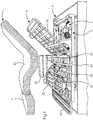
- the adjustable bed of this example has a mattress 1 that is carried by a five-section mattress-carrying framework 2 of a chassis frame 3 mounted on the floor-standing base 4 of the bed. More specifically, the mattress 1 is in two separate parts 10 and 11, in which the part 10 gives support for the back, seat, thighs and calves of the legs of the user-occupant of the bed. The mattress part 10 is itself supported for the user-occupant's back on a section 20 of the framework 2, and for his/her seat, thighs and calves on sections 21, 22 and 23 respectively, of the framework 2.
- the part 11 of the mattress 1 is a feet-supporting part for the user-occupant of the bed, and is carried by an end-section 24 of the frame 2.
- the sections 20-23 of the frame 2 are joined one to another by respective pairs of hinges 31 which enable them to be articulated with respect to one another for the adjustment of the comfort of the occupant-user of the bed.
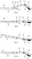
- the articulation to adjust the height and angularity of inclination of the sections 20-23 individually is carried out selectively by actuating equipment 5 (not shown in detail) located partly on the sections 20-23 themselves and partly on the chassis 3; an example of part of the equipment 5 located on the sections is illustrated in Figures 5 to 8 by an electrical motor 52 mounted on the section 22 and connected by a linkage 53 to the section 23 for varying the angle between the two sections.
- the equipment 5 includes provision for deploying the framework 2 turned about a central vertical axis (not shown) through the seat section 21, to extend lengthwise and downwardly at right-angles to the chassis 3 as illustrated in Figure 2 ; this deployment may include additionally slight tipping of the frame 2 forwardly so as to enhance further, assistance to the user in entering and exiting the bed.
- Figure 2 shows the bed turned in length to the right-hand side of the bed, and clearly provision may be made alternatively for it to be turned in the opposite direction, or selectively in either direction.
- Operations of the equipment 5 for adjustments to the relative angles of the sections 20-23 individually and to their deployment together in turning and downward inclination, as well as recovery from those deployed conditions, are actuated and controlled electrically by the bed-occupant using a hand-operated controller 51 (see Figure 2 ) and/or by wireless from a location remote from the bed.
- a pair of grab-rails 25, only one of which is shown in Figure 1 are provided for assisting and steadying the user when turning and other adjustments to the occupied bed are made, and during entry of a user into and exit from the bed.
- the bed of the invention (instead of having its bottom-end section of the framework detached permanently from the other sections of the mattress-supporting framework, and leaving the bottom-end and the foot-part of the mattress it carries, uninvolved in the articulations and turning of the framework), has provision for selectively attaching the bottom-end section of the framework to the other sections of the framework to be carried with them in their articulations and turning together.
- This has the advantage that the user-occupier of the bed rather than losing the benefit of the foot-section 11 of the mattress 1 during such turning and articulations retains it throughout.
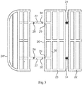
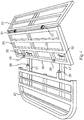
- the framework 2 with the bottom-end section 24 detached from it is turned by operation of the controller 51 to bring it into alignment in the horizontal plane with the section 23, as illustrated in Figure 4 , and to move its leading end 26 as illustrated in Figure 4 , onto a pair of guide-rails 27 that project rearwardly from the section 24.
- the angle of the section 22 is now increased via the controller 51 to urge the section 23, as represented in Figure 5 , into an inclined angle downwardly relative to the section 24 and for sliding of the leading end 26 closer to the section 24 along the guide-rails 27.
- Detachment of the section 24 from the section is achieved by returning the two sections 23 and 24 to alignment with one another as represented in Figure 6 and then operating the motor 52 to urge the section 23 into the angular condition represented in Figure 5 .
- This breaks the grip of the leaf-spring 32 on the cross-rail 33 and withdraws the sockets 29 from the spigots 28, thereby freeing the sections 23 and 24 from one another.
Landscapes
- Health & Medical Sciences (AREA)
- Nursing (AREA)
- General Health & Medical Sciences (AREA)
- Life Sciences & Earth Sciences (AREA)
- Animal Behavior & Ethology (AREA)
- Public Health (AREA)
- Veterinary Medicine (AREA)
- Invalid Beds And Related Equipment (AREA)
Abstract
Description
- This invention relates to adjustable beds of the kind in which a plurality of individually articulated sections of the length of a mattress-carrying framework are selectively controllable to vary the relative angles between them, and to deploy the framework turned sideways in length with, selectively, a downward inclination to facilitate entry to, and exit from, the bed by a user.
- With such beds, the height of the mattress-carrying framework when mounted on a floor-standing base of a conventional bed, would generally be insufficient to avoid obstruction of the downward-inclination of the framework by impact of its bottom-end and the foot-part of the mattress it carries, with the floor. This has resulted with the known forms of adjustable beds of the above-specified kind, in the bottom-end section of the frame being detached from the other sections, leaving it and the foot-part of the mattress it carries uninvolved in the articulations of the bed and its turning-deployments. This lack of involvement has significant disadvantage for comfort of the user of the bed.
- It is one of the object of the present invention to provide an adjustable bed by which the above disadvantage can be overcome.
- According to the present invention there is provided an adjustable bed of said above-specified kind wherein the bottom-end section of the framework is attached to a penultimate section of the framework to move with it in turning and elevation of the framework, and is selectively detachable from it to allow the framework to be selectively inclined downwardly to facilitate entry and exit of a user to, and from, the bed, when the framework is deployed turned sideways in length.
- An adjustable bed in accordance with the present invention will now be described by way of example, with reference to the accompanying drawings, in which:
-
Figure 1 is an exploded side-view of the adjustable bed of the invention showing it with its mattress lifted above a five-section mattress-carrying framework of a chassis of the bed, when mounted on a floor-standing base of the bed; -
Figure 2 is a general perspective view from the bottom-end of the bed when the mattress-carrying framework has been turned sideways in length to facilitate entry and exit of a user to, and from, the bed; -
Figures 3 and4 show respectively a plan view and a representation from above of successive stages in engagement for attachment of a bottom foot-section of the mattress-carrying framework with another, penultimate section of the five-section framework; -
Figures 5 and 6 are schematic side-views illustrating respectively the engagement action ofFigure 4 and the attachment resulting from it; and -
Figures 7 to 8 are schematic side-views illustrating respectively alternative articulations of the mattress-carrying framework of the adjustable bed of the invention. - Referring to
Figure 1 , the adjustable bed of this example has a mattress 1 that is carried by a five-section mattress-carryingframework 2 of achassis frame 3 mounted on the floor-standingbase 4 of the bed. More specifically, the mattress 1 is in twoseparate parts part 10 gives support for the back, seat, thighs and calves of the legs of the user-occupant of the bed. Themattress part 10 is itself supported for the user-occupant's back on asection 20 of theframework 2, and for his/her seat, thighs and calves onsections framework 2. - The
part 11 of the mattress 1 is a feet-supporting part for the user-occupant of the bed, and is carried by an end-section 24 of theframe 2. - The sections 20-23 of the
frame 2 are joined one to another by respective pairs ofhinges 31 which enable them to be articulated with respect to one another for the adjustment of the comfort of the occupant-user of the bed. The articulation to adjust the height and angularity of inclination of the sections 20-23 individually is carried out selectively by actuating equipment 5 (not shown in detail) located partly on the sections 20-23 themselves and partly on thechassis 3; an example of part of theequipment 5 located on the sections is illustrated inFigures 5 to 8 by anelectrical motor 52 mounted on thesection 22 and connected by alinkage 53 to thesection 23 for varying the angle between the two sections. - The
equipment 5 includes provision for deploying theframework 2 turned about a central vertical axis (not shown) through theseat section 21, to extend lengthwise and downwardly at right-angles to thechassis 3 as illustrated inFigure 2 ; this deployment may include additionally slight tipping of theframe 2 forwardly so as to enhance further, assistance to the user in entering and exiting the bed. (Figure 2 shows the bed turned in length to the right-hand side of the bed, and clearly provision may be made alternatively for it to be turned in the opposite direction, or selectively in either direction.) - Operations of the
equipment 5 for adjustments to the relative angles of the sections 20-23 individually and to their deployment together in turning and downward inclination, as well as recovery from those deployed conditions, are actuated and controlled electrically by the bed-occupant using a hand-operated controller 51 (seeFigure 2 ) and/or by wireless from a location remote from the bed. A pair of grab-rails 25, only one of which is shown inFigure 1 , are provided for assisting and steadying the user when turning and other adjustments to the occupied bed are made, and during entry of a user into and exit from the bed. - In contrast to the known beds of the kind specified as referred to above, the bed of the invention (instead of having its bottom-end section of the framework detached permanently from the other sections of the mattress-supporting framework, and leaving the bottom-end and the foot-part of the mattress it carries, uninvolved in the articulations and turning of the framework), has provision for selectively attaching the bottom-end section of the framework to the other sections of the framework to be carried with them in their articulations and turning together. This has the advantage that the user-occupier of the bed rather than losing the benefit of the foot-
section 11 of the mattress 1 during such turning and articulations retains it throughout. In the circumstances such as that ofFigure 2 , where the height of theframe 3 of thechassis 2 is limited to the extent of requiring the foot-section 24 with the its mattress-part 11, to be detached from theframework 2, such detachment with the bed of the present invention need not occur until downward inclination of the turned framework is required, rather than as with the known adjustable beds, when any turning takes place. - Attachment of the bottom-
end section 24 to thepenultimate section 23 of theframework 2 of the bed of the present invention, will now be described with reference toFigures 3 to 5 . - Referring to
Figure 3 , theframework 2 with the bottom-end section 24 detached from it, is turned by operation of thecontroller 51 to bring it into alignment in the horizontal plane with thesection 23, as illustrated inFigure 4 , and to move its leadingend 26 as illustrated inFigure 4 , onto a pair of guide-rails 27 that project rearwardly from thesection 24. The angle of thesection 22 is now increased via thecontroller 51 to urge thesection 23, as represented inFigure 5 , into an inclined angle downwardly relative to thesection 24 and for sliding of the leadingend 26 closer to thesection 24 along the guide-rails 27. With increase of the force applied to thesection 23 towards thesection 24 in this way, there is abutment between them accompanied by engagement of a pair of rear-facingspigots 28 of thesection 24 insockets 29 of thesection 23. Attachment of thesection 24 to thesection 23 is now completed by adjusting the angles of thesections sections Figure 6 . When thesection 23 moves into alignment with thesection 24, a pair of leaf-springs 32 at the ends of therails 27 snap into engagement against the rear face of across-rail 33 of thesection 23 trapping thesockets 29 engaged with thespigots 28 and thesections - With the
section 24 attached to thesection 23, the foot-supportingpart 11 of the mattress 1 is retained aligned with the bottom-end of the mattress-part 10. It is possible to provide hinges and a motor and linkage comparable with themotor 52 andlinkage 53 ofFigures 5 to 8 to engage between thesections sections - Detachment of the
section 24 from the section is achieved by returning the twosections Figure 6 and then operating themotor 52 to urge thesection 23 into the angular condition represented inFigure 5 . This breaks the grip of the leaf-spring 32 on thecross-rail 33 and withdraws thesockets 29 from thespigots 28, thereby freeing thesections
Claims (4)
- An adjustable bed in which a plurality of individually articulated sections of the length of a mattress-carrying framework are selectively controllable to vary the relative angles between them, and to deploy the framework turned sideways in length with, selectively, a downward inclination to facilitate entry to, and exit from, the bed by a user, characterised in that the bottom-end section of the framework is attached to a penultimate section of the framework to move with it in turning and elevation of the framework, and is selectively detachable from it to allow the framework to be selectively inclined downwardly to facilitate entry and exit of a user to, and from, the bed, when the framework is deployed turned sideways in length.
- The adjustable bed according to claim 1, wherein the bottom-end section of the framework when detached from the penultimate section of the framework, is controlled to be brought into alignment with the penultimate section of the framework onto guide rails projecting rearwardly from the penultimate section.
- The adjustable bed according to claim 1 or claim 2, wherein the bottom-end section and the penultimate section abut one another with spigot0socket engagement between them.
- The adjustable bed according to any one of claims 1 to 3, wherein the bottom-end section and the penultimate section are retained in abutment with one another under spring force.
Applications Claiming Priority (1)
| Application Number | Priority Date | Filing Date | Title |
|---|---|---|---|
| GBGB1917221.2A GB201917221D0 (en) | 2019-11-26 | 2019-11-26 | Adjustable beds |
Publications (1)
| Publication Number | Publication Date |
|---|---|
| EP3827706A1 true EP3827706A1 (en) | 2021-06-02 |
Family
ID=69137157
Family Applications (1)
| Application Number | Title | Priority Date | Filing Date |
|---|---|---|---|
| EP20020559.9A Pending EP3827706A1 (en) | 2019-11-26 | 2020-11-25 | Adjustable beds |
Country Status (2)
| Country | Link |
|---|---|
| EP (1) | EP3827706A1 (en) |
| GB (2) | GB201917221D0 (en) |
Citations (2)
| Publication number | Priority date | Publication date | Assignee | Title |
|---|---|---|---|---|
| GB1259181A (en) * | 1969-02-28 | 1972-01-05 | ||
| US20100005591A1 (en) * | 2008-07-09 | 2010-01-14 | Nikou Manouchehri | Hospital chair beds with drop foot section |
Family Cites Families (1)
| Publication number | Priority date | Publication date | Assignee | Title |
|---|---|---|---|---|
| US9265677B2 (en) * | 2009-12-23 | 2016-02-23 | Piedmont 361, Llc | Hospital chair beds with stowable stand-assist supports |
-
2019
- 2019-11-26 GB GBGB1917221.2A patent/GB201917221D0/en not_active Ceased
-
2020
- 2020-11-24 GB GB2018451.1A patent/GB2591572B/en active Active
- 2020-11-25 EP EP20020559.9A patent/EP3827706A1/en active Pending
Patent Citations (2)
| Publication number | Priority date | Publication date | Assignee | Title |
|---|---|---|---|---|
| GB1259181A (en) * | 1969-02-28 | 1972-01-05 | ||
| US20100005591A1 (en) * | 2008-07-09 | 2010-01-14 | Nikou Manouchehri | Hospital chair beds with drop foot section |
Also Published As
| Publication number | Publication date |
|---|---|
| GB202018451D0 (en) | 2021-01-06 |
| GB2591572B (en) | 2022-10-12 |
| GB201917221D0 (en) | 2020-01-08 |
| GB2591572A (en) | 2021-08-04 |
Similar Documents
| Publication | Publication Date | Title |
|---|---|---|
| EP2129262B1 (en) | Furniture device with adjustable angle between the seat and the back of the piece of furniture | |
| US6000758A (en) | Reclining lift chair | |
| KR101738062B1 (en) | Structure of leg-rest | |
| US9687400B2 (en) | Adjustable bed | |
| US9351574B2 (en) | Leisure chair | |
| US6095606A (en) | Adjusting device for chairs | |
| KR102359172B1 (en) | market device | |
| CN105026206A (en) | Seat arrangement for a vehicle | |
| KR20000076370A (en) | Apparatus and Method for Adjusting the Position of a Supporting Element in a Seat | |
| WO2006045316A1 (en) | Comfort wheelchair | |
| ES2913124T3 (en) | Robotic device for verticalization and assistance in the movement of subjects with severe motor disabilities | |
| JP6616834B2 (en) | Assistance robot | |
| KR20150079523A (en) | Gait rehabilitation robot to assist rehabilitation of patient | |
| EP2389914B1 (en) | Moving means of an inclinable or articulated backrest joined to a chair | |
| US7070233B2 (en) | Body support chair with adjustable handles | |
| KR20160129986A (en) | Stand up assistance equipment | |
| JP6209185B2 (en) | Transfer support device | |
| GB2591572A (en) | Adjustable beds | |
| KR101822631B1 (en) | Bedframe for patient | |
| KR101838105B1 (en) | Device to assist standing up | |
| JP2009119215A (en) | Standing / sitting assistance device | |
| CN217938563U (en) | Multi-position adjustable medical bed | |
| KR101931327B1 (en) | auxiliary apparatus for toilet | |
| KR20210037237A (en) | Standing-assisted chair | |
| KR101473876B1 (en) | Separable wheelchair for the old and the infirm and handicapped and public |
Legal Events
| Date | Code | Title | Description |
|---|---|---|---|
| PUAI | Public reference made under article 153(3) epc to a published international application that has entered the european phase |
Free format text: ORIGINAL CODE: 0009012 |
|
| STAA | Information on the status of an ep patent application or granted ep patent |
Free format text: STATUS: THE APPLICATION HAS BEEN PUBLISHED |
|
| AK | Designated contracting states |
Kind code of ref document: A1 Designated state(s): AL AT BE BG CH CY CZ DE DK EE ES FI FR GB GR HR HU IE IS IT LI LT LU LV MC MK MT NL NO PL PT RO RS SE SI SK SM TR |
|
| STAA | Information on the status of an ep patent application or granted ep patent |
Free format text: STATUS: REQUEST FOR EXAMINATION WAS MADE |
|
| 17P | Request for examination filed |
Effective date: 20211129 |
|
| RIN1 | Information on inventor provided before grant (corrected) |
Inventor name: KAVANAGH, MICHAEL FRANCIS |
|
| RBV | Designated contracting states (corrected) |
Designated state(s): AL AT BE BG CH CY CZ DE DK EE ES FI FR GR HR HU IE IS IT LI LT LU LV MC MK MT NL NO PL PT RO RS SE SI SK SM TR |
|
| RAP1 | Party data changed (applicant data changed or rights of an application transferred) |
Owner name: LAYBROOK GROUP LIMITED |
|
| STAA | Information on the status of an ep patent application or granted ep patent |
Free format text: STATUS: EXAMINATION IS IN PROGRESS |
|
| 17Q | First examination report despatched |
Effective date: 20230516 |