EP3827684A1 - Co-molded 3d elements - Google Patents
Co-molded 3d elements Download PDFInfo
- Publication number
- EP3827684A1 EP3827684A1 EP20214808.6A EP20214808A EP3827684A1 EP 3827684 A1 EP3827684 A1 EP 3827684A1 EP 20214808 A EP20214808 A EP 20214808A EP 3827684 A1 EP3827684 A1 EP 3827684A1
- Authority
- EP
- European Patent Office
- Prior art keywords
- support element
- partial member
- sole
- partial
- plastic material
- Prior art date
- Legal status (The legal status is an assumption and is not a legal conclusion. Google has not performed a legal analysis and makes no representation as to the accuracy of the status listed.)
- Pending
Links
Images


Classifications
-
- A—HUMAN NECESSITIES
- A43—FOOTWEAR
- A43B—CHARACTERISTIC FEATURES OF FOOTWEAR; PARTS OF FOOTWEAR
- A43B13/00—Soles; Sole-and-heel integral units
- A43B13/14—Soles; Sole-and-heel integral units characterised by the constructive form
- A43B13/141—Soles; Sole-and-heel integral units characterised by the constructive form with a part of the sole being flexible, e.g. permitting articulation or torsion
-
- A—HUMAN NECESSITIES
- A43—FOOTWEAR
- A43B—CHARACTERISTIC FEATURES OF FOOTWEAR; PARTS OF FOOTWEAR
- A43B1/00—Footwear characterised by the material
- A43B1/0072—Footwear characterised by the material made at least partially of transparent or translucent materials
-
- A—HUMAN NECESSITIES
- A43—FOOTWEAR
- A43B—CHARACTERISTIC FEATURES OF FOOTWEAR; PARTS OF FOOTWEAR
- A43B1/00—Footwear characterised by the material
- A43B1/14—Footwear characterised by the material made of plastics
-
- A—HUMAN NECESSITIES
- A43—FOOTWEAR
- A43B—CHARACTERISTIC FEATURES OF FOOTWEAR; PARTS OF FOOTWEAR
- A43B13/00—Soles; Sole-and-heel integral units
- A43B13/14—Soles; Sole-and-heel integral units characterised by the constructive form
- A43B13/16—Pieced soles
-
- A—HUMAN NECESSITIES
- A43—FOOTWEAR
- A43B—CHARACTERISTIC FEATURES OF FOOTWEAR; PARTS OF FOOTWEAR
- A43B13/00—Soles; Sole-and-heel integral units
- A43B13/14—Soles; Sole-and-heel integral units characterised by the constructive form
- A43B13/18—Resilient soles
- A43B13/181—Resiliency achieved by the structure of the sole
-
- A—HUMAN NECESSITIES
- A43—FOOTWEAR
- A43B—CHARACTERISTIC FEATURES OF FOOTWEAR; PARTS OF FOOTWEAR
- A43B21/00—Heels; Top-pieces or top-lifts
- A43B21/24—Heels; Top-pieces or top-lifts characterised by the constructive form
- A43B21/26—Resilient heels
-
- A—HUMAN NECESSITIES
- A43—FOOTWEAR
- A43B—CHARACTERISTIC FEATURES OF FOOTWEAR; PARTS OF FOOTWEAR
- A43B3/00—Footwear characterised by the shape or the use
- A43B3/0031—Footwear characterised by the shape or the use provided with a pocket, e.g. for keys or a card
-
- A—HUMAN NECESSITIES
- A43—FOOTWEAR
- A43B—CHARACTERISTIC FEATURES OF FOOTWEAR; PARTS OF FOOTWEAR
- A43B3/00—Footwear characterised by the shape or the use
- A43B3/0036—Footwear characterised by the shape or the use characterised by a special shape or design
- A43B3/0047—Footwear characterised by the shape or the use characterised by a special shape or design parts having a male and corresponding female profile to fit together, e.g. form-fit
-
- A—HUMAN NECESSITIES
- A43—FOOTWEAR
- A43B—CHARACTERISTIC FEATURES OF FOOTWEAR; PARTS OF FOOTWEAR
- A43B3/00—Footwear characterised by the shape or the use
- A43B3/0036—Footwear characterised by the shape or the use characterised by a special shape or design
- A43B3/0052—X-shaped or cross-shaped
-
- A—HUMAN NECESSITIES
- A43—FOOTWEAR
- A43B—CHARACTERISTIC FEATURES OF FOOTWEAR; PARTS OF FOOTWEAR
- A43B3/00—Footwear characterised by the shape or the use
- A43B3/0036—Footwear characterised by the shape or the use characterised by a special shape or design
- A43B3/0073—Y-shaped
-
- A—HUMAN NECESSITIES
- A43—FOOTWEAR
- A43B—CHARACTERISTIC FEATURES OF FOOTWEAR; PARTS OF FOOTWEAR
- A43B3/00—Footwear characterised by the shape or the use
- A43B3/24—Collapsible or convertible
- A43B3/248—Collapsible, e.g. foldable for travelling
-
- A—HUMAN NECESSITIES
- A43—FOOTWEAR
- A43B—CHARACTERISTIC FEATURES OF FOOTWEAR; PARTS OF FOOTWEAR
- A43B3/00—Footwear characterised by the shape or the use
- A43B3/26—Footwear characterised by the shape or the use adjustable as to length or size
-
- A—HUMAN NECESSITIES
- A43—FOOTWEAR
- A43B—CHARACTERISTIC FEATURES OF FOOTWEAR; PARTS OF FOOTWEAR
- A43B5/00—Footwear for sporting purposes
-
- A—HUMAN NECESSITIES
- A43—FOOTWEAR
- A43B—CHARACTERISTIC FEATURES OF FOOTWEAR; PARTS OF FOOTWEAR
- A43B5/00—Footwear for sporting purposes
- A43B5/14—Shoes for cyclists
-
- A—HUMAN NECESSITIES
- A43—FOOTWEAR
- A43B—CHARACTERISTIC FEATURES OF FOOTWEAR; PARTS OF FOOTWEAR
- A43B7/00—Footwear with health or hygienic arrangements
- A43B7/06—Footwear with health or hygienic arrangements ventilated
- A43B7/08—Footwear with health or hygienic arrangements ventilated with air-holes, with or without closures
- A43B7/082—Footwear with health or hygienic arrangements ventilated with air-holes, with or without closures the air being expelled to the outside
-
- A—HUMAN NECESSITIES
- A43—FOOTWEAR
- A43B—CHARACTERISTIC FEATURES OF FOOTWEAR; PARTS OF FOOTWEAR
- A43B7/00—Footwear with health or hygienic arrangements
- A43B7/06—Footwear with health or hygienic arrangements ventilated
- A43B7/08—Footwear with health or hygienic arrangements ventilated with air-holes, with or without closures
- A43B7/084—Footwear with health or hygienic arrangements ventilated with air-holes, with or without closures characterised by the location of the holes
- A43B7/087—Footwear with health or hygienic arrangements ventilated with air-holes, with or without closures characterised by the location of the holes in the bottom of the sole
-
- A—HUMAN NECESSITIES
- A43—FOOTWEAR
- A43B—CHARACTERISTIC FEATURES OF FOOTWEAR; PARTS OF FOOTWEAR
- A43B7/00—Footwear with health or hygienic arrangements
- A43B7/14—Footwear with health or hygienic arrangements with foot-supporting parts
- A43B7/1405—Footwear with health or hygienic arrangements with foot-supporting parts with pads or holes on one or more locations, or having an anatomical or curved form
- A43B7/1415—Footwear with health or hygienic arrangements with foot-supporting parts with pads or holes on one or more locations, or having an anatomical or curved form characterised by the location under the foot
- A43B7/142—Footwear with health or hygienic arrangements with foot-supporting parts with pads or holes on one or more locations, or having an anatomical or curved form characterised by the location under the foot situated under the medial arch, i.e. under the navicular or cuneiform bones
-
- A—HUMAN NECESSITIES
- A43—FOOTWEAR
- A43B—CHARACTERISTIC FEATURES OF FOOTWEAR; PARTS OF FOOTWEAR
- A43B7/00—Footwear with health or hygienic arrangements
- A43B7/14—Footwear with health or hygienic arrangements with foot-supporting parts
- A43B7/1405—Footwear with health or hygienic arrangements with foot-supporting parts with pads or holes on one or more locations, or having an anatomical or curved form
- A43B7/1415—Footwear with health or hygienic arrangements with foot-supporting parts with pads or holes on one or more locations, or having an anatomical or curved form characterised by the location under the foot
- A43B7/144—Footwear with health or hygienic arrangements with foot-supporting parts with pads or holes on one or more locations, or having an anatomical or curved form characterised by the location under the foot situated under the heel, i.e. the calcaneus bone
-
- A—HUMAN NECESSITIES
- A43—FOOTWEAR
- A43B—CHARACTERISTIC FEATURES OF FOOTWEAR; PARTS OF FOOTWEAR
- A43B7/00—Footwear with health or hygienic arrangements
- A43B7/14—Footwear with health or hygienic arrangements with foot-supporting parts
- A43B7/1405—Footwear with health or hygienic arrangements with foot-supporting parts with pads or holes on one or more locations, or having an anatomical or curved form
- A43B7/1455—Footwear with health or hygienic arrangements with foot-supporting parts with pads or holes on one or more locations, or having an anatomical or curved form with special properties
- A43B7/1464—Footwear with health or hygienic arrangements with foot-supporting parts with pads or holes on one or more locations, or having an anatomical or curved form with special properties with adjustable pads to allow custom fit
-
- A—HUMAN NECESSITIES
- A43—FOOTWEAR
- A43B—CHARACTERISTIC FEATURES OF FOOTWEAR; PARTS OF FOOTWEAR
- A43B7/00—Footwear with health or hygienic arrangements
- A43B7/14—Footwear with health or hygienic arrangements with foot-supporting parts
- A43B7/1495—Footwear with health or hygienic arrangements with foot-supporting parts with arch-supports of the bracelet type
-
- A—HUMAN NECESSITIES
- A43—FOOTWEAR
- A43B—CHARACTERISTIC FEATURES OF FOOTWEAR; PARTS OF FOOTWEAR
- A43B7/00—Footwear with health or hygienic arrangements
- A43B7/14—Footwear with health or hygienic arrangements with foot-supporting parts
- A43B7/22—Footwear with health or hygienic arrangements with foot-supporting parts with fixed flat-foot insertions, metatarsal supports, ankle flaps or the like
- A43B7/223—Footwear with health or hygienic arrangements with foot-supporting parts with fixed flat-foot insertions, metatarsal supports, ankle flaps or the like characterised by the constructive form
-
- A—HUMAN NECESSITIES
- A43—FOOTWEAR
- A43B—CHARACTERISTIC FEATURES OF FOOTWEAR; PARTS OF FOOTWEAR
- A43B7/00—Footwear with health or hygienic arrangements
- A43B7/14—Footwear with health or hygienic arrangements with foot-supporting parts
- A43B7/24—Insertions or other supports preventing the foot canting to one side , preventing supination or pronation
-
- A—HUMAN NECESSITIES
- A43—FOOTWEAR
- A43B—CHARACTERISTIC FEATURES OF FOOTWEAR; PARTS OF FOOTWEAR
- A43B7/00—Footwear with health or hygienic arrangements
- A43B7/38—Elevating, i.e. height increasing
-
- A—HUMAN NECESSITIES
- A43—FOOTWEAR
- A43C—FASTENINGS OR ATTACHMENTS OF FOOTWEAR; LACES IN GENERAL
- A43C15/00—Non-skid devices or attachments
- A43C15/14—Non-skid devices or attachments with outwardly-movable spikes
-
- A—HUMAN NECESSITIES
- A43—FOOTWEAR
- A43D—MACHINES, TOOLS, EQUIPMENT OR METHODS FOR MANUFACTURING OR REPAIRING FOOTWEAR
- A43D39/00—Machines for making foot-supporting pads or instep-raisers for flat feet
-
- A—HUMAN NECESSITIES
- A43—FOOTWEAR
- A43B—CHARACTERISTIC FEATURES OF FOOTWEAR; PARTS OF FOOTWEAR
- A43B13/00—Soles; Sole-and-heel integral units
- A43B13/02—Soles; Sole-and-heel integral units characterised by the material
- A43B13/04—Plastics, rubber or vulcanised fibre
-
- B—PERFORMING OPERATIONS; TRANSPORTING
- B29—WORKING OF PLASTICS; WORKING OF SUBSTANCES IN A PLASTIC STATE IN GENERAL
- B29C—SHAPING OR JOINING OF PLASTICS; SHAPING OF MATERIAL IN A PLASTIC STATE, NOT OTHERWISE PROVIDED FOR; AFTER-TREATMENT OF THE SHAPED PRODUCTS, e.g. REPAIRING
- B29C45/00—Injection moulding, i.e. forcing the required volume of moulding material through a nozzle into a closed mould; Apparatus therefor
- B29C45/0017—Injection moulding, i.e. forcing the required volume of moulding material through a nozzle into a closed mould; Apparatus therefor moulding interconnected elements which are movable with respect to one another, e.g. chains or hinges
-
- B—PERFORMING OPERATIONS; TRANSPORTING
- B29—WORKING OF PLASTICS; WORKING OF SUBSTANCES IN A PLASTIC STATE IN GENERAL
- B29K—INDEXING SCHEME ASSOCIATED WITH SUBCLASSES B29B, B29C OR B29D, RELATING TO MOULDING MATERIALS OR TO MATERIALS FOR MOULDS, REINFORCEMENTS, FILLERS OR PREFORMED PARTS, e.g. INSERTS
- B29K2027/00—Use of polyvinylhalogenides or derivatives thereof as moulding material
- B29K2027/12—Use of polyvinylhalogenides or derivatives thereof as moulding material containing fluorine
- B29K2027/18—PTFE, i.e. polytetrafluorethene, e.g. ePTFE, i.e. expanded polytetrafluorethene
-
- B—PERFORMING OPERATIONS; TRANSPORTING
- B29—WORKING OF PLASTICS; WORKING OF SUBSTANCES IN A PLASTIC STATE IN GENERAL
- B29K—INDEXING SCHEME ASSOCIATED WITH SUBCLASSES B29B, B29C OR B29D, RELATING TO MOULDING MATERIALS OR TO MATERIALS FOR MOULDS, REINFORCEMENTS, FILLERS OR PREFORMED PARTS, e.g. INSERTS
- B29K2071/00—Use of polyethers, e.g. PEEK, i.e. polyether-etherketone or PEK, i.e. polyetherketone or derivatives thereof, as moulding material
- B29K2071/02—Polyalkylene oxides, e.g. PEO, i.e. polyethylene oxide, or derivatives thereof
-
- B—PERFORMING OPERATIONS; TRANSPORTING
- B29—WORKING OF PLASTICS; WORKING OF SUBSTANCES IN A PLASTIC STATE IN GENERAL
- B29K—INDEXING SCHEME ASSOCIATED WITH SUBCLASSES B29B, B29C OR B29D, RELATING TO MOULDING MATERIALS OR TO MATERIALS FOR MOULDS, REINFORCEMENTS, FILLERS OR PREFORMED PARTS, e.g. INSERTS
- B29K2077/00—Use of PA, i.e. polyamides, e.g. polyesteramides or derivatives thereof, as moulding material
Definitions
- the present invention relates to a support element for the sole of a shoe, in particular a sports shoe, a sole as well as a shoe with such a support element and a method for the manufacture of a support element.
- shoe soles serve protective functions. They protect the foot from injury by their increased hardness compared to the shoe shaft, for example caused by pointed objects on which the wearer may tread. Furthermore, the shoe sole usually protects the shoe from excessive wear by an increased abrasion resistance. Shoe soles may also increase the grip of a shoe on the respective ground. Further functions of a shoe sole may be to provide a certain stability to the course of movements. In addition, a shoe sole may provide a damping action to cushion the forces occurring during contact of the shoe with the ground. Finally, a shoe sole may also protect the foot from dirt or spray water or provide a plurality of further functionalities.
- ethylene-vinylacetate (EVA), thermoplastic polyurethane (TPU), rubber, polypropylene (PP) or polystyrene (PS) shall be mentioned here.
- EVA ethylene-vinylacetate
- TPU thermoplastic polyurethane
- PP polypropylene
- PS polystyrene
- expanded materials in particular expanded thermoplastic polyurethane (eTPU) or expanded polyether-block-amide (ePEBA), were considered for the manufacture of a shoe sole. Expanded TPU and expanded PEBA distinguish themselves by a low weight and good elasticity- and damping properties.
- the WO 2005/066250 A1 describes a sole made from expanded thermoplastic polyurethane, which may be connected with a shoe shaft without an additional bonding agent.
- the DE 10 2012 206 094 A1 and EP 2 649 896 A2 disclose shoes with soles with particles made from eTPU and methods for their manufacture.
- a reinforcing element or a support element can increase the stability of the sole in chosen regions, like, for example, the medial region of the midfoot, and can serve to relief the musculoskeletal system, for example during running on uneven terrain or when over-pronating.
- a disadvantage of the reinforcing- and support elements known from the prior art is, however, that they are typically integrally molded or formed from a single base material. Hence, the flexibility- and deformation properties of the reinforcing element are already determined throughout the entire reinforcing element to large degrees by the selection of the base material. Also, the number of possible functions that can be assumed by such a reinforcing element is limited.
- a support element for a shoe sole or for a cushioning element which comprises a first partial member and a second partial member, wherein the second partial member is rotatably and / or slidably connected with the first partial member in a connection region by an injection molding process.
- the support element may, for example, allow locally influencing the elasticity-, flexibility- and deformation properties of the sole as desired. Due to the rotatable and / or slidable connection of the first partial member with the second partial member, the possibilities of influencing the properties of the sole by use of the support element may be significantly increased in comparison with an integrally molded support element. It is, for example, possible to influence the flexibility of the sole independently of the torsion stiffness of the sole in different regions of the sole.
- the rotatable and / or slidable connection may, in particular, be arranged in regions of the sole in which an increased movability of the sole shall be maintained.
- a rotatable and / or slidable connection may, for example, be arranged in the forefoot region, in which the sole shall comprise a sufficient degree of flexibility along its longitudinal direction in order to not impair roll-off of the foot over the toes.
- the sole In the midfoot region or in the toe region, it may be advantageous if the sole is provided relatively stiff, to prevent injuries of the wearer.
- An inventive support element may thus allow providing relatively stiff and stable regions of the sole which may be separated from one another by a flexible part of the sole. With an integrally formed support element without a rotatable and / or slidable connection of two partial members, this may be hard to achieve, if at all possible.
- the first partial member may comprise a first plastic material and the second partial member may comprise a second plastic material, wherein the two plastic materials are chosen such that the connection region does not comprise a chemical bond of the two materials.
- the support element may be manufactured in a simple injection molding process in such a manner that the first and the second partial members comprise the rotatable and / or slidable connection, without subsequent method steps being necessary for this like, for example, a subsequent bonding, clipping together, e.g. in a snap-fit manner, or different kind of assembling of the first and second partial members.
- This may increase durability of the rotatable and / or slidable connection significantly and simplify the manufacture. This may also mean that the typical tolerances that might be needed with snap-fit pieces may not have to be observed. This can lead to more consistent pieces and "perfect fit and function".
- the first plastic material and the second plastic material maybe chemically incompatible. This will be referred to in the following as "Option I”.
- the first plastic material comprises or consists of a polyamide and the second plastic material comprises or consists of polyoxymethylene (POM) (or vice versa).
- POM polyoxymethylene
- the first plastic material has a first melting temperature that is significantly higher than a second melting temperature of the second plastic material (or vice versa). This will be referred to in the following as "Option II”.
- the first plastic material is overinjected with the second plastic material at a temperature lower than the first melting temperature. In this way, no chemical bond is created in the connection region as the first material does not melt during overinjection with the second material.
- the first plastic material comprises or consists of a polyamide 6.6 (PA6.6) with a melting temperature of around 260 °C, which is overinjected with the second plastic material that comprises or consists of a polyamide 12 (PA12) with a melting temperature of around 180 °C (or vice versa), wherein the overinjection is performed at a temperature below 260 °C but preferably higher than 180 °C.
- first and second plastic material do not for a chemical bond in the connection region due to an additive contained in either or both of the first and / or second plastic material. This will be referred to in the following as "Option III".
- the first plastic material could, e.g. comprise a polyamide that is modified with lubricant, for example a polyamide modified with polytetrafluoroethylene (PTFE), and the second plastic material could comprise or consist of an unmodified polyamide (or vice versa).
- the second plastic material could then e.g. be overinjected over the first plastic material, wherein due to the added lubricant in the first plastic material, no chemical bond forms in the connection region.
- the first plastic material may, for example, comprise one or more of following materials: polyamide (PA), in particular polyamide-6.6 (PA6.6), polytetrafluoroethylene (PTFE).
- PA polyamide
- PA6.6 polyamide-6.6
- PTFE polytetrafluoroethylene
- the second plastic material may, for example, comprise one or more of the following materials: polyamide (PA), in particular polyamide-12 (PA12), polyoxymethylene (POM), polytetrafluoroethylene (PTFE).
- PA polyamide
- PA12 polyamide-12
- POM polyoxymethylene
- PTFE polytetrafluoroethylene
- first plastic material and the second plastic material may be carried out in such a way that during the injection molding no chemical bond is formed between the first and second plastic material in the connection region, as mentioned above.
- such support elements when used in cushioning elements or soles for shoes (cf. below), in particular in midsoles or parts of midsoles, such support elements can have a complex structure without being locked into the cushioning element or sole.
- the material of the support element in contact with the material of the cushioning element or sole can be incompatible to the material of the cushioning element or sole, so that the support element is surrounded or partially surrounded by the cushioning element or sole, but does not stick or bond to it. In particular, no chemical bond is created. This may be beneficial, for example to allow the support element to move with the material of the cushioning element or sole.
- the interaction of the support element and the cushioning element or sole may thus be optimized.
- the support element can react to stretch, twist and compression movements of the cushioning element or sole. Therefore, the support element can control and optimize the movement of the cushioning element or sole.
- the cushioning element can be changed in its position within the sole. It can e.g. be moved sideways or flipped in its horizontal or vertical direction to change the properties of the sole comprising the cushioning element.
- a support element might also be embedded within a cushioning element or sole and have an adjustment device facing to one surface of the cushioning element or sole. Hence, the element may be adjusted individually by a wearer.
- cushioning elements and soles made of particle foams provide another benefit for such embedded support elements.
- the support elements can be placed in a mold for creating the cushioning element or sole, which at least partially surrounds the support element (cf. also below).
- the particles used in this process may be inserted as solid expanded particles into the mold. Only the surface of the particles may then be melted for creating the particle foam and hence the cushioning element or sole. Therefore, there will be no liquid material present within the mold during the manufacture which could flow into the support element and lock it its position or prevent or limit the movement in certain positions by blocking the movable connections or the like. It is therefore possible to embed support elements with very complex structures.
- the support element comprises at least one locking direction, in which locking direction a translation of the first partial member relative to the second partial member is more strongly restricted than in another direction.
- This other direction will be designated as free direction in the following.
- this free direction may, for example, be perpendicular to the locking direction or it may be aslant to it.
- the shearing ability or compressibility under translations in the locking direction initially comprises a first, smaller value and only for translations above a certain threshold value comprises a second, larger value. In this manner, excessive shearing of the sole may be avoided or limited, for example to avoid injuries caused by an excessive destabilization of the foot.
- the support element comprises at least one locking axis, around which locking axis a rotation of the first partial member is more strongly restricted than a rotation around another axis.
- This other axis will be designated as free axis in the following.
- the torsion stiffness of the sole around the locking axis is larger than the torsion stiffness around the free axis. Also here, it is possible that for twisting around the locking axis, the torsion stiffness initially comprises a first, smaller value and only for a twist above a certain threshold angle comprises a second, larger value. In this manner, excessive twisting of the sole around the locking axis may be avoided or limited, which may otherwise lead to injuries.
- the free axis may, for example, be perpendicular to the locking axis or it may be aslant to it.
- the locking axis may be oriented in a direction from the heel of the sole to the tip of the foot, such that the torsion stiffness of the sole with respect to this longitudinal axis is higher than a torsion stiffness of the sole with respect to a free transversal axis from the medial to the lateral side of the sole.
- the reverse situation may be the case, i. e. the locking axis runs in medial-lateral direction.
- the free (transversal) axis may, in particular, run beneath the toe joints from the medial side of the sole to the lateral side of the sole, whereas the locking axis runs from the heel to the tip of the foot. This may allow providing a sole which is sufficiently flexible in the region of the toe joints to enable a natural roll-off of the foot and at the same time comprises a sufficiently high torsion stiffness around its longitudinal axis to prevent a twisting of ones ankle or a breaking out of the foot of a wearer.
- a support element that is provided hinge-like may, for example, also be conceivable, whose free hinge axis runs beneath the toe joints from the medial to the lateral side.
- rotational motions of the hinge are easily possible, that is the sole facilitates roll-off of the foot.
- Rotations of the first and second wing of the hinge around another axis for example around a locking axis arranged perpendicular to the hinge axis (for example, around the longitudinal axis of the sole) are essentially not possible.
- connection region may, for example, be provided as a ball joint.
- a ball joint allows providing a connection region which allows a large degree of mobility and, in particular, rotational movements between the first and second partial members.
- a ball joint may be employed in regions in which the sole shall be "movable".
- a connection region provided as a ball joint to control or influence the torsion stiffness of the sole around different axes independently from one another, for example.
- connection region may also comprise a piston and cylinder, in which cylinder the piston is arranged.
- Connection regions provided in this manner may, for example, have the effect that the bending capabilities of a sole with such a support element can be reduced along the piston- and cylinder axis, i. e. the sole becomes stiffer along this axis, whereas the torsion stiffness around this axis is essentially left unaffected.
- Such a cylinder construction may also allow leaving shearing- or compression movements of the sole material along the cylinder axis initially unaffected, until a situation arises in which the piston hits an edge of the cylinder.
- connection region is provided such that a movement of the first partial member relative to the second partial member creates a pumping action.
- the support element may be provided such that the movement of the first partial member relative to the second partial member is created by walking with the shoe sole.
- Such a pumping action in particular if this action is created by walking with the shoe sole, may be employed to transport air into the inner part of the shoe or out of it and therefore increase the ventilation of the inner part of the shoe and therefore of the foot. This may increase wearing comfort, in particular during longer wear of the shoe. It is, however, also possible that by means of the pumping action, a liquid is moved between different regions of the inner parts of the sole.
- the action may, for example, serve to transport a liquid from a first liquid bladder in a first region of the sole into a second liquid bladder in another region of the sole.
- the support element may, in principle, also be provided in such a manner, that it acts as a valve to regulate such a liquid- or airstream.
- first partial member and / or the second partial member are provided as planar members.
- partial members provided as planar members may allow influencing the properties of the sole and, in particular, its bendability / flexibility in (large) planar regions, to obtain a sole whose properties may be relatively constant across these planar regions. It can, for example, be desirable that the flexibility- and elasticity properties of the sole are uniformly influenced in the region of the toes, in the midfoot region, or in the heel region, to achieve a pleasant wearing sensation. Partial members provided in such planar manner may also act as a push-through protection, for example beneath the forefoot or the heel, to prevent injuries caused by pointed objects, etc., during treading down or push-off of the foot and to facilitate a secure wearing sensation.
- first planar member and the second planar member may be provided slidably with respect to each other.
- first planar member and the second planar member are facing each other with their planar surfaces, with it also being possible that there is some interspace between the first and the second planar member that may be filled with a material like a gel or a liquid, and that the planar members may be slid relative to each other along the planar surfaces.
- Such a construction may, for example, be used in the heel region, to alleviate shearing forces acting on the musculoskeletal system of the wearer when treading down, as for example described in the documents DE 102 44 433 B4 and DE 102 44 435 B4 .
- the first partial member and / or the second partial member may also comprise a rod-shaped section, which runs into the connection region.
- Such rod-shaped sections may have the advantage that they take up a relatively small volume of the sole and therefore do not markedly influence the damping properties and damping capabilities of the sole. This may also mean saving weight compared to partial members provided in a different manner.
- the rod-shaped sections may serve to increase the bending stiffness of the sole along an axis of the rod-shaped section, for example.
- first partial member is connected rotatably and / or slidably with a plurality of second partial members in a plurality of connection regions by an injection molding process.
- the first partial member may act as a central partial member that is, for example, arranged in the middle of the sole, to provide the midfoot region and, in particular, the region of the arch of the foot with the desired stability.
- the second partial members connected rotatably and / or slidably with the first partial member may, for example, extend from this central first partial member in the direction of the edges of the sole, the tip of the foot, or the heel, in order to influence the stability- and elasticity properties of the sole in these regions as desired.
- first partial member and the plurality of second partial members form a skeleton-like structure within the sole, which allows influencing the properties of the sole in all or at least predominant parts of the sole. If the first and the plurality of second partial members are in addition (at least partially) provided rod- shaped, this may happen without significantly compromising the weight or the damping properties of the sole.
- first partial members and a plurality of second partial members are alternatingly connected to each other rotatably and / or slidably in a plurality of connection regions.
- the cushioning element may comprise randomly arranged particles of an expanded material, for example of expanded thermoplastic polyurethane (eTPU) and / or expanded polyether-block-amide (ePEBA).
- the randomly arranged particles may be fused at their surfaces, for example by subjecting the particles to a heat, steam and / or pressure treatment within a mold, or the like.
- FIG. 1 Further aspects of the present invention relate to a sole with an inventive support element as well as a shoe, in particular a running shoe, with such a sole or cushioning element.
- An inventive sole may, for example, comprise or be formed by a cushioning element, in particular a midsole, with a support element as discussed above.
- the support element could, however, also be part of a sole that does not comprise such a cushioning element.
- an inventive sole or an inventive shoe may comprise further elements, in particular three-dimensionally formed elements, in addition to an inventive support element, like for example: stabilizing elements, support elements, in particular elements providing a banking support to the foot during lateral side-cut movements, elements to improve breathability, elements to improve the grip of the sole / shoe on the ground, further cushioning or damping elements, elements for decorative purposes, e.g. LEDs, elements facilitating a connection of a shoe upper with the sole, elements controlling the stiffness, shearing motions and deformation of the sole material, fluid or gas bladders or a system thereof, elements providing a spring-like effect to the sole, or nay further sole elements known from the prior art.
- stabilizing elements support elements, in particular elements providing a banking support to the foot during lateral side-cut movements, elements to improve breathability, elements to improve the grip of the sole / shoe on the ground, further cushioning or damping elements, elements for decorative purposes, e.g. LEDs, elements facilitating a connection of a shoe upper with the
- a further aspect of the present invention relates to a method for the manufacture of a support element for a shoe sole (or for a cushioning element, cf. the comment above) with a first and a second partial member, wherein the first and the second partial member are rotatably and / or slidably connected to each other in a connection region by injection molding.
- the rotatable and / or slidable connection in the connection region is created during the injection molding. It is therefore not necessary to mechanically join together the first and the second partial member in additional processing steps, for example by means of snapping or clipping together or other ways of assembling. In this manner, a rotatable and / or slidable connection may be achieved that is particularly lasting and durable and shows little material fatigue and also the usual tolerances that must be observed for snap-fit pieces can be decreased or completely omitted.
- the material for the manufacture of the first and second partial member may be chosen and the method be adapted as described as Options I, II and III above.
- the second partial member may be manufactured and simultaneously connected rotatably and / or slidably with the first partial member in the connection region by the injection molding in a mold, in which the first partial member is arranged.
- the first partial member may also be manufactured by injection molding, preferably within the same mold, potentially in a different position of the mold.
- the molding temperature for the manufacture of the first and second partial member, respectively may be suitably adjusted.
- the second partial member may, for example, be molded around or into the first partial member in the connection region, such that connection regions may be manufactured that comprise undercuts and so forth. As the second partial member is manufactured simultaneously to the creation of the connection in the connection region, the durability and resistance of the support element may be further improved. This may in particular apply, if the first partial member is also created by injection molding, e.g. at a higher temperature if the materials are chosen according to Option II.
- the second partial member may also be manufactured by injection molding, preferably within the same mold but potentially in a different position of the mold.
- first and the second partial member are manufactured and simultaneously connected rotatably and / or slidably to each other in the connection region in a single manufacturing step by the injection molding. This may, in particular, be the case if the materials are chosen according to Option I and / or Option III.
- the inventive method may therefore allow providing a particularly durable and resistant support element with one or more movable connection regions in a particularly easy manner and with very little manufacturing effort.
- Figs. 1a -b show an embodiment of an inventive support element 100 .
- the support element 100 comprises a first partial member 110 and two second partial members 120 and 125 .
- the second partial member 120 is connected rotatably around the rotation axis 170 with the first partial member 110 in an injection molding process in the connection region 130 .
- the other second partial member 125 is connected rotatably around the rotation axis 170 with the first partial member 110 in an injection molding process in a further connection region 135 .
- the two second partial members 120 and 125 each comprise a Y-shape, formed by two flattened arms, respectively.
- Fig. 1a shows the support element 100 in a neutral position, in which the two second partial members 120, 125 are arranged in a plane.
- Fig. 1b shows a position of the support element 100 , in which the two second partial members 120 and 125 are rotated with respect to each other, which is made possible by their respective rotatable connection to the first partial member 110 .
- the different orientations of the two second partial members 120 and 125 are conceivable in Figs. 1a -b , in particular, with the help of two notches 180 and 185 in the two second partial members 120 and 125 , which are highlighted in Figs. 1a -b to facilitate perception.
- the first partial member 110 and both second partial members 120 and 125 may be provided such that in the neutral position as shown in Fig. 1a the support element 100 snaps into place such that an increased force, e. g. compared to the position shown in Fig. 1b , is necessary to rotate the second partial members 120 and 125 with respect to the first partial member 110 and therefore also with respect to each other.
- the support element 100 can therefore serve, for example, to control the flexibility and bending properties of the sole, without adversely influencing the torsion capabilities around the axis 170 .
- the first partial member 110 was manufactured from polyamide 6.6 with a lubricant added in a first position of the mold used, whereas the second partial members 120 and 125 were manufactured from polyamide 12 at a lower temperature and in a second position of the mold.
- a rotational mold was used, but other kinds of molds are also possible.
- first plastic material may, for example, be chosen from the following materials: polyamide (PA), in particular polyamide-6.6 (PA6.6), polytetrafluoroethylene (PTFE).
- PA polyamide
- PA6.6 polyamide-6.6
- PTFE polytetrafluoroethylene
- the second plastic material may, for example, be chosen from the following materials: polyamide (PA), in particular polyamide-12 (PA12), polyoxymethylene (POM), polytetrafluoroethylene (PTFE).
- PA polyamide
- PA12 polyamide-12
- POM polyoxymethylene
- PTFE polytetrafluoroethylene
- any combination of Options I, II and III as discussed above may be used for the manufacture of the support element 100 .
- Figs. 2a -g show an embodiment of an inventive sole 200 .
- Fig. 2a shows the top side of the sole 200
- Fig. 2b shows the lateral sidewall of the sole 200
- Fig. 2c the bottom side of the sole 200 .
- Fig. 2d shows the sole 200 under a bending load.
- Figs. 2e and 2f show close-up views of the sole 200 from its top side, wherein Fig. 2f corresponds to the state of the sole 200 shown in Fig. 2g , wherein a torsion force is applied to the sole 200 .
- the sole 200 comprises a cushioning element in form of a midsole 250 .
- the midsole 250 comprises randomly arranged particles of an expanded material, in the present case of expanded thermoplastic polyurethane (eTPU), that are fused at their surfaces.
- the midsole 250 may also comprise randomly arranged particles from expanded polyether-block-amide (ePEBA) that are fused at their surfaces.
- the sole 200 furthermore comprises an outsold 260 , which, in the present case, is provided grid- or net-like.
- the midsole 250 further comprises a support element 100 .
- Only the coloring of the first partial member 110 of the support element 100 is chosen differently to what is shown in Figs. 1a and 1b .
- the first partial member 110 as well as the two connection regions 130 and 135 , in which the two second partial members 120 and 125 are rotatably connected to the first partial member 110 are arranged in a window 255 of the midsole, such that this region of the support element 100 is visible from the outside and the movability of the support element 100 is not compromised in the region of the connection regions 130 and 135 .
- the support element is arranged within the midsole 250 such that the flattened arms of both Y-shaped second partial members 120 and 125 extend approximately through the middle (with respect to a direction from the top side of the sole to the bottom side of the sole) of the midsole 250 .
- Different arrangements are, however, also conceivable.
- the dimensions of the support element 100 are chosen such that the support element extends from the window 255 in the midsole to a certain degree into the heel region as well as into the midfoot region.
- the present support element 100 does not extend, or at least not to a large degree, into the forefoot region.
- the sole 200 is comparatively stiff with regard to bendings in the regions into which the support element 100 extends, whereas in the forefoot region, into which the support element 100 does not extend, the sole 200 is more flexible, in order to facilitate roll-off over the forefoot, as shown in Fig. 2d .
- FIGs. 2e and 2f close-up views of the window 255 of the midsole 250 and the parts of the support element 100 arranged therein are shown.
- the sole 200 was photographed in a neutral, force-free state
- the close-up view of Fig. 2f shows the sole 200 in the state which is depicted in Fig. 2g and in which a torsion force is applied to the sole 200 .
- the two notches 180 and 185 in the two second partial members 120 and 125 of the support element 100 it is clearly conceivable that the two second partial members 120 and 125 follow the twisting of the sole 200 by a rotation relative to each other.
- each of the two second partial members 120 and 125 is rotatably connected to the first partial member 110 .
- the support element 100 may, for example, be used to increase the bending stiffness of the sole 200 , for example, in the midfoot region and in the heel region, wherein at the same time the torsion capabilities of the sole 200 shall essentially be maintained.
- the torsion capabilities of the sole 200 may, however, be further influenced.
- the larger the friction during rotations of the second partial members 120 and 125 relative to the first partial member 110 the larger the torsion stiffness of the sole 200 may be. Further possibilities of exerting influence on the properties of the sole 200 are apparent to the skilled person.
- Fig. 3 shows a further embodiment of an inventive support element 300 .
- the support element 300 comprises a first partial member 310 .
- the first partial member 310 is provided bone-shaped or double-T-shaped and comprises a circular cross-section.
- the first partial member 310 was manufactured in an injection molding process from polyamide 6.6 with a lubricant added in a first position of the mold.
- a second cylindrically formed partial member 320 was manufactured in a further injection molding step at a lower temperature and in a second position of the mold and simultaneously rotatably and slidably connected with the first partial member 310 in a connection region 330 , which, in the present case, extends along the entire length of the second partial member 320 .
- the second partial member 320 was manufactured from polyamide 12.
- other material combinations as described herein and, in particular, any combination of Options I, II and III discussed above might also be used.
- the second partial member 320 is freely rotatable with respect to the first partial member 310 around the symmetry axis 370 of the support element 300 . Moreover, the second partial member 320 is slidable along this symmetry axis 370 to a certain degree, more precisely until the second partial member 320 hits one of the two end regions 315 of the bone-shaped first partial member 310 .
- a rotation or translation around or along another axis is essentially not possible for the present support element 300 .
- the symmetry axis 370 hence forms a "free" axis, along or around which translations and rotations - at least in a certain range - are possible.
- all other axes or directions are locking directions or locking axes, respectively, which do not allow translations or rotations.
- Figs. 4a to 4c show a further embodiment of an inventive support element 400 .
- the support element 400 is provided hinge-like.
- Figs. 4a and 4b show the support element 400 in a neutral position, in which the two hinge wings are arranged in a plane, whereas Fig. 4c shows the support element 400 in an angled position.
- the support element 400 comprises a first partial member 410 and a second partial member 420 , which are connected rotatably with each other in a connection region 430 in an injection molding process, and each partial member 410 , 420 comprises a wing of the hinge.
- the first partial member 410 was manufactured from polyamide 6.6 with a lubricant added and the second partial member 420 from polyamide 12.
- the two partial members 410 and 420 may be manufactured and connected in a single injection molding process or multiple injection molding processes may be used to this end. In the present case, the first partial member 410 was first molded in a first position of the mold, and then the second partial member 420 was molded in a second position of the mold and at a lower temperature.
- other material combinations as described herein and, in particular, any combination of Options I, II and III discussed above might also be used.
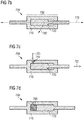
- Figs. 5a and 5b show a potential application of such a hinge-like support element 400 in an embodiment of an inventive sole 500 . Only a midsole 550 is schematically shown in whose forefoot region such a hinge-like support element 400 is arranged.
- the hinge axis of the support element 400 may, in particular, be arranged in the region below the toe joints, running from the medial side to the lateral side.
- Fig. 5a shows the sole 500 during initiation of the final phase of the step cycle and Fig. 5b shows the sole 500 during push-off over the toe region at the end of the step cycle.
- the wings of the hinge of the support element 400 can stabilize the forefoot region and thus prevent twisting ones ankle and function as a push-through protection, e. g. to protect the foot of the wearer from pointed objects, etc., during treading down or push-off.
- Figs. 15a -k show schematic sketches of possible embodiments of inventive support elements, which may, for example, be provided hinge-like. These sketches are primarily intended to provide the skilled person with an idea about the scope of application of the present invention and do not necessarily represent the proportions and dimensions encountered in an actual embodiment. The same applies to the sketches in Figs. 16a -q, 17a-e, 18a-h, 49a-d and 20a-b.
- a support element may e.g. be used to provide a collapsible shoe structure to minimize the required package space, cf. Fig. 15a .
- a support element may also be utilized, e.g. in a basketball shoe to equalizing dynamic movements and to avoid spraining or ankle twist, cf. Figs. 15b and 15c .
- Support elements may also be used to control shear movements of the sole material, cf. Fig . 15d .
- Fig. 15e shows how a support element may be used to restrict or support bending in a certain direction or define flex areas (here flexing in the area of the joint).
- Fig. 15f shows a further embodiment of a hinge-like support element arranged in the heel region of a sole.
- the hinge may help to shorten the lever arm and depending on its position to decrease the angular velocity in the frontal (pronation or supination velocity) or sagittal plane (sole angle velocity).
- the hinge can be constructed to limit the amount of rotation and it may help providing better heel lock-down, i.e. the heel may move with the bottom unit of the sole and hence the sole does not try to pull off the foot.
- Fig. 15g shows how a hinge-like support element comprising two plates connected via a hinge, which is embedded within the midsole may provide a banking support to a foot e.g. during lateral side-cut movements.
- the support element could have a more flexible arm and a stiffer arm to guide the foot into a preferred position.
- Figs. 15h -j illustrate how a support element may be used to provide shock absorption and / or improved energy return to the wearer.
- the embodiment shown in Fig. 15i may provide extra energy return due to the additive mechanical construction. This construction may also work for a banking support as discussed above.
- the support element shown in Fig. 15j comprises a predefined angle to support the foot in lateral sports in side movements.
- Fig. 15k shows how a support element may be used to vary the height of the heel portion of a sole or shoe, e.g. to provide an embedded claiming aid.
- Figs. 6a to 6c show a further embodiment of an inventive support element 600 .
- the support element 600 is provided slider-like. It comprises a first partial member 610 , which is provided as a slider, and a second partial member 620 , which is provided as a frame in which the first partial member 610 can be slid along.
- the first partial member 610 was injection molded from polyamide 6.6 with a lubricant added and the second partial member 620 was injection molded from polyamide 12 in two injection molding steps as already described above. Furthermore, the first partial member 610 was slidably connected in two connection regions 630 and 635 with the second partial member 620 in the second injection molding step.
- any combination of Options I, II and III discussed above might also be used.
- connection regions 630 and 635 are provided such that the first partial member 610 comprises a respective groove on two opposite sides, in which corresponding protrusions or ridges of the second partial member 620 are arranged, such that the first partial member 610 may be slid along these protrusions or ridges.
- Fig. 6a shows the slider 610 in a first position at the top edge of the support element 600
- Fig. 6b shows the slider 610 in a second position at the bottom edge of the support element 600.
- Fig. 6c shows a side view of the support element 600 .
- the first partial member 610 further comprises a cylindrically formed protruding element 640 , which may, for example, facilitate anchoring of the first partial member 610 in the midsole.
- Figs. 16a -q show schematic sketches of possible embodiments of inventive support elements, in particular of possible slider-like embodiments.
- a slider-like support element may, e.g. be used as a clima-switch, Fig. 16a . By moving a slider left to right either an opening arise the opening is closed thus allows ventilation when opened.
- a slider-like support element may also be used to adjust the forefoot or heel in a certain angle to customize the shoe to the foot or the preferred movement (specific sport or terrain), cf. Fig. 16b .
- Such a support element could be movable during walking or be fixable in different positions.
- the flexibility of the shoe may also be adjusted, e.g. by changing the flex groove length by a slider-like support element, cf. Fig. 16c .
- a slider-like support element could be used for storing valuable things like keys e.g. during running or could provide housing for an electronic device, cf. Fig. 16e .
- Traction elements could be allowed or restricted from coming out the bottom surface during walking by a slider-like support element, cf. Fig. 16f .
- the height of the heel of a shoe could be adjusted with the simple adjustment of two elements, one of which may be wedge-shaped, which could be slid towards or apart from each other, cf. Fig. 16g .
- a cleat for cycling could be embedded and be slidable in its position, preferable in the direction from the heel to forefoot but also in a direction from the medial side to the lateral side or also regarding its depth within the midsole, cf. Fig. 16h .
- An arch support could be placed as preferred or move with the foot during walking or running as shown in Fig. 16i .
- the stiffness of the midsole could be adjusted by sliding elements, similar to a bedframe or by sliding the elements to the side which should be the stiffest, cf. Fig. 16j .
- the size of a shoe may be shifted between a range of e.g. UK 40-43 or tolerances in the size may be allowed to allow relative movement between the forefoot and heel, cf. Fig. 16k .
- a slider-like support element may also serve to alleviate contact forces in the heel region during impact of the foot with the ground, cf. Fig. 16l (this concept is further discussed in relation to Figs. 11a -b below).
- Fig. 16m illustrates a further possibility how a slider-like support element may be used to control the stiffness of a sole.
- Fig. 16n illustrates yet a further possibility how a slider-like support element may be used to control the stiffness of a sole by use of a pair of adjustable prongs that may be positioned parallel or vertical to the surface of the sole.
- Fig. 16o shows how having a sliding element within an embedded element, the stiffness, orientation or shape of the embedded element could be adjusted.
- Fig. 16p illustrates the concept of having a rigid bar which could be covered by an softer part and be able to move relative to the bar, in order to have more durable elements, e.g. elements that could bend more and be thinner.
- Fig. 16q shows how stretch of the sole material in medial to lateral direction could be restricted in defined areas by a bar movable within a housing in the longitudinal direction from the heel to the toes.
- Figs. 7a - 7g show an embodiment of an inventive support element 700 which comprises a connection region 730 .
- a first partial member 710 was slidably connected to a second partial member 720 in an injection molding process.
- the connection region 730 is provided by the first partial member 710 comprising a cylinder and the second partial member 720 comprising a piston, which is arranged in the cylinder of the first partial member 710 .
- the opposite case is also possible, however.
- the first partial member 710 and the second partial member 720 may further each comprise a rod-shaped section which runs into the cylinder or the piston, respectively.
- the first partial member 710 may, for example, be injection molded from a first plastic material, whereas the second partial member 720 maybe injection molded from a second plastic material, e.g. according to Options I, II and / or III as discussed above.
- the second partial member 720 may be slid along the free direction 770 within the cylinder of the first partial member 710 a certain distance, that is until the piston hits one of the respective ends of the cylinder of the first partial member 710 , as e. g. illustrated in Figs. 7a and 7b .
- the free direction 770 is, as depicted in Figs. 7a and 7b , the cylinder- / piston axis.
- a locking direction 780 which runs perpendicular to the free direction 770 , essentially (i. e. apart from tolerances due to the manufacturing process) no translations of the piston with respect to the cylinder and therefore of the second partial member 720 with respect to the first partial member 710 are possible (they are, in any case, more strongly restricted than in the free direction 770 ).
- rotations of the piston with respect to the cylinder around the free axis 770 are also possible.
- the cylinder and the piston are, for example, provided with a rectangular cross-section, such rotations are not possible.
- rotations of the first partial member 710 with respect to the second partial member 720 around the locking axis 780 which is perpendicular to the free axis 770 , are essentially not possible.
- such a translation of the piston of the second partial member 720 (indicated by the arrows 721 and 722 ) in the cylinder of the first partial member 710 can, for example, be used to create a pumping action.
- the cylinder of the first partial member 710 may, for example, comprise an inlet 750 , through which a liquid and / or a gas 760 may be sucked into the cylinder (indicated by the arrow 701 ) and be pushed out of the cylinder again (indicated by the arrow 702 ).
- the illustrations in Figs. 7c to 7e are merely schematic illustrations, which do not serve the purpose to represent the pumping mechanism in all details. This pumping mechanism will be suitably chosen by the skilled person, for example taking into consideration the manufacturing expenses.
- Figs. 7f and 7g show, for example, how such a pumping mechanism might be used to move back and forth a liquid and / or a gas 760 in a system of bladders 751 and 756 connected to each other.
- the bladders 751 and 756 may be connected by means of feeding lines with corresponding in- and outlets 750 and 755 in the cylinder of the first partial member 710 , such that by a movement of the piston of the second partial member 720 the liquid or the gas 760 , respectively, may be pumped from one bladder to the other.
- FIGs. 7f and 7g are merely schematic illustrations, which cannot show all details of such a system of connected bladders.
- a support element like the support element 700 shown here may also act as a "passive" element, for example as some kind of valve, which directs and controls a liquid or gas stream in such a system of connected bladders, instead of actively pumping the liquid and / or gas 760 through the system.
- a support element 700 is arranged in a midsole 850 of an embodiment of an inventive sole 800 in such a way, that the pumping action is created during walking with the sole 800.
- the lifting of the heel (cf. arrow 801 ) during push-off over the tip of the foot at the end of a step cycle may have the effect that the cylinder of the first partial member 710 moves (cf. arrow 802 ) with respect to the piston of the second partial member 720 in comparison to the "neutral" position of the sole 800 as shown in Fig. 8a , and hence creates the pumping action.
- a system of connected bladders 751 and 756 may also be arranged in the midsole 850 , for example, as discussed in relation to Figs. 7f and 7g .
- Figs. 17a -e show further schematic sketches of possible embodiments of inventive support elements, e.g. embodiments comprising a piston and cylinder or a grommet and rivet.
- Fig. 17a shows how shear pots may be used to prevent excessive shearing of the sole.
- Fig. 17b shows how a piston and cylinder construction may be used to prevent an overstretching of the sole.
- Fig. 17c illustrates the possibility of having several cylinder/piston units arranged in series along a common connection member.
- Fig. 17d illustrates how two screwable sleeves may be tightened or loosened to increase or decrease the stiffness of the sole material.
- Fig. 17e shows how a grommet and rivet construction may be used to provide a traction element which extends through the bottom surface of the sole.
- Figs. 9a to 9c show further conceivable embodiments of an inventive support element 900 with a first partial member 910 and a second partial member 920 which were rotatably connected to each other in a connection region 930 in an injection molding process.
- the connection region 930 is provided as a ball joint.
- first partial member 910 and the second partial member 920 each comprise a rod-shaped section which runs into the connection region 930.
- the free axis 970 which may, for example, as depicted in Figs. 9a to 9c , be given by a longitudinal axis through the support element 900 and, in particular, the rod-shaped sections of the first partial member 910 and the second partial member 920 , rotations of the second partial member 920 with respect to the first partial member 910 with arbitrary rotation angles may be possible.
- rotations around the axis 970 may, in principle, also be limited.
- rotations of the second partial member 920 with respect to the first partial member 910 may be more strongly restricted or be completely excluded. This may depend on the way in which the first partial member 910 is designed in the connection region 930.
- the first partial member 910 encompasses the second partial member 920 in the connection region 930 to such a degree, that essentially no backlash is present in the connection region 930 , a rotation of the second partial member 920 with respect to the first partial member 910 around the locking axis 980 is essentially not possible.
- the connection region 930 comprises a mouth 935 , rotations of the second partial member 920 around the locking axis 980 are possible until the second partial member 920 hits an edge of the mouth 935 .
- the mouth 935 may be provided symmetrically, for example circular, such that rotations of the second partial member 920 with respect to the first partial member 910 around a second locking axis (not shown), which is perpendicular to the first locking axis 980 and the free axis 970 , are possible to the same degree as rotations around the first locking axis 980 .
- the mouth 935 may, however, also be designed asymmetrically, such that rotations around the first locking axis 980 and around the second locking axis are possible or restricted to different degrees.
- Figs. 10a and 10b show a further conceivable embodiment of an inventive support element 1000 , wherein a first partial member 1010 was rotatably connected to a second partial member 1020 in an injection molding process in a connection region 1030.
- the connection region 1030 is provided as a ball joint.
- the first partial member 1010 was manufactured from polyamide 6.6 with a lubricant added and the second partial member 1020 from polyamide 12 in two injection molding steps as already discussed.
- a lubricant added and the second partial member 1020 from polyamide 12 in two injection molding steps as already discussed.
- other material combinations as described herein and, in particular, any combination of Options I, II and III discussed above might also be used.
- rotations of the first partial member 1010 with respect to the second partial member 1020 are possible with arbitrary rotation angles.
- rotations around this free axis 1070 may also be limited.
- a locking axis 1080 that is perpendicular to the free axis 1070 rotations of the first partial member 1010 with respect to the second partial member 1020 are only possible up to a threshold angle ⁇ , as shown in Fig. 10b .
- the value of this threshold angle ⁇ is determined by the size and design of the mouth 1035 of the ball joint 1030.
- Figs. i8a-h show further schematic sketches of possible embodiments of inventive support elements.
- Fig. 18a which shows an embodiment similar to the support element 100 , illustrates how the rotational range of such a support element may be controlled.
- Fig. 18b shows an embodiment comprising two ball joints that may comprise a limiter, respectively, which limits the rotational range in the two connection regions.
- the joint connecting the two ball joints may be convoluted.
- the rear plate of the support element may also extend as an external heel counter.
- Fig. 18c shows how a translational movement in a support element may be used to allow or restrict rotational movements within the support element by two sets of engaging teeth.
- This construction might be used to increase the torsion stiffness during dynamic movements when the teeth engage due to the translational movement within the support element, whereas, when the sole lies flat on the ground, the teeth disengage and allow twisting of the sole and the support element.
- Fig. 18d illustrates the idea of having an imbedded momentum generated within the sole.
- Fig. 18e illustrates how a support element could be adjusted, e.g. in height, from a bottom or top surface of the midsole by different interaction elements, like locks, screws or hinges.
- Fig. 18f shoes how a rotating internal disc may be used to open and close claim vents within the shoe sole.
- Fig. 18g illustrates how a support element may comprise a snap-fit connection that was overmolded in an injection molding process.
- Fig. 18h shows an embodiment that may allow or restrict a rotating only in a certain flex angle of the foot.
- Figs. 11a and 11b show a further embodiment of an inventive support element 1100 as well as an embodiment of an inventive sole 1199 which comprises such a support element 1100.
- the support element 1100 comprises a first partial member 1110 and a second partial member 1120, which are slidably connected with one another in an injection molding process in a connection region.
- the first partial member 1110 and the second partial member 1120 are provided as planar members.
- the first partial member 1110 and the second partial member 1120 are arranged with respect to each other such that their respective planar surfaces face each other.
- both partial members 1110, 1120 may be slid along their planar surfaces with respect to each other.
- the second partial member 1120 may, for example, as shown in Fig. 11a , be provided as some kind of carriage, which encompasses the first partial member 1110 which is provided as a plate along its longitudinal sides in such a way, that it can slide along the planar surface of the first partial member 1110 in a longitudinal direction.
- such a support element 1100 may, for example, be arranged in the heel region of a midsole 1150 in such a way, that translations of the first planar partial member 1110 relative to the second planar partial member 1120 may proceed in a plane of the sole 1199 and essentially in longitudinal direction of the sole 1199, as indicated by the arrows 1101, and may thus at least partially absorb or alleviate shear forces that may act on the musculoskeletal system of the wearer when treading down with the heel.
- Figs. 12a and 12b show further conceivable embodiments of inventive support elements 1200a and 1200b, each comprising a plurality of first partial members and / or second partial members that are movably connected to each other in respective connection regions.
- the support element 1200a comprises two first partial members 1210a and 1211a as well as two second partial members 1220a and 1221a.
- the first and second partial members 1210a, 1220a, 1211a, 1221a are alternatingly movably connected to each other in connection regions 1230a, 1231a, 1232a, wherein these connections were created in an injection molding process, e.g. according to Options I, II and / or III as discussed above.
- the connection regions 1230a, 1231a and 1232a are provided as ball joints, such that rotations of the first partial members 1210a, 1211a with respect to the second partial members 1220a, 1221a are possible.
- the support element 1200b comprises a central second partial member 1220b, with whom a plurality of first partial members 1210b, 1211b, 1212b, 1213b, 1214b and 1215b were rotatably and / or slidably connected in a plurality of connection regions 1230b, 1231b, 1232b, 1233b, 1234b and 1235b in an injection molding process, e.g. according to Options I, II and / or III as discussed above.
- the connection regions 1230b, 1231b, 1234b and 1235b are provided as ball joints in the case shown here, whereas the connection regions 1232b and 1233b comprise a piston and cylinder.
- Figs. 19a -d show further schematic sketches of possible embodiments of skeleton-like inventive support elements.
- the central element could be rigid or flexible.
- the articulated elements connected to the central element can rotate or move sideways to give the sole movement stability / flexibility in certain directions.
- a skeleton-like support element can be provided as an internal skeleton element with articulated elements within a midsole, cf. Fig. 19b .
- the skeleton-like support element comprises blocks of midsole material arranged at the ends of the articulated elements of the support element, cf. Fig. 19c .
- Fig. 19d shows a further possible arrangement of the connection regions of such a skeleton-like support element.
- a first partial member 1310 may, e. g. as shown in Figs. 13a and 13b , be connected movably, in particular rotatably and / or slidably, with a second partial member 1320 by injection molding, indicated by the arrow 1350 , in a connection region 1330.
- the first partial member 1310 may, for example, be positioned in a mold 1360, which may, for example, be comprised of two mold parts 1361 and 1362 movable with respect to each other. Subsequently, the mold 1360 may be closed, and the second partial member 1320 may be manufactured by the injection molding process 1350 in the closed mold 1360, wherein the mold 1360 or the two mold parts 1361 and 1362, respectively, may be provided to comprise a cavity 1321 in the closed state that corresponds to the shape of the second partial member 1320 to be manufactured and that is filled during the injection molding process 1350 by the material used for the manufacture, hence creating the second partial member 1320 and simultaneously connecting it in the connection region 1330 movably, in particular rotatably and / or slidably, with the first partial member 1310.
- the first partial member 1310 is also injection molded in an injection molding process in the mold 1360 as shown in Fig. 13c and indicated by the arrow 1351.
- the mold 1360 or the mold parts 1361 and 1362, respectively may comprise a further cavity 1311 in a second closed state of the mold 1360 that may differ from the closed state of the mold 1360 in which the second partial member 1320 is molded, wherein the cavity 1311 corresponds to the shape of the first partial member 1310 to be manufactured and which is filled by the material used for the manufacture during the injection molding process 1351.
- the processing parameters and in particular the molding temperature and the different mold positions may have to be adjusted when injection molding the first and second partial member, respectively. This may in particular be the case, if the materials for the first and second partial member are chosen according to Option II as discussed above.
- the first partial member 1310 may also be injection molded in a different mold and then be inserted into the mold 1360.
- the second partial member 1320 is initially positioned in the mold 1360 or injection molded in this mold, and in a further injection molding process the first partial member 1310 is subsequently manufactured in the mold and connected movably, in particular rotatably and / or slidably, in the connection region 1330 with the second partial member 1320.
- the mold 1350 may, for example, be a rotational mold, but different kinds of molds are also possible.
- Figs. 14a and 14b illustrate a further embodiment of an inventive manufacturing method 1400 for the manufacture of an inventive support element.
- the first partial member 1410 and the second partial member 1420 are manufactured in a mold 1460 and connected movably, in particular rotatably and / or slidably, in a connection region 1430 by a simultaneous injection molding, indicated by the two arrows 1450.
- the mold 1460 may comprise two mold parts 1461 and 1462 movable with respect to each other, which may be provided such that in the closed state of the mold 1460 they comprise cavities 1411 and 1421 that correspond to the shape of the first partial member 1410 and the second partial member 1420 , respectively, to be manufactured and that are filled with the material used for the manufacture during the injection molding process 1450 , thereby creating the first partial member 1410 and the second partial member 1420 and simultaneously connecting them movably, in particular rotatably and / or slidably, in the connection region 1430 .
- This embodiment of an inventive method may in particular be applied if the materials for the manufacture of the first and second partial member, respectively, are chosen in accordance to Option I and / or Option III discussed above.
- FIGs. 13a , 13b and 13c are merely sketches and that, in particular, the specific design of the support elements shown there may not be construed as limitations to the methods 1300 , 1400 being described, which may be used for the manufacture of any kind of inventive support element.
- Figs. 20a -b show schematic sketches of possible embodiments of inventive support elements for use with a lacing system of a shoe.
- Fig. 20a shows how a support element may be used to provide an embedded lace locking system.
- Slidable lace attachment members may be connected with an elastic connection or a spring connection to provide a good fit of the laced shoe.
- Fig. 20b illustrates the concept of bundling the lace force in one point for getting a comfort and compressed fit around the midfoot by a lace closure system, e.g. at the bottom or the side of the midsole.
Abstract
Description
- The present invention relates to a support element for the sole of a shoe, in particular a sports shoe, a sole as well as a shoe with such a support element and a method for the manufacture of a support element.
- The design of a shoe sole renders it possible to provide a shoe with a plethora of different properties, which may be pronounced to different degrees depending on the kind of shoe. Primarily, shoe soles serve protective functions. They protect the foot from injury by their increased hardness compared to the shoe shaft, for example caused by pointed objects on which the wearer may tread. Furthermore, the shoe sole usually protects the shoe from excessive wear by an increased abrasion resistance. Shoe soles may also increase the grip of a shoe on the respective ground. Further functions of a shoe sole may be to provide a certain stability to the course of movements. In addition, a shoe sole may provide a damping action to cushion the forces occurring during contact of the shoe with the ground. Finally, a shoe sole may also protect the foot from dirt or spray water or provide a plurality of further functionalities.
- To meet this plurality of requirements, which arise from the above mentioned exemplary functions, many different materials for the manufacture of shoe soles are known from the prior art. As examples for these different materials, ethylene-vinylacetate (EVA), thermoplastic polyurethane (TPU), rubber, polypropylene (PP) or polystyrene (PS) shall be mentioned here. Furthermore, the use of expanded materials, in particular expanded thermoplastic polyurethane (eTPU) or expanded polyether-block-amide (ePEBA), were considered for the manufacture of a shoe sole. Expanded TPU and expanded PEBA distinguish themselves by a low weight and good elasticity- and damping properties.
- For example, the
WO 2005/066250 A1 describes a sole made from expanded thermoplastic polyurethane, which may be connected with a shoe shaft without an additional bonding agent. TheDE 10 2012 206 094 A1 andEP 2 649 896 A2 - Further prior art is disclosed in
US 2012 / 0 047 770 A1 ,US 2011 / 0 302 805 A1 ,US 2010 / 0 122 472 A1 ,US 2003 / 0 131501 A1 ,DE 10 2008 020 890 A1 , the publication "Der richtige Dreh (Teil 1) - Kennwertermittlung für das Montagespritzgießen" of the magazine Kunststofftechnik, 2008, p. 1 - 8, and the handbook "Sächtling Kunststoff Taschenbuch", Hanser Verlag. 31th edition, 2013, p. 287. - To selectively influence the properties of the sole, the use of additional functional elements, as for example a reinforcing element or a support element, is known from the prior art. Such a reinforcing- or support element can increase the stability of the sole in chosen regions, like, for example, the medial region of the midfoot, and can serve to relief the musculoskeletal system, for example during running on uneven terrain or when over-pronating.
- A disadvantage of the reinforcing- and support elements known from the prior art is, however, that they are typically integrally molded or formed from a single base material. Hence, the flexibility- and deformation properties of the reinforcing element are already determined throughout the entire reinforcing element to large degrees by the selection of the base material. Also, the number of possible functions that can be assumed by such a reinforcing element is limited.
- It is therefore a problem underlying the present invention to provide support elements for soles of shoes and methods for their manufacture that further increase the possibilities to influence the properties of a sole. Herein, the manufacture shall involve as small a number of individual manufacturing steps as possible and as little manufacturing expenses as possible.
- According to an aspect of the present invention, this problem is at least partially solved by a support element for a shoe sole or for a cushioning element, which comprises a first partial member and a second partial member, wherein the second partial member is rotatably and / or slidably connected with the first partial member in a connection region by an injection molding process.
- The support element may, for example, allow locally influencing the elasticity-, flexibility- and deformation properties of the sole as desired. Due to the rotatable and / or slidable connection of the first partial member with the second partial member, the possibilities of influencing the properties of the sole by use of the support element may be significantly increased in comparison with an integrally molded support element. It is, for example, possible to influence the flexibility of the sole independently of the torsion stiffness of the sole in different regions of the sole. The rotatable and / or slidable connection may, in particular, be arranged in regions of the sole in which an increased movability of the sole shall be maintained. A rotatable and / or slidable connection may, for example, be arranged in the forefoot region, in which the sole shall comprise a sufficient degree of flexibility along its longitudinal direction in order to not impair roll-off of the foot over the toes. In the midfoot region or in the toe region, it may be advantageous if the sole is provided relatively stiff, to prevent injuries of the wearer. An inventive support element may thus allow providing relatively stiff and stable regions of the sole which may be separated from one another by a flexible part of the sole. With an integrally formed support element without a rotatable and / or slidable connection of two partial members, this may be hard to achieve, if at all possible.
- In the following, further design possibilities and optional features of inventive support elements are described, which may be combined by the skilled person as desired to achieve the respective desired effect with regards to influencing the properties of the sole.
- The first partial member may comprise a first plastic material and the second partial member may comprise a second plastic material, wherein the two plastic materials are chosen such that the connection region does not comprise a chemical bond of the two materials.
- By such a choice of the first and second plastic material, the support element may be manufactured in a simple injection molding process in such a manner that the first and the second partial members comprise the rotatable and / or slidable connection, without subsequent method steps being necessary for this like, for example, a subsequent bonding, clipping together, e.g. in a snap-fit manner, or different kind of assembling of the first and second partial members. This may increase durability of the rotatable and / or slidable connection significantly and simplify the manufacture. This may also mean that the typical tolerances that might be needed with snap-fit pieces may not have to be observed. This can lead to more consistent pieces and "perfect fit and function".
- Herein, the first plastic material and the second plastic material maybe chemically incompatible. This will be referred to in the following as "Option I".
- Due to the use of such incompatible plastic materials, no additional measures must be taken during the manufacture to avoid gluing, melting together or the creation of another kind of chemical bond between the two plastic materials. It is, for example, possible that the first plastic material comprises or consists of a polyamide and the second plastic material comprises or consists of polyoxymethylene (POM) (or vice versa). The POM maybe overinjected over the polyamide, wherein due to the chemical incompatibility of the two materials, no chemical bond forms in the connection region.
- It is also possible that the first plastic material has a first melting temperature that is significantly higher than a second melting temperature of the second plastic material (or vice versa). This will be referred to in the following as "Option II".
- It is then possible that the first plastic material is overinjected with the second plastic material at a temperature lower than the first melting temperature. In this way, no chemical bond is created in the connection region as the first material does not melt during overinjection with the second material. It is, for example, possible that the first plastic material comprises or consists of a polyamide 6.6 (PA6.6) with a melting temperature of around 260 °C, which is overinjected with the second plastic material that comprises or consists of a polyamide 12 (PA12) with a melting temperature of around 180 °C (or vice versa), wherein the overinjection is performed at a temperature below 260 °C but preferably higher than 180 °C.
- It is furthermore possible that the first and second plastic material do not for a chemical bond in the connection region due to an additive contained in either or both of the first and / or second plastic material. This will be referred to in the following as "Option III".
- This may allow broadening the range of materials that may be used as first or second plastic material, respectively, while still guaranteeing the creation of the rotatable and / or slidable connection of the first and second partial members. The first plastic material could, e.g. comprise a polyamide that is modified with lubricant, for example a polyamide modified with polytetrafluoroethylene (PTFE), and the second plastic material could comprise or consist of an unmodified polyamide (or vice versa). The second plastic material could then e.g. be overinjected over the first plastic material, wherein due to the added lubricant in the first plastic material, no chemical bond forms in the connection region.
- It is mentioned here, that Options I, II and III can also be combined with one another in a given embodiment of an inventive support element.
- The first plastic material may, for example, comprise one or more of following materials: polyamide (PA), in particular polyamide-6.6 (PA6.6), polytetrafluoroethylene (PTFE).
- The second plastic material may, for example, comprise one or more of the following materials: polyamide (PA), in particular polyamide-12 (PA12), polyoxymethylene (POM), polytetrafluoroethylene (PTFE).
- These materials are well suited for the manufacture of a support element, because they are easily processed and cheap and can meet the typical requirements of such support elements with respect to their flexibility- and elasticity properties. Herein, the selection of the first plastic material and the second plastic material may be carried out in such a way that during the injection molding no chemical bond is formed between the first and second plastic material in the connection region, as mentioned above.
- Moreover, when used in cushioning elements or soles for shoes (cf. below), in particular in midsoles or parts of midsoles, such support elements can have a complex structure without being locked into the cushioning element or sole. The material of the support element in contact with the material of the cushioning element or sole can be incompatible to the material of the cushioning element or sole, so that the support element is surrounded or partially surrounded by the cushioning element or sole, but does not stick or bond to it. In particular, no chemical bond is created. This may be beneficial, for example to allow the support element to move with the material of the cushioning element or sole. The interaction of the support element and the cushioning element or sole may thus be optimized. The support element can react to stretch, twist and compression movements of the cushioning element or sole. Therefore, the support element can control and optimize the movement of the cushioning element or sole.
- In some embodiments, the cushioning element can be changed in its position within the sole. It can e.g. be moved sideways or flipped in its horizontal or vertical direction to change the properties of the sole comprising the cushioning element.
- A support element might also be embedded within a cushioning element or sole and have an adjustment device facing to one surface of the cushioning element or sole. Hence, the element may be adjusted individually by a wearer.
- In this regard, in particular cushioning elements and soles made of particle foams (cf. below) provide another benefit for such embedded support elements. The support elements can be placed in a mold for creating the cushioning element or sole, which at least partially surrounds the support element (cf. also below). The particles used in this process may be inserted as solid expanded particles into the mold. Only the surface of the particles may then be melted for creating the particle foam and hence the cushioning element or sole. Therefore, there will be no liquid material present within the mold during the manufacture which could flow into the support element and lock it its position or prevent or limit the movement in certain positions by blocking the movable connections or the like. It is therefore possible to embed support elements with very complex structures.
- It is furthermore conceivable that the support element comprises at least one locking direction, in which locking direction a translation of the first partial member relative to the second partial member is more strongly restricted than in another direction. This other direction will be designated as free direction in the following.
- In this way, it is, for example, possible to influence the properties of the sole to the effect that material compressions, material elongations or shearing movements in the locking direction are decreased in comparison to the free direction and that the sole therefore appears stiffer or more stable, respectively, in the locking direction than in the free direction. Herein, this free direction may, for example, be perpendicular to the locking direction or it may be aslant to it. It is, in particular, conceivable that the shearing ability or compressibility under translations in the locking direction initially comprises a first, smaller value and only for translations above a certain threshold value comprises a second, larger value. In this manner, excessive shearing of the sole may be avoided or limited, for example to avoid injuries caused by an excessive destabilization of the foot.
- It is also possible that the support element comprises at least one locking axis, around which locking axis a rotation of the first partial member is more strongly restricted than a rotation around another axis. This other axis will be designated as free axis in the following.
- This may have the effect that the torsion stiffness of the sole around the locking axis is larger than the torsion stiffness around the free axis. Also here, it is possible that for twisting around the locking axis, the torsion stiffness initially comprises a first, smaller value and only for a twist above a certain threshold angle comprises a second, larger value. In this manner, excessive twisting of the sole around the locking axis may be avoided or limited, which may otherwise lead to injuries.
- In this case, too, the free axis may, for example, be perpendicular to the locking axis or it may be aslant to it. In particular, the locking axis may be oriented in a direction from the heel of the sole to the tip of the foot, such that the torsion stiffness of the sole with respect to this longitudinal axis is higher than a torsion stiffness of the sole with respect to a free transversal axis from the medial to the lateral side of the sole. Or the reverse situation may be the case, i. e. the locking axis runs in medial-lateral direction.
- The free (transversal) axis may, in particular, run beneath the toe joints from the medial side of the sole to the lateral side of the sole, whereas the locking axis runs from the heel to the tip of the foot. This may allow providing a sole which is sufficiently flexible in the region of the toe joints to enable a natural roll-off of the foot and at the same time comprises a sufficiently high torsion stiffness around its longitudinal axis to prevent a twisting of ones ankle or a breaking out of the foot of a wearer.
- In this regard, a support element that is provided hinge-like may, for example, also be conceivable, whose free hinge axis runs beneath the toe joints from the medial to the lateral side. Around this hinge axis, rotational motions of the hinge are easily possible, that is the sole facilitates roll-off of the foot. Rotations of the first and second wing of the hinge around another axis, for example around a locking axis arranged perpendicular to the hinge axis (for example, around the longitudinal axis of the sole) are essentially not possible.
- The connection region may, for example, be provided as a ball joint.
- A ball joint allows providing a connection region which allows a large degree of mobility and, in particular, rotational movements between the first and second partial members. Hence, such a ball joint may be employed in regions in which the sole shall be "movable". In combination with the locking axis it is, however, also possible with a connection region provided as a ball joint to control or influence the torsion stiffness of the sole around different axes independently from one another, for example.
- The connection region may also comprise a piston and cylinder, in which cylinder the piston is arranged.
- Connection regions provided in this manner may, for example, have the effect that the bending capabilities of a sole with such a support element can be reduced along the piston- and cylinder axis, i. e. the sole becomes stiffer along this axis, whereas the torsion stiffness around this axis is essentially left unaffected. Such a cylinder construction may also allow leaving shearing- or compression movements of the sole material along the cylinder axis initially unaffected, until a situation arises in which the piston hits an edge of the cylinder.
- It is furthermore conceivable that the connection region is provided such that a movement of the first partial member relative to the second partial member creates a pumping action. Herein, the support element may be provided such that the movement of the first partial member relative to the second partial member is created by walking with the shoe sole.
- Such a pumping action, in particular if this action is created by walking with the shoe sole, may be employed to transport air into the inner part of the shoe or out of it and therefore increase the ventilation of the inner part of the shoe and therefore of the foot. This may increase wearing comfort, in particular during longer wear of the shoe. It is, however, also possible that by means of the pumping action, a liquid is moved between different regions of the inner parts of the sole. The action may, for example, serve to transport a liquid from a first liquid bladder in a first region of the sole into a second liquid bladder in another region of the sole.
- Instead of being provided to actively conduct such a pumping action, the support element may, in principle, also be provided in such a manner, that it acts as a valve to regulate such a liquid- or airstream.
- It is also possible that the first partial member and / or the second partial member are provided as planar members.
- A support element provided in a hinge-like manner and the possibilities for using such a support element have already been indicated. In general, partial members provided as planar members may allow influencing the properties of the sole and, in particular, its bendability / flexibility in (large) planar regions, to obtain a sole whose properties may be relatively constant across these planar regions. It can, for example, be desirable that the flexibility- and elasticity properties of the sole are uniformly influenced in the region of the toes, in the midfoot region, or in the heel region, to achieve a pleasant wearing sensation. Partial members provided in such planar manner may also act as a push-through protection, for example beneath the forefoot or the heel, to prevent injuries caused by pointed objects, etc., during treading down or push-off of the foot and to facilitate a secure wearing sensation.
- Herein, the first planar member and the second planar member may be provided slidably with respect to each other.
- It is, in particular, possible that the first planar member and the second planar member are facing each other with their planar surfaces, with it also being possible that there is some interspace between the first and the second planar member that may be filled with a material like a gel or a liquid, and that the planar members may be slid relative to each other along the planar surfaces. Such a construction may, for example, be used in the heel region, to alleviate shearing forces acting on the musculoskeletal system of the wearer when treading down, as for example described in the documents
DE 102 44 433 B4 andDE 102 44 435 B4 . - The first partial member and / or the second partial member may also comprise a rod-shaped section, which runs into the connection region.
- Such rod-shaped sections may have the advantage that they take up a relatively small volume of the sole and therefore do not markedly influence the damping properties and damping capabilities of the sole. This may also mean saving weight compared to partial members provided in a different manner. At the same time, the rod-shaped sections may serve to increase the bending stiffness of the sole along an axis of the rod-shaped section, for example.
- It is furthermore possible that the first partial member is connected rotatably and / or slidably with a plurality of second partial members in a plurality of connection regions by an injection molding process.
- Here, the first partial member may act as a central partial member that is, for example, arranged in the middle of the sole, to provide the midfoot region and, in particular, the region of the arch of the foot with the desired stability. The second partial members connected rotatably and / or slidably with the first partial member may, for example, extend from this central first partial member in the direction of the edges of the sole, the tip of the foot, or the heel, in order to influence the stability- and elasticity properties of the sole in these regions as desired.
- It is, in particular, possible that the first partial member and the plurality of second partial members form a skeleton-like structure within the sole, which allows influencing the properties of the sole in all or at least predominant parts of the sole. If the first and the plurality of second partial members are in addition (at least partially) provided rod- shaped, this may happen without significantly compromising the weight or the damping properties of the sole.
- The opposite situation, in which the second partial member is connected rotatably and / or slidably with a plurality of first partial members in a plurality of connection regions by an injection molding process, is also conceivable.
- It is, in particular, conceivable that a plurality of first partial members and a plurality of second partial members are alternatingly connected to each other rotatably and / or slidably in a plurality of connection regions.
- It is hence possible to provide support elements that comprise a chain-like, skeleton-like or mesh-like structure and hence to influence the properties of the sole in numerous ways, selectively in specific parts of the sole or throughout the entire sole area.
- Another aspect of the present invention relates to a cushioning element, in particular a midsole or part of a midsole, with an inventive support element. Herein, the cushioning element may comprise randomly arranged particles of an expanded material, for example of expanded thermoplastic polyurethane (eTPU) and / or expanded polyether-block-amide (ePEBA). The randomly arranged particles may be fused at their surfaces, for example by subjecting the particles to a heat, steam and / or pressure treatment within a mold, or the like.
- Further aspects of the present invention relate to a sole with an inventive support element as well as a shoe, in particular a running shoe, with such a sole or cushioning element.
- An inventive sole may, for example, comprise or be formed by a cushioning element, in particular a midsole, with a support element as discussed above. The support element could, however, also be part of a sole that does not comprise such a cushioning element.
- For the sake of conciseness, reference is always made to a shoe sole in the following. However, if applicable, the case of an individual cushioning element is always also implied.
- For such a sole or shoe, it is possible within the scope of the invention to combine the discussed design possibilities and optional features of an inventive support element in any order, and it is also possible to leave out certain aspects, if these should appear dispensable for the respective shoe or the respective sole.
- Explicit reference is furthermore made to the fact that embodiments of an inventive sole or an inventive shoe may comprise further elements, in particular three-dimensionally formed elements, in addition to an inventive support element, like for example: stabilizing elements, support elements, in particular elements providing a banking support to the foot during lateral side-cut movements, elements to improve breathability, elements to improve the grip of the sole / shoe on the ground, further cushioning or damping elements, elements for decorative purposes, e.g. LEDs, elements facilitating a connection of a shoe upper with the sole, elements controlling the stiffness, shearing motions and deformation of the sole material, fluid or gas bladders or a system thereof, elements providing a spring-like effect to the sole, or nay further sole elements known from the prior art.
- In addition, a further aspect of the present invention relates to a method for the manufacture of a support element for a shoe sole (or for a cushioning element, cf. the comment above) with a first and a second partial member, wherein the first and the second partial member are rotatably and / or slidably connected to each other in a connection region by injection molding.
- As already mentioned, it is particularly advantageous in this regard that the rotatable and / or slidable connection in the connection region is created during the injection molding. It is therefore not necessary to mechanically join together the first and the second partial member in additional processing steps, for example by means of snapping or clipping together or other ways of assembling. In this manner, a rotatable and / or slidable connection may be achieved that is particularly lasting and durable and shows little material fatigue and also the usual tolerances that must be observed for snap-fit pieces can be decreased or completely omitted.
- In particular, for the inventive method as described herein, the material for the manufacture of the first and second partial member, respectively, may be chosen and the method be adapted as described as Options I, II and III above.
- For example, in the method, the second partial member may be manufactured and simultaneously connected rotatably and / or slidably with the first partial member in the connection region by the injection molding in a mold, in which the first partial member is arranged. Herein, the first partial member may also be manufactured by injection molding, preferably within the same mold, potentially in a different position of the mold. In case the materials are chosen according to Option II, for example, the molding temperature for the manufacture of the first and second partial member, respectively, may be suitably adjusted.
- The second partial member may, for example, be molded around or into the first partial member in the connection region, such that connection regions may be manufactured that comprise undercuts and so forth. As the second partial member is manufactured simultaneously to the creation of the connection in the connection region, the durability and resistance of the support element may be further improved. This may in particular apply, if the first partial member is also created by injection molding, e.g. at a higher temperature if the materials are chosen according to Option II.
- The opposite case, in which the first partial member is manufactured and simultaneously connected rotatably and / or slidably with the second partial member in the connection region by the injection molding in a mold, in which the second partial member is arranged, is also possible. Herein, the second partial member may also be manufactured by injection molding, preferably within the same mold but potentially in a different position of the mold.
- It is furthermore possible that the first and the second partial member are manufactured and simultaneously connected rotatably and / or slidably to each other in the connection region in a single manufacturing step by the injection molding. This may, in particular, be the case if the materials are chosen according to Option I and / or Option III.
- By use of incompatible plastic materials, e.g. according to Options I, II and / or III, the inventive method may therefore allow providing a particularly durable and resistant support element with one or more movable connection regions in a particularly easy manner and with very little manufacturing effort.
- Currently preferred embodiments of the present invention are described in the following detailed description with reference to the following figures:
- Figs. 1a-b:
- Embodiment of an inventive support element;
- Figs. 2a-g:
- Embodiment of an inventive sole with an inventive support element as shown in
Figs. 1a -b; - Fig. 3:
- Embodiment of an inventive support element;
- Figs. 4a-c:
- Embodiment of an inventive support element, which is provided hinge-like;
- Figs. 5a-b:
- Embodiment of an inventive sole with such a hinge-like support element;
- Figs. 6a-c:
- Embodiment of an inventive support element;
- Figs. 7a-g:
- Embodiment of an inventive support element with a piston and a cylinder;
- Figs. 8a-b:
- Embodiment of an inventive sole with an inventive support element as shown in
Figs. 7a -g; - Figs. 9a-c:
- Embodiment of an inventive support element with a ball joint;
- Figs. 10a-b:
- Further embodiment of an inventive support element with a ball joint;
- Figs. 11a-b:
- Embodiment of an inventive support element with planar partial members and embodiment of an inventive sole with such a support element;
- Figs. 12a-b:
- Embodiments of inventive support elements with multiple first and / or second partial members;
- Figs. 13a-c:
- Embodiment of an inventive manufacturing method; and
- Figs. 14a-b:
- Further embodiment of an inventive manufacturing method;
- Figs. 15a-k:
- Schematic sketches of possible embodiments of inventive support elements;
- Figs. 16a-q:
- Further schematic sketches of possible embodiments of inventive support element;
- Figs. 17a-e:
- Further schematic sketches of possible embodiments of inventive support elements;
- Figs. 18a-h:
- Further schematic sketches of possible embodiments of inventive support elements;
- Figs. 19a-d:
- Schematic sketches of further embodiments of skeleton-like support elements; and
- Figs. 20a-b:
- Schematic sketches of embodiments of inventive support elements for use with a lacing system of a shoe.
- Currently preferred embodiments of the invention are described in the following detailed description with reference to support elements for the soles of running shoes. It is, however, emphasized that the present invention is not limited to these embodiments. Rather, the present invention may also advantageously be employed in soles for other kinds of shoes, in particular soles for sports shoes, hiking shoes, leisure shoes, street shoes, working shoes and so forth.
- It is also mentioned that in the following, only individual embodiments of the invention can be described in more detail. The skilled person will realize, however, that the features and design options described in relation to these specific embodiments may also be modified or combined in a different manner within the scope of the invention, and individual features may also be omitted, if these seem dispensable. To avoid redundancies, reference is in particular made to the explanations in the preceding section 3. ("Summary of the invention"), which also apply for the following detailed description.
-
Figs. 1a -b show an embodiment of aninventive support element 100. Thesupport element 100 comprises a firstpartial member 110 and two secondpartial members partial member 120 is connected rotatably around therotation axis 170 with the firstpartial member 110 in an injection molding process in theconnection region 130. Also, the other secondpartial member 125 is connected rotatably around therotation axis 170 with the firstpartial member 110 in an injection molding process in afurther connection region 135. - The two second
partial members -
Fig. 1a shows thesupport element 100 in a neutral position, in which the two secondpartial members Fig. 1b , on the other side, shows a position of thesupport element 100, in which the two secondpartial members partial member 110. The different orientations of the two secondpartial members Figs. 1a -b, in particular, with the help of twonotches partial members Figs. 1a -b to facilitate perception. - The first
partial member 110 and both secondpartial members Fig. 1a thesupport element 100 snaps into place such that an increased force, e. g. compared to the position shown inFig. 1b , is necessary to rotate the secondpartial members partial member 110 and therefore also with respect to each other. - A translation of the second
partial members partial member 110 is not possible for thepresent support element 100. Thesupport element 100 can therefore serve, for example, to control the flexibility and bending properties of the sole, without adversely influencing the torsion capabilities around theaxis 170. - In the present case, the first
partial member 110 was manufactured from polyamide 6.6 with a lubricant added in a first position of the mold used, whereas the secondpartial members - In principle, it is also possible to use other materials, wherein the first
partial member 110 may comprise a first plastic material and the secondpartial members connection regions - The second plastic material may, for example, be chosen from the following materials: polyamide (PA), in particular polyamide-12 (PA12), polyoxymethylene (POM), polytetrafluoroethylene (PTFE).
- In general, any combination of Options I, II and III as discussed above may be used for the manufacture of the
support element 100. -
Figs. 2a -g show an embodiment of an inventive sole 200.Fig. 2a shows the top side of the sole 200,Fig. 2b shows the lateral sidewall of the sole 200 andFig. 2c the bottom side of the sole 200.Fig. 2d shows the sole 200 under a bending load.Figs. 2e and2f show close-up views of the sole 200 from its top side, whereinFig. 2f corresponds to the state of the sole 200 shown inFig. 2g , wherein a torsion force is applied to the sole 200. - The sole 200 comprises a cushioning element in form of a
midsole 250. Themidsole 250 comprises randomly arranged particles of an expanded material, in the present case of expanded thermoplastic polyurethane (eTPU), that are fused at their surfaces. Alternatively, themidsole 250 may also comprise randomly arranged particles from expanded polyether-block-amide (ePEBA) that are fused at their surfaces. The sole 200 furthermore comprises an outsold 260, which, in the present case, is provided grid- or net-like. - The
midsole 250 further comprises asupport element 100. This is thesupport element 100 as it is shown inFigs. 1a and 1b . Only the coloring of the firstpartial member 110 of thesupport element 100 is chosen differently to what is shown inFigs. 1a and 1b . The firstpartial member 110 as well as the twoconnection regions partial members partial member 110, are arranged in awindow 255 of the midsole, such that this region of thesupport element 100 is visible from the outside and the movability of thesupport element 100 is not compromised in the region of theconnection regions - The support element is arranged within the
midsole 250 such that the flattened arms of both Y-shaped secondpartial members midsole 250. Different arrangements are, however, also conceivable. - As can be gathered from
Fig. 2a , the dimensions of thesupport element 100, which are indicated inFig. 2a by a dashedline 105, are chosen such that the support element extends from thewindow 255 in the midsole to a certain degree into the heel region as well as into the midfoot region. Thepresent support element 100 does not extend, or at least not to a large degree, into the forefoot region. - This can have the effect that the sole 200 is comparatively stiff with regard to bendings in the regions into which the
support element 100 extends, whereas in the forefoot region, into which thesupport element 100 does not extend, the sole 200 is more flexible, in order to facilitate roll-off over the forefoot, as shown inFig. 2d . - In
Figs. 2e and2f , close-up views of thewindow 255 of themidsole 250 and the parts of thesupport element 100 arranged therein are shown. As already mentioned, inFig. 2e the sole 200 was photographed in a neutral, force-free state, whereas the close-up view ofFig. 2f shows the sole 200 in the state which is depicted inFig. 2g and in which a torsion force is applied to the sole 200. By looking at the twonotches partial members support element 100, it is clearly conceivable that the two secondpartial members partial members partial member 110. In combination with the representation ofFig. 2d , it becomes apparent for the skilled person that thesupport element 100 may, for example, be used to increase the bending stiffness of the sole 200, for example, in the midfoot region and in the heel region, wherein at the same time the torsion capabilities of the sole 200 shall essentially be maintained. By a suitable design of theconnection regions partial members partial member 110, the larger the torsion stiffness of the sole 200 may be. Further possibilities of exerting influence on the properties of the sole 200 are apparent to the skilled person. -
Fig. 3 shows a further embodiment of aninventive support element 300. Thesupport element 300 comprises a firstpartial member 310. The firstpartial member 310 is provided bone-shaped or double-T-shaped and comprises a circular cross-section. The firstpartial member 310 was manufactured in an injection molding process from polyamide 6.6 with a lubricant added in a first position of the mold. Around the firstpartial member 310, a second cylindrically formedpartial member 320 was manufactured in a further injection molding step at a lower temperature and in a second position of the mold and simultaneously rotatably and slidably connected with the firstpartial member 310 in aconnection region 330, which, in the present case, extends along the entire length of the secondpartial member 320. The secondpartial member 320 was manufactured from polyamide 12. However, other material combinations as described herein and, in particular, any combination of Options I, II and III discussed above might also be used. - The second
partial member 320 is freely rotatable with respect to the firstpartial member 310 around thesymmetry axis 370 of thesupport element 300. Moreover, the secondpartial member 320 is slidable along thissymmetry axis 370 to a certain degree, more precisely until the secondpartial member 320 hits one of the twoend regions 315 of the bone-shaped firstpartial member 310. A rotation or translation around or along another axis is essentially not possible for thepresent support element 300. Thesymmetry axis 370 hence forms a "free" axis, along or around which translations and rotations - at least in a certain range - are possible. On the other hand, all other axes or directions are locking directions or locking axes, respectively, which do not allow translations or rotations. -
Figs. 4a to 4c show a further embodiment of aninventive support element 400. Thesupport element 400 is provided hinge-like.Figs. 4a and4b show thesupport element 400 in a neutral position, in which the two hinge wings are arranged in a plane, whereasFig. 4c shows thesupport element 400 in an angled position. - The
support element 400 comprises a firstpartial member 410 and a secondpartial member 420, which are connected rotatably with each other in aconnection region 430 in an injection molding process, and eachpartial member partial member 410 was manufactured from polyamide 6.6 with a lubricant added and the secondpartial member 420 from polyamide 12. The twopartial members partial member 410 was first molded in a first position of the mold, and then the secondpartial member 420 was molded in a second position of the mold and at a lower temperature. However, other material combinations as described herein and, in particular, any combination of Options I, II and III discussed above might also be used. -
Figs. 5a and 5b show a potential application of such a hinge-like support element 400 in an embodiment of an inventive sole 500. Only amidsole 550 is schematically shown in whose forefoot region such a hinge-like support element 400 is arranged. The hinge axis of thesupport element 400 may, in particular, be arranged in the region below the toe joints, running from the medial side to the lateral side. -
Fig. 5a shows the sole 500 during initiation of the final phase of the step cycle andFig. 5b shows the sole 500 during push-off over the toe region at the end of the step cycle. Because of the chosen arrangement of thesupport element 400, in particular the arrangement of the hinge axis in the region below the toe joints, this push-off or rolling over the forefoot- and toe region is not inhibited. At the same time, the wings of the hinge of thesupport element 400 can stabilize the forefoot region and thus prevent twisting ones ankle and function as a push-through protection, e. g. to protect the foot of the wearer from pointed objects, etc., during treading down or push-off. -
Figs. 15a -k show schematic sketches of possible embodiments of inventive support elements, which may, for example, be provided hinge-like. These sketches are primarily intended to provide the skilled person with an idea about the scope of application of the present invention and do not necessarily represent the proportions and dimensions encountered in an actual embodiment. The same applies to the sketches inFigs. 16a -q, 17a-e, 18a-h, 49a-d and 20a-b. - A support element may e.g. be used to provide a collapsible shoe structure to minimize the required package space, cf.
Fig. 15a . - A support element may also be utilized, e.g. in a basketball shoe to equalizing dynamic movements and to avoid spraining or ankle twist, cf.
Figs. 15b and15c . - Support elements may also be used to control shear movements of the sole material, cf.
Fig. 15d . -
Fig. 15e shows how a support element may be used to restrict or support bending in a certain direction or define flex areas (here flexing in the area of the joint). -
Fig. 15f shows a further embodiment of a hinge-like support element arranged in the heel region of a sole. The hinge may help to shorten the lever arm and depending on its position to decrease the angular velocity in the frontal (pronation or supination velocity) or sagittal plane (sole angle velocity). The hinge can be constructed to limit the amount of rotation and it may help providing better heel lock-down, i.e. the heel may move with the bottom unit of the sole and hence the sole does not try to pull off the foot. -
Fig. 15g shows how a hinge-like support element comprising two plates connected via a hinge, which is embedded within the midsole may provide a banking support to a foot e.g. during lateral side-cut movements.
The support element could have a more flexible arm and a stiffer arm to guide the foot into a preferred position. -
Figs. 15h -j illustrate how a support element may be used to provide shock absorption and / or improved energy return to the wearer. In particular, the embodiment shown inFig. 15i may provide extra energy return due to the additive mechanical construction. This construction may also work for a banking support as discussed above. The support element shown inFig. 15j comprises a predefined angle to support the foot in lateral sports in side movements. - Finally,
Fig. 15k shows how a support element may be used to vary the height of the heel portion of a sole or shoe, e.g. to provide an embedded claiming aid. -
Figs. 6a to 6c show a further embodiment of aninventive support element 600. Thesupport element 600 is provided slider-like. It comprises a firstpartial member 610, which is provided as a slider, and a secondpartial member 620, which is provided as a frame in which the firstpartial member 610 can be slid along. The firstpartial member 610 was injection molded from polyamide 6.6 with a lubricant added and the secondpartial member 620 was injection molded from polyamide 12 in two injection molding steps as already described above. Furthermore, the firstpartial member 610 was slidably connected in twoconnection regions partial member 620 in the second injection molding step. However, other material combinations as described herein and, in particular, any combination of Options I, II and III discussed above might also be used. - In the present case, the
connection regions partial member 610 comprises a respective groove on two opposite sides, in which corresponding protrusions or ridges of the secondpartial member 620 are arranged, such that the firstpartial member 610 may be slid along these protrusions or ridges. In another direction different from the direction along the protrusions or ridges, essentially (i. e. apart from tolerances due to the manufacturing process) no translations are possible.Fig. 6a shows theslider 610 in a first position at the top edge of thesupport element 600 andFig. 6b shows theslider 610 in a second position at the bottom edge of thesupport element 600.Fig. 6c shows a side view of thesupport element 600. - The first
partial member 610 further comprises a cylindrically formed protrudingelement 640, which may, for example, facilitate anchoring of the firstpartial member 610 in the midsole. -
Figs. 16a -q show schematic sketches of possible embodiments of inventive support elements, in particular of possible slider-like embodiments. - A slider-like support element may, e.g. be used as a clima-switch,
Fig. 16a . By moving a slider left to right either an opening arise the opening is closed thus allows ventilation when opened. - A slider-like support element may also be used to adjust the forefoot or heel in a certain angle to customize the shoe to the foot or the preferred movement (specific sport or terrain), cf.
Fig. 16b . Such a support element could be movable during walking or be fixable in different positions. - The flexibility of the shoe may also be adjusted, e.g. by changing the flex groove length by a slider-like support element, cf.
Fig. 16c . - Multiple slider-like support elements could be moved toward or apart from each other in certain angles to define flex zone(s), cf.
Fig. 16d . - Also, a slider-like support element could be used for storing valuable things like keys e.g. during running or could provide housing for an electronic device, cf.
Fig. 16e . - Traction elements could be allowed or restricted from coming out the bottom surface during walking by a slider-like support element, cf.
Fig. 16f . - The height of the heel of a shoe could be adjusted with the simple adjustment of two elements, one of which may be wedge-shaped, which could be slid towards or apart from each other, cf.
Fig. 16g . - Also, a cleat for cycling could be embedded and be slidable in its position, preferable in the direction from the heel to forefoot but also in a direction from the medial side to the lateral side or also regarding its depth within the midsole, cf.
Fig. 16h . - An arch support could be placed as preferred or move with the foot during walking or running as shown in
Fig. 16i . - The stiffness of the midsole could be adjusted by sliding elements, similar to a bedframe or by sliding the elements to the side which should be the stiffest, cf.
Fig. 16j . - By a slider-like support element, the size of a shoe may be shifted between a range of e.g. UK 40-43 or tolerances in the size may be allowed to allow relative movement between the forefoot and heel, cf.
Fig. 16k . - A slider-like support element may also serve to alleviate contact forces in the heel region during impact of the foot with the ground, cf.
Fig. 16l (this concept is further discussed in relation toFigs. 11a -b below). -
Fig. 16m illustrates a further possibility how a slider-like support element may be used to control the stiffness of a sole. -
Fig. 16n illustrates yet a further possibility how a slider-like support element may be used to control the stiffness of a sole by use of a pair of adjustable prongs that may be positioned parallel or vertical to the surface of the sole. -
Fig. 16o shows how having a sliding element within an embedded element, the stiffness, orientation or shape of the embedded element could be adjusted. -
Fig. 16p illustrates the concept of having a rigid bar which could be covered by an softer part and be able to move relative to the bar, in order to have more durable elements, e.g. elements that could bend more and be thinner. - Finally,
Fig. 16q shows how stretch of the sole material in medial to lateral direction could be restricted in defined areas by a bar movable within a housing in the longitudinal direction from the heel to the toes. -
Figs. 7a - 7g show an embodiment of aninventive support element 700 which comprises aconnection region 730. In thisconnection region 730, a firstpartial member 710 was slidably connected to a secondpartial member 720 in an injection molding process. In the present case, theconnection region 730 is provided by the firstpartial member 710 comprising a cylinder and the secondpartial member 720 comprising a piston, which is arranged in the cylinder of the firstpartial member 710. The opposite case is also possible, however. The firstpartial member 710 and the secondpartial member 720 may further each comprise a rod-shaped section which runs into the cylinder or the piston, respectively. - The first
partial member 710 may, for example, be injection molded from a first plastic material, whereas the secondpartial member 720 maybe injection molded from a second plastic material, e.g. according to Options I, II and / or III as discussed above. - The second
partial member 720, and in particular its piston, may be slid along thefree direction 770 within the cylinder of the first partial member 710 a certain distance, that is until the piston hits one of the respective ends of the cylinder of the firstpartial member 710, as e. g. illustrated inFigs. 7a and7b . Thefree direction 770 is, as depicted inFigs. 7a and7b , the cylinder- / piston axis. Along a lockingdirection 780, which runs perpendicular to thefree direction 770, essentially (i. e. apart from tolerances due to the manufacturing process) no translations of the piston with respect to the cylinder and therefore of the secondpartial member 720 with respect to the firstpartial member 710 are possible (they are, in any case, more strongly restricted than in the free direction 770). - If the cylinder and the piston are further provided with a circular cross-section, rotations of the piston with respect to the cylinder around the
free axis 770 are also possible. In case the cylinder and the piston are, for example, provided with a rectangular cross-section, such rotations are not possible. In any case, rotations of the firstpartial member 710 with respect to the secondpartial member 720 around the lockingaxis 780, which is perpendicular to thefree axis 770, are essentially not possible. - As shown in
Figs. 7c, 7d and7e , such a translation of the piston of the second partial member 720 (indicated by thearrows 721 and 722) in the cylinder of the firstpartial member 710 can, for example, be used to create a pumping action. To this end, the cylinder of the firstpartial member 710 may, for example, comprise aninlet 750, through which a liquid and / or agas 760 may be sucked into the cylinder (indicated by the arrow 701) and be pushed out of the cylinder again (indicated by the arrow 702). It is clear to the skilled person that the illustrations inFigs. 7c to 7e are merely schematic illustrations, which do not serve the purpose to represent the pumping mechanism in all details. This pumping mechanism will be suitably chosen by the skilled person, for example taking into consideration the manufacturing expenses. -
Figs. 7f and 7g show, for example, how such a pumping mechanism might be used to move back and forth a liquid and / or agas 760 in a system ofbladders bladders outlets partial member 710, such that by a movement of the piston of the secondpartial member 720 the liquid or thegas 760, respectively, may be pumped from one bladder to the other. Also here, reference is made to the fact that the illustrations ofFigs. 7f and 7g are merely schematic illustrations, which cannot show all details of such a system of connected bladders. It is furthermore mentioned that a support element like thesupport element 700 shown here may also act as a "passive" element, for example as some kind of valve, which directs and controls a liquid or gas stream in such a system of connected bladders, instead of actively pumping the liquid and / orgas 760 through the system. - Herein, it may be particularly advantageous, if, as shown in
Figs. 8a and 8b , such asupport element 700 is arranged in amidsole 850 of an embodiment of an inventive sole 800 in such a way, that the pumping action is created during walking with the sole 800. For example, the lifting of the heel (cf. arrow 801) during push-off over the tip of the foot at the end of a step cycle may have the effect that the cylinder of the firstpartial member 710 moves (cf. arrow 802) with respect to the piston of the secondpartial member 720 in comparison to the "neutral" position of the sole 800 as shown inFig. 8a , and hence creates the pumping action. A system ofconnected bladders midsole 850, for example, as discussed in relation toFigs. 7f and 7g . -
Figs. 17a -e show further schematic sketches of possible embodiments of inventive support elements, e.g. embodiments comprising a piston and cylinder or a grommet and rivet. -
Fig. 17a shows how shear pots may be used to prevent excessive shearing of the sole. -
Fig. 17b shows how a piston and cylinder construction may be used to prevent an overstretching of the sole. -
Fig. 17c illustrates the possibility of having several cylinder/piston units arranged in series along a common connection member. -
Fig. 17d illustrates how two screwable sleeves may be tightened or loosened to increase or decrease the stiffness of the sole material. - Finally,
Fig. 17e shows how a grommet and rivet construction may be used to provide a traction element which extends through the bottom surface of the sole. -
Figs. 9a to 9c show further conceivable embodiments of aninventive support element 900 with a firstpartial member 910 and a secondpartial member 920 which were rotatably connected to each other in aconnection region 930 in an injection molding process. Theconnection region 930 is provided as a ball joint. Regarding the possibilities for the manufacture of such asupport element 900 and potential materials for this, reference is made to the corresponding explanations in other parts of this document. - It is, in particular, conceivable that the first
partial member 910 and the secondpartial member 920 each comprise a rod-shaped section which runs into theconnection region 930. - Around the
free axis 970, which may, for example, as depicted inFigs. 9a to 9c , be given by a longitudinal axis through thesupport element 900 and, in particular, the rod-shaped sections of the firstpartial member 910 and the secondpartial member 920, rotations of the secondpartial member 920 with respect to the firstpartial member 910 with arbitrary rotation angles may be possible. By means of corresponding stoppers or other elements suitable for this on the firstpartial member 910 and / or the secondpartial member 920, rotations around theaxis 970 may, in principle, also be limited. - With regard to the locking
axis 980 on the other hand, which is perpendicular to thefree axis 970, rotations of the secondpartial member 920 with respect to the firstpartial member 910 may be more strongly restricted or be completely excluded. This may depend on the way in which the firstpartial member 910 is designed in theconnection region 930. - If, for example, as shown in
Fig. 9a , the firstpartial member 910 encompasses the secondpartial member 920 in theconnection region 930 to such a degree, that essentially no backlash is present in theconnection region 930, a rotation of the secondpartial member 920 with respect to the firstpartial member 910 around the lockingaxis 980 is essentially not possible. If, on the other hand, as shown inFigs. 9b and 9c , theconnection region 930 comprises amouth 935, rotations of the secondpartial member 920 around the lockingaxis 980 are possible until the secondpartial member 920 hits an edge of themouth 935. Herein, themouth 935 may be provided symmetrically, for example circular, such that rotations of the secondpartial member 920 with respect to the firstpartial member 910 around a second locking axis (not shown), which is perpendicular to thefirst locking axis 980 and thefree axis 970, are possible to the same degree as rotations around thefirst locking axis 980. Themouth 935 may, however, also be designed asymmetrically, such that rotations around thefirst locking axis 980 and around the second locking axis are possible or restricted to different degrees. -
Figs. 10a and 10b show a further conceivable embodiment of aninventive support element 1000, wherein a firstpartial member 1010 was rotatably connected to a secondpartial member 1020 in an injection molding process in aconnection region 1030. Herein, theconnection region 1030 is provided as a ball joint. - The first
partial member 1010 was manufactured from polyamide 6.6 with a lubricant added and the secondpartial member 1020 from polyamide 12 in two injection molding steps as already discussed. However, other material combinations as described herein and, in particular, any combination of Options I, II and III discussed above might also be used. - Around the
longitudinal axis 1070 of thesupport element 1000, rotations of the firstpartial member 1010 with respect to the second partial member 1020 (or vice versa, depending on the perspective) are possible with arbitrary rotation angles. As already mentioned, by means of corresponding elements on the firstpartial member 1010 and / or the secondpartial member 1020, rotations around thisfree axis 1070 may also be limited. Around a lockingaxis 1080 that is perpendicular to thefree axis 1070, rotations of the firstpartial member 1010 with respect to the secondpartial member 1020 are only possible up to a threshold angle α, as shown inFig. 10b . The value of this threshold angle α is determined by the size and design of themouth 1035 of the ball joint 1030. - Figs. i8a-h show further schematic sketches of possible embodiments of inventive support elements.
-
Fig. 18a , which shows an embodiment similar to thesupport element 100, illustrates how the rotational range of such a support element may be controlled. -
Fig. 18b shows an embodiment comprising two ball joints that may comprise a limiter, respectively, which limits the rotational range in the two connection regions. The joint connecting the two ball joints may be convoluted. The rear plate of the support element may also extend as an external heel counter. -
Fig. 18c shows how a translational movement in a support element may be used to allow or restrict rotational movements within the support element by two sets of engaging teeth. This construction might be used to increase the torsion stiffness during dynamic movements when the teeth engage due to the translational movement within the support element, whereas, when the sole lies flat on the ground, the teeth disengage and allow twisting of the sole and the support element. -
Fig. 18d illustrates the idea of having an imbedded momentum generated within the sole. -
Fig. 18e illustrates how a support element could be adjusted, e.g. in height, from a bottom or top surface of the midsole by different interaction elements, like locks, screws or hinges. -
Fig. 18f shoes how a rotating internal disc may be used to open and close claim vents within the shoe sole. -
Fig. 18g illustrates how a support element may comprise a snap-fit connection that was overmolded in an injection molding process. - Finally,
Fig. 18h shows an embodiment that may allow or restrict a rotating only in a certain flex angle of the foot. -
Figs. 11a and 11b show a further embodiment of aninventive support element 1100 as well as an embodiment of an inventive sole 1199 which comprises such asupport element 1100. - The
support element 1100 comprises a firstpartial member 1110 and a secondpartial member 1120, which are slidably connected with one another in an injection molding process in a connection region. The firstpartial member 1110 and the secondpartial member 1120 are provided as planar members. Herein, the firstpartial member 1110 and the secondpartial member 1120 are arranged with respect to each other such that their respective planar surfaces face each other. Hence, bothpartial members partial member 1120 may, for example, as shown inFig. 11a , be provided as some kind of carriage, which encompasses the firstpartial member 1110 which is provided as a plate along its longitudinal sides in such a way, that it can slide along the planar surface of the firstpartial member 1110 in a longitudinal direction. - As shown in
Fig. 11b , such asupport element 1100 may, for example, be arranged in the heel region of amidsole 1150 in such a way, that translations of the first planarpartial member 1110 relative to the second planarpartial member 1120 may proceed in a plane of the sole 1199 and essentially in longitudinal direction of the sole 1199, as indicated by thearrows 1101, and may thus at least partially absorb or alleviate shear forces that may act on the musculoskeletal system of the wearer when treading down with the heel. -
Figs. 12a and 12b show further conceivable embodiments ofinventive support elements - The
support element 1200a comprises two firstpartial members partial members partial members connection regions connection regions partial members partial members - The
support element 1200b, on the other hand, comprises a central secondpartial member 1220b, with whom a plurality of firstpartial members connection regions connection regions connection regions - The opposite case, in which a first partial member is connected rotatably and / or slidably with a plurality of second partial members in an injection molding process in a plurality of connection regions, is, of course, also possible.
- At this point, explicit reference is further made to the fact that the
embodiments Figs. 12a and 12b only serve to illustrate the possibilities provided to the skilled person within the scope of the invention with regard to influencing the properties of an inventive sole with an inventive support element as desired, and do therefore not necessarily represent the proportions and dimensions as encountered in an actual embodiment. -
Figs. 19a -d show further schematic sketches of possible embodiments of skeleton-like inventive support elements. - In such a skeleton-like support element, cf.
Fig. 19a , the central element could be rigid or flexible. The articulated elements connected to the central element can rotate or move sideways to give the sole movement stability / flexibility in certain directions. - A skeleton-like support element can be provided as an internal skeleton element with articulated elements within a midsole, cf.
Fig. 19b . - Or the skeleton-like support element comprises blocks of midsole material arranged at the ends of the articulated elements of the support element, cf.
Fig. 19c . -
Fig. 19d shows a further possible arrangement of the connection regions of such a skeleton-like support element. - In
Figs. 13a to 13c , conceivable embodiments of aninventive manufacturing method 1300 are outlined. - For the manufacture of an inventive support element, for example one of the support elements 100,300,400, 600, 700, 900, 1000, 1100, 1200a or 1200b explicitly discussed herein, a first
partial member 1310 may, e. g. as shown inFigs. 13a and 13b , be connected movably, in particular rotatably and / or slidably, with a secondpartial member 1320 by injection molding, indicated by thearrow 1350, in aconnection region 1330. - To this end, the first
partial member 1310 may, for example, be positioned in amold 1360, which may, for example, be comprised of twomold parts mold 1360 may be closed, and the secondpartial member 1320 may be manufactured by theinjection molding process 1350 in theclosed mold 1360, wherein themold 1360 or the twomold parts cavity 1321 in the closed state that corresponds to the shape of the secondpartial member 1320 to be manufactured and that is filled during theinjection molding process 1350 by the material used for the manufacture, hence creating the secondpartial member 1320 and simultaneously connecting it in theconnection region 1330 movably, in particular rotatably and / or slidably, with the firstpartial member 1310. - In this regard, it is in particular conceivable that, prior to the
injection molding 1350 of the secondpartial member 1320, the firstpartial member 1310 is also injection molded in an injection molding process in themold 1360 as shown inFig. 13c and indicated by thearrow 1351. Herein, themold 1360 or themold parts further cavity 1311 in a second closed state of themold 1360 that may differ from the closed state of themold 1360 in which the secondpartial member 1320 is molded, wherein thecavity 1311 corresponds to the shape of the firstpartial member 1310 to be manufactured and which is filled by the material used for the manufacture during theinjection molding process 1351. - Depending on the specific choice of materials used for the manufacture of the first and second partial member, respectively, the processing parameters and in particular the molding temperature and the different mold positions may have to be adjusted when injection molding the first and second partial member, respectively. This may in particular be the case, if the materials for the first and second partial member are chosen according to Option II as discussed above.
- Alternatively, the first
partial member 1310 may also be injection molded in a different mold and then be inserted into themold 1360. - It is furthermore possible that instead of the first
partial member 1310, the secondpartial member 1320 is initially positioned in themold 1360 or injection molded in this mold, and in a further injection molding process the firstpartial member 1310 is subsequently manufactured in the mold and connected movably, in particular rotatably and / or slidably, in theconnection region 1330 with the secondpartial member 1320. The statements made above regarding the adjustment of the processing parameters and mold positions apply analogously here. - The
mold 1350 may, for example, be a rotational mold, but different kinds of molds are also possible. -
Figs. 14a and 14b illustrate a further embodiment of aninventive manufacturing method 1400 for the manufacture of an inventive support element. - In this
embodiment 1400, the firstpartial member 1410 and the secondpartial member 1420 are manufactured in amold 1460 and connected movably, in particular rotatably and / or slidably, in aconnection region 1430 by a simultaneous injection molding, indicated by the twoarrows 1450. For this, themold 1460 may comprise twomold parts mold 1460 they comprisecavities partial member 1410 and the secondpartial member 1420, respectively, to be manufactured and that are filled with the material used for the manufacture during theinjection molding process 1450, thereby creating the firstpartial member 1410 and the secondpartial member 1420 and simultaneously connecting them movably, in particular rotatably and / or slidably, in theconnection region 1430. This embodiment of an inventive method may in particular be applied if the materials for the manufacture of the first and second partial member, respectively, are chosen in accordance to Option I and / or Option III discussed above. - Finally, reference is made to the fact that
Figs. 13a, 13b and 13c as well as 14a and 14b are merely sketches and that, in particular, the specific design of the support elements shown there may not be construed as limitations to themethods -
Figs. 20a -b show schematic sketches of possible embodiments of inventive support elements for use with a lacing system of a shoe. -
Fig. 20a shows how a support element may be used to provide an embedded lace locking system. Slidable lace attachment members may be connected with an elastic connection or a spring connection to provide a good fit of the laced shoe. -
Fig. 20b illustrates the concept of bundling the lace force in one point for getting a comfort and compressed fit around the midfoot by a lace closure system, e.g. at the bottom or the side of the midsole. - In the following, further embodiments are described to facilitate the understanding of the invention:
- 1. Support element for a shoe sole or for a cushioning element comprising:
- a. a first partial member; and
- b. a second partial member,
- c. wherein the second partial member is connected rotatably and / or slidably with the first partial member in a connection region by an injection molding process.
- 2. Support element according to
embodiment 1, wherein the first partial member comprises a first plastic material and the second partial member comprises a second plastic material and wherein the two plastic materials are chosen such that the connection region does not comprise a chemical bond between the two materials. - 3. Support element according to the preceding embodiment, wherein the first plastic material and the second plastic material are chemically incompatible.
- 4. Support element according to one of the preceding embodiments 2 - 3, wherein the first plastic material has a first melting temperature that is significantly higher than a second melting temperature of the second plastic material.
- 5. Support element according to one of the preceding embodiments 2 - 4, wherein the first plastic material and the second plastic material do not form a chemical bond due to an additive contained in either or both of the first and / or second plastic material.
- 6. Support element according to one of the preceding embodiments 2 - 5, wherein the first plastic material comprises one or more of the following materials: polyamide, PA; in particular polyamide-6.6, PA6.6; polytetrafluoroethylene, PTFE.
- 7. Support element according to one of the preceding embodiments 2 - 6, wherein the second plastic material comprises one or more of the following materials: polyamide, PA; in particular polyamide-12, PA12; polyoxymethylene, POM; polytetrafluoroethylene, PTFE.
- 8. Support element according to one of the preceding embodiments, wherein the support element comprises at least on locking direction, in which locking direction a translation of the first partial member relative to the second partial member is more strongly restricted than in another direction.
- 9. Support element according to one of the preceding embodiments, wherein the support element comprises at least one locking axis, around which locking axis a rotation of the first partial member is more strongly restricted than a rotation around another axis.
- 10. Support element according to one of the preceding embodiments, wherein the connection region is provided as a ball joint.
- 11. Support element according to one of the embodiments 1 - 9, wherein the connection region comprises a piston and a cylinder, in which cylinder the piston is arranged.
- 12. Support element according to one of the preceding embodiments, wherein the connection region is provided such that a movement of the first partial member relative to the second partial member creates a pumping action.
- 13. Support element according to embodiment 12, wherein the support element is provided such that the movement can be created by walking with the shoe sole.
- 14. Support element according to one of the preceding embodiments, wherein the first partial member and / or the second partial member are provided as planar members.
- 15. Support element according to embodiment 14, wherein the first planar member and the second planar member are provided slidably with respect to each other.
- 16. Support element according to one of the embodiments 1 - 15, wherein the first partial member and / or the second partial member comprise a rod-shaped section, which runs into the connection region.
- 17. Support element according to one of the preceding embodiments, wherein the first partial member is connected rotatably and / or slidably with a plurality of second partial members in a plurality of connection regions by an injection molding process.
- 18. Support element according to one of the preceding embodiments, wherein the second partial member is connected rotatably and / or slidably with a plurality of first partial members in a plurality of connection regions by an injection molding process.
- 19. Support element according to one of the preceding embodiments, wherein a plurality of first partial members and a plurality of second partial members are alternatingly connected to each other rotatably and / or slidably in a plurality of connection regions.
- 20. Cushioning element, in particular midsole or part of a midsole, comprising a support element according to one of the preceding embodiments 1 - 19.
- 21. Cushioning element according to the preceding embodiment, wherein the cushioning element comprises randomly arranged particles of an expanded material, in particular of expanded thermoplastic polyurethane and / or expanded polyether-block-amide.
- 22. Sole, with a support element according to one of the embodiments 1 - 19.
- 23. Sole according to the preceding embodiment, wherein the sole comprises a cushioning element according to one of the embodiments 20 - 21.
- 24. Shoe, in particular running shoe, with a sole according to one of the embodiments 22 - 23.
- 25. Method for the manufacture of a support element for a shoe sole or for a cushioning element with a first and a second partial member, wherein the first and the second partial member are connected rotatably and / or slidably in a connection region by injection molding.
- 26. Method according to embodiment 25, wherein the second partial member is manufactured and simultaneously connected rotatably and / or slidably with the first partial member in the connection region by the injection molding in a mold, in which the first partial member is arranged.
- 27. Method according to embodiment 26, wherein the first partial member is also manufactured by injection molding.
- 28. Method according to embodiment 25, wherein the first partial member is manufactured and simultaneously connected rotatably and / or slidably with the second partial member in the connection region by the injection molding in a mold, in which the second partial member is arranged.
- 29. Method according to embodiment 28, wherein the second partial member is also manufactured by injection molding.
- 30. Method according to embodiment 25, wherein the first and the second partial member are manufactured and simultaneously connected rotatably and / or slidably to each other in the connection region in a single manufacturing step by the injection molding.
Claims (15)
- Support element (100; 300; 400; 600; 700; 900; 1000; 1100; 1200a; 1200b) for a shoe sole (200; 500; 800; 1199) or for a cushioning element (250; 550; 850; 1150), comprising:a. a first partial member (110; 310; 410; 610; 710; 910; 1010; 1110; 1210a; 1211a; 1210b; 1211b; 1212b; 1213b; 1214b; 1215b; 1310; 1410); andb. a second partial member (120; 125; 320; 420; 620; 720; 920; 1020; 1120; 1220a; 1221a; 1220b; 1320; 1420),c. wherein the second partial member is connected rotatably and / or slidably with the first partial member in a connection region (130; 135; 330; 430; 630; 635; 730; 930; 1030; 1230a; 1231a; 1232a; 1230b; 1231b; 1232b; 1233b; 1234b; 1235b; 1330; 1430) by an injection molding process (1350; 1351; 1450).
- Support element according to claim 1, wherein the first partial member comprises a first plastic material and the second partial member comprises a second plastic material and wherein the two plastic materials are chosen such that the connection region does not comprise a chemical bond between the two materials.
- Support element according to claim 2, wherein the first plastic material and the second plastic material are chemically incompatible.
- Support element according to claim 2 or 3, wherein the first plastic material has a first melting temperature that is significantly higher than a second melting temperature of the second plastic material.
- Support element according to one of claims 2 - 4, wherein the first plastic material and the second plastic material do not form a chemical bond due to an additive contained in either or both of the first and / or second plastic material.
- Support element according to one of claims 2 - 5, wherein the first plastic material comprises one or more of the following materials: polyamide, PA; in particular polyamide-6.6, PA6.6; polytetrafluoroethylene, PTFE.
- Support element according to one of claims 2 - 6, wherein the second plastic material comprises one or more of the following materials: polyamide, PA; in particular polyamide-12, PA12; polyoxymethylene, POM; polytetrafluoroethylene, PTFE.
- Support element according to one of claims 1 - 7, wherein the support element comprises at least on locking direction (780), in which locking direction a translation of the first partial member relative to the second partial member is more strongly restricted than in another direction (370; 770).
- Support element according to one of claims 1 - 8, wherein the support element comprises at least one locking axis (780; 980; 1080), around which locking axis a rotation of the first partial member is more strongly restricted than a rotation around another axis (170; 370; 770; 970; 1070).
- Support element according to one of claims 1 - 9, wherein the connection region is provided such that a movement of the first partial member relative to the second partial member creates a pumping action.
- Support element according to claim 10, wherein the support element is provided such that the movement can be created by walking with the shoe sole.
- Support element according to one of claims 1 - 11, wherein a plurality of first partial members and a plurality of second partial members are alternatingly connected to each other rotatably and / or slidably in a plurality of connection regions.
- Cushioning element, in particular midsole or part of a midsole, comprising a support element according to one of claims 1 - 12.
- Cushioning element according to claim 13, wherein the cushioning element comprises randomly arranged particles of an expanded material, in particular of expanded thermoplastic polyurethane and / or expanded polyether-block-amide.
- Shoe, in particular running shoe, with a midsole according to claim 13 or 14.
Applications Claiming Priority (2)
| Application Number | Priority Date | Filing Date | Title |
|---|---|---|---|
| DE102014216115.0A DE102014216115B4 (en) | 2014-08-13 | 2014-08-13 | 3D elements cast together |
| EP15180159.4A EP2984956B1 (en) | 2014-08-13 | 2015-08-07 | Co-molded 3d elements |
Related Parent Applications (2)
| Application Number | Title | Priority Date | Filing Date |
|---|---|---|---|
| EP15180159.4A Division-Into EP2984956B1 (en) | 2014-08-13 | 2015-08-07 | Co-molded 3d elements |
| EP15180159.4A Division EP2984956B1 (en) | 2014-08-13 | 2015-08-07 | Co-molded 3d elements |
Publications (1)
| Publication Number | Publication Date |
|---|---|
| EP3827684A1 true EP3827684A1 (en) | 2021-06-02 |
Family
ID=53783623
Family Applications (2)
| Application Number | Title | Priority Date | Filing Date |
|---|---|---|---|
| EP15180159.4A Active EP2984956B1 (en) | 2014-08-13 | 2015-08-07 | Co-molded 3d elements |
| EP20214808.6A Pending EP3827684A1 (en) | 2014-08-13 | 2015-08-07 | Co-molded 3d elements |
Family Applications Before (1)
| Application Number | Title | Priority Date | Filing Date |
|---|---|---|---|
| EP15180159.4A Active EP2984956B1 (en) | 2014-08-13 | 2015-08-07 | Co-molded 3d elements |
Country Status (5)
| Country | Link |
|---|---|
| US (4) | US10039342B2 (en) |
| EP (2) | EP2984956B1 (en) |
| JP (3) | JP6725222B2 (en) |
| CN (3) | CN110338502B (en) |
| DE (1) | DE102014216115B4 (en) |
Families Citing this family (82)
| Publication number | Priority date | Publication date | Assignee | Title |
|---|---|---|---|---|
| USD855953S1 (en) | 2017-09-14 | 2019-08-13 | Puma SE | Shoe sole element |
| USD911682S1 (en) | 2017-09-14 | 2021-03-02 | Puma SE | Shoe |
| USD953709S1 (en) | 1985-08-29 | 2022-06-07 | Puma SE | Shoe |
| USD911683S1 (en) | 2017-09-14 | 2021-03-02 | Puma SE | Shoe |
| USD910290S1 (en) | 2017-09-14 | 2021-02-16 | Puma SE | Shoe |
| DE102012206094B4 (en) | 2012-04-13 | 2019-12-05 | Adidas Ag | Soles for sports footwear, shoes and method of making a shoe sole |
| DE102013002519B4 (en) | 2013-02-13 | 2016-08-18 | Adidas Ag | Production method for damping elements for sportswear |
| DE102013202306B4 (en) | 2013-02-13 | 2014-12-18 | Adidas Ag | Sole for a shoe |
| US9610746B2 (en) | 2013-02-13 | 2017-04-04 | Adidas Ag | Methods for manufacturing cushioning elements for sports apparel |
| US9930928B2 (en) | 2013-02-13 | 2018-04-03 | Adidas Ag | Sole for a shoe |
| DE102013202291B4 (en) | 2013-02-13 | 2020-06-18 | Adidas Ag | Damping element for sportswear and shoes with such a damping element |
| USD776410S1 (en) | 2013-04-12 | 2017-01-17 | Adidas Ag | Shoe |
| DE102014215897B4 (en) | 2014-08-11 | 2016-12-22 | Adidas Ag | adistar boost |
| DE102014216115B4 (en) * | 2014-08-13 | 2022-03-31 | Adidas Ag | 3D elements cast together |
| DE102014216992A1 (en) | 2014-08-26 | 2016-03-03 | Adidas Ag | Expanded polymer pellets |
| DE102015202013B4 (en) | 2015-02-05 | 2019-05-09 | Adidas Ag | Process for producing a plastic molding, plastic molding and shoe |
| JP6679363B2 (en) | 2015-03-23 | 2020-04-15 | アディダス アーゲー | Soles and shoes |
| DE102015206486B4 (en) | 2015-04-10 | 2023-06-01 | Adidas Ag | Shoe, in particular sports shoe, and method for manufacturing the same |
| DE102015206900B4 (en) | 2015-04-16 | 2023-07-27 | Adidas Ag | sports shoe |
| DE102015209795B4 (en) | 2015-05-28 | 2024-03-21 | Adidas Ag | Ball and process for its production |
| USD783264S1 (en) | 2015-09-15 | 2017-04-11 | Adidas Ag | Shoe |
| JP1581802S (en) | 2016-03-23 | 2017-07-24 | ||
| DE102016106752B4 (en) | 2016-04-12 | 2021-11-04 | Vaude Gmbh & Co. Kg | Sports shoe |
| DE102016209046B4 (en) | 2016-05-24 | 2019-08-08 | Adidas Ag | METHOD FOR THE PRODUCTION OF A SHOE SOLE, SHOE SOLE, SHOE AND PREPARED TPU ITEMS |
| DE102016209044B4 (en) | 2016-05-24 | 2019-08-29 | Adidas Ag | Sole form for making a sole and arranging a variety of sole forms |
| DE102016209045B4 (en) | 2016-05-24 | 2022-05-25 | Adidas Ag | METHOD AND DEVICE FOR AUTOMATICALLY MANUFACTURING SHOE SOLES, SOLES AND SHOES |
| USD840137S1 (en) | 2016-08-03 | 2019-02-12 | Adidas Ag | Shoe midsole |
| USD840136S1 (en) | 2016-08-03 | 2019-02-12 | Adidas Ag | Shoe midsole |
| USD852475S1 (en) | 2016-08-17 | 2019-07-02 | Adidas Ag | Shoe |
| JP1582717S (en) | 2016-09-02 | 2017-07-31 | ||
| US10485296B2 (en) * | 2016-10-27 | 2019-11-26 | Reebok International Limited | Article of footwear having a midsole with multiple portions and method of making the same |
| JP1584710S (en) | 2016-11-02 | 2017-08-28 | ||
| USD799183S1 (en) * | 2016-11-14 | 2017-10-10 | Skechers U.S.A., Inc. Ii | Shoe midsole periphery |
| DE102016223567A1 (en) | 2016-11-28 | 2018-05-30 | Adidas Ag | Process for the production of sporting goods and sporting goods |
| DE102016223980B4 (en) | 2016-12-01 | 2022-09-22 | Adidas Ag | Process for the production of a plastic molding |
| USD852476S1 (en) * | 2016-12-16 | 2019-07-02 | Puma SE | Shoe sole element |
| USD815825S1 (en) * | 2017-01-13 | 2018-04-24 | Dynasty Footwear, Ltd. | Shoe outsole |
| USD850766S1 (en) * | 2017-01-17 | 2019-06-11 | Puma SE | Shoe sole element |
| US11253025B2 (en) * | 2017-02-07 | 2022-02-22 | Lee James MARTIN | Asymmetric shock absorption for footwear |
| USD855297S1 (en) | 2017-02-21 | 2019-08-06 | Adidas Ag | Shoe |
| USD851889S1 (en) * | 2017-02-21 | 2019-06-25 | Adidas Ag | Shoe |
| USD845597S1 (en) | 2017-03-06 | 2019-04-16 | Adidas Ag | Shoe |
| DE102017205830B4 (en) | 2017-04-05 | 2020-09-24 | Adidas Ag | Process for the aftertreatment of a large number of individual expanded particles for the production of at least a part of a cast sports article, sports article and sports shoe |
| CN110691533B (en) | 2017-05-31 | 2021-10-29 | 耐克创新有限合伙公司 | Sole structure with laterally movable coupling for selectable bending stiffness |
| US11291273B2 (en) | 2017-08-11 | 2022-04-05 | Puma SE | Method for producing a shoe |
| USD975417S1 (en) | 2017-09-14 | 2023-01-17 | Puma SE | Shoe |
| USD882927S1 (en) | 2017-09-20 | 2020-05-05 | Adidas Ag | Shoe mudguard |
| JP1617832S (en) | 2017-09-21 | 2018-11-12 | ||
| USD899061S1 (en) | 2017-10-05 | 2020-10-20 | Adidas Ag | Shoe |
| USD872440S1 (en) * | 2018-01-31 | 2020-01-14 | Nike, Inc. | Shoe with sole having a transparent window |
| USD872439S1 (en) * | 2018-01-31 | 2020-01-14 | Nike, Inc. | Shoe with sole having a transparent window |
| USD874801S1 (en) | 2018-02-23 | 2020-02-11 | Puma SE | Shoe |
| USD869833S1 (en) | 2018-03-09 | 2019-12-17 | Puma SE | Shoe sole |
| USD858960S1 (en) | 2018-04-04 | 2019-09-10 | Puma SE | Shoe |
| CN112074205A (en) | 2018-04-27 | 2020-12-11 | 彪马欧洲股份公司 | Shoe, in particular sports shoe |
| US11744322B2 (en) | 2018-05-08 | 2023-09-05 | Puma SE | Sole of a shoe, particularly an athletic shoe |
| WO2019214815A1 (en) | 2018-05-08 | 2019-11-14 | Puma SE | Method for producing a sole of a shoe, in particular of a sports shoe |
| USD912379S1 (en) * | 2018-06-05 | 2021-03-09 | Hultafors Group Ab | Sole for footwear |
| USD877471S1 (en) * | 2018-07-13 | 2020-03-10 | Allbirds, Inc. | Footwear |
| JP1638395S (en) | 2018-08-17 | 2019-08-05 | ||
| USD907903S1 (en) | 2018-08-23 | 2021-01-19 | Puma SE | Shoe |
| USD893855S1 (en) | 2018-08-24 | 2020-08-25 | Puma SE | Shoe |
| USD915055S1 (en) | 2018-12-03 | 2021-04-06 | Adidas Ag | Shoe |
| USD891053S1 (en) | 2019-01-25 | 2020-07-28 | Puma SE | Shoe |
| USD891054S1 (en) | 2019-01-25 | 2020-07-28 | Puma SE | Shoe |
| USD893838S1 (en) | 2019-02-14 | 2020-08-25 | Puma SE | Shoe |
| USD879435S1 (en) * | 2019-02-28 | 2020-03-31 | Nike, Inc. | Shoe |
| USD928479S1 (en) * | 2019-03-19 | 2021-08-24 | Adidas Ag | Footwear midsole |
| JP2020156790A (en) * | 2019-03-27 | 2020-10-01 | 美津濃株式会社 | Sole structure and shoe comprising the same |
| USD972255S1 (en) * | 2019-03-27 | 2022-12-13 | Adidas Ag | Shoe |
| JP1652801S (en) | 2019-05-14 | 2020-02-17 | ||
| CH716353A1 (en) * | 2019-06-28 | 2020-12-30 | On Clouds Gmbh | Running shoe with adaptive upper material. |
| USD908333S1 (en) * | 2019-07-11 | 2021-01-26 | Nike, Inc. | Shoe |
| USD938154S1 (en) | 2019-07-18 | 2021-12-14 | Adidas Ag | Footwear sole |
| EP3841905B1 (en) * | 2019-12-27 | 2023-01-11 | ASICS Corporation | Shoe sole and shoe |
| USD944504S1 (en) | 2020-04-27 | 2022-03-01 | Puma SE | Shoe |
| US11617412B2 (en) * | 2020-05-21 | 2023-04-04 | Nike, Inc. | Foot support systems including tiltable forefoot components |
| USD930964S1 (en) * | 2020-08-26 | 2021-09-21 | Nike, Inc. | Shoe |
| USD936348S1 (en) * | 2020-12-22 | 2021-11-23 | Nike, Inc. | Shoe |
| USD935153S1 (en) * | 2021-01-05 | 2021-11-09 | Jiangsu Vital E-commerce Co., Ltd. | Sole |
| EP4333667A1 (en) * | 2021-05-04 | 2024-03-13 | Puma Se | Sole structure for an article of footwear |
| CN114161678B (en) * | 2021-12-08 | 2023-09-22 | 淮安华顶鞋业有限公司 | Three-layer sole mold device and processing technology |
Citations (13)
| Publication number | Priority date | Publication date | Assignee | Title |
|---|---|---|---|---|
| US20030131501A1 (en) | 2002-01-14 | 2003-07-17 | Erickson John J. | Torsion management outsoles and shoes including such outsoles |
| US6702469B1 (en) * | 1999-06-21 | 2004-03-09 | Canon Kabushiki Kaisha | Resin molded article |
| DE10244433B4 (en) | 2002-09-24 | 2005-12-15 | Adidas International Marketing B.V. | Sliding element and shoe sole |
| DE10244435B4 (en) | 2002-09-24 | 2006-02-16 | Adidas International Marketing B.V. | Sliding element and shoe sole |
| DE102008020890A1 (en) | 2008-04-25 | 2009-10-29 | Vaude Gmbh & Co. Kg | Shoe e.g. bicycle shoe, for use during e.g. bicycling, has stop formed at plate for encompassing another plate in form of undercut within area of hinge, and cutout opening provided opposite to stop at former plate |
| US20100122472A1 (en) | 2008-11-17 | 2010-05-20 | Wilson Iii C Griffin | Torsion Control Devices and Related Articles of Footwear |
| KR20110049293A (en) * | 2009-11-05 | 2011-05-12 | 한국전기연구원 | Self-generating shoes |
| US20110302805A1 (en) | 2010-06-11 | 2011-12-15 | Vito Robert A | Adjustable and interchangebale insole and arch support system |
| US20120047770A1 (en) | 2010-08-31 | 2012-03-01 | Wolverine World Wide, Inc. | Adjustable footwear sole construction and related methods of use |
| US20120235322A1 (en) * | 2004-12-06 | 2012-09-20 | Nike, Inc. | Method of Forming Material Formed of Multiple Links |
| US20120266490A1 (en) * | 2011-04-21 | 2012-10-25 | Nike, Inc. | Method For Making A Cleated Plate |
| CN202907958U (en) * | 2012-08-28 | 2013-05-01 | 杭州舒奈尔天然纤维科技有限公司 | Shoe sole with high resilience and buffering performances |
| EP2649896A2 (en) | 2012-04-13 | 2013-10-16 | Adidas AG | Soles for sports shoes |
Family Cites Families (331)
| Publication number | Priority date | Publication date | Assignee | Title |
|---|---|---|---|---|
| US2131756A (en) | 1933-10-06 | 1938-10-04 | Fred T Roberts | Rubber ball |
| US2304957A (en) * | 1942-08-18 | 1942-12-15 | Vulcan Corp | Shoe bottom construction |
| US2590648A (en) * | 1949-01-12 | 1952-03-25 | A L Langenfeld Inc | Slotted sole sandal |
| US2968106A (en) | 1958-10-01 | 1961-01-17 | Fred W Mears Heel Company Inc | Lightweight heels |
| US3186013A (en) | 1962-07-09 | 1965-06-01 | Genesco Inc | Method of making shoe soles |
| US3586003A (en) | 1969-04-28 | 1971-06-22 | Walter C Baker | Means for supporting a flat foot |
| IT1077768B (en) | 1977-04-08 | 1985-05-04 | Nordica Di Franco | SHOE STRUCTURE PARTICULARLY FOR SPORTS ACTIVITIES IN GENERAL AND FOR TRAINING |
| US4237627A (en) | 1979-02-07 | 1980-12-09 | Turner Shoe Company, Inc. | Running shoe with perforated midsole |
| USRE33066E (en) | 1980-05-06 | 1989-09-26 | Avia Group International, Inc. | Shoe sole construction |
| US4481727A (en) | 1980-05-06 | 1984-11-13 | Pensa, Inc. | Shoe sole construction |
| US4364189A (en) | 1980-12-05 | 1982-12-21 | Bates Barry T | Running shoe with differential cushioning |
| IT8122770V0 (en) * | 1981-08-31 | 1981-08-31 | Nordica Spa | ADJUSTMENT DEVICE PARTICULARLY FOR SKI BOOTS. |
| DE3231971A1 (en) | 1982-08-27 | 1984-03-15 | Helmut 6780 Pirmasens Schaefer | INSOLE FOR SHOES AND METHOD FOR THE PRODUCTION THEREOF |
| DE3233792A1 (en) | 1982-09-11 | 1984-03-15 | Puma-Sportschuhfabriken Rudolf Dassler Kg, 8522 Herzogenaurach | SPORTSHOE FOR LIGHTWEIGHT |
| JPS60150701A (en) | 1984-01-17 | 1985-08-08 | 株式会社アシックス | Middle sole for sports shoes |
| EP0165353A1 (en) | 1984-05-18 | 1985-12-27 | The Stride Rite Corporation | Slip-resistant sole |
| US4658515A (en) | 1985-02-05 | 1987-04-21 | Oatman Donald S | Heat insulating insert for footwear |
| US4642911A (en) | 1985-02-28 | 1987-02-17 | Talarico Ii Louis C | Dual-compression forefoot compensated footwear |
| US4667423A (en) | 1985-05-28 | 1987-05-26 | Autry Industries, Inc. | Resilient composite midsole and method of making |
| US4624062A (en) | 1985-06-17 | 1986-11-25 | Autry Industries, Inc. | Sole with cushioning and braking spiroidal contact surfaces |
| DE3605662C1 (en) | 1986-02-21 | 1987-06-25 | Dauscher H S3 Sport-Schuh-Service | Method for prodn. of damping and cushion body |
| FR2595552B1 (en) | 1986-03-14 | 1988-09-23 | Salomon Sa | SHOE INSOLE |
| FR2598293B1 (en) | 1986-05-09 | 1988-09-09 | Salomon Sa | GOLF SHOE |
| US5025573A (en) | 1986-06-04 | 1991-06-25 | Comfort Products, Inc. | Multi-density shoe sole |
| US4936030A (en) * | 1987-06-23 | 1990-06-26 | Rennex Brian G | Energy efficient running shoe |
| FR2617685A1 (en) | 1987-07-09 | 1989-01-13 | Lemenn Corine | ARTICLE OF FOOTWEAR COMPRISING TWO SEPARATE ELEMENTS |
| US5283963A (en) | 1987-10-08 | 1994-02-08 | Moisey Lerner | Sole for transferring stresses from ground to foot |
| USD296262S (en) | 1987-10-19 | 1988-06-21 | Reebok International Ltd. | Element of a shoe upper |
| USD302898S (en) | 1987-10-22 | 1989-08-22 | L.A. Gear, Inc. | Shoe upper |
| DE3802607A1 (en) | 1987-12-17 | 1989-06-29 | Adidas Sportschuhe | OUTSOLE FOR SPORTSHOES |
| DE3802035A1 (en) | 1988-01-25 | 1989-08-10 | Reichenecker Hans Storopack | DAMPING OR UPHOLSTERY BODY FOR USE IN SHOES |
| US4922631A (en) * | 1988-02-08 | 1990-05-08 | Adidas Sportschuhfabriken Adi Dassier Stiftung & Co. Kg | Shoe bottom for sports shoes |
| JP2681093B2 (en) | 1988-04-27 | 1997-11-19 | 株式会社シーゲル | Sole sole repulsion mechanism |
| US5528842A (en) | 1989-02-08 | 1996-06-25 | The Rockport Company, Inc. | Insert for a shoe sole |
| CH678686A5 (en) * | 1989-08-18 | 1991-10-31 | Raichle Sportschuh Ag | |
| USD329731S (en) | 1990-08-29 | 1992-09-29 | Adcock Bob E | Sandal |
| USD333556S (en) | 1991-07-11 | 1993-03-02 | L. A. Gear, Inc. | Shoe outsole |
| US5319866A (en) | 1991-08-21 | 1994-06-14 | Reebok International Ltd. | Composite arch member |
| USD340797S (en) | 1992-03-19 | 1993-11-02 | The Keds Corporation | Shoe sole bottom |
| CA2078270C (en) * | 1992-09-15 | 1999-01-12 | Nicholas A. Rodgers | Signalling footwear |
| US5617650A (en) | 1992-10-23 | 1997-04-08 | Grim; Tracy E. | Vacuum formed conformable shoe |
| DE4236081A1 (en) | 1992-10-26 | 1994-04-28 | Ph Kurtz Eisenhammer Kg | Process for producing molded articles from foamed plastic and mold for carrying out this process |
| USD350222S (en) | 1992-12-03 | 1994-09-06 | Asics Corporation | Sports shoe |
| WO1994013164A1 (en) | 1992-12-10 | 1994-06-23 | Nike International Ltd. | Bonding of rubber to plastic in footwear |
| US5308420A (en) | 1993-02-22 | 1994-05-03 | Yang Kuo Nan | EVA insole manufacturing process |
| DE4307648A1 (en) | 1993-03-11 | 1994-09-15 | Basf Ag | Foams based on thermoplastic polyurethanes as well as expandable, particulate, thermoplastic polyurethanes, particularly suitable for the production of foam molded articles |
| US5421874A (en) | 1993-06-22 | 1995-06-06 | Genesis Composites, L.C. | Composite microsphere and lubricant mixture |
| USD356438S (en) | 1993-06-24 | 1995-03-21 | The Keds Corporation | Shoe sole |
| USD350016S (en) | 1993-09-01 | 1994-08-30 | Nike, Inc. | Element of a shoe sole |
| US6266897B1 (en) | 1994-10-21 | 2001-07-31 | Adidas International B.V. | Ground-contacting systems having 3D deformation elements for use in footwear |
| US5987783A (en) | 1995-06-05 | 1999-11-23 | Acushnet Company | Golf shoe having spike socket spine system |
| CA2178282A1 (en) | 1995-06-07 | 1996-12-08 | Robert M. Lyden | Footwear with differential cushioning regions |
| US5692319A (en) | 1995-06-07 | 1997-12-02 | Nike, Inc. | Article of footwear with 360° wrap fit closure system |
| US5918383A (en) | 1995-10-16 | 1999-07-06 | Fila U.S.A., Inc. | Sports shoe having an elastic insert |
| USD375619S (en) | 1995-12-07 | 1996-11-19 | Nike, Inc. | Element of a shoe sole |
| US5729917A (en) | 1996-01-04 | 1998-03-24 | Hyde Athletic Industries, Inc. | Combination midsole stabilizer and enhancer |
| US5996252A (en) | 1996-05-10 | 1999-12-07 | Cougar; Daniel D. | Safety shoe with high-traction replaceable sole |
| USD390349S (en) | 1996-10-11 | 1998-02-10 | Asics Corporation | Shoe sole |
| USD389991S (en) | 1996-10-18 | 1998-02-03 | Vans, Inc. | Shoe sole sidewall |
| USD395337S (en) | 1996-11-06 | 1998-06-23 | Nike, Inc. | Element of a shoe sole |
| JPH10152575A (en) | 1996-11-22 | 1998-06-09 | Achilles Corp | Foaming and molding of thermoplastic resin |
| DE19652690A1 (en) | 1996-12-18 | 1998-06-25 | Happich Gmbh Gebr | Moulding with foam cushion, e.g. arm rest |
| USD407538S (en) | 1997-02-26 | 1999-04-06 | Betula Schuh Gmbh | Sandal with clasp |
| USD393340S (en) | 1997-06-24 | 1998-04-14 | Nike, Inc. | Element of a shoe sole |
| DE29718491U1 (en) | 1997-10-17 | 1997-12-18 | Brenner Ferdinand | Shoe sole |
| USD408618S (en) | 1997-11-12 | 1999-04-27 | Bbc International Ltd. | Shoe element |
| US6108943A (en) | 1998-01-30 | 2000-08-29 | Nike, Inc. | Article of footwear having medial and lateral sides with differing characteristics |
| JP2913603B1 (en) | 1998-02-24 | 1999-06-28 | 高知県 | Footstep insoles for footwear and footwear |
| US6467194B1 (en) * | 1998-03-26 | 2002-10-22 | Gregory G. Johnson | Automated tightening shoe |
| USD422400S (en) | 1998-08-05 | 2000-04-11 | Revatex, Inc. | Skateboard shoe |
| AU763736B2 (en) * | 1998-09-04 | 2003-07-31 | Deckers Outdoor Corporation | Footwear sole and arch strapping system |
| DE19953147B4 (en) | 1998-11-05 | 2017-02-09 | Asics Corp. | Shock absorber structure for shoe soles |
| US6014821A (en) | 1998-12-16 | 2000-01-18 | Union Looper Co., Ltd. | Seashore sandal |
| EP1233037B1 (en) | 1999-01-26 | 2006-10-11 | Huntsman International Llc | Thermoplastic polyurethanes |
| USD415876S (en) | 1999-02-05 | 1999-11-02 | Elan-Polo, Inc. | Shoe outsole |
| USD423199S (en) | 1999-02-05 | 2000-04-25 | Elan-Polo, Inc. | Shoe outsole |
| USD415610S (en) | 1999-02-05 | 1999-10-26 | Elan-Polo, Inc. | Shoe outsole |
| USD414920S (en) | 1999-02-05 | 1999-10-12 | Elan-Polo, Inc. | Shoe outsole |
| USD431346S (en) | 1999-04-06 | 2000-10-03 | Betulah Shuh GmbH | Sandal with clasp |
| DE19950121C1 (en) | 1999-10-18 | 2000-11-30 | Adidas Int Bv | Sports shoe sole has lateral and medial damping elements attached to carrier plate via L-shaped spring elements |
| DE10010182B4 (en) | 2000-03-02 | 2010-01-14 | Adidas International Marketing B.V. | Use of viscous plastic compositions, in particular for the production of shoe sols |
| EP1174459A1 (en) | 2000-07-20 | 2002-01-23 | Huntsman International Llc | Foamed thermoplastic polyurethanes |
| EP1174458A1 (en) | 2000-07-20 | 2002-01-23 | Huntsman International Llc | Foamed thermoplastic polyurethanes |
| CA2377833A1 (en) | 2000-10-13 | 2001-11-29 | Juan Redin Gorraiz | Process for manufacturing a shoe and shoe manufactured using said process |
| KR100539131B1 (en) | 2000-10-18 | 2005-12-26 | 미쯔이카가쿠 가부시기가이샤 | Foam of thermoplastic urethane elastomer composition and process for producing the foam |
| USD460852S1 (en) | 2001-04-12 | 2002-07-30 | Candie's, Inc. | Bean bag shoe lower |
| JP2002325602A (en) | 2001-05-01 | 2002-11-12 | Minebea Co Ltd | Insole, its manufacturing method, and shoe using it |
| JP2002361749A (en) | 2001-06-07 | 2002-12-18 | Kouyaku:Kk | Air-permeable waterproof rubber molded product |
| US7100307B2 (en) * | 2001-08-15 | 2006-09-05 | Barefoot Science Technologies Inc. | Footwear to enhance natural gait |
| CN2511160Y (en) | 2001-08-23 | 2002-09-18 | 林光获 | Improved structure of sole |
| US6782640B2 (en) | 2001-09-12 | 2004-08-31 | Craig D. Westin | Custom conformable device |
| US6925734B1 (en) | 2001-09-18 | 2005-08-09 | Reebok International Ltd. | Shoe with an arch support |
| USD554848S1 (en) | 2001-09-27 | 2007-11-13 | Jezign, Llc | Illuminated shoe lower |
| CA2468535A1 (en) * | 2001-12-07 | 2003-06-19 | Riccardo W. Hayes | Devices and systems for dynamic foot support |
| US6874257B2 (en) * | 2002-01-14 | 2005-04-05 | Acushnet Company | Shoes including heel cushion |
| US7143529B2 (en) * | 2002-01-14 | 2006-12-05 | Acushnet Company | Torsion management outsoles and shoes including such outsoles |
| US6968637B1 (en) | 2002-03-06 | 2005-11-29 | Nike, Inc. | Sole-mounted footwear stability system |
| CN1451332A (en) | 2002-04-16 | 2003-10-29 | 王耀亿 | Movable socks shoes |
| TW592941B (en) | 2002-04-22 | 2004-06-21 | Jeng-Shian Ji | Method for producing an integral foam shoe body |
| US6796056B2 (en) | 2002-05-09 | 2004-09-28 | Nike, Inc. | Footwear sole component with a single sealed chamber |
| TWM249503U (en) | 2002-05-13 | 2004-11-11 | Guang-Sheng Pan | Casual shoes with embossed configuration and pattern |
| DE10255092B4 (en) | 2002-11-26 | 2010-11-11 | Molten Corp. | Method for producing parts of a ball |
| US20040138318A1 (en) | 2003-01-09 | 2004-07-15 | Mcclelland Alan Nigel Robert | Foamed thermoplastic polyurethanes |
| US6957504B2 (en) | 2003-01-17 | 2005-10-25 | Sculpted Footwear Llc | Footwear with surrounding ornamentation |
| US6775930B2 (en) | 2003-01-28 | 2004-08-17 | Rofu Design | Key hole midsole |
| US7225565B2 (en) * | 2003-03-10 | 2007-06-05 | Adidas International Marketing B.V. | Intelligent footwear systems |
| US6948263B2 (en) | 2003-03-18 | 2005-09-27 | Columbia Insurance Company | Shoe having a multilayered insole |
| USD490222S1 (en) | 2003-04-15 | 2004-05-25 | Global Brand Marketing Inc. | Footwear outsole |
| BR0301136A (en) | 2003-04-25 | 2003-12-23 | Calcados Azaleia S A | Sport shoes with shock absorber system |
| USD492099S1 (en) | 2003-05-14 | 2004-06-29 | Columbia Insurance Company | Outsole |
| DE10326138A1 (en) | 2003-06-06 | 2004-12-23 | Basf Ag | Process for the production of expandable thermoplastic elastomers |
| US7073277B2 (en) | 2003-06-26 | 2006-07-11 | Taylor Made Golf Company, Inc. | Shoe having an inner sole incorporating microspheres |
| USD490230S1 (en) | 2003-07-11 | 2004-05-25 | Nike, Inc. | Portion of a shoe |
| CA2531903A1 (en) * | 2003-07-17 | 2005-02-03 | Red Wing Shoe Company, Inc. | Integral spine structure for footwear |
| CN2722676Y (en) | 2003-08-08 | 2005-09-07 | 陈桂练 | Shoe pad |
| DE10340539A1 (en) | 2003-09-01 | 2005-03-24 | Basf Ag | Process for the preparation of expanded thermoplastic elastomers |
| DE10342857A1 (en) | 2003-09-15 | 2005-04-21 | Basf Ag | Expandable thermoplastic polyurethane blends |
| USD498901S1 (en) | 2003-10-08 | 2004-11-30 | John Hawker | Shoe |
| US7207125B2 (en) | 2003-11-26 | 2007-04-24 | Saucony, Inc. | Grid midsole insert |
| KR100482427B1 (en) | 2003-12-19 | 2005-04-14 | 박장원 | Crosslinked foam which has inner-cavity structure, and process of forming thereof |
| DE102004001204A1 (en) | 2004-01-06 | 2005-09-08 | Basf Ag | Method of making shoes |
| US20050150132A1 (en) | 2004-01-14 | 2005-07-14 | Gail Iannacone | Footwear with expanded thermoplastic beads in the footbed |
| JP2005218543A (en) | 2004-02-04 | 2005-08-18 | Mizuno Corp | Sole structure for shoe |
| TWM255667U (en) | 2004-04-28 | 2005-01-21 | Taiwan Paiho Ltd | Inner sole assembly for slipper or sandal |
| US7484318B2 (en) | 2004-06-15 | 2009-02-03 | Kenneth Cole Productions (Lic), Inc. | Therapeutic shoe sole design, method for manufacturing the same, and products constructed therefrom |
| US20060026863A1 (en) | 2004-08-05 | 2006-02-09 | Dong-Long Liu | Shoe shole and method for making the same |
| WO2006015440A1 (en) | 2004-08-12 | 2006-02-16 | Pacific Strategies Consultants Pty Ltd | Method of forming a composite material |
| WO2006023773A1 (en) | 2004-08-18 | 2006-03-02 | Fox Racing, Inc. | Footwear with bridged decoupling |
| WO2006027805A1 (en) | 2004-09-08 | 2006-03-16 | Elachem S.R.L. | Composition and process for the realization of low density expanded products |
| WO2006034807A1 (en) | 2004-09-27 | 2006-04-06 | Gazzoni Ecologia S.P.A. | Ecological shoe |
| USD538013S1 (en) | 2004-10-18 | 2007-03-13 | Tod's.P.A. | Shoe |
| KR20070083892A (en) | 2004-11-16 | 2007-08-24 | 제이에스알 가부시끼가이샤 | Process for producing crosslinked molded foam |
| USD517302S1 (en) | 2004-11-16 | 2006-03-21 | Wolverine World Wide, Inc. | Footwear upper |
| CN1332623C (en) | 2004-12-13 | 2007-08-22 | 林忠信 | Manufacturing method of double-layer foamed shoe sole |
| US20060130363A1 (en) | 2004-12-17 | 2006-06-22 | Michael Hottinger | Shoe sole with a loose fill comfort support system |
| CN2796454Y (en) | 2004-12-17 | 2006-07-19 | 长宇机械实业有限公司 | Shoe pads |
| DE102004063803A1 (en) | 2004-12-30 | 2006-07-13 | Michael Dr. Polus | Damping material, method for making the material and device for damping mechanical movements |
| US7475497B2 (en) | 2005-01-18 | 2009-01-13 | Nike, Inc. | Article of footwear with a perforated midsole |
| US7448148B2 (en) * | 2005-02-04 | 2008-11-11 | Viamerica Enterprises Llc | Articulated foldable sandals |
| ITRN20050006A1 (en) | 2005-02-22 | 2006-08-23 | Goldenplast Spa | GRANULAR MIXTURE OF POLYURETHANE-BASED THERMOPLASTIC MATERIALS FOR THE FORMATION OF LIGHT, EXPANDED AND SPECIAL SHOES, FOOTWEAR |
| ITTV20050053A1 (en) * | 2005-04-18 | 2006-10-19 | Roces Srl | SKI BOOT STRUCTURE |
| ITTO20050427A1 (en) | 2005-06-16 | 2006-12-17 | Diadora Invicta S P A | FOOTWEAR WITH ADJUSTABLE STABILIZATION SYSTEM, PARTICULARLY FOR THE CONTROL OF PRONATION AND / OR SUPINATION |
| USD586090S1 (en) | 2005-07-27 | 2009-02-10 | American Sporting Goods Corporation | Footwear sole |
| US8168026B1 (en) | 2005-08-04 | 2012-05-01 | Hasbro, Inc. | Elastomeric ball and method of manufacturing same |
| US20080244932A1 (en) | 2005-09-23 | 2008-10-09 | The Stride Rite Corporation | Article of Footwear |
| CN2888936Y (en) | 2005-10-13 | 2007-04-18 | 李锡宏 | A hollow ventilating shoe sole |
| DE102005050411A1 (en) | 2005-10-19 | 2007-04-26 | Basf Ag | Shoe soles based on foamed thermoplastic polyurethane (TPU) |
| JP4914838B2 (en) | 2005-10-20 | 2012-04-11 | 株式会社アシックス | Shoe sole with reinforced structure |
| WO2007082838A1 (en) | 2006-01-18 | 2007-07-26 | Basf Se | Foams based on thermoplastic polyurethanes |
| US7474206B2 (en) | 2006-02-06 | 2009-01-06 | Global Trek Xploration Corp. | Footwear with embedded tracking device and method of manufacture |
| US7650707B2 (en) | 2006-02-24 | 2010-01-26 | Nike, Inc. | Flexible and/or laterally stable foot-support structures and products containing such support structures |
| JP4886774B2 (en) | 2006-04-21 | 2012-02-29 | 株式会社アシックス | Sole with reinforced structure and sole with shock absorbing structure |
| US7607243B2 (en) | 2006-05-03 | 2009-10-27 | Nike, Inc. | Athletic or other performance sensing systems |
| US7673397B2 (en) | 2006-05-04 | 2010-03-09 | Nike, Inc. | Article of footwear with support assembly having plate and indentations formed therein |
| EP1854620B1 (en) | 2006-05-09 | 2011-02-09 | Basf Se | Method for filling cavities with foam particles |
| US7757410B2 (en) | 2006-06-05 | 2010-07-20 | Nike, Inc. | Impact-attenuation members with lateral and shear force stability and products containing such members |
| BRPI0621717B1 (en) | 2006-06-20 | 2018-06-26 | Geox S.P.A. | "SOLA UNDERSTANDING A STEAM PERMEABLE ELEMENT AND FOOTWEAR UNDERSTANDING THE SAME" |
| US20070295451A1 (en) | 2006-06-22 | 2007-12-27 | Wolverine World Wide,Inc. | Footwear sole construction |
| USD561433S1 (en) | 2006-06-29 | 2008-02-12 | Columbia Insurance Company | Outsole for a shoe |
| USD560883S1 (en) | 2006-06-29 | 2008-02-05 | Columbia Insurance Company | Outsole for a shoe |
| USD571085S1 (en) | 2006-06-30 | 2008-06-17 | Columbia Insurance Company | Outsole for a shoe |
| JP4153002B2 (en) | 2006-08-30 | 2008-09-17 | 美津濃株式会社 | Middle foot structure of shoe sole assembly |
| EP2540184B1 (en) | 2006-10-20 | 2014-07-02 | ASICS Corporation | Structure for front foot portion of a shoe sole |
| USD561986S1 (en) | 2006-11-09 | 2008-02-19 | Wolverine World Wide, Inc. | Footwear sole |
| USD561438S1 (en) | 2006-11-09 | 2008-02-12 | Wolverine World Wide, Inc. | Footwear sole |
| USD570581S1 (en) | 2006-11-20 | 2008-06-10 | Geox S.P.A. | Footwear |
| CN101003679A (en) | 2006-11-24 | 2007-07-25 | 郑晓锋 | Method for fabricating materials of shoe |
| CN101190049A (en) | 2006-11-30 | 2008-06-04 | 刘辉 | Health care shoes |
| US8256141B2 (en) | 2006-12-13 | 2012-09-04 | Reebok International Limited | Article of footwear having an adjustable ride |
| DK2109637T3 (en) | 2007-01-16 | 2018-11-12 | Frank Prissok | HYBRID SYSTEMS OF FOAMED THERMOPLASTIC ELASTOMERS AND POLYURETHANES |
| FR2914542B1 (en) * | 2007-04-03 | 2009-06-26 | Promiles Snc | FOOTWEAR, IN PARTICULAR SPORT OR LEISURE |
| US9167869B2 (en) | 2007-04-07 | 2015-10-27 | Dynasty Footwear, Ltd. | Shoe with multi-component embedded strap |
| US9167868B1 (en) | 2007-04-07 | 2015-10-27 | Dynasty Footwear, Ltd. | Shoe with embedded strap anchor |
| US7966748B2 (en) | 2007-04-16 | 2011-06-28 | Earl J. & Kimberly Votolato, Trustees Of The Votolato Living Trust | Elastic overshoe with sandwiched sole pads |
| US20090119023A1 (en) | 2007-05-02 | 2009-05-07 | Nike, Inc. | Product Ecological and/or Environmental Rating System and Method |
| US7941941B2 (en) | 2007-07-13 | 2011-05-17 | Nike, Inc. | Article of footwear incorporating foam-filled elements and methods for manufacturing the foam-filled elements |
| US20090025260A1 (en) | 2007-07-27 | 2009-01-29 | Wolverine World Wide, Inc. | Sole component for an article of footwear and method for making same |
| USD594187S1 (en) | 2007-09-07 | 2009-06-16 | Lacoste Alligator S.A. | Footwear |
| CN101903165A (en) | 2007-09-28 | 2010-12-01 | 布伦德斯通澳大利亚有限公司 | An article of footwear |
| US8490297B2 (en) | 2007-10-11 | 2013-07-23 | Ginger Guerra | Integrated, cumulative-force-mitigating apparatus, system, and method for substantially-inclined shoes |
| USD591492S1 (en) | 2007-10-24 | 2009-05-05 | Ecco Sko A/S | Shoe upper |
| USD572462S1 (en) | 2007-11-09 | 2008-07-08 | Nike, Inc. | Portion of a shoe midsole |
| EP2234514B1 (en) | 2008-01-28 | 2012-10-24 | Soles.com S.r.l. | Method for manufacturing shoe soles with composite structure and such shoe soles |
| US9554621B2 (en) | 2008-02-27 | 2017-01-31 | Ecco Sko A/S | Midsole for a running shoe |
| CA2717475C (en) | 2008-03-31 | 2012-11-27 | Honda Motor Co., Ltd. | Door device of small-sized vehicle |
| EP2110037A1 (en) | 2008-04-16 | 2009-10-21 | Cheng-Hsian Chi | Method and mold for making a shoe |
| USD596384S1 (en) | 2008-05-20 | 2009-07-21 | Wolverine World Wide, Inc. | Footwear sole |
| US8205357B2 (en) | 2008-05-29 | 2012-06-26 | K-Swiss, Inc. | Interchangeable midsole system |
| CN105768322A (en) | 2008-06-13 | 2016-07-20 | 耐克创新有限合伙公司 | Footwear Having Sensor System |
| CN201223028Y (en) | 2008-06-24 | 2009-04-22 | 上海师范大学附属第二外国语学校 | Shoe with changeable sole |
| FR2932963B1 (en) | 2008-06-25 | 2010-08-27 | Salomon Sa | IMPROVED SHOE SHOE |
| USD626312S1 (en) | 2008-07-21 | 2010-11-02 | Tod's S.P.A. | Shoe |
| WO2010010010A1 (en) | 2008-07-25 | 2010-01-28 | Basf Se | Thermoplastic polymer blends based on thermoplastic polyurethane and styrene polymer, foams produced therefrom and associated manufacturing methods |
| WO2010037028A1 (en) | 2008-09-26 | 2010-04-01 | Nike International Ltd. | Systems and methods for utilizing phylon biscuits to produce a regionalized-firmness midsole |
| US20100098797A1 (en) | 2008-10-16 | 2010-04-22 | Davis Carrie L | Mold assembly for midsole and method of manufaturing same |
| AU2008363481B2 (en) | 2008-10-27 | 2012-10-04 | Asics Corporation | Shoe sole suitable for suppressing pronation |
| USD633287S1 (en) | 2008-10-30 | 2011-03-01 | Aetrex Worldwide, Inc. | Portion of a shoe |
| USD616183S1 (en) | 2008-10-30 | 2010-05-25 | Aetrex Worldwide, Inc. | Portion of a shoe upper |
| USD633286S1 (en) | 2008-10-30 | 2011-03-01 | Aetrex Worldwide, Inc. | Portion of a shoe |
| FR2940019B1 (en) | 2008-12-22 | 2011-03-25 | Salomon Sas | IMPROVED SHOE SHOE |
| DE202008017042U1 (en) | 2008-12-31 | 2009-03-19 | Erlenbach Gmbh | Shaping tool for the production of foamed moldings from plastic particles with partially covered surface |
| DE102009004386A1 (en) | 2009-01-12 | 2010-07-15 | Fagerdala Capital Ab | Method and device for producing molded parts from particle foams |
| USD601333S1 (en) | 2009-01-27 | 2009-10-06 | Columbia Insurance Company | Outsole for a shoe |
| JP2010178770A (en) * | 2009-02-03 | 2010-08-19 | Moonstar Corp | Sole and shoe using the same |
| US8850719B2 (en) * | 2009-02-06 | 2014-10-07 | Nike, Inc. | Layered thermoplastic non-woven textile elements |
| ES1069973Y (en) | 2009-03-24 | 2009-10-02 | Alvarez Francisco Aguilar | PROTECTIVE SOCKS |
| US20100242309A1 (en) | 2009-03-26 | 2010-09-30 | Mccann Carol U | Shoe sole with embedded gemstones |
| JP4923081B2 (en) | 2009-03-31 | 2012-04-25 | 株式会社アシックス | Sole with reinforced structure and sole with shock absorbing structure |
| USD617540S1 (en) | 2009-04-16 | 2010-06-15 | Columbia Insurance Company | Shoe |
| USD606733S1 (en) | 2009-04-16 | 2009-12-29 | Columbia Insurance Company | Shoe |
| USD607190S1 (en) | 2009-04-16 | 2010-01-05 | Columbia Insurance Company | Shoe |
| US9346929B2 (en) | 2009-05-11 | 2016-05-24 | Florian Felix | Hybrid foam |
| DK2250917T3 (en) | 2009-05-13 | 2014-11-10 | Geox Spa | Midsole structure, especially for shoes, comprising shoes with vapor-permeable sole designed for use in sports activities |
| US8545743B2 (en) | 2009-05-15 | 2013-10-01 | Nike, Inc. | Method of manufacturing an article of footwear with multiple hardnesses |
| US10183426B2 (en) | 2009-05-26 | 2019-01-22 | Basf Se | Water as a propellant for thermoplastics |
| USD644827S1 (en) | 2009-06-04 | 2011-09-13 | Columbia Sportswear North America, Inc. | Shoe outsole |
| DE202010015777U1 (en) | 2009-06-12 | 2011-01-27 | Pirelli & C. S.P.A. | shoe |
| US8246881B2 (en) | 2009-09-02 | 2012-08-21 | Nike, Inc. | Method of manufacturing sole assembly for article of footwear |
| US20110067272A1 (en) | 2009-09-23 | 2011-03-24 | Wen-Shan Lin | Ventilative pu midsole or sole pad |
| USD618891S1 (en) | 2009-10-08 | 2010-07-06 | Columbia Insurance Company | Shoe |
| USD631646S1 (en) | 2009-10-22 | 2011-02-01 | Joya Schuhe AG | Shoe sole |
| USD634918S1 (en) | 2009-11-19 | 2011-03-29 | Ektio, LLC | Sneaker |
| US20110119954A1 (en) * | 2009-11-24 | 2011-05-26 | Sandrysabel Ortiz | Replaceable Heels |
| US8479412B2 (en) | 2009-12-03 | 2013-07-09 | Nike, Inc. | Tethered fluid-filled chambers |
| USD636156S1 (en) | 2009-12-24 | 2011-04-19 | Tod's S.P.A. | Shoe |
| AU2011206716B2 (en) | 2010-01-14 | 2014-01-30 | Basf Se | Method for producing expandable granulates containing polylactic acid |
| US20110252668A1 (en) | 2010-04-16 | 2011-10-20 | Wenbiao Chen | Soccer shoe |
| DK2563850T4 (en) | 2010-04-27 | 2022-05-30 | Basf Se | EXPANDABLE POLYAMIDE GRANULATE |
| USD655488S1 (en) | 2010-05-13 | 2012-03-13 | Columbia Sportswear North America, Inc. | Footwear |
| CN102970891B (en) | 2010-05-18 | 2016-05-11 | 曼提尔公司 | Multiple response attribute footwear |
| ES1073997Y (en) | 2010-06-07 | 2011-06-09 | Pirelli & C Spa | Shoe |
| US8761947B2 (en) | 2010-06-30 | 2014-06-24 | Mitsubishi Electric Research Laboratories, Inc. | System and method for reducing lateral vibration in elevator systems |
| US20120005920A1 (en) | 2010-07-06 | 2012-01-12 | American Sporting Goods Corporation | Shoe sole structure and assembly |
| USD641142S1 (en) | 2010-07-14 | 2011-07-12 | ZuZu LLC | Sandal |
| US20120073161A1 (en) * | 2010-09-24 | 2012-03-29 | Doyle Harold S | Pneumatically inflatable air bladder devices contained entirely within shoe sole or configured as shoe inserts |
| US8857077B2 (en) * | 2010-09-30 | 2014-10-14 | Nike, Inc. | Footwear with internal harness |
| EP2446768A2 (en) | 2010-10-05 | 2012-05-02 | Jione Frs Corporation | Midsole for a shoe |
| DE202010008893U1 (en) | 2010-10-25 | 2010-12-16 | Erlenbach Gmbh | Device for producing a particle foam molding |
| USD648105S1 (en) | 2010-10-28 | 2011-11-08 | Davmar, Inc. | Footwear |
| USD680726S1 (en) | 2010-11-16 | 2013-04-30 | Propet Global Limited | Shoe outsole |
| BR112013011437B1 (en) | 2010-11-16 | 2020-02-04 | Basf Se | process for producing a shoe sole, and, shoe sole |
| USD645649S1 (en) | 2010-11-23 | 2011-09-27 | Columbia Insurance Company | Shoe |
| DE102010052783B4 (en) | 2010-11-30 | 2013-04-04 | Puma SE | Method of making a shoe and shoe |
| JP5727210B2 (en) | 2010-12-15 | 2015-06-03 | 株式会社ジェイエスピー | Method for producing polyolefin resin expanded particle molded body, and polyolefin resin expanded resin molded body |
| USD636569S1 (en) | 2011-01-14 | 2011-04-26 | Nike, Inc. | Shoe |
| USD636571S1 (en) | 2011-02-02 | 2011-04-26 | Nike, Inc. | Shoe outsole |
| US9185947B2 (en) | 2011-03-18 | 2015-11-17 | Nike, Inc. | Forming portion of an article from fabrication scrap, and products thereof |
| KR101556048B1 (en) | 2011-03-18 | 2015-09-25 | 컬럼비아 스포츠웨어 노스 아메리카, 인크. | Highstability multidensity midsole |
| JP5406885B2 (en) | 2011-06-01 | 2014-02-05 | 美津濃株式会社 | Shoe counter structure |
| USD695501S1 (en) | 2011-07-08 | 2013-12-17 | Ben Melech Yehudah | Shoe sole with animal paws |
| USD659364S1 (en) | 2011-07-28 | 2012-05-15 | C. & J. Clark International Limited | Shoe sole |
| DE102011108744B4 (en) | 2011-07-28 | 2014-03-13 | Puma SE | Method for producing a sole or a sole part of a shoe |
| USD650159S1 (en) | 2011-08-25 | 2011-12-13 | Nike, Inc. | Shoe outsole |
| CN202233324U (en) | 2011-09-02 | 2012-05-30 | 三六一度(中国)有限公司 | Sport sole with lizard-claw-like stable structure |
| DE202012005735U1 (en) | 2011-11-18 | 2012-07-05 | Scott Usa, Inc. | Bicycle shoe with exoskeleton |
| US20130255103A1 (en) | 2012-04-03 | 2013-10-03 | Nike, Inc. | Apparel And Other Products Incorporating A Thermoplastic Polymer Material |
| US20130269215A1 (en) | 2012-04-11 | 2013-10-17 | Marie Smirman | Skate boot with flexble midfoot section |
| ES2786075T3 (en) | 2012-04-13 | 2020-10-08 | Basf Se | Procedure for the production of expanded granules |
| NL2008680C2 (en) * | 2012-04-23 | 2013-10-28 | Buckney Shoes B V | Shoe with hinged sole. |
| EP2848144B1 (en) | 2012-05-10 | 2020-04-29 | ASICS Corporation | Sole provided with outer sole and midsole |
| CN202635746U (en) | 2012-05-30 | 2013-01-02 | 德尔惠(中国)有限公司 | Improved stable sports shoe |
| EP2671633A1 (en) | 2012-06-06 | 2013-12-11 | Basf Se | Method for transporting foamed thermoplastic polymer particles |
| US9119437B2 (en) * | 2012-06-08 | 2015-09-01 | Axel Weller | Reconfigurable shoe |
| EP2682427A1 (en) | 2012-07-06 | 2014-01-08 | Basf Se | Polyurethane-based expandable polymer particle |
| US8961844B2 (en) | 2012-07-10 | 2015-02-24 | Nike, Inc. | Bead foam compression molding method for low density product |
| US10945485B2 (en) | 2012-08-03 | 2021-03-16 | Heeling Sports Limited | Heeling apparatus |
| PL2882788T3 (en) | 2012-08-09 | 2017-06-30 | Basf Se | Combination foam |
| US9074061B2 (en) | 2012-09-06 | 2015-07-07 | Nike, Inc. | EVA recycling method |
| US20140075787A1 (en) | 2012-09-18 | 2014-03-20 | Juan Cartagena | Detachable sole for athletic shoe |
| US9456658B2 (en) | 2012-09-20 | 2016-10-04 | Nike, Inc. | Sole structures and articles of footwear having plate moderated fluid-filled bladders and/or foam type impact force attenuation members |
| EP2716153A1 (en) | 2012-10-02 | 2014-04-09 | Basf Se | Stall floor lining made from expanded thermoplastic polyurethane particle foam |
| CN202819798U (en) * | 2012-10-10 | 2013-03-27 | 俞春媚 | Sandals |
| JP6302478B2 (en) * | 2012-11-27 | 2018-03-28 | ナイキ イノヴェイト シーヴィーNike Innovate C.V. | Knit component of footwear using ankle inlay strand |
| USD680725S1 (en) | 2012-11-30 | 2013-04-30 | Nike, Inc. | Shoe outsole |
| US9861160B2 (en) * | 2012-11-30 | 2018-01-09 | Nike, Inc. | Article of footwear incorporating a knitted component |
| USD683116S1 (en) | 2012-11-30 | 2013-05-28 | Nike, Inc. | Lace holder for an article of footwear |
| US10279581B2 (en) | 2012-12-19 | 2019-05-07 | New Balance Athletics, Inc. | Footwear with traction elements |
| US9132430B2 (en) | 2013-01-17 | 2015-09-15 | Nike, Inc. | System and method for processing multiple polymer component articles for recycling |
| US9144956B2 (en) | 2013-02-12 | 2015-09-29 | Nike, Inc. | Bead foam compression molding method with in situ steam generation for low density product |
| DE102013202306B4 (en) | 2013-02-13 | 2014-12-18 | Adidas Ag | Sole for a shoe |
| DE102013002519B4 (en) | 2013-02-13 | 2016-08-18 | Adidas Ag | Production method for damping elements for sportswear |
| US9930928B2 (en) | 2013-02-13 | 2018-04-03 | Adidas Ag | Sole for a shoe |
| DE102013202291B4 (en) | 2013-02-13 | 2020-06-18 | Adidas Ag | Damping element for sportswear and shoes with such a damping element |
| US9610746B2 (en) | 2013-02-13 | 2017-04-04 | Adidas Ag | Methods for manufacturing cushioning elements for sports apparel |
| USD698137S1 (en) | 2013-02-14 | 2014-01-28 | Innovative Comfort, LLC | Insole for footwear |
| WO2014147194A1 (en) | 2013-03-20 | 2014-09-25 | Basf Se | Polyurethane-based polymer composition |
| USD758056S1 (en) | 2013-04-12 | 2016-06-07 | Adidas Ag | Shoe |
| USD776410S1 (en) | 2013-04-12 | 2017-01-17 | Adidas Ag | Shoe |
| DE102013207156A1 (en) | 2013-04-19 | 2014-10-23 | Adidas Ag | Shoe, in particular a sports shoe |
| USD693553S1 (en) | 2013-04-26 | 2013-11-19 | Columbia Insurance Company | Outsole for a shoe |
| DE102013208170B4 (en) | 2013-05-03 | 2019-10-24 | Adidas Ag | Sole for a shoe and shoe with such a sole |
| CN203262404U (en) | 2013-05-08 | 2013-11-06 | 晋江凯基高分子材料有限公司 | Modified polyurethane foaming microsphere midsole |
| EP3008122B1 (en) | 2013-06-13 | 2017-08-09 | Basf Se | Method for the production of expanded granules |
| US20140373392A1 (en) | 2013-06-24 | 2014-12-25 | Joseph Robert Cullen | Noise reducing footwear |
| USD721478S1 (en) | 2013-08-14 | 2015-01-27 | Msd Consumer Care, Inc. | Insole |
| US9833039B2 (en) | 2013-09-27 | 2017-12-05 | Nike, Inc. | Uppers and sole structures for articles of footwear |
| JP6422957B2 (en) | 2013-10-09 | 2018-11-14 | ビーエーエスエフ ソシエタス・ヨーロピアBasf Se | Process for producing expanded polyester foam beads |
| WO2015052267A1 (en) | 2013-10-11 | 2015-04-16 | Basf Se | Injector for filling a molding tool, and method for producing molded parts from foamed polymer particles |
| TWI656153B (en) | 2013-10-11 | 2019-04-11 | 巴斯夫歐洲公司 | Manufacture of expanded thermoplastic elastomer beads |
| TWI667285B (en) | 2013-10-18 | 2019-08-01 | 德商巴斯夫歐洲公司 | Production of expanded thermoplastic elastomer |
| CN105934472A (en) | 2013-11-20 | 2016-09-07 | 巴斯夫欧洲公司 | Self sealable thermoplastic polyurethane foamed articles and method for forming same |
| USD707934S1 (en) | 2013-11-30 | 2014-07-01 | Nike, Inc. | Shoe outsole |
| USD739131S1 (en) | 2014-01-10 | 2015-09-22 | Crocs, Inc. | Footwear sole |
| USD739129S1 (en) | 2014-01-10 | 2015-09-22 | Crocs, Inc. | Footbed |
| US8997529B1 (en) | 2014-02-03 | 2015-04-07 | Nike, Inc. | Article of footwear including a monofilament knit element with peripheral knit portions |
| KR101423025B1 (en) | 2014-04-29 | 2014-07-29 | 주식회사 동진레저 | Midsole reducing the load on the knee |
| CN203828180U (en) | 2014-04-30 | 2014-09-17 | 蔡志阳 | Breathable water-proof shoe sole |
| DE102014215897B4 (en) | 2014-08-11 | 2016-12-22 | Adidas Ag | adistar boost |
| DE102014216115B4 (en) | 2014-08-13 | 2022-03-31 | Adidas Ag | 3D elements cast together |
| DE102014216992A1 (en) | 2014-08-26 | 2016-03-03 | Adidas Ag | Expanded polymer pellets |
| DE102015202013B4 (en) | 2015-02-05 | 2019-05-09 | Adidas Ag | Process for producing a plastic molding, plastic molding and shoe |
| DE102015204151A1 (en) | 2015-03-09 | 2016-09-15 | Adidas Ag | Ball, in particular soccer ball, and method of making a ball |
| JP6679363B2 (en) | 2015-03-23 | 2020-04-15 | アディダス アーゲー | Soles and shoes |
| DE102015206486B4 (en) | 2015-04-10 | 2023-06-01 | Adidas Ag | Shoe, in particular sports shoe, and method for manufacturing the same |
| DE102015206900B4 (en) | 2015-04-16 | 2023-07-27 | Adidas Ag | sports shoe |
| DE102015209795B4 (en) | 2015-05-28 | 2024-03-21 | Adidas Ag | Ball and process for its production |
| USD783264S1 (en) | 2015-09-15 | 2017-04-11 | Adidas Ag | Shoe |
| DE102016209045B4 (en) | 2016-05-24 | 2022-05-25 | Adidas Ag | METHOD AND DEVICE FOR AUTOMATICALLY MANUFACTURING SHOE SOLES, SOLES AND SHOES |
| DE102016209046B4 (en) | 2016-05-24 | 2019-08-08 | Adidas Ag | METHOD FOR THE PRODUCTION OF A SHOE SOLE, SHOE SOLE, SHOE AND PREPARED TPU ITEMS |
| DE102016208998B4 (en) | 2016-05-24 | 2019-08-22 | Adidas Ag | Method and system for the automatic production of shoes and shoe |
| DE102016209044B4 (en) | 2016-05-24 | 2019-08-29 | Adidas Ag | Sole form for making a sole and arranging a variety of sole forms |
| USD840136S1 (en) | 2016-08-03 | 2019-02-12 | Adidas Ag | Shoe midsole |
| USD840137S1 (en) | 2016-08-03 | 2019-02-12 | Adidas Ag | Shoe midsole |
| USD852475S1 (en) | 2016-08-17 | 2019-07-02 | Adidas Ag | Shoe |
| JP1582717S (en) | 2016-09-02 | 2017-07-31 | ||
| DE102016223980B4 (en) | 2016-12-01 | 2022-09-22 | Adidas Ag | Process for the production of a plastic molding |
| USD855297S1 (en) | 2017-02-21 | 2019-08-06 | Adidas Ag | Shoe |
| USD851889S1 (en) | 2017-02-21 | 2019-06-25 | Adidas Ag | Shoe |
| DE102017205830B4 (en) | 2017-04-05 | 2020-09-24 | Adidas Ag | Process for the aftertreatment of a large number of individual expanded particles for the production of at least a part of a cast sports article, sports article and sports shoe |
| USD882927S1 (en) | 2017-09-20 | 2020-05-05 | Adidas Ag | Shoe mudguard |
| JP1617832S (en) | 2017-09-21 | 2018-11-12 |
-
2014
- 2014-08-13 DE DE102014216115.0A patent/DE102014216115B4/en active Active
-
2015
- 2015-08-07 EP EP15180159.4A patent/EP2984956B1/en active Active
- 2015-08-07 EP EP20214808.6A patent/EP3827684A1/en active Pending
- 2015-08-12 JP JP2015159302A patent/JP6725222B2/en active Active
- 2015-08-13 CN CN201910537175.9A patent/CN110338502B/en active Active
- 2015-08-13 CN CN201910536908.7A patent/CN110353350B/en active Active
- 2015-08-13 CN CN201510497218.7A patent/CN105361345A/en active Pending
- 2015-08-13 US US14/825,690 patent/US10039342B2/en active Active
-
2018
- 2018-07-02 US US16/025,248 patent/US10667576B2/en active Active
-
2020
- 2020-04-29 US US16/861,827 patent/US11284669B2/en active Active
- 2020-06-25 JP JP2020109615A patent/JP2020151582A/en active Pending
-
2022
- 2022-02-18 US US17/675,065 patent/US20220167708A1/en active Pending
-
2024
- 2024-02-21 JP JP2024024731A patent/JP2024050996A/en active Pending
Patent Citations (14)
| Publication number | Priority date | Publication date | Assignee | Title |
|---|---|---|---|---|
| US6702469B1 (en) * | 1999-06-21 | 2004-03-09 | Canon Kabushiki Kaisha | Resin molded article |
| US20030131501A1 (en) | 2002-01-14 | 2003-07-17 | Erickson John J. | Torsion management outsoles and shoes including such outsoles |
| DE10244433B4 (en) | 2002-09-24 | 2005-12-15 | Adidas International Marketing B.V. | Sliding element and shoe sole |
| DE10244435B4 (en) | 2002-09-24 | 2006-02-16 | Adidas International Marketing B.V. | Sliding element and shoe sole |
| US20120235322A1 (en) * | 2004-12-06 | 2012-09-20 | Nike, Inc. | Method of Forming Material Formed of Multiple Links |
| DE102008020890A1 (en) | 2008-04-25 | 2009-10-29 | Vaude Gmbh & Co. Kg | Shoe e.g. bicycle shoe, for use during e.g. bicycling, has stop formed at plate for encompassing another plate in form of undercut within area of hinge, and cutout opening provided opposite to stop at former plate |
| US20100122472A1 (en) | 2008-11-17 | 2010-05-20 | Wilson Iii C Griffin | Torsion Control Devices and Related Articles of Footwear |
| KR20110049293A (en) * | 2009-11-05 | 2011-05-12 | 한국전기연구원 | Self-generating shoes |
| US20110302805A1 (en) | 2010-06-11 | 2011-12-15 | Vito Robert A | Adjustable and interchangebale insole and arch support system |
| US20120047770A1 (en) | 2010-08-31 | 2012-03-01 | Wolverine World Wide, Inc. | Adjustable footwear sole construction and related methods of use |
| US20120266490A1 (en) * | 2011-04-21 | 2012-10-25 | Nike, Inc. | Method For Making A Cleated Plate |
| EP2649896A2 (en) | 2012-04-13 | 2013-10-16 | Adidas AG | Soles for sports shoes |
| DE102012206094A1 (en) | 2012-04-13 | 2013-10-17 | Adidas Ag | Soles for sports shoes |
| CN202907958U (en) * | 2012-08-28 | 2013-05-01 | 杭州舒奈尔天然纤维科技有限公司 | Shoe sole with high resilience and buffering performances |
Non-Patent Citations (3)
| Title |
|---|
| "Der richtige Dreh (Teil ) - Kennwertermittlung fur das Montagespritz-gieBen", KUNSTSTOFFTECHNIK, 2008, pages 1 - 8 |
| "Sachtling Kunststoff Taschenbuch", 2013, HANSER VERLAG, pages: 287 |
| SIMON AMESÖDER ET AL: "Der richtige Dreh (Teil 1) - Kennwertermittlung für das Montagespritzgießen", JOURNAL OF PLASTICS TECHNOLOGY, 1 January 2008 (2008-01-01), pages 1 - 21, XP055235073, Retrieved from the Internet <URL:https://www.kunststoffe.de/_storage/asset/548666/storage/master/file/5894491/download/Der%20richtige%20Dreh%20(Teil%201)%20%E2%80%93%20Kennwertermittlung%20f%C3%BCr%20das%20Montagespritzgie%C3%9Fen.pdf> [retrieved on 20151209] * |
Also Published As
| Publication number | Publication date |
|---|---|
| EP2984956A1 (en) | 2016-02-17 |
| JP2020151582A (en) | 2020-09-24 |
| CN110353350A (en) | 2019-10-22 |
| JP6725222B2 (en) | 2020-07-15 |
| US10667576B2 (en) | 2020-06-02 |
| US10039342B2 (en) | 2018-08-07 |
| US20220167708A1 (en) | 2022-06-02 |
| DE102014216115A1 (en) | 2016-02-18 |
| CN110353350B (en) | 2021-12-31 |
| EP2984956B1 (en) | 2021-02-24 |
| JP2024050996A (en) | 2024-04-10 |
| CN110338502A (en) | 2019-10-18 |
| CN110338502B (en) | 2021-12-31 |
| US20180303198A1 (en) | 2018-10-25 |
| US11284669B2 (en) | 2022-03-29 |
| CN105361345A (en) | 2016-03-02 |
| DE102014216115B4 (en) | 2022-03-31 |
| JP2016041509A (en) | 2016-03-31 |
| US20160044992A1 (en) | 2016-02-18 |
| US20200253328A1 (en) | 2020-08-13 |
Similar Documents
| Publication | Publication Date | Title |
|---|---|---|
| EP2984956B1 (en) | Co-molded 3d elements | |
| US11096441B2 (en) | Sole for a shoe | |
| EP2665383B1 (en) | A flexible sole for footwear | |
| EP3854250B1 (en) | Sole for a shoe | |
| TWI694783B (en) | Sole structure including sipes | |
| RU2489069C2 (en) | Sole for low shoe, in particular - training shoe | |
| CN101627844B (en) | impact absorbing material | |
| US8522457B2 (en) | Sole | |
| CN108024596A (en) | Footwear sole configuration with non-linear bending stiffness | |
| US20090260259A1 (en) | Footwear with support plate assembly | |
| KR20130031282A (en) | Multiple response property footwear | |
| KR20190003004U (en) | Shoe bottom structure | |
| US20210093043A1 (en) | Metatarsal guard for footwear | |
| CN114340436A (en) | Sectional type sole for shoes | |
| KR200467057Y1 (en) | Insole of shoes | |
| KR20110059684A (en) | Naked shoes |
Legal Events
| Date | Code | Title | Description |
|---|---|---|---|
| PUAI | Public reference made under article 153(3) epc to a published international application that has entered the european phase |
Free format text: ORIGINAL CODE: 0009012 |
|
| STAA | Information on the status of an ep patent application or granted ep patent |
Free format text: STATUS: REQUEST FOR EXAMINATION WAS MADE |
|
| 17P | Request for examination filed |
Effective date: 20201217 |
|
| AC | Divisional application: reference to earlier application |
Ref document number: 2984956 Country of ref document: EP Kind code of ref document: P |
|
| AK | Designated contracting states |
Kind code of ref document: A1 Designated state(s): AL AT BE BG CH CY CZ DE DK EE ES FI FR GB GR HR HU IE IS IT LI LT LU LV MC MK MT NL NO PL PT RO RS SE SI SK SM TR |
|
| STAA | Information on the status of an ep patent application or granted ep patent |
Free format text: STATUS: EXAMINATION IS IN PROGRESS |
|
| 17Q | First examination report despatched |
Effective date: 20230314 |
|
| P01 | Opt-out of the competence of the unified patent court (upc) registered |
Effective date: 20230523 |