EP3825979A1 - Travel assistance method and travel assistance device - Google Patents
Travel assistance method and travel assistance device Download PDFInfo
- Publication number
- EP3825979A1 EP3825979A1 EP18927193.5A EP18927193A EP3825979A1 EP 3825979 A1 EP3825979 A1 EP 3825979A1 EP 18927193 A EP18927193 A EP 18927193A EP 3825979 A1 EP3825979 A1 EP 3825979A1
- Authority
- EP
- European Patent Office
- Prior art keywords
- vehicle
- host vehicle
- lane change
- lane
- designated
- Prior art date
- Legal status (The legal status is an assumption and is not a legal conclusion. Google has not performed a legal analysis and makes no representation as to the accuracy of the status listed.)
- Granted
Links
- 238000000034 method Methods 0.000 title claims abstract description 99
- 230000008859 change Effects 0.000 claims abstract description 467
- 238000001514 detection method Methods 0.000 claims description 16
- 238000012508 change request Methods 0.000 claims description 4
- 238000010801 machine learning Methods 0.000 claims description 2
- 230000008569 process Effects 0.000 description 61
- 230000009471 action Effects 0.000 description 30
- 238000004891 communication Methods 0.000 description 10
- 238000010586 diagram Methods 0.000 description 9
- 238000013500 data storage Methods 0.000 description 7
- 230000006870 function Effects 0.000 description 7
- 238000012937 correction Methods 0.000 description 5
- 230000002123 temporal effect Effects 0.000 description 4
- 230000001133 acceleration Effects 0.000 description 3
- 238000004364 calculation method Methods 0.000 description 3
- 230000007423 decrease Effects 0.000 description 2
- 230000000694 effects Effects 0.000 description 2
- 238000005286 illumination Methods 0.000 description 2
- 238000012986 modification Methods 0.000 description 2
- 230000004048 modification Effects 0.000 description 2
- 238000012545 processing Methods 0.000 description 2
- 230000000717 retained effect Effects 0.000 description 2
- 230000007704 transition Effects 0.000 description 2
- 230000000007 visual effect Effects 0.000 description 2
- 238000007792 addition Methods 0.000 description 1
- 230000006399 behavior Effects 0.000 description 1
- 230000005540 biological transmission Effects 0.000 description 1
- 230000001419 dependent effect Effects 0.000 description 1
- 238000013461 design Methods 0.000 description 1
- 238000005516 engineering process Methods 0.000 description 1
- 239000012530 fluid Substances 0.000 description 1
- 239000000446 fuel Substances 0.000 description 1
- 238000005259 measurement Methods 0.000 description 1
- 238000002360 preparation method Methods 0.000 description 1
- 230000001172 regenerating effect Effects 0.000 description 1
Images


Classifications
-
- B—PERFORMING OPERATIONS; TRANSPORTING
- B60—VEHICLES IN GENERAL
- B60W—CONJOINT CONTROL OF VEHICLE SUB-UNITS OF DIFFERENT TYPE OR DIFFERENT FUNCTION; CONTROL SYSTEMS SPECIALLY ADAPTED FOR HYBRID VEHICLES; ROAD VEHICLE DRIVE CONTROL SYSTEMS FOR PURPOSES NOT RELATED TO THE CONTROL OF A PARTICULAR SUB-UNIT
- B60W30/00—Purposes of road vehicle drive control systems not related to the control of a particular sub-unit, e.g. of systems using conjoint control of vehicle sub-units, or advanced driver assistance systems for ensuring comfort, stability and safety or drive control systems for propelling or retarding the vehicle
- B60W30/18—Propelling the vehicle
- B60W30/18009—Propelling the vehicle related to particular drive situations
- B60W30/18163—Lane change; Overtaking manoeuvres
-
- G—PHYSICS
- G08—SIGNALLING
- G08G—TRAFFIC CONTROL SYSTEMS
- G08G1/00—Traffic control systems for road vehicles
- G08G1/16—Anti-collision systems
- G08G1/167—Driving aids for lane monitoring, lane changing, e.g. blind spot detection
-
- B—PERFORMING OPERATIONS; TRANSPORTING
- B60—VEHICLES IN GENERAL
- B60W—CONJOINT CONTROL OF VEHICLE SUB-UNITS OF DIFFERENT TYPE OR DIFFERENT FUNCTION; CONTROL SYSTEMS SPECIALLY ADAPTED FOR HYBRID VEHICLES; ROAD VEHICLE DRIVE CONTROL SYSTEMS FOR PURPOSES NOT RELATED TO THE CONTROL OF A PARTICULAR SUB-UNIT
- B60W30/00—Purposes of road vehicle drive control systems not related to the control of a particular sub-unit, e.g. of systems using conjoint control of vehicle sub-units, or advanced driver assistance systems for ensuring comfort, stability and safety or drive control systems for propelling or retarding the vehicle
- B60W30/08—Active safety systems predicting or avoiding probable or impending collision or attempting to minimise its consequences
- B60W30/09—Taking automatic action to avoid collision, e.g. braking and steering
-
- B—PERFORMING OPERATIONS; TRANSPORTING
- B60—VEHICLES IN GENERAL
- B60W—CONJOINT CONTROL OF VEHICLE SUB-UNITS OF DIFFERENT TYPE OR DIFFERENT FUNCTION; CONTROL SYSTEMS SPECIALLY ADAPTED FOR HYBRID VEHICLES; ROAD VEHICLE DRIVE CONTROL SYSTEMS FOR PURPOSES NOT RELATED TO THE CONTROL OF A PARTICULAR SUB-UNIT
- B60W30/00—Purposes of road vehicle drive control systems not related to the control of a particular sub-unit, e.g. of systems using conjoint control of vehicle sub-units, or advanced driver assistance systems for ensuring comfort, stability and safety or drive control systems for propelling or retarding the vehicle
- B60W30/10—Path keeping
- B60W30/12—Lane keeping
-
- B—PERFORMING OPERATIONS; TRANSPORTING
- B60—VEHICLES IN GENERAL
- B60W—CONJOINT CONTROL OF VEHICLE SUB-UNITS OF DIFFERENT TYPE OR DIFFERENT FUNCTION; CONTROL SYSTEMS SPECIALLY ADAPTED FOR HYBRID VEHICLES; ROAD VEHICLE DRIVE CONTROL SYSTEMS FOR PURPOSES NOT RELATED TO THE CONTROL OF A PARTICULAR SUB-UNIT
- B60W40/00—Estimation or calculation of non-directly measurable driving parameters for road vehicle drive control systems not related to the control of a particular sub unit, e.g. by using mathematical models
- B60W40/02—Estimation or calculation of non-directly measurable driving parameters for road vehicle drive control systems not related to the control of a particular sub unit, e.g. by using mathematical models related to ambient conditions
- B60W40/04—Traffic conditions
-
- B—PERFORMING OPERATIONS; TRANSPORTING
- B60—VEHICLES IN GENERAL
- B60W—CONJOINT CONTROL OF VEHICLE SUB-UNITS OF DIFFERENT TYPE OR DIFFERENT FUNCTION; CONTROL SYSTEMS SPECIALLY ADAPTED FOR HYBRID VEHICLES; ROAD VEHICLE DRIVE CONTROL SYSTEMS FOR PURPOSES NOT RELATED TO THE CONTROL OF A PARTICULAR SUB-UNIT
- B60W40/00—Estimation or calculation of non-directly measurable driving parameters for road vehicle drive control systems not related to the control of a particular sub unit, e.g. by using mathematical models
- B60W40/10—Estimation or calculation of non-directly measurable driving parameters for road vehicle drive control systems not related to the control of a particular sub unit, e.g. by using mathematical models related to vehicle motion
- B60W40/105—Speed
-
- B—PERFORMING OPERATIONS; TRANSPORTING
- B60—VEHICLES IN GENERAL
- B60W—CONJOINT CONTROL OF VEHICLE SUB-UNITS OF DIFFERENT TYPE OR DIFFERENT FUNCTION; CONTROL SYSTEMS SPECIALLY ADAPTED FOR HYBRID VEHICLES; ROAD VEHICLE DRIVE CONTROL SYSTEMS FOR PURPOSES NOT RELATED TO THE CONTROL OF A PARTICULAR SUB-UNIT
- B60W50/00—Details of control systems for road vehicle drive control not related to the control of a particular sub-unit, e.g. process diagnostic or vehicle driver interfaces
- B60W50/08—Interaction between the driver and the control system
- B60W50/14—Means for informing the driver, warning the driver or prompting a driver intervention
-
- B—PERFORMING OPERATIONS; TRANSPORTING
- B60—VEHICLES IN GENERAL
- B60W—CONJOINT CONTROL OF VEHICLE SUB-UNITS OF DIFFERENT TYPE OR DIFFERENT FUNCTION; CONTROL SYSTEMS SPECIALLY ADAPTED FOR HYBRID VEHICLES; ROAD VEHICLE DRIVE CONTROL SYSTEMS FOR PURPOSES NOT RELATED TO THE CONTROL OF A PARTICULAR SUB-UNIT
- B60W60/00—Drive control systems specially adapted for autonomous road vehicles
- B60W60/001—Planning or execution of driving tasks
- B60W60/0027—Planning or execution of driving tasks using trajectory prediction for other traffic participants
-
- B—PERFORMING OPERATIONS; TRANSPORTING
- B62—LAND VEHICLES FOR TRAVELLING OTHERWISE THAN ON RAILS
- B62D—MOTOR VEHICLES; TRAILERS
- B62D15/00—Steering not otherwise provided for
- B62D15/02—Steering position indicators ; Steering position determination; Steering aids
- B62D15/025—Active steering aids, e.g. helping the driver by actively influencing the steering system after environment evaluation
- B62D15/0255—Automatic changing of lane, e.g. for passing another vehicle
-
- B—PERFORMING OPERATIONS; TRANSPORTING
- B62—LAND VEHICLES FOR TRAVELLING OTHERWISE THAN ON RAILS
- B62D—MOTOR VEHICLES; TRAILERS
- B62D15/00—Steering not otherwise provided for
- B62D15/02—Steering position indicators ; Steering position determination; Steering aids
- B62D15/025—Active steering aids, e.g. helping the driver by actively influencing the steering system after environment evaluation
- B62D15/0265—Automatic obstacle avoidance by steering
-
- G—PHYSICS
- G06—COMPUTING; CALCULATING OR COUNTING
- G06N—COMPUTING ARRANGEMENTS BASED ON SPECIFIC COMPUTATIONAL MODELS
- G06N20/00—Machine learning
-
- G—PHYSICS
- G06—COMPUTING; CALCULATING OR COUNTING
- G06N—COMPUTING ARRANGEMENTS BASED ON SPECIFIC COMPUTATIONAL MODELS
- G06N5/00—Computing arrangements using knowledge-based models
- G06N5/04—Inference or reasoning models
-
- G—PHYSICS
- G08—SIGNALLING
- G08G—TRAFFIC CONTROL SYSTEMS
- G08G1/00—Traffic control systems for road vehicles
- G08G1/09—Arrangements for giving variable traffic instructions
-
- G—PHYSICS
- G08—SIGNALLING
- G08G—TRAFFIC CONTROL SYSTEMS
- G08G1/00—Traffic control systems for road vehicles
- G08G1/09—Arrangements for giving variable traffic instructions
- G08G1/0962—Arrangements for giving variable traffic instructions having an indicator mounted inside the vehicle, e.g. giving voice messages
- G08G1/0967—Systems involving transmission of highway information, e.g. weather, speed limits
- G08G1/096708—Systems involving transmission of highway information, e.g. weather, speed limits where the received information might be used to generate an automatic action on the vehicle control
-
- G—PHYSICS
- G08—SIGNALLING
- G08G—TRAFFIC CONTROL SYSTEMS
- G08G1/00—Traffic control systems for road vehicles
- G08G1/09—Arrangements for giving variable traffic instructions
- G08G1/0962—Arrangements for giving variable traffic instructions having an indicator mounted inside the vehicle, e.g. giving voice messages
- G08G1/0967—Systems involving transmission of highway information, e.g. weather, speed limits
- G08G1/096766—Systems involving transmission of highway information, e.g. weather, speed limits where the system is characterised by the origin of the information transmission
- G08G1/096791—Systems involving transmission of highway information, e.g. weather, speed limits where the system is characterised by the origin of the information transmission where the origin of the information is another vehicle
-
- G—PHYSICS
- G08—SIGNALLING
- G08G—TRAFFIC CONTROL SYSTEMS
- G08G1/00—Traffic control systems for road vehicles
- G08G1/16—Anti-collision systems
-
- B—PERFORMING OPERATIONS; TRANSPORTING
- B60—VEHICLES IN GENERAL
- B60W—CONJOINT CONTROL OF VEHICLE SUB-UNITS OF DIFFERENT TYPE OR DIFFERENT FUNCTION; CONTROL SYSTEMS SPECIALLY ADAPTED FOR HYBRID VEHICLES; ROAD VEHICLE DRIVE CONTROL SYSTEMS FOR PURPOSES NOT RELATED TO THE CONTROL OF A PARTICULAR SUB-UNIT
- B60W2520/00—Input parameters relating to overall vehicle dynamics
- B60W2520/10—Longitudinal speed
- B60W2520/105—Longitudinal acceleration
-
- B—PERFORMING OPERATIONS; TRANSPORTING
- B60—VEHICLES IN GENERAL
- B60W—CONJOINT CONTROL OF VEHICLE SUB-UNITS OF DIFFERENT TYPE OR DIFFERENT FUNCTION; CONTROL SYSTEMS SPECIALLY ADAPTED FOR HYBRID VEHICLES; ROAD VEHICLE DRIVE CONTROL SYSTEMS FOR PURPOSES NOT RELATED TO THE CONTROL OF A PARTICULAR SUB-UNIT
- B60W2552/00—Input parameters relating to infrastructure
- B60W2552/10—Number of lanes
-
- B—PERFORMING OPERATIONS; TRANSPORTING
- B60—VEHICLES IN GENERAL
- B60W—CONJOINT CONTROL OF VEHICLE SUB-UNITS OF DIFFERENT TYPE OR DIFFERENT FUNCTION; CONTROL SYSTEMS SPECIALLY ADAPTED FOR HYBRID VEHICLES; ROAD VEHICLE DRIVE CONTROL SYSTEMS FOR PURPOSES NOT RELATED TO THE CONTROL OF A PARTICULAR SUB-UNIT
- B60W2554/00—Input parameters relating to objects
- B60W2554/40—Dynamic objects, e.g. animals, windblown objects
- B60W2554/404—Characteristics
- B60W2554/4041—Position
-
- B—PERFORMING OPERATIONS; TRANSPORTING
- B60—VEHICLES IN GENERAL
- B60W—CONJOINT CONTROL OF VEHICLE SUB-UNITS OF DIFFERENT TYPE OR DIFFERENT FUNCTION; CONTROL SYSTEMS SPECIALLY ADAPTED FOR HYBRID VEHICLES; ROAD VEHICLE DRIVE CONTROL SYSTEMS FOR PURPOSES NOT RELATED TO THE CONTROL OF A PARTICULAR SUB-UNIT
- B60W2554/00—Input parameters relating to objects
- B60W2554/40—Dynamic objects, e.g. animals, windblown objects
- B60W2554/404—Characteristics
- B60W2554/4045—Intention, e.g. lane change or imminent movement
-
- B—PERFORMING OPERATIONS; TRANSPORTING
- B60—VEHICLES IN GENERAL
- B60W—CONJOINT CONTROL OF VEHICLE SUB-UNITS OF DIFFERENT TYPE OR DIFFERENT FUNCTION; CONTROL SYSTEMS SPECIALLY ADAPTED FOR HYBRID VEHICLES; ROAD VEHICLE DRIVE CONTROL SYSTEMS FOR PURPOSES NOT RELATED TO THE CONTROL OF A PARTICULAR SUB-UNIT
- B60W2554/00—Input parameters relating to objects
- B60W2554/40—Dynamic objects, e.g. animals, windblown objects
- B60W2554/406—Traffic density
-
- B—PERFORMING OPERATIONS; TRANSPORTING
- B60—VEHICLES IN GENERAL
- B60W—CONJOINT CONTROL OF VEHICLE SUB-UNITS OF DIFFERENT TYPE OR DIFFERENT FUNCTION; CONTROL SYSTEMS SPECIALLY ADAPTED FOR HYBRID VEHICLES; ROAD VEHICLE DRIVE CONTROL SYSTEMS FOR PURPOSES NOT RELATED TO THE CONTROL OF A PARTICULAR SUB-UNIT
- B60W2554/00—Input parameters relating to objects
- B60W2554/80—Spatial relation or speed relative to objects
- B60W2554/801—Lateral distance
-
- B—PERFORMING OPERATIONS; TRANSPORTING
- B60—VEHICLES IN GENERAL
- B60W—CONJOINT CONTROL OF VEHICLE SUB-UNITS OF DIFFERENT TYPE OR DIFFERENT FUNCTION; CONTROL SYSTEMS SPECIALLY ADAPTED FOR HYBRID VEHICLES; ROAD VEHICLE DRIVE CONTROL SYSTEMS FOR PURPOSES NOT RELATED TO THE CONTROL OF A PARTICULAR SUB-UNIT
- B60W2554/00—Input parameters relating to objects
- B60W2554/80—Spatial relation or speed relative to objects
- B60W2554/802—Longitudinal distance
-
- B—PERFORMING OPERATIONS; TRANSPORTING
- B60—VEHICLES IN GENERAL
- B60Y—INDEXING SCHEME RELATING TO ASPECTS CROSS-CUTTING VEHICLE TECHNOLOGY
- B60Y2300/00—Purposes or special features of road vehicle drive control systems
- B60Y2300/18—Propelling the vehicle
- B60Y2300/18008—Propelling the vehicle related to particular drive situations
- B60Y2300/18166—Overtaking, changing lanes
-
- G—PHYSICS
- G08—SIGNALLING
- G08G—TRAFFIC CONTROL SYSTEMS
- G08G1/00—Traffic control systems for road vehicles
- G08G1/16—Anti-collision systems
- G08G1/166—Anti-collision systems for active traffic, e.g. moving vehicles, pedestrians, bikes
Landscapes
- Engineering & Computer Science (AREA)
- Transportation (AREA)
- Mechanical Engineering (AREA)
- Physics & Mathematics (AREA)
- Automation & Control Theory (AREA)
- General Physics & Mathematics (AREA)
- Mathematical Physics (AREA)
- Theoretical Computer Science (AREA)
- Software Systems (AREA)
- General Engineering & Computer Science (AREA)
- Evolutionary Computation (AREA)
- Data Mining & Analysis (AREA)
- Artificial Intelligence (AREA)
- Computing Systems (AREA)
- Life Sciences & Earth Sciences (AREA)
- Human Computer Interaction (AREA)
- Atmospheric Sciences (AREA)
- Chemical & Material Sciences (AREA)
- Combustion & Propulsion (AREA)
- Computer Vision & Pattern Recognition (AREA)
- Computational Linguistics (AREA)
- Medical Informatics (AREA)
- Traffic Control Systems (AREA)
- Control Of Driving Devices And Active Controlling Of Vehicle (AREA)
Abstract
Description
- The present invention relates to a driving assist method and a driving assist device.
- In the past, other-vehicle information acquisition units that acquire information pertaining to other vehicles via communication, and exterior recognition units that perform recognition of the exterior of a host vehicle via sensing, have been provided. Vehicle control devices in which such exterior recognition devices sense an other-vehicle surroundings space of other-vehicle surroundings on the basis of the acquired information have been known (e.g., refer to patent document 1).
- Patent Document 1: International Publication No.
2017/163614 - In prior-art devices, in cases where a host vehicle performs a lane change, it is expected that other vehicles will decelerate or perform lane changes to lanes other than the host vehicle travel lane, and other-vehicle surrounding spaces are sensed. However, the prior art does not disclose a method in which the host vehicle is caused to make a lane change to an adjacent lane when the sensed surrounding spaces between the other vehicles are not sufficiently ensured. Therefore, a drawback is presented in that, in scenarios in which the host vehicle is to make a lane change to an adjacent lane in a road having an X-shaped merge location, a plurality of lanes, etc., the host vehicle will be unable to make the lane change in cases where there is not a sufficient area of space before the lane change.
- The present invention was contrived in view of the problem described above, it being an object of the present invention to yield a configuration such that, in a scenario in which the host vehicle makes a lane change to an adjacent lane, it will be possible for the host vehicle to execute the lane change using an area in which another vehicle is traveling, even in situations where there is not a sufficient area of space before the lane change by the host vehicle.
- In order to achieve the object described above, the present invention is a driving assist method using controller to perform a lane change control of a host vehicle traveling in a host vehicle lane to make a lane change to an adjacent lane in which another vehicle present is traveling in a surrounding of the host vehicle, the method being implemented through the following procedures.
detecting whether there is a request from the host vehicle to make a lane change to the adjacent lane;
detecting whether there is any intention for another vehicle traveling in the adjacent lane to make a lane change towards the host vehicle lane upon detection of a presence of the request from the host vehicle to make a lane change;
establishing a lane-change-intending other vehicle as a vehicle designated for a place-swapping lane change upon detection of a presence of the intention for another vehicle to make a lane change towards the host vehicle lane; and
setting a position of a vacant area that will be created due to the lane change by the designated vehicle as a lane change target to be made by the host vehicle. - Thus, a lane-change-intending other vehicle is established as a vehicle designated for a place-swapping lane change, and the position of a vacant area that will be created due to a lane change by the designated vehicle is set as a target for a lane change made by a host vehicle. As a result, in scenarios in which the host vehicle requests a lane change to an adjacent lane, it is possible for the host vehicle to make a lane change to the position of the designated vehicle, which makes a lane change to the host vehicle lane, even in situations where there is not a sufficient vacant area before the lane change by the host vehicle.
-
-
Figure 1 is an overall system diagram showing an autonomous driving control system to which a driving assist method and a driving assist device are applied in accordance with a first embodiment; -
Figure 2 is a control block diagram showing a lane change controller provided to an autonomous driving control unit; -
Figure 3 is an operation pattern diagram showing interoperation patterns (A) to (F) in which lane change operations involving a swapping of places by a host vehicle and a designated vehicle are patterned and categorized; -
Figure 4 is a flow chart showing an overall flow of a lane change control process executed by the lane change controller provided to the autonomous driving control unit; -
Figure 5 is a flow chart showing a flow of a lane change operation determination process executed in a lane change operation determination step of the lane change control process; -
Figure 6 is an action schematic diagram showing a lane change action involving a swapping of places by the host vehicle and the designated vehicle on a road having an X-shaped merge location; -
Figure 7 is an action schematic diagram showing an action for determining a vehicle designated for a place-swapping lane change in a case where one lane-change-intending other vehicle is present in an adjacent lane, and an action for setting a target for a lane change made by the host vehicle, on a road having an X-shaped merge location; -
Figure 8 is an action schematic diagram showing an action for determining a vehicle designated for a place-swapping lane change in a case where three lane-change-intending other vehicles are present in an adjacent lane, and an action for setting a target for a lane change made by the host vehicle, on a road having an X-shaped merge location; -
Figure 9 is an action schematic diagram showing a lane change operation determination action for selecting an interoperation pattern according to the degree of crowding of the host vehicle lane and the adjacent lane on a road having a plurality of lanes; -
Figure 10 is an action schematic diagram showing a lane change operation determination action for selecting an interoperation pattern according to the degree of risk on a road having a plurality of lanes; and -
Figure 11 is an action schematic diagram showing a time difference determination action for determining a time difference between times at which the host vehicle and the designated vehicle start a lane change in cases where the degree of risk is higher than a threshold value on a road having a plurality of lanes. - A preferred embodiment of the driving assist method and the driving assist device of the present invention is described below on the basis of the first embodiment shown in the drawings.
- The driving assist method and the driving assist device in the first embodiment are applied to an autonomously driven vehicle (one example of a driving assist vehicle) in which travel route information generated by an autonomous driving control unit is used to autonomously control drive/braking/steering in accordance with selection of an autonomous driving mode. The configurations in the first embodiment are described below in each of "Overall System Configuration," "Control Block Configuration of Lane Change Controller," "Overall Configuration of Process for Lane Change Control," and "Configuration of Process for Lane Change Operation Determination."
-
Figure 1 shows an autonomous driving control system to which the driving assist method and the driving assist device of the first embodiment are applied. The overall system configuration is described below on the basis ofFig. 1 . - An autonomous driving system A is provided with an
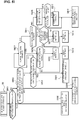
onboard sensor 1, a mapdata storage unit 2, anexternal data communicator 3, an autonomousdriving control unit 4, anactuator 5, and a display device 6. - The
onboard sensor 1 has a camera 11, aradar 12, aGPS 13, and an onboard data communicator 14. Sensor information acquired by theonboard sensor 1 is outputted to the autonomousdriving control unit 4. - The camera 11 is a surroundings recognition sensor that carries out a function of acquiring host vehicle surroundings information such as lanes, preceding vehicles, and pedestrians from image data, as a function needed for autonomous driving. The camera 11 is configured by combining, for example, a host vehicle forward recognition camera, a rearward recognition camera, a rightward recognition camera, a leftward recognition camera, etc.
- Objects on the host vehicle travel roadway, lanes, objects outside of the host vehicle travel roadway (road structures, preceding vehicles, succeeding vehicles, oncoming vehicles, surrounding vehicles, pedestrians, bicycles, motorcycles), the host vehicle travel roadway (white road lines, road borders, stop lines, crosswalks), road signs (speed limits), etc., are sensed by the camera 11.
- The
radar 12 is a distance measurement sensor that carries out a function of sensing the presence of objects in the surroundings of the host vehicle and the function of sensing distances to objects in the surroundings of the host vehicle, as functions needed for autonomous driving. "Radar 12" in this example is a general term including radar using radio waves, lidar using light, and sonar using ultrasonic waves. For example, laser radar, milliwave radar, ultrasonic radar, a laser range finder, etc., can be used as theradar 12. Theradar 12 is configured by combining, for example, host vehicle forward radar, rearward radar, rightward radar, leftward radar, etc. - Positions of objects on the host vehicle travel roadway, objects outside of the host vehicle travel roadway (road structures, preceding vehicles, succeeding vehicles, oncoming vehicles, surrounding vehicles, pedestrians, bicycles, motorcycles), etc., are sensed and distances to the objects are sensed by the
radar 12. If a viewing angle is insufficient, viewing angle may be added as appropriate. - The GPS 13 is a host vehicle position sensor that has a
GNSS antenna 13a and uses satellite communication to sense the host vehicle position (latitude and longitude) while the host vehicle is stopped or traveling. "GNSS" is an abbreviation of "Global Navigation Satellite System," and "GPS" is an abbreviation of "Global Positioning System." - The onboard data communicator 14 is an external data sensor that wirelessly communicates with the
external data communicator 3 viatransceiver antennas - In cases where the
external data communicator 3 is, for example, a data communicator mounted in another vehicle traveling in the vicinity of the host vehicle, vehicle-to-vehicle communication is performed between the host vehicle and the other vehicle. Information necessary to the host vehicle can be acquired, by request from the onboard data communicator 14, from among a variety of information retained in the other vehicle, the acquisition being made via the vehicle-to-vehicle communication. - In cases where the
external data communicator 3 is, for example, a data communicator provided to infrastructure equipment, vehicle-to-infrastructure communication is performed between the host vehicle and the infrastructure equipment. Information necessary to the host vehicle can be acquired, by request from the onboard data communicator 14, from among a variety of information retained in the infrastructure equipment, the acquisition being made via the vehicle-to-infrastructure communication. In cases where the held information has, e.g., information that map data saved in the mapdata storage unit 2 lacks, or information changed from that in the map data, it is possible for the lacking information/changed information to be supplementarily provided. In addition, it is possible to acquire traffic information, such as congestion information or travel restriction information, pertaining to a target travel route on which the host vehicle is planned to travel. - The map
data storage unit 2 is configured from an onboard memory that contains "electronic map data," in which map information and latitude/longitude are associated. The map data contained in the mapdata storage unit 2 is high-precision map data having a level of precision such that it is possible at least to recognize lanes on a road having a plurality of lanes. Using the high-precision map data makes it possible to draw a target travel route with regard for which lane the host vehicle is traveling in from among the plurality of lanes during autonomous driving. When the host vehicle position sensed by theGPS 13 is recognized as host vehicle position information by the autonomousdriving control unit 4, the mapdata storage unit 2 sends high-precision map data centered on the host vehicle position to the autonomousdriving control unit 4. - The high-precision map data has road information associated with each location, the road information being defined by nodes and links that connect the nodes. The road information includes: information that specifies the road according to the position/area of the road; and information pertaining to road classification for each road, a road width for each road, and a road shape. The road information is stored, for each item of discrimination information pertaining to the road links, in association with other information relating to roads, such as a classification of a road, a width of the road, a shape of the road, the possibility of advancing straight forward, a priority relationship pertaining to advancement, the possibility of passing other vehicles (possibility of entering an adjacent lane), a speed limit, and road signs.
- The autonomous
driving control unit 4 has a function for integrated processing of input information from theonboard sensor 1 or the mapdata storage unit 2 to generate a target travel route, a target speed profile (including an acceleration profile and/or a deceleration profile), etc. Specifically, a travel-lane-level-dependent target travel route from a current location to a destination is generated on the basis of, inter alia, the high-precision map data from the mapdata storage unit 2 or a prescribed route search technique, and, inter alia, a target speed profile aligned with the target travel route is generated. Furthermore, when it has been assessed, due to sensing results pertaining to the host vehicle surroundings as acquired by theonboard sensor 1 during stopping/traveling of the host vehicle that aligns with the target travel route, that autonomous driving cannot be maintained, the target travel route, the target speed profile, etc., are successively corrected on the basis of the sensing results pertaining to the host vehicle surroundings. - The autonomous driving control unit 4: computes, upon generation of the target travel route, a drive command value/braking command value/steering command value so that the host vehicle travels along the target travel route; outputs the computed command values to respective actuators; and causes the host vehicle to travel/stop along the target travel route. Specifically, a result from computing of the drive command value is outputted to a
drive actuator 51, a result from computing of the braking command value is outputted to abraking actuator 52, and a result from computing of the steering command value is outputted to asteering angle actuator 53. - The
actuator 5 is a control actuator for causing the host vehicle to travel/stop along the target travel route. Theactuator 5 has thedrive actuator 51, thebraking actuator 52, and thesteering angle actuator 53. - The
drive actuator 51 is an actuator that receives input of a drive command value from the autonomousdriving control unit 4 and controls drive force outputted to drive wheels. As thedrive actuator 51, for example, an engine is used in the case of an engine vehicle, an engine and a motor/generator (drive force) are used in the case of a hybrid vehicle, and a motor/generator (drive force) is used in the case of an electric automobile. - The
braking actuator 52 is an actuator that receives input of a braking command value from the autonomousdriving control unit 4 and controls braking force outputted to the drive wheels. For example, a hydraulic booster, an electric booster, a brake fluid pressure actuator, a brake motor actuator, a motor/generator (regenerative), etc., is used as thebraking actuator 52. - The
steering angle actuator 53 is an actuator that receives input of a steering angle command value from the autonomousdriving control unit 4 and controls the steering angle of steered wheels. A turning motor, etc., provided to a steering force transmission system of a steering system is used as thesteering angle actuator 53. - The display device 6 is a device that displays a screen image pertaining to, inter alia, where on a map the host vehicle is moving during stopping/traveling caused by the autonomous driving, and provides visual information pertaining to the host vehicle position to a driver and/or a passenger. The display device 6 receives input of the target travel route information, the host vehicle position information, the destination information, etc., generated by the autonomous
driving control unit 4, and displays a map, a road, the target travel route (travel route of the host vehicle), the host vehicle position, the destination, etc., on a display screen image in a readily visible manner. - The autonomous
driving control unit 4 of the autonomous driving system A is provided with a lane change controller 40 (controller) that performs a lane change control on the basis of prescribed control rules when the host vehicle traveling in the host vehicle lane makes a lane change to an adjacent lane in which another vehicle in the surroundings of the host vehicle is traveling. -
Figure 2 shows thelane change controller 40 provided to the autonomousdriving control unit 4. A control block configuration of thelane change controller 40 is described below on the basis ofFig. 2 . - The
lane change controller 40 is provided with a lane changerequest detection unit 40a, a lane changeintent detection unit 40b, a lane-change-target-setting unit 40c, a lane changeoperation determination unit 40d, a lanechange control unit 40e, and adiscriminator 40f. - The lane change
request detection unit 40a detects whether there is a request from the host vehicle to make a lane change to an adjacent lane. The detection of the request from the host vehicle to make a lane change to an adjacent lane is performed using detection methods such as those described in (a) and (b) below. - (a) It is detected that driving intervention information pertaining to manual intervention by the driver in driving of the vehicle has been produced, and that a lane change by the host vehicle to an adjacent lane has been made (driver request). For example, [this scenario] is detected according to turn signal illumination and/or an illumination manipulation. Other manipulations for steering to an adjacent lane made by the driver are also detected.
- (b) It is detected that a lane change command has been outputted by the autonomous driving control unit 4 (system request). For example, a flag signal outputted when an assessment pertaining to a lane change is made may be detected, and a configuration may be adopted in which a lane change to an adjacent lane according to a target travel route calculated by the autonomous
driving control unit 4 is detected. - In cases where it has been detected that there is a request from the host vehicle to make a lane change, the lane change
intent detection unit 40b detects whether there is any intent for another vehicle traveling in an adjacent lane to make a lane change heading toward the host vehicle lane. - A lane-change-intending other vehicle is detected using detection methods such as those described in (a) to (d) below.
- (a) The other vehicle is detected due to having illuminated a turn signal.
- (b) Behavior in which the other vehicle heads toward the host vehicle lane is detected, and the fact that preparation for a lane change has started is detected.
- (c) The other vehicle is detected in cases where the other vehicle accelerates toward a headway space of a vehicle during travel in the host vehicle lane.
- (d) Information that the other vehicle plans to execute a lane change is inputted via vehicle-to-vehicle communication between the host vehicle and the other vehicle, whereby the other vehicle is detected. Vehicles that perform vehicle-to-vehicle communication are limited to vehicles, from among a plurality of vehicles traveling in adjacent lanes, for which the arrival time at another vehicle position is earlier than a dead point arrival prediction time at which the host vehicle will arrive at a dead point. The "dead point" is an endpoint at which the host vehicle will become unable to complete a lane change to an adjacent lane when making the lane change, the dead point being present in front of the host vehicle.
- In cases where it has been detected that there is an intent for another vehicle to make a lane change heading toward the host vehicle lane, the lane-change-target-setting unit 40c establishes the lane-change-intending other vehicle as a vehicle designated for a place-swapping lane change, and sets a vacant area created due to the lane change by the designated vehicle as a target for a lane change made by the host vehicle. In this instance, the relative position of the designated vehicle relative to the host vehicle is detected, and the relative position of the designated vehicle relative to the host vehicle is established as the position of a vacant area and is set as the target for a lane change made by the host vehicle.
- Before the designated vehicle makes a lane change, the "position of the vacant area" refers to a current position of the designated vehicle, such that the vacant area will be created due to the designated vehicle making a lane change. After the designated vehicle has made a lane change, the "position of the vacant area" refers to the position where the vacant area is created due to the designated vehicle leaving the adjacent lane.
- Thus, as pertains to the "position of the vacant area," before a lane change is started and while the host vehicle and the designated vehicle are running in parallel in respective lanes, the relative position of the designated vehicle relative to the host vehicle is detected, the relative position where the designated vehicle is present relative to the host vehicle is established as a vacant area, and the vacant area is set as the target for a lane change made by the host vehicle. Specifically, the "position of the vacant area" includes the current position of the designated vehicle relative to the host vehicle, this current position actually not being a vacant area, and therefore what is detected is not a vacant space but rather the relative position of the designated vehicle relative to the host vehicle.
- In cases where only one lane-change-intending other vehicle is present, the one other vehicle is established as the vehicle designated for the place-swapping lane change. However, in cases where a plurality of lane-change-intending other vehicles are present, another vehicle having the lowest lane change risk value from among the plurality of other vehicles is established as the vehicle designated for the place-swapping lane change.
- In cases where the target for a lane change made by the host vehicle is set, the lane change
operation determination unit 40d determines an interoperation pertaining to the lane change involving a swapping of places by the host vehicle and the designated vehicle. Basically, the lane change involving a swapping of places by the host vehicle and the designated vehicle is categorized into [one of] the pre-patterned interoperation patterns (A) to (F) described below. One pattern from among the interoperation patterns (A) to (F), which are categorized in accordance with a variety of assessment conditions, is selected, and the interoperation pattern of the lane change involving a swapping of places by the host vehicle and the designated vehicle is determined. - The interoperation patterns (A) to (F) are as shown in
Fig. 3 . InFig. 3 , V1 represents the host vehicle, and V2 represents the designated vehicle. - (A) The host vehicle V1 is forward from the designated vehicle V2 and starts a lane change in advance of the designated vehicle V2.
- (B) The host vehicle V1 is forward from the designated vehicle V2 and starts a lane change at the same time as the designated vehicle V2.
- (C) The host vehicle V1 is forward from the designated vehicle V2 and starts a lane change after the designated vehicle V2.
- (D) The host vehicle V1 is rearward from the designated vehicle V2 and starts a lane change in advance of the designated vehicle V2.
- (E) The host vehicle V1 is rearward from the designated vehicle V2 and starts a lane change at the same time as the designated vehicle V2.
- (F) The host vehicle V1 is rearward from the designated vehicle V2 and starts a lane change after the designated vehicle V2.
- When the interoperation of the lane change involving a swapping of places by the host vehicle and the designated vehicle is determined by the lane change
operation determination unit 40d, the lanechange control unit 40e controls a lane change operation of the host vehicle so as to achieve the determined place-swapping lane change. - When the host vehicle has undergone the lane change involving a swapping of places by the host vehicle and the designated vehicle, the
discriminator 40f stores and saves a result from categorizing a surrounding environment that includes the host vehicle and the designated vehicle for each selected interoperation pattern (A) to (F). - In cases where the target lane change to be made by the host vehicle V1 is set, when an assessment is made by the lane change
operation determination unit 40d that the surrounding environment at the time of such setting conforms to any of the categorization results obtained by learning, an interoperation pattern in the instance of the assessed categorization result is read out from thediscriminator 40f and selected. -
Figure 4 shows an overall flow of a lane change control process executed by thelane change controller 40 provided to the autonomousdriving control unit 4. The steps inFig. 4 are described below. - In step S1, in continuation from the start of the process, an assessment is made as to whether there is a request from the host vehicle to make a lane change from a host vehicle lane to an adjacent lane. When the assessment is YES (there is a request from the host vehicle to make a lane change), the process advances to step S2; when the assessment is NO (there is no request from the host vehicle to make a lane change), the process ends.
- In step S2, in continuation from the assessment in step S1 that there is a request from the host vehicle to make a lane change, an assessment is made as to whether a lane-change-intending other vehicle is present among (one or a plurality of) vehicles in the surroundings of the host vehicle, the vehicles traveling in an adjacent lane. When the assessment is YES (a lane-change-intending other vehicle is present), the process advances to step S3; when the assessment is NO (no lane-change-intending other vehicle is present), the process ends.
- In step S3, in continuation from the assessment in step S2 that a lane-change-intending other vehicle is present, an assessment is made as to whether there is one lane-change-intending other vehicle. When the assessment is YES (there is one other vehicle), the process advances to step S6, when the assessment is NO (there are a plurality of other vehicles), the process advances to step S4.
- In step S4, in continuation from the assessment in step S3 that there are a plurality of lane-change-intending other vehicles, lane change risk values are calculated for each of the plurality of other vehicles, and the process advances to step S5.
- The lane change risk values R are calculated as follows:

- The function expression for the lane change risk values R is based on numerous experimental results, and is such that the lane change risk values R are set to a lower value commensurately with a higher headway distance, the lane change risk values R are set to a lower value commensurately with a lower speed, and the lane change risks R are set to a lower value commensurately with a lower number of traveling vehicles.
- In step S5, in continuation from the calculation in step S3 of the lane change risk value, the other vehicle having the lowest risk value among the lane change risk values of the plurality of lane-change-intending other vehicles is selected, and the process advances to step S6.
- In step S6, in continuation from the assessment in step S3 that there is one other vehicle or the selection in step S5 of the other vehicle having the lowest rick value, the one other vehicle or the other vehicle having the lowest risk value is determined to be the designated vehicle in the place-swapping lane change, and the process advances to step S7.
- In step S7, in continuation from the determination in step S6 as to the designated vehicle in the place-swapping lane change, the position (relative position) of a vacant area in the adjacent lane that will be created due to a lane change by the designated vehicle is set as the target for a lane change made by the host vehicle, and the process advances to step S8.
- Because the "target for a lane change" is the position (relative position) of a vacant area in the adjacent lane that will be created due to a lane change by the traveling designated vehicle, there is no fixed target position; rather, the "target for a lane change" is a variable target position for which the relative positional relationship with respect to the host vehicle moves as time elapses in association with the lane change operation of the designated vehicle.
- In step S8, in continuation from the setting in step S7 of the target for a lane change made by the host vehicle, a lane change operation of the host vehicle and the designated vehicle is determined in accordance with the flow chart shown in
Fig. 5 , and the process advances to step S9. - In step S9, in continuation from the determination in step S8 of the lane change operation or the assessment in step S10 that a lane change is not yet complete, a lane change control is executed according to the determined lane change operation, and the process advances to step S10.
- In step S10, in continuation from the execution in step S9 of the lane change control, an assessment is made as to whether the lane change involving a swapping of places by the host vehicle and the designated vehicle has been completed. When the assessment is YES (lane change is complete), the process ends; when the assessment is NO (lane change is not yet complete), the process returns to step S9.
-
Figure 5 shows a flow of a lane change operation determination process executed in the lane change operation determination step S8 of the lane change control process. The steps inFig. 5 are described below. - In step S801, in continuation from the start of the lane change operation determination process, a dead point arrival prediction time required for the host vehicle to arrive at a dead point is calculated, and an assessment is made as to whether the dead point arrival prediction time is less than or equal to a threshold value. When the assessment is YES (dead point arrival prediction time is less than or equal to the threshold value), the process advances to step S802; when the assessment is NO (dead point arrival prediction time is greater than the threshold value), the process advances to step S803.
- As pertains to the "dead point," for example, in the case of a road that merges in an X shape, the "D.P" shown in
Fig. 6 is a dead point. In the case of a road that branches in a Y shape, the branch point at which the road is divided into two roadways serves as a dead point. - The "dead point arrival prediction time" is calculated according to the speed of the host vehicle, the host vehicle position, and a distance remaining to the dead point. In cases where the host vehicle is traveling on a road in which a plurality of lanes extending parallel to each other are present, there is no dead point, and the dead point arrival prediction time is infinite.
- When any of the interoperation patterns (A) to (F) has been selected, the "threshold value" is set to a value derived from a minimum required time for the place-swapping lane change operation to be made according to the selected pattern. Specifically, the assessment that the dead point arrival prediction time is less than or equal to the threshold value refers to a situation in which any of the interoperation patterns (A) to (F) has been selected and there is no temporal margin for making the place-swapping lane change according to the selected pattern.
- In step S802, in continuation from the assessment in step S801 that the dead point arrival prediction time is less than or equal to the threshold value, a lane change by the host vehicle is started immediately instead of a pattern operation, without selecting any of the interoperation patterns (A) to (F).
- In step S803, in continuation from the assessment in step S801 that the dead point arrival prediction time is greater than the threshold value, an assessment is made as to whether it is the case that no objects (traveling vehicles, stopped vehicles, etc.) are present in front of or behind the host vehicle or the designated vehicle. When the assessment is YES (no objects are present in front or behind), the process advances to step S804; when the assessment is NO (an object is present in front or behind), the process advances to step S805.
- In step S804, in continuation from the assessment in step S803 that no objects are present in front or behind, a change in speed from the current speed of the host vehicle when the place-swapping lane change is made is calculated for each of the patterns (A) to (F), and the interoperation pattern for which the change in speed is smallest is selected.
- In step S805, in continuation from the assessment in step S803 that an object is present in front or behind, an assessment is made as to whether the surrounding environment, which is formed by vehicles traveling in the host vehicle lane and vehicles traveling in the adjacent lane, conforms to any learned categorization result. When the assessment is YES (the surrounding environment conforms to a categorization result), the process advances to step S806; when the assessment is NO (the surrounding environment does not conform to a categorization result), the process advances to step S807.
- The "learned categorization result" is a categorization result that is stored and saved by the
discriminator 40f each time the host vehicle undergoes the lane change involving a swapping of places by the host vehicle and the designated vehicle, the categorization result pertaining to a surrounding environment that includes the host vehicle and the designated vehicle. - In step S806, in continuation from the assessment in step S805 that the surrounding environment conforms to a categorization result, the pattern that corresponds to the assessed categorization result is selected.
- The pattern that corresponds to the assessed categorization result is selected according to reading from the
discriminator 40f, in which the result from categorizing the surrounding environment is stored and saved together with one selected pattern from among the interoperation patterns (A) to (F). - In step S807, in continuation from the assessment in step S805 that the surrounding environment does not conform to a categorization result, an assessment is made as to whether the adjacent lane is more crowded than the host vehicle lane. When the assessment is YES (the adjacent lane is more crowded), the process advances to step S808; when the assessment is NO (the adjacent lane is not more crowded), the process advances to step S811.
- The extent of crowding of the host vehicle lane and the adjacent lane is set according to a range in which a crowding identification section can be sensed by the
onboard sensor 1, the crowding identification section including the host vehicle and the designated vehicle, and being of the same distance as a distance that can be subject to the place-swapping lane change by the host vehicle. The degree of crowding of the host vehicle lane is calculated according to the number of vehicles present in the crowding identification section in the host vehicle lane, and the degree of crowding of the adjacent lane is calculated according to the number of vehicles present in the crowding identification section in the adjacent lane. When the difference between the degree of crowding in the adjacent lane and the degree of crowding in the host vehicle lane is greater than or equal to a threshold value, it is assessed that the adjacent lane is more crowded. - In step S808, in continuation from the assessment in step S807 that the adjacent lane is more crowded, an assessment is made as to whether the host vehicle is forward from the designated vehicle. When the assessment is YES (the host vehicle is forward from the designated vehicle), the process advances to step S809; when the assessment is NO (the host vehicle is rearward from the designated vehicle), the process advances to step S810.
- In step S809, in continuation from the assessment in step S808 that the host vehicle is forward from the designated vehicle, the interoperation pattern (C) is selected from among the interoperation patterns (A) to (F) shown in
Fig. 3 . - In step S810, in continuation form the assessment in step S808 that the host vehicle is rearward from the designated vehicle, the interoperation pattern (F) is selected from among the interoperation patterns (A) to (F) shown in
Fig. 3 . - In step S811, in continuation from the assessment in step S807 that the adjacent lane is not more crowded, an assessment is made as to whether the host vehicle lane is more crowded than the adjacent lane. When the assessment is YES (the host vehicle lane is more crowded), the process advances to step S812; when the assessment is NO (the host vehicle lane is not more crowded), the process advances to step S815.
- When the difference between the degree of crowding in the host vehicle lane and the degree of crowding in the adjacent lane is greater than or equal to a threshold value, it is assessed that the host vehicle lane is more crowded.
- In step S812, in continuation from the assessment in step S811 that the host vehicle lane is more crowded, an assessment is made as to whether the host vehicle is forward from the designated vehicle. When the assessment is YES (the host vehicle is forward from the designated vehicle), the process advances to step S813; when the assessment is NO (the host vehicle is rearward from the designated vehicle), the process advances to step S814.
- In step S813, in continuation from the assessment in step S812 that the host vehicle is forward from the designated vehicle, the interoperation pattern (A) is selected from among the interoperation patterns (A) to (F) shown in
Fig. 3 . - In step S814, in continuation from the assessment in step S812 that the host vehicle is rearward from the designated vehicle, the interoperation pattern (D) is selected from among the interoperation patterns (A) to (F) shown in
Fig. 3 . - In step S815, in continuation from the assessment in step S811 that the host vehicle lane is not more crowded, lane change risk values are calculated for each of the interoperation patterns (A) to (F) shown in
Fig. 3 , and the process advances to step S816. - The lane change risk values R are calculated using the following formula, as described in regard to step S4:

- In step S816, in continuation from the calculation in step S815 of the lane change risk values, the smallest value is selected from among the lane change risk values for each of the interoperation patterns (A) to (F), and an assessment is made as to whether the selected smallest risk value is greater than or equal to a threshold value. When the assessment is YES (the risk value is greater than or equal to the threshold value), the process advances to step S817; when the assessment is NO (the risk value is less than the threshold value), the process advances to step S818.
- Situations when the pattern (B) or (E) has been selected as the interoperation pattern for which the lane change risk value R is smallest are excluded from the assessment as to whether the risk value is greater than or equal to the threshold value. Specifically, when any of the patterns (A), (C), (D), and (F), in which times at which the host vehicle and the designated vehicle start a lane change are made to differ from each other, has been selected, an assessment is made as to whether the risk value is greater than or equal to the threshold value.
- In step S817, in continuation from the assessment in step S816 that the risk value is greater than or equal to the threshold value, a time difference between the time at which the designated vehicle starts a lane change and the time at which the host vehicle starts a lane change is corrected from a preset reference time, and the process advances to step S818.
- In the "correction of the time difference," in cases where the lane change risk value R is greater than or equal to the threshold value, the time difference between the time at which the designated vehicle starts a lane change and the time at which the host vehicle starts a lane change is set to a lower time difference commensurately with a higher magnitude of the lane change risk value R.
- In step S818, in continuation from the assessment in step S816 that the risk value is less than or equal to the threshold value or the correction in step S817 of the time difference, the interoperation pattern for which the lane change risk value R is smallest is selected from among the interoperation patterns (A) to (F).
- The action in the first embodiment is described next in each of "Lane Change Control Action," "Lane-Change-Target-Setting Action," and "Lane Change Operation Determination Action." Below, the host vehicle lane is established as L1, the host vehicle is established as V1, the adjacent lane is established as L2, the designated vehicle is established as V2, another vehicle in the host vehicle lane is established as V3, another vehicle in the adjacent lane is established as V4, and the dead point is established as D.P.
- In the device disclosed in
patent document 1, in cases where a host vehicle performs a lane change, it is expected that other vehicles will decelerate or perform lane changes to lanes other than the host vehicle travel lane, and surrounding spaces between other vehicles are sensed. However,patent document 1 does not disclose a method in which the host vehicle is caused to make a lane change to an adjacent lane when the sensed surrounding spaces between other vehicles are not sufficient. Therefore, in a scenario in which the host vehicle is to make a lane change to an adjacent lane in a road having an X-shaped merge, or a plurality of lanes, the host vehicle will be unable to make the lane change in cases where there is not a sufficient area of space before the lane change. - For example, in the device disclosed in
patent document 1, when the host vehicle is to make a lane change to an adjacent lane due to a driver request or a system request, it is impossible to perform the lane change when it is impossible to ensure a space in the adjacent lane for the host vehicle to cut into through a lane change. For example, when a plurality of other vehicles are traveling at substantially equal intervals in an adjacent lane adjacent to the host vehicle on a road having an X-shaped merge section, as shown inFig. 6 , sufficient space for the host vehicle to cut into the adjacent lane through a lane change cannot be ensured, and it is impossible to perform the lane change. In addition, when the host vehicle stops in order to perform a lane change and waits until a sufficient space for cutting in can be ensured, the host vehicle becomes an obstacle to succeeding vehicles that travel in the host vehicle lane, thereby causing congestion. - The present invention was contrived in view of the problem described above. In the present invention, whether there is a request from the host vehicle V1 to make a lane change to the adjacent lane L2 is detected, and in cases where it has been detected that there is a request from the host vehicle V1 to make a lane change, whether there is any intent for the other vehicle V4 traveling in the adjacent lane L2 to make a lane change heading toward the host vehicle lane L1 is detected. In cases where it has been detected that there is an intent for the other vehicle V4 to make a lane change heading toward the host vehicle lane L1, the lane-change-intending other vehicle V4 is established as a vehicle V2 designated for a place-swapping lane change. A lane change control method is employed in which the position (relative position) of a vacant area that will be created due to the lane change by the designated vehicle V2 is set as a target lane change to be made by the host vehicle V1.
- Specifically, when it is assessed that there is no request from the host vehicle V1 to make a lane change, the process in the flow chart shown in
Fig. 4 advances from S1 to the end. When it is assessed that there is a request from the host vehicle V1 to make a lane change but there is no lane-change-intending other vehicle V4, the process in the flow chart shown inFig. 4 advances from S1 through S2 to the end. In both of these cases, for example, a command to continue the autonomous driving control without modification and to carry out autonomous driving travel is outputted in the host vehicle V1, without performance of a place-swapping lane change. - However, when it has been assessed that there is a request from the host vehicle V1 to make a lane change and there is a lane-change-intending vehicle V4, the process in the flow chart shown in
Fig. 4 advances from S1 through S2, S3, (S4, S5), S6, S7, S8, and S9 to S10. A vehicle V2 designated for the place-swapping lane change is determined in S6, a target lane change to be made by the host vehicle V1 is set in S7, the lane change operation of the host vehicle V1 and the designated vehicle V2 is determined in S8, and the lane change control is executed in S9. The flow advancing from S9 to S10 is repeated until the lane change control is complete. When the lane change control is complete, the process advances from S10 to the end. - For example, an action for a lane change involving a swapping of places by the host vehicle V1 and the designated vehicle V2 on a road having an X-shaped merge location is described on the basis of
Fig. 6 . When the host vehicle V1 requests a lane change at a position immediately in front of the X-shaped merge location, another vehicle V4 having a turn signal illuminated is present in the adjacent lane L2 at the same timing. In this case, the other vehicle V4 having the turn signal illuminated is recognized as a lane-change-intending vehicle, and this other vehicle V4 is determined to be the vehicle V2 designated for the place-swapping lane change. The designated vehicle V2 is to make a lane change to the host vehicle lane L1, as shown by an arrow extending from the designated vehicle V2 inFig. 6 . In this instance, the host vehicle V1 establishes the position of a vacant area that will be created due to a lane change by the designated vehicle V2 (relative position of a vacant area that moves between the other vehicle V4-2 and the other vehicle V4-3 due to travel), within the adjacent lane L2, as a target for a lane change, and makes a lane change to the adjacent lane L2, as shown by an arrow extending from the host vehicle V1 inFig. 6 . Thus, the lane-change-intending other vehicle is established as the vehicle V2 designated for the place-swapping lane change, and the position (relative position) of the vacant area that will be created due to the lane change by the designated vehicle V2 is set as the target lane change to be made by the host vehicle V1. - As a result, a configuration is adopted in which, in a scenario in which the host vehicle V1 requests a lane change to the adjacent lane L2, it is possible to make the lane change to the position of the designated vehicle V2, which makes a lane change to the host vehicle lane L1, even in situations where there is not a sufficient area of space before the lane change made by the host vehicle V1. Thus, in situations where a plurality of other vehicles V4 are traveling at substantially equal intervals in the adjacent lane L2 for which a lane change was requested by the host vehicle V1 on a road having an X-shaped merge, as shown in
Fig. 6 , for example, sufficient space for the host vehicle V1 to cut into the adjacent lane L2 through a lane change cannot be ensured. However, even in situations where space for the host vehicle V1 to cut into the adjacent lane L2 cannot be ensured, it is possible for the host vehicle V1 and the designated vehicle V2 to make a lane change by a swapping of places. In addition, situations where the host vehicle V1 stops in order to make a lane change and waits until a sufficient space for cutting into the adjacent lane L2 can be ensured are eliminated. Therefore, it is possible to prevent the host vehicle V1 from becoming an obstacle to succeeding vehicles that travel in the host vehicle lane and causing congestion, and the lane change does not serve as a factor in obstructing traffic flows. In addition, it is possible to suppress fuel consumption of the host vehicle V1. Furthermore, it is also possible to reduce stress imparted to a passenger in the host vehicle V1. - An action for determining the vehicle V2 designated for the place-swapping lane change on a road having an X-shaped merge location, and an action for setting the target lane change to be made by the host vehicle V1, are described on the basis of
Figs. 7 and 8 . - When there is a request from the host vehicle V1 to make a lane change and there is one lane-change-intending other vehicle V4, the process in the flow chart shown in
Fig. 4 advances from S1 through S2, S3, and S6 to S7. The one other vehicle V4 is determined as a vehicle V2 designated for the place-swapping lane change in S6. The position (relative position) of a vacant area in the adjacent lane L2 that will be created due to a lane change by the designated vehicle V2 is set as the target lane change to be made by the host vehicle V1 in S7. - Specifically, when there is a request from the host vehicle V1 to make a lane change, and three other vehicles V4-1, V4-2, V4-3 and one vehicle-of-interest candidate for which a turn signal is illuminated are traveling in the adjacent lane as shown in
Fig. 7 , the one vehicle-of-interest candidate is determined as the designated vehicle V2. The position (relative position) of a vacant area that will be created due to a lane change by the designated vehicle V2 and will be formed between the other vehicle V4-2 and the other vehicle V4-3 in the adjacent lane L2 is set as the target lane change to be made by the host vehicle V1. - When there is a request from the host vehicle V1 to make a lane change and there are a plurality of lane-change-intending other vehicles V4, the process in the flow chart shown in
Fig. 4 advances from S1 through S2, S3, S4, S5, and S6 to S7. The lane change risk values R for each of the plurality of other vehicles V4 are calculated in S4. The other vehicle having the lowest risk value among the lane change risk values of the plurality of lane-change-intending other vehicles is selected as a vehicle-of-interest candidate in S5. The vehicle-of-interest candidate having the lowest lane change risk value R is determined as the vehicle V2 designated for the place-swapping lane change in S6. - Specifically, when there is a request from the host vehicle V1 to make a lane change, and two other vehicles V4-1, V4-2 and three vehicle-of-interest candidates V2-1, V2-2, V2-3 for which a turn signal is illuminated are traveling in the adjacent lane (*4) as shown in
Fig. 8 , the vehicle-of-interest candidate V2-2 having the lowest lane change risk value R is determined as the designated vehicle V2. The position (relative position) of a vacant area that will be created due to a lane change by the designated vehicle V2 and will be formed between the other vehicle V4-2 and the vehicle-of-interest candidate V2-3 in the adjacent lane L2 is set as the target lane change to be made by the host vehicle V1. - Thus, when there are a plurality of lane-change-intending other vehicles V4, the vehicle-of-interest candidate V2-2 having the lowest lane change risk value R is determined as the designated vehicle V2. Therefore, in a scenario in which a lane change involving a swapping of places by the host vehicle V1 and the designated vehicle V2 is performed, it is possible to smoothly perform the place-swapping lane change with sufficient spatial and temporal margins.
- In cases where the dead point arrival prediction time is less than or equal to the threshold value, the process in the flow chart shown in
Fig. 5 advances from S801 to S802. In S802, the lane change by the host vehicle V1 is started immediately without selecting any of the interoperation patterns (A) to (F). - Specifically, when the pattern for making a lane change involving a swapping of places by the host vehicle V1 and the designated vehicle V2 is stipulated in each of the interoperation patterns (A) to (F), if the dead point arrival prediction time is less than or equal to the threshold value, the lane change by the host vehicle V1 must be abandoned. Specifically, any of the interoperation patterns (A) to (F) is selected, and there is no temporal margin for making the place-swapping lane change according to the selected pattern.
- However, in cases of, for example, a road that merges in an X shape, starting the lane change by the host vehicle V1 immediately when it has been assessed that the dead point arrival prediction time is less than or equal to the threshold value makes it possible to perform a lane change involving a swapping of places by the host vehicle V1 and the designated vehicle V2. As a result, in a scenario in which the dead point arrival prediction time is less than or equal to the threshold value, it is possible to perform a lane change by the host vehicle V1 by handling this scenario as an exception to the stipulation of interoperation patterns between the host vehicle V1 and the designated vehicle V2 in each of the patterns (A) to (F).
- In cases where the dead point arrival prediction time is greater than the threshold value, but there are no objects present in front of or behind the host vehicle V1 or the designated vehicle V2, the process in the flow chart shown in
Fig. 5 advances from S801 through S803 to S804. In S804, the change in speed from the current speed of the host vehicle V1 when the place-swapping lane change is performed is calculated for each of the patterns (A) to (F), and the interoperation pattern for which the change in speed is smallest is selected. - Specifically, when the pattern for making a lane change involving a swapping of places by the host vehicle V1 and the designated vehicle V2 is stipulated in each of the interoperation patterns (A) to (F), in cases where there are no objects in front of or behind the host vehicle V1 or the designated vehicle V2, any of the patterns (A) to (F) can be selected. However, when a pattern is appropriately selected, it is necessary to cause the speed of the host vehicle V1 to transition from a deceleration to acceleration, or to transition from acceleration to deceleration.
- However, in cases where no objects are present in front of or behind the host vehicle V1 or the designated vehicle V2, selecting the interoperation pattern for which the change in speed is smallest minimizes the change in speed of the host vehicle V1 in the place-swapping lane change. As a result, in a scenario in which no objects are present in front of or behind the host vehicle V1 or the designated vehicle V2, it is possible to minimize the change in speed of the host vehicle V1 in the place-swapping lane change when the interoperation pattern of the host vehicle V1 and the designated vehicle V2 is stipulated in each of the patterns (A) to (F).
- In cases where the dead point arrival prediction time is greater than the threshold value and an object is present in front of or behind the host vehicle V1 or the designated vehicle V2, but the surrounding environment conforms to any learned categorization result, the process in the flow chart shown in
Fig. 5 advances from S801 through S803 and S805 to S806. In S806, the pattern corresponding to the assessed categorization result from among the interoperation patterns (A) to (F) is read out from thediscriminator 40f and is selected. - Specifically, when the pattern for making a lane change involving a swapping of places by the host vehicle V1 and the designated vehicle V2 is stipulated in each of the interoperation patterns (A) to (F), if the lane change risk values R are to be calculated for all of the patterns (A) to (F) and the pattern having the smallest risk value is to be selected, the calculation becomes troublesome.
- However, attention is drawn to the fact that stipulating the pattern in each of the interoperation patterns (A) to (F) makes it possible to use the pattern in a learning control. Specifically, the categorization results pertaining to the surrounding environment that includes the host vehicle V1 and the designated vehicle V2, and the interoperation pattern selected for each categorization result, can be stored and saved in the
discriminator 40f each time [the host vehicle V1] undergoes a lane change involving a swapping of places by the host vehicle V1 and the designated vehicle V2. As a result, in a scenario in which [the host vehicle V1] has in the past undergone the same environment as the surrounding environment that includes the host vehicle V1 and the designated vehicle V2, using the learning result in selection of the interoperation pattern for the host vehicle V1 and the designated vehicle V2 makes it possible to easily perform a process to select an operation pattern in a short period of time. - A situation is addressed in which the dead point arrival prediction time is greater than the threshold value, an object is present in front of or behind the host vehicle V1 or the designated vehicle V2, and the surrounding environment does not conform to any learned categorization result. In cases where these three conditions are fulfilled, and where the adjacent lane L2 is more crowded than the host vehicle lane L1 and the host vehicle V1 is present forward from the designated vehicle V2, the procedure in the flow chart shown in
Fig. 5 advances from S801 through S803, S805, S807, and S808 to S809. In S809, the interoperation pattern (C) is selected from among the interoperation patterns (A) to (F) shown inFig. 3 . In cases where the three conditions described above are fulfilled, and where the adjacent lane L2 is more crowded than the host vehicle lane L1 and the host vehicle V1 is present rearward from the designated vehicle V2, the procedure in the flow chart shown inFig. 5 advances from S801 through S803, S805, S807, and S808 to S810. In S810, the interoperation pattern (F) is selected from among the interoperation patterns (A) to (F) shown inFig. 3 . - Specifically, when the adjacent lane L2 is more crowded than the host vehicle lane L1, if the designated vehicle V2 first leaves the adjacent lane through a lane change, the vacant area is ensured, and the host vehicle V1 then enters the vacant area through a lane change, it is possible to smoothly perform the place-swapping lane change. Specifically, when the pattern for making a lane change involving a swapping of places by the host vehicle V1 and the designated vehicle V2 is stipulated in each of the interoperation patterns (A) to (F), the patterns (A), (B), (D), and (E) are excluded from among the patterns (A) to (F).
- However, in cases where the adjacent lane L2 is more crowded than the host vehicle lane L1 and the host vehicle V1 is present forward from the designated vehicle V2, the interoperation pattern (C) is selected. Moreover, in cases where the adjacent lane L2 is more crowded than the host vehicle lane L1 and the host vehicle V1 is present rearward from the designated vehicle V2, the interoperation pattern (F) is selected, as shown in
Fig. 9 . Therefore, due to the host vehicle V1 being positioned rearward from the designated vehicle V2 and the lane change by the host vehicle V1 being started after that of the designated vehicle V2, the designated vehicle V2 first leaves the adjacent lane through a lane change, the vacant area is ensured, and the place-swapping lane change is smoothly made. As a result, in a scenario in which the adjacent lane L2 is more crowded than the host vehicle lane L1, is it possible to smoothly perform the place-swapping lane change through selection of a suitable pattern when the interoperation pattern of the host vehicle V1 and the designated vehicle V2 is stipulated in each of the patterns (A) to (F). - A situation is addressed in which the dead point arrival prediction time is greater than the threshold value, an object is present in front of or behind the host vehicle V1 or the designated vehicle V2, and the surrounding environment does not conform to any learned categorization result. In cases where these three conditions are fulfilled, and where the host vehicle lane L1 is more crowded than the adjacent lane L2 and the host vehicle V1 is present forward from the designated vehicle V2, the process in the flow chart shown in
Fig. 5 advances from S801 through S803, S805, S807, S811, and S812 to S813. In S813, the interoperation pattern (A) is selected from among the interoperation patterns (A) to (F). In cases where the three conditions described above are fulfilled, and where the host vehicle lane L1 is more crowded than the adjacent lane L2 and the host vehicle V1 is present rearward from the designated vehicle V2, the process in the flow chart shown inFig. 5 advances from S801 through S803, S805, S807, S811, and S812 to S814. In S814, the interoperation pattern (D) is selected from among the interoperation patterns (A) to (F). - Specifically, when the host vehicle lane L1 is more crowded than the adjacent lane L2, if the host vehicle V1 first leaves the crowded host vehicle lane L1 through a lane change, and the designated vehicle V2 then ensures the vacant area of the host vehicle V1 through a lane change, it is possible to smoothly make the place-swapping lane change. Specifically, when the pattern for making a lane change involving a swapping of places by the host vehicle V1 and the designated vehicle V2 is stipulated in each of the interoperation patterns (A) to (F), the patterns (B), (C), (E), and (F) are excluded from among the patterns (A) to (F).
- However, in cases where the host vehicle lane L1 is more crowded than the adjacent lane L2 and the host vehicle V1 is present forward from the designated vehicle V2, the interoperation pattern (A) is selected. Moreover, in cases where the host vehicle lane L1 is more crowded than the adjacent lane L2 and the host vehicle V1 is present rearward from the designated vehicle V2, the interoperation pattern (D) is selected. As a result, in a scenario in which the host vehicle lane L1 is more crowded than the adjacent lane L2, is it possible to smoothly perform the place-swapping lane change through selection of a suitable pattern when the interoperation pattern of the host vehicle V1 and the designated vehicle V2 is stipulated in each of the patterns (A) to (F).
- A situation is addressed in which the dead point arrival prediction time is greater than the threshold value, an object is present in front of or behind the host vehicle V1 or the designated vehicle V2, and the surrounding environment does not conform to any learned categorization result. In cases where these three conditions are fulfilled, and where the difference between the degrees of crowding of the host vehicle lane L1 and the adjacent lane L2 is less than or equal to a threshold value, the process in the flow chart shown in
Fig. 5 advances from S801 through S803, S805, S807, S811, and S815 to S816. In S815, lane change risk values R are calculated for each of the interoperation patterns (A) to (F) shown inFig. 3 . In S816, the smallest value is selected from among the lane change risk values R for each of the interoperation patterns (A) to (F), and an assessment is made as to whether the selected smallest risk value R is greater than or equal to a threshold value. In cases where the assessment in S816 is that the lane change risk value R is less than the threshold value, the process advances from S816 to S818. In S818, the interoperation pattern for which the lane change risk value R is smallest is selected from among the interoperation patterns (A) to (F). - Specifically, when the pattern for making a lane change involving a swapping of places by the host vehicle V1 and the designated vehicle V2 is stipulated in each of the interoperation patterns (A) to (F), a variety of conditions are present as selection conditions pertaining to which pattern from among the patterns (A) to (F) is selected.
- By contrast, the lane change risk values R are calculated for each of the interoperation patterns (A) to (F), and the operation pattern having the smallest value from among the calculated lane change risk values R(A) to R(F) is selected. As a result, in a scenario in which a lane change involving a swapping of places by the host vehicle V1 and the designated vehicle V2 is made, it is possible to increase the probability of success of lane changes and to perform the place-swapping lane change when the interoperation patterns of the host vehicle V1 and the designated vehicle V2 are stipulated in each of the patterns (A) to (F).
- For example, as shown in the left-side portion of
Fig. 10 , if the interoperation pattern (D) is selected when the host vehicle V1 is present rearward from the designated vehicle V2, the headway distance La to a vehicle traveling in the host vehicle lane widens, but the headway distance Lo to a vehicle traveling in the adjacent lane narrows. As shown in the right-side portion ofFig. 10 , if the interoperation pattern (F) is selected when the host vehicle V1 is present rearward from the designated vehicle V2, the headway distance La to a vehicle traveling in the host vehicle lane narrows in comparison with a case where the interoperation pattern (D) is selected. However, the headway distance Lo to a vehicle traveling in the adjacent lane widens in comparison with a case where the interoperation pattern (D) is selected. Thus, in cases where the host vehicle V1 and the designated vehicle V2 have the relationship shown inFig. 10 , the interoperation pattern (F) is selected, the interoperation pattern (F) being such that the lane change risk value R reaches a low value due to equalization of the headway in which the length of the arrows depending on the lane change by the host vehicle V1 and the designated vehicle V2 decreases. The relationship shown is such that, if the movement distance depending on the lane change by the host vehicle V1 and the designated vehicle V2 (length of arrows inFig. 10 ) is long, the lane change risk value R increases, and if the headway is short, the lane change risk value R increases. - However, in cases where the assessment in S816 is that the lane change risk value is greater than or equal to the threshold value, the process advances from S816 through S817 to S818. In S817, a time difference between the time at which the designated vehicle V2 starts a lane change and the time at which the host vehicle V1 starts a lane change is corrected from a preset reference time. In S818, the interoperation pattern for which the lane change risk value R is smallest is selected from among the interoperation patterns (A) to (F).
- Specifically, a situation is addressed in which, when the interoperation pattern for which the lane change risk value is smallest is selected from among the interoperation patterns (A) to (F), the lane change risk value R itself is a low value, as shown in the left-side portion of
Fig. 11 . In this case, it is possible to increase the probability of success of lane changes even if the time difference between the time at which the designated vehicle V2 starts a lane change and the time at which the host vehicle V1 starts a lane change is set to the preset reference time (e.g., about 2.0 sec). - By contrast, a situation is addressed in which, when the interoperation pattern for which the lane change risk value R is smallest is selected from among the interoperation patterns (A) to (F), the lane change risk value R itself is a high value, as shown in the right-side portion of
Fig. 11 . In this case, when the time difference between the time at which the designated vehicle V2 starts a lane change and the time at which the host vehicle V1 starts a lane change is set to the preset reference time, it is impossible to increases the probability of success of lane changes. In cases where the lane change risk value is greater than or equal to the threshold value, the time difference between the time at which the designated vehicle V2 starts a lane change and the time at which the host vehicle V1 starts a lane change is corrected so as to reach a time (e.g., about 0.5 sec) that is shorter than the preset reference time. As a result, in a scenario in which the pattern for which the lane change risk value R is smallest is selected, reducing the time difference between the lane change start times when the lane change risk value is greater than or equal to the threshold value makes it possible to increase the probability of success of lane changes and to perform the place-swapping lane change. Correction of the time difference is limited to use when the pattern (A), (C), (D), or (F) is selected from among the interoperation patterns (A) to (F). - As described above, the driving assist method and the driving assist device of the first embodiment exhibit the effects listed below.
- (1) A driving assist method in which a host vehicle V1 traveling in a host vehicle lane L1 comprises a controller (the lane change controller 40) that performs a lane change control to make a lane change to an adjacent lane L2 in which another vehicle V4 present in the surroundings of the host vehicle is traveling,
wherein:- whether there is a request from the host vehicle V1 to make a lane change to the adjacent lane L2 is detected;
- in cases where it has been detected that there is a request from the host vehicle V1 to make a lane change, whether there is any intent for another vehicle V4 traveling in the adjacent lane L2 to make a lane change heading toward the host vehicle lane L1 is detected;
- in cases where it has been detected that there is an intent for the other vehicle V4 to make a lane change heading toward the host vehicle lane L1, the lane-change-intending other vehicle V4 is established as a vehicle V2 designated for a place-swapping lane change; and
- the position of a vacant area that will be created due to the lane change by the designated vehicle V2 is set as a target lane change to be made by the host vehicle V1 (
Fig. 6 ).
Thus, the lane-change-intending other vehicle V4 is established as the vehicle V2 designated for the place-swapping lane change, and the position of the vacant area that will be created due to the lane change by the designated vehicle V2 is set as the target lane change to be made by the host vehicle V1. As a result, it is possible to provide a driving assist method configured so that, in a scenario in which the host vehicle V1 requests a lane change to the adjacent lane L2, it is possible to make a lane change to the position of the designated vehicle V2, which makes a lane change to the host vehicle lane L1, even in situations where there is not a sufficient area of space before the lane change by the host vehicle V1. Specifically, it is possible to make a lane change to the vacant area that will be created due to the lane change by the designated vehicle V2 even when the vacant area for making the lane change to the adjacent lane L2 is small. - (2) The relative position of the designated vehicle V2 relative to the host vehicle V1 is detected, and
the relative position of the designated vehicle V2 relative to the host vehicle V1 is established as the position of a vacant area and is set as the target lane change to be made by the host vehicle V1 (Fig. 2 ).
Thus, the relative position of the designated vehicle V2 relative to the host vehicle V1 is detected, thereby making it possible to detect the position of a vacant area that will be created due to the lane change by the designated vehicle V2 even while the host vehicle V1 and the designated vehicle V2 are traveling. Therefore, it is possible to set the position of the vacant area that will be created due to the lane change by the designated vehicle V2 as the target for a lane change even while the host vehicle V1 and the designated vehicle V2 are traveling. - (3) In cases where a plurality of lane-change-intending other vehicles V4 are present, another vehicle V4 having the lowest lane change risk value R from among the plurality of other vehicles V4 is established as the vehicle V2 designated for a place-swapping lane change (
Fig. 8 ).
Thus, when there are a plurality of lane-change-intending other vehicles V4, the vehicle-of-interest candidate for which the lane change risk value R is smallest is set as the designated vehicle V2. As a result, in a scenario in which the lane change involving a swapping of places by the host vehicle V1 and the designated vehicle V2 is performed, it is possible to smoothly perform the place-swapping lane change with sufficient spatial and temporal margins. - (4) When the designated vehicle V2 is determined, the position of the host vehicle V1 is established as a position forward from or rearward from the designated vehicle V2, and a place-swapping lane change is started while a positional relationship has been assumed in which the host vehicle V1 and the designated vehicle V2 are offset in the front-rear direction (
Fig. 3 ).
Thus, because the possibility that the vehicles will interfere with each other is greater if the place-swapping lane change is started while the host vehicle V1 and the designated vehicle V2 are horizontally aligned, a configuration is adopted in which the place-swapping lane change is started with a positional relationship assumed in which the host vehicle V1 and the designated vehicle V2 are offset in the front-rear direction. As a result, in a scenario in which the lane change involving a swapping of places by the host vehicle V1 and the designated vehicle V2 is started, it is possible to start the place-swapping lane change in a manner in which interference between the host vehicle V1 and the designated vehicle V2 is minimized. - (5) Interoperation patterns for the lane change made by the host vehicle V1 and the designated vehicle V2 are divided into six interoperations patterns (A) to (F); and
in cases where the target lane change to be made by the host vehicle V1 is set, one pattern is selected from among the interoperation patterns (A) to (F), and a lane change operation of the host vehicle V1 is determined (Fig. 3 ).
Thus, because basic interoperations for the lane change made by the host vehicle V1 and the designated vehicle V2 are established, the interoperations are divided into the six interoperation patterns (A) to (F) beforehand. As a result, in a scenario in which the lane change involving a swapping of places by the host vehicle V1 and the designated vehicle V2 is performed, it is possible to economize a process for determining the interoperation pattern of the host vehicle V1 and the designated vehicle V2 for each scenario, and to reduce a computation processing load during travel. - (6) In cases where the adjacent lane L2 in which the designated vehicle V2 is traveling is more crowded than the host vehicle lane L1 in which the host vehicle V1 is traveling, the probability of selecting the interoperation pattern in (C) or (F) is increased (
Fig. 5 ).
Thus, if the interoperation pattern in (C) or (F), in which the designated vehicle V2 first leaves the adjacent lane L2 through a lane change and the vacant area for the host vehicle V1 is ensured, is selected when the adjacent lane L2 is more crowded, the place-swapping lane change is smoothly made. As a result, in a scenario in which the adjacent lane L2 is more crowded than the host vehicle lane L1, is it possible to smoothly perform the place-swapping lane change through selection of a suitable pattern when the interoperation pattern of the host vehicle V1 and the designated vehicle V2 is stipulated in each of the patterns (A) to (F). - (7) In cases where the host vehicle lane L1 in which the host vehicle V1 is traveling is more crowded than the adjacent lane L2 in which the designated vehicle V2 is traveling, the probability of selecting the interoperation pattern in (A) or (D) is increased (
Fig. 5 ).
Thus, if the interoperation pattern in (A) or (D), in which the host vehicle V1 first leaves the host vehicle lane L1 through a lane change and the vacant area for the designated vehicle V2 is ensured, is selected when the host vehicle lane L1 is more crowded, the place-swapping lane change is smoothly made. As a result, in a scenario in which the host vehicle lane L1 is more crowded than the adjacent lane L2, is it possible to smoothly perform the place-swapping lane change through selection of a suitable pattern when the interoperation pattern of the host vehicle V1 and the designated vehicle V2 is stipulated in each of the patterns (A) to (F). - (8) Lane change risk values R for the host vehicle V1 and the designated vehicle V2 are calculated for each of the six interoperation patterns (A) to (F); and
one interoperation pattern having the smallest value from among the lane change risk values R is selected, and the lane change operation of the host vehicle V1 is determined (Fig. 10 ).
Thus, the lane change risk values R are calculated for each of the interoperation patterns (A) to (F), and a configuration is adopted in which the interoperation pattern having the smallest value from among the calculated lane change risk values R(A) to R(F) is selected. As a result, in a scenario in which a lane change involving a swapping of places by the host vehicle V1 and the designated vehicle V2 is made, it is possible to increase the probability of success of lane changes and to perform the place-swapping lane change when the interoperation patterns of the host vehicle V1 and the designated vehicle V2 are stipulated in each of the patterns (A) to (F). - (9) In cases where a pattern in which the times at which the host vehicle V1 and the designated vehicle V2 start a lane change are caused to differ from each other is selected as the interoperation pattern, and where the lane change risk value R is greater than or equal to a threshold value, a time difference between the time at which the designated vehicle V2 starts a lane change and the time at which the host vehicle V1 starts a lane change is reduced commensurately with increases in the lane change risk value R (
Fig. 11 ).
Thus, in cases where the lane change risk value is greater than or equal to the threshold value, the time difference between the time at which the designated vehicle V2 starts a lane change and the time at which the host vehicle V1 starts a lane change is set to a time shorter than a preset reference time. As a result, in a scenario in which the pattern for which the lane change risk value R is smallest is selected, reducing the time difference between the lane change start times when the lane change risk value is greater than or equal to the threshold value makes it possible to increase the probability of success of lane changes and to perform the place-swapping lane change. - (10) A
discriminator 40f is provided in which, when [the host vehicle V1] undergoes the lane change involving a swapping of places by the host vehicle V1 and the designated vehicle V2, thediscriminator 40f stores and saves a result from categorizing a surrounding environment that includes the host vehicle V1 and the designated vehicle V2 for each selected interoperation pattern; and
in cases where the target lane change to be made by the host vehicle V1 is set, an assessment is made as to whether the surrounding environment in that instance conforms to any categorization result derived by machine learning, and the interoperation pattern in the instance of the assessed categorization result is read out from thediscriminator 40f and selected (Fig. 2 ).
Thus, the categorization results pertaining to the surrounding environment that includes the host vehicle V1 and the designated vehicle V2, and the interoperation pattern selected for each categorization result, are stored and saved in thediscriminator 40f each time [the host vehicle V1] undergoes a lane change involving a swapping of places by the host vehicle V1 and the designated vehicle V2. As a result, in a scenario in which [the host vehicle V1] has in the past undergone the same environment as the surrounding environment that includes the host vehicle V1 and the designated vehicle V2, using the learning result in selection of the interoperation pattern for the host vehicle V1 and the designated vehicle V2 makes it possible to easily perform a process to select an operation pattern in a short period of time. - (11) In cases where no object is present in front of or behind the host vehicle V1 or the designated vehicle V2, the interoperation pattern for which the change in speed of the host vehicle V1 is smallest is selected from among the six interoperation patterns (
Fig. 5 ).
Thus, the interoperation pattern for which the change in speed is lowest is selected in cases where no object is present in front of or behind the host vehicle V1 or the designated vehicle V2. As a result, in a scenario in which no objects are present in front of or behind the host vehicle V1 or the designated vehicle V2, it is possible to minimize the change in speed of the host vehicle V1 in the place-swapping lane change when the interoperation pattern of the host vehicle V1 and the designated vehicle V2 is stipulated in each of the patterns (A) to (F). - (12) If a dead point arrival prediction time until arrival at a dead point D.P, which is a position at a boundary of where the host vehicle V1 can make a lane change, is less than or equal to a threshold value, the lane change by the host vehicle V1 is started without selecting any of the interoperation patterns (
Fig. 5 ).
Thus, the lane change by the host vehicle V1 is started immediately when it has been assessed that the dead point arrival prediction time is less than or equal to the threshold value. As a result, in a scenario in which the dead point arrival prediction time is less than or equal to the threshold value, it is possible to perform a lane change by the host vehicle V1 by handling this scenario as an exception to the stipulation of interoperation patterns between the host vehicle V1 and the designated vehicle V2 in each of the patterns (A) to (F). - (13) A driving assist device in which a host vehicle V1 traveling in a host vehicle lane L1 is provided with a controller (the lane change controller 40) that performs a lane change control to make a lane change to an adjacent lane L2 in which another vehicle V4 present in the surroundings of the host vehicle is traveling,
wherein the controller (the lane change controller 40) has:- a lane change
request detection unit 40a that detects whether there is a request from the host vehicle V1 to make a lane change to the adjacent lane L2; - a lane change
intent detection unit 40b that, in cases where it has been detected that there is a request from the host vehicle V1 to make a lane change, detects whether there is any intent for the other vehicle V4 traveling in the adjacent lane L2 to make a lane change heading toward the host vehicle lane L1; and - a lane-change-target-setting unit 40c that,
- when it has been detected that there is an intent for the other vehicle V4 to make a lane change heading toward the host vehicle lane L1, establishes the lane-change-intending other vehicle V4 as a vehicle V2 designated for a place-swapping lane change, and
- sets the position of a vacant area that will be created due to the lane change by the designated vehicle V2 as a target lane change to be made by the host vehicle V1 (
Fig. 2 ).
- a lane change
- Thus, the lane-change-intending other vehicle V4 is established as the vehicle V2 designated for the place-swapping lane change, and the position of a vacant area that will be created due to the lane change by the designated vehicle V2 is set as the target lane change to be made by the host vehicle V1. As a result, it is possible to provide a driving assist device configured so that, in a scenario in which the host vehicle V1 requests a lane change to the adjacent lane L2, it is possible to make the lane change to the position of the designated vehicle V2, which makes a lane change to the host vehicle lane L1, even in situations where there is not a sufficient area of space before the lane change made by the host vehicle V1.
- The driving assist method and the driving assist device of the present invention are described above on the basis of the first embodiment. However, the present invention is not limited to this example in terms of specific configuration; various design changes or additions are permitted, provided that such modifications do not depart from the gist of the invention as in the claims.
- In the first embodiment, an example is illustrated in which, in regard to the lane change
operation determination unit 40d: interoperation patterns for lane changes made by the host vehicle V1 and the designated vehicle V2 are divided into six interoperation patterns (A) to (F); and, in cases where the target lane change to be made by the host vehicle V1 is set, one pattern is selected from among the interoperation patterns (A) to (F), and a lane change operation of the host vehicle V1 is determined. However, an example may be employed in which, in regard to the lane change operation determination unit, the interoperations for lane changes made by the host vehicle and the designated vehicle are determined without dividing the interoperations for lane changes made by the host vehicle and the designated vehicle into the six interoperation patterns (A) to (F). - In the first embodiment, an example is illustrated in which, in regard to the lane change
operation determination unit 40d: in cases where the adjacent lane L2 in which the designated vehicle V2 is traveling is more crowded than the host vehicle lane L1 in which the host vehicle V1 is traveling, the interoperation pattern in (C) or (F) is selected; and in cases where the host vehicle lane L1 in which the host vehicle V1 is traveling is more crowded than the adjacent lane L2 in which the designated vehicle V2 is traveling, the interoperation pattern in (A) or (D) is selected. However, an example may be employed in which, in regard to the lane change operation determination unit, the probability of selecting the interoperation pattern in (C) or (F) is increased so that this interoperation pattern is more readily selected, or the probability of selecting the interoperation pattern in (A) or (D) is increased so that this interoperation pattern is more readily selected. - In the first embodiment, an example is illustrated in which the lane change risk value R is calculated using the formula R = f(La, Lo, Sa, So, Pa, Po). However, the lane change risk value may also be calculated in a manner that includes the state of surrounding vehicles, the time at which the host vehicle is predicted to arrive at the position of the designated vehicle, or the structure of the road. In addition, if vehicle-to-vehicle communication between the host vehicle and the designated vehicle is possible, a correction to reduce the lane change risk value may also be added. Specifically, if vehicle-to-vehicle communication between the host vehicle and the designated vehicle is possible, the speeds of the host vehicle and the designated vehicle can be harmonized during the place-swapping lane change. Furthermore, an example may be employed in which, when one pattern is selected from among the interoperation patterns (A) to (F) and the lane change operation of the host vehicle V1 is determined by the lane change operation determination unit, the degree of crowding, the dead point arrival prediction time, etc., are aggregated with the lane change risk value and determined. In this instance, a correction to increase or decrease the lane change risk value is performed in accordance with lane change operation determination conditions.
- In the first embodiment, an example is illustrated in which the driving assist method and the driving assist device of the present invention are applied to an autonomously driven vehicle in which drive/braking/steering are autonomously controlled in accordance with selection of an autonomous driving mode. However, the driving assist method and the driving assist device of the present invention may also be applied to a driving assist vehicle that travels with some amount of driving performed by a driver from among drive driving/braking driving/steering driving being assisted. Furthermore, the driving assist method and the driving assist device of the present invention can also be applied to a driving assist vehicle in which a driver is made aware of a travel route, a stopping route, or a stopping position through a display on a monitor or through spoken instructions, whereby travel performed through manipulation by the driver is assisted in a visual or auditory manner.
Claims (13)
- A driving assist method using controller to perform a lane change control of a host vehicle traveling in a host vehicle lane to make a lane change to an adjacent lane in which another vehicle present is traveling in a surrounding of the host vehicle,
the driving assist method comprising:detecting whether there is a request from the host vehicle to make a lane change to the adjacent lane;detecting whether there is any intention for another vehicle traveling in the adjacent lane to make a lane change towards the host vehicle lane upon detection of a presence of the request from the host vehicle to make a lane change;establishing a lane-change-intending other vehicle as a designated vehicle for a place-swapping lane change upon detection of a presence of the intention for another vehicle to make a lane change towards the host vehicle lane; andsetting a position of a vacant area that will be created due to the lane change by the designated vehicle as a lane change target to be made by the host vehicle. - The driving assist method according to claim 1, further comprising
detecting a relative position of the designated vehicle relative to the host vehicle, and
establishing a relative position of the designated vehicle relative to the host vehicle as the position of the vacant area and setting the relative position of the designated vehicle relative to the host vehicle as the lane change target to be made by the host vehicle. - The driving assist method according to claim 1 or 2, further comprising
upon determining a plurality of lane-change-intending other vehicles are present, establishing another vehicle having a lowest lane change risk value from among the plurality of other vehicles as the vehicle designated for the place-swapping lane change. - The driving assist method according to any of claims 1-3, further comprising
establishing the position of the host vehicle as a position forward from or rearward from the designated vehicle upon determination of the designated vehicle, and starting the place-swapping lane change while a positional relationship has been assumed in which the host vehicle and the designated vehicle are offset in the front-rear direction. - The driving assist method according to claim 4, further comprising
dividing interoperations for the lane change made by the host vehicle and the designated vehicle into six patterns that includes:(A) the host vehicle being forward from the designated vehicle and starting the lane change in advance of the designated vehicle,(B) the host vehicle being forward from the designated vehicle and starting the lane change at the same time as the designated vehicle,(C) the host vehicle being forward from the designated vehicle and starting the lane change after the designated vehicle,(D) the host vehicle being rearward from the designated vehicle and starting the lane change in advance of the designated vehicle,(E) the host vehicle being rearward from the designated vehicle and starting the lane change at the same time as the designated vehicle, and(F) the host vehicle being rearward from the designated vehicle and starting the lane change after the designated vehicle; andselecting one of the patterns from among the interoperation patterns and determining a lane change operation of the host vehicle, upon setting of the lane change target to be made by the host vehicle. - The driving assist method according to claim 5, further comprising
increasing a probability of selecting the interoperation pattern (C) or (F) upon determining the adjacent lane in which the designated vehicle is traveling is more crowded than the host vehicle lane in which the host vehicle is traveling. - The driving assist method according to claim 5 or 6, further comprising
increasing a probability of selecting the interoperation pattern (A) or (D) upon determining the host vehicle lane in which the host vehicle is traveling is more crowded than the adjacent lane in which the designated vehicle is traveling. - The driving assist method according to any of claims 5-7, further comprising
calculating lane change risk values for the host vehicle and the designated vehicle for each of the six interoperation patterns; and
selecting one interoperation pattern having a smallest value from among the lane change risk values, and determining the lane change operation of the host vehicle. - The driving assist method according to claim 8, further comprising
selecting a pattern in which times at which the host vehicle and the designated vehicle start a lane change are caused to differ from each other as the interoperation pattern, and reducing commensurately a time difference between a time at which the designated vehicle starts a lane change and a time at which the host vehicle starts a lane change as the lane change risk value increases where the lane change risk value is greater than or equal to a threshold value. - The driving assist method according to any of claims 5-9, further comprising
a discriminator that stores and saves a result from categorizing a surrounding environment that includes the host vehicle and the designated vehicle for each selected one of the interoperation patterns when the host vehicle undergoes a lane change involving a swapping of places by the host vehicle and the designated vehicle; and
upon setting the lane change target to be made by the host vehicle, assessing whether a surrounding environment in that instance conforms to any categorization result derived by machine learning, and the interoperation pattern in the instance of the assessed categorization result is read out from the discriminator and selected. - The driving assist method according to any of claims 5-10, further comprising
selecting the interoperation pattern for which a change in speed of the host vehicle is smallest from among the six interoperation patterns upon determining no object is present in front of or behind the host vehicle or the designated vehicle. - The driving assist method according to any of claims 5-11, further comprising
starting the lane change by the host vehicle without selecting any of the interoperation patterns if a dead point arrival prediction time until arrival at a dead point, which is a position at a boundary of where the host vehicle can make a lane change, is less than or equal to a threshold value. - A driving assist device for a host vehicle traveling in a host vehicle lane, comprising: a controller that performs a lane change control to make a lane change to an adjacent lane in which another vehicle present in the surroundings of the host vehicle is traveling,
the driving assist device being characterized by the controller including:a lane change request detection unit that detects whether a presence of a request from the host vehicle to make a lane change to the adjacent lane;a lane change intent detection unit that detects whether there is any intention for the other vehicle traveling in the adjacent lane to make a lane change towards the host vehicle lane upon detecting the presence of the request from the host vehicle to make the lane change; anda lane-change-target-setting unit that establishes the lane-change-intending other vehicle as a vehicle designated for a place-swapping lane change, and that sets a position of a vacant area that will be created due to the lane change by the designated vehicle as a target lane change to be made by the host vehicle upon detection that there is an intent for the other vehicle to make the lane change toward the host vehicle lane.
Applications Claiming Priority (1)
| Application Number | Priority Date | Filing Date | Title |
|---|---|---|---|
| PCT/IB2018/000956 WO2020016621A1 (en) | 2018-07-16 | 2018-07-16 | Travel assistance method and travel assistance device |
Publications (3)
| Publication Number | Publication Date |
|---|---|
| EP3825979A1 true EP3825979A1 (en) | 2021-05-26 |
| EP3825979A4 EP3825979A4 (en) | 2021-07-21 |
| EP3825979B1 EP3825979B1 (en) | 2022-08-17 |
Family
ID=69164083
Family Applications (1)
| Application Number | Title | Priority Date | Filing Date |
|---|---|---|---|
| EP18927193.5A Active EP3825979B1 (en) | 2018-07-16 | 2018-07-16 | Travel assistance method and travel assistance device |
Country Status (7)
| Country | Link |
|---|---|
| US (1) | US20210269040A1 (en) |
| EP (1) | EP3825979B1 (en) |
| JP (1) | JP7026231B2 (en) |
| KR (1) | KR102546343B1 (en) |
| CN (1) | CN112470200B (en) |
| RU (1) | RU2760046C1 (en) |
| WO (1) | WO2020016621A1 (en) |
Cited By (1)
| Publication number | Priority date | Publication date | Assignee | Title |
|---|---|---|---|---|
| WO2023168215A1 (en) * | 2022-03-01 | 2023-09-07 | Continental Automotive Systems, Inc. | Traffic command system |
Families Citing this family (8)
| Publication number | Priority date | Publication date | Assignee | Title |
|---|---|---|---|---|
| KR102637599B1 (en) * | 2018-10-08 | 2024-02-19 | 주식회사 에이치엘클레무브 | Apparatus and Method for Controlling Lane Changing using Vehicle-to-Vehicle Communication and Tendency Information Calculation Apparatus therefor |
| JP6966489B2 (en) * | 2019-01-17 | 2021-11-17 | 本田技研工業株式会社 | Vehicle control systems, vehicle control methods, and programs |
| DE102019129879A1 (en) * | 2019-11-06 | 2021-05-06 | Zf Friedrichshafen Ag | Method and control device for controlling a motor vehicle |
| KR20210077052A (en) * | 2019-12-16 | 2021-06-25 | 현대자동차주식회사 | System and method for controlling operation of autonomous vehicle |
| JP7469167B2 (en) * | 2020-07-07 | 2024-04-16 | 本田技研工業株式会社 | Control device, control method, and vehicle |
| US11623645B2 (en) * | 2021-03-24 | 2023-04-11 | Denso International America, Inc. | Vehicle behavior planning for overtaking vehicles |
| JPWO2023008009A1 (en) * | 2021-07-28 | 2023-02-02 | ||
| CN114454885B (en) * | 2022-02-28 | 2024-03-08 | 重庆长安汽车股份有限公司 | Method for actively creating channel changing condition |
Family Cites Families (43)
| Publication number | Priority date | Publication date | Assignee | Title |
|---|---|---|---|---|
| US7634341B2 (en) * | 2001-03-07 | 2009-12-15 | 1138037 Ontario Ltd. (“Alirt”) | Detecting device and method of using same |
| JP2008168827A (en) | 2007-01-12 | 2008-07-24 | Toyota Motor Corp | Lane change supporter |
| US20110190972A1 (en) * | 2010-02-02 | 2011-08-04 | Gm Global Technology Operations, Inc. | Grid unlock |
| CN103069466B (en) * | 2010-06-18 | 2015-07-15 | 本田技研工业株式会社 | System for inferring driver's lane change intention |
| US9092987B2 (en) | 2011-05-20 | 2015-07-28 | Honda Motor Co., Ltd. | Lane change assist information visualization system |
| DE102012023361A1 (en) * | 2012-11-28 | 2014-05-28 | Audi Ag | Method and device for securing a lane change and vehicle |
| EP3113151A4 (en) | 2014-02-28 | 2017-11-22 | Pioneer Corporation | Convergence-supporting device, convergence-supporting method, and convergence-supporting program |
| EP2942765B1 (en) * | 2014-05-07 | 2018-12-26 | Honda Research Institute Europe GmbH | Method and system for predictive lane change assistance, program software product and vehicle |
| US9963144B2 (en) * | 2014-08-29 | 2018-05-08 | Nissan Motor Co., Ltd. | Travel control device and travel control method |
| EP3053777A1 (en) * | 2015-02-09 | 2016-08-10 | Honda Research Institute Europe GmbH | Method and system for predictive driver assistance using communication and vehicle equipped with such system |
| KR102622571B1 (en) * | 2015-02-10 | 2024-01-09 | 모빌아이 비젼 테크놀로지스 엘티디. | Directions for autonomous driving |
| JP6323385B2 (en) * | 2015-04-20 | 2018-05-16 | トヨタ自動車株式会社 | Vehicle travel control device |
| JP6584509B2 (en) * | 2015-07-31 | 2019-10-02 | 日立オートモティブシステムズ株式会社 | Vehicle steering assist control device |
| JP2017045385A (en) * | 2015-08-28 | 2017-03-02 | 株式会社デンソー | Drive assist apparatus and program |
| WO2017056249A1 (en) * | 2015-09-30 | 2017-04-06 | 日産自動車株式会社 | Travel control method and travel control device |
| JP6519435B2 (en) * | 2015-10-16 | 2019-05-29 | 株式会社デンソー | Notification management apparatus and notification management method |
| KR20180100167A (en) * | 2016-01-22 | 2018-09-07 | 닛산 지도우샤 가부시키가이샤 | Driving support method and apparatus |
| BR112018015498A2 (en) * | 2016-01-29 | 2019-01-22 | Nissan Motor | method for controlling the displacement of a vehicle and device for controlling the displacement of a vehicle |
| JP6308233B2 (en) * | 2016-02-29 | 2018-04-11 | トヨタ自動車株式会社 | Vehicle control apparatus and vehicle control method |
| JP6380766B2 (en) * | 2016-03-14 | 2018-08-29 | 本田技研工業株式会社 | Vehicle control device, vehicle control method, and vehicle control program |
| EP3435354A4 (en) | 2016-03-25 | 2019-11-27 | Hitachi Automotive Systems, Ltd. | Vehicle control device |
| JP6544295B2 (en) * | 2016-05-11 | 2019-07-17 | トヨタ自動車株式会社 | Vehicle travel control device |
| EP3254919B1 (en) * | 2016-06-07 | 2021-10-06 | Volvo Car Corporation | Adaptive cruise control system and vehicle comprising an adaptive cruise control system |
| US9873429B1 (en) | 2016-07-08 | 2018-01-23 | Volkswagen Ag | Turned-wheel detection for yielding during low-speed lane changes |
| JP6597905B2 (en) * | 2016-07-25 | 2019-10-30 | 日産自動車株式会社 | Lane change support method and lane change support device |
| JP6520862B2 (en) * | 2016-08-10 | 2019-05-29 | トヨタ自動車株式会社 | Automatic driving system |
| JP6642399B2 (en) * | 2016-12-07 | 2020-02-05 | トヨタ自動車株式会社 | Vehicle travel control device |
| JP6572880B2 (en) * | 2016-12-28 | 2019-09-11 | トヨタ自動車株式会社 | Driving assistance device |
| EP3611469B1 (en) * | 2017-04-12 | 2022-11-23 | Nissan Motor Co., Ltd. | Driving control method and driving control device |
| CN110709271B (en) * | 2017-06-02 | 2023-02-21 | 本田技研工业株式会社 | Vehicle control system, vehicle control method, and storage medium |
| US11148683B2 (en) * | 2017-06-02 | 2021-10-19 | Honda Motor Co., Ltd. | Vehicle control system, vehicle control method, and program |
| CN110603166A (en) * | 2017-06-02 | 2019-12-20 | 本田技研工业株式会社 | Vehicle control system, vehicle control method, and vehicle control program |
| WO2018220811A1 (en) * | 2017-06-02 | 2018-12-06 | 本田技研工業株式会社 | Vehicle control system and vehicle control method |
| CN110678371B (en) * | 2017-06-02 | 2022-11-22 | 本田技研工业株式会社 | Vehicle control system, vehicle control method, and storage medium |
| WO2018220826A1 (en) * | 2017-06-02 | 2018-12-06 | 本田技研工業株式会社 | Vehicle control system, vehicle control method, and vehicle control program |
| US11203360B2 (en) * | 2017-06-02 | 2021-12-21 | Honda Motor Co., Ltd. | Vehicle control system, vehicle control method and program |
| WO2019073526A1 (en) * | 2017-10-10 | 2019-04-18 | 日産自動車株式会社 | Driving control method and driving control apparatus |
| JP6854357B2 (en) * | 2017-10-10 | 2021-04-07 | 日産自動車株式会社 | Operation control method and operation control device |
| RU2756878C1 (en) * | 2018-06-13 | 2021-10-06 | Ниссан Мотор Ко., Лтд. | Driving assistance method and driving assistance device |
| US11548508B2 (en) * | 2018-06-26 | 2023-01-10 | Nissan Motor Co., Ltd. | Driving assist method and driving assist device |
| WO2020003452A1 (en) * | 2018-06-28 | 2020-01-02 | 日産自動車株式会社 | Driving assistance method and driving assistance device |
| RU2760241C1 (en) * | 2018-06-29 | 2021-11-23 | Ниссан Мотор Ко., Лтд. | Driving assistance method and vehicle control device |
| KR102611934B1 (en) * | 2018-07-11 | 2023-12-08 | 르노 에스.아.에스. | Driving assistance method and driving assistance device |
-
2018
- 2018-07-16 KR KR1020217004413A patent/KR102546343B1/en active IP Right Grant
- 2018-07-16 EP EP18927193.5A patent/EP3825979B1/en active Active
- 2018-07-16 JP JP2020530737A patent/JP7026231B2/en active Active
- 2018-07-16 US US17/260,249 patent/US20210269040A1/en active Pending
- 2018-07-16 CN CN201880095641.6A patent/CN112470200B/en active Active
- 2018-07-16 RU RU2021103579A patent/RU2760046C1/en active
- 2018-07-16 WO PCT/IB2018/000956 patent/WO2020016621A1/en unknown
Cited By (1)
| Publication number | Priority date | Publication date | Assignee | Title |
|---|---|---|---|---|
| WO2023168215A1 (en) * | 2022-03-01 | 2023-09-07 | Continental Automotive Systems, Inc. | Traffic command system |
Also Published As
| Publication number | Publication date |
|---|---|
| JP7026231B2 (en) | 2022-03-01 |
| RU2760046C1 (en) | 2021-11-22 |
| KR20210030975A (en) | 2021-03-18 |
| EP3825979A4 (en) | 2021-07-21 |
| CN112470200B (en) | 2022-06-07 |
| EP3825979B1 (en) | 2022-08-17 |
| CN112470200A (en) | 2021-03-09 |
| KR102546343B1 (en) | 2023-06-21 |
| WO2020016621A1 (en) | 2020-01-23 |
| US20210269040A1 (en) | 2021-09-02 |
| JPWO2020016621A1 (en) | 2021-08-02 |
Similar Documents
| Publication | Publication Date | Title |
|---|---|---|
| EP3825979B1 (en) | Travel assistance method and travel assistance device | |
| US10783789B2 (en) | Lane change estimation device, lane change estimation method, and storage medium | |
| EP3045868B1 (en) | Route selection and automatic driving device | |
| US9550496B2 (en) | Travel control apparatus | |
| CN110050301B (en) | Vehicle control device | |
| CN112703540B (en) | Driving assistance method and driving assistance device | |
| EP3816962B1 (en) | Driving assistance method and driving assistance device | |
| JP7247042B2 (en) | Vehicle control system, vehicle control method, and program | |
| EP3816966B1 (en) | Driving assistance method and driving assistance device | |
| JPWO2018066133A1 (en) | Vehicle determination method, travel route correction method, vehicle determination device, and travel route correction device | |
| US11565701B2 (en) | Driving assist method and driving assist device | |
| CN111731296A (en) | Travel control device, travel control method, and storage medium storing program | |
| EP3626570B1 (en) | Driving assistance method and driving assistance apparatus | |
| EP3854647B1 (en) | Automatic driving control method and automatic driving control system | |
| CN114761300A (en) | Driving control method and driving control device | |
| US20220073103A1 (en) | Metacognition-based autonomous driving correction device and method |
Legal Events
| Date | Code | Title | Description |
|---|---|---|---|
| STAA | Information on the status of an ep patent application or granted ep patent |
Free format text: STATUS: THE INTERNATIONAL PUBLICATION HAS BEEN MADE |
|
| STAA | Information on the status of an ep patent application or granted ep patent |
Free format text: STATUS: THE INTERNATIONAL PUBLICATION HAS BEEN MADE |
|
| PUAI | Public reference made under article 153(3) epc to a published international application that has entered the european phase |
Free format text: ORIGINAL CODE: 0009012 |
|
| STAA | Information on the status of an ep patent application or granted ep patent |
Free format text: STATUS: REQUEST FOR EXAMINATION WAS MADE |
|
| 17P | Request for examination filed |
Effective date: 20210215 |
|
| AK | Designated contracting states |
Kind code of ref document: A1 Designated state(s): AL AT BE BG CH CY CZ DE DK EE ES FI FR GB GR HR HU IE IS IT LI LT LU LV MC MK MT NL NO PL PT RO RS SE SI SK SM TR |
|
| A4 | Supplementary search report drawn up and despatched |
Effective date: 20210622 |
|
| RIC1 | Information provided on ipc code assigned before grant |
Ipc: G08G 1/09 20060101AFI20210616BHEP Ipc: G08G 1/16 20060101ALI20210616BHEP Ipc: B60W 30/09 20120101ALI20210616BHEP Ipc: B60W 40/04 20060101ALI20210616BHEP Ipc: G08G 1/0967 20060101ALI20210616BHEP Ipc: B60W 30/18 20120101ALI20210616BHEP Ipc: B62D 15/02 20060101ALI20210616BHEP |
|
| DAV | Request for validation of the european patent (deleted) | ||
| DAX | Request for extension of the european patent (deleted) | ||
| RAP3 | Party data changed (applicant data changed or rights of an application transferred) |
Owner name: RENAULT S.A.S Owner name: NISSAN MOTOR CO., LTD. |
|
| GRAP | Despatch of communication of intention to grant a patent |
Free format text: ORIGINAL CODE: EPIDOSNIGR1 |
|
| STAA | Information on the status of an ep patent application or granted ep patent |
Free format text: STATUS: GRANT OF PATENT IS INTENDED |
|
| INTG | Intention to grant announced |
Effective date: 20220419 |
|
| GRAS | Grant fee paid |
Free format text: ORIGINAL CODE: EPIDOSNIGR3 |
|
| GRAA | (expected) grant |
Free format text: ORIGINAL CODE: 0009210 |
|
| STAA | Information on the status of an ep patent application or granted ep patent |
Free format text: STATUS: THE PATENT HAS BEEN GRANTED |
|
| RAP3 | Party data changed (applicant data changed or rights of an application transferred) |
Owner name: RENAULT S.A.S Owner name: NISSAN MOTOR CO., LTD. |
|
| AK | Designated contracting states |
Kind code of ref document: B1 Designated state(s): AL AT BE BG CH CY CZ DE DK EE ES FI FR GB GR HR HU IE IS IT LI LT LU LV MC MK MT NL NO PL PT RO RS SE SI SK SM TR |
|
| REG | Reference to a national code |
Ref country code: CH Ref legal event code: EP |
|
| REG | Reference to a national code |
Ref country code: DE Ref legal event code: R096 Ref document number: 602018039559 Country of ref document: DE |
|
| REG | Reference to a national code |
Ref country code: IE Ref legal event code: FG4D |
|
| REG | Reference to a national code |
Ref country code: AT Ref legal event code: REF Ref document number: 1512681 Country of ref document: AT Kind code of ref document: T Effective date: 20220915 |
|
| REG | Reference to a national code |
Ref country code: NL Ref legal event code: MP Effective date: 20220817 |
|
| REG | Reference to a national code |
Ref country code: LT Ref legal event code: MG9D |
|
| PG25 | Lapsed in a contracting state [announced via postgrant information from national office to epo] |
Ref country code: SE Free format text: LAPSE BECAUSE OF FAILURE TO SUBMIT A TRANSLATION OF THE DESCRIPTION OR TO PAY THE FEE WITHIN THE PRESCRIBED TIME-LIMIT Effective date: 20220817 Ref country code: RS Free format text: LAPSE BECAUSE OF FAILURE TO SUBMIT A TRANSLATION OF THE DESCRIPTION OR TO PAY THE FEE WITHIN THE PRESCRIBED TIME-LIMIT Effective date: 20220817 Ref country code: PT Free format text: LAPSE BECAUSE OF FAILURE TO SUBMIT A TRANSLATION OF THE DESCRIPTION OR TO PAY THE FEE WITHIN THE PRESCRIBED TIME-LIMIT Effective date: 20221219 Ref country code: NO Free format text: LAPSE BECAUSE OF FAILURE TO SUBMIT A TRANSLATION OF THE DESCRIPTION OR TO PAY THE FEE WITHIN THE PRESCRIBED TIME-LIMIT Effective date: 20221117 Ref country code: NL Free format text: LAPSE BECAUSE OF FAILURE TO SUBMIT A TRANSLATION OF THE DESCRIPTION OR TO PAY THE FEE WITHIN THE PRESCRIBED TIME-LIMIT Effective date: 20220817 Ref country code: LV Free format text: LAPSE BECAUSE OF FAILURE TO SUBMIT A TRANSLATION OF THE DESCRIPTION OR TO PAY THE FEE WITHIN THE PRESCRIBED TIME-LIMIT Effective date: 20220817 Ref country code: LT Free format text: LAPSE BECAUSE OF FAILURE TO SUBMIT A TRANSLATION OF THE DESCRIPTION OR TO PAY THE FEE WITHIN THE PRESCRIBED TIME-LIMIT Effective date: 20220817 Ref country code: FI Free format text: LAPSE BECAUSE OF FAILURE TO SUBMIT A TRANSLATION OF THE DESCRIPTION OR TO PAY THE FEE WITHIN THE PRESCRIBED TIME-LIMIT Effective date: 20220817 |
|
| REG | Reference to a national code |
Ref country code: AT Ref legal event code: MK05 Ref document number: 1512681 Country of ref document: AT Kind code of ref document: T Effective date: 20220817 |
|
| PG25 | Lapsed in a contracting state [announced via postgrant information from national office to epo] |
Ref country code: PL Free format text: LAPSE BECAUSE OF FAILURE TO SUBMIT A TRANSLATION OF THE DESCRIPTION OR TO PAY THE FEE WITHIN THE PRESCRIBED TIME-LIMIT Effective date: 20220817 Ref country code: IS Free format text: LAPSE BECAUSE OF FAILURE TO SUBMIT A TRANSLATION OF THE DESCRIPTION OR TO PAY THE FEE WITHIN THE PRESCRIBED TIME-LIMIT Effective date: 20221217 Ref country code: HR Free format text: LAPSE BECAUSE OF FAILURE TO SUBMIT A TRANSLATION OF THE DESCRIPTION OR TO PAY THE FEE WITHIN THE PRESCRIBED TIME-LIMIT Effective date: 20220817 Ref country code: GR Free format text: LAPSE BECAUSE OF FAILURE TO SUBMIT A TRANSLATION OF THE DESCRIPTION OR TO PAY THE FEE WITHIN THE PRESCRIBED TIME-LIMIT Effective date: 20221118 |
|
| PG25 | Lapsed in a contracting state [announced via postgrant information from national office to epo] |
Ref country code: SM Free format text: LAPSE BECAUSE OF FAILURE TO SUBMIT A TRANSLATION OF THE DESCRIPTION OR TO PAY THE FEE WITHIN THE PRESCRIBED TIME-LIMIT Effective date: 20220817 Ref country code: RO Free format text: LAPSE BECAUSE OF FAILURE TO SUBMIT A TRANSLATION OF THE DESCRIPTION OR TO PAY THE FEE WITHIN THE PRESCRIBED TIME-LIMIT Effective date: 20220817 Ref country code: ES Free format text: LAPSE BECAUSE OF FAILURE TO SUBMIT A TRANSLATION OF THE DESCRIPTION OR TO PAY THE FEE WITHIN THE PRESCRIBED TIME-LIMIT Effective date: 20220817 Ref country code: DK Free format text: LAPSE BECAUSE OF FAILURE TO SUBMIT A TRANSLATION OF THE DESCRIPTION OR TO PAY THE FEE WITHIN THE PRESCRIBED TIME-LIMIT Effective date: 20220817 Ref country code: CZ Free format text: LAPSE BECAUSE OF FAILURE TO SUBMIT A TRANSLATION OF THE DESCRIPTION OR TO PAY THE FEE WITHIN THE PRESCRIBED TIME-LIMIT Effective date: 20220817 Ref country code: AT Free format text: LAPSE BECAUSE OF FAILURE TO SUBMIT A TRANSLATION OF THE DESCRIPTION OR TO PAY THE FEE WITHIN THE PRESCRIBED TIME-LIMIT Effective date: 20220817 |
|
| REG | Reference to a national code |
Ref country code: DE Ref legal event code: R097 Ref document number: 602018039559 Country of ref document: DE |
|
| PG25 | Lapsed in a contracting state [announced via postgrant information from national office to epo] |
Ref country code: SK Free format text: LAPSE BECAUSE OF FAILURE TO SUBMIT A TRANSLATION OF THE DESCRIPTION OR TO PAY THE FEE WITHIN THE PRESCRIBED TIME-LIMIT Effective date: 20220817 Ref country code: EE Free format text: LAPSE BECAUSE OF FAILURE TO SUBMIT A TRANSLATION OF THE DESCRIPTION OR TO PAY THE FEE WITHIN THE PRESCRIBED TIME-LIMIT Effective date: 20220817 |
|
| PLBE | No opposition filed within time limit |
Free format text: ORIGINAL CODE: 0009261 |
|
| STAA | Information on the status of an ep patent application or granted ep patent |
Free format text: STATUS: NO OPPOSITION FILED WITHIN TIME LIMIT |
|
| PG25 | Lapsed in a contracting state [announced via postgrant information from national office to epo] |
Ref country code: AL Free format text: LAPSE BECAUSE OF FAILURE TO SUBMIT A TRANSLATION OF THE DESCRIPTION OR TO PAY THE FEE WITHIN THE PRESCRIBED TIME-LIMIT Effective date: 20220817 |
|
| 26N | No opposition filed |
Effective date: 20230519 |
|
| PGFP | Annual fee paid to national office [announced via postgrant information from national office to epo] |
Ref country code: FR Payment date: 20230621 Year of fee payment: 6 |
|
| PG25 | Lapsed in a contracting state [announced via postgrant information from national office to epo] |
Ref country code: SI Free format text: LAPSE BECAUSE OF FAILURE TO SUBMIT A TRANSLATION OF THE DESCRIPTION OR TO PAY THE FEE WITHIN THE PRESCRIBED TIME-LIMIT Effective date: 20220817 |
|
| PGFP | Annual fee paid to national office [announced via postgrant information from national office to epo] |
Ref country code: GB Payment date: 20230620 Year of fee payment: 6 |
|
| PGFP | Annual fee paid to national office [announced via postgrant information from national office to epo] |
Ref country code: DE Payment date: 20230620 Year of fee payment: 6 |
|
| PG25 | Lapsed in a contracting state [announced via postgrant information from national office to epo] |
Ref country code: MC Free format text: LAPSE BECAUSE OF FAILURE TO SUBMIT A TRANSLATION OF THE DESCRIPTION OR TO PAY THE FEE WITHIN THE PRESCRIBED TIME-LIMIT Effective date: 20220817 |
|
| PG25 | Lapsed in a contracting state [announced via postgrant information from national office to epo] |
Ref country code: MC Free format text: LAPSE BECAUSE OF FAILURE TO SUBMIT A TRANSLATION OF THE DESCRIPTION OR TO PAY THE FEE WITHIN THE PRESCRIBED TIME-LIMIT Effective date: 20220817 |
|
| REG | Reference to a national code |
Ref country code: CH Ref legal event code: PL |
|
| REG | Reference to a national code |
Ref country code: BE Ref legal event code: MM Effective date: 20230731 |
|
| PG25 | Lapsed in a contracting state [announced via postgrant information from national office to epo] |
Ref country code: LU Free format text: LAPSE BECAUSE OF NON-PAYMENT OF DUE FEES Effective date: 20230716 |
|
| PG25 | Lapsed in a contracting state [announced via postgrant information from national office to epo] |
Ref country code: LU Free format text: LAPSE BECAUSE OF NON-PAYMENT OF DUE FEES Effective date: 20230716 |